JP2014091125A - Steel component different in carbon content and method of manufacturing the same - Google Patents
Steel component different in carbon content and method of manufacturing the same Download PDFInfo
- Publication number
- JP2014091125A JP2014091125A JP2012240863A JP2012240863A JP2014091125A JP 2014091125 A JP2014091125 A JP 2014091125A JP 2012240863 A JP2012240863 A JP 2012240863A JP 2012240863 A JP2012240863 A JP 2012240863A JP 2014091125 A JP2014091125 A JP 2014091125A
- Authority
- JP
- Japan
- Prior art keywords
- shaft
- carbon content
- component
- gear
- press
- Prior art date
- Legal status (The legal status is an assumption and is not a legal conclusion. Google has not performed a legal analysis and makes no representation as to the accuracy of the status listed.)
- Pending
Links
Images


Abstract
Description
本発明は、低炭素量からなるギア部品とこのギア部品よりも高炭素量からなる軸部品とを接合した鋼材部品の製造コストを低減できる炭素含有量の異なる鋼材部品およびその製造方法に関する。 The present invention relates to a steel part having a different carbon content and a manufacturing method thereof, which can reduce the manufacturing cost of a steel part in which a gear part having a low carbon content and a shaft part having a higher carbon content than the gear part are joined.
従来の鋼材部品100およびその製造方法について、図5および図6を用いて以下に説明する。まず、従来の鋼材部品100は、図示しないビットに係合する駆動穴101を先端に備えた軸部品105と、この軸部品105に固定されるギア部品110と、が一体となって構成されている。また、特許文献1の記載によると、この鋼材部品100は、車両用ランプの光軸調整用部品として用いられており、特に自動車部品で採用されている。前記軸部品105は、前記ギア部品110の前記貫通穴107に挿通可能な軸部103と、この一端に形成された頭部102と、からなる。一方、前記ギア部品110は、その外周に形成されたギア106と、中心に形成された貫通穴107とを備えている。また、前記軸部103には、前記ギア部品110の端面に接触するツバ部104が形成され、前記頭部102には、前記駆動穴101が形成される。
A
次に、従来の鋼材部品100の製造方法は、図6に示すように前記ギア部品110および前記軸部品105を別々に圧造した後、それぞれを組み付け、スポット溶接あるいはプロジェクション溶接(図6の溶接作業に相当する)を施し固定する。その後、前記ギア106の強度向上を目的とした焼き入れ作業を行うものである。前記ツバ部104は、このスポット溶接あるいはプロジェクション溶接を行う溶接機(図示せず)の電極が接触する部位であり、前記軸部品105に必須の構成となっている。なお、前記プロジェクション溶接であれば、前記ツバ部104に複数の突起部104aが成形される。
Next, in the conventional method of manufacturing the
つまり、前記鋼材部品100の製造には、前記溶接作業が必須であり、前記溶接機の設備投資に多額の費用が掛かるため、従来の鋼材部品100およびその製造方法は、製造コストが掛かる問題があった。
That is, since the welding operation is essential for manufacturing the
そこで、本願の発明者は、特許文献2に記載の拡散接合を前述の製造方法に利用して図7に示す鋼材部品100’の製造方法を検討した。
Therefore, the inventor of the present application has studied the manufacturing method of the
前記拡散接合は、一般的に広く知られており、熱膨張率の異なる部品(図7の軸部品105’およびギア部品110)を圧入し加熱して前記熱膨張率の差を利用して一体に接合する技術である。なお、この拡散接合の詳細については後述する。つまり、前記鋼材部品100’およびその製造方法は、前述の溶接作業を前記拡散接合に置き換えているため、上述の溶接機が不要となる。
The diffusion bonding is generally known widely, and parts having different thermal expansion coefficients (the
また、前記鋼材部品100’は、図7に示すように一端に配された頭部102および軸部103’を一体に備えた軸部品105’と、外周にギア106を形成したギア部品110と、から構成されている。前記ギア部品110は、上述と同一であるためその構造は説明を省略する。前記軸部品105’は、上述のように圧入されるため、前記軸部103’の直径がギア部品110の貫通穴107の穴径よりも若干大きく設定されている。また、この軸部品105’には、上述のツバ部104が成形されていないため、前記軸部103’の圧造工程(図7)においては、図6の前記第2ヘッダ加工が不要となる。つまり、前記鋼材部品100’およびその製造方法は、前述の前記軸部品105’の圧造工程を1工程減らすことができる。
Further, as shown in FIG. 7, the
したがって、前記鋼材部品100’およびその製造方法は、上述の鋼材部品100およびその製造方法に比べて、製造コストを低減できる利点がある。
Therefore, the
また、前記拡散接合は、互いに接する部品の表面を予め滑らかに仕上げなければならないことが知られている。これは、圧入により前記軸部103’および前記貫通穴107の接触している面積が広くなるからであり、接合界面の密着度が高くなるからである。つまり、前記接合界面に存在する隙間が少ない程、強固な接合状態が得られるのである。なお、前記軸部103’および貫通穴107の表面を予め滑らかに仕上げる加工方法としては研磨加工が一般的に知られる。
In addition, it is known that the diffusion bonding has to smooth the surfaces of parts in contact with each other in advance. This is because the area where the
また、前記特許文献2を見ると、前記接合界面を予め滑らかに仕上げる加工方法としてはメッキ処理が開示されており、これによって、拡散接合後の前記軸部品105’および前記ギア部品110の接合強度が前記研磨加工と変わらないことが記載されている。つまり、特許文献2は、前記接合界面の仕上げをメッキ処理により行えるため、研磨加工等の仕上げ加工よりも低コストで行える特徴がある。
Further, when viewing the
ところで、前記拡散接合は、上述の通り熱膨張率の差を利用しており、内側に配される前記軸部品105’を熱膨張率の高い材料に選定するとともに、外側に配される前記ギア部品110を熱膨張率の低い材料に選定しなければならない。つまり、これら軸部品105’およびギア部品110が同時に加熱されることで、前記軸部品105’がギア部品110よりも大きく膨張する。これにより、前記軸部103’は、前記ギア部品110の前記貫通穴107により強く拘束される形となり、前記接合界面に存在する隙間が加熱前に比べてより少なくなるからである。
By the way, the diffusion bonding utilizes the difference in thermal expansion coefficient as described above, and the
この熱膨張率の違いは、一般的に知られる鉄−炭素系平衡状態図から解明できる。この鉄−炭素系平衡状態図は、炭素鋼をある温度に保持したときの組織の状態を示すものであり、炭素鋼では炭素含有量が高くなれば融点が低くなる。また、低い融点の炭素鋼は、高い融点の炭素鋼に比べ、低い温度にて熱膨張が進行する。つまり、炭素鋼の熱膨張率は、融点が低くなるに連れて高く、炭素含有量が高くなるに連れて高くなる。 This difference in coefficient of thermal expansion can be clarified from a generally known iron-carbon system equilibrium diagram. This iron-carbon equilibrium diagram shows the state of the structure when the carbon steel is held at a certain temperature, and the carbon steel has a lower melting point as the carbon content increases. In addition, carbon steel having a low melting point undergoes thermal expansion at a lower temperature than carbon steel having a high melting point. That is, the coefficient of thermal expansion of carbon steel increases as the melting point decreases and increases as the carbon content increases.
したがって、前記拡散接合により接合し前記材料を炭素鋼とする場合であれば、前記軸部品105’を炭素含有量の高い材料に選定する一方、前記ギア部品110を炭素含有量の低い材料に選定する必要がある。
Accordingly, if the material is carbon steel by joining by diffusion bonding, the
しかしながら、従来の炭素含有量の異なる鋼材部品100’およびその製造方法は、予め前記軸部品105’あるいは前記ギア部品110’にメッキ処理を施しているため、図7に示すように前記圧造工程と、圧入作業および拡散接合の組立工程との工程間にメッキ工程が存在する。これにより、メッキ処理に掛かる費用が掛かるため、前記鋼材部品100’の製造コストを大幅に低減できない問題があった。
However, in the
本発明は上記課題に鑑みて創成されたものであり、前記鋼材部品の製造コストを大幅に低減でき、しかも前記接合界面の接触面積を増加して強固な接合状態が得られる炭素含有量の異なる鋼材部品およびその製造方法の提供を目的とする。始めに本発明の炭素含有量の異なる鋼材部品は、軸状に成形され炭素含有量の高い材質からなる第1部材と、前記第1部材を取り付け可能な取付穴を備え炭素含有量の低い材質からなる第2部材と、からなり、前記第1部材および前記第2部材をそれぞれ圧造により成形して、これら第1部材および第2部材を圧入した後、圧入により前記第1部材および第2部材が接する接合界面を拡散接合により一体成形し、前記第1部材の接合界面を転造により仕上げるバニッシュ加工、前記第2部材の接合界面を打ち抜きにより仕上げるシェービング加工、の少なくとも何れか一方の加工により形成してなることを特徴とする。 The present invention was created in view of the above-mentioned problems, and the production cost of the steel parts can be greatly reduced, and the carbon content is different so that a strong bonding state can be obtained by increasing the contact area of the bonding interface. An object is to provide a steel part and a manufacturing method thereof. First, a steel part having a different carbon content according to the present invention includes a first member formed of a shaft-shaped material having a high carbon content, and a material having a low carbon content provided with a mounting hole to which the first member can be attached. The first member and the second member are formed by pressure forming, the first member and the second member are press-fitted, and then the first member and the second member are press-fitted. Formed by at least one of a burnishing process in which the bonding interface of the first member is integrally formed by diffusion bonding, and the bonding interface of the first member is finished by rolling, and a shaving process in which the bonding interface of the second member is finished by punching It is characterized by becoming.
なお、前記第1部材および前記取付穴は、圧入代が0.03mm以上0.06mm以下の範囲にて寸法設定されていることが好ましい。 In addition, it is preferable that the said 1st member and the said attachment hole are dimension-set in the range whose press-fitting allowance is 0.03 mm or more and 0.06 mm or less.
さらに、前記取付穴の入口に斜面を形成することが好ましい。 Furthermore, it is preferable to form a slope at the entrance of the mounting hole.
次に、本発明の炭素含有量の異なる鋼材部品の製造方法は、軸状に成形された第1部材の炭素含有量を高くし、前記第1部材を取り付け可能な取付穴を備えてなる第2部材の炭素含有量を低く設定し、前記第1部材および前記第2部材をそれぞれ圧造により成形し、これら第1部材および第2部材を圧入した後、圧入により前記第1部材および第2部材が接する接合界面を拡散接合し、前記圧造の工程は、第1部材の接合界面を転造により仕上げるバニッシュ加工、前記第2部材の接合界面を打ち抜きにより仕上げるシェービング加工、の少なくとも何れか一方の加工を含んでいることを特徴とする。 Next, the method for manufacturing a steel part having a different carbon content according to the present invention includes a mounting hole in which the carbon content of the first member formed into a shaft shape is increased and the first member can be attached. The carbon content of the two members is set low, the first member and the second member are respectively molded by forging, the first member and the second member are press-fitted, and then the first member and the second member are pressed. The bonding interface is contacted by diffusion bonding, and the forging step includes at least one of a burnishing process that finishes the bonding interface of the first member by rolling and a shaving process that finishes the bonding interface of the second member by punching. It is characterized by including.
本発明の炭素含有量の異なる鋼材部品20は、前記第1部材の軸部3をバニッシュ加工あるいは、前記第2部材の貫通穴7をシェービング加工により形成されるため、前記接合界面の仕上げに掛かる費用が従来に比べて低減する利点がある。また、前記接合界面が滑らかに仕上げられているため、前記拡散接合によって強固な接合を実現できる利点もある。
The
また、前記軸部3および前記貫通穴7は、圧入代が0.03mm以上0.06mm以下の範囲にて設定されているため、圧入による軸部3の外周および貫通穴7の内周の傷付きを低減でき、それぞれの密着面積をより多く確保できる。このため、前記拡散接合後の軸部3および貫通穴7の接合が確実に行える利点もある。
In addition, since the
さらに、前記第2部材の貫通穴7の入口には斜面を形成しているため、圧入時において、前記軸部3の先端が貫通穴7へ徐々に案内される。これにより、軸部3の先端がむしれることなく軸部3の外周および貫通穴7の内周の傷付きをさらに低減できる利点もある。
Furthermore, since the inclined surface is formed at the inlet of the through
また、本発明の炭素含有量の異なる鋼材部品20の製造方法は、前記第1部材の軸部3をバニッシュ加工あるいは、前記第2部材の貫通穴7をシェービング加工の少なくとも一方の加工を含んでいるため、前記接合界面の仕上げに掛かる費用が従来に比べて低減できる。
Moreover, the manufacturing method of the
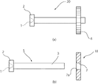
以下、図1ないし図4に基づき本発明の本発明の炭素含有量の異なる鋼材部品20およびその製造方法の一実施例を説明する。まず、本発明の炭素含有量の異なる鋼材部品20は、図1(a)および図1(b)に示すように、軸状に形成された第1部材の一例である軸部品5と、この軸部品5に配された第2部材の一例であるギア部品10とから構成される。前記軸部品5は、一端にビット(図示せず)に係合する駆動穴1を備えた頭部2と、この頭部2の最大径よりも小さな直径からなる軸部3と、からなり、この頭部2および軸部3が一体に成形されている。一方、前記ギア部品10は、その全周に複数のギア6が成形されており、本実施例においては平歯車である。また、このギア部品10は、その中心に前記取付穴の一例である貫通穴7が設けられるとともに、この貫通穴7の少なくとも一方の入口に斜面が形成されてなる。なお、本実施例において、前記斜面は、図1(a)および図2に示すR部7aあるいは図4(b)に示す面取り部7bであり、どちらが形成されてもよい。
Hereinafter, an embodiment of a
この鋼材部品20は、前記ビットの回転により前記ギア部品10が前記軸部品5と一体になって回転するように構成されており、前記軸部品5および前記ギア部品10は、拡散接合によって一体に接合されている。前記拡散接合は、上述したように熱膨張率の差を利用しているため、本実施例において、前記軸部品5は、0.45%程度の炭素含有量からなる材質に設定される一方、前記ギア部品10は、0.12%程度の炭素含有量からなる材質に設定される。
The
次に、本発明の炭素含有量の異なる鋼材部品20の製造方法について以下に説明する。前記鋼材部品20の製造方法は、図2に示したように、圧造工程、組立工程、熱処理工程の順で行われている。
Next, the manufacturing method of the
前記圧造工程は、冷間圧造装置によって前記軸部品5あるいは前記ギア部品10をそれぞれ成形する工程である。また、前記軸部品5は、ヘッダ加工および後述するバニッシュ加工を順に経由して成形される一方、前記ギア部品10は、後述するシェービング加工を経由して成形されるため、前記冷間圧造装置は、前記頭部2、前記駆動穴1、前記軸部3をそれぞれ成形するヘッダ装置(図示せず)と、前記軸部3を研磨加工並みの表面粗さに仕上げる前記バニッシュ加工を行う転造装置30と、前記ギア部品10の前記貫通穴7および斜面をそれぞれ研磨加工並みの表面粗さに仕上げるシェービング加工および前記ギア6の成形を同時に行うプレス装置40と、に分かれる。つまり、前記軸部品5は、前記ヘッダ装置、前記転造装置30を順に経由して圧造される。
The forging step is a step of forming the
前記転造装置30は、図3に示すように一対の平ダイス31,32を対向に配してなり、何れか一方の前記平ダイスが摺動することで、挟み込んだ軸部3を転がしながら転造して仕上げる装置である。このため、前記平ダイス31,32は、それぞれ前記軸部3と接する面が滑らかな平面で仕上げられている。このように、前記転造装置30により前記軸部4を仕上げる加工が前記バニッシュ加工であり、このバニッシュ加工は、前記軸部3の表面粗さ(Rmax)を約0.8s程度に仕上げることができる。したがって、バニッシュ加工は転造により行うため、一般的な軸の研磨加工に比べて大幅に加工時間を短縮できる特徴がある。
As shown in FIG. 3, the rolling
前記プレス装置40は、図4(a)および図4(b)に示すように下降および上昇可能な打ち抜き工具37と、素材11を受ける受け治具35とからなり、前記打ち抜き工具37が下降することで、前記素材11を打ち抜き、前記ギア部品10を成形する装置である。前記打ち抜き工具37は、前記素材11を打ち抜き可能に形成されており、前記ギア6を成形する内歯ギア38と、前記貫通穴7および前記斜面をそれぞれ成形する軸状の刃39と、を備えてなる。前記シェービング加工は、前記貫通穴7および前記斜面を前記刃39によって研磨加工並みの表面粗さ仕上げることができ、一般的な穴の研磨加工に比べて大幅に加工時間を短縮できる特徴がある。
As shown in FIGS. 4A and 4B, the
ところで、前記軸部品5は、前記ヘッダ装置により加工されるため、本実施例においては、その素材が、JIS G3507−2に規定される冷間圧造用炭素鋼線のSWCH45Kに設定されている。また、このSWCH45Kは、炭素含有量が0.45%程度に設定されている。一方、前記ギア部品10は、前記プレス装置40により加工されており、本実施例においては、その素材が、JIS G3507−2に規定される冷間圧造用炭素鋼線のSWCH12Aに設定されており、このSWCH12Aは、炭素含有量が0.12%程度に設定されている。なお、これら軸部品5およびギア部品10の材質は、それぞれ上述の材質に限定されるものではなく、前記拡散接合が可能であればよい。
By the way, since the
前記組立工程は、圧入装置(図示せず)により、前記軸部品5および前記ギア部品10を圧入する圧入作業と、この圧入作業後に行う前記拡散接合と、に分かれている。前記圧入作業は、前記軸部品5の先端が前記斜面に案内され、前記ギア部品10が軸部3の所定の位置まで押し込まれる作業である。また、前記斜面が形成されているため、前記圧入作業を容易にできるばかりでなく、滑らかな前記軸部3の外周および前記貫通穴7の周面が圧入作業により傷付かない。したがって、前記軸部3および前記貫通穴7の接合界面に存在する隙間を最小限にできる。また、前記軸部3および前記貫通穴7の直径寸法は、圧入代が0.03mm以上0.06mm以下の範囲になるようそれぞれ設定されている。なぜならば、前記圧入代が0.01mmおよび0.02mmに設定すると後述する拡散接合後に、ギア部品10にトルクを負荷すると低いトルクでギア部品10が軸部品5から滑って空転するためである。また、前記圧入代が0.06mmを越えると前記斜面を形成しても圧入時に前記軸部3の外周および前記貫通穴7の周面に傷が付き、拡散接合後の接合力が弱く、前述同様に低いトルクで空転が生じるためである。
The assembly process is divided into a press-fitting operation for press-fitting the
前記拡散接合は、前記圧入作業を終えた前記軸部品5および前記ギア部品10を熱処理炉によって真空雰囲気中で加熱するものである。この加熱により前述の熱膨張率の差が作用して前記接合界面の密着面積が増加するとともに、密着面を通して原子の拡散が起こりそれぞれの接合が進行する。本実施例であると、拡散接合は、炉内温度が860℃に設定されるとともに、この温度の保持時間が150分に設定されている。なお、前記炉内温度および前記保持時間は、前記軸部品5およびギア部品10の材質によって最適にそれぞれ設定すればよく、適宜変更されることはいうまでもない。
In the diffusion bonding, the
前記熱処理工程は、前記拡散接合と、この拡散接合の後に行う焼き入れ作業と、に分かれている。つまり、前記拡散接合は、図2に示すように前記組立工程および熱処理工程に重なるものである。前記焼き入れ作業は、ギア部品10の強度を向上させるために行っており、本実施例において、ギア部品10の材質を低炭素鋼であるSWCH12Aに設定されているため、浸炭焼き入れとなっている。なお、この焼き入れ作業は、ギア部品10の強度が向上できればよいため、ギア部品10の材質が変われば例えば調質焼き入れであってもよく、焼き入れの種類が前記浸炭焼き入れに限定されるものではない。
The heat treatment step is divided into the diffusion bonding and a quenching operation performed after the diffusion bonding. That is, the diffusion bonding overlaps the assembly process and the heat treatment process as shown in FIG. The quenching operation is performed in order to improve the strength of the
1 駆動穴
2 頭部
3 軸部
5 軸部品
6 ギア
7 貫通穴
7a R部
7b 面取り部
10 ギア部品
20 鋼材部品(本発明)
30 転造装置
31 平ダイス
32 平ダイス
40 プレス装置
100 鋼材部品(従来)
100’ 鋼材部品
101 駆動穴
102 頭部
103 軸部
103’ 軸部
104 ツバ部
104a 突起部
105 軸部品
105’ 軸部品
106 ギア
107 貫通穴
110 ギア部品
DESCRIPTION OF SYMBOLS 1
30
100 ′
Claims (4)
前記第1部材および前記第2部材をそれぞれ圧造により成形して、これら第1部材および第2部材を圧入した後、圧入により前記第1部材および第2部材が接する接合界面を拡散接合により一体成形された炭素含有量の異なる鋼材部品において、
前記第1部材の接合界面を転造により仕上げるバニッシュ加工、前記第2部材の接合界面を打ち抜きにより仕上げるシェービング加工、の少なくとも何れか一方の加工により形成してなることを特徴とする炭素含有量の異なる鋼材部品。 A first member formed of a shaft-shaped material having a high carbon content, and a second member made of a material having a low carbon content with a mounting hole to which the first member can be attached;
The first member and the second member are respectively molded by forging, and after the first member and the second member are press-fitted, a joint interface where the first member and the second member are in contact by press-fitting is integrally formed by diffusion bonding. In steel parts with different carbon content,
The carbon content is characterized by being formed by at least one of a burnishing process that finishes the joining interface of the first member by rolling and a shaving process that finishes the joining interface of the second member by punching. Different steel parts.
前記圧造の工程は、第1部材の接合界面を転造により仕上げるバニッシュ加工、前記第2部材の接合界面を打ち抜きにより仕上げるシェービング加工、の少なくとも何れか一方の加工を含んでいることを特徴とする炭素含有量の異なる鋼材部品の製造方法。 Increasing the carbon content of the first member formed into a shaft shape, and setting the carbon content of the second member having a mounting hole to which the first member can be attached low, the first member and the first member A method of manufacturing steel parts having different carbon contents, in which two members are each formed by forging, the first member and the second member are press-fitted, and then the bonding interface where the first member and the second member are in contact is diffusion-bonded by press-fitting In
The forging step includes at least one of a burnishing process that finishes the joining interface of the first member by rolling and a shaving process that finishes the joining interface of the second member by punching. Manufacturing method for steel parts with different carbon contents.
Priority Applications (1)
| Application Number | Priority Date | Filing Date | Title |
|---|---|---|---|
| JP2012240863A JP2014091125A (en) | 2012-10-31 | 2012-10-31 | Steel component different in carbon content and method of manufacturing the same |
Applications Claiming Priority (1)
| Application Number | Priority Date | Filing Date | Title |
|---|---|---|---|
| JP2012240863A JP2014091125A (en) | 2012-10-31 | 2012-10-31 | Steel component different in carbon content and method of manufacturing the same |
Publications (2)
| Publication Number | Publication Date |
|---|---|
| JP2014091125A true JP2014091125A (en) | 2014-05-19 |
| JP2014091125A5 JP2014091125A5 (en) | 2014-12-25 |
Family
ID=50935601
Family Applications (1)
| Application Number | Title | Priority Date | Filing Date |
|---|---|---|---|
| JP2012240863A Pending JP2014091125A (en) | 2012-10-31 | 2012-10-31 | Steel component different in carbon content and method of manufacturing the same |
Country Status (1)
| Country | Link |
|---|---|
| JP (1) | JP2014091125A (en) |
Cited By (4)
| Publication number | Priority date | Publication date | Assignee | Title |
|---|---|---|---|---|
| JP2018197601A (en) * | 2017-05-25 | 2018-12-13 | いすゞ自動車株式会社 | Fixing method and fixing construction |
| WO2020129863A1 (en) * | 2018-12-21 | 2020-06-25 | 日本発條株式会社 | Joining method and joint body |
| JP2023104571A (en) * | 2022-01-18 | 2023-07-28 | 株式会社三條機械製作所 | Method for manufacturing shaft member with flange part and shaft member with flange part |
| DE102022110829B3 (en) | 2022-05-03 | 2023-09-28 | Schaeffler Technologies AG & Co. KG | Composite toothed shaft of an electromechanical axle drive train |
-
2012
- 2012-10-31 JP JP2012240863A patent/JP2014091125A/en active Pending
Cited By (7)
| Publication number | Priority date | Publication date | Assignee | Title |
|---|---|---|---|---|
| JP2018197601A (en) * | 2017-05-25 | 2018-12-13 | いすゞ自動車株式会社 | Fixing method and fixing construction |
| WO2020129863A1 (en) * | 2018-12-21 | 2020-06-25 | 日本発條株式会社 | Joining method and joint body |
| CN113195146A (en) * | 2018-12-21 | 2021-07-30 | 日本发条株式会社 | Bonding method and bonded body |
| JPWO2020129863A1 (en) * | 2018-12-21 | 2021-11-25 | 日本発條株式会社 | Joining method and joining body |
| JP2023104571A (en) * | 2022-01-18 | 2023-07-28 | 株式会社三條機械製作所 | Method for manufacturing shaft member with flange part and shaft member with flange part |
| JP7333426B2 (en) | 2022-01-18 | 2023-08-24 | 株式会社三條機械製作所 | Manufacturing method for shaft member having flange and shaft member having flange |
| DE102022110829B3 (en) | 2022-05-03 | 2023-09-28 | Schaeffler Technologies AG & Co. KG | Composite toothed shaft of an electromechanical axle drive train |
Similar Documents
| Publication | Publication Date | Title |
|---|---|---|
| US9605715B2 (en) | Method of manufacturing outer joint member of constant velocity universal joint, and outer joint member | |
| JP5040108B2 (en) | Manufacturing method of bearing ring member constituting rolling bearing unit for supporting wheel | |
| US20220297179A1 (en) | Hollow drive shaft using upsetting method and manufacturing method therefor | |
| JP2014091125A (en) | Steel component different in carbon content and method of manufacturing the same | |
| EP2937587B1 (en) | Manufacturing method for outer joint member of constant velocity universal joint and outer joint member | |
| JP2014091125A5 (en) | ||
| US10514070B2 (en) | Method for manufacturing outer joint member for constant velocity universal joint, shaft member and outer joint member | |
| CN103635662B (en) | Camshaft and corresponding manufacture method | |
| KR101178558B1 (en) | Manufacturing method of compressor pulley | |
| EP3045748A1 (en) | Hollow drive shaft and method for manufacturing same | |
| EP3159566B1 (en) | Method of manufacturing an outer joint member of a constant-velocity universal joint and outer joint member | |
| US9346117B2 (en) | Method of manufacturing an integrated member | |
| US8034201B2 (en) | Induction hardening method and jig used in induction hardening process | |
| JP2012197070A (en) | Manufacturing method for wheel rolling bearing device, and wheel rolling bearing device | |
| EP3309420A1 (en) | Outer joint member of constant-velocity universal joint | |
| KR20140024080A (en) | Universal joint for vehicle and manufacturing method thereof | |
| JP7333426B2 (en) | Manufacturing method for shaft member having flange and shaft member having flange | |
| EP3159564A1 (en) | Manufacturing method for constant velocity universal joint outer joint member and outer joint member | |
| EP2684626A1 (en) | Manufacturing method for wheel roller bearing device | |
| JP2014226691A (en) | Manufacturing method of outside joint member for constant velocity universal joint, and intermediate forged product processed to outside joint member | |
| JP2010265930A (en) | Pin type retainer, roller bearing, and method for manufacturing the roller bearing | |
| EP3156676B1 (en) | Method of manufacturing outer joint member for constant-velocity universal joint and outer joint member | |
| JP2002213469A (en) | Method of manufacturing hub unit for supporting wheel and manufacturing die therefor | |
| JP6256585B2 (en) | Manufacturing method of rolling bearing device for wheel | |
| JP2002139118A (en) | Rolling element for traction drive and manufacturing method for the same |
Legal Events
| Date | Code | Title | Description |
|---|---|---|---|
| A521 | Written amendment |
Free format text: JAPANESE INTERMEDIATE CODE: A523 Effective date: 20140822 |
|
| A521 | Written amendment |
Free format text: JAPANESE INTERMEDIATE CODE: A523 Effective date: 20141010 |
|
| A521 | Written amendment |
Free format text: JAPANESE INTERMEDIATE CODE: A821 Effective date: 20141010 |