WO2020129846A1 - Thrust washer - Google Patents
Thrust washer Download PDFInfo
- Publication number
- WO2020129846A1 WO2020129846A1 PCT/JP2019/048950 JP2019048950W WO2020129846A1 WO 2020129846 A1 WO2020129846 A1 WO 2020129846A1 JP 2019048950 W JP2019048950 W JP 2019048950W WO 2020129846 A1 WO2020129846 A1 WO 2020129846A1
- Authority
- WO
- WIPO (PCT)
- Prior art keywords
- oil
- oil groove
- thrust washer
- groove
- ring
- Prior art date
Links
Images


Classifications
-
- F—MECHANICAL ENGINEERING; LIGHTING; HEATING; WEAPONS; BLASTING
- F16—ENGINEERING ELEMENTS AND UNITS; GENERAL MEASURES FOR PRODUCING AND MAINTAINING EFFECTIVE FUNCTIONING OF MACHINES OR INSTALLATIONS; THERMAL INSULATION IN GENERAL
- F16C—SHAFTS; FLEXIBLE SHAFTS; ELEMENTS OR CRANKSHAFT MECHANISMS; ROTARY BODIES OTHER THAN GEARING ELEMENTS; BEARINGS
- F16C33/00—Parts of bearings; Special methods for making bearings or parts thereof
- F16C33/02—Parts of sliding-contact bearings
- F16C33/04—Brasses; Bushes; Linings
- F16C33/06—Sliding surface mainly made of metal
- F16C33/10—Construction relative to lubrication
- F16C33/1025—Construction relative to lubrication with liquid, e.g. oil, as lubricant
- F16C33/1045—Details of supply of the liquid to the bearing
- F16C33/1055—Details of supply of the liquid to the bearing from radial inside, e.g. via a passage through the shaft and/or inner sleeve
-
- F—MECHANICAL ENGINEERING; LIGHTING; HEATING; WEAPONS; BLASTING
- F16—ENGINEERING ELEMENTS AND UNITS; GENERAL MEASURES FOR PRODUCING AND MAINTAINING EFFECTIVE FUNCTIONING OF MACHINES OR INSTALLATIONS; THERMAL INSULATION IN GENERAL
- F16C—SHAFTS; FLEXIBLE SHAFTS; ELEMENTS OR CRANKSHAFT MECHANISMS; ROTARY BODIES OTHER THAN GEARING ELEMENTS; BEARINGS
- F16C17/00—Sliding-contact bearings for exclusively rotary movement
- F16C17/04—Sliding-contact bearings for exclusively rotary movement for axial load only
- F16C17/08—Sliding-contact bearings for exclusively rotary movement for axial load only for supporting the end face of a shaft or other member, e.g. footstep bearings
-
- F—MECHANICAL ENGINEERING; LIGHTING; HEATING; WEAPONS; BLASTING
- F16—ENGINEERING ELEMENTS AND UNITS; GENERAL MEASURES FOR PRODUCING AND MAINTAINING EFFECTIVE FUNCTIONING OF MACHINES OR INSTALLATIONS; THERMAL INSULATION IN GENERAL
- F16C—SHAFTS; FLEXIBLE SHAFTS; ELEMENTS OR CRANKSHAFT MECHANISMS; ROTARY BODIES OTHER THAN GEARING ELEMENTS; BEARINGS
- F16C17/00—Sliding-contact bearings for exclusively rotary movement
- F16C17/04—Sliding-contact bearings for exclusively rotary movement for axial load only
- F16C17/045—Sliding-contact bearings for exclusively rotary movement for axial load only with grooves in the bearing surface to generate hydrodynamic pressure, e.g. spiral groove thrust bearings
-
- F—MECHANICAL ENGINEERING; LIGHTING; HEATING; WEAPONS; BLASTING
- F16—ENGINEERING ELEMENTS AND UNITS; GENERAL MEASURES FOR PRODUCING AND MAINTAINING EFFECTIVE FUNCTIONING OF MACHINES OR INSTALLATIONS; THERMAL INSULATION IN GENERAL
- F16C—SHAFTS; FLEXIBLE SHAFTS; ELEMENTS OR CRANKSHAFT MECHANISMS; ROTARY BODIES OTHER THAN GEARING ELEMENTS; BEARINGS
- F16C17/00—Sliding-contact bearings for exclusively rotary movement
- F16C17/04—Sliding-contact bearings for exclusively rotary movement for axial load only
- F16C17/047—Sliding-contact bearings for exclusively rotary movement for axial load only with fixed wedges to generate hydrodynamic pressure
-
- F—MECHANICAL ENGINEERING; LIGHTING; HEATING; WEAPONS; BLASTING
- F16—ENGINEERING ELEMENTS AND UNITS; GENERAL MEASURES FOR PRODUCING AND MAINTAINING EFFECTIVE FUNCTIONING OF MACHINES OR INSTALLATIONS; THERMAL INSULATION IN GENERAL
- F16C—SHAFTS; FLEXIBLE SHAFTS; ELEMENTS OR CRANKSHAFT MECHANISMS; ROTARY BODIES OTHER THAN GEARING ELEMENTS; BEARINGS
- F16C33/00—Parts of bearings; Special methods for making bearings or parts thereof
- F16C33/02—Parts of sliding-contact bearings
- F16C33/04—Brasses; Bushes; Linings
- F16C33/06—Sliding surface mainly made of metal
- F16C33/10—Construction relative to lubrication
- F16C33/1025—Construction relative to lubrication with liquid, e.g. oil, as lubricant
- F16C33/106—Details of distribution or circulation inside the bearings, e.g. details of the bearing surfaces to affect flow or pressure of the liquid
- F16C33/1065—Grooves on a bearing surface for distributing or collecting the liquid
-
- F—MECHANICAL ENGINEERING; LIGHTING; HEATING; WEAPONS; BLASTING
- F16—ENGINEERING ELEMENTS AND UNITS; GENERAL MEASURES FOR PRODUCING AND MAINTAINING EFFECTIVE FUNCTIONING OF MACHINES OR INSTALLATIONS; THERMAL INSULATION IN GENERAL
- F16C—SHAFTS; FLEXIBLE SHAFTS; ELEMENTS OR CRANKSHAFT MECHANISMS; ROTARY BODIES OTHER THAN GEARING ELEMENTS; BEARINGS
- F16C33/00—Parts of bearings; Special methods for making bearings or parts thereof
- F16C33/02—Parts of sliding-contact bearings
- F16C33/04—Brasses; Bushes; Linings
- F16C33/06—Sliding surface mainly made of metal
- F16C33/10—Construction relative to lubrication
- F16C33/1025—Construction relative to lubrication with liquid, e.g. oil, as lubricant
- F16C33/106—Details of distribution or circulation inside the bearings, e.g. details of the bearing surfaces to affect flow or pressure of the liquid
- F16C33/107—Grooves for generating pressure
-
- F—MECHANICAL ENGINEERING; LIGHTING; HEATING; WEAPONS; BLASTING
- F16—ENGINEERING ELEMENTS AND UNITS; GENERAL MEASURES FOR PRODUCING AND MAINTAINING EFFECTIVE FUNCTIONING OF MACHINES OR INSTALLATIONS; THERMAL INSULATION IN GENERAL
- F16C—SHAFTS; FLEXIBLE SHAFTS; ELEMENTS OR CRANKSHAFT MECHANISMS; ROTARY BODIES OTHER THAN GEARING ELEMENTS; BEARINGS
- F16C33/00—Parts of bearings; Special methods for making bearings or parts thereof
- F16C33/02—Parts of sliding-contact bearings
- F16C33/04—Brasses; Bushes; Linings
- F16C33/06—Sliding surface mainly made of metal
- F16C33/10—Construction relative to lubrication
- F16C33/1025—Construction relative to lubrication with liquid, e.g. oil, as lubricant
- F16C33/106—Details of distribution or circulation inside the bearings, e.g. details of the bearing surfaces to affect flow or pressure of the liquid
- F16C33/1075—Wedges, e.g. ramps or lobes, for generating pressure
-
- F—MECHANICAL ENGINEERING; LIGHTING; HEATING; WEAPONS; BLASTING
- F16—ENGINEERING ELEMENTS AND UNITS; GENERAL MEASURES FOR PRODUCING AND MAINTAINING EFFECTIVE FUNCTIONING OF MACHINES OR INSTALLATIONS; THERMAL INSULATION IN GENERAL
- F16C—SHAFTS; FLEXIBLE SHAFTS; ELEMENTS OR CRANKSHAFT MECHANISMS; ROTARY BODIES OTHER THAN GEARING ELEMENTS; BEARINGS
- F16C33/00—Parts of bearings; Special methods for making bearings or parts thereof
- F16C33/02—Parts of sliding-contact bearings
- F16C33/04—Brasses; Bushes; Linings
- F16C33/06—Sliding surface mainly made of metal
- F16C33/12—Structural composition; Use of special materials or surface treatments, e.g. for rust-proofing
- F16C33/122—Multilayer structures of sleeves, washers or liners
-
- F—MECHANICAL ENGINEERING; LIGHTING; HEATING; WEAPONS; BLASTING
- F16—ENGINEERING ELEMENTS AND UNITS; GENERAL MEASURES FOR PRODUCING AND MAINTAINING EFFECTIVE FUNCTIONING OF MACHINES OR INSTALLATIONS; THERMAL INSULATION IN GENERAL
- F16C—SHAFTS; FLEXIBLE SHAFTS; ELEMENTS OR CRANKSHAFT MECHANISMS; ROTARY BODIES OTHER THAN GEARING ELEMENTS; BEARINGS
- F16C33/00—Parts of bearings; Special methods for making bearings or parts thereof
- F16C33/02—Parts of sliding-contact bearings
- F16C33/04—Brasses; Bushes; Linings
- F16C33/20—Sliding surface consisting mainly of plastics
- F16C33/203—Multilayer structures, e.g. sleeves comprising a plastic lining
-
- F—MECHANICAL ENGINEERING; LIGHTING; HEATING; WEAPONS; BLASTING
- F16—ENGINEERING ELEMENTS AND UNITS; GENERAL MEASURES FOR PRODUCING AND MAINTAINING EFFECTIVE FUNCTIONING OF MACHINES OR INSTALLATIONS; THERMAL INSULATION IN GENERAL
- F16C—SHAFTS; FLEXIBLE SHAFTS; ELEMENTS OR CRANKSHAFT MECHANISMS; ROTARY BODIES OTHER THAN GEARING ELEMENTS; BEARINGS
- F16C2206/00—Materials with ceramics, cermets, hard carbon or similar non-metallic hard materials as main constituents
- F16C2206/02—Carbon based material
- F16C2206/04—Diamond like carbon [DLC]
-
- F—MECHANICAL ENGINEERING; LIGHTING; HEATING; WEAPONS; BLASTING
- F16—ENGINEERING ELEMENTS AND UNITS; GENERAL MEASURES FOR PRODUCING AND MAINTAINING EFFECTIVE FUNCTIONING OF MACHINES OR INSTALLATIONS; THERMAL INSULATION IN GENERAL
- F16C—SHAFTS; FLEXIBLE SHAFTS; ELEMENTS OR CRANKSHAFT MECHANISMS; ROTARY BODIES OTHER THAN GEARING ELEMENTS; BEARINGS
- F16C2208/00—Plastics; Synthetic resins, e.g. rubbers
- F16C2208/02—Plastics; Synthetic resins, e.g. rubbers comprising fillers, fibres
-
- F—MECHANICAL ENGINEERING; LIGHTING; HEATING; WEAPONS; BLASTING
- F16—ENGINEERING ELEMENTS AND UNITS; GENERAL MEASURES FOR PRODUCING AND MAINTAINING EFFECTIVE FUNCTIONING OF MACHINES OR INSTALLATIONS; THERMAL INSULATION IN GENERAL
- F16C—SHAFTS; FLEXIBLE SHAFTS; ELEMENTS OR CRANKSHAFT MECHANISMS; ROTARY BODIES OTHER THAN GEARING ELEMENTS; BEARINGS
- F16C2208/00—Plastics; Synthetic resins, e.g. rubbers
- F16C2208/20—Thermoplastic resins
-
- F—MECHANICAL ENGINEERING; LIGHTING; HEATING; WEAPONS; BLASTING
- F16—ENGINEERING ELEMENTS AND UNITS; GENERAL MEASURES FOR PRODUCING AND MAINTAINING EFFECTIVE FUNCTIONING OF MACHINES OR INSTALLATIONS; THERMAL INSULATION IN GENERAL
- F16C—SHAFTS; FLEXIBLE SHAFTS; ELEMENTS OR CRANKSHAFT MECHANISMS; ROTARY BODIES OTHER THAN GEARING ELEMENTS; BEARINGS
- F16C2223/00—Surface treatments; Hardening; Coating
- F16C2223/30—Coating surfaces
-
- F—MECHANICAL ENGINEERING; LIGHTING; HEATING; WEAPONS; BLASTING
- F16—ENGINEERING ELEMENTS AND UNITS; GENERAL MEASURES FOR PRODUCING AND MAINTAINING EFFECTIVE FUNCTIONING OF MACHINES OR INSTALLATIONS; THERMAL INSULATION IN GENERAL
- F16C—SHAFTS; FLEXIBLE SHAFTS; ELEMENTS OR CRANKSHAFT MECHANISMS; ROTARY BODIES OTHER THAN GEARING ELEMENTS; BEARINGS
- F16C2240/00—Specified values or numerical ranges of parameters; Relations between them
- F16C2240/30—Angles, e.g. inclinations
-
- F—MECHANICAL ENGINEERING; LIGHTING; HEATING; WEAPONS; BLASTING
- F16—ENGINEERING ELEMENTS AND UNITS; GENERAL MEASURES FOR PRODUCING AND MAINTAINING EFFECTIVE FUNCTIONING OF MACHINES OR INSTALLATIONS; THERMAL INSULATION IN GENERAL
- F16C—SHAFTS; FLEXIBLE SHAFTS; ELEMENTS OR CRANKSHAFT MECHANISMS; ROTARY BODIES OTHER THAN GEARING ELEMENTS; BEARINGS
- F16C2240/00—Specified values or numerical ranges of parameters; Relations between them
- F16C2240/40—Linear dimensions, e.g. length, radius, thickness, gap
-
- F—MECHANICAL ENGINEERING; LIGHTING; HEATING; WEAPONS; BLASTING
- F16—ENGINEERING ELEMENTS AND UNITS; GENERAL MEASURES FOR PRODUCING AND MAINTAINING EFFECTIVE FUNCTIONING OF MACHINES OR INSTALLATIONS; THERMAL INSULATION IN GENERAL
- F16C—SHAFTS; FLEXIBLE SHAFTS; ELEMENTS OR CRANKSHAFT MECHANISMS; ROTARY BODIES OTHER THAN GEARING ELEMENTS; BEARINGS
- F16C2240/00—Specified values or numerical ranges of parameters; Relations between them
- F16C2240/90—Surface areas
-
- F—MECHANICAL ENGINEERING; LIGHTING; HEATING; WEAPONS; BLASTING
- F16—ENGINEERING ELEMENTS AND UNITS; GENERAL MEASURES FOR PRODUCING AND MAINTAINING EFFECTIVE FUNCTIONING OF MACHINES OR INSTALLATIONS; THERMAL INSULATION IN GENERAL
- F16C—SHAFTS; FLEXIBLE SHAFTS; ELEMENTS OR CRANKSHAFT MECHANISMS; ROTARY BODIES OTHER THAN GEARING ELEMENTS; BEARINGS
- F16C2360/00—Engines or pumps
- F16C2360/42—Pumps with cylinders or pistons
-
- F—MECHANICAL ENGINEERING; LIGHTING; HEATING; WEAPONS; BLASTING
- F16—ENGINEERING ELEMENTS AND UNITS; GENERAL MEASURES FOR PRODUCING AND MAINTAINING EFFECTIVE FUNCTIONING OF MACHINES OR INSTALLATIONS; THERMAL INSULATION IN GENERAL
- F16C—SHAFTS; FLEXIBLE SHAFTS; ELEMENTS OR CRANKSHAFT MECHANISMS; ROTARY BODIES OTHER THAN GEARING ELEMENTS; BEARINGS
- F16C2360/00—Engines or pumps
- F16C2360/43—Screw compressors
-
- F—MECHANICAL ENGINEERING; LIGHTING; HEATING; WEAPONS; BLASTING
- F16—ENGINEERING ELEMENTS AND UNITS; GENERAL MEASURES FOR PRODUCING AND MAINTAINING EFFECTIVE FUNCTIONING OF MACHINES OR INSTALLATIONS; THERMAL INSULATION IN GENERAL
- F16C—SHAFTS; FLEXIBLE SHAFTS; ELEMENTS OR CRANKSHAFT MECHANISMS; ROTARY BODIES OTHER THAN GEARING ELEMENTS; BEARINGS
- F16C2361/00—Apparatus or articles in engineering in general
- F16C2361/43—Clutches, e.g. disengaging bearing
-
- F—MECHANICAL ENGINEERING; LIGHTING; HEATING; WEAPONS; BLASTING
- F16—ENGINEERING ELEMENTS AND UNITS; GENERAL MEASURES FOR PRODUCING AND MAINTAINING EFFECTIVE FUNCTIONING OF MACHINES OR INSTALLATIONS; THERMAL INSULATION IN GENERAL
- F16C—SHAFTS; FLEXIBLE SHAFTS; ELEMENTS OR CRANKSHAFT MECHANISMS; ROTARY BODIES OTHER THAN GEARING ELEMENTS; BEARINGS
- F16C2361/00—Apparatus or articles in engineering in general
- F16C2361/61—Toothed gear systems, e.g. support of pinion shafts
-
- F—MECHANICAL ENGINEERING; LIGHTING; HEATING; WEAPONS; BLASTING
- F16—ENGINEERING ELEMENTS AND UNITS; GENERAL MEASURES FOR PRODUCING AND MAINTAINING EFFECTIVE FUNCTIONING OF MACHINES OR INSTALLATIONS; THERMAL INSULATION IN GENERAL
- F16C—SHAFTS; FLEXIBLE SHAFTS; ELEMENTS OR CRANKSHAFT MECHANISMS; ROTARY BODIES OTHER THAN GEARING ELEMENTS; BEARINGS
- F16C33/00—Parts of bearings; Special methods for making bearings or parts thereof
- F16C33/02—Parts of sliding-contact bearings
- F16C33/04—Brasses; Bushes; Linings
- F16C33/20—Sliding surface consisting mainly of plastics
- F16C33/201—Composition of the plastic
Definitions
- the present invention relates to a thrust washer.
- thrust washers as shown in, for example, Patent Documents 1 to 4 may be attached.
- an oil groove is formed so as to extend from the insertion hole toward the outer peripheral side.
- the thrust washer disclosed in Patent Document 2 includes a first oil passage that connects the inner peripheral surface and the outer peripheral surface of the thrust washer, and a dead end second oil that opens on the inner peripheral surface but does not open on the outer peripheral surface. And a road is provided.
- the thrust washer disclosed in Patent Document 3 is provided with an arc-shaped oil supply groove and a V-shaped oil supply groove. Further, the thrust washer disclosed in Patent Document 4 has a first oil groove and a second oil groove extending from the inner peripheral edge to the outer peripheral edge, and a communication oil groove communicating the first oil groove and the second oil groove. A configuration is disclosed.
- the thrust washer has an opposing mating material
- the lubricating oil is present between the thrust washer and the mating material.
- the lubrication state of the thrust washer is assumed to be in the mixed lubrication region in the Stribeck diagram, and although part of the thrust washer is separated from the mating material by the oil film of lubricating oil, It is considered that the thrust washer is in direct contact with the mating material.
- the present invention has been made based on the above circumstances, and an object thereof is to provide a thrust washer capable of reducing a sliding load.
- a thrust washer made of a material containing a resin having a ring-shaped portion surrounding an insertion hole, wherein the thrust washer has a surface of the ring-shaped portion.
- a sliding surface that slides with other members is provided on the back surface, and at least one of the front surface and the back surface is provided with an oil groove that is recessed from the sliding surface and into which lubricating oil enters.
- the position of the thrust washer in the thickness direction is approximately the same as that of the sliding surface, and the sliding area ratio of the sliding surface to the projection surface in the plan view of the ring-shaped portion is 60 to 85%.
- a thrust washer is provided that is provided within the range.
- Another aspect of the present invention is, in the above-mentioned invention, at an intersecting position where the center line of the oil groove intersects with the center line in the radial direction of the ring-shaped portion, the radial direction passing through the intersecting position and along the radial direction.
- the inclination angle formed by the center line of the oil groove with respect to the line is preferably provided within the range of 30 degrees to 55 degrees.
- the oil groove is configured to guide the lubricating oil that has entered the oil groove to a sliding surface so that a dynamic pressure is applied between the sliding surface and another member. It is preferable that the dynamic pressure guide wall surface for causing the above is provided adjacently.
- the oil groove has a first oil groove inclined to one side with respect to a radial direction of the ring-shaped portion and a radial direction of the ring-shaped portion. It is preferable that a second oil groove that is inclined to the other side different from the one side is provided, and that the first oil groove and the second oil groove are connected by an opening.
- first oil groove and the second oil groove are respectively provided with bottom portions that are most recessed from the sliding surface, and the first oil groove and the second oil groove are provided.
- the groove is provided with a taper wall surface that is linearly inclined toward the sliding surface at a portion located outside that is not surrounded by the first oil groove and the second oil groove. It is preferable that the width is wider than that.
- Another aspect of the present invention is the above-described invention, wherein the first oil groove and the second oil groove have curved wall surfaces that are curved so that an inflection point exists from the bottom toward the sliding surface. It is preferably provided.
- another aspect of the present invention is, in the above-mentioned invention, in the oil groove, a non-communication oil groove separated from the outside of the ring-shaped portion by an oil stop wall, and the ring-shaped portion without the oil stop wall. It is preferable that a communication oil groove communicating with the outside of the is provided.
- the non-communication oil groove and the communication oil groove are provided alternately in the circumferential direction of the ring-shaped portion.
- another aspect of the present invention is, in the above-mentioned invention, in the communication oil groove, between an adjacent communication oil groove provided adjacent to the non-communication oil groove and a non-communication oil groove separated from each other. It is preferable that the intermediate communication oil groove existing in 1) is provided.
- another aspect of the present invention is, in the above-mentioned invention, in the oil groove, a non-communication oil groove separated from the outside of the ring-shaped portion by an oil stop wall, and the ring-shaped portion without the oil stop wall.
- a communication oil groove communicating with the outside of the first oil groove and the communication oil groove is formed in an opening portion adjacent to each other in the circumferential direction of the ring-shaped portion without interfering with the first oil groove and the second oil groove. It is preferable that it is arranged in a region between them.
- the non-communication oil groove is provided with a wide groove portion and a narrow groove portion having a groove width narrower than the wide groove portion, and the narrow groove portion is It is preferable that the wide groove portion is connected to the opening portion, is continuous with the narrow groove portion, and is provided on the oil stop wall side.
- an intermediate communication oil groove communicating with the outside is provided.
- an oil scooping surface that guides the lubricating oil to the opening is provided on the inner peripheral side of the ring-shaped portion, and the oil scooping surface is a ring. It is preferable that the opening is provided so as to be inclined with respect to the axial direction of the shaped portion, and the opening is formed by recessing the oil scooping surface.
- Another aspect of the present invention is the above-mentioned invention, wherein the height from the inner peripheral end of the oil scooping surface to the sliding surface is from the bottom of the oil groove, which is the most recessed to the sliding surface, to the sliding surface. It is preferable that the size is provided at least twice as large as the height.
- Another aspect of the present invention is the above-described invention, wherein the ring-shaped portion is provided with an oil introduction groove that is recessed from the inner diameter side of the ring-shaped portion toward the outer diameter side.
- the inclination angle formed by the groove bottom of the ring-shaped portion with respect to the axial direction is smaller than the inclination angle formed by the oil scooping surface with respect to the axial direction, and between the oil introduction groove and the oil scooping surface. It is preferable that a step is provided.
- At least a part of a boundary wall between the oil introduction groove and the oil scooping surface is provided to be inclined with respect to a radial direction of the ring-shaped portion. , Is preferred.
- FIG. 22 is a cross-sectional view showing a state in which the oil groove shown in FIG. 21 is cut along the width direction. It is a partial top view showing the composition of the resin thrust washer concerning the example of the 7th composition.
- FIG. 4 is a partial cross-sectional view showing a state in which the resin thrust washer is cut along the radial direction and an enlarged view of the vicinity of the oil scooping surface. It is a sectional view showing a schematic structure of a load measuring device. It is a figure which shows the experimental result regarding the sliding area ratio and torque (average torque) of the resin-made thrust washer which concerns on a 1st structural example. It is a figure which shows the experimental result regarding the sliding area ratio and torque (average torque) of the resin-made thrust washer which concerns on a 2nd structural example. It is a figure which shows the experimental result regarding the relationship between the sliding area ratio and torque (average torque) of the resin-made thrust washer which concerns on a 4th structural example. It is a top view showing the composition of the resin thrust washer concerning the modification of the 12th example of composition. It is a top view which shows the structure of the resin-made thrust washer which concerns on the modification of the 13th structural example.
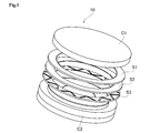
- the combined thrust washer 10 is incorporated in, for example, a transmission device of a vehicle or a compressor of an air conditioner device of a vehicle.
- the structure of this combined thrust washer 10 is shown in FIG.
- FIG. 1 is a perspective view showing the configuration of the combined thrust washer 10.
- the combined thrust washer 10 of the present embodiment includes three thrust washers S1, S2, S3.
- the combined thrust washer 10 including the three thrust washers S1, S2, S3 is located between the mating members C1, C2 and is in a state of receiving a load in the thrust direction.
- the environment in which the combined thrust washer 10 and the mating members C1 and C2 are provided is the environment in which the lubricating oil is supplied.
- the combined thrust washer 10 is obtained.
- the lubrication state of the environment in which is used is assumed to be in the mixed lubrication region in the Stribeck diagram. Therefore, it is presumed that an oil film is present between a part of the thrust washer and the mating member, and a part of the thrust washer is in direct contact with the mating member.
- the above thrust washers S1, S2, S3 include (1) resin-made thrust washers 20 made of resin (see FIGS. 2 and 3) and (2) metal-made thrust washers made of metal. It is configured to include at least one resin thrust washer 20. Specifically, in the combined thrust washer 10 shown in FIG. 1, the resin thrust washer 20 may be arranged on the mating member C1 side and the mating member C2 side and the metal thrust washer may be arranged at the center. The resin thrust washer 20 may be disposed only on the side and the rest may be a metal thrust washer, and the resin thrust washer 20 may be disposed only on the mating material C2 side and the rest may be a metal thrust washer.
- the metal thrust washers may be arranged only on the mating member C1 side and the remaining two may be resin thrust washers 20, and the metal thrust washers may be arranged only on the mating member C2 side and the remaining two are resin thrust washers.
- the washer 20 may be used, or the metal thrust washers may be arranged on both the mating member C1 side and the mating member C2 side, and the resin thrust washer 20 may be arranged at the center. Further, all of the above three thrust washers S1, S2, S3 may be resin thrust washers 20.
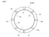
- FIG. 2 is a plan view showing the configuration of the resin-made thrust washer 20 that constitutes the combined thrust washer 10 shown in FIG.
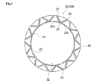
- FIG. 3 is a plan view showing the structure of the resin-made thrust washer 20 that constitutes the combined thrust washer 10 shown in FIG. 1.
- Two oil grooves 25 having different inclination angles are connected by an opening 27. It is a figure which shows a structure. In the configuration shown in FIG. 3, two oil grooves 25 having different inclination angles are connected at the opening 27, so that the entire oil groove 25 has a substantially V-shaped configuration.
- a resin-made thrust washer 20 configured such that one oil groove 25 is not connected to another oil groove 25 in a substantially V-shape is referred to as a resin-made thrust washer 20A.
- the resin-made thrust washer 20 having the oil groove 25 connected so as to draw a substantially V-shape as shown in FIG. 3 is referred to as a resin-made thrust washer 20B.
- the resin thrust washer 20 is simply referred to as the resin thrust washer 20.
- the resin-made thrust washers 20 are made of (1) a resin base material alone, (2) a resin base material mixed with a fibrous material, (3) a resin base material mixed with a filler, and (4) a resin. Either the base material mixed with the fibrous material and the filler is used.
- the resin base material, the fiber material, and the filler will be described below.
- the resin base material is tetrafluoroethylene resin (PTFE), polyamide resin (PA), polyamideimide resin (PAI), polyimide resin (PI), polybenzimidazole resin (PBI), aromatic polyetherketones (PAEK).
- PTFE tetrafluoroethylene resin
- PA polyamide resin
- PAI polyamideimide resin
- PI polyimide resin
- PBI polybenzimidazole resin
- PAEK aromatic polyetherketones
- Modified polyetherketone resin polyphenylene sulfide resin (PPS), liquid crystal polymer, phenol resin, polyethylene resin, polystyrene resin, acrylic resin, acrylonitrile butadiene/styrene resin, polyacetal resin, polycarbonate resin, polyether sulfone resin (PES), It is either a polyetherimide resin (PEI) or a mixture (including a polymer alloy and a copolymer) in which a plurality of them are selected and mixed.
- PPS polyphenylene sulfide resin
- liquid crystal polymer phenol resin
- PES polyethylene resin
- polystyrene resin acrylic resin
- acrylonitrile butadiene/styrene resin polyacetal resin
- polycarbonate resin polyether sulfone resin
- PES polyether sulfone resin
- PEI polyetherimide resin
- mixture including a polymer alloy and a copolymer
- the fibrous material is a reinforcing fiber having an average fiber length of, for example, about 0.0001 mm to 5 mm, and the fibrous material is made of inorganic fiber such as carbon fiber, glass fiber, potassium titanate fiber and the like. , Aramid fiber, fluorine fiber, etc. are used as a material, but not limited to these. Further, at least one fiber material may be selected from the above-mentioned fiber materials, and fiber materials of other materials may be selected and mixed.
- the weight ratio of the mixing ratio per product is preferably 1 to 40% by weight.
- the weight ratio of the mixing ratio per product is preferably 1 to 45% by weight.
- the weight ratio of the mixing ratio per product is preferably 5 to 55% by weight.
- the fibrous material is potassium titanate, the weight ratio of the mixing ratio per product is preferably 0.1 to 5% by weight.
- the filler is any one of tetrafluoroethylene resin (PTFE), manganese sulfide (MnS), molybdenum disulfide (MoS 2 ), graphite, calcium carbonate (CaCo 3 ), titanium oxide, and melamine cyanurate (MCA). , Or a mixture of a plurality of these selected.
- PTFE tetrafluoroethylene resin
- MnS manganese sulfide
- MoS 2 molybdenum disulfide
- MoCo 3 calcium carbonate
- titanium oxide titanium oxide
- MCA melamine cyanurate
- the surface treatment of the resin-made thrust washer 20 is a surface modification treatment using epoxysilane (manufactured by Shin-Etsu Silicone Co., Ltd.), a titanate-aluminate-based coupling agent.
- a coupling treatment using corona discharge or ion plasma discharge may be performed, and instead of the above surface modification treatment, DLC treatment or Mo coating. May be performed.
- the DLC treatment is preferable because it can reduce friction and improve wear resistance at the sliding portion.
- an oil scooping surface 24 is provided on the inner peripheral side of the ring-shaped portion 21 (the insertion hole 22 side).
- the oil scooping surface 24 is a portion that guides the lubricating oil introduced from the oil introducing groove 23 in the circumferential direction of the ring-shaped portion 21.
- the oil scooping surface 24 is formed by processing the inner peripheral side of the ring-shaped portion 21 into, for example, a tapered shape or a curved surface shape.
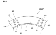
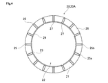
- FIG. 4 is a partial plan view showing the configuration of the resin thrust washer 20A according to the first configuration example.
- other members the mating members C1 and C2, the other resin-made thrust washers 20 and the metal-made thrust washers
- the front surface and the back surface of the ring-shaped portion 21 are referred to as the sliding surface 26.
- the opening 27 that opens toward the insertion hole 22 is provided on the inner diameter side of the oil groove 25. Therefore, the lubricating oil is supplied to the oil groove 25 from the insertion hole 22 side.
- the oil groove 25 is provided with a non-communication oil groove 25a and a communication oil groove 25b.
- the outer diameter side of the non-communication oil groove 25a does not communicate with the outer peripheral side of the resin thrust washer 20A (ring-shaped portion 21). That is, on the outer diameter side of the non-communication oil groove 25a, the oil stop wall 28 that suppresses the lubricating oil from flowing out to the outer peripheral side is arranged.
- the oil stop wall 28 is flush with the sliding surface 26, but the oil stop wall 28 may be provided so as to have a slight difference in height with respect to the sliding surface 26.
- the communication oil groove 25b the oil stop wall 28 does not exist on the outer diameter side of the ring-shaped portion 21, and the lubricating oil can flow from the inner diameter side (the insertion hole 22 side) to the outer diameter side.
- the width of the oil stop wall 28 is preferably within the range of 0.01 mm to 0.1 mm. It is difficult to make the width of the oil stop wall 28 smaller than 0.01 mm in terms of processing accuracy, and when the width of the oil stop wall 28 is made larger than 0.1 mm, the oil stop wall 28 has a smaller width. This is because the sliding load greatly affects the resin-made thrust washer 20.
- non-communication oil groove 25a and the communication oil groove 25b according to the first configuration example are provided along the radial direction.
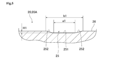
- the cross-sectional shape of the oil groove 25 (non-communication oil groove 25a and communication oil groove 25b) described above is configured as shown in FIG.
- a pair of tapered wall surfaces 252 is provided from the bottom 251 of the oil groove 25 toward the sliding surface 26 side.
- the tapered wall surface 252 is a portion that is linearly inclined with a predetermined inclination angle with respect to the sliding surface 26. Note that the tapered wall surface 252 may have a portion that inclines in a curved shape other than the linear shape.
- the area ratio of the oil groove to the ring-shaped portion 21 is 15 to 40%.
- the sliding area ratio of the sliding surface 26 obtained by subtracting the oil groove area ratio from the ring-shaped portion 21 is 60 to 85%. At this time, as described later, the sliding load is in the lowest state.
- the sliding area ratio refers to the ratio of the sliding surface 26 to the projection surface in the plan view of the resin thrust washer 20 (ring-shaped portion 21).
- the oil groove area ratio is the ratio of the projection surface in the plan view of the resin-made thrust washer 20 (ring-shaped portion 21) excluding the sliding surface 26 (of the portions not contacting the mating members C1 and C2). Ratio). Therefore, the oil groove area ratio is a portion lower than the sliding surface 26, that is, the oil scooping surface 24, the oil groove 25 (the non-communication oil groove 25a and the communication oil groove 25b), the dynamic pressure guide wall surface 254, and the surrounding portion 111. (See FIG. 23) and the like are included.
- the total number of the non-communication oil grooves 25a and the communication oil grooves 25b is eight. Moreover, since the non-communication oil grooves 25a and the communication oil grooves 25b are provided alternately in the circumferential direction, the same number of non-communication oil grooves 25a and communication oil grooves 25b are provided. However, the total number of the non-communication oil grooves 25a and the communication oil grooves 25b is not limited to eight. An example of such a configuration is shown in FIGS. 6 and 7.
- FIG. 6 is a plan view showing a configuration of a resin thrust washer 20A according to a modified example of the first configuration example.
- the total number of the non-communication oil grooves 25a and the communication oil grooves 25b is 16.
- FIG. 7 is a plan view showing a configuration of a resin thrust washer 20A according to a modified example of the first configuration example.
- the total number of the non-communication oil grooves 25a and the communication oil grooves 25b is 32.
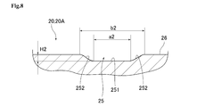
- FIG. 8 shows a cross-sectional shape of the oil groove 25 (non-communication oil groove 25a and communication oil groove 25b) shown in FIG.
- a pair of tapered wall surfaces 252 is provided from the bottom portion 251 toward the sliding surface 26 side.
- the tapered wall surface 252 is a portion that is linearly inclined with a predetermined inclination angle with respect to the sliding surface 26.
- the tapered wall surface 252 may have a portion that inclines in a curved shape other than the linear shape.
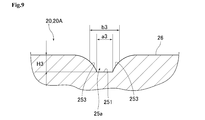
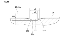
- FIG. 9 shows the cross-sectional shape of the non-communication oil groove 25a of the oil grooves 25 shown in FIG. Further, among the oil grooves 25 shown in FIG. 7, the cross-sectional shape of the communication oil groove 25b is shown in FIG.
- a convex curved surface portion 253 is provided instead of the tapered wall surface 252 as shown in FIGS.
- the convex curved surface portion 253 is a convex curved surface that connects the bottom portion 251 and the sliding surface 26, but unlike a substantially S-shaped curved surface (a curved wall surface described later), a cross-sectional shape that does not have an inflection point. Is.
- FIG. 9 shows the cross-sectional shape of the non-communication oil groove 25a of the oil grooves 25 shown in FIG.
- the cross-sectional shape of the communication oil groove 25b is shown in FIG.
- a convex curved surface portion 253 is provided instead of the tapered wall surface 252 as shown in FIGS.
- the convex curved surface portion 253 is provided, for example, in a shape equivalent to a chamfered round shape.
- the convex curved surface portion 253 may have, for example, a linear portion in part, or a concave curved surface portion in part, in addition to the convex curved surface portion.
- the convex curved surface portion 253 is provided as in the configuration shown in FIG.
- the oil groove 25 shown in FIGS. 8 and 9 may be configured as follows. That is, the dimensions a2, a3 and/or the dimensions b2, b3 of the oil groove 25 may be reduced toward the outer diameter side. At this time, the dimensions a2, a3 of the oil groove 25 may change linearly (proportionally) from the inner diameter side to the outer diameter side, but they may change not linearly (proportionally) but in a curve. Is also good. Further, the dimensions b2 and b3 of the oil groove 25 change in association with the dimension changes of the dimensions a2 and a3, but any mode of the dimension change may be used. Further, the dimensions b2, b3 of the oil groove 25 may be a constant dimension as a whole without interlocking with the dimension changes of the dimensions a2, a3. It may exist.
- the dimensions H2 and H3 corresponding to the depth of the oil groove 25 from the sliding surface 26 may be reduced toward the outer diameter side.
- the dimensions H2 and H3 of the oil groove 25 may be linearly (proportionally) decreased from the inner diameter side to the outer diameter side, but are changed linearly (proportionally) and curvedly. Is also good.
- both the dimensions a2, a3 and the dimensions H2, H3 may be reduced from the inner diameter side of the resin thrust washer 20A toward the outer diameter side.
- any of the dimensions a2, a3 and the dimensions H2, H3 may be reduced from the inner diameter side of the resin thrust washer 20A toward the outer diameter side.
- the oil groove area ratio (sliding area ratio) is approximately the same as that shown in FIG. 2, the configuration shown in FIG. 6, and the configuration shown in FIG. Are equal.
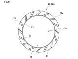
- FIG. 11 is a plan view showing the configuration of the resin thrust washer 20A according to the second configuration example.
- FIG. 12 is a partial plan view showing the configuration of the resin thrust washer 20A according to the second configuration example.
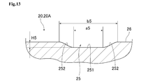
- FIG. 13 is a sectional view showing a state in which the oil groove 25 shown in FIGS. 11 and 12 is cut along the width direction.
- the oil groove 25 is composed of the non-communication oil groove 25a.
- the communication oil groove 25b is not provided.
- the oil groove 25 may employ a configuration in which the communication oil groove 25b is provided together with the non-communication oil groove 25a.
- the oil groove area ratio is 15 to 40%.
- the sliding area ratio of the sliding surface 26 is 60 to 85%, and the sliding load on the sliding surface 26 is the lowest, as will be described later.
- the inclination angle formed by the center line L2 with respect to the line similar to the radial line L3 at the same position as the above-described intersecting position P1 is the inclination angle. It may be described as ⁇ 1.
- the inclination angle ⁇ 1 is larger than 55 degrees, the non-communication oil groove 25a becomes long.
- the oil groove area ratio is a predetermined value within the range of 15 to 40%, the width dimension of the non-communication oil groove 25a becomes smaller as the length of the non-communication oil groove 25a becomes longer. .. Then, the width of the non-communication oil groove 25a becomes too narrow and the groove shape is collapsed, or it is necessary to reduce the number of non-communication oil grooves 25a due to interference with other non-communication oil grooves 25a. Therefore, the inclination angle ⁇ 1 is preferably 55 degrees or less. That is, the tilt angle ⁇ 1 is preferably 30 degrees or more and 55 degrees or less.
- a pair of tapered wall surfaces 252 is provided so as to extend from the bottom portion 251 of the oil groove 25 toward the sliding surface 26 side.
- the tapered wall surface 252 is a portion that is linearly inclined with a predetermined inclination angle with respect to the sliding surface 26, and in addition to the linear shape, there may be a portion that is curvedly curved. ..
- the resin-made thrust washer 20A according to the second configuration example may be configured as follows. That is, the oil groove 25 is not limited to a straight line shape, and may be provided in a curved line shape, or may be a mixture of straight lines and curved lines. Further, the dimension a5 and/or the dimension b5 (see FIG. 13) of the oil groove 25 may be reduced toward the outer diameter side. As an example of such a dimension, for example, the dimension a5 of the inner diameter side end of the oil groove 25 is 0.8 mm and the dimension of the outer diameter side end of the oil groove 25 is 0.03 mm. Is not limited.
- the dimension H5 (see FIG. 13) corresponding to the depth of the oil groove 25 from the sliding surface 26 may be reduced toward the outer diameter side.
- the dimension H5 of the oil groove 25 may be linearly (proportionally) decreased from the inner diameter side to the outer diameter side, but may be curved instead of being linear (proportional). ..
- both the dimension a5 and the dimension H5 may be reduced from the inner diameter side of the resin thrust washer 20A toward the outer diameter side.
- either the dimension a5 or the dimension H5 may become smaller from the inner diameter side of the resin thrust washer 20A toward the outer diameter side.
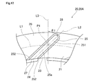
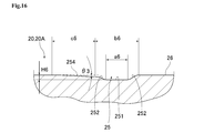
- FIG. 14 is a plan view showing the configuration of the resin thrust washer 20A according to the third configuration example.
- FIG. 15 is a partial plan view showing the configuration of the resin-made thrust washer 20A according to the second configuration example.
- FIG. 16 is a sectional view showing a state in which the oil groove 25 shown in FIGS. 14 and 15 is cut along the width direction.
- the oil groove 25 is the same as the oil groove 25 of the resin-made thrust washer 20A according to the second configuration example. 25a, and the communication oil groove 25b is not provided.
- the oil groove 25 may employ a configuration in which the communication oil groove 25b is provided together with the non-communication oil groove 25a.
- the oil groove 25 has a bottom portion 251 and a tapered wall surface 252.
- a dynamic pressure guide wall surface 254 is provided so as to be adjacent to the oil groove 25.
- the dynamic pressure guide wall surface 254 is a portion for facilitating the lubricating oil entering the non-communication oil groove 25a to be guided by the sliding surface 26. Therefore, the inclination angle ⁇ 3 (see FIG. 16) of the dynamic pressure guide wall surface 254 with respect to the sliding surface 26 is set to be significantly smaller than the inclination angle of the tapered wall surface 252 with respect to the sliding surface 26.
- the oil groove 25 provided in the resin-made thrust washer 20B is a non-communication oil groove 25a except for the communication oil groove 113 provided in the resin-made thrust washer 20 (see FIG. 27) according to the ninth configuration example described later. ..
- the resin thrust washer 20B may be provided with the communication oil groove 25b in configurations other than the ninth configuration example.
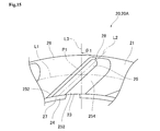
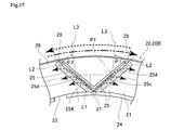
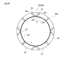
- FIG. 17 is a partial plan view showing the configuration of the resin thrust washer 20B according to the fourth configuration example.
- the resin-made thrust washer 20B is similar to the resin-made thrust washer 20A described above in that the ring-shaped portion 21, the insertion hole 22, the oil introduction groove 23, the sliding surface 26, and the opening 27. And an oil stop wall 28.
- the form of the oil groove 25 is different.
- two oil grooves 25 having different inclination angles are connected on the opening 27 side, and these two oil grooves 25 are arranged so as to draw a V shape.
- first oil groove 25c one of the oil grooves 25 that draws a substantially V shape
- second oil groove 25d one of the oil grooves 25 that draws a substantially V shape
- first oil groove 25c is provided so as to move clockwise from the inner diameter side toward the outer diameter side
- second oil groove 25d is provided so as to advance counterclockwise from the inner diameter side toward the outer diameter side.
- first oil groove 25c and the second oil groove 25d may be completely connected on the opening 27 side, but they may be slightly separated.
- the inclination angle ⁇ 1 of the first oil groove 25c and the second oil groove 25d is also within the range of 30 degrees to 55 degrees.
- the groove width of the oil groove 25 is preferably in the range of 1.8 mm to 2.8 mm.
- the groove depth of the oil groove 25 is preferably in the range of 0.5 mm to 1.0 mm.
- the inclination angle ⁇ 1 on the first oil groove 25c side and the inclination angle ⁇ 1 on the second oil groove 25d side may have different values.
- the cross-sectional shape of the oil groove 25 according to the fourth configuration example shown in FIGS. 3 and 17 is formed as shown in FIG.
- a pair of substantially S-shaped curved wall surfaces 255 are provided from the bottom 251 of the oil groove 25 toward the sliding surface 26 side. Therefore, the lubricating oil that has entered the oil groove 25 can be satisfactorily supplied to the sliding surface 26 on any of the pair of curved wall surfaces 255.
- a curved wall surface 255 on the other side is provided with a guide wall surface 254 for dynamic pressure so as to be continuous.
- the dynamic pressure guide wall surface 254 is a portion that is linearly inclined with a predetermined inclination angle with respect to the sliding surface 26.
- the dynamic pressure guide wall surface 254 may have a portion that inclines in a curved shape other than the linear shape.
- a total of 12 sets of the first oil groove 25c and the second oil groove 25d that draw a V shape are provided.
- the first oil groove 25c and the second oil groove 25d that draw a V shape are formed.
- a total of 6 sets are provided.
- any number of sets of the first oil groove 25c and the second oil groove 25d that draw a V shape may be provided.
- the two-dot chain line shows the case where the rotation direction of the resin thrust washer 20B is clockwise, and also shows the flow of the lubricating oil at that time.
- the resin thrust washer 20B rotates clockwise with respect to the lubricating oil existing on the side of the insertion hole 22
- the lubricating oil flowing into the oil groove 25 from the opening 27 is subjected to the centrifugal force to generate the first oil. It is supplied to the sliding surface 26 mainly from the second oil groove 25d instead of the groove 25c.
- the broken line shows the case where the rotation direction of the resin thrust washer 20 is counterclockwise, and also shows the flow of the lubricating oil at that time.
- the resin-made thrust washer 20 rotates counterclockwise, the lubricating oil is mainly supplied to the sliding surface 26 from the first oil groove 25c, not from the second oil groove 25d, by the centrifugal force acting on the lubricating oil.
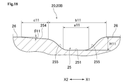
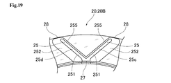
- FIG. 19 is a partial plan view showing the configuration of the resin thrust washer 20B according to the fifth configuration example.
- 20 is a cross-sectional view showing a state in which the oil groove 25 shown in FIG. 19 is cut along the width direction.
- the oil groove 25 of the resin-made thrust washer 20B according to the fifth configuration example is different from the oil groove 25 of the resin-made thrust washer 20B according to the fourth configuration example in the cross-sectional shape along the width direction, but the fifth configuration In the resin-made thrust washer 20B according to the example, the configuration other than the cross-sectional shape of the oil groove 25 is common to the resin-made thrust washer 20B according to the fourth configuration example.
- the taper wall surface 252 approaches the one side (X1 side in FIG. 20) from the bottom 251 of the oil groove 25. That is, the tapered wall surface 252 is continuous with one side of the bottom portion 251.
- the tapered wall surface 252 in the width direction (dimension c12) is set to be approximately four times the dimension a12 that is the length of the bottom portion 251 in the width direction.
- the tapered wall surface 252 is located on the inner diameter side of the curved wall surface 255 in the width direction of the oil groove 25. Is provided. As a result, when the resin thrust washer 20B is rotated, the lubricating oil is supplied to the sliding surface 26 at a portion not surrounded by the two oil grooves 25.
- the tapered wall surface 252 may be provided so as to be located on the outer diameter side of the curved wall surface 255 in the width direction of the oil groove 25.
- a total of six sets of the first oil groove 25c and the second oil groove 25d that draw a V shape are provided at equal intervals in the circumferential direction of the ring-shaped portion 21.
- any number of sets of the first oil groove 25c and the second oil groove 25d that draw a V shape may be provided.
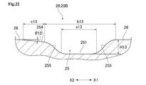
- FIG. 21 is a partial plan view showing the configuration of the resin thrust washer 20B according to the sixth configuration example.
- 22 is a cross-sectional view showing a state in which the oil groove 25 shown in FIG. 21 is cut along the width direction.
- the oil groove 25 according to the sixth configuration example has a different planar shape from the oil groove 25 according to the fourth configuration example, in the resin-made thrust washer 20B according to the sixth configuration example, the cross-sectional shape of the oil groove 25. Is common with the resin-made thrust washer 20B according to the fourth configuration example.
- a bottom portion 251 and a substantially S-shaped curve are formed from the bottom portion 251 toward the sliding surface 26 side.
- a pair of wall surfaces 255 are provided.
- the curved wall surface 255 on the other side is provided so as to be continuous with the dynamic pressure guide wall surface 254 that is linearly inclined.
- the oil groove 25 is provided with a branched oil groove 110 in addition to the first oil groove 25c and the second oil groove 25d which are connected so as to draw a V shape.
- the branched oil groove 110 is an oil groove connected so as to be branched from each of the first oil groove 25c and the second oil groove 25d.
- the branched oil groove 110 is connected to the first oil groove 25c and the second oil groove 25d, respectively, so that a lowercase letter "y" is drawn or vice versa.
- the outer diameter side of the branch oil groove 110 is not in communication with the outer peripheral side of the resin-made thrust washer 20B (ring-shaped portion 21), and an oil stopper is provided on the outer diameter side of the branch oil groove 110 like the oil groove 25.
- the wall 110a is arranged.
- the width of the branched oil groove 110 connected to the first oil groove 25c and the width of the branched oil groove 110 connected to the second oil groove 25d are equal.
- the widths of the two branched oil grooves 110 may be different from each other.
- the branched oil groove 110 connected to the first oil groove 25c may be wider than the width of the branched oil groove 110 connected to the second oil groove 25d, and vice versa. It may be.
- an oil stop wall 110 a that suppresses the lubricating oil from flowing out of the branch oil groove 110 from the outer peripheral side is provided.
- the width of the oil stop wall 110a can be set in the same manner as the width of the oil stop wall 28 described above.
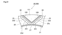
- FIG. 23 is a partial plan view showing the configuration of the resin thrust washer 20B according to the seventh configuration example.
- FIG. 24 is a cross-sectional view showing a state in which the oil groove 25 shown in FIG. 23 is cut along the width direction. Note that the oil groove 25 according to the seventh configuration example has a different planar shape from the oil groove 25 according to the fourth configuration example, but in the resin-made thrust washer 20B according to the seventh configuration example, the cross-sectional shape of the oil groove 25. The configuration excluding the vicinity is common to the resin thrust washer 20B according to the fourth configuration example.
- the tapered wall surface 252 is continuous with one side of the bottom portion 251.
- the inclined wall portion 109a is continuous with the other side of the bottom portion 251.
- the dimension of the tapered wall surface 252 in the width direction is set to be approximately twice the dimension a14 which is the length of the bottom portion 251 in the width direction. Has been done.
- the oil bank 109 is provided such that the height H141 from the bottom 251 is substantially the same as the height H142 of the sliding surface 26 from the bottom 251.
- the oil bank portion 109 is provided with a pair of inclined wall portions 109a and 109b with the top portion 109c interposed therebetween.
- the inclined wall portion 109a is an inclined wall located on the other side (X2 side) of the oil groove 25, and is inclined linearly.
- the inclined wall portion 109b is an inclined wall located on the opposite side of the inclined wall portion 109a with the top portion 109c interposed therebetween, and is inclined linearly like the inclined wall portion 109a. As shown in FIG.
- the inclined wall portion 109a is arranged on one side (X1 side) of the top portion 109c, and the inclined wall portion 109b is arranged on the other side (X2 side) of the top portion 109c.
- the inclined wall portions 109a and 109b are not limited to the linear shape, and may be provided in the curved shape.
- the bottom 251 side of the inclined wall portion 109a and the surrounding portion 111 (described later) side of the inclined wall portion 109b are provided in a straight line.
- the tops 109c side of the inclined wall portions 109a and 109b are provided in a curved shape.
- the top portion 109c is provided so as to be flat, the width of the top portion 109c is extremely narrow as compared with the width of the bottom portion 251 and the tapered wall surface 252. In this way, since the width of the top portion 109c is extremely narrow, even when the top portion 109c comes into contact with other members (other resin thrust washers 20, metal thrust washers, mating members C1, C2, etc.), It is provided so as to be in line contact. This point will be described in detail. As shown in FIGS. 23 and 24, these two oil grooves 25 (two oil stop walls 28) are provided between the first oil groove 25c and the second oil groove 25d. A surrounding portion 111 is provided. As shown in FIG.
- the height of the surrounding portion 111 is lower than that of the top portion 109c. Therefore, when the resin-made thrust washer 20 rotates, even if the top portion 109c comes into contact with other members, the surrounding portion 111 does not come into contact with other members.
- the lubricating oil that has passed over the top portion 109c covers the surrounding portion 111. Even if the lubricating oil covers the surrounding portion 111, the surrounding portion 111 does not come into contact with other members.
- the surrounding portion 111 having a low height may not come into contact with other members, while the top portion 109c may come into contact with other members.
- the sliding load can be reduced as compared with the configuration in which 111 does not exist.
- the height of the surrounding portion 111 may be the same as that of the bottom portion 251, or may be slightly higher or lower than that of the bottom portion 251.
- the top portion 109c may come into contact with other members, but of course, there is a case where the top portion 109c does not come into contact with other members due to the presence of lubricating oil. ..
- FIG. 25 is a partial plan view showing the configuration of the resin thrust washer 20B according to the eighth configuration example.
- FIG. 26 is a sectional view showing a state in which the oil groove 25 shown in FIG. 25 is cut along the width direction.
- the oil groove 25 according to the eighth configuration example has a planar shape different from that of the oil groove 25 according to the fourth configuration example
- the oil groove 25 is Like the four configuration examples, it has a bottom portion 251.
- the difference between the resin-made thrust washers 20B according to the eighth configuration example and the resin-made thrust washers 20B according to the fourth to seventh configuration examples will be described.
- the resin-made thrust washer 20B according to the eighth configuration example is provided with a convex curved surface portion 256 similar to the curved wall surface 255 having a substantially S shape.
- the convex curved surface portion 256 is a convex curved surface that connects the bottom portion 251 and the sliding surface 26, but unlike the substantially S-shaped curved wall surface 255, has a cross-sectional shape with no inflection point.
- the convex curved surface portion 256 is provided in a shape equivalent to, for example, a chamfered round shape.
- the convex curved surface portion 256 may have, for example, a linear portion in part, or a concave curved surface portion in part, in addition to the convex curved surface portion. Further, instead of the convex curved surface portion 256, a linear inclined surface equivalent to the tapered wall surface 252 may be provided.
- the oil groove 25 has a wide groove portion 257 and a narrow groove portion 258.
- the wide groove portion 257 and the narrow groove portion 258 are provided so as to be continuous on the same straight line.
- the wide groove portion 257 is provided so as to be wider than the narrow groove portion 258.
- the narrow groove portion 258 is connected to the opening portion 27, while the oil stop wall 28 exists on the inner side of the wide groove portion 257.
- the width of the wide groove portion 257 is set to be approximately twice to 2.5 times the width of the narrow groove portion 258.
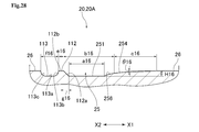
- FIG. 27 is a partial plan view showing the configuration of the resin thrust washer 20B according to the ninth configuration example.
- 28 is a sectional view showing a state in which the oil groove 25 shown in FIG. 27 is cut along the width direction.
- the oil groove 25 is different from the resin thrust washers 20B according to the fourth to eighth configuration examples in that the two oil grooves 25 are V-shaped.
- the oil groove 25 is arranged so as to extend in a direction inclined with respect to the radial direction.
- the two oil grooves 25 may be arranged so as to draw a V shape.
- the oil groove 25 according to the ninth configuration example includes a bottom portion 251 and a dynamic pressure guide wall surface 254. Further, the oil groove 25 according to the ninth configuration example includes a convex curved surface portion 256, similarly to the oil groove 25 according to the eighth configuration example.
- the resin thrust washer 20B according to the ninth configuration example is provided with the sliding projection 112 similar to the oil bank portion 109 when going from the bottom portion 251 to the other side (X2 side in FIGS. 27 and 28). There is.
- the sliding projection 112 is a portion for contacting the mating member C1 or C2 and smoothing the roughness on the surface of the mating member C1 or C2.
- the sliding projection 112 has the same height as the sliding surface 26, or is provided so as to slightly project from the sliding surface 26.
- a linear inclined surface equivalent to the tapered wall surface 252 may be provided.
- the sliding projection 112 may be provided slightly lower than the sliding surface 26.
- the top surface portion 112b is provided to be flat, like the top portion 109c. Further, a concave curved surface portion 113b described later is continuous with the top surface portion 112b.
- a communication oil groove 113 (corresponding to an adjacent communication oil groove) is provided from the sliding projection 112 toward the other side (X2 side in FIGS. 27 and 28). It is provided.
- the oil stop wall 28 does not exist on the outer diameter side of the ring-shaped portion 21, and the lubricating oil can flow freely from the insertion hole 22 to the outer diameter side.
- the communication oil groove 113 is provided so as to be recessed from the sliding surface 26 together with the oil groove 25. Further, in the configuration shown in FIGS. 27 and 28, the communication oil groove 113 is provided in a linear shape that is parallel to the oil groove 25.
- the communication oil groove 113 does not have to be parallel to the oil groove 25, and may be provided, for example, along the radial direction of the resin thrust washer 20A. Further, the communication oil groove 113 may be provided in a curved shape instead of a straight shape.
- the bottom 113a of the communication oil groove 113 is provided at the same height as the bottom 251. However, the height of the bottom 113a may be slightly different from the height of the bottom 251. .. Further, as shown in FIG. 28, the bottom portion 113a is continuously provided on the pair of concave curved surface portions 113b and 113c. Of these, a concave curved surface portion 113b is provided on one side (X1 side in FIG. 28) of the bottom portion 113a, and a concave curved surface portion 113c is provided on the other side (X2 side in FIG. 28) of the bottom portion 113a. ing.
- These concave curved surface portions 113b and 113c are concave curved surfaces that connect the bottom portion 113a and the sliding surface 26, and have a cross-sectional shape that does not have an inflection point, unlike the substantially S-shaped curved wall surface 255.
- the concave curved surface portions 113b and 113c are provided in the same shape as, for example, a chamfered round shape.
- the concave curved surface portions 113b and 113c may have, for example, a linear portion other than the curved portion.
- the bottom 113a may or may not have a curved portion.
- the resin thrust washer 20B according to the tenth configuration example is provided with the same oil groove 25 as the resin thrust washer 20B according to the fifth configuration example described above, and the similar oil groove 25 has a bottom portion 251. There is a curved wall surface 255 and a tapered wall surface 252 that are substantially S-shaped. Therefore, its illustration is omitted. However, in the tenth configuration example, a total of eight sets of the first oil groove 25c and the second oil groove 25d that draw a V shape are provided at equal intervals in the circumferential direction of the ring-shaped portion 21. This point is different from the fifth configuration example in which a total of six sets of the first oil groove 25c and the second oil groove 25d are provided in the ring-shaped portion 21.
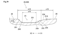
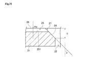
- FIG. 29 is a partial plan view showing the configuration of the resin thrust washer 20B according to the eleventh configuration example.
- FIG. 30 is a sectional view showing a state in which the oil groove 25 shown in FIG. 29 is cut along the width direction.
- the first oil groove 25c and the second oil groove 25d are provided with short lengths. Therefore, there is a sufficient distance between the inner side of the first oil groove 25c and the second oil groove 25d (the side away from the opening 27) and the outer peripheral edge of the resin thrust washer 20B.
- the resin-made thrust washer 20B according to the eleventh configuration example is provided with an oil sump groove 114 in addition to the oil groove 25.
- the oil sump groove 114 is a concave portion in which the opening 27 does not exist on the inner diameter side.
- two oil sump grooves 114 are provided. These two oil sump grooves 114 are connected on the inner diameter side so as to draw a V shape. However, the oil sump groove 114 does not have to be arranged so as to draw a V shape.
- one of the V-shaped oil sump grooves 114 will be referred to as a first oil sump groove 114a and the other will be referred to as a second oil sump groove 114b.
- the first oil sump groove 114a is provided so as to proceed clockwise from the inner diameter side toward the outer diameter side.
- the second oil sump groove 114b is provided so as to advance counterclockwise from the inner diameter side toward the outer diameter side.
- a substantially S-shaped curved wall surface 255 is formed.
- the substantially S-shaped curved wall surface 255 is continuous to one side of the bottom portion 251.
- a concave curved surface portion 259 that is a concave curved surface is continuously provided on the bottom portion 251
- a convex curved surface portion 256 that is a convex curved surface is continuous with the concave curved surface portion 259. It is provided.
- a dynamic pressure guide wall surface 254 is provided between the convex curved surface portion 256 and the sliding surface 26 so as to be continuous with them.
- a linear inclined surface equivalent to the tapered wall surface 252 may be provided.
- the concave curved surface portion 260 is provided continuously to the bottom portion 251. Further, the concave curved surface portion 260 is continuously provided with an inclined wall portion 261 that is linearly inclined. It should be noted that the sliding surface 26 is approached from the inclined wall portion 261 toward the other side (X2 side in FIG. 30). Moreover, the inclined wall portion 261 may be provided in a curved shape. Further, the inclined wall portion 261 may have a curved portion.
- a concave curved surface portion (not shown) and a convex curved surface similar to the concave curved surface portion 259 are formed.
- the sliding surface 26 is approached via a convex curved surface portion (not shown) similar to the portion 256 and a dynamic pressure guide wall surface 116 (see FIG. 29) similar to the dynamic pressure guide wall surface 254.
- the sliding surface 26 passes through a concave curved surface portion (not shown) similar to the concave curved surface portion 260 and an inclined wall portion (not shown) similar to the inclined wall portion 261.
- a linear inclined surface equivalent to the tapered wall surface 252 may be provided.
- the height from the bottom portion 251 to the sliding surface 26 (groove depth of the oil groove 25) H1 to H6, H11 to H13, H15, H16, H18, H141, H142 and the dimension of the oil scooping surface 24
- the relationship is as shown in FIG. That is, the height T from the inner peripheral end of the oil scooping surface 24 to the sliding surface 26 is larger than the height from the bottom 251 to the sliding surface 26 (hereinafter referred to as height Hx). Is provided.
- the thrust washer 10 rotates, the lubricating oil moves in the circumferential direction along the oil scooping surface 24 and flows into the oil groove 25 from each opening 27. Therefore, if the height T is not sufficiently larger than the height Hx, the amount of lubricating oil flowing into the oil groove 25 from the opening 27 may be small. For this reason, it is preferable that the height T is twice or more the height Hx.
- the inclination angle ⁇ of the oil scooping surface 24 with respect to the axial direction of the thrust washer 10 is preferably within the range of 30 to 60 degrees.
- the inclination angle ⁇ is smaller than 30 degrees, the dimension of the oil scooping surface 24 in the radial direction becomes small and the supply amount of the lubricating oil becomes small.
- the tilt angle ⁇ is preferably within the above range.
- the central 45 degrees in the range is given as a representative example, but the inclination angle ⁇ is appropriately selected from the range of 30 to 60 degrees. Can be selected.
- the inclination angle ⁇ may be outside the range of 30 to 60 degrees.
- the inclination angle ⁇ (not shown) formed by the groove bottom of the oil introduction groove 23 with respect to the axial direction is set smaller than the inclination angle ⁇ of the oil scooping surface 24 as described above.
- the inclination angle ⁇ is set to include 0 degree (it may be 0 degree) and smaller than the inclination angle ⁇ .
- a relatively large step is provided on the boundary wall between the oil introduction groove 23 and the oil scooping surface 24 (see FIG. 12, etc.). Therefore, when the lubricating oil enters the oil introduction groove 23, the lubricating oil can be satisfactorily supplied to the oil scooping surface 24 side.
- the inclination angle ⁇ is 0 degree
- the groove bottom portion of the oil introduction groove 23 is parallel to the axial direction.
- At least a part of the boundary wall between the oil introducing groove 23 and the oil scooping surface 24 is slightly inclined with respect to the radial direction of the thrust washer 10 (ring-shaped portion 21).
- the boundary wall is slightly inclined, for example, there is a configuration in which the root portion of the oil introducing groove 23 located on the outer side in the radial direction of the oil introducing groove 23 is formed into an R shape.
- a boundary wall may be provided so that the dimension in the circumferential direction becomes smaller than the inner side of the oil introduction groove 23 toward the outer side in the radial direction.
- the resin-made thrust washer 20A that has been tested has an outer diameter of 67 mm, an inner diameter of 49 mm, and a thickness of 1 mm.
- the oil groove 25 is provided on one side thereof, and in the resin-made thrust washer 20A according to the third configuration example, both surfaces thereof are provided. An oil groove 25 is provided.
- the resin-made thrust washer 20A is manufactured by using a product name 150FC30 (manufactured by Victorex Co., Ltd.) made of polyetherketone resin (PEK). Further, the resin-made thrust washer 20 is not surface-treated.
- the mating members C1 and C2 arranged to face the resin thrust washer 20A are made of high-strength steel S45C (JIS standard), the diameter thereof is 67 mm, and the surface roughness thereof is Rz 0.5 ⁇ m. .. Further, in this experiment, both sides of the resin-made thrust washer 20A were slid, but the mating materials C1 and C2 that were slid on both sides had a Vickers hardness (HV) of 180. Further, ATF was used as the oil type of the lubricating oil, and the oil temperature during the experiment was 120 degrees. In addition, during the experiment, the load was 1135 N, the rotation speed was 6800 rpm, and the oil flow rate was 100 cc/min.
- the load measuring device 300 includes a cylindrical oil pan 301, and the above-described lubricating oil is supplied to an inner cylinder portion 301a of the oil pan 301.
- the oil pan 301 is also provided with an oil outlet 301b.
- the oil discharge port 301b is an opening for discharging the lubricating oil existing in the inner cylinder portion 301a to the outside, and has a mechanism for forced discharge by a pump.
- the load measuring device 300 also includes a fixed shaft 302 and a rotating shaft 303.
- the fixed shaft 302 is a shaft that does not rotate relative to the oil pan 301. However, a load in the pressing direction is applied to the fixed shaft 302 by a load supply unit (not shown).
- the mating member C2 is attached to the fixed shaft 302 in a non-rotating state with respect to the fixed shaft 302.
- the rotary shaft 303 is a shaft that rotates with respect to the oil pan 301. Therefore, the rotating shaft 303 is supplied with a rotating driving force from a rotating force supply means (not shown).
- the mating member C1 is attached to the rotating shaft 303 in a non-rotating state with respect to the rotating shaft 303.
- one mating member C1 is provided with a shaft-shaped portion C1a for attaching the resin thrust washer 20A.
- the other mating member C2 is provided in a disc shape. Therefore, the axial dimension of one mating member C1 is larger than that of the other mating member C2 by the amount of the shaft-shaped portion C1a.
- a central hole is provided so as to penetrate each of the fixed shaft 302, the mating member C1 and the other mating member C2 (the reference numeral is omitted). Then, the center holes are continuous in the axial direction to form the oil supply passage 304 through which the lubricating oil flows.
- the fixed shaft 302 is formed with an oil supply port 302a which is an opening portion for supplying lubricating oil to the oil supply passage 304.
- a thermocouple 305 is attached to the mating member C2. The thermocouple 305 is a part for measuring the sliding surface temperature of the mating material C2.
- An oil seal 306 is provided at an opening portion (reference numeral omitted) for inserting the fixed shaft 302 into the inner cylinder portion 301a of the oil pan 301.
- An oil seal 307 is also provided in an opening portion of the oil pan 301 for inserting the rotary shaft 303 into the inner cylinder portion 301a.
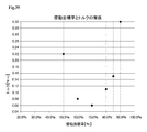
- FIG. 33 shows an experimental result regarding the relationship between the sliding area ratio of the resin-made thrust washer 20A and the torque (average torque).
- the experiment was performed on the resin-made thrust washer 20A according to the first configuration example having the non-communication oil groove 25a and the communication oil groove 25b as shown in FIG.
- the dimension corresponding to the width of the bottom portion 251 is 2.00 mm
- the dimension corresponding to the width of the oil groove 25 is 3.50 mm
- the height from the bottom portion 251 to the sliding surface 26 is 0.30 mm.
- the sliding area ratio is changed by changing the number of oil grooves 25 and the groove width, and the experiment is conducted. 33, the sliding area ratio of 100% (oil groove area ratio of 0%) corresponds to Comparative Example 1, and the sliding area ratio of 90% (oil groove area ratio of 10%) corresponds to Comparative Example 2, the sliding area ratio is 85% (oil groove area ratio is 15%) corresponds to Example 1, and the sliding area ratio is 80% (oil groove area).
- the ratio of 20%) corresponds to Example 2
- the sliding area ratio of 70% (oil groove area ratio of 30%) corresponds to Example 3
- the sliding area ratio of 60% (oil ratio).
- the groove area ratio of 40%) corresponds to Example 4
- the sliding area ratio of 50% (oil groove area ratio of 50%) corresponds to Comparative Example 3.
- Table 1 shows the torque (sliding load), the wear amount, and the determination results (torque determination and wear amount determination) corresponding to the experimental results of FIG.
- the resin-made thrust washer 20A having a torque (sliding load) of 0.7 N ⁇ m or less is indicated as “A” as satisfying the criterion of the low sliding load, and the torque (sliding load) is shown.
- the resin-made thrust washer 20A is indicated by “B” as not satisfying the standard of low sliding load.
- the resin-made thrust washers 20A having a wear amount of 20 ⁇ m or less are indicated by “A” as satisfying the criterion of the low wear amount, and the resin-made thrust washers 20A having a wear amount larger than 20 ⁇ m are shown. Is indicated as "B” as not satisfying the criterion of low wear amount.
- the sliding area ratio is in the range of 60% to 85% (that is, the oil groove area ratio is in the range of 15% to 40%)
- the average torque is 0.7 N ⁇ m or less. Since it becomes small, it can be said to be preferable.
- the sliding area ratio is in the range of 60% to 85% (that is, the oil groove area ratio is in the range of 15% to 40%)
- the wear amount is as small as 20 ⁇ m or less, which is preferable. I can say.
- FIG. 34 shows an experimental result regarding the relationship between the sliding area ratio of the resin thrust washer 20A and the torque (average torque), which was performed by attaching the resin thrust washer 20A according to the second configuration example.
- the dimension corresponding to the width of the bottom 251 is 0.80 mm
- the dimension corresponding to the width of the oil groove 25 is 2.10 mm
- the height from the bottom 251 to the sliding surface 26 is 0.30 mm. ..
- the sliding area ratio is changed by changing the number of oil grooves 25 and the groove width, and the experiment is conducted.
- the experimental conditions are the same as the experimental results shown in FIG. 33 and Table 1.
- the point where the sliding area ratio is 90% (oil groove area ratio is 10%) corresponds to Comparative Example 11
- the sliding area ratio is 85% (oil groove area ratio is 15%) corresponds to Example 11
- a sliding area ratio of 80% (oil groove area ratio 20%) corresponds to Example 12
- a sliding area ratio of 70% (oil groove area).
- the ratio of 30%) corresponds to Example 13
- the sliding area ratio of 60% (oil groove area ratio of 40%) corresponds to Example 14
- the groove area ratio is 50%) corresponds to Comparative Example 12.
- Table 2 shows the torque (sliding load), the wear amount, and the determination results (torque determination and wear amount determination) corresponding to the experimental results of FIG. 34.
- the torque determination in Table 2 the resin thrust washer 20A having a torque (sliding load) of 0.2 N ⁇ m or less is indicated by “A” as satisfying the criterion of the low sliding load, and the torque (sliding load) is shown.
- the resin-made thrust washer 20A having a wear amount of 30 ⁇ m or less is indicated by “A” as satisfying the criterion of the low wear amount, and the resin-made thrust washer 20A having a wear amount of greater than 30 ⁇ m is shown. Is indicated as "B” as not satisfying the criterion of low wear amount.
- the sliding area ratio is in the range of 60% to 85% (that is, the oil groove area ratio is in the range of 15% to 40%)
- the average torque is 0.2 N ⁇ m or less. Since it becomes small, it can be said to be preferable.
- the wear amount was as small as 20 ⁇ m or less in all the ranges. From these results, in the resin thrust washer 20A according to the second configuration example, the sliding area ratio is within the range of 60% to 85% (that is, the oil groove area ratio is within the range of 15% to 40%). It can be said to be preferable because it satisfies both the criteria of low sliding load and low wear amount.
- the sliding area ratio of 90% corresponds to Comparative Example 21
- the sliding area ratio of 85% corresponds to Example 21
- the sliding area ratio is 80% (oil groove area ratio is 20%)
- the sliding area ratio is 70% (oil groove area).
- the ratio of 30%) corresponds to Example 23
- the sliding area ratio of 60% corresponds to Example 24, and the sliding area ratio of 50% (oil ratio).
- the groove area ratio is 50%) corresponds to Comparative Example 22.
- Table 3 shows the torque (sliding load), the wear amount, and the determination results (torque determination and wear amount determination) corresponding to the experimental results of FIG.
- the judgment criterion for torque judgment is “A” when the torque is 0.2 N ⁇ m or less, “B” when the torque is larger than 0.2 N ⁇ m, and the criterion for the wear amount judgment is 30 ⁇ m or less. Is “A”, and “B” is larger than 30 ⁇ m, which is the same as in Table 2.
- the sliding area ratio is in the range of 60% to 85% (that is, the oil groove area ratio is in the range of 15% to 40%). Since it becomes small, it can be said to be preferable. In addition, if the sliding area ratio is within the range of 50% to 85% (that is, the oil groove area ratio is within the range of 15% to 50%), the wear amount is reduced to 30 ⁇ m or less, which is preferable. I can say. From these results, in the resin thrust washer 20B according to the fourth configuration example, the sliding area ratio is within the range of 60% to 85% (that is, the oil groove area ratio is within the range of 15% to 40%). It can be said to be preferable because it satisfies both the criteria of low sliding load and low wear amount.
- Example 4 the case where the groove angle of the oil groove 25 is 30 degrees corresponds to Example 31, the case where the groove angle of the oil groove 25 is 40 degrees corresponds to Example 32, and the groove angle of the oil groove 25 is Of 45 degrees corresponds to Example 33, the case where the groove angle of the oil groove 25 is 50 degrees corresponds to Example 34, and the case where the groove angle of the oil groove 25 is 55 degrees corresponds to Example 35.
- the case where the groove angle of the oil groove 25 is 60 degrees corresponds to Example 36.
- the judgment criterion for torque judgment is “A” when it is 0.2 N ⁇ m or less, and “B” when it is larger than 0.2 N ⁇ m, and the judgment criterion for wear amount judgment is 30 ⁇ m or less.
- the case is “A”, and the case of larger than 30 ⁇ m is “B”, which are the same as those in Table 2.
- the oil groove 25 having a groove angle of 30 degrees corresponds to Example 41
- the oil groove 25 having a groove angle of 40 degrees corresponds to Example 42
- the oil groove 25 has a groove angle of 40 degrees.
- the oil groove 25 having a groove angle of 50 degrees corresponds to Example 44
- the oil groove 25 having a groove angle of 55 degrees corresponds to Example 45.
- the case where the groove angle of the oil groove 25 is 60 degrees corresponds to Example 46.
- the judgment criterion for torque judgment is “A” when it is 0.2 N ⁇ m or less and “B” when it is larger than 0.2 N ⁇ m, and the judgment criterion for wear amount judgment is 30 ⁇ m or less.
- the case is “A”, and the case of larger than 30 ⁇ m is “B”, which are the same as those in Table 2.
- the sliding area ratio is 70% (that is, the oil groove area ratio is 30%)
- the groove angle of the oil groove 25 is in the range of 30 degrees to 60 degrees
- the average torque is 0.2 N ⁇ It can be said that it is preferable because the wear amount is reduced to m or less and the wear amount is reduced to 30 ⁇ m or less.
- Example 6 the case where the groove angle of the oil groove 25 is 30 degrees corresponds to Example 51, the case where the groove angle of the oil groove 25 is 40 degrees corresponds to Example 52, and the groove angle of the oil groove 25 is shown. Of 45 degrees corresponds to Example 53, the groove angle of the oil groove 25 of 50 degrees corresponds to Example 54, and the groove angle of the oil groove 25 of 55 degrees corresponds to Example 55. The case where the groove angle of the oil groove 25 is 60 degrees corresponds to Example 56.
- the judgment criterion for torque judgment is “A” when the torque is 0.2 N ⁇ m or less and “B” when the torque is larger than 0.2 N ⁇ m, and the criterion for the wear amount judgment is 30 ⁇ m or less.
- the case is “A”, and the case of larger than 30 ⁇ m is “B”, which are the same as those in Table 2.
- the oil groove 25 having a groove angle of 30 degrees corresponds to Example 61
- the oil groove 25 having a groove angle of 40 degrees corresponds to Example 62
- the oil groove 25 has a groove angle of 40 degrees.
- the groove angle of the oil groove 25 of 50 degrees corresponds to Example 64
- the groove angle of the oil groove 25 of 55 degrees corresponds to Example 65.
- the case where the groove angle of the oil groove 25 is 60 degrees corresponds to Comparative Example 61.
- the judgment criteria of the torque judgment in Table 7 are “A” when the torque is 0.2 N ⁇ m or less, “B” when the torque is larger than 0.2 N ⁇ m, and “C” when the resin-made thrust washer 20A cannot be manufactured. “A” when the wear amount is 30 ⁇ m or less, “B” when the wear amount is larger than 30 ⁇ m, and “C” when the resin-made thrust washer 20A cannot be manufactured. It is similar to the case. In addition, in the torque determination and the wear amount determination in Table 7, there is no determination “B”, and the determination “A” and the determination “C” exist.
- Comparative Example 61 when the groove angle is 60 degrees as described above, it interferes with other oil grooves 25 and cannot be manufactured. However, when the groove angle of the oil groove 25 is in the range of 30 degrees to 55 degrees, the average torque is reduced to 0.2 N ⁇ m or less and the wear amount is reduced to 30 ⁇ m or less, which is preferable.
- Example 71 the case where the groove angle of the oil groove 25 is 30 degrees corresponds to Example 71
- the case where the groove angle of the oil groove 25 is 40 degrees corresponds to Example 72
- the groove angle of the oil groove 25 is shown.
- Example 73 the case where the groove angle of the oil groove 25 is 50 degrees corresponds to Example 74
- Example 75 the case where the groove angle of the oil groove 25 is 55 degrees corresponds to Example 75.
- the case where the groove angle of the oil groove 25 is 60 degrees corresponds to Comparative Example 71.
- the judgment criteria for torque judgment in Table 8 are “A” when the torque is 0.2 N ⁇ m or less, “B” when the torque is 0.2 N ⁇ m or more, and “C” when the resin thrust washer 20B cannot be manufactured. “A” when the wear amount is 30 ⁇ m or less, “B” when the wear amount is larger than 30 ⁇ m, and “C” when the resin thrust washer 20B cannot be manufactured. It is similar to the case. In addition, in the torque determination and the wear amount determination in Table 8, there is no determination “B”, and the determination “A” and the determination “C” exist.
- Comparative Example 71 when such a groove angle is 60 degrees, it interferes with other oil grooves 25, and therefore cannot be manufactured. However, when the groove angle of the oil groove 25 is in the range of 30 degrees to 55 degrees, the average torque is reduced to 0.2 N ⁇ m or less and the wear amount is reduced to 30 ⁇ m or less, which is preferable.
- Example 81 the case where the groove angle of the oil groove 25 is 30 degrees corresponds to Example 81
- the case where the groove angle of the oil groove 25 is 40 degrees corresponds to Example 82
- the groove angle of the oil groove 25 is shown.
- the groove angle of the oil groove 25 of 50 degrees corresponds to Example 84
- the groove angle of the oil groove 25 of 55 degrees corresponds to Example 85.
- the case where the groove angle of the oil groove 25 is 60 degrees corresponds to Comparative Example 81.
- the judgment criteria for torque judgment in Table 9 are "A” when the torque is 0.2 Nm or less, “B” when the torque is 0.2 Nm or more, and “C” when the resin thrust washer 20B cannot be manufactured. “A” when the wear amount is 30 ⁇ m or less, “B” when the wear amount is larger than 30 ⁇ m, and “C” when the resin thrust washer 20B cannot be manufactured. It is similar to the case. In addition, in the torque determination and the wear amount determination in Table 9, there is no determination “B”, and the determination “A” and the determination “C” exist.
- Comparative Example 81 when such a groove angle is 60 degrees, it interferes with other oil grooves 25, and therefore cannot be manufactured. However, when the groove angle of the oil groove 25 is in the range of 30 degrees to 55 degrees, the average torque is reduced to 0.2 N ⁇ m or less and the wear amount is reduced to 30 ⁇ m or less, which is preferable.
- the case of the resin-made thrust washer 20A according to the third configuration example corresponds to Example 91
- the case of the resin-made thrust washer 20A according to the fifth configuration example corresponds to Example 92
- the sixth example The case of the resin-made thrust washer 20A according to the configuration example corresponds to Example 93
- the case of the resin-made thrust washer 20A according to the seventh configuration example corresponds to Example 94
- the resin-made thrust washer according to the eighth configuration example The case of 20A corresponds to Example 95
- the case of the resin-made thrust washer 20A according to the ninth configuration example corresponds to Example 96
- the case of the resin-made thrust washer 20A according to the tenth configuration example corresponds to Example 97.
- the case of the resin-made thrust washer 20A according to the eleventh configuration example corresponds to Example 98.
- the judgment criterion for torque judgment is “A” when 0.6 N ⁇ m or less and “B” when it is larger than 0.6 N ⁇ m, and the judgment criterion for wear amount judgment is 30 ⁇ m or less.
- the case is “A”
- the case larger than 30 ⁇ m is "B”.
- the average torque of the resin-made thrust washers 20A, 20B according to the third and fifth to eleventh configuration examples, and the resin-made thrust washers 20A, 20B having the oil grooves 25 on both surfaces thereof is shown.
- the resin thrust washer 20 having the above-described configuration is provided with the sliding surfaces 26 on the front surface and the back surface of the ring-shaped portion 21 that slide with other members (the mating members C1 and C2 and other thrust washers). Further, an oil groove 25, which is recessed from the sliding surface 26 and into which lubricating oil enters, is provided on at least one of the front surface and the back surface.
- An oil stop wall 28 that suppresses the oil is provided.
- the position of the oil stop wall 28 in the thickness direction of the resin thrust washer 20 is provided at the same position as the sliding surface 26, and the oil groove area ratio is provided within the range of 15% to 40%. There is.
- the lubricating oil that has entered the oil groove 25 is suppressed by the oil stop wall 28 from flowing out to the outer peripheral side of the resinous thrust washer 20. Therefore, on the surface side of the resinous thrust washer 20 where the oil groove 25 is present, an oil film of lubricating oil can be easily formed between the resinous thrust washer 20 and the other members (the mating members C1, C2 and other thrust washers). It will be possible. Further, the oil groove area ratio is provided within a range of 15% to 40%. Therefore, as is clear from the experimental results of Tables 32 to 34 and Tables 1 to 10, the surface side of the resinous thrust washer 20 on which the oil groove 25 is present and other members (the mating members C1, C2 and other members). It is possible to reduce the sliding load between the thrust washer and the thrust washer.
- a radial line L3 that passes through the intersecting position and extends in the radial direction is formed.
- the inclination angle ⁇ 1 formed by the center line L2 of the oil groove 25 is preferably provided within the range of 30 degrees to 55 degrees.
- the oil groove 25 guides the lubricating oil that has entered the oil groove 25 to the sliding surface 26 and the sliding surface 26 and other members (the mating members C1, C2 and other members). It is preferable that a dynamic pressure guide wall surface 254 for generating dynamic pressure is provided adjacent to the thrust washer).
- the oil groove 25 includes a first oil groove 25c inclined to one side with respect to the radial direction of the ring-shaped portion 21 and one side with respect to the radial direction of the ring-shaped portion 21. It is preferable that a second oil groove 25d that is inclined to the other side different from is provided, and that the first oil groove 25c and the second oil groove 25d be connected by the opening 27.
- the first oil groove 25c and the second oil groove 25d are respectively inclined on one side and the other side with the radial direction sandwiched therebetween. Therefore, on the surface side of the resin thrust washer 20B where the oil groove 25 exists, even if the resin thrust washer 20B rotates in either the clockwise direction or the counterclockwise direction, other members (the mating members C1, C2 and other members) It is possible to easily form an oil film of lubricating oil between the above and the thrust washer. Therefore, between the surface side of the resinous thrust washer 20B where the oil groove 25 is present and other members (the mating members C1, C2 and other thrust washers), the resinous thrust washer 20B does not matter in the rotating direction. It is possible to reduce the sliding load.
- first oil groove 25c and the second oil groove 25d are respectively provided with the bottom portions 251 that are the most recessed from the sliding surface 26, and the first oil groove 25c and the second oil groove 25d are provided.
- the wide tapered wall surface 252 guides the lubricating oil that has entered the oil groove 25 to the sliding surface 26, so that the resinous thrust washer 20 and other members (the mating members C1 and C2) are guided. It is possible to further reduce the sliding load between the and other thrust washers).
- first oil groove 25c and the second oil groove 25d are provided with curved wall surfaces 255 that are curved so that there is an inflection point from the bottom portion 251 toward the sliding surface 26.
- curved wall surfaces 255 that are curved so that there is an inflection point from the bottom portion 251 toward the sliding surface 26.
- the curved wall surface 255 guides the lubricating oil that has entered the oil groove 25 to the sliding surface 26, so that the resinous thrust washer 20 and other members (the mating members C1, C2 and other members) are guided. It is possible to further reduce the sliding load between the thrust washer and the thrust washer.
- the oil groove 25 having the same shape is provided on the front surface and the back surface of one resin thrust washer 20.
- the oil grooves 25 formed on the front surface and the back surface of one resin thrust washer 20 may have different shapes.
- at least one of the oil grooves 25 formed in the resin-made thrust washer 20 constituting the combined thrust washer 10 may have a shape different from the other shapes.
- an appropriate amount of lubricating oil is supplied according to the surface roughness of the surface of the resin-made thrust washer 20, the metal-made thrust washer, or the mating members C1 and C2 that faces the sliding surface 26 where the oil groove 25 exists.
- the shape of the oil groove 25 may be changed.
- the oil groove 25 along the radial direction and the oil groove 25 inclined at a predetermined inclination angle with respect to the radial direction may be mixed.
- An example of such a configuration is shown in FIGS. 36 and 37.
- the resin thrust washer 20B (twelfth configuration example) shown in FIG. 36 is similar to the resin thrust washer 20B according to the eighth configuration example shown in FIGS. 25 and 26, and has a convex curved surface portion 256, a wide groove portion 257, and It has a narrow groove portion 258.
- a communication oil groove 25b is provided in a portion between the set of the first oil groove 25c and the second oil groove 25d.
- a communication oil groove 25b intermediate communication oil groove as shown in FIG. 36 is provided. Is provided).
- the communication oil groove 25b is arranged between the openings 27 adjacent to each other in the circumferential direction of the ring-shaped portion 21 without interfering with the first oil groove 25c and the second oil groove 25d. Therefore, the non-communication oil groove 25a (the first oil groove 25c and the second oil groove 25d) for reducing the sliding load and the communication oil groove 25b for radiating heat to the outside are arranged on the sliding surface 26 in good balance. It is possible to realize the configuration.
- the non-communication oil groove 25a is provided with a wide groove portion 257 and a narrow groove portion 258 having a groove width narrower than that of the wide groove portion 257, and the narrow groove portion 258 is connected to the opening 27.
- the wide groove portion 257 is continuous with the wide groove portion 257 and is provided on the oil stop wall 28 side. Therefore, the sliding load can be favorably reduced.
- the oil stop wall 28 does not exist between the non-communication oil grooves 25a (the first oil groove 25c and the second oil groove 25d) that are separated from each other, and communicates with the outside of the ring-shaped portion 21.
- a communication oil groove 25b intermediate communication oil groove
- the non-communication oil groove 25a (the first oil groove 25c and the second oil groove 25d) for reducing the sliding load and the communication oil groove 25b for releasing the heat to the outside are formed on the sliding surface 26 in good balance. The arrangement can be realized.
- the resin thrust washer 20A (thirteenth configuration example) shown in FIG. 37 is similar to the resin thrust washer 20A according to the ninth configuration example shown in FIGS. 27 and 28, and the sliding projection 112, the communicating oil.
- the groove 113 and the dynamic pressure guide wall surface 254 are provided.
- a communication oil groove 25b is provided between the non-communication oil grooves 25a that are adjacent to each other in the circumferential direction.
- the non-communication oil grooves 25a and the communication oil grooves 25b are alternately provided in the circumferential direction of the ring-shaped portion 21. Therefore, both reduction of sliding load and good heat dissipation can be realized.
- the communication oil groove 25b there is communication between the communication oil groove 113 (adjacent communication oil groove) provided adjacent to the non-communication oil groove 25a and the non-communication oil groove 25a separated from each other.
- An oil groove 25b intermediate communication oil groove
- one communication oil groove 25b is arranged between the openings 27 that are adjacent to each other in the circumferential direction of the ring-shaped portion 21 without interfering with the first oil groove 25c and the second oil groove 25d.
- two or more communicating oil grooves 25b may be arranged between the openings 27 adjacent to each other in the circumferential direction.
- the communication oil groove 25b may not exist at one or more positions between the openings 27 that are adjacent to each other in the circumferential direction.
- the communication oil grooves 25b may be arranged regularly in the circumferential direction, but may be arranged irregularly. Further, in at least one of the configurations shown in FIGS. 36 and 37, the dynamic pressure guide wall surface 254 may not be provided.
- the present invention is merely an example of the above-described embodiments and dimensional examples, and may be applied to cases other than the above-mentioned embodiments and dimensional examples as long as they are within the above-mentioned sliding area ratio (oil groove area ratio). Of course, it can be included in the present invention.
Abstract
Provided is a thrust washer capable of reducing a sliding load. In a thrust washer 20, a front surface and a back surface of a ring-shaped part 21 is provided with sliding surfaces 26 that slide with other members, and further at least one of the front surface and the back surface is provided with oil grooves 25 which are recessed from the sliding surface 26 and into which lubricating oil enters. In the oil grooves 25, an opening portion 27 which is recessed from the sliding surface 26 and allows the lubricating oil to enter from an insertion hole 22 side is present on an inner circumferential edge side of the ring-shaped part 21. An outer circumferential edge portion of the ring-shaped part 21 in at least one of the oil grooves 25 is provided with an oil stop wall 28 that separates the oil groove 25 from the outside of the ring-shaped part 21 and prevents the lubricating oil that has entered into the oil groove 25 from flowing out to the outer circumferential side of the ring-shaped part 21. The position of the oil stop wall 28 in the thickness direction is set at about the same position as the sliding surface 26, and the sliding area ratio to a projection plane of the ring-shaped part in plan view is in the range of 60% to 85%.
Description
本発明は、スラストワッシャに関する。
The present invention relates to a thrust washer.
クラッチ装置、歯車機構やコンプレッサ等のような機械装置においては、たとえば特許文献1から特許文献4に示すような、スラストワッシャが取り付けられる場合がある。特許文献1に開示のスラストワッシャには、油溝が挿通孔から外周側に向かうように形成されている。また、特許文献2に開示のスラストワッシャには、スラストワッシャの内周面と外周面とを連通する第1油路と、内周面には開口するものの外周面に開口しない行き止まりの第2油路とが設けられている。
In mechanical devices such as clutch devices, gear mechanisms, compressors, etc., thrust washers as shown in, for example, Patent Documents 1 to 4 may be attached. In the thrust washer disclosed in Patent Document 1, an oil groove is formed so as to extend from the insertion hole toward the outer peripheral side. Further, the thrust washer disclosed in Patent Document 2 includes a first oil passage that connects the inner peripheral surface and the outer peripheral surface of the thrust washer, and a dead end second oil that opens on the inner peripheral surface but does not open on the outer peripheral surface. And a road is provided.
また、特許文献3に開示のスラストワッシャには、円弧状の給油溝やV字形の給油溝が設けられている。また、特許文献4に開示のスラストワッシャには、内周縁から外周縁まで延びる第1油溝および第2油溝と、第1油溝と第2油溝とを連通させる連通油溝とを有する構成が開示されている。
Also, the thrust washer disclosed in Patent Document 3 is provided with an arc-shaped oil supply groove and a V-shaped oil supply groove. Further, the thrust washer disclosed in Patent Document 4 has a first oil groove and a second oil groove extending from the inner peripheral edge to the outer peripheral edge, and a communication oil groove communicating the first oil groove and the second oil groove. A configuration is disclosed.
スラストワッシャには、対向する相手材が存在するものの、潤滑油がスラストワッシャと相手材との間に介在する。そのような環境下においては、スラストワッシャの潤滑状態は、ストライベック線図における混合潤滑領域におけるものと想定され、一部は潤滑油の油膜によりスラストワッシャが相手材と隔てられているものの、一部はスラストワッシャが相手材と直接接触していると考えられる。このような混合潤滑領域においては、どのようなスラストワッシャの構成にすれば、摺動負荷の低減が図れるのかは詳しく分かっていない。その一方で、近年、スラストワッシャにおいては、摺動面における摺動負荷の低減の要求が一層求められている。したがって、上述した特許文献1から4に開示のスラストワッシャよりも、一段と高い摺動負荷の低減が要求されている。
Despite the fact that the thrust washer has an opposing mating material, the lubricating oil is present between the thrust washer and the mating material. In such an environment, the lubrication state of the thrust washer is assumed to be in the mixed lubrication region in the Stribeck diagram, and although part of the thrust washer is separated from the mating material by the oil film of lubricating oil, It is considered that the thrust washer is in direct contact with the mating material. In such a mixed lubrication region, it is not known in detail what kind of structure of the thrust washer can reduce the sliding load. On the other hand, in recent years, in thrust washers, there has been a further demand for reducing the sliding load on the sliding surface. Therefore, it is required to further reduce the sliding load as compared with the thrust washers disclosed in Patent Documents 1 to 4 described above.
本発明は上記の事情にもとづきなされたもので、その目的は、摺動負荷の低減を図ることが可能なスラストワッシャを提供するものである。
The present invention has been made based on the above circumstances, and an object thereof is to provide a thrust washer capable of reducing a sliding load.
上記課題を解決するために、本発明の第1の観点によると、挿通孔を囲むリング状部を有する樹脂を含む材料からなるスラストワッシャであって、スラストワッシャには、リング状部の表面と裏面に他の部材と摺動する摺動面が設けられ、さらに表面と裏面の少なくとも一方に摺動面から凹むと共に潤滑油が入り込む油溝が設けられていて、油溝には、摺動面よりも凹んでいると共に挿通孔側から潤滑油が入り込むことを可能とする開口部がリング状部の内周端部側に存在していて、少なくとも1つの油溝のリング状部の外周端部には、油溝とリング状部の外側とを隔てると共に油溝に入り込んだ潤滑油がリング状部の外周側に流出するのを抑制する油止壁が設けられていて、該油止壁のスラストワッシャの厚み方向における位置は摺動面と同程度の位置に設けられていて、リング状部の平面図における投影面に対して摺動面が占める摺動面積率は、60~85%の範囲内に設けられている、ことを特徴とするスラストワッシャが提供される。
In order to solve the above problems, according to a first aspect of the present invention, there is provided a thrust washer made of a material containing a resin having a ring-shaped portion surrounding an insertion hole, wherein the thrust washer has a surface of the ring-shaped portion. A sliding surface that slides with other members is provided on the back surface, and at least one of the front surface and the back surface is provided with an oil groove that is recessed from the sliding surface and into which lubricating oil enters. Has an opening on the inner peripheral end side of the ring-shaped portion, which is recessed relative to the inner periphery of the ring-shaped portion and allows the lubricating oil to enter from the insertion hole side, and the outer peripheral end portion of the ring-shaped portion of at least one oil groove. Is provided with an oil stop wall that separates the oil groove from the outside of the ring-shaped portion and that prevents the lubricating oil that has entered the oil groove from flowing out to the outer peripheral side of the ring-shaped portion. The position of the thrust washer in the thickness direction is approximately the same as that of the sliding surface, and the sliding area ratio of the sliding surface to the projection surface in the plan view of the ring-shaped portion is 60 to 85%. A thrust washer is provided that is provided within the range.
また、本発明の他の側面は、上述の発明において、油溝の中心線とリング状部の径方向における中央線とが交差する交差位置において、その交差位置を通ると共に径方向に沿う径方向線に対して油溝の中心線がなす傾斜角度は、30度から55度の範囲内に設けられている、ことが好ましい。
Further, another aspect of the present invention is, in the above-mentioned invention, at an intersecting position where the center line of the oil groove intersects with the center line in the radial direction of the ring-shaped portion, the radial direction passing through the intersecting position and along the radial direction. The inclination angle formed by the center line of the oil groove with respect to the line is preferably provided within the range of 30 degrees to 55 degrees.
また、本発明の他の側面は、上述の発明において、油溝には、当該油溝に入り込んだ潤滑油を摺動面にガイドさせて該摺動面と他の部材との間に動圧を生じさせるための動圧用ガイド壁面が隣接して設けられている、ことが好ましい。
In another aspect of the present invention, in the above-mentioned invention, the oil groove is configured to guide the lubricating oil that has entered the oil groove to a sliding surface so that a dynamic pressure is applied between the sliding surface and another member. It is preferable that the dynamic pressure guide wall surface for causing the above is provided adjacently.
また、本発明の他の側面は、上述の発明において、油溝には、リング状部の径方向に対して一方側に傾斜している第1油溝と、リング状部の径方向に対して一方側とは異なる他方側に傾斜している第2油溝とが設けられていて、第1油溝と第2油溝は、開口部で連結されている、ことが好ましい。
Further, another aspect of the present invention is, in the above-mentioned invention, in which the oil groove has a first oil groove inclined to one side with respect to a radial direction of the ring-shaped portion and a radial direction of the ring-shaped portion. It is preferable that a second oil groove that is inclined to the other side different from the one side is provided, and that the first oil groove and the second oil groove are connected by an opening.
また、本発明の他の側面は、上述の発明において、第1油溝および第2油溝には、摺動面から最も凹んだ底部がそれぞれ設けられていて、第1油溝および第2油溝には、該第1油溝および該第2油溝で囲まれない外側に位置する部位に、摺動面に向かって直線状に傾斜するテーパ壁面が設けられていて、テーパ壁面は、底部よりも幅広に設けられている、ことが好ましい。
Further, another aspect of the present invention is the above-described invention, wherein the first oil groove and the second oil groove are respectively provided with bottom portions that are most recessed from the sliding surface, and the first oil groove and the second oil groove are provided. The groove is provided with a taper wall surface that is linearly inclined toward the sliding surface at a portion located outside that is not surrounded by the first oil groove and the second oil groove. It is preferable that the width is wider than that.
また、本発明の他の側面は、上述の発明において、第1油溝および第2油溝には、底部から摺動面に向かうと共に変曲点が存在するように湾曲している湾曲壁面が設けられている、ことが好ましい。
Another aspect of the present invention is the above-described invention, wherein the first oil groove and the second oil groove have curved wall surfaces that are curved so that an inflection point exists from the bottom toward the sliding surface. It is preferably provided.
また、本発明の他の側面は、上述の発明において、油溝には、油止壁によりリング状部の外側と隔てられた非連通油溝と、油止壁が存在せずにリング状部の外側と連通している連通油溝とが設けられている、ことが好ましい。
Further, another aspect of the present invention is, in the above-mentioned invention, in the oil groove, a non-communication oil groove separated from the outside of the ring-shaped portion by an oil stop wall, and the ring-shaped portion without the oil stop wall. It is preferable that a communication oil groove communicating with the outside of the is provided.
また、本発明の他の側面は、上述の発明において、非連通油溝と連通油溝とは、リング状部の周方向において交互に設けられている、ことが好ましい。
Further, in another aspect of the present invention, in the above-mentioned invention, it is preferable that the non-communication oil groove and the communication oil groove are provided alternately in the circumferential direction of the ring-shaped portion.
また、本発明の他の側面は、上述の発明において、連通油溝には、非連通油溝に隣接して設けられている隣接連通油溝と、互いに離間している非連通油溝の間に存在する中間連通油溝とが設けられている、ことが好ましい。
Further, another aspect of the present invention is, in the above-mentioned invention, in the communication oil groove, between an adjacent communication oil groove provided adjacent to the non-communication oil groove and a non-communication oil groove separated from each other. It is preferable that the intermediate communication oil groove existing in 1) is provided.
また、本発明の他の側面は、上述の発明において、油溝には、油止壁によりリング状部の外側と隔てられた非連通油溝と、油止壁が存在せずにリング状部の外側と連通している連通油溝とが設けられていて、連通油溝は、第1油溝と第2油溝に干渉しない状態でリング状部の周方向において隣り合っている開口部の間の部位に配置されている、ことが好ましい。
Further, another aspect of the present invention is, in the above-mentioned invention, in the oil groove, a non-communication oil groove separated from the outside of the ring-shaped portion by an oil stop wall, and the ring-shaped portion without the oil stop wall. Is provided with a communication oil groove communicating with the outside of the first oil groove, and the communication oil groove is formed in an opening portion adjacent to each other in the circumferential direction of the ring-shaped portion without interfering with the first oil groove and the second oil groove. It is preferable that it is arranged in a region between them.
また、本発明の他の側面は、上述の発明において、非連通油溝には、幅広溝部と、該幅広溝部よりも溝幅の狭い幅狭溝部とが設けられていて、幅狭溝部は、開口部に接続されていて、幅広溝部は、幅狭溝部と連続していると共に油止壁側に設けられている、ことが好ましい。
Further, in another aspect of the present invention, in the above-mentioned invention, the non-communication oil groove is provided with a wide groove portion and a narrow groove portion having a groove width narrower than the wide groove portion, and the narrow groove portion is It is preferable that the wide groove portion is connected to the opening portion, is continuous with the narrow groove portion, and is provided on the oil stop wall side.
また、本発明の他の側面は、上述の発明において、外側と連通している中間連通油溝とが設けられている、ことが好ましい。
Further, in another aspect of the present invention, in the above invention, it is preferable that an intermediate communication oil groove communicating with the outside is provided.
また、本発明の他の側面は、上述の発明において、リング状部の内周側には、前記開口部へ前記潤滑油をガイドする油掬い面が設けられていて、油掬い面は、リング状部の軸方向に対して傾斜して設けられていて、開口部は、油掬い面を窪ませることで構成されている、ことが好ましい。
In another aspect of the present invention, in the above-mentioned invention, an oil scooping surface that guides the lubricating oil to the opening is provided on the inner peripheral side of the ring-shaped portion, and the oil scooping surface is a ring. It is preferable that the opening is provided so as to be inclined with respect to the axial direction of the shaped portion, and the opening is formed by recessing the oil scooping surface.
また、本発明の他の側面は、上述の発明において、油掬い面の内周端部から摺動面までの高さは、油溝のうち摺動面から最も凹んだ底部から摺動面までの高さに対して、2倍以上の寸法に設けられている、ことが好ましい。
Another aspect of the present invention is the above-mentioned invention, wherein the height from the inner peripheral end of the oil scooping surface to the sliding surface is from the bottom of the oil groove, which is the most recessed to the sliding surface, to the sliding surface. It is preferable that the size is provided at least twice as large as the height.
また、本発明の他の側面は、上述の発明において、リング状部には、リング状部の内径側から外径側に向かうように凹ませた油導入溝が設けられていて、油導入溝の溝底部がリング状部の軸方向に対してなす傾斜角度は、油掬い面が軸方向に対してなす傾斜角度よりも小さく設けられていて、油導入溝と油掬い面との間には段差が設けられている、ことが好ましい。
Another aspect of the present invention is the above-described invention, wherein the ring-shaped portion is provided with an oil introduction groove that is recessed from the inner diameter side of the ring-shaped portion toward the outer diameter side. The inclination angle formed by the groove bottom of the ring-shaped portion with respect to the axial direction is smaller than the inclination angle formed by the oil scooping surface with respect to the axial direction, and between the oil introduction groove and the oil scooping surface. It is preferable that a step is provided.
また、本発明の他の側面は、上述の発明において、油導入溝のうち、油掬い面との境界壁の少なくとも一部は、リング状部の径方向に対して傾斜して設けられている、ことが好ましい。
Further, according to another aspect of the present invention, in the above-mentioned invention, at least a part of a boundary wall between the oil introduction groove and the oil scooping surface is provided to be inclined with respect to a radial direction of the ring-shaped portion. , Is preferred.
本発明によると、摺動負荷の低減を図ることが可能なスラストワッシャを提供することができる。
According to the present invention, it is possible to provide a thrust washer capable of reducing sliding load.
以下、本発明の一実施の形態に係る、樹脂を含む材料からなるスラストワッシャとしての樹脂製スラストワッシャ20と、その樹脂製スラストワッシャ20を用いた組合せスラストワッシャ10について、図面に基づいて説明する。
Hereinafter, a resin-made thrust washer 20 as a thrust washer made of a resin-containing material and a combined thrust washer 10 using the resin-made thrust washer 20 according to an embodiment of the present invention will be described with reference to the drawings. ..
[1.組合せスラストワッシャ10の全体的な構成について]
組合せスラストワッシャ10は、たとえば車両のトランスミッション装置、車両のエアーコンディショナ装置のコンプレッサに組み込まれるものである。この組合せスラストワッシャ10の構成を、図1に示す。図1は、組合せスラストワッシャ10の構成を示す斜視図である。 [1. About the overall configuration of the combined thrust washer 10]
The combinedthrust washer 10 is incorporated in, for example, a transmission device of a vehicle or a compressor of an air conditioner device of a vehicle. The structure of this combined thrust washer 10 is shown in FIG. FIG. 1 is a perspective view showing the configuration of the combined thrust washer 10.
組合せスラストワッシャ10は、たとえば車両のトランスミッション装置、車両のエアーコンディショナ装置のコンプレッサに組み込まれるものである。この組合せスラストワッシャ10の構成を、図1に示す。図1は、組合せスラストワッシャ10の構成を示す斜視図である。 [1. About the overall configuration of the combined thrust washer 10]
The combined
図1に示すように、本実施の形態の組合せスラストワッシャ10は、3枚のスラストワッシャS1,S2,S3を備えている。3枚のスラストワッシャS1,S2,S3を備える組合せスラストワッシャ10は、相手材C1,C2の間に位置していて、スラスト方向の荷重を受ける状態となっている。
As shown in FIG. 1, the combined thrust washer 10 of the present embodiment includes three thrust washers S1, S2, S3. The combined thrust washer 10 including the three thrust washers S1, S2, S3 is located between the mating members C1, C2 and is in a state of receiving a load in the thrust direction.
なお、組合せスラストワッシャ10と相手材C1,C2とが設けられる環境は、潤滑油が供給される環境下ではある。しかしながら、本実施の形態に係る組合せスラストワッシャ10に辿り着くまでの各種の実験結果等におけるスラストワッシャの摺動痕や各種の実験結果等で測定された摺動負荷から推定すると、組合せスラストワッシャ10が使用される環境の潤滑状態は、ストライベック線図における混合潤滑領域におけるものと想定される。したがって、スラストワッシャと相手材との間の一部には油膜が介在すると共に、スラストワッシャの一部は相手材と直接接触していると推測される。
Note that the environment in which the combined thrust washer 10 and the mating members C1 and C2 are provided is the environment in which the lubricating oil is supplied. However, when estimated from sliding marks of the thrust washer in various experimental results, etc. until reaching the combined thrust washer 10 according to the present embodiment and sliding loads measured by various experimental results, the combined thrust washer 10 is obtained. The lubrication state of the environment in which is used is assumed to be in the mixed lubrication region in the Stribeck diagram. Therefore, it is presumed that an oil film is present between a part of the thrust washer and the mating member, and a part of the thrust washer is in direct contact with the mating member.
上述のスラストワッシャS1,S2,S3は、(1)樹脂を材質とする樹脂製スラストワッシャ20(図2、図3等参照)、(2)金属を材質とする金属製スラストワッシャの中から、少なくとも1枚の樹脂製スラストワッシャ20を備えるように構成される。具体的には、図1に示す組合せスラストワッシャ10において、相手材C1側と相手材C2側に樹脂製スラストワッシャ20を配置して中央に金属製スラストワッシャを配置しても良く、相手材C1側のみに樹脂製スラストワッシャ20を配置して残りを金属製スラストワッシャとしても良く、相手材C2側のみに樹脂製スラストワッシャ20を配置して残りを金属製スラストワッシャとしても良い。また、相手材C1側のみに金属製スラストワッシャを配置して残り2枚を樹脂製スラストワッシャ20としても良く、相手材C2側のみに金属製スラストワッシャを配置して残り2枚を樹脂製スラストワッシャ20としても良く、相手材C1側と相手材C2側の両方に金属製スラストワッシャをそれぞれ配置して中央に樹脂製スラストワッシャ20を配置しても良い。また、3枚の上述のスラストワッシャS1,S2,S3を全て樹脂製スラストワッシャ20としても良い。
The above thrust washers S1, S2, S3 include (1) resin-made thrust washers 20 made of resin (see FIGS. 2 and 3) and (2) metal-made thrust washers made of metal. It is configured to include at least one resin thrust washer 20. Specifically, in the combined thrust washer 10 shown in FIG. 1, the resin thrust washer 20 may be arranged on the mating member C1 side and the mating member C2 side and the metal thrust washer may be arranged at the center. The resin thrust washer 20 may be disposed only on the side and the rest may be a metal thrust washer, and the resin thrust washer 20 may be disposed only on the mating material C2 side and the rest may be a metal thrust washer. Further, the metal thrust washers may be arranged only on the mating member C1 side and the remaining two may be resin thrust washers 20, and the metal thrust washers may be arranged only on the mating member C2 side and the remaining two are resin thrust washers. The washer 20 may be used, or the metal thrust washers may be arranged on both the mating member C1 side and the mating member C2 side, and the resin thrust washer 20 may be arranged at the center. Further, all of the above three thrust washers S1, S2, S3 may be resin thrust washers 20.
[2.樹脂製スラストワッシャ20の構成について]
まず、組合せスラストワッシャ10を構成する樹脂製スラストワッシャ20の構成について説明する。図2は、図1に示す組合せスラストワッシャ10を構成する樹脂製スラストワッシャ20の構成を示す平面図であり、油溝25が非連通油溝25aと連通油溝25bから構成される状態を示す図である。また、図3は、図1に示す組合せスラストワッシャ10を構成する樹脂製スラストワッシャ20の構成を示す平面図であり、傾斜角度の異なる2本の油溝25が開口部27で連結されている構成を示す図である。図3に示す構成では、傾斜角度の異なる2本の油溝25が開口部27において連結されることで、油溝25の全体は略V字を描くような形態となっている。 [2. Configuration of resin-made thrust washer 20]
First, the configuration of the resin thrust washer 20 that constitutes the combinedthrust washer 10 will be described. FIG. 2 is a plan view showing the configuration of the resin-made thrust washer 20 that constitutes the combined thrust washer 10 shown in FIG. It is a figure. 3 is a plan view showing the structure of the resin-made thrust washer 20 that constitutes the combined thrust washer 10 shown in FIG. 1. Two oil grooves 25 having different inclination angles are connected by an opening 27. It is a figure which shows a structure. In the configuration shown in FIG. 3, two oil grooves 25 having different inclination angles are connected at the opening 27, so that the entire oil groove 25 has a substantially V-shaped configuration.
まず、組合せスラストワッシャ10を構成する樹脂製スラストワッシャ20の構成について説明する。図2は、図1に示す組合せスラストワッシャ10を構成する樹脂製スラストワッシャ20の構成を示す平面図であり、油溝25が非連通油溝25aと連通油溝25bから構成される状態を示す図である。また、図3は、図1に示す組合せスラストワッシャ10を構成する樹脂製スラストワッシャ20の構成を示す平面図であり、傾斜角度の異なる2本の油溝25が開口部27で連結されている構成を示す図である。図3に示す構成では、傾斜角度の異なる2本の油溝25が開口部27において連結されることで、油溝25の全体は略V字を描くような形態となっている。 [2. Configuration of resin-made thrust washer 20]
First, the configuration of the resin thrust washer 20 that constitutes the combined
以下の説明では、図2に示すような、一の油溝25が他の油溝25と略V字を描くように連結されていない構成の樹脂製スラストワッシャ20を、樹脂製スラストワッシャ20Aと称呼する。また、図3に示すような略V字を描くように連結されている油溝25を有する樹脂製スラストワッシャ20を、樹脂製スラストワッシャ20Bと称呼する。しかしながら、樹脂製スラストワッシャ20Aと樹脂製スラストワッシャ20Bを区別する必要がない場合には、単に樹脂製スラストワッシャ20と称呼する。
In the following description, as shown in FIG. 2, a resin-made thrust washer 20 configured such that one oil groove 25 is not connected to another oil groove 25 in a substantially V-shape is referred to as a resin-made thrust washer 20A. Call. Further, the resin-made thrust washer 20 having the oil groove 25 connected so as to draw a substantially V-shape as shown in FIG. 3 is referred to as a resin-made thrust washer 20B. However, when it is not necessary to distinguish between the resin thrust washer 20A and the resin thrust washer 20B, the resin thrust washer 20 is simply referred to as the resin thrust washer 20.
樹脂製スラストワッシャ20は、その材質を(1)樹脂基材単独、(2)樹脂基材に繊維材を混合したもの、(3)樹脂基材に充填材を混合したもの、(4)樹脂基材に繊維材と充填材を混合したもの、のいずれかとしている。以下、樹脂基材、繊維材、充填材について、それぞれ述べる。
The resin-made thrust washers 20 are made of (1) a resin base material alone, (2) a resin base material mixed with a fibrous material, (3) a resin base material mixed with a filler, and (4) a resin. Either the base material mixed with the fibrous material and the filler is used. The resin base material, the fiber material, and the filler will be described below.
[2.1.樹脂基材について]
樹脂基材は、4フッ化エチレン樹脂(PTFE)、ポリアミド樹脂(PA)、ポリアミドイミド樹脂(PAI)、ポリイミド樹脂(PI)、ポリベンゾイミダゾール樹脂(PBI)、芳香族ポリエーテルケトン類(PAEK)、変性ポリエーテルケトン樹脂、ポリフェニレンサルファイド樹脂(PPS)、液晶ポリマー、フェノール樹脂、ポリエチレン樹脂、ポリスチレン樹脂、アクリル樹脂、アクリロニトリルブタジエン・スチレン樹脂、ポリアセタール樹脂、ポリカーボネート樹脂、ポリエーテルサルフォン樹脂(PES)、ポリエーテルイミド樹脂(PEI)のいずれか、またはこれらの中から複数を選択して混合した混合物(ポリマーアロイや共重合が含まれる)となっている。 [2.1. About resin base material]
The resin base material is tetrafluoroethylene resin (PTFE), polyamide resin (PA), polyamideimide resin (PAI), polyimide resin (PI), polybenzimidazole resin (PBI), aromatic polyetherketones (PAEK). , Modified polyetherketone resin, polyphenylene sulfide resin (PPS), liquid crystal polymer, phenol resin, polyethylene resin, polystyrene resin, acrylic resin, acrylonitrile butadiene/styrene resin, polyacetal resin, polycarbonate resin, polyether sulfone resin (PES), It is either a polyetherimide resin (PEI) or a mixture (including a polymer alloy and a copolymer) in which a plurality of them are selected and mixed.
[2.2.繊維材について]
繊維材は、平均繊維長がたとえば0.0001mm~5mm程度の長さの補強繊維であり、その繊維物は、炭素繊維、ガラス繊維、チタン酸カリウム繊維等のような無機繊維を素材とするもの、アラミド繊維、フッ素繊維等のような有機繊維を素材とするものがあるが、これらに限らない。また、上述の繊維材の中から少なくとも1つの繊維材を選択すると共に、その他の材質の繊維材を選択して混合しても良い。 [2.2. About fiber materials]
The fibrous material is a reinforcing fiber having an average fiber length of, for example, about 0.0001 mm to 5 mm, and the fibrous material is made of inorganic fiber such as carbon fiber, glass fiber, potassium titanate fiber and the like. , Aramid fiber, fluorine fiber, etc. are used as a material, but not limited to these. Further, at least one fiber material may be selected from the above-mentioned fiber materials, and fiber materials of other materials may be selected and mixed.
なお、繊維材がガラス繊維の場合には、その製品当たりの混合率の重量割合は1~40重量%が好適である。また、繊維材が炭素繊維またはアラミド繊維の場合には、その製品当たりの混合率の重量割合は1~45重量%が好適である。また、繊維材がフッ素繊維の場合には、その製品当たりの混合率の重量割合は5~55重量%が好適である。また、繊維材がチタン酸カリウムの場合には、その製品当たりの混合率の重量割合は0.1~5重量%が好適である。
When the fiber material is glass fiber, the weight ratio of the mixing ratio per product is preferably 1 to 40% by weight. When the fiber material is carbon fiber or aramid fiber, the weight ratio of the mixing ratio per product is preferably 1 to 45% by weight. Further, when the fiber material is a fluorine fiber, the weight ratio of the mixing ratio per product is preferably 5 to 55% by weight. When the fibrous material is potassium titanate, the weight ratio of the mixing ratio per product is preferably 0.1 to 5% by weight.
[2.3.充填材について]
充填材は、4フッ化エチレン樹脂(PTFE)、硫化マンガン(MnS)、二硫化モリブデン(MoS2 )、グラファイト、炭酸カルシウム(CaCo3 )、酸化チタン、メラミンシアヌレート(MCA)のうちのいずれか、またはこれらの中から複数を選択して混合されたものである。 [2.3. Filler]
The filler is any one of tetrafluoroethylene resin (PTFE), manganese sulfide (MnS), molybdenum disulfide (MoS 2 ), graphite, calcium carbonate (CaCo 3 ), titanium oxide, and melamine cyanurate (MCA). , Or a mixture of a plurality of these selected.
[2.4.樹脂製スラストワッシャ20の表面処理について]
樹脂製スラストワッシャ20の表面処理(ここでの表面処理は、表面改質処理も含む)は、エポキシシラン(信越シリコーン社製)を用いた表面改質処理、チタネート系・アルミネート系カップリング剤(具体的には、ビスー(ジオクチルパイロホスフェート)イソプロポキシチタネート;味の素ファインテクノ社製:商品名38S)を用いた表面改質処理、ビスー(ジオクチルパイロホスフェート)オキシアセテートチタネート;商品名138S;味の素ファインテクノ社製)を用いた表面改質処理、商品名55(味の素ファインテクノ社製)、アセトアルコキシアルミニウムジイソプロピレート商品名AL-M;味の素ファインテクノ社製)を用いた表面改質処理が挙げられるが、これらのうちのいずれか、またはこれらの中から複数を選択して表面処理(表面改質処理)を行っても良い。また、上記の表面処理(表面改質処理)に代えて、コロナ放電またはイオンプラズマ放電を用いたカップリング処理を行うようにしても良く、上記の表面改質処理に代えてDLC処理またはMoコーティングを行うようにしても良い。特に、DLC処理は、摺動部位において、低摩擦化および耐摩耗性の向上を図ることが可能であり、好ましい。 [2.4. Surface Treatment of Resin Thrust Washer 20]
The surface treatment of the resin-made thrust washer 20 (including the surface modification treatment here) is a surface modification treatment using epoxysilane (manufactured by Shin-Etsu Silicone Co., Ltd.), a titanate-aluminate-based coupling agent. (Specifically, surface modification treatment using bis-(dioctyl pyrophosphate)isopropoxy titanate; Ajinomoto Fine Techno Co., Ltd.: trade name 38S), bis-(dioctyl pyrophosphate) oxyacetate titanate; trade name 138S; Ajinomoto Fine Surface modification treatment using TECHNO Co., Ltd., surface modification treatment using trade name 55 (manufactured by Ajinomoto Fine-Techno Co., Ltd.), acetoalkoxy aluminum diisopropylate trade name AL-M; manufactured by Ajinomoto Fine-Techno Co. However, any one of them or a plurality of them may be selected for the surface treatment (surface modification treatment). Further, instead of the above surface treatment (surface modification treatment), a coupling treatment using corona discharge or ion plasma discharge may be performed, and instead of the above surface modification treatment, DLC treatment or Mo coating. May be performed. In particular, the DLC treatment is preferable because it can reduce friction and improve wear resistance at the sliding portion.
[3.樹脂製スラストワッシャ20Aの具体的構成について]
(1)樹脂製スラストワッシャ20Aの第1構成例について
以下、樹脂製スラストワッシャ20Aの具体的構成について説明する。まず、第1構成例に係る樹脂製スラストワッシャ20Aについて説明する。図2に示すように、樹脂製スラストワッシャ20Aには、挿通孔22を覆うように、リング状部21が設けられている。このリング状部21の内周側(挿通孔22側)には、潤滑油を油溝25に導入するための油導入溝23が設けられていて、その油導入溝23は、挿通孔22側から外径側に向かうように内周壁を凹ませた形状に設けられている。すなわち、挿通孔22には、不図示の回転シャフトが配置されるが、油導入溝23が存在しないと、回転シャフトに沿った潤滑油の供給が阻害され、それによって油溝25に潤滑油が十分に供給されない虞がある。しかしながら、油導入溝23が存在することで、潤滑油を油溝25に良好に導入することが可能となっている。 [3. Specific configuration of resin-made thrust washer 20A]
(1) First Configuration Example of Resin Thrust Washer 20A Hereinafter, a specific configuration of the resin thrust washer 20A will be described. First, the resin-made thrust washer 20A according to the first configuration example will be described. As shown in FIG. 2, the resin-made thrust washer 20A is provided with a ring-shapedportion 21 so as to cover the insertion hole 22. An oil introduction groove 23 for introducing lubricating oil into the oil groove 25 is provided on the inner peripheral side (the insertion hole 22 side) of the ring-shaped portion 21, and the oil introduction groove 23 is provided on the insertion hole 22 side. Is provided in a shape in which the inner peripheral wall is recessed so as to face the outer diameter side. That is, although a rotary shaft (not shown) is arranged in the insertion hole 22, if the oil introduction groove 23 does not exist, the supply of the lubricating oil along the rotary shaft is hindered, and the lubricating oil is thus supplied to the oil groove 25. There is a possibility that the supply may not be sufficient. However, the presence of the oil introduction groove 23 makes it possible to introduce the lubricating oil into the oil groove 25 satisfactorily.
(1)樹脂製スラストワッシャ20Aの第1構成例について
以下、樹脂製スラストワッシャ20Aの具体的構成について説明する。まず、第1構成例に係る樹脂製スラストワッシャ20Aについて説明する。図2に示すように、樹脂製スラストワッシャ20Aには、挿通孔22を覆うように、リング状部21が設けられている。このリング状部21の内周側(挿通孔22側)には、潤滑油を油溝25に導入するための油導入溝23が設けられていて、その油導入溝23は、挿通孔22側から外径側に向かうように内周壁を凹ませた形状に設けられている。すなわち、挿通孔22には、不図示の回転シャフトが配置されるが、油導入溝23が存在しないと、回転シャフトに沿った潤滑油の供給が阻害され、それによって油溝25に潤滑油が十分に供給されない虞がある。しかしながら、油導入溝23が存在することで、潤滑油を油溝25に良好に導入することが可能となっている。 [3. Specific configuration of resin-made thrust washer 20A]
(1) First Configuration Example of Resin Thrust Washer 20A Hereinafter, a specific configuration of the resin thrust washer 20A will be described. First, the resin-made thrust washer 20A according to the first configuration example will be described. As shown in FIG. 2, the resin-made thrust washer 20A is provided with a ring-shaped
また、リング状部21の内周側(挿通孔22側)には、油掬い面24が設けられている。油掬い面24は、油導入溝23から導入された潤滑油を、リング状部21の周方向にガイドする部分である。この油掬い面24は、リング状部21の内周側を、たとえばテーパ状や曲面状に加工することで形成される。
Also, an oil scooping surface 24 is provided on the inner peripheral side of the ring-shaped portion 21 (the insertion hole 22 side). The oil scooping surface 24 is a portion that guides the lubricating oil introduced from the oil introducing groove 23 in the circumferential direction of the ring-shaped portion 21. The oil scooping surface 24 is formed by processing the inner peripheral side of the ring-shaped portion 21 into, for example, a tapered shape or a curved surface shape.
また、リング状部21には、油溝25が設けられている。図4は、第1構成例に係る樹脂製スラストワッシャ20Aの構成を示す部分的な平面図である。図2および図4に示すように、油溝25は、リング状部21のうち、他の部材(相手材C1,C2、他の樹脂製スラストワッシャ20や金属製スラストワッシャ;以下、単に他の部材とする)と向かい合う表面や裏面から凹むように設けられている。以下の説明は、リング状部21の表面や裏面を摺動面26と称呼する。図2に示す構成では、油溝25の内径側には、挿通孔22側に開口する開口部27が設けられている。したがって、油溝25には、挿通孔22側から潤滑油が供給される。
Also, the ring-shaped portion 21 is provided with an oil groove 25. FIG. 4 is a partial plan view showing the configuration of the resin thrust washer 20A according to the first configuration example. As shown in FIGS. 2 and 4, in the oil groove 25, other members (the mating members C1 and C2, the other resin-made thrust washers 20 and the metal-made thrust washers) of the ring-shaped portion 21 are simply referred to as other It is provided so as to be recessed from the front surface and the back surface facing each other. In the following description, the front surface and the back surface of the ring-shaped portion 21 are referred to as the sliding surface 26. In the configuration shown in FIG. 2, the opening 27 that opens toward the insertion hole 22 is provided on the inner diameter side of the oil groove 25. Therefore, the lubricating oil is supplied to the oil groove 25 from the insertion hole 22 side.
この油溝25には、非連通油溝25aと、連通油溝25bとが設けられている。非連通油溝25aの外径側は、樹脂製スラストワッシャ20A(リング状部21)の外周側とは連通していない。すなわち、非連通油溝25aの外径側には、潤滑油が外周側に流れ出るのを抑制する油止壁28が配置されている。なお、油止壁28は、摺動面26と面一であるが、油止壁28は摺動面26に対して多少の高低差があるように設けられていても良い。一方、連通油溝25bは、リング状部21の外径側に油止壁28が存在せず、潤滑油が内径側(挿通孔22側)から外径側に流通自在となっている。
The oil groove 25 is provided with a non-communication oil groove 25a and a communication oil groove 25b. The outer diameter side of the non-communication oil groove 25a does not communicate with the outer peripheral side of the resin thrust washer 20A (ring-shaped portion 21). That is, on the outer diameter side of the non-communication oil groove 25a, the oil stop wall 28 that suppresses the lubricating oil from flowing out to the outer peripheral side is arranged. The oil stop wall 28 is flush with the sliding surface 26, but the oil stop wall 28 may be provided so as to have a slight difference in height with respect to the sliding surface 26. On the other hand, in the communication oil groove 25b, the oil stop wall 28 does not exist on the outer diameter side of the ring-shaped portion 21, and the lubricating oil can flow from the inner diameter side (the insertion hole 22 side) to the outer diameter side.
なお、油止壁28の幅は、0.01mm~0.1mmの範囲内であることが好ましい。0.01mmよりも油止壁28の幅を小さくすることは、加工精度上、困難であるのと共に、0.1mmよりも油止壁28の幅を大きくする場合、その油止壁28での摺動負荷により樹脂製スラストワッシャ20に与える影響が大きくなるためである。
Note that the width of the oil stop wall 28 is preferably within the range of 0.01 mm to 0.1 mm. It is difficult to make the width of the oil stop wall 28 smaller than 0.01 mm in terms of processing accuracy, and when the width of the oil stop wall 28 is made larger than 0.1 mm, the oil stop wall 28 has a smaller width. This is because the sliding load greatly affects the resin-made thrust washer 20.
ここで、第1構成例に係る非連通油溝25aおよび連通油溝25bは、径方向に沿うように設けられている。
Here, the non-communication oil groove 25a and the communication oil groove 25b according to the first configuration example are provided along the radial direction.
上述した連通油溝25bでは、非連通油溝25aと比較して、外径側に向かって通過する潤滑油の流量を多くすることが可能となる。したがって、樹脂製スラストワッシャ20Aの放熱性を良好にすることが可能となる。
In the above-mentioned communication oil groove 25b, it is possible to increase the flow rate of the lubricating oil passing toward the outer diameter side as compared with the non-communication oil groove 25a. Therefore, the heat dissipation of the resin-made thrust washer 20A can be improved.
また、上述した油溝25(非連通油溝25aおよび連通油溝25b)の断面形状は、図5に示すように構成されている。図5に示す構成では、油溝25の底部251から摺動面26側に向かうように、一対のテーパ壁面252が設けられている。テーパ壁面252は、摺動面26に対して所定の傾斜角度を有した状態で直線状に傾斜している部分である。なお、テーパ壁面252は、直線状以外に、曲線状に傾斜する部分が存在していても良い。
The cross-sectional shape of the oil groove 25 (non-communication oil groove 25a and communication oil groove 25b) described above is configured as shown in FIG. In the configuration shown in FIG. 5, a pair of tapered wall surfaces 252 is provided from the bottom 251 of the oil groove 25 toward the sliding surface 26 side. The tapered wall surface 252 is a portion that is linearly inclined with a predetermined inclination angle with respect to the sliding surface 26. Note that the tapered wall surface 252 may have a portion that inclines in a curved shape other than the linear shape.
また、リング状部21に対する油溝面積率は、15~40%となっている。いわば、摺動面26のうち、リング状部21から油溝面積率を減算した摺動面積率は、60~85%となっている。このとき、後述するように、摺動負荷が最も低い状態となっている。
Also, the area ratio of the oil groove to the ring-shaped portion 21 is 15 to 40%. In other words, the sliding area ratio of the sliding surface 26 obtained by subtracting the oil groove area ratio from the ring-shaped portion 21 is 60 to 85%. At this time, as described later, the sliding load is in the lowest state.
ここで、摺動面積率とは、樹脂製スラストワッシャ20(リング状部21)の平面図における投影面に対して、摺動面26が占める割合を指す。また、油溝面積率とは、上記の樹脂製スラストワッシャ20(リング状部21)の平面図における投影面から、摺動面26を除いたものの割合(相手材C1,C2に接触しない部分の割合)を指す。したがって、油溝面積率には、摺動面26よりも低い部分である、油掬い面24、油溝25(非連通油溝25aおよび連通油溝25b)、動圧用ガイド壁面254、包囲部111(図23参照)等が含まれる。
Here, the sliding area ratio refers to the ratio of the sliding surface 26 to the projection surface in the plan view of the resin thrust washer 20 (ring-shaped portion 21). The oil groove area ratio is the ratio of the projection surface in the plan view of the resin-made thrust washer 20 (ring-shaped portion 21) excluding the sliding surface 26 (of the portions not contacting the mating members C1 and C2). Ratio). Therefore, the oil groove area ratio is a portion lower than the sliding surface 26, that is, the oil scooping surface 24, the oil groove 25 (the non-communication oil groove 25a and the communication oil groove 25b), the dynamic pressure guide wall surface 254, and the surrounding portion 111. (See FIG. 23) and the like are included.
また、図2に示す構成では、非連通油溝25aと連通油溝25bの合計本数は、8本となっている。しかも、非連通油溝25aと連通油溝25bは、周方向において交互に設けられているため、非連通油溝25aと連通油溝25bとは、同一の本数設けられている。しかしながら、非連通油溝25aと連通油溝25bの合計本数は、8本に限られるものではない。そのような構成例を、図6および図7に示す。
In the configuration shown in FIG. 2, the total number of the non-communication oil grooves 25a and the communication oil grooves 25b is eight. Moreover, since the non-communication oil grooves 25a and the communication oil grooves 25b are provided alternately in the circumferential direction, the same number of non-communication oil grooves 25a and communication oil grooves 25b are provided. However, the total number of the non-communication oil grooves 25a and the communication oil grooves 25b is not limited to eight. An example of such a configuration is shown in FIGS. 6 and 7.
図6は、第1構成例の変形例に係る樹脂製スラストワッシャ20Aの構成を示す平面図である。図6に示す樹脂製スラストワッシャ20Aでは、非連通油溝25aと連通油溝25bの合計本数は、16本となっている。また、図7は、第1構成例の変形例に係る樹脂製スラストワッシャ20Aの構成を示す平面図である。図7に示す樹脂製スラストワッシャ20Aでは、非連通油溝25aと連通油溝25bの合計本数は、32本となっている。
FIG. 6 is a plan view showing a configuration of a resin thrust washer 20A according to a modified example of the first configuration example. In the resin thrust washer 20A shown in FIG. 6, the total number of the non-communication oil grooves 25a and the communication oil grooves 25b is 16. Further, FIG. 7 is a plan view showing a configuration of a resin thrust washer 20A according to a modified example of the first configuration example. In the resin-made thrust washer 20A shown in FIG. 7, the total number of the non-communication oil grooves 25a and the communication oil grooves 25b is 32.
また、図6に示す油溝25(非連通油溝25aおよび連通油溝25b)の断面形状を、図8に示す。図8に示す油溝25においても、図5に示す油溝25と同様に、底部251から摺動面26側に向かうように、一対のテーパ壁面252が設けられている。テーパ壁面252は、摺動面26に対して所定の傾斜角度を有した状態で直線状に傾斜している部分である。なお、テーパ壁面252は、直線状以外に、曲線状に傾斜する部分が存在していても良い。
Further, FIG. 8 shows a cross-sectional shape of the oil groove 25 (non-communication oil groove 25a and communication oil groove 25b) shown in FIG. In the oil groove 25 shown in FIG. 8 as well, similar to the oil groove 25 shown in FIG. 5, a pair of tapered wall surfaces 252 is provided from the bottom portion 251 toward the sliding surface 26 side. The tapered wall surface 252 is a portion that is linearly inclined with a predetermined inclination angle with respect to the sliding surface 26. Note that the tapered wall surface 252 may have a portion that inclines in a curved shape other than the linear shape.
また、図7に示す油溝25のうち、非連通油溝25aの断面形状を、図9に示す。また、図7に示す油溝25のうち、連通油溝25bの断面形状を、図10に示す。図9に示す構成においては、図5や図8に示すようなテーパ壁面252に代えて、凸曲面部253が設けられている。凸曲面部253は、底部251と摺動面26とを結ぶ凸状の曲面であるが、略S字形状の湾曲面(後述する湾曲壁面等)とは異なり、変曲点が存在しない断面形状である。図9に示す構成では、凸曲面部253は、たとえば丸く面取りしたのと同等の形状に設けられている。しかしながら、凸曲面部253は、凸状の曲面状の部分以外に、たとえば一部に直線的な部分が存在しても良く、一部に凹状の曲面状の部分が存在しても良い。また、図10に示す構成でも、図9に示す構成と同様に、凸曲面部253が設けられている。
Further, FIG. 9 shows the cross-sectional shape of the non-communication oil groove 25a of the oil grooves 25 shown in FIG. Further, among the oil grooves 25 shown in FIG. 7, the cross-sectional shape of the communication oil groove 25b is shown in FIG. In the configuration shown in FIG. 9, a convex curved surface portion 253 is provided instead of the tapered wall surface 252 as shown in FIGS. The convex curved surface portion 253 is a convex curved surface that connects the bottom portion 251 and the sliding surface 26, but unlike a substantially S-shaped curved surface (a curved wall surface described later), a cross-sectional shape that does not have an inflection point. Is. In the configuration shown in FIG. 9, the convex curved surface portion 253 is provided, for example, in a shape equivalent to a chamfered round shape. However, the convex curved surface portion 253 may have, for example, a linear portion in part, or a concave curved surface portion in part, in addition to the convex curved surface portion. Also, in the configuration shown in FIG. 10, the convex curved surface portion 253 is provided as in the configuration shown in FIG.
なお、図8および図9に示す油溝25は、次のように構成しても良い。すなわち、油溝25の寸法a2,a3および/または寸法b2,b3は、外径側に向かうにつれて小さくなっていても良い。このとき、油溝25の寸法a2,a3は、内径側から外径側に向かうにつれて直線的(比例的)に変化しても良いが、直線的(比例的)ではなく曲線的に変化しても良い。また、油溝25の寸法b2,b3は、寸法a2,a3の寸法変化に連動して変化するが、その寸法変化の態様は、どのようなものであっても良い。また、油溝25の寸法b2,b3は、寸法a2,a3の寸法変化に連動せずに全体的に一定の寸法となるものとしても良く、寸法b2,b3の寸法変化が一部の部分に存在していても良い。
The oil groove 25 shown in FIGS. 8 and 9 may be configured as follows. That is, the dimensions a2, a3 and/or the dimensions b2, b3 of the oil groove 25 may be reduced toward the outer diameter side. At this time, the dimensions a2, a3 of the oil groove 25 may change linearly (proportionally) from the inner diameter side to the outer diameter side, but they may change not linearly (proportionally) but in a curve. Is also good. Further, the dimensions b2 and b3 of the oil groove 25 change in association with the dimension changes of the dimensions a2 and a3, but any mode of the dimension change may be used. Further, the dimensions b2, b3 of the oil groove 25 may be a constant dimension as a whole without interlocking with the dimension changes of the dimensions a2, a3. It may exist.
また、油溝25の摺動面26からの深さに対応する寸法H2,H3は、外径側に向かうにつれて小さくなっていても良い。このとき、油溝25の寸法H2,H3は、内径側から外径側に向かうにつれて直線的(比例的)に小さくなっても良いが、直線的(比例的)ではなく曲線的に変化しても良い。また、寸法a2,a3と寸法H2,H3とが、共に、樹脂製スラストワッシャ20Aの内径側から外径側に向かうにつれて小さくなっても良い。しかしながら、寸法a2,a3と寸法H2,H3のいずれかが、樹脂製スラストワッシャ20Aの内径側から外径側に向かうにつれて小さくなっても良い。
The dimensions H2 and H3 corresponding to the depth of the oil groove 25 from the sliding surface 26 may be reduced toward the outer diameter side. At this time, the dimensions H2 and H3 of the oil groove 25 may be linearly (proportionally) decreased from the inner diameter side to the outer diameter side, but are changed linearly (proportionally) and curvedly. Is also good. Further, both the dimensions a2, a3 and the dimensions H2, H3 may be reduced from the inner diameter side of the resin thrust washer 20A toward the outer diameter side. However, any of the dimensions a2, a3 and the dimensions H2, H3 may be reduced from the inner diameter side of the resin thrust washer 20A toward the outer diameter side.
なお、以下に述べる各構成例の寸法a4~a6,a11~a16,a18、b4~b6,b11,b13,b15,b16,b18,H4~H6,H11~H13,H15,H16,H18,H141,H142においても、上記と同様の寸法変化が生じていても良い。
The dimensions a4 to a6, a11 to a16, a18, b4 to b6, b11, b13, b15, b16, b18, H4 to H6, H11 to H13, H15, H16, H18, H141, and Also in H142, the same dimensional change as described above may occur.
なお、第1構成例に係る樹脂製スラストワッシャ20Aにおいては、油溝面積率(摺動面積率)は、図2に示す構成と、図6に示す構成と、図7に示す構成とで概ね等しくなっている。
In the resin-made thrust washer 20A according to the first configuration example, the oil groove area ratio (sliding area ratio) is approximately the same as that shown in FIG. 2, the configuration shown in FIG. 6, and the configuration shown in FIG. Are equal.
(2)樹脂製スラストワッシャ20Aの第2構成例について
次に、第2構成例に係る樹脂製スラストワッシャ20Aについて説明する。図11は、第2構成例に係る樹脂製スラストワッシャ20Aの構成を示す平面図である。図12は、第2構成例に係る樹脂製スラストワッシャ20Aの構成を示す部分的な平面図である。図13は、図11および図12に示す油溝25を幅方向に沿って切断した状態を示す断面図である。 (2) Regarding Second Configuration Example of Resin Thrust Washer 20A Next, the resin thrust washer 20A according to the second configuration example will be described. FIG. 11 is a plan view showing the configuration of the resin thrust washer 20A according to the second configuration example. FIG. 12 is a partial plan view showing the configuration of the resin thrust washer 20A according to the second configuration example. FIG. 13 is a sectional view showing a state in which theoil groove 25 shown in FIGS. 11 and 12 is cut along the width direction.
次に、第2構成例に係る樹脂製スラストワッシャ20Aについて説明する。図11は、第2構成例に係る樹脂製スラストワッシャ20Aの構成を示す平面図である。図12は、第2構成例に係る樹脂製スラストワッシャ20Aの構成を示す部分的な平面図である。図13は、図11および図12に示す油溝25を幅方向に沿って切断した状態を示す断面図である。 (2) Regarding Second Configuration Example of Resin Thrust Washer 20A Next, the resin thrust washer 20A according to the second configuration example will be described. FIG. 11 is a plan view showing the configuration of the resin thrust washer 20A according to the second configuration example. FIG. 12 is a partial plan view showing the configuration of the resin thrust washer 20A according to the second configuration example. FIG. 13 is a sectional view showing a state in which the
図11および図12に示す、第2構成例に係る樹脂製スラストワッシャ20Aにおいては、第1構成例に係る樹脂製スラストワッシャ20Aとは異なり、油溝25は、非連通油溝25aから構成されていて、連通油溝25bは設けられていない。しかしながら、第2構成例においては、油溝25は、非連通油溝25aと共に、連通油溝25bを設ける構成を採用しても良い。
In the resin-made thrust washer 20A according to the second configuration example shown in FIGS. 11 and 12, unlike the resin-made thrust washer 20A according to the first configuration example, the oil groove 25 is composed of the non-communication oil groove 25a. However, the communication oil groove 25b is not provided. However, in the second configuration example, the oil groove 25 may employ a configuration in which the communication oil groove 25b is provided together with the non-communication oil groove 25a.
第2構成例に係る樹脂製スラストワッシャ20Aにおいても、油溝面積率は、15~40%となっている。いわば、摺動面26のうち、摺動面積率は、60~85%となっていて、後述するように、摺動面26の摺動負荷が最も低い状態となっている。
Also in the resin-made thrust washer 20A according to the second configuration example, the oil groove area ratio is 15 to 40%. In other words, the sliding area ratio of the sliding surface 26 is 60 to 85%, and the sliding load on the sliding surface 26 is the lowest, as will be described later.
また、図12に示すように、リング状部21の径方向(幅方向)における中央線L1が、非連通油溝25aの中心線L2と交差する交差位置P1において、その交差位置P1を通ると共に径方向に沿う径方向線L3に対して中心線L2がなす角度を傾斜角度θ1とする。図2等に示すような径方向に沿う非連通油溝25aが存在する構成と比較して、非連通油溝25aの傾斜角度θ1が30度以上であれば、後述するように樹脂製スラストワッシャ20の摩耗が減少し、さらに他の部材に対する摺動負荷が低減される。なお、以下の各構成例(たとえば第4構成例)においても、上述した交差位置P1と同様の位置において、径方向線L3と同様の線に対して中心線L2がなす傾斜角度を、傾斜角度θ1として説明する場合がある。
Further, as shown in FIG. 12, at the intersection position P1 where the center line L1 in the radial direction (width direction) of the ring-shaped portion 21 intersects with the center line L2 of the non-communication oil groove 25a, while passing through the intersection position P1. The angle formed by the center line L2 with respect to the radial line L3 along the radial direction is defined as an inclination angle θ1. If the inclination angle θ1 of the non-communication oil groove 25a is 30 degrees or more as compared with the configuration in which the non-communication oil groove 25a along the radial direction is present as shown in FIG. 2 and the like, the resin-made thrust washer will be described later. Wear of 20 is reduced and sliding load on other members is reduced. In each of the following configuration examples (for example, the fourth configuration example), the inclination angle formed by the center line L2 with respect to the line similar to the radial line L3 at the same position as the above-described intersecting position P1 is the inclination angle. It may be described as θ1.
ここで、傾斜角度θ1が55度よりも大きくなる場合、非連通油溝25aが長くなる。この場合、油溝面積率は、15~40%の範囲内の所定の値となっているので、非連通油溝25aの長さが長くなる分だけ非連通油溝25aの幅寸法は小さくなる。すると、非連通油溝25aの幅が狭くなり過ぎて溝形状が崩れてしまうか、または他の非連通油溝25aとの干渉等により非連通油溝25aの本数を低減させる必要がある。したがって、傾斜角度θ1は55度以下とすることが好ましい。すなわち、傾斜角度θ1は、30度以上55度以下であることが好ましい。
Here, when the inclination angle θ1 is larger than 55 degrees, the non-communication oil groove 25a becomes long. In this case, since the oil groove area ratio is a predetermined value within the range of 15 to 40%, the width dimension of the non-communication oil groove 25a becomes smaller as the length of the non-communication oil groove 25a becomes longer. .. Then, the width of the non-communication oil groove 25a becomes too narrow and the groove shape is collapsed, or it is necessary to reduce the number of non-communication oil grooves 25a due to interference with other non-communication oil grooves 25a. Therefore, the inclination angle θ1 is preferably 55 degrees or less. That is, the tilt angle θ1 is preferably 30 degrees or more and 55 degrees or less.
また、図11および図12に示すように、第2構成例に係る樹脂製スラストワッシャ20Aにおいては、油溝25の底部251から摺動面26側に向かうように、一対のテーパ壁面252が設けられている。テーパ壁面252は、摺動面26に対して所定の傾斜角度を有した状態で直線状に傾斜している部分であり、直線状以外に、曲線状に傾斜する部分が存在していても良い。
Further, as shown in FIGS. 11 and 12, in the resin-made thrust washer 20A according to the second configuration example, a pair of tapered wall surfaces 252 is provided so as to extend from the bottom portion 251 of the oil groove 25 toward the sliding surface 26 side. Has been. The tapered wall surface 252 is a portion that is linearly inclined with a predetermined inclination angle with respect to the sliding surface 26, and in addition to the linear shape, there may be a portion that is curvedly curved. ..
なお、第2構成例に係る樹脂製スラストワッシャ20Aにおいては、次のように構成しても良い。すなわち、油溝25は、直線状には限られず、曲線状に設けられていても良く、直線と曲線とが混在していても良い。また、油溝25の寸法a5および/または寸法b5(図13参照)は、外径側に向かうにつれて小さくなっていても良い。そのような寸法例としては、たとえば油溝25の内径側端部の寸法a5が0.8mm、油溝25の外径側端部の寸法が0.03mmとしたものがあるが、かかる寸法には限られない。
Note that the resin-made thrust washer 20A according to the second configuration example may be configured as follows. That is, the oil groove 25 is not limited to a straight line shape, and may be provided in a curved line shape, or may be a mixture of straight lines and curved lines. Further, the dimension a5 and/or the dimension b5 (see FIG. 13) of the oil groove 25 may be reduced toward the outer diameter side. As an example of such a dimension, for example, the dimension a5 of the inner diameter side end of the oil groove 25 is 0.8 mm and the dimension of the outer diameter side end of the oil groove 25 is 0.03 mm. Is not limited.
また、油溝25の摺動面26からの深さに対応する寸法H5(図13参照)は、外径側に向かうにつれて小さくなっていても良い。このとき、油溝25の寸法H5は、内径側から外径側に向かうにつれて直線的(比例的)に小さくなっても良いが、直線的(比例的)ではなく曲線的に変化しても良い。また、寸法a5と寸法H5とが、共に、樹脂製スラストワッシャ20Aの内径側から外径側に向かうにつれて小さくなっても良い。しかしながら、寸法a5と寸法H5のいずれかが、樹脂製スラストワッシャ20Aの内径側から外径側に向かうにつれて小さくなっても良い。
The dimension H5 (see FIG. 13) corresponding to the depth of the oil groove 25 from the sliding surface 26 may be reduced toward the outer diameter side. At this time, the dimension H5 of the oil groove 25 may be linearly (proportionally) decreased from the inner diameter side to the outer diameter side, but may be curved instead of being linear (proportional). .. Further, both the dimension a5 and the dimension H5 may be reduced from the inner diameter side of the resin thrust washer 20A toward the outer diameter side. However, either the dimension a5 or the dimension H5 may become smaller from the inner diameter side of the resin thrust washer 20A toward the outer diameter side.
(3)樹脂製スラストワッシャ20Aの第3構成例について
次に、第3構成例に係る樹脂製スラストワッシャ20Aについて説明する。図14は、第3構成例に係る樹脂製スラストワッシャ20Aの構成を示す平面図である。図15は、第2構成例に係る樹脂製スラストワッシャ20Aの構成を示す部分的な平面図である。図16は、図14および図15に示す油溝25を幅方向に沿って切断した状態を示す断面図である。 (3) Third example of configuration of resin-made thrust washer 20A Next, the resin-made thrust washer 20A according to the third example of configuration will be described. FIG. 14 is a plan view showing the configuration of the resin thrust washer 20A according to the third configuration example. FIG. 15 is a partial plan view showing the configuration of the resin-made thrust washer 20A according to the second configuration example. FIG. 16 is a sectional view showing a state in which theoil groove 25 shown in FIGS. 14 and 15 is cut along the width direction.
次に、第3構成例に係る樹脂製スラストワッシャ20Aについて説明する。図14は、第3構成例に係る樹脂製スラストワッシャ20Aの構成を示す平面図である。図15は、第2構成例に係る樹脂製スラストワッシャ20Aの構成を示す部分的な平面図である。図16は、図14および図15に示す油溝25を幅方向に沿って切断した状態を示す断面図である。 (3) Third example of configuration of resin-made thrust washer 20A Next, the resin-made thrust washer 20A according to the third example of configuration will be described. FIG. 14 is a plan view showing the configuration of the resin thrust washer 20A according to the third configuration example. FIG. 15 is a partial plan view showing the configuration of the resin-made thrust washer 20A according to the second configuration example. FIG. 16 is a sectional view showing a state in which the
図14および図15に示す、第3構成例に係る樹脂製スラストワッシャ20Aにおいては、油溝25は、第2構成例に係る樹脂製スラストワッシャ20Aの油溝25と同様に、非連通油溝25aから構成されていて、連通油溝25bは設けられていない。しかしながら、第3構成例においては、油溝25は、非連通油溝25aと共に、連通油溝25bを設ける構成を採用しても良い。また、図15および図16に示すように、油溝25には、底部251と、テーパ壁面252とが存在している。
In the resin-made thrust washer 20A according to the third configuration example shown in FIGS. 14 and 15, the oil groove 25 is the same as the oil groove 25 of the resin-made thrust washer 20A according to the second configuration example. 25a, and the communication oil groove 25b is not provided. However, in the third configuration example, the oil groove 25 may employ a configuration in which the communication oil groove 25b is provided together with the non-communication oil groove 25a. Further, as shown in FIGS. 15 and 16, the oil groove 25 has a bottom portion 251 and a tapered wall surface 252.
ここで、図15および図16に示すように、第3構成例に係る樹脂製スラストワッシャ20Aにおいては、油溝25に隣接するように、動圧用ガイド壁面254が設けられている。動圧用ガイド壁面254は、非連通油溝25aに入り込んだ潤滑油が摺動面26にガイドされ易くするための部分である。そのため、動圧用ガイド壁面254の摺動面26に対する傾斜角度θ3(図16参照)は、テーパ壁面252の摺動面26に対する傾斜角度よりも大幅に小さく設けられている。かかる動圧用ガイド壁面254で潤滑油を摺動面26に向けてガイドすることにより、摺動面26と他の部材との間に潤滑油による圧力(動圧)を生じさせることができ、その圧力(動圧)によって、他の部材との間の摺動負荷を低減することが可能となる。
Here, as shown in FIGS. 15 and 16, in the resin-made thrust washer 20A according to the third configuration example, a dynamic pressure guide wall surface 254 is provided so as to be adjacent to the oil groove 25. The dynamic pressure guide wall surface 254 is a portion for facilitating the lubricating oil entering the non-communication oil groove 25a to be guided by the sliding surface 26. Therefore, the inclination angle θ3 (see FIG. 16) of the dynamic pressure guide wall surface 254 with respect to the sliding surface 26 is set to be significantly smaller than the inclination angle of the tapered wall surface 252 with respect to the sliding surface 26. By guiding the lubricating oil toward the sliding surface 26 by the dynamic pressure guide wall surface 254, a pressure (dynamic pressure) due to the lubricating oil can be generated between the sliding surface 26 and other members. By the pressure (dynamic pressure), it becomes possible to reduce the sliding load with other members.
[4.樹脂製スラストワッシャ20Bの具体的構成について]
次に、略V字を描くような形態の油溝25を備える樹脂製スラストワッシャ20B(第1油溝25cと第2油溝25dを備えるもの)の構成について、以下に説明する。なお、樹脂製スラストワッシャ20Bが備える油溝25は、後述する第9構成例に係る樹脂製スラストワッシャ20(図27参照)が備える連通油溝113以外は、非連通油溝25aとなっている。しかしながら、樹脂製スラストワッシャ20Bは、第9構成例以外の構成においても、連通油溝25bを備えるものとしても良い。 [4. Specific Structure of Resin Thrust Washer 20B]
Next, the configuration of the resin-made thrust washer 20B (having thefirst oil groove 25c and the second oil groove 25d) including the oil groove 25 having a shape that draws a substantially V shape will be described below. The oil groove 25 provided in the resin-made thrust washer 20B is a non-communication oil groove 25a except for the communication oil groove 113 provided in the resin-made thrust washer 20 (see FIG. 27) according to the ninth configuration example described later. .. However, the resin thrust washer 20B may be provided with the communication oil groove 25b in configurations other than the ninth configuration example.
次に、略V字を描くような形態の油溝25を備える樹脂製スラストワッシャ20B(第1油溝25cと第2油溝25dを備えるもの)の構成について、以下に説明する。なお、樹脂製スラストワッシャ20Bが備える油溝25は、後述する第9構成例に係る樹脂製スラストワッシャ20(図27参照)が備える連通油溝113以外は、非連通油溝25aとなっている。しかしながら、樹脂製スラストワッシャ20Bは、第9構成例以外の構成においても、連通油溝25bを備えるものとしても良い。 [4. Specific Structure of Resin Thrust Washer 20B]
Next, the configuration of the resin-made thrust washer 20B (having the
(1)樹脂製スラストワッシャ20Bの第4構成例について
図17は、第4構成例に係る樹脂製スラストワッシャ20Bの構成を示す部分的な平面図である。図3および図17に示すように、樹脂製スラストワッシャ20Bは、上述した樹脂製スラストワッシャ20Aと同様に、リング状部21、挿通孔22、油導入溝23、摺動面26、開口部27および油止壁28を備えている。しかしながら、樹脂製スラストワッシャ20Bにおいては、油溝25の形態が異なっている。具体的には、樹脂製スラストワッシャ20Bは、傾斜角度の異なる2本の油溝25が開口部27側で連結され、これら2つの油溝25がV字を描くように配置されている。 (1) About Fourth Configuration Example of Resin Thrust Washer 20B FIG. 17 is a partial plan view showing the configuration of the resin thrust washer 20B according to the fourth configuration example. As shown in FIGS. 3 and 17, the resin-made thrust washer 20B is similar to the resin-made thrust washer 20A described above in that the ring-shapedportion 21, the insertion hole 22, the oil introduction groove 23, the sliding surface 26, and the opening 27. And an oil stop wall 28. However, in the resin-made thrust washer 20B, the form of the oil groove 25 is different. Specifically, in the resin-made thrust washer 20B, two oil grooves 25 having different inclination angles are connected on the opening 27 side, and these two oil grooves 25 are arranged so as to draw a V shape.
図17は、第4構成例に係る樹脂製スラストワッシャ20Bの構成を示す部分的な平面図である。図3および図17に示すように、樹脂製スラストワッシャ20Bは、上述した樹脂製スラストワッシャ20Aと同様に、リング状部21、挿通孔22、油導入溝23、摺動面26、開口部27および油止壁28を備えている。しかしながら、樹脂製スラストワッシャ20Bにおいては、油溝25の形態が異なっている。具体的には、樹脂製スラストワッシャ20Bは、傾斜角度の異なる2本の油溝25が開口部27側で連結され、これら2つの油溝25がV字を描くように配置されている。 (1) About Fourth Configuration Example of Resin Thrust Washer 20B FIG. 17 is a partial plan view showing the configuration of the resin thrust washer 20B according to the fourth configuration example. As shown in FIGS. 3 and 17, the resin-made thrust washer 20B is similar to the resin-made thrust washer 20A described above in that the ring-shaped
以下の説明では、略V字を描く油溝25の一方を第1油溝25c、残りの他方を第2油溝25dと称呼する。図3および図17においては、第1油溝25cは、その内径側から外径側に向かうにつれて、時計回りに進行するように設けられている。一方、第2油溝25dは、その内径側から外径側に向かうにつれて、反時計回りに進行するように設けられている。なお、第1油溝25cと第2油溝25dとを区別する必要がない場合には、単に油溝25と称呼する。
In the following description, one of the oil grooves 25 that draws a substantially V shape will be referred to as a first oil groove 25c, and the other will be referred to as a second oil groove 25d. In FIG. 3 and FIG. 17, the first oil groove 25c is provided so as to move clockwise from the inner diameter side toward the outer diameter side. On the other hand, the second oil groove 25d is provided so as to advance counterclockwise from the inner diameter side toward the outer diameter side. When it is not necessary to distinguish between the first oil groove 25c and the second oil groove 25d, the first oil groove 25c and the second oil groove 25d will be simply referred to as the oil groove 25.
ここで、第1油溝25cと第2油溝25dとは、開口部27側において完全に連結されていても良いが、両者が僅かに離れていても良い。
Here, the first oil groove 25c and the second oil groove 25d may be completely connected on the opening 27 side, but they may be slightly separated.
また、図17に示すように、第1油溝25cおよび第2油溝25dにおいても、傾斜角度θ1は30度~55度の範囲内であることが好ましい。また、油溝25の溝幅は、1.8mm~2.8mmの範囲内であることが好ましい。また、油溝25の溝深さは、0.5mm~1.0mmの範囲内であることが好ましい。なお、図17においては、第1油溝25c側の傾斜角度θ1と、第2油溝25d側の傾斜角度θ1とが、異なる値であっても良い。
Further, as shown in FIG. 17, it is preferable that the inclination angle θ1 of the first oil groove 25c and the second oil groove 25d is also within the range of 30 degrees to 55 degrees. The groove width of the oil groove 25 is preferably in the range of 1.8 mm to 2.8 mm. Further, the groove depth of the oil groove 25 is preferably in the range of 0.5 mm to 1.0 mm. In addition, in FIG. 17, the inclination angle θ1 on the first oil groove 25c side and the inclination angle θ1 on the second oil groove 25d side may have different values.
また、図3および図17に示す、第4構成例に係る油溝25の断面形状は、図18に示すように形成されている。図18に示す構成では、油溝25の底部251から摺動面26側に向かうように、略S字形状の湾曲壁面255が一対設けられている。そのため、一対の湾曲壁面255のいずれにおいても、油溝25の内部に入り込んだ潤滑油を摺動面26に良好に供給可能となっている。
The cross-sectional shape of the oil groove 25 according to the fourth configuration example shown in FIGS. 3 and 17 is formed as shown in FIG. In the configuration shown in FIG. 18, a pair of substantially S-shaped curved wall surfaces 255 are provided from the bottom 251 of the oil groove 25 toward the sliding surface 26 side. Therefore, the lubricating oil that has entered the oil groove 25 can be satisfactorily supplied to the sliding surface 26 on any of the pair of curved wall surfaces 255.
また、図18に示すように、他方側(図18ではX2側)の湾曲壁面255には、動圧用ガイド壁面254が連続するように設けられている。動圧用ガイド壁面254は、摺動面26に対して所定の傾斜角度を有した状態で直線状に傾斜している部分である。なお、動圧用ガイド壁面254は、直線状以外に、曲線状に傾斜する部分が存在していても良い。
Further, as shown in FIG. 18, a curved wall surface 255 on the other side (X2 side in FIG. 18) is provided with a guide wall surface 254 for dynamic pressure so as to be continuous. The dynamic pressure guide wall surface 254 is a portion that is linearly inclined with a predetermined inclination angle with respect to the sliding surface 26. In addition, the dynamic pressure guide wall surface 254 may have a portion that inclines in a curved shape other than the linear shape.
ここで、第4構成例においては、V字を描く第1油溝25cと第2油溝25dのセットは、合計12個設けられている。なお、後述する第6構成例、第7構成例、第8構成例、第11構成例についても、第4構成例と同様に、V字を描く第1油溝25cと第2油溝25dのセットは、合計6個設けられている。しかしながら、V字を描く第1油溝25cと第2油溝25dのセットは幾つ設けられていても良い。
Here, in the fourth configuration example, a total of 12 sets of the first oil groove 25c and the second oil groove 25d that draw a V shape are provided. In addition, in the sixth configuration example, the seventh configuration example, the eighth configuration example, and the eleventh configuration example, which will be described later, similarly to the fourth configuration example, the first oil groove 25c and the second oil groove 25d that draw a V shape are formed. A total of 6 sets are provided. However, any number of sets of the first oil groove 25c and the second oil groove 25d that draw a V shape may be provided.
ここで、図17においては、二点鎖線は、樹脂製スラストワッシャ20Bの回転方向が時計回りである場合を示すと共に、そのときの潤滑油の流れも示している。挿通孔22側に存在する潤滑油に対して、樹脂製スラストワッシャ20Bが時計回りに回転する場合、開口部27から油溝25内に流入する潤滑油は、遠心力の作用により、第1油溝25cではなく主として第2油溝25dから摺動面26へと供給される。また、図17においては、破線は、樹脂製スラストワッシャ20の回転方向が反時計回りである場合を示すと共に、そのときの潤滑油の流れも示している。樹脂製スラストワッシャ20が反時計回りに回転する場合、潤滑油に作用する遠心力により、潤滑油は第2油溝25dではなく主として第1油溝25cから摺動面26へと供給される。
Here, in FIG. 17, the two-dot chain line shows the case where the rotation direction of the resin thrust washer 20B is clockwise, and also shows the flow of the lubricating oil at that time. When the resin thrust washer 20B rotates clockwise with respect to the lubricating oil existing on the side of the insertion hole 22, the lubricating oil flowing into the oil groove 25 from the opening 27 is subjected to the centrifugal force to generate the first oil. It is supplied to the sliding surface 26 mainly from the second oil groove 25d instead of the groove 25c. Further, in FIG. 17, the broken line shows the case where the rotation direction of the resin thrust washer 20 is counterclockwise, and also shows the flow of the lubricating oil at that time. When the resin-made thrust washer 20 rotates counterclockwise, the lubricating oil is mainly supplied to the sliding surface 26 from the first oil groove 25c, not from the second oil groove 25d, by the centrifugal force acting on the lubricating oil.
(2)樹脂製スラストワッシャ20Bの第5構成例について
次に、第5構成例に係る樹脂製スラストワッシャ20Bについて説明する。図19は、第5構成例に係る樹脂製スラストワッシャ20Bの構成を示す部分的な平面図である。図20は、図19に示す油溝25を幅方向に沿って切断した状態を示す断面図である。なお、第5構成例に係る樹脂製スラストワッシャ20Bの油溝25は、幅方向に沿った断面形状が第4構成例に係る樹脂製スラストワッシャ20Bの油溝25とは異なるが、第5構成例に係る樹脂製スラストワッシャ20Bでは、油溝25の断面形状以外の構成は、第4構成例に係る樹脂製スラストワッシャ20Bと共通となっている。 (2) Fifth Configuration Example of Resin Thrust Washer 20B Next, the resin thrust washer 20B according to the fifth configuration example will be described. FIG. 19 is a partial plan view showing the configuration of the resin thrust washer 20B according to the fifth configuration example. 20 is a cross-sectional view showing a state in which theoil groove 25 shown in FIG. 19 is cut along the width direction. The oil groove 25 of the resin-made thrust washer 20B according to the fifth configuration example is different from the oil groove 25 of the resin-made thrust washer 20B according to the fourth configuration example in the cross-sectional shape along the width direction, but the fifth configuration In the resin-made thrust washer 20B according to the example, the configuration other than the cross-sectional shape of the oil groove 25 is common to the resin-made thrust washer 20B according to the fourth configuration example.
次に、第5構成例に係る樹脂製スラストワッシャ20Bについて説明する。図19は、第5構成例に係る樹脂製スラストワッシャ20Bの構成を示す部分的な平面図である。図20は、図19に示す油溝25を幅方向に沿って切断した状態を示す断面図である。なお、第5構成例に係る樹脂製スラストワッシャ20Bの油溝25は、幅方向に沿った断面形状が第4構成例に係る樹脂製スラストワッシャ20Bの油溝25とは異なるが、第5構成例に係る樹脂製スラストワッシャ20Bでは、油溝25の断面形状以外の構成は、第4構成例に係る樹脂製スラストワッシャ20Bと共通となっている。 (2) Fifth Configuration Example of Resin Thrust Washer 20B Next, the resin thrust washer 20B according to the fifth configuration example will be described. FIG. 19 is a partial plan view showing the configuration of the resin thrust washer 20B according to the fifth configuration example. 20 is a cross-sectional view showing a state in which the
図19および図20に示す、第5構成例に係る油溝25においては、油溝25の底部251から一方側(図20ではX1側)に向かうと、テーパ壁面252に差し掛かる。すなわち、底部251の一方側には、テーパ壁面252が連続している。これに対し、底部251から他方側(図20ではX2側)に向かうと、上述した図18に示す油溝25と同様に、湾曲壁面255に差し掛かる。すなわち、底部251の他方側には、湾曲壁面255が連続している。なお、テーパ壁面252の幅方向の長さ(寸法c12)は、底部251の幅方向の長さである寸法a12に対して概ね4倍となるように寸法が設定されている。
In the oil groove 25 according to the fifth configuration example shown in FIGS. 19 and 20, the taper wall surface 252 approaches the one side (X1 side in FIG. 20) from the bottom 251 of the oil groove 25. That is, the tapered wall surface 252 is continuous with one side of the bottom portion 251. On the other hand, when going from the bottom portion 251 to the other side (X2 side in FIG. 20), it approaches the curved wall surface 255, similarly to the oil groove 25 shown in FIG. 18 described above. That is, the curved wall surface 255 is continuous with the other side of the bottom portion 251. The length of the tapered wall surface 252 in the width direction (dimension c12) is set to be approximately four times the dimension a12 that is the length of the bottom portion 251 in the width direction.
ここで、2つの油溝25がV字を描くように配置された構成では、図19に示すように、テーパ壁面252は、油溝25の幅方向において湾曲壁面255よりも内径側に位置するように設けられている。それにより、樹脂製スラストワッシャ20Bの回転時に、潤滑油が2つの油溝25で囲まれていない部位の摺動面26に供給される。しかしながら、テーパ壁面252は、油溝25の幅方向において湾曲壁面255よりも外径側に位置するように設けても良い。
Here, in the configuration in which the two oil grooves 25 are arranged so as to draw a V shape, as shown in FIG. 19, the tapered wall surface 252 is located on the inner diameter side of the curved wall surface 255 in the width direction of the oil groove 25. Is provided. As a result, when the resin thrust washer 20B is rotated, the lubricating oil is supplied to the sliding surface 26 at a portion not surrounded by the two oil grooves 25. However, the tapered wall surface 252 may be provided so as to be located on the outer diameter side of the curved wall surface 255 in the width direction of the oil groove 25.
なお、第5構成例においては、V字を描く第1油溝25cと第2油溝25dのセットは、リング状部21の周方向において均等となる間隔で合計6個設けられている。しかしながら、V字を描く第1油溝25cと第2油溝25dのセットは幾つ設けられていても良い。
In the fifth configuration example, a total of six sets of the first oil groove 25c and the second oil groove 25d that draw a V shape are provided at equal intervals in the circumferential direction of the ring-shaped portion 21. However, any number of sets of the first oil groove 25c and the second oil groove 25d that draw a V shape may be provided.
(3)樹脂製スラストワッシャ20Bの第6構成例について
次に、第6構成例に係る樹脂製スラストワッシャ20Bについて説明する。図21は、第6構成例に係る樹脂製スラストワッシャ20Bの構成を示す部分的な平面図である。図22は、図21に示す油溝25を幅方向に沿って切断した状態を示す断面図である。なお、第6構成例に係る油溝25は、その平面形状が第4構成例に係る油溝25とは異なるが、第6構成例に係る樹脂製スラストワッシャ20Bでは、油溝25の断面形状は、第4構成例に係る樹脂製スラストワッシャ20Bと共通となっている。すなわち、第6構成例に係る油溝25では、第4構成例に係る油溝25と同様に、底部251と、その底部251から摺動面26側に向かうように、略S字形状の湾曲壁面255が一対設けられている。また、第6構成例に係る油溝25においても、他方側(図22ではX2側)の湾曲壁面255には、直線状に傾斜する動圧用ガイド壁面254が連続するように設けられている。 (3) Sixth Configuration Example of Resin Thrust Washer 20B Next, the resin thrust washer 20B according to the sixth configuration example will be described. FIG. 21 is a partial plan view showing the configuration of the resin thrust washer 20B according to the sixth configuration example. 22 is a cross-sectional view showing a state in which theoil groove 25 shown in FIG. 21 is cut along the width direction. Although the oil groove 25 according to the sixth configuration example has a different planar shape from the oil groove 25 according to the fourth configuration example, in the resin-made thrust washer 20B according to the sixth configuration example, the cross-sectional shape of the oil groove 25. Is common with the resin-made thrust washer 20B according to the fourth configuration example. That is, in the oil groove 25 according to the sixth configuration example, similarly to the oil groove 25 according to the fourth configuration example, a bottom portion 251 and a substantially S-shaped curve are formed from the bottom portion 251 toward the sliding surface 26 side. A pair of wall surfaces 255 are provided. Also in the oil groove 25 according to the sixth configuration example, the curved wall surface 255 on the other side (X2 side in FIG. 22) is provided so as to be continuous with the dynamic pressure guide wall surface 254 that is linearly inclined.
次に、第6構成例に係る樹脂製スラストワッシャ20Bについて説明する。図21は、第6構成例に係る樹脂製スラストワッシャ20Bの構成を示す部分的な平面図である。図22は、図21に示す油溝25を幅方向に沿って切断した状態を示す断面図である。なお、第6構成例に係る油溝25は、その平面形状が第4構成例に係る油溝25とは異なるが、第6構成例に係る樹脂製スラストワッシャ20Bでは、油溝25の断面形状は、第4構成例に係る樹脂製スラストワッシャ20Bと共通となっている。すなわち、第6構成例に係る油溝25では、第4構成例に係る油溝25と同様に、底部251と、その底部251から摺動面26側に向かうように、略S字形状の湾曲壁面255が一対設けられている。また、第6構成例に係る油溝25においても、他方側(図22ではX2側)の湾曲壁面255には、直線状に傾斜する動圧用ガイド壁面254が連続するように設けられている。 (3) Sixth Configuration Example of Resin Thrust Washer 20B Next, the resin thrust washer 20B according to the sixth configuration example will be described. FIG. 21 is a partial plan view showing the configuration of the resin thrust washer 20B according to the sixth configuration example. 22 is a cross-sectional view showing a state in which the
図21に示すように、油溝25には、V字を描くように連結されている第1油溝25cと第2油溝25d以外に、分岐油溝110が設けられている。分岐油溝110は、第1油溝25cおよび第2油溝25dのそれぞれから分岐するように連結されている油溝である。図21に示す構成では、分岐油溝110は、小文字の「y」を描く、またはその反対となるように、第1油溝25cおよび第2油溝25dにそれぞれ連結されている。なお、分岐油溝110の外径側は、樹脂製スラストワッシャ20B(リング状部21)の外周側とは連通していなく、油溝25と同様に分岐油溝110の外径側に油止壁110aが配置されている。
As shown in FIG. 21, the oil groove 25 is provided with a branched oil groove 110 in addition to the first oil groove 25c and the second oil groove 25d which are connected so as to draw a V shape. The branched oil groove 110 is an oil groove connected so as to be branched from each of the first oil groove 25c and the second oil groove 25d. In the configuration shown in FIG. 21, the branched oil groove 110 is connected to the first oil groove 25c and the second oil groove 25d, respectively, so that a lowercase letter "y" is drawn or vice versa. The outer diameter side of the branch oil groove 110 is not in communication with the outer peripheral side of the resin-made thrust washer 20B (ring-shaped portion 21), and an oil stopper is provided on the outer diameter side of the branch oil groove 110 like the oil groove 25. The wall 110a is arranged.
また、図21に示す構成では、第1油溝25cに連結される分岐油溝110と、第2油溝25dに連結される分岐油溝110とでは、それらの幅が等しく設けられている。しかしながら、2つの分岐油溝110のそれぞれの幅が異なるように設けられていても良い。たとえば、第1油溝25cに連結される分岐油溝110の方が、第2油溝25dに連結される分岐油溝110よりも幅よりも広く設けられていても良く、その逆に狭く設けられていても良い。また、分岐油溝110の外径側には、潤滑油が分岐油溝110から外周側から流れ出るのを抑制する油止壁110aが設けられている。なお、油止壁110aの幅は、上述した油止壁28の幅と同様に設定することが可能である。
In the configuration shown in FIG. 21, the width of the branched oil groove 110 connected to the first oil groove 25c and the width of the branched oil groove 110 connected to the second oil groove 25d are equal. However, the widths of the two branched oil grooves 110 may be different from each other. For example, the branched oil groove 110 connected to the first oil groove 25c may be wider than the width of the branched oil groove 110 connected to the second oil groove 25d, and vice versa. It may be. Further, on the outer diameter side of the branch oil groove 110, an oil stop wall 110 a that suppresses the lubricating oil from flowing out of the branch oil groove 110 from the outer peripheral side is provided. The width of the oil stop wall 110a can be set in the same manner as the width of the oil stop wall 28 described above.
(4)樹脂製スラストワッシャ20Bの第7構成例について
次に、第7構成例に係る樹脂製スラストワッシャ20Bについて説明する。図23は、第7構成例に係る樹脂製スラストワッシャ20Bの構成を示す部分的な平面図である。図24は、図23に示す油溝25を幅方向に沿って切断した状態を示す断面図である。なお、第7構成例に係る油溝25は、その平面形状が第4構成例に係る油溝25とは異なるが、第7構成例に係る樹脂製スラストワッシャ20Bでは、油溝25の断面形状付近を除いた構成は、第4構成例に係る樹脂製スラストワッシャ20Bと共通となっている。 (4) Seventh Configuration Example of Resin Thrust Washer 20B Next, the resin thrust washer 20B according to the seventh configuration example will be described. FIG. 23 is a partial plan view showing the configuration of the resin thrust washer 20B according to the seventh configuration example. FIG. 24 is a cross-sectional view showing a state in which theoil groove 25 shown in FIG. 23 is cut along the width direction. Note that the oil groove 25 according to the seventh configuration example has a different planar shape from the oil groove 25 according to the fourth configuration example, but in the resin-made thrust washer 20B according to the seventh configuration example, the cross-sectional shape of the oil groove 25. The configuration excluding the vicinity is common to the resin thrust washer 20B according to the fourth configuration example.
次に、第7構成例に係る樹脂製スラストワッシャ20Bについて説明する。図23は、第7構成例に係る樹脂製スラストワッシャ20Bの構成を示す部分的な平面図である。図24は、図23に示す油溝25を幅方向に沿って切断した状態を示す断面図である。なお、第7構成例に係る油溝25は、その平面形状が第4構成例に係る油溝25とは異なるが、第7構成例に係る樹脂製スラストワッシャ20Bでは、油溝25の断面形状付近を除いた構成は、第4構成例に係る樹脂製スラストワッシャ20Bと共通となっている。 (4) Seventh Configuration Example of Resin Thrust Washer 20B Next, the resin thrust washer 20B according to the seventh configuration example will be described. FIG. 23 is a partial plan view showing the configuration of the resin thrust washer 20B according to the seventh configuration example. FIG. 24 is a cross-sectional view showing a state in which the
具体的には、図24に示すように、油溝25の底部251から一方側(図24ではX1側)に向かうと、テーパ壁面252に差し掛かる。すなわち、底部251の一方側には、テーパ壁面252が連続している。これに対し、底部251から他方側(図24ではX2側)に向かうと、油堤部109の傾斜壁部109aに差し掛かる。すなわち、底部251の他方側には、傾斜壁部109aが連続している。ここで、図24に示す構成では、テーパ壁面252の幅方向の長さ(寸法c14)は、底部251の幅方向の長さである寸法a14に対して概ね2倍となるように寸法が設定されている。
Specifically, as shown in FIG. 24, when it goes from the bottom 251 of the oil groove 25 to one side (X1 side in FIG. 24), it approaches the tapered wall surface 252. That is, the tapered wall surface 252 is continuous with one side of the bottom portion 251. On the other hand, when it goes from the bottom portion 251 to the other side (X2 side in FIG. 24), it approaches the inclined wall portion 109a of the oil bank portion 109. That is, the inclined wall portion 109a is continuous with the other side of the bottom portion 251. Here, in the configuration shown in FIG. 24, the dimension of the tapered wall surface 252 in the width direction (dimension c14) is set to be approximately twice the dimension a14 which is the length of the bottom portion 251 in the width direction. Has been done.
また、油堤部109は、底部251からの高さH141が、底部251からの摺動面26の高さH142と同程度となるように設けられている。この油堤部109には、頂部109cを挟んで、一対の傾斜壁部109a,109bが設けられている。傾斜壁部109aは、上述したように、油溝25の他方側(X2側)に位置する傾斜壁であり、直線状に傾斜している。また、傾斜壁部109bは、頂部109cを挟んで、傾斜壁部109aとは反対側に位置する傾斜壁であり、傾斜壁部109aと同様に直線状に傾斜している。図24に示すように、頂部109cの一方側(X1側)には傾斜壁部109aが配置されると共に、頂部109cの他方側(X2側)には傾斜壁部109bが配置されている。なお、傾斜壁部109a,109bは、直線状には限られず、曲線状に設けられていても良い。
The oil bank 109 is provided such that the height H141 from the bottom 251 is substantially the same as the height H142 of the sliding surface 26 from the bottom 251. The oil bank portion 109 is provided with a pair of inclined wall portions 109a and 109b with the top portion 109c interposed therebetween. As described above, the inclined wall portion 109a is an inclined wall located on the other side (X2 side) of the oil groove 25, and is inclined linearly. The inclined wall portion 109b is an inclined wall located on the opposite side of the inclined wall portion 109a with the top portion 109c interposed therebetween, and is inclined linearly like the inclined wall portion 109a. As shown in FIG. 24, the inclined wall portion 109a is arranged on one side (X1 side) of the top portion 109c, and the inclined wall portion 109b is arranged on the other side (X2 side) of the top portion 109c. The inclined wall portions 109a and 109b are not limited to the linear shape, and may be provided in the curved shape.
なお、傾斜壁部109aの底部251側、および傾斜壁部109bの包囲部111(後述)側は、直線状に設けられている。しかしながら、傾斜壁部109a,109bの頂部109c側は、曲線状に設けられている。
The bottom 251 side of the inclined wall portion 109a and the surrounding portion 111 (described later) side of the inclined wall portion 109b are provided in a straight line. However, the tops 109c side of the inclined wall portions 109a and 109b are provided in a curved shape.
また、頂部109cは平坦となるように設けられているが、その頂部109cの幅は底部251やテーパ壁面252の幅等と比較して非常に狭いものとなっている。このように、頂部109cの幅が非常に狭いので、頂部109cは、他の部材(他の樹脂製スラストワッシャ20、金属製スラストワッシャ、相手材C1,C2等)に対して接触する場合でも、線接触状に接触するように設けられている。この点について詳述すると、図23および図24に示すように、第1油溝25cと第2油溝25dとの間には、これら2つの油溝25(2つの油止壁28)で囲まれた包囲部111が設けられている。この包囲部111の高さは、図24に示すように、頂部109cの高さよりも低く設けられている。したがって、樹脂製スラストワッシャ20の回転時には、頂部109cが他の部材に接触することがあっても、包囲部111は他の部材に接触しない構成となっている。
Moreover, although the top portion 109c is provided so as to be flat, the width of the top portion 109c is extremely narrow as compared with the width of the bottom portion 251 and the tapered wall surface 252. In this way, since the width of the top portion 109c is extremely narrow, even when the top portion 109c comes into contact with other members (other resin thrust washers 20, metal thrust washers, mating members C1, C2, etc.), It is provided so as to be in line contact. This point will be described in detail. As shown in FIGS. 23 and 24, these two oil grooves 25 (two oil stop walls 28) are provided between the first oil groove 25c and the second oil groove 25d. A surrounding portion 111 is provided. As shown in FIG. 24, the height of the surrounding portion 111 is lower than that of the top portion 109c. Therefore, when the resin-made thrust washer 20 rotates, even if the top portion 109c comes into contact with other members, the surrounding portion 111 does not come into contact with other members.
なお、樹脂製スラストワッシャ20の回転時には、頂部109cを乗り越えた潤滑油が包囲部111を覆う状態となる。かかる潤滑油が包囲部111を覆うことによっても、包囲部111は他の部材に対して接触しない状態となっている。
Note that, when the resin-made thrust washer 20 rotates, the lubricating oil that has passed over the top portion 109c covers the surrounding portion 111. Even if the lubricating oil covers the surrounding portion 111, the surrounding portion 111 does not come into contact with other members.
このように、樹脂製スラストワッシャ20の回転時に、高さの低い包囲部111が他の部材に接触しない一方で、頂部109cが他の部材に接触することがある構成とすることで、包囲部111が存在しない構成と比較して、摺動負荷を低減することが可能となる。なお、包囲部111の高さは、底部251と同程度としても良く、底部251よりも若干高くても低くても良い。また、樹脂製スラストワッシャ20の回転時には、頂部109cが他の部材に対して接触する場合もあるものの、潤滑油の存在によって頂部109cが他の部材に接触しない場合が存在するのは勿論である。
As described above, when the resin-made thrust washer 20 is rotated, the surrounding portion 111 having a low height may not come into contact with other members, while the top portion 109c may come into contact with other members. The sliding load can be reduced as compared with the configuration in which 111 does not exist. The height of the surrounding portion 111 may be the same as that of the bottom portion 251, or may be slightly higher or lower than that of the bottom portion 251. Further, when the resin-made thrust washer 20 rotates, the top portion 109c may come into contact with other members, but of course, there is a case where the top portion 109c does not come into contact with other members due to the presence of lubricating oil. ..
(5)樹脂製スラストワッシャ20Bの第8構成例について
次に、第8構成例に係る樹脂製スラストワッシャ20Bについて説明する。図25は、第8構成例に係る樹脂製スラストワッシャ20Bの構成を示す部分的な平面図である。図26は、図25に示す油溝25を幅方向に沿って切断した状態を示す断面図である。なお、第8構成例に係る油溝25は、その平面形状が第4構成例に係る油溝25とは異なるが、第8構成例に係る樹脂製スラストワッシャ20Bでは、油溝25は、第4構成例と同様に、底部251を有している。以下、第8構成例に係る樹脂製スラストワッシャ20Bが第4構成例~第7構成例に係る樹脂製スラストワッシャ20Bと相違する点について説明する。 (5) Regarding Eighth Configuration Example of Resin Thrust Washer 20B Next, the resin thrust washer 20B according to the eighth configuration example will be described. FIG. 25 is a partial plan view showing the configuration of the resin thrust washer 20B according to the eighth configuration example. FIG. 26 is a sectional view showing a state in which theoil groove 25 shown in FIG. 25 is cut along the width direction. Although the oil groove 25 according to the eighth configuration example has a planar shape different from that of the oil groove 25 according to the fourth configuration example, in the resin-made thrust washer 20B according to the eighth configuration example, the oil groove 25 is Like the four configuration examples, it has a bottom portion 251. Hereinafter, the difference between the resin-made thrust washers 20B according to the eighth configuration example and the resin-made thrust washers 20B according to the fourth to seventh configuration examples will be described.
次に、第8構成例に係る樹脂製スラストワッシャ20Bについて説明する。図25は、第8構成例に係る樹脂製スラストワッシャ20Bの構成を示す部分的な平面図である。図26は、図25に示す油溝25を幅方向に沿って切断した状態を示す断面図である。なお、第8構成例に係る油溝25は、その平面形状が第4構成例に係る油溝25とは異なるが、第8構成例に係る樹脂製スラストワッシャ20Bでは、油溝25は、第4構成例と同様に、底部251を有している。以下、第8構成例に係る樹脂製スラストワッシャ20Bが第4構成例~第7構成例に係る樹脂製スラストワッシャ20Bと相違する点について説明する。 (5) Regarding Eighth Configuration Example of Resin Thrust Washer 20B Next, the resin thrust washer 20B according to the eighth configuration example will be described. FIG. 25 is a partial plan view showing the configuration of the resin thrust washer 20B according to the eighth configuration example. FIG. 26 is a sectional view showing a state in which the
図26に示すように、第8構成例に係る樹脂製スラストワッシャ20Bには、略S字形状の湾曲壁面255に類似する凸曲面部256が設けられている。凸曲面部256は、底部251と摺動面26とを結ぶ凸状の曲面であるが、略S字形状の湾曲壁面255とは異なり、変曲点が存在しない断面形状である。図26に示す構成では、凸曲面部256は、たとえば丸く面取りしたのと同等の形状に設けられている。しかしながら、凸曲面部256は、凸状の曲面状の部分以外に、たとえば一部に直線的な部分が存在しても良く、一部に凹状の曲面状の部分が存在しても良い。また、凸曲面部256に代えて、テーパ壁面252と同等の直線状の傾斜面を設けるようにしても良い。
As shown in FIG. 26, the resin-made thrust washer 20B according to the eighth configuration example is provided with a convex curved surface portion 256 similar to the curved wall surface 255 having a substantially S shape. The convex curved surface portion 256 is a convex curved surface that connects the bottom portion 251 and the sliding surface 26, but unlike the substantially S-shaped curved wall surface 255, has a cross-sectional shape with no inflection point. In the configuration shown in FIG. 26, the convex curved surface portion 256 is provided in a shape equivalent to, for example, a chamfered round shape. However, the convex curved surface portion 256 may have, for example, a linear portion in part, or a concave curved surface portion in part, in addition to the convex curved surface portion. Further, instead of the convex curved surface portion 256, a linear inclined surface equivalent to the tapered wall surface 252 may be provided.
図25に示す構成では、油溝25は、幅広溝部257と幅狭溝部258とを有している。これら幅広溝部257と幅狭溝部258とは同一直線上で連続するように設けられている。図25に示すように、幅広溝部257は、幅狭溝部258よりも幅が広くなるように設けられている。また、幅狭溝部258は、開口部27に接続されている一方、幅広溝部257の奥側には油止壁28が存在している。なお、図25に示す構成では、幅広溝部257の幅は、幅狭溝部258の幅に対して、概ね2倍~2.5倍となるように寸法が設定されている。
In the configuration shown in FIG. 25, the oil groove 25 has a wide groove portion 257 and a narrow groove portion 258. The wide groove portion 257 and the narrow groove portion 258 are provided so as to be continuous on the same straight line. As shown in FIG. 25, the wide groove portion 257 is provided so as to be wider than the narrow groove portion 258. Further, the narrow groove portion 258 is connected to the opening portion 27, while the oil stop wall 28 exists on the inner side of the wide groove portion 257. Note that in the configuration shown in FIG. 25, the width of the wide groove portion 257 is set to be approximately twice to 2.5 times the width of the narrow groove portion 258.
(6)樹脂製スラストワッシャ20Bの第9構成例について
次に、第9構成例に係る樹脂製スラストワッシャ20Aについて説明する。図27は、第9構成例に係る樹脂製スラストワッシャ20Bの構成を示す部分的な平面図である。図28は、図27に示す油溝25を幅方向に沿って切断した状態を示す断面図である。なお、第9構成例に係る樹脂製スラストワッシャ20Aでは、油溝25は、第4構成例~第8構成例に係る樹脂製スラストワッシャ20Bとは異なり、2つの油溝25がV字を描くようには配置されておらず、単独の油溝25が径方向に対して傾斜する方向に延伸する配置となっている。しかしながら、第9構成例に係る樹脂製スラストワッシャ20Aにおいても、2つの油溝25がV字を描くように配置されていても良い。 (6) Ninth Configuration Example of Resin Thrust Washer 20B Next, the resin thrust washer 20A according to the ninth configuration example will be described. FIG. 27 is a partial plan view showing the configuration of the resin thrust washer 20B according to the ninth configuration example. 28 is a sectional view showing a state in which theoil groove 25 shown in FIG. 27 is cut along the width direction. In the resin thrust washer 20A according to the ninth configuration example, the oil groove 25 is different from the resin thrust washers 20B according to the fourth to eighth configuration examples in that the two oil grooves 25 are V-shaped. However, the oil groove 25 is arranged so as to extend in a direction inclined with respect to the radial direction. However, also in the resin-made thrust washer 20A according to the ninth configuration example, the two oil grooves 25 may be arranged so as to draw a V shape.
次に、第9構成例に係る樹脂製スラストワッシャ20Aについて説明する。図27は、第9構成例に係る樹脂製スラストワッシャ20Bの構成を示す部分的な平面図である。図28は、図27に示す油溝25を幅方向に沿って切断した状態を示す断面図である。なお、第9構成例に係る樹脂製スラストワッシャ20Aでは、油溝25は、第4構成例~第8構成例に係る樹脂製スラストワッシャ20Bとは異なり、2つの油溝25がV字を描くようには配置されておらず、単独の油溝25が径方向に対して傾斜する方向に延伸する配置となっている。しかしながら、第9構成例に係る樹脂製スラストワッシャ20Aにおいても、2つの油溝25がV字を描くように配置されていても良い。 (6) Ninth Configuration Example of Resin Thrust Washer 20B Next, the resin thrust washer 20A according to the ninth configuration example will be described. FIG. 27 is a partial plan view showing the configuration of the resin thrust washer 20B according to the ninth configuration example. 28 is a sectional view showing a state in which the
第9構成例に係る油溝25は、第4構成例に係る油溝25と同様に、底部251および動圧用ガイド壁面254を備えている。また、第9構成例に係る油溝25は、第8構成例に係る油溝25と同様に、凸曲面部256を備えている。しかしながら、第9構成例に係る樹脂製スラストワッシャ20Bには、底部251から他方側(図27および図28ではX2側)に向かうと、油堤部109と類似する摺動用突起112が設けられている。摺動用突起112は、相手材C1またはC2に接触して、その相手材C1またはC2の表面における粗さを滑らかにするための部分である。したがって、摺動用突起112は、摺動面26と同程度の高さであるか、または摺動面26よりも若干突出して設けられている。なお、凸曲面部256に代えて、テーパ壁面252と同等の直線状の傾斜面を設けるようにしても良い。また、摺動用突起112は、摺動面26よりも若干低く設けられていても良い。
Like the oil groove 25 according to the fourth configuration example, the oil groove 25 according to the ninth configuration example includes a bottom portion 251 and a dynamic pressure guide wall surface 254. Further, the oil groove 25 according to the ninth configuration example includes a convex curved surface portion 256, similarly to the oil groove 25 according to the eighth configuration example. However, the resin thrust washer 20B according to the ninth configuration example is provided with the sliding projection 112 similar to the oil bank portion 109 when going from the bottom portion 251 to the other side (X2 side in FIGS. 27 and 28). There is. The sliding projection 112 is a portion for contacting the mating member C1 or C2 and smoothing the roughness on the surface of the mating member C1 or C2. Therefore, the sliding projection 112 has the same height as the sliding surface 26, or is provided so as to slightly project from the sliding surface 26. Instead of the convex curved surface portion 256, a linear inclined surface equivalent to the tapered wall surface 252 may be provided. Further, the sliding projection 112 may be provided slightly lower than the sliding surface 26.
なお、図27および図28に示すように、底部251から他方側(図27および図28ではX2側)に向かうと、摺動用突起112の傾斜壁部112aに差し掛かる。すなわち、底部251の他方側には、傾斜壁部112aが連続している。また、傾斜壁部112aには、摺動用突起112の頂面部112bが連続している。頂面部112bは、頂部109cと同様に、平坦となるように設けられている。また、頂面部112bには、後述する凹曲面部113bが連続している。
Note that, as shown in FIGS. 27 and 28, when going from the bottom portion 251 to the other side (X2 side in FIGS. 27 and 28), it approaches the inclined wall portion 112a of the sliding projection 112. That is, the inclined wall portion 112a is continuous with the other side of the bottom portion 251. Further, the top surface portion 112b of the sliding projection 112 is continuous with the inclined wall portion 112a. The top surface portion 112b is provided to be flat, like the top portion 109c. Further, a concave curved surface portion 113b described later is continuous with the top surface portion 112b.
また、第9構成例に係る樹脂製スラストワッシャ20Aには、摺動用突起112から他方側(図27および図28ではX2側)に向かうと、連通油溝113(隣接連通油溝に対応)が設けられている。連通油溝113は、リング状部21の外径側に油止壁28が存在せず、潤滑油が挿通孔22から外径側に流通自在となっている。図27および図28に示す構成では、連通油溝113は、油溝25と共に摺動面26から凹むように設けられている。また、図27および図28に示す構成では、連通油溝113は、油溝25と平行となるような直線状に設けられている。ただし、連通油溝113は、油溝25とは平行でなくても良く、たとえば樹脂製スラストワッシャ20Aの径方向に沿うように設けられていても良い。また、連通油溝113は、直線状ではなく、曲線状に設けられていても良い。
Further, in the resin-made thrust washer 20A according to the ninth configuration example, a communication oil groove 113 (corresponding to an adjacent communication oil groove) is provided from the sliding projection 112 toward the other side (X2 side in FIGS. 27 and 28). It is provided. In the communication oil groove 113, the oil stop wall 28 does not exist on the outer diameter side of the ring-shaped portion 21, and the lubricating oil can flow freely from the insertion hole 22 to the outer diameter side. In the configuration shown in FIGS. 27 and 28, the communication oil groove 113 is provided so as to be recessed from the sliding surface 26 together with the oil groove 25. Further, in the configuration shown in FIGS. 27 and 28, the communication oil groove 113 is provided in a linear shape that is parallel to the oil groove 25. However, the communication oil groove 113 does not have to be parallel to the oil groove 25, and may be provided, for example, along the radial direction of the resin thrust washer 20A. Further, the communication oil groove 113 may be provided in a curved shape instead of a straight shape.
なお、連通油溝113の底部113aは、底部251と同等の高さに設けられているが、底部113aの高さは、底部251の高さに対して多少の高低差が存在しても良い。また、図28に示すように、底部113aは、一対の凹曲面部113b,113cに連続的に設けられている。これらのうち、底部113aの一方側(図28ではX1側)には、凹曲面部113bが設けられていて、底部113aの他方側(図28ではX2側)には凹曲面部113cが設けられている。これら凹曲面部113b,113cは、底部113aと摺動面26とを結ぶ凹状の曲面であり、略S字形状の湾曲壁面255とは異なり、変曲点が存在しない断面形状である。なお、図28に示す構成では、凹曲面部113b,113cは、たとえば丸く面取りしたのと同等の形状に設けられている。しかしながら、凹曲面部113b,113cは、曲面状の部分以外に、たとえば直線状の部分が存在していても良い。また、底部113aには、曲面状の部分が存在していても良く、存在していなくても良い。
The bottom 113a of the communication oil groove 113 is provided at the same height as the bottom 251. However, the height of the bottom 113a may be slightly different from the height of the bottom 251. .. Further, as shown in FIG. 28, the bottom portion 113a is continuously provided on the pair of concave curved surface portions 113b and 113c. Of these, a concave curved surface portion 113b is provided on one side (X1 side in FIG. 28) of the bottom portion 113a, and a concave curved surface portion 113c is provided on the other side (X2 side in FIG. 28) of the bottom portion 113a. ing. These concave curved surface portions 113b and 113c are concave curved surfaces that connect the bottom portion 113a and the sliding surface 26, and have a cross-sectional shape that does not have an inflection point, unlike the substantially S-shaped curved wall surface 255. Note that in the configuration shown in FIG. 28, the concave curved surface portions 113b and 113c are provided in the same shape as, for example, a chamfered round shape. However, the concave curved surface portions 113b and 113c may have, for example, a linear portion other than the curved portion. Further, the bottom 113a may or may not have a curved portion.
このような連通油溝113を設ける場合、連通油溝113を外径側に向かって通過する潤滑油の流量を多くすることが可能となる。したがって、樹脂製スラストワッシャ20Aの放熱性を良好にすることが可能となる。
When such a communication oil groove 113 is provided, the flow rate of the lubricating oil passing through the communication oil groove 113 toward the outer diameter side can be increased. Therefore, the heat dissipation of the resin-made thrust washer 20A can be improved.
(7)樹脂製スラストワッシャ20Bの第10構成例について
次に、第10構成例に係る樹脂製スラストワッシャ20Bについて説明する。第10構成例に係る樹脂製スラストワッシャ20Bは、上述した第5構成例に係る樹脂製スラストワッシャ20Bと同様の油溝25が設けられていて、その同様の油溝25には、底部251、略S字形状の湾曲壁面255およびテーパ壁面252が存在している。したがって、その図示は省略する。しかしながら、第10構成例では、V字を描く第1油溝25cと第2油溝25dのセットは、リング状部21の周方向において均等となる間隔で合計8つ設けられている。この点で、合計6つの第1油溝25cと第2油溝25dのセットがリング状部21に設けられている第5構成例とは相違している。 (7) Tenth Configuration Example of Resin Thrust Washer 20B Next, the resin thrust washer 20B according to the tenth configuration example will be described. The resin thrust washer 20B according to the tenth configuration example is provided with thesame oil groove 25 as the resin thrust washer 20B according to the fifth configuration example described above, and the similar oil groove 25 has a bottom portion 251. There is a curved wall surface 255 and a tapered wall surface 252 that are substantially S-shaped. Therefore, its illustration is omitted. However, in the tenth configuration example, a total of eight sets of the first oil groove 25c and the second oil groove 25d that draw a V shape are provided at equal intervals in the circumferential direction of the ring-shaped portion 21. This point is different from the fifth configuration example in which a total of six sets of the first oil groove 25c and the second oil groove 25d are provided in the ring-shaped portion 21.
次に、第10構成例に係る樹脂製スラストワッシャ20Bについて説明する。第10構成例に係る樹脂製スラストワッシャ20Bは、上述した第5構成例に係る樹脂製スラストワッシャ20Bと同様の油溝25が設けられていて、その同様の油溝25には、底部251、略S字形状の湾曲壁面255およびテーパ壁面252が存在している。したがって、その図示は省略する。しかしながら、第10構成例では、V字を描く第1油溝25cと第2油溝25dのセットは、リング状部21の周方向において均等となる間隔で合計8つ設けられている。この点で、合計6つの第1油溝25cと第2油溝25dのセットがリング状部21に設けられている第5構成例とは相違している。 (7) Tenth Configuration Example of Resin Thrust Washer 20B Next, the resin thrust washer 20B according to the tenth configuration example will be described. The resin thrust washer 20B according to the tenth configuration example is provided with the
(8)樹脂製スラストワッシャ20Bの第11構成例について
次に、第11構成例に係る樹脂製スラストワッシャ20Bについて説明する。図29は、第11構成例に係る樹脂製スラストワッシャ20Bの構成を示す部分的な平面図である。図30は、図29に示す油溝25を幅方向に沿って切断した状態を示す断面図である。 (8) Eleventh Configuration Example of Resin Thrust Washer 20B Next, the resin thrust washer 20B according to the eleventh configuration example will be described. FIG. 29 is a partial plan view showing the configuration of the resin thrust washer 20B according to the eleventh configuration example. FIG. 30 is a sectional view showing a state in which theoil groove 25 shown in FIG. 29 is cut along the width direction.
次に、第11構成例に係る樹脂製スラストワッシャ20Bについて説明する。図29は、第11構成例に係る樹脂製スラストワッシャ20Bの構成を示す部分的な平面図である。図30は、図29に示す油溝25を幅方向に沿って切断した状態を示す断面図である。 (8) Eleventh Configuration Example of Resin Thrust Washer 20B Next, the resin thrust washer 20B according to the eleventh configuration example will be described. FIG. 29 is a partial plan view showing the configuration of the resin thrust washer 20B according to the eleventh configuration example. FIG. 30 is a sectional view showing a state in which the
第11構成例に係る樹脂製スラストワッシャ20Bでは、第1油溝25cおよび第2油溝25dは、その長さが短く設けられている。したがって、第1油溝25cおよび第2油溝25dの奥側(開口部27から離れる側)と、樹脂製スラストワッシャ20Bの外周縁部との間には、十分な距離が存在している。
In the resin-made thrust washer 20B according to the eleventh configuration example, the first oil groove 25c and the second oil groove 25d are provided with short lengths. Therefore, there is a sufficient distance between the inner side of the first oil groove 25c and the second oil groove 25d (the side away from the opening 27) and the outer peripheral edge of the resin thrust washer 20B.
また、第11構成例に係る樹脂製スラストワッシャ20Bには、油溝25の他に、油溜まり溝114が設けられている。油溜まり溝114は、その内径側に開口部27が存在しない凹状の部分である。図29に示す構成では、油溜まり溝114は2つ設けられている。これら2つの油溜まり溝114は、V字を描くように内径側で連結されている。しかしながら、油溜まり溝114はV字を描くように配置されていなくても良い。以下の説明では、V字を描く油溜まり溝114の一方を第1油溜まり溝114a、残りの他方を第2油溜まり溝114bと称呼する。第1油溜まり溝114aは、その内径側から外径側に向かうにつれて、時計回りに進行するように設けられている。一方、第2油溜まり溝114bは、その内径側から外径側に向かうにつれて、反時計回りに進行するように設けられている。
The resin-made thrust washer 20B according to the eleventh configuration example is provided with an oil sump groove 114 in addition to the oil groove 25. The oil sump groove 114 is a concave portion in which the opening 27 does not exist on the inner diameter side. In the configuration shown in FIG. 29, two oil sump grooves 114 are provided. These two oil sump grooves 114 are connected on the inner diameter side so as to draw a V shape. However, the oil sump groove 114 does not have to be arranged so as to draw a V shape. In the following description, one of the V-shaped oil sump grooves 114 will be referred to as a first oil sump groove 114a and the other will be referred to as a second oil sump groove 114b. The first oil sump groove 114a is provided so as to proceed clockwise from the inner diameter side toward the outer diameter side. On the other hand, the second oil sump groove 114b is provided so as to advance counterclockwise from the inner diameter side toward the outer diameter side.
また、第11構成例では、油溝25と油溜まり溝114の断面形状については、油溝25の底部251から一方側(図30ではX1側)に向かうと、略S字形状の湾曲壁面255に差し掛かる。すなわち、底部251の一方側には、略S字形状の湾曲壁面255が連続している。この湾曲壁面255は、凹状の曲面である凹曲面部259が底部251に連続して設けられていて、さらに凹曲面部259に対して、凸状の曲面である凸曲面部256が連続して設けられている。また、凸曲面部256と摺動面26の間には、これらに連続するように動圧用ガイド壁面254が設けられている。なお、凸曲面部256に代えて、テーパ壁面252と同等の直線状の傾斜面を設けるようにしても良い。
In addition, in the eleventh configuration example, regarding the cross-sectional shapes of the oil groove 25 and the oil sump groove 114, when going from the bottom portion 251 of the oil groove 25 to one side (X1 side in FIG. 30), a substantially S-shaped curved wall surface 255 is formed. Approach. That is, the substantially S-shaped curved wall surface 255 is continuous to one side of the bottom portion 251. In this curved wall surface 255, a concave curved surface portion 259 that is a concave curved surface is continuously provided on the bottom portion 251, and a convex curved surface portion 256 that is a convex curved surface is continuous with the concave curved surface portion 259. It is provided. A dynamic pressure guide wall surface 254 is provided between the convex curved surface portion 256 and the sliding surface 26 so as to be continuous with them. Instead of the convex curved surface portion 256, a linear inclined surface equivalent to the tapered wall surface 252 may be provided.
これに対し、底部251から他方側(図30ではX2側)に向かうと、凹曲面部260が底部251に連続して設けられている。さらに、この凹曲面部260には、直線状に傾斜している傾斜壁部261が連続して設けられている。なお、傾斜壁部261から他方側(図30においてX2側)に向かうと、摺動面26に差し掛かる。また、傾斜壁部261は、曲面状に設けられていても良い。また、傾斜壁部261には、曲面状の部分が存在していても良い。
On the other hand, when going from the bottom portion 251 to the other side (X2 side in FIG. 30), the concave curved surface portion 260 is provided continuously to the bottom portion 251. Further, the concave curved surface portion 260 is continuously provided with an inclined wall portion 261 that is linearly inclined. It should be noted that the sliding surface 26 is approached from the inclined wall portion 261 toward the other side (X2 side in FIG. 30). Moreover, the inclined wall portion 261 may be provided in a curved shape. Further, the inclined wall portion 261 may have a curved portion.
また、上記の油溝25と同様に、油溜まり溝114の底部115(図29参照)から幅方向の一方側に向かうと、凹曲面部259と同様の凹曲面部(図示省略)、凸曲面部256と同様の凸曲面部(図示省略)および動圧用ガイド壁面254と同様の動圧用ガイド壁面116(図29参照)を経て、摺動面26に差し掛かる。また、底部115から幅方向の他方側に向かうと、凹曲面部260と同様の凹曲面部(図示省略)、傾斜壁部261と同様の傾斜壁部(図示省略)を経て、摺動面26に差し掛かる。なお、凸曲面部256に代えて、テーパ壁面252と同等の直線状の傾斜面を設けるようにしても良い。
Further, similar to the oil groove 25 described above, when going from the bottom 115 (see FIG. 29) of the oil sump groove 114 to one side in the width direction, a concave curved surface portion (not shown) and a convex curved surface similar to the concave curved surface portion 259 are formed. The sliding surface 26 is approached via a convex curved surface portion (not shown) similar to the portion 256 and a dynamic pressure guide wall surface 116 (see FIG. 29) similar to the dynamic pressure guide wall surface 254. Further, when going from the bottom portion 115 to the other side in the width direction, the sliding surface 26 passes through a concave curved surface portion (not shown) similar to the concave curved surface portion 260 and an inclined wall portion (not shown) similar to the inclined wall portion 261. Approach. Instead of the convex curved surface portion 256, a linear inclined surface equivalent to the tapered wall surface 252 may be provided.
ここで、底部251から摺動面26までの高さ(油溝25の溝深さ)H1~H6,H11~H13,H15,H16,H18,H141,H142と、油掬い面24との寸法の関係は、図31に示すようになっている。すなわち、底部251から摺動面26までの高さ(以下、高さHxとする)よりも、油掬い面24の内周端部から摺動面26までの高さTの方が、大きくなるように設けられている。
Here, the height from the bottom portion 251 to the sliding surface 26 (groove depth of the oil groove 25) H1 to H6, H11 to H13, H15, H16, H18, H141, H142 and the dimension of the oil scooping surface 24 The relationship is as shown in FIG. That is, the height T from the inner peripheral end of the oil scooping surface 24 to the sliding surface 26 is larger than the height from the bottom 251 to the sliding surface 26 (hereinafter referred to as height Hx). Is provided.
特に、潤滑油は、スラストワッシャ10の回転に際して、油掬い面24に沿って周方向に移動して、それぞれの開口部27から油溝25に流入している。このため高さTが、高さHxに対して十分に大きくないと、開口部27から油溝25内に流入する潤滑油の量が少なくなる虞がある。このため、高さTは、高さHxに対して、2倍以上の寸法に設けられていることが好ましい。また、油掬い面24は、スラストワッシャ10の軸方向に対してなす傾斜角度αは、30~60度の範囲内であることが好ましい。ここで、傾斜角度αが30度よりも小さい場合には、油掬い面24の径方向の寸法が小さくなり潤滑油の供給量が少なくなる。一方、傾斜角度αが60度よりも大きい場合には、上記のような高さHxに対して高さTが2倍以上となる状態を実現しようとすると、油掬い面24が径方向に占める割合が大きくなってしまう。また、油掬い面24の径方向の寸法が定まっている場合には、高さHxが低く(小さく)なってしまう。そこで、傾斜角度αは、上記の範囲内であることが好ましい。なお、上記の30~60度の好適な傾斜角度αの範囲内では、その範囲内の中央の45度が代表例として挙げられるが、上記の30~60度の範囲内から適宜、傾斜角度αを選択することができる。なお、傾斜角度αは、30~60度の範囲外であっても良い。
Particularly, when the thrust washer 10 rotates, the lubricating oil moves in the circumferential direction along the oil scooping surface 24 and flows into the oil groove 25 from each opening 27. Therefore, if the height T is not sufficiently larger than the height Hx, the amount of lubricating oil flowing into the oil groove 25 from the opening 27 may be small. For this reason, it is preferable that the height T is twice or more the height Hx. The inclination angle α of the oil scooping surface 24 with respect to the axial direction of the thrust washer 10 is preferably within the range of 30 to 60 degrees. Here, when the inclination angle α is smaller than 30 degrees, the dimension of the oil scooping surface 24 in the radial direction becomes small and the supply amount of the lubricating oil becomes small. On the other hand, when the inclination angle α is larger than 60 degrees, the oil scooping surface 24 occupies in the radial direction when it is attempted to realize the state in which the height T is twice or more the height Hx as described above. The proportion will increase. Further, if the radial dimension of the oil scooping surface 24 is fixed, the height Hx becomes low (small). Therefore, the tilt angle α is preferably within the above range. In addition, within the range of the preferable inclination angle α of 30 to 60 degrees, the central 45 degrees in the range is given as a representative example, but the inclination angle α is appropriately selected from the range of 30 to 60 degrees. Can be selected. The inclination angle α may be outside the range of 30 to 60 degrees.
また、油導入溝23の溝底部が軸方向に対してなす傾斜角度β(不図示)は、上述したような油掬い面24の傾斜角度αよりも小さく設けられている。具体的には、傾斜角度βは、0度を含みつつ(0度でも良く)、なおかつ傾斜角度αよりも小さく設けられている。それにより、油導入溝23と油掬い面24の間の境界壁には、比較的大きな段差が設けられている(図12他参照)。このため、油導入溝23に潤滑油が入り込んだ場合に、その潤滑油を油掬い面24側に良好に供給可能としている。なお、傾斜角度βが0度である場合、油導入溝23の溝底部は、軸方向と平行な状態となる。
The inclination angle β (not shown) formed by the groove bottom of the oil introduction groove 23 with respect to the axial direction is set smaller than the inclination angle α of the oil scooping surface 24 as described above. Specifically, the inclination angle β is set to include 0 degree (it may be 0 degree) and smaller than the inclination angle α. As a result, a relatively large step is provided on the boundary wall between the oil introduction groove 23 and the oil scooping surface 24 (see FIG. 12, etc.). Therefore, when the lubricating oil enters the oil introduction groove 23, the lubricating oil can be satisfactorily supplied to the oil scooping surface 24 side. In addition, when the inclination angle β is 0 degree, the groove bottom portion of the oil introduction groove 23 is parallel to the axial direction.
また、油導入溝23のうち、油掬い面24との境界壁の少なくとも一部は、スラストワッシャ10(リング状部21)の径方向に対して若干傾斜していることが好ましい。このような、境界壁に若干傾斜する部分が存在する例としては、たとえば、油導入溝23の径方向の外側に位置する油導入溝23の底部との付け根部分をR形状とする構成が挙げられる。なお、R形状以外に、径方向の外側に向かうにつれて、油導入溝23の内側よりも、周方向の寸法が小さくなるように境界壁が設けられていても良い。
Further, it is preferable that at least a part of the boundary wall between the oil introducing groove 23 and the oil scooping surface 24 is slightly inclined with respect to the radial direction of the thrust washer 10 (ring-shaped portion 21). As an example of such a part where the boundary wall is slightly inclined, for example, there is a configuration in which the root portion of the oil introducing groove 23 located on the outer side in the radial direction of the oil introducing groove 23 is formed into an R shape. To be In addition to the R shape, a boundary wall may be provided so that the dimension in the circumferential direction becomes smaller than the inner side of the oil introduction groove 23 toward the outer side in the radial direction.
[5.樹脂製スラストワッシャ20A,20Bの油溝25の形状に関する評価(実験結果)について]
次に、樹脂製スラストワッシャ20A,20Bに関して、油溝25の形状に関する評価(実験結果)について、以下に説明する。 [5. Regarding the evaluation (experimental result) of the shape of theoil groove 25 of the resin thrust washers 20A, 20B]
Next, with respect to the resin-made thrust washers 20A and 20B, evaluation (experimental results) regarding the shape of theoil groove 25 will be described below.
次に、樹脂製スラストワッシャ20A,20Bに関して、油溝25の形状に関する評価(実験結果)について、以下に説明する。 [5. Regarding the evaluation (experimental result) of the shape of the
Next, with respect to the resin-made thrust washers 20A and 20B, evaluation (experimental results) regarding the shape of the
(1)実験条件および負荷測定装置300について
まず、実験条件に付いて説明する。実験を行った樹脂製スラストワッシャ20Aは、その外径が67mm、内径が49mm、厚みが1mmである。また、第1構成例および第2構成例に係る樹脂製スラストワッシャ20Aでは、その片面側に油溝25が設けられていると共に、第3構成例に係る樹脂製スラストワッシャ20Aでは、その両面に油溝25が設けられている。また、樹脂製スラストワッシャ20Aはポリエーテルケトン樹脂(PEK)を材質とする商品名150FC30(ビクトレックス社製)を用いて製作している。また、樹脂製スラストワッシャ20については、表面処理を行っていない。また、樹脂製スラストワッシャ20Aと対向配置される相手材C1,C2は高張力鋼であるS45C(JIS規格)を用いており、その直径は67mmであり、その表面粗さはRz0.5μmとしている。また、この実験では、樹脂製スラストワッシャ20Aの両面を摺動させているが、その両面摺動させた相手材C1,C2は、ビッカース硬さ(HV)が180となっている。また、潤滑油の油種はATFを用い、実験を行った際の油温は120度となっている。また、実験時においては、負荷を1135N、回転数を6800rpm、油流量を100cc/minとした。 (1) Experimental condition and load measuringdevice 300 First, the experimental condition will be described. The resin-made thrust washer 20A that has been tested has an outer diameter of 67 mm, an inner diameter of 49 mm, and a thickness of 1 mm. In addition, in the resin-made thrust washer 20A according to the first configuration example and the second configuration example, the oil groove 25 is provided on one side thereof, and in the resin-made thrust washer 20A according to the third configuration example, both surfaces thereof are provided. An oil groove 25 is provided. The resin-made thrust washer 20A is manufactured by using a product name 150FC30 (manufactured by Victorex Co., Ltd.) made of polyetherketone resin (PEK). Further, the resin-made thrust washer 20 is not surface-treated. The mating members C1 and C2 arranged to face the resin thrust washer 20A are made of high-strength steel S45C (JIS standard), the diameter thereof is 67 mm, and the surface roughness thereof is Rz 0.5 μm. .. Further, in this experiment, both sides of the resin-made thrust washer 20A were slid, but the mating materials C1 and C2 that were slid on both sides had a Vickers hardness (HV) of 180. Further, ATF was used as the oil type of the lubricating oil, and the oil temperature during the experiment was 120 degrees. In addition, during the experiment, the load was 1135 N, the rotation speed was 6800 rpm, and the oil flow rate was 100 cc/min.
まず、実験条件に付いて説明する。実験を行った樹脂製スラストワッシャ20Aは、その外径が67mm、内径が49mm、厚みが1mmである。また、第1構成例および第2構成例に係る樹脂製スラストワッシャ20Aでは、その片面側に油溝25が設けられていると共に、第3構成例に係る樹脂製スラストワッシャ20Aでは、その両面に油溝25が設けられている。また、樹脂製スラストワッシャ20Aはポリエーテルケトン樹脂(PEK)を材質とする商品名150FC30(ビクトレックス社製)を用いて製作している。また、樹脂製スラストワッシャ20については、表面処理を行っていない。また、樹脂製スラストワッシャ20Aと対向配置される相手材C1,C2は高張力鋼であるS45C(JIS規格)を用いており、その直径は67mmであり、その表面粗さはRz0.5μmとしている。また、この実験では、樹脂製スラストワッシャ20Aの両面を摺動させているが、その両面摺動させた相手材C1,C2は、ビッカース硬さ(HV)が180となっている。また、潤滑油の油種はATFを用い、実験を行った際の油温は120度となっている。また、実験時においては、負荷を1135N、回転数を6800rpm、油流量を100cc/minとした。 (1) Experimental condition and load measuring
また、上述の樹脂製スラストワッシャ20Aは、図32に示すような負荷測定装置300を用いて、摺動負荷の測定を行った。この負荷測定装置300は、円筒状のオイルパン301を備え、そのオイルパン301の内筒部301aには上述の潤滑油が供給されている。また、オイルパン301には、油排出口301bも設けられている。油排出口301bは、内筒部301aに存在する潤滑油を外部に排出するための開口部分であり、ポンプによる強制排出をする機構を有している。
Also, with the resin-made thrust washer 20A described above, a sliding load was measured using a load measuring device 300 as shown in FIG. The load measuring device 300 includes a cylindrical oil pan 301, and the above-described lubricating oil is supplied to an inner cylinder portion 301a of the oil pan 301. The oil pan 301 is also provided with an oil outlet 301b. The oil discharge port 301b is an opening for discharging the lubricating oil existing in the inner cylinder portion 301a to the outside, and has a mechanism for forced discharge by a pump.
また、負荷測定装置300は、固定軸302と、回転軸303とを備えている。固定軸302は、オイルパン301に対して相対的に回転しない軸である。ただし、固定軸302には、図示を省略する負荷供給手段から、押圧方向の負荷が与えられる。また、固定軸302には、相手材C2が固定軸302に対して非回転の状態で取り付けられている。
The load measuring device 300 also includes a fixed shaft 302 and a rotating shaft 303. The fixed shaft 302 is a shaft that does not rotate relative to the oil pan 301. However, a load in the pressing direction is applied to the fixed shaft 302 by a load supply unit (not shown). The mating member C2 is attached to the fixed shaft 302 in a non-rotating state with respect to the fixed shaft 302.
また、回転軸303は、オイルパン301に対して回転する軸である。したがって、回転軸303には、図示を省略する回転力供給手段から回転する駆動力が与えられる。また、回転軸303には、相手材C1が回転軸303に対して非回転の状態で取り付けられている。なお、一方の相手材C1には、樹脂製スラストワッシャ20Aを取り付けるための軸状部C1aが設けられている。一方、他方の相手材C2は、円盤状に設けられている。そのため、軸状部C1aが存在する分だけ、一方の相手材C1の軸方向の寸法は、他方の相手材C2よりも大きく設けられている。
The rotary shaft 303 is a shaft that rotates with respect to the oil pan 301. Therefore, the rotating shaft 303 is supplied with a rotating driving force from a rotating force supply means (not shown). The mating member C1 is attached to the rotating shaft 303 in a non-rotating state with respect to the rotating shaft 303. In addition, one mating member C1 is provided with a shaft-shaped portion C1a for attaching the resin thrust washer 20A. On the other hand, the other mating member C2 is provided in a disc shape. Therefore, the axial dimension of one mating member C1 is larger than that of the other mating member C2 by the amount of the shaft-shaped portion C1a.
なお、図32に示すように、固定軸302、相手材C1および他方の相手材C2のそれぞれを貫くように中心孔が設けられている(符号は省略)。そして、これらの中心孔が軸方向において連続することで、潤滑油を流通させる油供給路304が形成される。なお、固定軸302には、油供給路304に潤滑油を供給するための開口部位である油供給口302aが形成されている。また、相手材C2には、熱電対305が取り付けられている。熱電対305は、相手材C2の摺動面温度を測定する部分である。なお、オイルパン301において固定軸302を内筒部301aに挿通させるための開口部位(符号省略)にはオイルシール306が設けられている。また、オイルパン301において回転軸303を内筒部301aに挿通させるための開口部位にもオイルシール307が設けられている。
Note that, as shown in FIG. 32, a central hole is provided so as to penetrate each of the fixed shaft 302, the mating member C1 and the other mating member C2 (the reference numeral is omitted). Then, the center holes are continuous in the axial direction to form the oil supply passage 304 through which the lubricating oil flows. The fixed shaft 302 is formed with an oil supply port 302a which is an opening portion for supplying lubricating oil to the oil supply passage 304. A thermocouple 305 is attached to the mating member C2. The thermocouple 305 is a part for measuring the sliding surface temperature of the mating material C2. An oil seal 306 is provided at an opening portion (reference numeral omitted) for inserting the fixed shaft 302 into the inner cylinder portion 301a of the oil pan 301. An oil seal 307 is also provided in an opening portion of the oil pan 301 for inserting the rotary shaft 303 into the inner cylinder portion 301a.
(2)第1構成例に係る樹脂製スラストワッシャ20Aの摺動面積率(油溝面積率)の実験結果について
上記の負荷測定装置300に、第1構成例に係る樹脂製スラストワッシャ20Aを取り付けて行った、樹脂製スラストワッシャ20Aの摺動面積率とトルク(平均トルク)の関係に関する実験結果を、図33に示す。なお、図33に示す実験では、図4に示すような非連通油溝25aと連通油溝25bとを有する、第1構成例に係る樹脂製スラストワッシャ20Aについて実験を行った。また、底部251の幅に対応した寸法は2.00mm、油溝25の幅に対応した寸法は3.50mm、底部251から摺動面26までの高さは0.30mmとなっている。そして、この実験では、油溝25の本数および溝幅を変更することで、摺動面積率を変更して、実験を行っている。なお、図33に示す各点のうち、摺動面積率が100%(油溝面積率が0%)の点が比較例1に対応し、摺動面積率が90%(油溝面積率が10%)の点が比較例2に対応し、摺動面積率が85%(油溝面積率が15%)の点が実施例1に対応し、摺動面積率が80%(油溝面積率が20%)の点が実施例2に対応し、摺動面積率が70%(油溝面積率が30%)の点が実施例3に対応し、摺動面積率が60%(油溝面積率が40%)の点が実施例4に対応し、摺動面積率が50%(油溝面積率が50%)の点が比較例3に対応している。 (2) Experimental Results of Sliding Area Ratio (Oil Groove Area Ratio) of Resin Thrust Washer 20A According to First Configuration Example Attaching the resin thrust washer 20A according to the first configuration example to the aboveload measuring device 300. FIG. 33 shows an experimental result regarding the relationship between the sliding area ratio of the resin-made thrust washer 20A and the torque (average torque). In the experiment shown in FIG. 33, the experiment was performed on the resin-made thrust washer 20A according to the first configuration example having the non-communication oil groove 25a and the communication oil groove 25b as shown in FIG. The dimension corresponding to the width of the bottom portion 251 is 2.00 mm, the dimension corresponding to the width of the oil groove 25 is 3.50 mm, and the height from the bottom portion 251 to the sliding surface 26 is 0.30 mm. In this experiment, the sliding area ratio is changed by changing the number of oil grooves 25 and the groove width, and the experiment is conducted. 33, the sliding area ratio of 100% (oil groove area ratio of 0%) corresponds to Comparative Example 1, and the sliding area ratio of 90% (oil groove area ratio of 10%) corresponds to Comparative Example 2, the sliding area ratio is 85% (oil groove area ratio is 15%) corresponds to Example 1, and the sliding area ratio is 80% (oil groove area). The ratio of 20%) corresponds to Example 2, the sliding area ratio of 70% (oil groove area ratio of 30%) corresponds to Example 3, and the sliding area ratio of 60% (oil ratio). The groove area ratio of 40%) corresponds to Example 4, and the sliding area ratio of 50% (oil groove area ratio of 50%) corresponds to Comparative Example 3.
上記の負荷測定装置300に、第1構成例に係る樹脂製スラストワッシャ20Aを取り付けて行った、樹脂製スラストワッシャ20Aの摺動面積率とトルク(平均トルク)の関係に関する実験結果を、図33に示す。なお、図33に示す実験では、図4に示すような非連通油溝25aと連通油溝25bとを有する、第1構成例に係る樹脂製スラストワッシャ20Aについて実験を行った。また、底部251の幅に対応した寸法は2.00mm、油溝25の幅に対応した寸法は3.50mm、底部251から摺動面26までの高さは0.30mmとなっている。そして、この実験では、油溝25の本数および溝幅を変更することで、摺動面積率を変更して、実験を行っている。なお、図33に示す各点のうち、摺動面積率が100%(油溝面積率が0%)の点が比較例1に対応し、摺動面積率が90%(油溝面積率が10%)の点が比較例2に対応し、摺動面積率が85%(油溝面積率が15%)の点が実施例1に対応し、摺動面積率が80%(油溝面積率が20%)の点が実施例2に対応し、摺動面積率が70%(油溝面積率が30%)の点が実施例3に対応し、摺動面積率が60%(油溝面積率が40%)の点が実施例4に対応し、摺動面積率が50%(油溝面積率が50%)の点が比較例3に対応している。 (2) Experimental Results of Sliding Area Ratio (Oil Groove Area Ratio) of Resin Thrust Washer 20A According to First Configuration Example Attaching the resin thrust washer 20A according to the first configuration example to the above
また、図33の実験結果に対応する、トルク(摺動負荷)、摩耗量およびそれらの判定結果(トルク判定および摩耗量判定)を表1に示す。この表1のトルク判定では、トルク(摺動負荷)が0.7N・m以下の樹脂製スラストワッシャ20Aを、低摺動負荷の基準を満たすものとして「A」で示し、トルク(摺動負荷)が0.7N・mよりも大きな樹脂製スラストワッシャ20Aを、低摺動負荷の基準を満たさないものとして「B」で示している。また、表1の摩耗量判定では、摩耗量が20μm以下の樹脂製スラストワッシャ20Aを、低摩耗量の基準を満たすものとして「A」で示し、摩耗量が20μmよりも大きな樹脂製スラストワッシャ20Aを、低低摩耗量の基準を満たさないものとして「B」で示している。
Further, Table 1 shows the torque (sliding load), the wear amount, and the determination results (torque determination and wear amount determination) corresponding to the experimental results of FIG. In the torque judgment of Table 1, the resin-made thrust washer 20A having a torque (sliding load) of 0.7 N·m or less is indicated as “A” as satisfying the criterion of the low sliding load, and the torque (sliding load) is shown. ) Is larger than 0.7 N·m, the resin-made thrust washer 20A is indicated by “B” as not satisfying the standard of low sliding load. In addition, in the wear amount determination in Table 1, the resin-made thrust washers 20A having a wear amount of 20 μm or less are indicated by “A” as satisfying the criterion of the low wear amount, and the resin-made thrust washers 20A having a wear amount larger than 20 μm are shown. Is indicated as "B" as not satisfying the criterion of low wear amount.
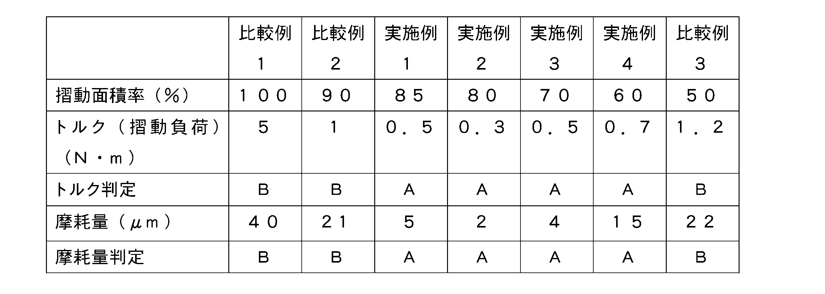
なお、図33および表1に示す実験においては、それぞれの樹脂製スラストワッシャ20Aについて、5時間摺動させた結果を示している。
In addition, in the experiment shown in FIG. 33 and Table 1, the results obtained by sliding the resin-made thrust washers 20A for 5 hours are shown.
かかる実験結果から、摺動面積率は、60%~85%の範囲内(すなわち、油溝面積率が15%~40%の範囲内)であれば、平均トルクが0.7N・m以下と小さくなることから、好ましいと言える。また、摺動面積率は、60%~85%の範囲内(すなわち、油溝面積率が15%~40%の範囲内)であれば、摩耗量が20μm以下と小さくなることから、好ましいと言える。
From such experimental results, if the sliding area ratio is in the range of 60% to 85% (that is, the oil groove area ratio is in the range of 15% to 40%), the average torque is 0.7 N·m or less. Since it becomes small, it can be said to be preferable. Further, if the sliding area ratio is in the range of 60% to 85% (that is, the oil groove area ratio is in the range of 15% to 40%), the wear amount is as small as 20 μm or less, which is preferable. I can say.
なお、比較例1,2においては、油溝面積率が低すぎて、潤滑油の潤滑性が悪化していると考えられる。
In Comparative Examples 1 and 2, it is considered that the oil groove area ratio is too low and the lubricity of the lubricating oil is deteriorated.
(3)第2構成例に係る樹脂製スラストワッシャ20Aの摺動面積率(油溝面積率)の実験結果について
次に、上記の負荷測定装置300に、図11および図12に示すような、第2構成例に係る樹脂製スラストワッシャ20Aを取り付けて行った、樹脂製スラストワッシャ20Aの摺動面積率とトルク(平均トルク)の関係に関する実験結果を、図34に示す。この実験では、底部251の幅に対応した寸法は0.80mm、油溝25の幅に対応した寸法は2.10mm、底部251から摺動面26までの高さは0.30mmとなっている。そして、この実験では、油溝25の本数および溝幅を変更することで、摺動面積率を変更して、実験を行っている。なお、実験条件は、図33および表1に示す実験結果と同一条件となっている。 (3) Regarding Experimental Results of Sliding Area Ratio (Oil Groove Area Ratio) of the Resin Thrust Washer 20A according to the Second Configuration Example Next, in theload measuring device 300 described above, as shown in FIG. 11 and FIG. FIG. 34 shows an experimental result regarding the relationship between the sliding area ratio of the resin thrust washer 20A and the torque (average torque), which was performed by attaching the resin thrust washer 20A according to the second configuration example. In this experiment, the dimension corresponding to the width of the bottom 251 is 0.80 mm, the dimension corresponding to the width of the oil groove 25 is 2.10 mm, and the height from the bottom 251 to the sliding surface 26 is 0.30 mm. .. In this experiment, the sliding area ratio is changed by changing the number of oil grooves 25 and the groove width, and the experiment is conducted. The experimental conditions are the same as the experimental results shown in FIG. 33 and Table 1.
次に、上記の負荷測定装置300に、図11および図12に示すような、第2構成例に係る樹脂製スラストワッシャ20Aを取り付けて行った、樹脂製スラストワッシャ20Aの摺動面積率とトルク(平均トルク)の関係に関する実験結果を、図34に示す。この実験では、底部251の幅に対応した寸法は0.80mm、油溝25の幅に対応した寸法は2.10mm、底部251から摺動面26までの高さは0.30mmとなっている。そして、この実験では、油溝25の本数および溝幅を変更することで、摺動面積率を変更して、実験を行っている。なお、実験条件は、図33および表1に示す実験結果と同一条件となっている。 (3) Regarding Experimental Results of Sliding Area Ratio (Oil Groove Area Ratio) of the Resin Thrust Washer 20A according to the Second Configuration Example Next, in the
なお、図34に示す各点のうち、摺動面積率が90%(油溝面積率が10%)の点が比較例11に対応し、摺動面積率が85%(油溝面積率が15%)の点が実施例11に対応し、摺動面積率が80%(油溝面積率が20%)の点が実施例12に対応し、摺動面積率が70%(油溝面積率が30%)の点が実施例13に対応し、摺動面積率が60%(油溝面積率が40%)の点が実施例14に対応し、摺動面積率が50%(油溝面積率が50%)の点が比較例12に対応している。
Of the points shown in FIG. 34, the point where the sliding area ratio is 90% (oil groove area ratio is 10%) corresponds to Comparative Example 11, and the sliding area ratio is 85% (oil groove area ratio is 15%) corresponds to Example 11, a sliding area ratio of 80% (oil groove area ratio 20%) corresponds to Example 12, and a sliding area ratio of 70% (oil groove area). The ratio of 30%) corresponds to Example 13, the sliding area ratio of 60% (oil groove area ratio of 40%) corresponds to Example 14, and the sliding area ratio of 50% (oil ratio). The groove area ratio is 50%) corresponds to Comparative Example 12.
また、図34の実験結果に対応する、トルク(摺動負荷)、摩耗量およびそれらの判定結果(トルク判定および摩耗量判定)を表2に示す。この表2のトルク判定では、トルク(摺動負荷)が0.2N・m以下の樹脂製スラストワッシャ20Aを、低摺動負荷の基準を満たすものとして「A」で示し、トルク(摺動負荷)が0.2N・mよりも大きな樹脂製スラストワッシャ20Aを、低摺動負荷の基準を満たさないものとして「B」で示している。また、表2の摩耗量判定では、摩耗量が30μm以下の樹脂製スラストワッシャ20Aを、低摩耗量の基準を満たすものとして「A」で示し、摩耗量が30μmよりも大きな樹脂製スラストワッシャ20Aを、低低摩耗量の基準を満たさないものとして「B」で示している。
Table 2 shows the torque (sliding load), the wear amount, and the determination results (torque determination and wear amount determination) corresponding to the experimental results of FIG. 34. In the torque determination in Table 2, the resin thrust washer 20A having a torque (sliding load) of 0.2 N·m or less is indicated by “A” as satisfying the criterion of the low sliding load, and the torque (sliding load) is shown. ) Is larger than 0.2 N·m, and the resin-made thrust washer 20A is indicated by “B” as not satisfying the standard of low sliding load. In addition, in the wear amount determination of Table 2, the resin-made thrust washer 20A having a wear amount of 30 μm or less is indicated by “A” as satisfying the criterion of the low wear amount, and the resin-made thrust washer 20A having a wear amount of greater than 30 μm is shown. Is indicated as "B" as not satisfying the criterion of low wear amount.

かかる実験結果から、摺動面積率は、60%~85%の範囲内(すなわち、油溝面積率が15%~40%の範囲内)であれば、平均トルクが0.2N・m以下と小さくなることから、好ましいと言える。また、実験した範囲内では、全ての範囲内で摩耗量が20μm以下と小さくなっている。これらの結果から、第2構成例に係る樹脂製スラストワッシャ20Aでは、摺動面積率が60%~85%の範囲内(すなわち、油溝面積率が15%~40%の範囲内)が、低摺動負荷および低摩耗量の両方の基準を満たすので、好ましいと言える。
From such experimental results, if the sliding area ratio is in the range of 60% to 85% (that is, the oil groove area ratio is in the range of 15% to 40%), the average torque is 0.2 N·m or less. Since it becomes small, it can be said to be preferable. Further, within the range of the experiment, the wear amount was as small as 20 μm or less in all the ranges. From these results, in the resin thrust washer 20A according to the second configuration example, the sliding area ratio is within the range of 60% to 85% (that is, the oil groove area ratio is within the range of 15% to 40%). It can be said to be preferable because it satisfies both the criteria of low sliding load and low wear amount.
なお、比較例11においては、潤滑油のせん断抵抗が大きくなっていることから、トルク(摺動負荷)が大きくなっていると考えられる。また、比較例12においては、油溝面積率が50%と大きいことから、接触面が少なく摺動面26の面圧が高くなることから、トルク(摺動負荷)が大きくなっていると考えられる。
Incidentally, in Comparative Example 11, it is considered that the torque (sliding load) is large because the shear resistance of the lubricating oil is large. Further, in Comparative Example 12, since the oil groove area ratio is as large as 50%, it is considered that the torque (sliding load) is large because the contact surface is small and the surface pressure of the sliding surface 26 is high. To be
(4)第4構成例に係る樹脂製スラストワッシャ20Bの摺動面積率(油溝面積率)の実験結果について
次に、上記の負荷測定装置300に、図17および図18に示すような、第4構成例に係る樹脂製スラストワッシャ20Bを取り付けて実験を行った。この実験では、樹脂製スラストワッシャ20Bの摺動面積率とトルク(平均トルク)の関係に関して実験結果が得られた。その実験結果を、図35に示す。この実験では、底部251の幅に対応した寸法は0.50mm、油溝25の幅に対応した寸法は1.50mm、底部251から摺動面26までの高さは0.25mmとなっている。そして、この実験では、油溝25の本数および溝幅を変更することで、摺動面積率を変更して、実験を行っている。なお、実験条件は、図18および表1に示す実験結果と同一条件となっている。 (4) Experimental Results of Sliding Area Ratio (Oil Groove Area Ratio) of the Resin Thrust Washer 20B according to the Fourth Configuration Example Next, in theload measuring device 300, as shown in FIGS. 17 and 18, An experiment was conducted with the resin-made thrust washer 20B according to the fourth configuration example being attached. In this experiment, experimental results were obtained regarding the relationship between the sliding area ratio of the resin thrust washer 20B and the torque (average torque). The experimental results are shown in FIG. In this experiment, the dimension corresponding to the width of the bottom 251 is 0.50 mm, the dimension corresponding to the width of the oil groove 25 is 1.50 mm, and the height from the bottom 251 to the sliding surface 26 is 0.25 mm. .. In this experiment, the sliding area ratio is changed by changing the number of oil grooves 25 and the groove width, and the experiment is conducted. The experimental conditions are the same as the experimental results shown in FIG. 18 and Table 1.
次に、上記の負荷測定装置300に、図17および図18に示すような、第4構成例に係る樹脂製スラストワッシャ20Bを取り付けて実験を行った。この実験では、樹脂製スラストワッシャ20Bの摺動面積率とトルク(平均トルク)の関係に関して実験結果が得られた。その実験結果を、図35に示す。この実験では、底部251の幅に対応した寸法は0.50mm、油溝25の幅に対応した寸法は1.50mm、底部251から摺動面26までの高さは0.25mmとなっている。そして、この実験では、油溝25の本数および溝幅を変更することで、摺動面積率を変更して、実験を行っている。なお、実験条件は、図18および表1に示す実験結果と同一条件となっている。 (4) Experimental Results of Sliding Area Ratio (Oil Groove Area Ratio) of the Resin Thrust Washer 20B according to the Fourth Configuration Example Next, in the
なお、図35に示す各点のうち、摺動面積率が90%(油溝面積率が10%)の点が比較例21に対応し、摺動面積率が85%(油溝面積率が15%)の点が実施例21に対応し、摺動面積率が80%(油溝面積率が20%)の点が実施例22に対応し、摺動面積率が70%(油溝面積率が30%)の点が実施例23に対応し、摺動面積率が60%(油溝面積率が40%)の点が実施例24に対応し、摺動面積率が50%(油溝面積率が50%)の点が比較例22に対応している。
35, the sliding area ratio of 90% (oil groove area ratio 10%) corresponds to Comparative Example 21, and the sliding area ratio of 85% (oil groove area ratio 15%) corresponds to Example 21, the sliding area ratio is 80% (oil groove area ratio is 20%), and the sliding area ratio is 70% (oil groove area). The ratio of 30%) corresponds to Example 23, the sliding area ratio of 60% (oil groove area ratio of 40%) corresponds to Example 24, and the sliding area ratio of 50% (oil ratio). The groove area ratio is 50%) corresponds to Comparative Example 22.
また、図35の実験結果に対応する、トルク(摺動負荷)、摩耗量およびそれらの判定結果(トルク判定および摩耗量判定)を表3に示す。この表3のトルク判定の判定基準は0.2N・m以下の場合が「A]、0.2N・mより大きい場合が「B」であり、また摩耗量判定の判定基準は30μm以下の場合が「A」、30μmより大きい場合が「B」であり、それぞれ表2の場合と同様となっている。
Further, Table 3 shows the torque (sliding load), the wear amount, and the determination results (torque determination and wear amount determination) corresponding to the experimental results of FIG. In Table 3, the judgment criterion for torque judgment is “A” when the torque is 0.2 N·m or less, “B” when the torque is larger than 0.2 N·m, and the criterion for the wear amount judgment is 30 μm or less. Is “A”, and “B” is larger than 30 μm, which is the same as in Table 2.
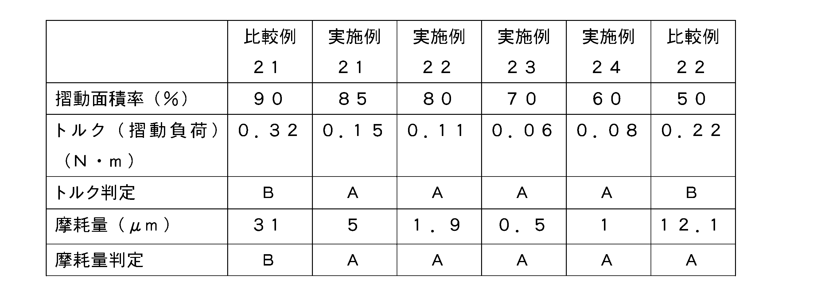
かかる実験結果から、摺動面積率は、60%~85%の範囲内(すなわち、油溝面積率が15%~40%の範囲内)であれば、平均トルクが0.2N・m以下と小さくなることから、好ましいと言える。また、摺動面積率は、50%~85%の範囲内(すなわち、油溝面積率が15%~50%の範囲内)であれば、摩耗量が30μm以下と小さくなることから、好ましいと言える。これらの結果から、第4構成例に係る樹脂製スラストワッシャ20Bでは、摺動面積率が60%~85%の範囲内(すなわち、油溝面積率が15%~40%の範囲内)が、低摺動負荷および低摩耗量の両方の基準を満たすので、好ましいと言える。
From such experimental results, if the sliding area ratio is in the range of 60% to 85% (that is, the oil groove area ratio is in the range of 15% to 40%), the average torque is 0.2 N·m or less. Since it becomes small, it can be said to be preferable. In addition, if the sliding area ratio is within the range of 50% to 85% (that is, the oil groove area ratio is within the range of 15% to 50%), the wear amount is reduced to 30 μm or less, which is preferable. I can say. From these results, in the resin thrust washer 20B according to the fourth configuration example, the sliding area ratio is within the range of 60% to 85% (that is, the oil groove area ratio is within the range of 15% to 40%). It can be said to be preferable because it satisfies both the criteria of low sliding load and low wear amount.
なお、比較例21においては、潤滑油のせん断抵抗が大きくなっていることから、トルク(摺動負荷)が大きくなっていると考えられる。また、比較例22においては、油溝面積率が50%と大きいことから、接触面が少なく摺動面26の面圧が高くなることから、トルク(摺動負荷)が大きくなっていると考えられる。
In Comparative Example 21, the torque (sliding load) is considered to be large because the shear resistance of the lubricating oil is large. Further, in Comparative Example 22, since the oil groove area ratio is as large as 50%, it is considered that the torque (sliding load) is large because the contact surface is small and the surface pressure of the sliding surface 26 is high. To be
(5)第2構成例に係る樹脂製スラストワッシャ20Aにおいて、摺動面積率が85%(油溝面積率が15%)の場合の溝角度に関する実験結果について
次に、図11および図12に示すような第2構成例に係ると共に摺動面積率が85%(油溝面積率が15%)である樹脂製スラストワッシャ20Aを、上述の負荷測定装置300に取り付けて実験を行った。その実験結果を表4に示す。表4では、溝角度を変更したときのトルク(摺動負荷)、摩耗量およびそれらの判定結果(トルク判定および摩耗量判定)が示されている。この表4においては、油溝25の溝角度が30度の場合が実施例31に対応し、油溝25の溝角度が40度の場合が実施例32に対応し、油溝25の溝角度が45度の場合が実施例33に対応し、油溝25の溝角度が50度の場合が実施例34に対応し、油溝25の溝角度が55度の場合が実施例35に対応し、油溝25の溝角度が60度の場合が実施例36に対応している。 (5) Experimental Results on Groove Angle when Sliding Area Ratio is 85% (Oil Groove Area Ratio is 15%) in the Resin Thrust Washer 20A according to the Second Configuration Example Next, FIG. 11 and FIG. An experiment was carried out by attaching the resin-made thrust washer 20A having a sliding area ratio of 85% (oil groove area ratio of 15%) to the above-describedload measuring device 300 according to the second configuration example as shown. The experimental results are shown in Table 4. Table 4 shows the torque (sliding load), the amount of wear and their determination results (torque determination and wear amount determination) when the groove angle is changed. In Table 4, the case where the groove angle of the oil groove 25 is 30 degrees corresponds to Example 31, the case where the groove angle of the oil groove 25 is 40 degrees corresponds to Example 32, and the groove angle of the oil groove 25 is Of 45 degrees corresponds to Example 33, the case where the groove angle of the oil groove 25 is 50 degrees corresponds to Example 34, and the case where the groove angle of the oil groove 25 is 55 degrees corresponds to Example 35. The case where the groove angle of the oil groove 25 is 60 degrees corresponds to Example 36.
次に、図11および図12に示すような第2構成例に係ると共に摺動面積率が85%(油溝面積率が15%)である樹脂製スラストワッシャ20Aを、上述の負荷測定装置300に取り付けて実験を行った。その実験結果を表4に示す。表4では、溝角度を変更したときのトルク(摺動負荷)、摩耗量およびそれらの判定結果(トルク判定および摩耗量判定)が示されている。この表4においては、油溝25の溝角度が30度の場合が実施例31に対応し、油溝25の溝角度が40度の場合が実施例32に対応し、油溝25の溝角度が45度の場合が実施例33に対応し、油溝25の溝角度が50度の場合が実施例34に対応し、油溝25の溝角度が55度の場合が実施例35に対応し、油溝25の溝角度が60度の場合が実施例36に対応している。 (5) Experimental Results on Groove Angle when Sliding Area Ratio is 85% (Oil Groove Area Ratio is 15%) in the Resin Thrust Washer 20A according to the Second Configuration Example Next, FIG. 11 and FIG. An experiment was carried out by attaching the resin-made thrust washer 20A having a sliding area ratio of 85% (oil groove area ratio of 15%) to the above-described
また、表4のトルク判定の判定基準は0.2N・m以下の場合が「A]、0.2N・mより大きい場合が「B」であり、また摩耗量判定の判定基準は30μm以下の場合が「A」、30μmより大きい場合が「B」であり、それぞれ表2の場合と同様となっている。
Further, in Table 4, the judgment criterion for torque judgment is “A” when it is 0.2 N·m or less, and “B” when it is larger than 0.2 N·m, and the judgment criterion for wear amount judgment is 30 μm or less. The case is “A”, and the case of larger than 30 μm is “B”, which are the same as those in Table 2.
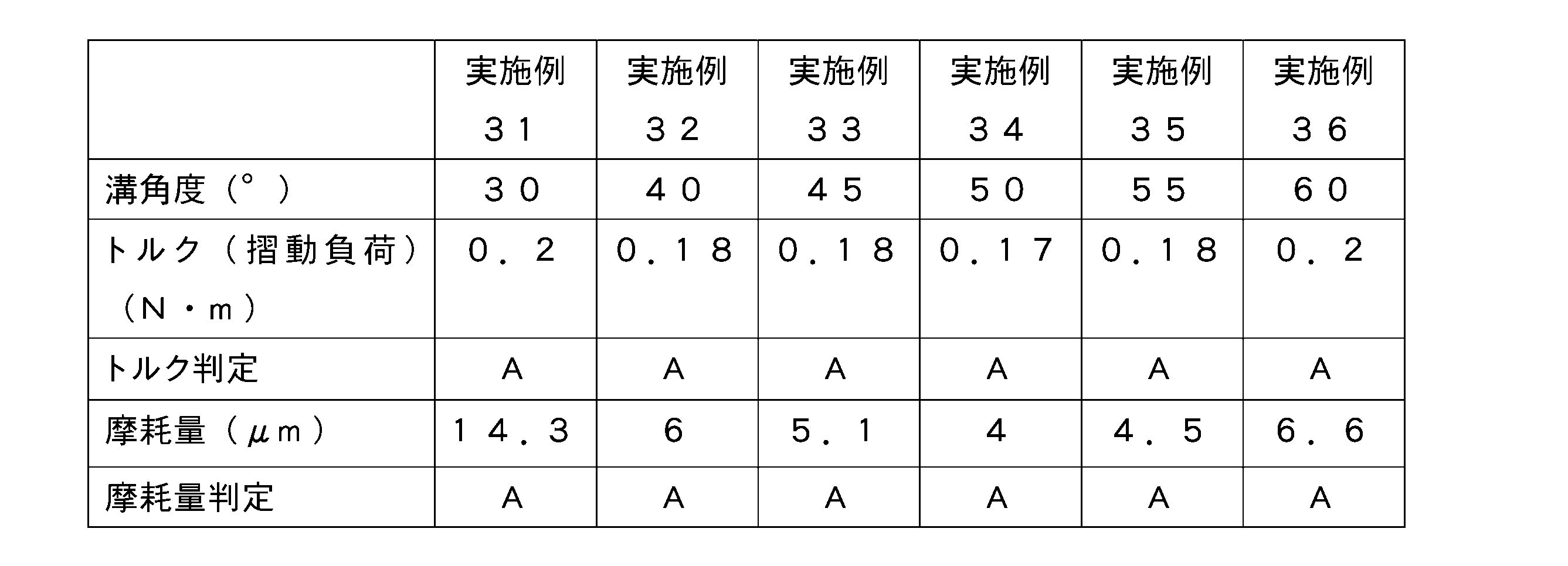
かかる実験結果から、摺動面積率が85%(すなわち、油溝面積率が15%)の場合、油溝25の溝角度が30度~60度の範囲内において、平均トルクが0.2N・m以下と小さくなると共に、摩耗量が30μm以下と小さくなることから、好ましいと言える。
From the experimental results, when the sliding area ratio is 85% (that is, the oil groove area ratio is 15%), when the groove angle of the oil groove 25 is in the range of 30 degrees to 60 degrees, the average torque is 0.2 N· It can be said that it is preferable because the wear amount is reduced to m or less and the wear amount is reduced to 30 μm or less.
(6)第2構成例に係る樹脂製スラストワッシャ20Aにおいて、摺動面積率が70%(油溝面積率が30%)の場合の溝角度に関する実験結果について
次に、図11および図12に示すような第2構成例に係ると共に摺動面積率が70%(油溝面積率が30%)である樹脂製スラストワッシャ20Aを、上述の負荷測定装置300に取り付けて実験を行った。その実験結果を表5に示す。表5では、溝角度を変更したときのトルク(摺動負荷)、摩耗量およびそれらの判定結果(トルク判定および摩耗量判定)が示されている。この表5においては、油溝25の溝角度が30度の場合が実施例41に対応し、油溝25の溝角度が40度の場合が実施例42に対応し、油溝25の溝角度が45度の場合が実施例43に対応し、油溝25の溝角度が50度の場合が実施例44に対応し、油溝25の溝角度が55度の場合が実施例45に対応し、油溝25の溝角度が60度の場合が実施例46に対応している。 (6) Experimental Results on Groove Angle when Sliding Area Ratio is 70% (Oil Groove Area Ratio is 30%) in the resin-made thrust washer 20A according to the second configuration example. Next, FIG. 11 and FIG. An experiment was conducted by attaching the resin-made thrust washer 20A having a sliding area ratio of 70% (oil groove area ratio of 30%) to the above-describedload measuring device 300 according to the second configuration example as shown. The experimental results are shown in Table 5. Table 5 shows the torque (sliding load) when the groove angle is changed, the amount of wear, and the determination results thereof (torque determination and wear amount determination). In Table 5, the oil groove 25 having a groove angle of 30 degrees corresponds to Example 41, the oil groove 25 having a groove angle of 40 degrees corresponds to Example 42, and the oil groove 25 has a groove angle of 40 degrees. Is 45 degrees, which corresponds to Example 43, the oil groove 25 having a groove angle of 50 degrees corresponds to Example 44, and the oil groove 25 having a groove angle of 55 degrees corresponds to Example 45. The case where the groove angle of the oil groove 25 is 60 degrees corresponds to Example 46.
次に、図11および図12に示すような第2構成例に係ると共に摺動面積率が70%(油溝面積率が30%)である樹脂製スラストワッシャ20Aを、上述の負荷測定装置300に取り付けて実験を行った。その実験結果を表5に示す。表5では、溝角度を変更したときのトルク(摺動負荷)、摩耗量およびそれらの判定結果(トルク判定および摩耗量判定)が示されている。この表5においては、油溝25の溝角度が30度の場合が実施例41に対応し、油溝25の溝角度が40度の場合が実施例42に対応し、油溝25の溝角度が45度の場合が実施例43に対応し、油溝25の溝角度が50度の場合が実施例44に対応し、油溝25の溝角度が55度の場合が実施例45に対応し、油溝25の溝角度が60度の場合が実施例46に対応している。 (6) Experimental Results on Groove Angle when Sliding Area Ratio is 70% (Oil Groove Area Ratio is 30%) in the resin-made thrust washer 20A according to the second configuration example. Next, FIG. 11 and FIG. An experiment was conducted by attaching the resin-made thrust washer 20A having a sliding area ratio of 70% (oil groove area ratio of 30%) to the above-described
また、表5のトルク判定の判定基準は0.2N・m以下の場合が「A]、0.2N・mより大きい場合が「B」であり、また摩耗量判定の判定基準は30μm以下の場合が「A」、30μmより大きい場合が「B」であり、それぞれ表2の場合と同様となっている。
Further, in Table 5, the judgment criterion for torque judgment is “A” when it is 0.2 N·m or less and “B” when it is larger than 0.2 N·m, and the judgment criterion for wear amount judgment is 30 μm or less. The case is “A”, and the case of larger than 30 μm is “B”, which are the same as those in Table 2.
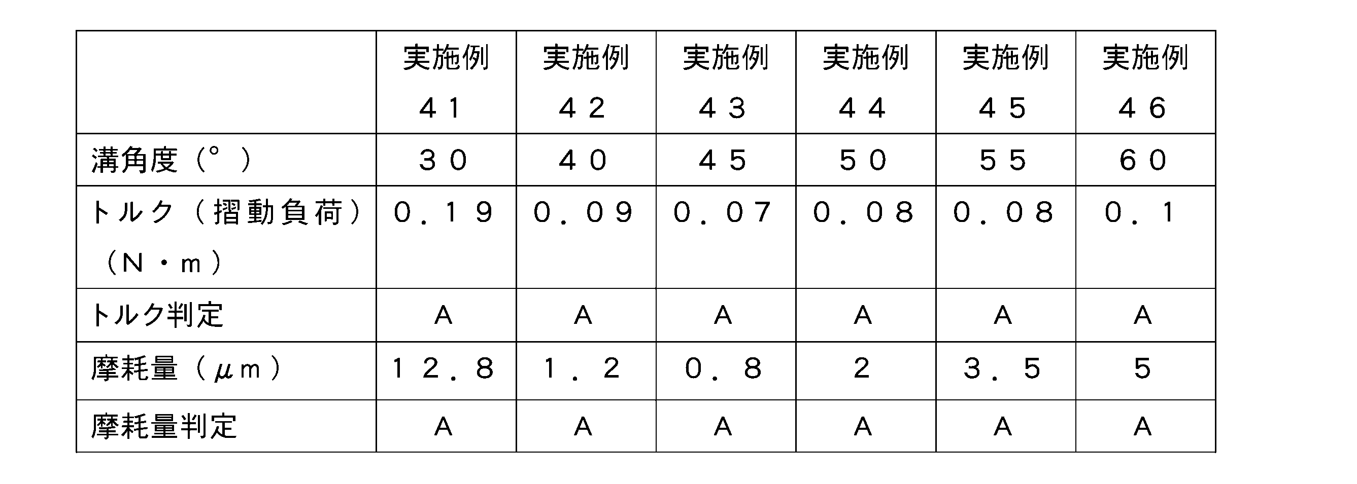
かかる実験結果から、摺動面積率が70%(すなわち、油溝面積率が30%)の場合、油溝25の溝角度が30度~60度の範囲内において、平均トルクが0.2N・m以下と小さくなると共に、摩耗量が30μm以下と小さくなることから、好ましいと言える。
From the experimental results, when the sliding area ratio is 70% (that is, the oil groove area ratio is 30%), when the groove angle of the oil groove 25 is in the range of 30 degrees to 60 degrees, the average torque is 0.2 N· It can be said that it is preferable because the wear amount is reduced to m or less and the wear amount is reduced to 30 μm or less.
(7)第2構成例に係る樹脂製スラストワッシャ20Aにおいて、摺動面積率が60%(油溝面積率が40%)の場合の溝角度に関する実験結果について
次に、図11および図12に示すような第2構成例に係ると共に摺動面積率が60%(油溝面積率が40%)である樹脂製スラストワッシャ20Aを、上述の負荷測定装置300に取り付けて実験を行った。その実験結果を表6に示す。表6では、溝角度を変更したときのトルク(摺動負荷)、摩耗量およびそれらの判定結果(トルク判定および摩耗量判定)が示されている。この表6においては、油溝25の溝角度が30度の場合が実施例51に対応し、油溝25の溝角度が40度の場合が実施例52に対応し、油溝25の溝角度が45度の場合が実施例53に対応し、油溝25の溝角度が50度の場合が実施例54に対応し、油溝25の溝角度が55度の場合が実施例55に対応し、油溝25の溝角度が60度の場合が実施例56に対応している。 (7) Experimental Results on Groove Angle when Sliding Area Ratio is 60% (Oil Groove Area Ratio is 40%) in the resin-made thrust washer 20A according to the second configuration example. Next, FIG. 11 and FIG. An experiment was carried out by attaching the resin-made thrust washer 20A having a sliding area ratio of 60% (oil groove area ratio of 40%) to the above-describedload measuring apparatus 300 according to the second configuration example as shown. The experimental results are shown in Table 6. Table 6 shows the torque (sliding load) when the groove angle is changed, the amount of wear and the determination results (torque determination and wear amount determination). In Table 6, the case where the groove angle of the oil groove 25 is 30 degrees corresponds to Example 51, the case where the groove angle of the oil groove 25 is 40 degrees corresponds to Example 52, and the groove angle of the oil groove 25 is shown. Of 45 degrees corresponds to Example 53, the groove angle of the oil groove 25 of 50 degrees corresponds to Example 54, and the groove angle of the oil groove 25 of 55 degrees corresponds to Example 55. The case where the groove angle of the oil groove 25 is 60 degrees corresponds to Example 56.
次に、図11および図12に示すような第2構成例に係ると共に摺動面積率が60%(油溝面積率が40%)である樹脂製スラストワッシャ20Aを、上述の負荷測定装置300に取り付けて実験を行った。その実験結果を表6に示す。表6では、溝角度を変更したときのトルク(摺動負荷)、摩耗量およびそれらの判定結果(トルク判定および摩耗量判定)が示されている。この表6においては、油溝25の溝角度が30度の場合が実施例51に対応し、油溝25の溝角度が40度の場合が実施例52に対応し、油溝25の溝角度が45度の場合が実施例53に対応し、油溝25の溝角度が50度の場合が実施例54に対応し、油溝25の溝角度が55度の場合が実施例55に対応し、油溝25の溝角度が60度の場合が実施例56に対応している。 (7) Experimental Results on Groove Angle when Sliding Area Ratio is 60% (Oil Groove Area Ratio is 40%) in the resin-made thrust washer 20A according to the second configuration example. Next, FIG. 11 and FIG. An experiment was carried out by attaching the resin-made thrust washer 20A having a sliding area ratio of 60% (oil groove area ratio of 40%) to the above-described
また、表6のトルク判定の判定基準は0.2N・m以下の場合が「A]、0.2N・mより大きい場合が「B」であり、また摩耗量判定の判定基準は30μm以下の場合が「A」、30μmより大きい場合が「B」であり、それぞれ表2の場合と同様となっている。
Further, in Table 6, the judgment criterion for torque judgment is “A” when the torque is 0.2 N·m or less and “B” when the torque is larger than 0.2 N·m, and the criterion for the wear amount judgment is 30 μm or less. The case is “A”, and the case of larger than 30 μm is “B”, which are the same as those in Table 2.

かかる実験結果から、摺動面積率が60%(すなわち、油溝面積率が40%)の場合、油溝25の溝角度が30度~60度の範囲内において、平均トルクが0.2N・m以下と小さくなると共に、摩耗量が30μm以下と小さくなることから、好ましいと言える。
From such experimental results, when the sliding area ratio is 60% (that is, the oil groove area ratio is 40%), when the groove angle of the oil groove 25 is in the range of 30 to 60 degrees, the average torque is 0.2 N· It can be said that it is preferable because the wear amount is reduced to m or less and the wear amount is reduced to 30 μm or less.
(8)第4構成例に係る樹脂製スラストワッシャ20Aにおいて、摺動面積率が85%(油溝面積率が15%)の場合の溝角度に関する実験結果について
次に、図17および図18に示すような第4構成例に係ると共に摺動面積率が85%(油溝面積率が15%)である樹脂製スラストワッシャ20Bを、上述の負荷測定装置300に取り付けて実験を行った。その実験結果を表7に示す。表7では、溝角度を変更したときのトルク(摺動負荷)、摩耗量およびそれらの判定結果(トルク判定および摩耗量判定)が示されている。この表7においては、油溝25の溝角度が30度の場合が実施例61に対応し、油溝25の溝角度が40度の場合が実施例62に対応し、油溝25の溝角度が45度の場合が実施例63に対応し、油溝25の溝角度が50度の場合が実施例64に対応し、油溝25の溝角度が55度の場合が実施例65に対応し、油溝25の溝角度が60度の場合が比較例61に対応している。 (8) Experimental Results on Groove Angle when Sliding Area Ratio is 85% (Oil Groove Area Ratio is 15%) in the resin thrust washer 20A according to the fourth configuration example. Next, FIG. 17 and FIG. An experiment was carried out by attaching the resin-made thrust washer 20B having a sliding area ratio of 85% (oil groove area ratio of 15%) to the aboveload measuring device 300 according to the fourth configuration example as shown. The experimental results are shown in Table 7. Table 7 shows the torque (sliding load) when the groove angle is changed, the amount of wear, and the determination results thereof (torque determination and wear amount determination). In Table 7, the oil groove 25 having a groove angle of 30 degrees corresponds to Example 61, the oil groove 25 having a groove angle of 40 degrees corresponds to Example 62, and the oil groove 25 has a groove angle of 40 degrees. Of 45 degrees corresponds to Example 63, the groove angle of the oil groove 25 of 50 degrees corresponds to Example 64, and the groove angle of the oil groove 25 of 55 degrees corresponds to Example 65. The case where the groove angle of the oil groove 25 is 60 degrees corresponds to Comparative Example 61.
次に、図17および図18に示すような第4構成例に係ると共に摺動面積率が85%(油溝面積率が15%)である樹脂製スラストワッシャ20Bを、上述の負荷測定装置300に取り付けて実験を行った。その実験結果を表7に示す。表7では、溝角度を変更したときのトルク(摺動負荷)、摩耗量およびそれらの判定結果(トルク判定および摩耗量判定)が示されている。この表7においては、油溝25の溝角度が30度の場合が実施例61に対応し、油溝25の溝角度が40度の場合が実施例62に対応し、油溝25の溝角度が45度の場合が実施例63に対応し、油溝25の溝角度が50度の場合が実施例64に対応し、油溝25の溝角度が55度の場合が実施例65に対応し、油溝25の溝角度が60度の場合が比較例61に対応している。 (8) Experimental Results on Groove Angle when Sliding Area Ratio is 85% (Oil Groove Area Ratio is 15%) in the resin thrust washer 20A according to the fourth configuration example. Next, FIG. 17 and FIG. An experiment was carried out by attaching the resin-made thrust washer 20B having a sliding area ratio of 85% (oil groove area ratio of 15%) to the above
また、表7のトルク判定の判定基準は0.2N・m以下の場合が「A]、0.2N・mより大きい場合が「B」、樹脂製スラストワッシャ20Aの製造ができない場合が「C」であり、また摩耗量判定の判定基準は30μm以下の場合が「A」、30μmより大きい場合が「B」、樹脂製スラストワッシャ20Aの製造ができない場合が「C」であり、それぞれ表2の場合と同様となっている。なお表7のトルク判定および摩耗量判定では、判定「B」はなく、判定「A」と判定「C」が存在する結果となっている。
Further, the judgment criteria of the torque judgment in Table 7 are “A” when the torque is 0.2 N·m or less, “B” when the torque is larger than 0.2 N·m, and “C” when the resin-made thrust washer 20A cannot be manufactured. “A” when the wear amount is 30 μm or less, “B” when the wear amount is larger than 30 μm, and “C” when the resin-made thrust washer 20A cannot be manufactured. It is similar to the case. In addition, in the torque determination and the wear amount determination in Table 7, there is no determination “B”, and the determination “A” and the determination “C” exist.
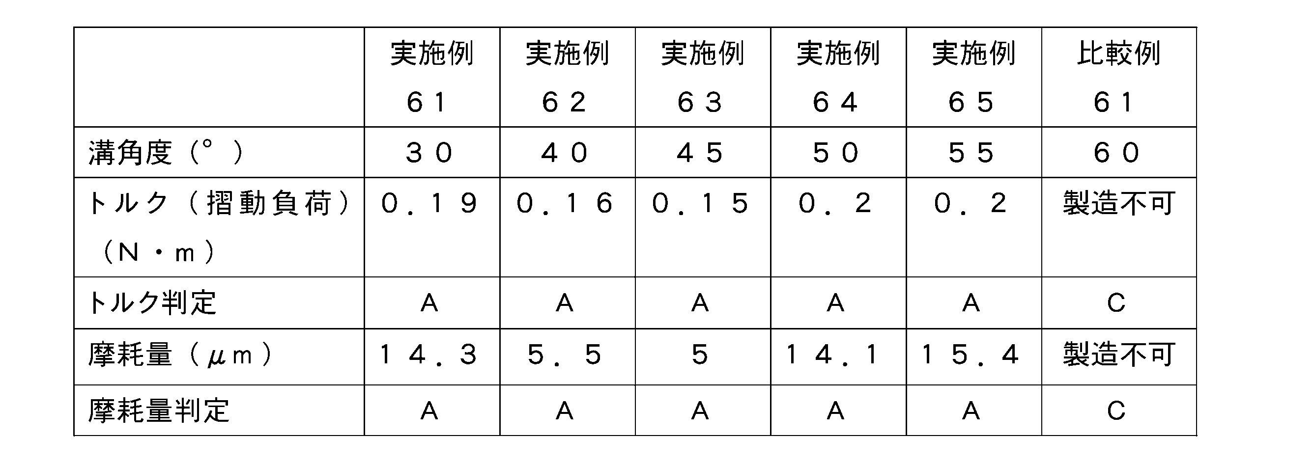
かかる実験結果では、略V字を描くように連結された油溝25を有する樹脂製スラストワッシャ20Bにおいて摺動面積率が85%(すなわち、油溝面積率が15%)の場合、比較例61のような溝角度が60度のときに、他の油溝25と干渉するので、製造不可となっている。しかしながら油溝25の溝角度が30度~55度の範囲内においてが、平均トルクが0.2N・m以下と小さくなると共に、摩耗量が30μm以下と小さくなることから、好ましいと言える。
According to the experimental result, in the resin thrust washer 20B having the oil grooves 25 connected so as to draw a substantially V shape, when the sliding area ratio is 85% (that is, the oil groove area ratio is 15%), Comparative Example 61 When the groove angle is 60 degrees as described above, it interferes with other oil grooves 25 and cannot be manufactured. However, when the groove angle of the oil groove 25 is in the range of 30 degrees to 55 degrees, the average torque is reduced to 0.2 N·m or less and the wear amount is reduced to 30 μm or less, which is preferable.
(9)第4構成例に係る樹脂製スラストワッシャ20Bにおいて、摺動面積率が70%(油溝面積率が30%)の場合の溝角度に関する実験結果について
次に、図17および図18に示すような第4構成例に係ると共に摺動面積率が70%(油溝面積率が30%)である樹脂製スラストワッシャ20Bを、上述の負荷測定装置300に取り付けて実験を行った。その実験結果を表8に示す。表8では、溝角度を変更したときのトルク(摺動負荷)、摩耗量およびそれらの判定結果(トルク判定および摩耗量判定)が示されている。この表8においては、油溝25の溝角度が30度の場合が実施例71に対応し、油溝25の溝角度が40度の場合が実施例72に対応し、油溝25の溝角度が45度の場合が実施例73に対応し、油溝25の溝角度が50度の場合が実施例74に対応し、油溝25の溝角度が55度の場合が実施例75に対応し、油溝25の溝角度が60度の場合が比較例71に対応している。 (9) Experimental Results on Groove Angle when Sliding Area Ratio is 70% (Oil Groove Area Ratio is 30%) in the resin thrust washer 20B according to the fourth configuration example. Next, FIG. 17 and FIG. An experiment was carried out by attaching the resin-made thrust washer 20B having a sliding area ratio of 70% (oil groove area ratio of 30%) to the above-describedload measuring device 300 according to the fourth configuration example as shown. The experimental results are shown in Table 8. Table 8 shows the torque (sliding load) when the groove angle is changed, the amount of wear and the determination results thereof (torque determination and wear amount determination). In Table 8, the case where the groove angle of the oil groove 25 is 30 degrees corresponds to Example 71, the case where the groove angle of the oil groove 25 is 40 degrees corresponds to Example 72, and the groove angle of the oil groove 25 is shown. Of 45 degrees corresponds to Example 73, the case where the groove angle of the oil groove 25 is 50 degrees corresponds to Example 74, and the case where the groove angle of the oil groove 25 is 55 degrees corresponds to Example 75. The case where the groove angle of the oil groove 25 is 60 degrees corresponds to Comparative Example 71.
次に、図17および図18に示すような第4構成例に係ると共に摺動面積率が70%(油溝面積率が30%)である樹脂製スラストワッシャ20Bを、上述の負荷測定装置300に取り付けて実験を行った。その実験結果を表8に示す。表8では、溝角度を変更したときのトルク(摺動負荷)、摩耗量およびそれらの判定結果(トルク判定および摩耗量判定)が示されている。この表8においては、油溝25の溝角度が30度の場合が実施例71に対応し、油溝25の溝角度が40度の場合が実施例72に対応し、油溝25の溝角度が45度の場合が実施例73に対応し、油溝25の溝角度が50度の場合が実施例74に対応し、油溝25の溝角度が55度の場合が実施例75に対応し、油溝25の溝角度が60度の場合が比較例71に対応している。 (9) Experimental Results on Groove Angle when Sliding Area Ratio is 70% (Oil Groove Area Ratio is 30%) in the resin thrust washer 20B according to the fourth configuration example. Next, FIG. 17 and FIG. An experiment was carried out by attaching the resin-made thrust washer 20B having a sliding area ratio of 70% (oil groove area ratio of 30%) to the above-described
また、表8のトルク判定の判定基準は0.2N・m以下の場合が「A]、0.2N・mより大きい場合が「B」、樹脂製スラストワッシャ20Bの製造ができない場合が「C」であり、また摩耗量判定の判定基準は30μm以下の場合が「A」、30μmより大きい場合が「B」、樹脂製スラストワッシャ20Bの製造ができない場合が「C」であり、それぞれ表2の場合と同様となっている。なお、表8のトルク判定および摩耗量判定では、判定「B」はなく、判定「A」と判定「C」が存在する結果となっている。
Further, the judgment criteria for torque judgment in Table 8 are “A” when the torque is 0.2 N·m or less, “B” when the torque is 0.2 N·m or more, and “C” when the resin thrust washer 20B cannot be manufactured. “A” when the wear amount is 30 μm or less, “B” when the wear amount is larger than 30 μm, and “C” when the resin thrust washer 20B cannot be manufactured. It is similar to the case. In addition, in the torque determination and the wear amount determination in Table 8, there is no determination “B”, and the determination “A” and the determination “C” exist.

かかる実験結果では、略V字を描くように連結された油溝25を有する樹脂製スラストワッシャ20Bにおいて摺動面積率が70%(すなわち、油溝面積率が30%)の場合、比較例71のような溝角度が60度のときに、他の油溝25と干渉するので、製造不可となっている。しかしながら油溝25の溝角度が30度~55度の範囲内においてが、平均トルクが0.2N・m以下と小さくなると共に、摩耗量が30μm以下と小さくなることから、好ましいと言える。
According to the experimental results, in the resin thrust washer 20B having the oil grooves 25 connected so as to draw a substantially V-shape, when the sliding area ratio is 70% (that is, the oil groove area ratio is 30%), Comparative Example 71 When such a groove angle is 60 degrees, it interferes with other oil grooves 25, and therefore cannot be manufactured. However, when the groove angle of the oil groove 25 is in the range of 30 degrees to 55 degrees, the average torque is reduced to 0.2 N·m or less and the wear amount is reduced to 30 μm or less, which is preferable.
(10)第4構成例に係る樹脂製スラストワッシャ20Bにおいて、摺動面積率が60%(油溝面積率が40%)の場合の溝角度に関する実験結果について
次に、図17および図18に示すような第4構成例に係ると共に摺動面積率が60%(油溝面積率が40%)である樹脂製スラストワッシャ20Bを、上述の負荷測定装置300に取り付けて実験を行った。その実験結果を表9に示す。表9では、溝角度を変更したときのトルク(摺動負荷)、摩耗量およびそれらの判定結果(トルク判定および摩耗量判定)が示されている。この表9においては、油溝25の溝角度が30度の場合が実施例81に対応し、油溝25の溝角度が40度の場合が実施例82に対応し、油溝25の溝角度が45度の場合が実施例83に対応し、油溝25の溝角度が50度の場合が実施例84に対応し、油溝25の溝角度が55度の場合が実施例85に対応し、油溝25の溝角度が60度の場合が比較例81に対応している。 (10) Experimental Results on Groove Angle when Sliding Area Ratio is 60% (Oil Groove Area Ratio is 40%) in the resin thrust washer 20B according to the fourth configuration example. Next, FIG. 17 and FIG. An experiment was conducted by attaching the resin-made thrust washer 20B having a sliding area ratio of 60% (oil groove area ratio of 40%) to the above-describedload measuring device 300 according to the fourth configuration example as shown. The experimental results are shown in Table 9. Table 9 shows the torque (sliding load) when the groove angle is changed, the amount of wear and the determination results (torque determination and wear amount determination). In Table 9, the case where the groove angle of the oil groove 25 is 30 degrees corresponds to Example 81, the case where the groove angle of the oil groove 25 is 40 degrees corresponds to Example 82, and the groove angle of the oil groove 25 is shown. Of 45 degrees corresponds to Example 83, the groove angle of the oil groove 25 of 50 degrees corresponds to Example 84, and the groove angle of the oil groove 25 of 55 degrees corresponds to Example 85. The case where the groove angle of the oil groove 25 is 60 degrees corresponds to Comparative Example 81.
次に、図17および図18に示すような第4構成例に係ると共に摺動面積率が60%(油溝面積率が40%)である樹脂製スラストワッシャ20Bを、上述の負荷測定装置300に取り付けて実験を行った。その実験結果を表9に示す。表9では、溝角度を変更したときのトルク(摺動負荷)、摩耗量およびそれらの判定結果(トルク判定および摩耗量判定)が示されている。この表9においては、油溝25の溝角度が30度の場合が実施例81に対応し、油溝25の溝角度が40度の場合が実施例82に対応し、油溝25の溝角度が45度の場合が実施例83に対応し、油溝25の溝角度が50度の場合が実施例84に対応し、油溝25の溝角度が55度の場合が実施例85に対応し、油溝25の溝角度が60度の場合が比較例81に対応している。 (10) Experimental Results on Groove Angle when Sliding Area Ratio is 60% (Oil Groove Area Ratio is 40%) in the resin thrust washer 20B according to the fourth configuration example. Next, FIG. 17 and FIG. An experiment was conducted by attaching the resin-made thrust washer 20B having a sliding area ratio of 60% (oil groove area ratio of 40%) to the above-described
また、表9のトルク判定の判定基準は0.2N・m以下の場合が「A]、0.2N・mより大きい場合が「B」、樹脂製スラストワッシャ20Bの製造ができない場合が「C」であり、また摩耗量判定の判定基準は30μm以下の場合が「A」、30μmより大きい場合が「B」、樹脂製スラストワッシャ20Bの製造ができない場合が「C」であり、それぞれ表2の場合と同様となっている。なお、表9のトルク判定および摩耗量判定では、判定「B」はなく、判定「A」と判定「C」が存在する結果となっている。
Further, the judgment criteria for torque judgment in Table 9 are "A" when the torque is 0.2 Nm or less, "B" when the torque is 0.2 Nm or more, and "C" when the resin thrust washer 20B cannot be manufactured. “A” when the wear amount is 30 μm or less, “B” when the wear amount is larger than 30 μm, and “C” when the resin thrust washer 20B cannot be manufactured. It is similar to the case. In addition, in the torque determination and the wear amount determination in Table 9, there is no determination “B”, and the determination “A” and the determination “C” exist.
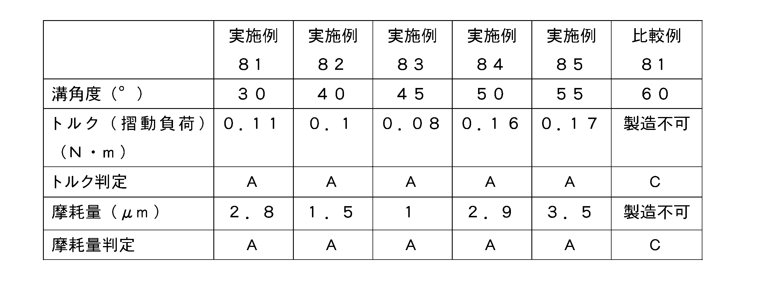
かかる実験結果では、略V字を描くように連結された油溝25を有する樹脂製スラストワッシャ20Bにおいて摺動面積率が60%(すなわち、油溝面積率が40%)の場合、比較例81のような溝角度が60度のときに、他の油溝25と干渉するので、製造不可となっている。しかしながら油溝25の溝角度が30度~55度の範囲内においてが、平均トルクが0.2N・m以下と小さくなると共に、摩耗量が30μm以下と小さくなることから、好ましいと言える。
According to the experimental results, in the resin thrust washer 20B having the oil grooves 25 connected so as to draw a substantially V shape, when the sliding area ratio is 60% (that is, the oil groove area ratio is 40%), Comparative Example 81 When such a groove angle is 60 degrees, it interferes with other oil grooves 25, and therefore cannot be manufactured. However, when the groove angle of the oil groove 25 is in the range of 30 degrees to 55 degrees, the average torque is reduced to 0.2 N·m or less and the wear amount is reduced to 30 μm or less, which is preferable.
(11)第3、第5~第11構成例に係る樹脂製スラストワッシャ20A,20Bにおいて、両面に油溝25を形成した場合の実験結果について
次に、第3、第5~第11構成例に係ると共に両面に油溝が形成されている樹脂製スラストワッシャ20A,20Bを、上述の、上述の負荷測定装置300に取り付けて実験を行った。なお、この実験では、摺動面積率が70%(油溝面積率が30%)であり溝角度が45度である樹脂製スラストワッシャ20A,20Bを用いて実験を行った。この実験結果を表10に示すが、その表10では、取り付ける樹脂製スラストワッシャ20A,20Bを変更したときのトルク(摺動負荷)、摩耗量およびそれらの判定結果(トルク判定および摩耗量判定)が示されている。 (11) Experimental Results in Case of FormingOil Grooves 25 on Both Sides of Resin Thrust Washers 20A, 20B According to Third, Fifth to Eleventh Configuration Examples Next, third, fifth to eleventh configuration examples The resin-made thrust washers 20A and 20B having the oil grooves formed on both sides of the above-mentioned are attached to the above-described load measuring device 300, and an experiment was conducted. In this experiment, the resin thrust washers 20A and 20B having a sliding area ratio of 70% (oil groove area ratio of 30%) and a groove angle of 45 degrees were used. The results of this experiment are shown in Table 10. In Table 10, the torque (sliding load) when the resin-made thrust washers 20A and 20B to be attached are changed, the amount of wear, and the determination results thereof (torque determination and wear amount determination). It is shown.
次に、第3、第5~第11構成例に係ると共に両面に油溝が形成されている樹脂製スラストワッシャ20A,20Bを、上述の、上述の負荷測定装置300に取り付けて実験を行った。なお、この実験では、摺動面積率が70%(油溝面積率が30%)であり溝角度が45度である樹脂製スラストワッシャ20A,20Bを用いて実験を行った。この実験結果を表10に示すが、その表10では、取り付ける樹脂製スラストワッシャ20A,20Bを変更したときのトルク(摺動負荷)、摩耗量およびそれらの判定結果(トルク判定および摩耗量判定)が示されている。 (11) Experimental Results in Case of Forming
この表10においては、第3構成例に係る樹脂製スラストワッシャ20Aの場合が実施例91に対応し、第5構成例に係る樹脂製スラストワッシャ20Aの場合が実施例92に対応し、第6構成例に係る樹脂製スラストワッシャ20Aの場合が実施例93に対応し、第7構成例に係る樹脂製スラストワッシャ20Aの場合が実施例94に対応し、第8構成例に係る樹脂製スラストワッシャ20Aの場合が実施例95に対応し、第9構成例に係る樹脂製スラストワッシャ20Aの場合が実施例96に対応し、第10構成例に係る樹脂製スラストワッシャ20Aの場合が実施例97に対応し、11構成例に係る樹脂製スラストワッシャ20Aの場合が実施例98に対応している。
In Table 10, the case of the resin-made thrust washer 20A according to the third configuration example corresponds to Example 91, the case of the resin-made thrust washer 20A according to the fifth configuration example corresponds to Example 92, and the sixth example The case of the resin-made thrust washer 20A according to the configuration example corresponds to Example 93, the case of the resin-made thrust washer 20A according to the seventh configuration example corresponds to Example 94, and the resin-made thrust washer according to the eighth configuration example. The case of 20A corresponds to Example 95, the case of the resin-made thrust washer 20A according to the ninth configuration example corresponds to Example 96, and the case of the resin-made thrust washer 20A according to the tenth configuration example corresponds to Example 97. Correspondingly, the case of the resin-made thrust washer 20A according to the eleventh configuration example corresponds to Example 98.
また、表10のトルク判定の判定基準は0.6N・m以下の場合が「A]、0.6N・mより大きい場合が「B」であり、また摩耗量判定の判定基準は30μm以下の場合が「A」、30μmより大きい場合が「B」である。
Further, in Table 10, the judgment criterion for torque judgment is “A” when 0.6 N·m or less and “B” when it is larger than 0.6 N·m, and the judgment criterion for wear amount judgment is 30 μm or less. The case is "A", and the case larger than 30 µm is "B".

かかる実験結果では、第3、第5~第11構成例に係る樹脂製スラストワッシャ20A,20Bであって、両面に油溝25が存在するいずれの樹脂製スラストワッシャ20A,20Bにおいても、平均トルクが0.6N・m以下と小さくなると共に、摩耗量が30μm以下と小さくなることから、好ましいと言える。
According to the results of the experiment, the average torque of the resin-made thrust washers 20A, 20B according to the third and fifth to eleventh configuration examples, and the resin-made thrust washers 20A, 20B having the oil grooves 25 on both surfaces thereof is shown. Is 0.6 N·m or less and the wear amount is 30 μm or less, which is preferable.
[6.作用効果]
以上のような構成の樹脂製スラストワッシャ20には、リング状部21の表面と裏面に他の部材(相手材C1,C2や他のスラストワッシャ)と摺動する摺動面26が設けられ、さらに表面と裏面の少なくとも一方に摺動面26から凹むと共に潤滑油が入り込む油溝25が設けられている。油溝25には、摺動面26よりも凹んでいると共に挿通孔22側から潤滑油が入り込むことを可能とする開口部27がリング状部21の内周端部に存在していて、少なくとも1つの油溝25のリング状部21の外周端部には、油溝25とリング状部21の外側とを隔てると共に油溝25に入り込んだ潤滑油がリング状部21の外周側に流出するのを抑制する油止壁28が設けられている。この油止壁28の樹脂製スラストワッシャ20の厚み方向における位置は摺動面26と同程度の位置に設けられていて、油溝面積率は、15%~40%の範囲内に設けられている。 [6. Action effect]
The resin thrust washer 20 having the above-described configuration is provided with the slidingsurfaces 26 on the front surface and the back surface of the ring-shaped portion 21 that slide with other members (the mating members C1 and C2 and other thrust washers). Further, an oil groove 25, which is recessed from the sliding surface 26 and into which lubricating oil enters, is provided on at least one of the front surface and the back surface. An opening 27, which is recessed from the sliding surface 26 and allows the lubricating oil to enter from the insertion hole 22 side, exists in the oil groove 25 at the inner peripheral end portion of the ring-shaped portion 21, and at least At the outer peripheral end of the ring-shaped portion 21 of one oil groove 25, the lubricating oil that separates the oil groove 25 and the outside of the ring-shaped portion 21 and that has entered the oil groove 25 flows out to the outer peripheral side of the ring-shaped portion 21. An oil stop wall 28 that suppresses the oil is provided. The position of the oil stop wall 28 in the thickness direction of the resin thrust washer 20 is provided at the same position as the sliding surface 26, and the oil groove area ratio is provided within the range of 15% to 40%. There is.
以上のような構成の樹脂製スラストワッシャ20には、リング状部21の表面と裏面に他の部材(相手材C1,C2や他のスラストワッシャ)と摺動する摺動面26が設けられ、さらに表面と裏面の少なくとも一方に摺動面26から凹むと共に潤滑油が入り込む油溝25が設けられている。油溝25には、摺動面26よりも凹んでいると共に挿通孔22側から潤滑油が入り込むことを可能とする開口部27がリング状部21の内周端部に存在していて、少なくとも1つの油溝25のリング状部21の外周端部には、油溝25とリング状部21の外側とを隔てると共に油溝25に入り込んだ潤滑油がリング状部21の外周側に流出するのを抑制する油止壁28が設けられている。この油止壁28の樹脂製スラストワッシャ20の厚み方向における位置は摺動面26と同程度の位置に設けられていて、油溝面積率は、15%~40%の範囲内に設けられている。 [6. Action effect]
The resin thrust washer 20 having the above-described configuration is provided with the sliding
このため、油溝25に入り込んだ潤滑油は、油止壁28によって樹脂性スラストワッシャ20の外周側に流出するのが抑制される。したがって、樹脂性スラストワッシャ20のうち油溝25が存在する面側では、他の部材(相手材C1,C2や他のスラストワッシャ)との間に、潤滑油による油膜を容易に形成することが可能となる。また、油溝面積率が15%~40%の範囲内に設けられている。このため、表32~表34および表1~表10の実験結果から明らかなように、樹脂性スラストワッシャ20のうち油溝25が存在する面側と他の部材(相手材C1,C2や他のスラストワッシャ)との間では、摺動負荷を低減することが可能となる。
Therefore, the lubricating oil that has entered the oil groove 25 is suppressed by the oil stop wall 28 from flowing out to the outer peripheral side of the resinous thrust washer 20. Therefore, on the surface side of the resinous thrust washer 20 where the oil groove 25 is present, an oil film of lubricating oil can be easily formed between the resinous thrust washer 20 and the other members (the mating members C1, C2 and other thrust washers). It will be possible. Further, the oil groove area ratio is provided within a range of 15% to 40%. Therefore, as is clear from the experimental results of Tables 32 to 34 and Tables 1 to 10, the surface side of the resinous thrust washer 20 on which the oil groove 25 is present and other members (the mating members C1, C2 and other members). It is possible to reduce the sliding load between the thrust washer and the thrust washer.
また、本実施の形態では、油溝25の中心線L2とリング状部21の径方向における中央線L1とが交差する交差位置において、その交差位置を通ると共に径方向に沿う径方向線L3に対して油溝25の中心線L2がなす傾斜角度θ1は、30度から55度の範囲内に設けられていることが好ましい。
Further, in the present embodiment, at the intersecting position where the center line L2 of the oil groove 25 and the radial center line L1 of the ring-shaped portion 21 intersect, a radial line L3 that passes through the intersecting position and extends in the radial direction is formed. On the other hand, the inclination angle θ1 formed by the center line L2 of the oil groove 25 is preferably provided within the range of 30 degrees to 55 degrees.
このように構成する場合には、表1から表10に示される実験結果から明らかなように、樹脂製スラストワッシャ20Aの摩耗量および平均トルク(摺動負荷)を一層低減することが可能となる。
With such a configuration, as is clear from the experimental results shown in Tables 1 to 10, it is possible to further reduce the wear amount and average torque (sliding load) of the resin thrust washer 20A. ..
また、本実施の形態では、油溝25には、当該油溝25に入り込んだ潤滑油を摺動面26にガイドさせて該摺動面26と他の部材(相手材C1,C2や他のスラストワッシャ)との間に動圧を生じさせるための動圧用ガイド壁面254が隣接して設けられていることが好ましい。
Further, in the present embodiment, the oil groove 25 guides the lubricating oil that has entered the oil groove 25 to the sliding surface 26 and the sliding surface 26 and other members (the mating members C1, C2 and other members). It is preferable that a dynamic pressure guide wall surface 254 for generating dynamic pressure is provided adjacent to the thrust washer).
このように、図15および図16に示すような動圧用ガイド壁面254を油溝25に隣接させて設ける場合には、樹脂製スラストワッシャ20Aの平均トルク(摺動負荷)を一層低減することが可能となる。
Thus, when the dynamic pressure guide wall surface 254 as shown in FIGS. 15 and 16 is provided adjacent to the oil groove 25, the average torque (sliding load) of the resin thrust washer 20A can be further reduced. It will be possible.
また、本実施の形態では、油溝25には、リング状部21の径方向に対して一方側に傾斜している第1油溝25cと、リング状部21の径方向に対して一方側とは異なる他方側に傾斜している第2油溝25dとが設けられていて、第1油溝25cと第2油溝25dは、開口部27で連結されていることが好ましい。
Further, in the present embodiment, the oil groove 25 includes a first oil groove 25c inclined to one side with respect to the radial direction of the ring-shaped portion 21 and one side with respect to the radial direction of the ring-shaped portion 21. It is preferable that a second oil groove 25d that is inclined to the other side different from is provided, and that the first oil groove 25c and the second oil groove 25d be connected by the opening 27.
このように構成する場合には、第1油溝25cと第2油溝25dとは、径方向を挟んで、一方側と他方側にそれぞれ傾斜している。したがって、樹脂性スラストワッシャ20Bのうち油溝25が存在する面側では、樹脂性スラストワッシャ20Bが時計回りおよび反時計回りのいずれに回転しても、他の部材(相手材C1,C2や他のスラストワッシャ)との間に、潤滑油による油膜を容易に形成することが可能となる。そのため、樹脂性スラストワッシャ20Bのうち油溝25が存在する面側と他の部材(相手材C1,C2や他のスラストワッシャ)との間では、樹脂性スラストワッシャ20Bの回転方向を問わずに摺動負荷を低減することが可能となる。
In such a configuration, the first oil groove 25c and the second oil groove 25d are respectively inclined on one side and the other side with the radial direction sandwiched therebetween. Therefore, on the surface side of the resin thrust washer 20B where the oil groove 25 exists, even if the resin thrust washer 20B rotates in either the clockwise direction or the counterclockwise direction, other members (the mating members C1, C2 and other members) It is possible to easily form an oil film of lubricating oil between the above and the thrust washer. Therefore, between the surface side of the resinous thrust washer 20B where the oil groove 25 is present and other members (the mating members C1, C2 and other thrust washers), the resinous thrust washer 20B does not matter in the rotating direction. It is possible to reduce the sliding load.
また、本実施の形態では、第1油溝25cおよび第2油溝25dには、摺動面26から最も凹んだ底部251がそれぞれ設けられていて、第1油溝25cおよび第2油溝25dには、第1油溝25cおよび第2油溝25dで囲まれない外側に位置する部位に、摺動面26に向かって直線状に傾斜するテーパ壁面252が設けられていて、テーパ壁面252は、底部251よりも幅広に設けられていることが好ましい。
Further, in the present embodiment, the first oil groove 25c and the second oil groove 25d are respectively provided with the bottom portions 251 that are the most recessed from the sliding surface 26, and the first oil groove 25c and the second oil groove 25d are provided. Is provided with a taper wall surface 252 that is linearly inclined toward the sliding surface 26 at a portion located outside and not surrounded by the first oil groove 25c and the second oil groove 25d. It is preferable that it is provided wider than the bottom portion 251.
このように構成する場合には、幅広のテーパ壁面252により、油溝25に入り込んだ潤滑油が摺動面26にガイドされるので、樹脂性スラストワッシャ20と他の部材(相手材C1,C2や他のスラストワッシャ)との間の摺動負荷を一層低減することが可能となる。
In such a configuration, the wide tapered wall surface 252 guides the lubricating oil that has entered the oil groove 25 to the sliding surface 26, so that the resinous thrust washer 20 and other members (the mating members C1 and C2) are guided. It is possible to further reduce the sliding load between the and other thrust washers).
また、本実施の形態では、第1油溝25cおよび第2油溝25dには、底部251から摺動面26に向かうと共に変曲点が存在するように湾曲している湾曲壁面255が設けられていることが好ましい。
In addition, in the present embodiment, the first oil groove 25c and the second oil groove 25d are provided with curved wall surfaces 255 that are curved so that there is an inflection point from the bottom portion 251 toward the sliding surface 26. Preferably.
このように構成する場合には、湾曲壁面255により、油溝25に入り込んだ潤滑油が摺動面26にガイドされるので、樹脂性スラストワッシャ20と他の部材(相手材C1,C2や他のスラストワッシャ)との間の摺動負荷を一層低減することが可能となる。
In such a configuration, the curved wall surface 255 guides the lubricating oil that has entered the oil groove 25 to the sliding surface 26, so that the resinous thrust washer 20 and other members (the mating members C1, C2 and other members) are guided. It is possible to further reduce the sliding load between the thrust washer and the thrust washer.
[6.変形例]
以上、本発明の各実施の形態について説明したが、本発明はこれ以外にも種々変形可能となっている。以下、それについて述べる。 [6. Modification]
Although the respective embodiments of the present invention have been described above, the present invention can be variously modified other than this. This will be described below.
以上、本発明の各実施の形態について説明したが、本発明はこれ以外にも種々変形可能となっている。以下、それについて述べる。 [6. Modification]
Although the respective embodiments of the present invention have been described above, the present invention can be variously modified other than this. This will be described below.
上述の実施の形態では、1枚の樹脂製スラストワッシャ20の表面と裏面では、同じ形状の油溝25が設けられている。しかしながら、1枚の樹脂製スラストワッシャ20の表面と裏面に形成する油溝25が異なる形状であっても良い。また、組合せスラストワッシャ10を構成する樹脂製スラストワッシャ20に形成される油溝25の少なくとも1つが、他とは異なる形状であっても良い。たとえば、樹脂製スラストワッシャ20、金属製スラストワッシャや相手材C1,C2といった、油溝25が存在する摺動面26と対向する面の表面粗さに応じて、適切な量の潤滑油が供給されるように、油溝25の形状を変更するようにしても良い。
In the above-mentioned embodiment, the oil groove 25 having the same shape is provided on the front surface and the back surface of one resin thrust washer 20. However, the oil grooves 25 formed on the front surface and the back surface of one resin thrust washer 20 may have different shapes. Further, at least one of the oil grooves 25 formed in the resin-made thrust washer 20 constituting the combined thrust washer 10 may have a shape different from the other shapes. For example, an appropriate amount of lubricating oil is supplied according to the surface roughness of the surface of the resin-made thrust washer 20, the metal-made thrust washer, or the mating members C1 and C2 that faces the sliding surface 26 where the oil groove 25 exists. As described above, the shape of the oil groove 25 may be changed.
また、上述の実施の形態の各構成例の油溝25の寸法の具体的な値については、その一例を示している。しかしながら、油溝25は、その他の寸法値を採用しても良い。
Moreover, an example is shown about the concrete value of the dimension of the oil groove 25 of each structural example of the above-mentioned embodiment. However, the oil groove 25 may adopt other dimension values.
また、上述の各実施の形態における油溝25においては、径方向に沿う油溝25と、径方向に対して所定の傾斜角度で傾斜している油溝25とが混在していても良い。そのような構成例を、図36および図37に示す。図36に示す樹脂性スラストワッシャ20B(第12構成例)は、図25および図26に示すような第8構成例に係る樹脂性スラストワッシャ20Bと同様に、凸曲面部256、幅広溝部257および幅狭溝部258を有している。また、1セットの第1油溝25cと第2油溝25dの間の部位には、連通油溝25bが設けられている。いわば、互いに離間している(開口部27で接続されていない)第1油溝25cと第2油溝25dの間の部位には、図36に示すような連通油溝25b(中間連通油溝に対応)が設けられている。
Further, in the oil groove 25 in each of the above-described embodiments, the oil groove 25 along the radial direction and the oil groove 25 inclined at a predetermined inclination angle with respect to the radial direction may be mixed. An example of such a configuration is shown in FIGS. 36 and 37. The resin thrust washer 20B (twelfth configuration example) shown in FIG. 36 is similar to the resin thrust washer 20B according to the eighth configuration example shown in FIGS. 25 and 26, and has a convex curved surface portion 256, a wide groove portion 257, and It has a narrow groove portion 258. Further, a communication oil groove 25b is provided in a portion between the set of the first oil groove 25c and the second oil groove 25d. In other words, in a portion between the first oil groove 25c and the second oil groove 25d which are separated from each other (not connected by the opening 27), a communication oil groove 25b (intermediate communication oil groove) as shown in FIG. 36 is provided. Is provided).
このような構成とする場合には、非連通油溝25a以外に、油止壁28が存在せずにリング状部21の外側と連通している連通油溝25bとが設けられているので、連通油溝25bを介して潤滑油が内径側から外径側へと流通する。したがって、樹脂製スラストワッシャ20の摺動により生じた発熱は、潤滑油を介して外部に逃がすことが可能となる。そのため、樹脂製スラストワッシャ20の放熱性を良好にすることが可能となり、樹脂製スラストワッシャ20での熱蓄積により該樹脂製スラストワッシャ20が溶融してしまうのを防止可能となる。
In the case of such a configuration, in addition to the non-communication oil groove 25a, since the oil stop wall 28 does not exist and the communication oil groove 25b communicating with the outside of the ring-shaped portion 21 is provided, Lubricating oil flows from the inner diameter side to the outer diameter side through the communication oil groove 25b. Therefore, the heat generated by the sliding of the resin thrust washer 20 can be released to the outside through the lubricating oil. Therefore, it is possible to improve the heat dissipation of the resin-made thrust washer 20, and it is possible to prevent the resin-made thrust washer 20 from melting due to heat accumulation in the resin-made thrust washer 20.
また、連通油溝25bは、第1油溝25cと第2油溝25dに干渉しない状態でリング状部21の周方向において隣り合う開口部27の間に配置されている。したがって、摺動負荷の低減を図る非連通油溝25a(第1油溝25cおよび第2油溝25d)と、熱を外部に逃がすための連通油溝25bとをバランス良く摺動面26に配置する構成が実現できる。
The communication oil groove 25b is arranged between the openings 27 adjacent to each other in the circumferential direction of the ring-shaped portion 21 without interfering with the first oil groove 25c and the second oil groove 25d. Therefore, the non-communication oil groove 25a (the first oil groove 25c and the second oil groove 25d) for reducing the sliding load and the communication oil groove 25b for radiating heat to the outside are arranged on the sliding surface 26 in good balance. It is possible to realize the configuration.
また、非連通油溝25aには、幅広溝部257と、幅広溝部257よりも溝幅の狭い幅狭溝部258とが設けられていて、幅狭溝部258は開口部27に接続されている。また、幅広溝部257は、幅広溝部257と連続していると共に油止壁28側に設けられている。このため、摺動負荷を良好に低減することが可能となる。
Further, the non-communication oil groove 25a is provided with a wide groove portion 257 and a narrow groove portion 258 having a groove width narrower than that of the wide groove portion 257, and the narrow groove portion 258 is connected to the opening 27. The wide groove portion 257 is continuous with the wide groove portion 257 and is provided on the oil stop wall 28 side. Therefore, the sliding load can be favorably reduced.
また、互いに離間している非連通油溝25a(第1油溝25cと第2油溝25d)の間には、油止壁28が存在せずにリング状部21の外側と連通している連通油溝25b(中間連通油溝)が設けられている。このため、摺動負荷の低減を図る非連通油溝25a(第1油溝25cおよび第2油溝25d)と、熱を外部に逃がすための連通油溝25bとをバランス良く摺動面26に配置する構成が実現できる。
Further, the oil stop wall 28 does not exist between the non-communication oil grooves 25a (the first oil groove 25c and the second oil groove 25d) that are separated from each other, and communicates with the outside of the ring-shaped portion 21. A communication oil groove 25b (intermediate communication oil groove) is provided. Therefore, the non-communication oil groove 25a (the first oil groove 25c and the second oil groove 25d) for reducing the sliding load and the communication oil groove 25b for releasing the heat to the outside are formed on the sliding surface 26 in good balance. The arrangement can be realized.
また、図37に示す樹脂製スラストワッシャ20A(第13構成例)は、図27および図28に示すような第9構成例に係る樹脂性スラストワッシャ20Aと同様に、摺動用突起112、連通油溝113、動圧用ガイド壁面254を有している。また、周方向で隣り合う非連通油溝25aの間には、連通油溝25bが設けられている。
Further, the resin thrust washer 20A (thirteenth configuration example) shown in FIG. 37 is similar to the resin thrust washer 20A according to the ninth configuration example shown in FIGS. 27 and 28, and the sliding projection 112, the communicating oil. The groove 113 and the dynamic pressure guide wall surface 254 are provided. A communication oil groove 25b is provided between the non-communication oil grooves 25a that are adjacent to each other in the circumferential direction.
このような構成とする場合には、非連通油溝25aと連通油溝25bとは、リング状部21の周方向において交互に設けられている。そのため、摺動負荷の低減と、良好な放熱性の両方を実現することができる。
In the case of such a configuration, the non-communication oil grooves 25a and the communication oil grooves 25b are alternately provided in the circumferential direction of the ring-shaped portion 21. Therefore, both reduction of sliding load and good heat dissipation can be realized.
また、連通油溝25bには、非連通油溝25aに隣接して設けられている連通油溝113(隣接連通油溝)と、互いに離間している非連通油溝25aの間に存在する連通油溝25b(中間連通油溝)とが設けられている。このため、樹脂製スラストワッシャ20Aの放熱性を一層良好にすることが可能となる。
Further, in the communication oil groove 25b, there is communication between the communication oil groove 113 (adjacent communication oil groove) provided adjacent to the non-communication oil groove 25a and the non-communication oil groove 25a separated from each other. An oil groove 25b (intermediate communication oil groove) is provided. Therefore, the heat dissipation of the resin-made thrust washer 20A can be further improved.
なお、図36においては、連通油溝25bは、第1油溝25cと第2油溝25dに干渉しない状態でリング状部21の周方向において隣り合う開口部27の間に、1本配置されている。しかしながら、周方向で隣り合う開口部27の間に、2本以上の連通油溝25bが配置されても良い。また、周方向において隣り合う開口部27の間のうち、1箇所以上で、連通油溝25bが存在しなくても良い。また、連通油溝25bの配置は、周方向において規則的な配置としても良いが、不規則な配置としても良い。また、図36と図37に示す構成の少なくとも一方の構成においては、動圧用ガイド壁面254を備えない構成としても良い。
In addition, in FIG. 36, one communication oil groove 25b is arranged between the openings 27 that are adjacent to each other in the circumferential direction of the ring-shaped portion 21 without interfering with the first oil groove 25c and the second oil groove 25d. ing. However, two or more communicating oil grooves 25b may be arranged between the openings 27 adjacent to each other in the circumferential direction. Further, the communication oil groove 25b may not exist at one or more positions between the openings 27 that are adjacent to each other in the circumferential direction. The communication oil grooves 25b may be arranged regularly in the circumferential direction, but may be arranged irregularly. Further, in at least one of the configurations shown in FIGS. 36 and 37, the dynamic pressure guide wall surface 254 may not be provided.
なお、本発明は、上述した実施例や寸法例はあくまでも一例であり、上述した摺動面積率(油溝面積率)の範囲内であれば、上述した実施例や寸法例以外の場合にも、本発明に含まれ得ることは勿論である。
It should be noted that the present invention is merely an example of the above-described embodiments and dimensional examples, and may be applied to cases other than the above-mentioned embodiments and dimensional examples as long as they are within the above-mentioned sliding area ratio (oil groove area ratio). Of course, it can be included in the present invention.
10…組合せスラストワッシャ、20,20A,20B…樹脂製スラストワッシャ、21…リング状部、22…挿通孔、23…油導入溝、24…油掬い面、25…油溝、25a…非連通油溝、25b…連通油溝、25c…第1油溝、25d…第2油溝、26…摺動面、27…開口部、28,110a…油止壁、109…油堤部、110…分岐油溝、111…包囲部、112…摺動用突起、113…連通油溝(隣接連通油溝に対応)、114…油溜まり溝、114a…第1油溜まり溝、114b…第2油溜まり溝、115…底部、116…テーパ壁面、251…底部、252…テーパ壁面、253…凸曲面部、254…動圧用ガイド壁面、255…湾曲壁面、256…凸曲面部、257…幅広溝部、258…幅狭溝部、259…凹曲面部、260…凹曲面部、261…傾斜壁部、300…負荷測定装置、301…オイルパン、301a…内筒部、301b…油排出口、302…固定軸、303…回転軸、304…油供給路、305…熱電対、306,307…オイルシール、S1~S3…スラストワッシャ
10... Combination thrust washer, 20, 20A, 20B... Resin thrust washer, 21... Ring-shaped part, 22... Insertion hole, 23... Oil introduction groove, 24... Oil scooping surface, 25... Oil groove, 25a... Non-communication oil Groove, 25b... Communication oil groove, 25c... First oil groove, 25d... Second oil groove, 26... Sliding surface, 27... Opening portion, 28, 110a... Oil stop wall, 109... Oil bank portion, 110... Branch Oil groove, 111... Enclosing portion, 112... Sliding projection, 113... Communication oil groove (corresponding to adjacent communication oil groove), 114... Oil sump groove, 114a... First oil sump groove, 114b... Second oil sump groove, 115... Bottom part, 116... Tapered wall surface, 251... Bottom part, 252... Tapered wall surface, 253... Convex curved surface part, 254... Dynamic pressure guide wall surface, 255... Curved wall surface, 256... Convex curved surface part, 257... Wide groove part, 258... Width Narrow groove portion, 259... Recessed curved surface portion, 260... Recessed curved surface portion, 261... Inclined wall portion, 300... Load measuring device, 301... Oil pan, 301a... Inner cylinder portion, 301b... Oil discharge port, 302... Fixed shaft, 303 ... rotary shaft, 304 ... oil supply passage, 305 ... thermocouple, 306, 307 ... oil seal, S1 to S3 ... thrust washer
Claims (16)
- 挿通孔を囲むリング状部を有する樹脂を含む材料からなるスラストワッシャであって、
前記スラストワッシャには、前記リング状部の表面と裏面に他の部材と摺動する摺動面が設けられ、さらに前記表面と前記裏面の少なくとも一方に前記摺動面から凹むと共に潤滑油が入り込む油溝が設けられていて、
前記油溝には、前記摺動面よりも凹んでいると共に前記挿通孔側から前記潤滑油が入り込むことを可能とする開口部が前記リング状部の内周端部側に存在していて、
少なくとも1つの前記油溝の前記リング状部の外周端部には、前記油溝と前記リング状部の外側とを隔てると共に前記油溝に入り込んだ前記潤滑油が前記リング状部の外周側に流出するのを抑制する油止壁が設けられていて、該油止壁の前記スラストワッシャの厚み方向における位置は前記摺動面と同程度の位置に設けられていて、
前記リング状部の平面図における投影面に対して前記摺動面が占める摺動面積率は、60~85%の範囲内に設けられている、
ことを特徴とするスラストワッシャ。 A thrust washer made of a resin-containing material having a ring-shaped portion surrounding the insertion hole,
The thrust washer is provided with sliding surfaces on the front surface and the back surface of the ring-shaped portion that slide with other members, and further, at least one of the front surface and the back surface is recessed from the sliding surface and lubricating oil enters. There is an oil groove,
In the oil groove, an opening that is recessed from the sliding surface and allows the lubricating oil to enter from the insertion hole side is present on the inner peripheral end side of the ring-shaped portion,
At least one outer peripheral edge of the ring-shaped portion of the oil groove separates the oil groove from the outside of the ring-shaped portion, and the lubricating oil that has entered the oil groove is disposed on the outer peripheral side of the ring-shaped portion. An oil stop wall that suppresses the outflow is provided, and the position of the oil stop wall in the thickness direction of the thrust washer is provided at the same position as the sliding surface,
The sliding area ratio of the sliding surface with respect to the projection surface in the plan view of the ring-shaped portion is provided within the range of 60 to 85%,
Thrust washer characterized by that. - 請求項1記載のスラストワッシャであって、
前記油溝の中心線と前記リング状部の径方向における中央線とが交差する交差位置において、その交差位置を通ると共に前記径方向に沿う径方向線に対して前記油溝の中心線がなす傾斜角度は、30度から55度の範囲内に設けられている、
ことを特徴とするスラストワッシャ。 The thrust washer according to claim 1,
At the intersecting position where the center line of the oil groove intersects with the center line in the radial direction of the ring-shaped portion, the center line of the oil groove forms with respect to the radial line passing through the intersecting position and extending in the radial direction. The inclination angle is set within the range of 30 degrees to 55 degrees,
Thrust washer characterized by that. - 請求項1または2記載のスラストワッシャであって、
前記油溝には、当該油溝に入り込んだ潤滑油を前記摺動面にガイドさせて該摺動面と他の部材との間に動圧を生じさせるための動圧用ガイド壁面が隣接して設けられている、
ことを特徴とするスラストワッシャ。 The thrust washer according to claim 1 or 2, wherein
Adjacent to the oil groove is a dynamic pressure guide wall surface for guiding the lubricating oil that has entered the oil groove to the sliding surface to generate dynamic pressure between the sliding surface and another member. Is provided,
Thrust washer characterized by that. - 請求項1から3のいずれか1項に記載のスラストワッシャであって、
前記油溝には、前記リング状部の径方向に対して一方側に傾斜している第1油溝と、前記リング状部の径方向に対して前記一方側とは異なる他方側に傾斜している第2油溝とが設けられていて、
前記第1油溝と前記第2油溝は、前記開口部で連結されている、
ことを特徴とするスラストワッシャ。 The thrust washer according to any one of claims 1 to 3,
The oil groove has a first oil groove that is inclined to one side with respect to the radial direction of the ring-shaped portion, and an oil groove that is inclined to the other side different from the one side with respect to the radial direction of the ring-shaped portion. And a second oil groove that opens,
The first oil groove and the second oil groove are connected by the opening,
Thrust washer characterized by that. - 請求項4記載のスラストワッシャであって、
前記第1油溝および前記第2油溝には、前記摺動面から最も凹んだ底部がそれぞれ設けられていて、
前記第1油溝および前記第2油溝には、該第1油溝および該第2油溝で囲まれない外側に位置する部位に、前記摺動面に向かって直線状に傾斜するテーパ壁面が設けられていて、
前記テーパ壁面は、前記底部よりも幅広に設けられている、
ことを特徴とするスラストワッシャ。 The thrust washer according to claim 4,
Each of the first oil groove and the second oil groove is provided with a bottom most recessed from the sliding surface,
In the first oil groove and the second oil groove, a taper wall surface that is linearly inclined toward the sliding surface is provided at a portion located outside that is not surrounded by the first oil groove and the second oil groove. Is provided,
The tapered wall surface is provided wider than the bottom portion,
Thrust washer characterized by that. - 請求項5記載のスラストワッシャであって、
前記第1油溝および前記第2油溝には、前記底部から前記摺動面に向かうと共に変曲点が存在するように湾曲している湾曲壁面が設けられている、
ことを特徴とするスラストワッシャ。 The thrust washer according to claim 5,
The first oil groove and the second oil groove are provided with curved wall surfaces that are curved so that there is an inflection point from the bottom toward the sliding surface.
Thrust washer characterized by that. - 請求項1から6のいずれか1項に記載のスラストワッシャであって、
前記油溝には、前記油止壁により前記リング状部の外側と隔てられた非連通油溝と、前記油止壁が存在せずに前記リング状部の外側と連通している連通油溝とが設けられている、
ことを特徴とするスラストワッシャ。 The thrust washer according to any one of claims 1 to 6,
In the oil groove, a non-communication oil groove that is separated from the outside of the ring-shaped portion by the oil stop wall, and a communication oil groove that communicates with the outside of the ring-shaped portion without the oil stop wall. And are provided,
Thrust washer characterized by that. - 請求項7記載のスラストワッシャであって、
前記非連通油溝と前記連通油溝とは、前記リング状部の周方向において交互に設けられている、
ことを特徴とするスラストワッシャ。 The thrust washer according to claim 7,
The non-communication oil groove and the communication oil groove are provided alternately in the circumferential direction of the ring-shaped portion,
Thrust washer characterized by that. - 請求項7記載のスラストワッシャであって、
前記連通油溝には、前記非連通油溝に隣接して設けられている隣接連通油溝と、互いに離間している前記非連通油溝の間に存在する中間連通油溝とが設けられている、
ことを特徴とするスラストワッシャ。 The thrust washer according to claim 7,
The communication oil groove is provided with an adjacent communication oil groove provided adjacent to the non-communication oil groove, and an intermediate communication oil groove existing between the non-communication oil grooves separated from each other. Is
Thrust washer characterized by that. - 請求項4記載のスラストワッシャであって、
前記油溝には、前記油止壁により前記リング状部の外側と隔てられた非連通油溝と、前記油止壁が存在せずに前記リング状部の外側と連通している連通油溝とが設けられていて、
前記連通油溝は、前記第1油溝と前記第2油溝に干渉しない状態で前記リング状部の周方向において隣り合っている前記開口部の間の部位に配置されている、
ことを特徴とするスラストワッシャ。 The thrust washer according to claim 4,
In the oil groove, a non-communication oil groove that is separated from the outside of the ring-shaped portion by the oil stop wall, and a communication oil groove that communicates with the outside of the ring-shaped portion without the oil stop wall. And are provided,
The communication oil groove is arranged in a portion between the openings that are adjacent to each other in the circumferential direction of the ring-shaped portion without interfering with the first oil groove and the second oil groove.
Thrust washer characterized by that. - 請求項10記載のスラストワッシャであって、
前記非連通油溝には、幅広溝部と、該幅広溝部よりも溝幅の狭い幅狭溝部とが設けられていて、
前記幅狭溝部は、前記開口部に接続されていて、
前記幅広溝部は、前記幅狭溝部と連続していると共に前記油止壁側に設けられている、
ことを特徴とするスラストワッシャ。 The thrust washer according to claim 10, wherein:
The non-communication oil groove is provided with a wide groove portion and a narrow groove portion having a groove width narrower than the wide groove portion,
The narrow groove portion is connected to the opening,
The wide groove portion is provided on the oil stop wall side while being continuous with the narrow groove portion,
Thrust washer characterized by that. - 請求項11記載のスラストワッシャであって、
互いに離間している前記非連通油溝の間には、前記油止壁が存在せずに前記リング状部の外側と連通している中間連通油溝とが設けられている、
ことを特徴とするスラストワッシャ。 The thrust washer according to claim 11,
Between the non-communication oil grooves that are separated from each other, an intermediate communication oil groove that is in communication with the outside of the ring-shaped portion without the oil stop wall is provided.
Thrust washer characterized by that. - 請求項1から12のいずれか1項に記載のスラストワッシャであって、
前記リング状部の内周側には、前記開口部へ前記潤滑油をガイドする油掬い面が設けられていて、
前記油掬い面は、前記リング状部の軸方向に対して傾斜して設けられていて、
前記開口部は、前記油掬い面を窪ませることで構成されている、
ことを特徴とするスラストワッシャ。 The thrust washer according to any one of claims 1 to 12,
On the inner peripheral side of the ring-shaped portion, an oil scooping surface for guiding the lubricating oil to the opening is provided,
The oil scooping surface is provided so as to be inclined with respect to the axial direction of the ring-shaped portion,
The opening is formed by recessing the oil scooping surface,
Thrust washer characterized by that. - 請求項13記載のスラストワッシャであって、
前記油掬い面の内周端部から前記摺動面までの高さは、前記油溝のうち前記摺動面から最も凹んだ底部から前記摺動面までの高さに対して、2倍以上の寸法に設けられている、
ことを特徴とするスラストワッシャ。 The thrust washer according to claim 13,
The height from the inner peripheral end of the oil scooping surface to the sliding surface is at least twice the height from the bottom of the oil groove that is most recessed from the sliding surface to the sliding surface. Is provided in the dimensions of
Thrust washer characterized by that. - 請求項13または14記載のスラストワッシャであって、
前記リング状部には、前記リング状部の内径側から外径側に向かうように凹ませた油導入溝が設けられていて、
前記油導入溝の溝底部が前記リング状部の軸方向に対してなす傾斜角度は、前記油掬い面が前記軸方向に対してなす傾斜角度よりも小さく設けられていて、
前記油導入溝と前記油掬い面との間には段差が設けられている、
ことを特徴とするスラストワッシャ。 The thrust washer according to claim 13 or 14, wherein
The ring-shaped portion is provided with an oil introduction groove that is recessed from the inner diameter side of the ring-shaped portion toward the outer diameter side,
The inclination angle formed by the groove bottom of the oil introduction groove with respect to the axial direction of the ring-shaped portion is set smaller than the inclination angle formed by the oil scooping surface with respect to the axial direction,
A step is provided between the oil introduction groove and the oil scooping surface,
Thrust washer characterized by that. - 請求項15記載のスラストワッシャであって、
前記油導入溝のうち、前記油掬い面との境界壁の少なくとも一部は、前記リング状部の径方向に対して傾斜して設けられている、
ことを特徴とするスラストワッシャ。 The thrust washer according to claim 15,
Of the oil introduction groove, at least a part of a boundary wall with the oil scooping surface is provided so as to be inclined with respect to the radial direction of the ring-shaped portion,
Thrust washer characterized by that.
Priority Applications (3)
| Application Number | Priority Date | Filing Date | Title |
|---|---|---|---|
| EP19900474.8A EP3901477B1 (en) | 2018-12-21 | 2019-12-13 | Thrust washer |
| US17/416,283 US11396907B2 (en) | 2018-12-21 | 2019-12-13 | Thrust washer |
| JP2019569513A JP6844039B2 (en) | 2018-12-21 | 2019-12-13 | Thrust washer |
Applications Claiming Priority (4)
| Application Number | Priority Date | Filing Date | Title |
|---|---|---|---|
| JP2018-240316 | 2018-12-21 | ||
| JP2018240316 | 2018-12-21 | ||
| PCT/JP2018/048553 WO2020129265A1 (en) | 2018-12-21 | 2018-12-28 | Thrust washer |
| JPPCT/JP2018/048553 | 2018-12-28 |
Publications (1)
| Publication Number | Publication Date |
|---|---|
| WO2020129846A1 true WO2020129846A1 (en) | 2020-06-25 |
Family
ID=71101306
Family Applications (1)
| Application Number | Title | Priority Date | Filing Date |
|---|---|---|---|
| PCT/JP2019/048950 WO2020129846A1 (en) | 2018-12-21 | 2019-12-13 | Thrust washer |
Country Status (3)
| Country | Link |
|---|---|
| US (1) | US11396907B2 (en) |
| EP (1) | EP3901477B1 (en) |
| WO (1) | WO2020129846A1 (en) |
Cited By (7)
| Publication number | Priority date | Publication date | Assignee | Title |
|---|---|---|---|---|
| JP2020180701A (en) * | 2019-04-25 | 2020-11-05 | フロイデンベルグ−エヌオーケー ジェネラル パートナーシップFreudenberg−Nok General Partnership | Fluid dynamic pressure thrust washer comprising pump function for sparse lubrication applications |
| WO2022009766A1 (en) * | 2020-07-06 | 2022-01-13 | イーグル工業株式会社 | Sliding component |
| US11460073B2 (en) | 2020-10-29 | 2022-10-04 | Tpr Co., Ltd. | Thrust washer |
| WO2022209131A1 (en) * | 2021-04-02 | 2022-10-06 | 株式会社Ihi | Bearing and supercharger |
| WO2023027003A1 (en) * | 2021-08-25 | 2023-03-02 | イーグル工業株式会社 | Sliding component |
| US11913454B2 (en) | 2020-07-06 | 2024-02-27 | Eagle Industry Co., Ltd. | Sliding component |
| US11933303B2 (en) | 2020-07-06 | 2024-03-19 | Eagle Industry Co., Ltd. | Sliding component |
Families Citing this family (1)
| Publication number | Priority date | Publication date | Assignee | Title |
|---|---|---|---|---|
| DE102021115077A1 (en) | 2021-06-11 | 2022-12-15 | Schaeffler Technologies AG & Co. KG | spacer washer |
Citations (9)
| Publication number | Priority date | Publication date | Assignee | Title |
|---|---|---|---|---|
| US2362667A (en) * | 1942-05-15 | 1944-11-14 | Westinghouse Electric & Mfg Co | Thrust bearing |
| JPH0961742A (en) * | 1995-08-24 | 1997-03-07 | Copal Electron Co Ltd | Dynamic air bearing type optical deflector |
| JPH11336750A (en) * | 1998-05-22 | 1999-12-07 | Thk Co Ltd | Fluid dynamic pressure spindle |
| JP2005155894A (en) * | 2003-10-31 | 2005-06-16 | Toyota Central Res & Dev Lab Inc | Fluid bearing |
| JP2006266373A (en) * | 2005-03-23 | 2006-10-05 | Honda Motor Co Ltd | Differential device |
| JP2007016931A (en) * | 2005-07-08 | 2007-01-25 | Nissan Motor Co Ltd | Lubricant passage structure for thrust washer |
| JP2017009062A (en) * | 2015-06-23 | 2017-01-12 | 大豊工業株式会社 | Thrust washer |
| EP3290724A1 (en) * | 2016-09-01 | 2018-03-07 | Carl Freudenberg KG | Thrust washers with hydrodynamic features |
| JP2018087583A (en) * | 2016-11-28 | 2018-06-07 | 大豊工業株式会社 | Thrust washer |
Family Cites Families (13)
| Publication number | Priority date | Publication date | Assignee | Title |
|---|---|---|---|---|
| US1176833A (en) * | 1913-05-31 | 1916-03-28 | Joseph E Kennedy | Lubricated bearing for crushing and pulverizing machines. |
| GB1095999A (en) * | 1964-05-28 | 1967-12-20 | Hawker Siddeley Canada Ltd | Improvements in fluid thrust bearing |
| JPS60205068A (en) * | 1984-03-30 | 1985-10-16 | Aisin Seiki Co Ltd | Planetary gear device |
| US5602945A (en) * | 1996-03-21 | 1997-02-11 | Nordberg, Incorporated | Thrust bearing for use in a conical crusher |
| DE19641673B4 (en) | 1996-10-11 | 2005-09-01 | Abb Turbo Systems Ag | axial plain |
| JPH1113476A (en) * | 1997-06-26 | 1999-01-19 | Ishikawajima Harima Heavy Ind Co Ltd | Thrust bearing for supercharger |
| JPH11170397A (en) * | 1997-08-11 | 1999-06-29 | Ntn Corp | Thrust washer for high speed and high surface pressure slide |
| JP4370982B2 (en) | 2004-06-11 | 2009-11-25 | 株式会社ジェイテクト | Thrust washer and cross shaft joint using the same |
| EP2042753A1 (en) * | 2007-09-26 | 2009-04-01 | ABB Turbo Systems AG | Hydrodynamic axial bearing |
| BR112013011554A2 (en) * | 2010-11-11 | 2019-09-24 | Solvay Specialty Polymers Usa | polymeric support articles for use in ultra high pressure and speed environments |
| JP5727909B2 (en) | 2011-09-27 | 2015-06-03 | 大豊工業株式会社 | Washer |
| JP2015152061A (en) | 2014-02-13 | 2015-08-24 | アイシン・エィ・ダブリュ株式会社 | thrust washer |
| US20180087518A1 (en) * | 2016-09-24 | 2018-03-29 | Borgwarner Inc. | Turbocharger thrust bearing and manufacturing method |
-
2019
- 2019-12-13 EP EP19900474.8A patent/EP3901477B1/en active Active
- 2019-12-13 US US17/416,283 patent/US11396907B2/en active Active
- 2019-12-13 WO PCT/JP2019/048950 patent/WO2020129846A1/en unknown
Patent Citations (9)
| Publication number | Priority date | Publication date | Assignee | Title |
|---|---|---|---|---|
| US2362667A (en) * | 1942-05-15 | 1944-11-14 | Westinghouse Electric & Mfg Co | Thrust bearing |
| JPH0961742A (en) * | 1995-08-24 | 1997-03-07 | Copal Electron Co Ltd | Dynamic air bearing type optical deflector |
| JPH11336750A (en) * | 1998-05-22 | 1999-12-07 | Thk Co Ltd | Fluid dynamic pressure spindle |
| JP2005155894A (en) * | 2003-10-31 | 2005-06-16 | Toyota Central Res & Dev Lab Inc | Fluid bearing |
| JP2006266373A (en) * | 2005-03-23 | 2006-10-05 | Honda Motor Co Ltd | Differential device |
| JP2007016931A (en) * | 2005-07-08 | 2007-01-25 | Nissan Motor Co Ltd | Lubricant passage structure for thrust washer |
| JP2017009062A (en) * | 2015-06-23 | 2017-01-12 | 大豊工業株式会社 | Thrust washer |
| EP3290724A1 (en) * | 2016-09-01 | 2018-03-07 | Carl Freudenberg KG | Thrust washers with hydrodynamic features |
| JP2018087583A (en) * | 2016-11-28 | 2018-06-07 | 大豊工業株式会社 | Thrust washer |
Non-Patent Citations (1)
| Title |
|---|
| See also references of EP3901477A4 * |
Cited By (8)
| Publication number | Priority date | Publication date | Assignee | Title |
|---|---|---|---|---|
| JP2020180701A (en) * | 2019-04-25 | 2020-11-05 | フロイデンベルグ−エヌオーケー ジェネラル パートナーシップFreudenberg−Nok General Partnership | Fluid dynamic pressure thrust washer comprising pump function for sparse lubrication applications |
| JP7301785B2 (en) | 2019-04-25 | 2023-07-03 | フロイデンベルグ-エヌオーケー ジェネラル パートナーシップ | Fluid dynamic thrust washer with pump function for sparse lubrication applications |
| WO2022009766A1 (en) * | 2020-07-06 | 2022-01-13 | イーグル工業株式会社 | Sliding component |
| US11913454B2 (en) | 2020-07-06 | 2024-02-27 | Eagle Industry Co., Ltd. | Sliding component |
| US11933303B2 (en) | 2020-07-06 | 2024-03-19 | Eagle Industry Co., Ltd. | Sliding component |
| US11460073B2 (en) | 2020-10-29 | 2022-10-04 | Tpr Co., Ltd. | Thrust washer |
| WO2022209131A1 (en) * | 2021-04-02 | 2022-10-06 | 株式会社Ihi | Bearing and supercharger |
| WO2023027003A1 (en) * | 2021-08-25 | 2023-03-02 | イーグル工業株式会社 | Sliding component |
Also Published As
| Publication number | Publication date |
|---|---|
| EP3901477A1 (en) | 2021-10-27 |
| US11396907B2 (en) | 2022-07-26 |
| EP3901477A4 (en) | 2022-01-19 |
| US20220056949A1 (en) | 2022-02-24 |
| EP3901477B1 (en) | 2023-03-29 |
Similar Documents
| Publication | Publication Date | Title |
|---|---|---|
| WO2020129846A1 (en) | Thrust washer | |
| US8944693B2 (en) | Rolling bearing cage and rolling bearing | |
| US9039288B2 (en) | Tapered roller bearing resin cage and tapered roller bearing | |
| US9816560B2 (en) | Seal ring-equipped ball bearing | |
| EP3543553A1 (en) | Rolling bearing cage and rolling bearing | |
| CN107532650B (en) | Tapered roller bearing | |
| JP6856613B2 (en) | Combination thrust washer | |
| JP6844039B2 (en) | Thrust washer | |
| EP3869054A1 (en) | Angular ball bearing | |
| JP2009209952A (en) | Tapered roller bearing | |
| JP2000320548A (en) | Rolling bearing | |
| WO2016133005A1 (en) | Tapered roller bearing | |
| JP2017180589A (en) | Washer | |
| JP6692670B2 (en) | Washer | |
| JP2017180584A (en) | Washer | |
| JP2006214533A (en) | Thrust cylindrical roller bearing | |
| JP2016191410A (en) | Track roller bearing | |
| WO2022091538A1 (en) | Thrust washer | |
| JP2015075225A (en) | Thrust bearing | |
| JP2018128070A (en) | Half-split bearing | |
| JP2017180593A (en) | Washer | |
| JP2017180595A (en) | Washer | |
| KR20230162974A (en) | sliding parts | |
| JP2023084846A (en) | Ball bearing with seal | |
| JP2017180590A (en) | Washer |
Legal Events
| Date | Code | Title | Description |
|---|---|---|---|
| ENP | Entry into the national phase |
Ref document number: 2019569513 Country of ref document: JP Kind code of ref document: A |
|
| 121 | Ep: the epo has been informed by wipo that ep was designated in this application |
Ref document number: 19900474 Country of ref document: EP Kind code of ref document: A1 |
|
| NENP | Non-entry into the national phase |
Ref country code: DE |
|
| ENP | Entry into the national phase |
Ref document number: 2019900474 Country of ref document: EP Effective date: 20210721 |