WO2023027003A1 - Sliding component - Google Patents
Sliding component Download PDFInfo
- Publication number
- WO2023027003A1 WO2023027003A1 PCT/JP2022/031495 JP2022031495W WO2023027003A1 WO 2023027003 A1 WO2023027003 A1 WO 2023027003A1 JP 2022031495 W JP2022031495 W JP 2022031495W WO 2023027003 A1 WO2023027003 A1 WO 2023027003A1
- Authority
- WO
- WIPO (PCT)
- Prior art keywords
- sliding
- curved
- groove
- pressure generating
- dynamic pressure
- Prior art date
Links
- 239000012530 fluid Substances 0.000 claims abstract description 95
- 238000011109 contamination Methods 0.000 abstract description 11
- 238000007599 discharging Methods 0.000 abstract 1
- 230000007246 mechanism Effects 0.000 description 15
- 239000000356 contaminant Substances 0.000 description 9
- 239000000463 material Substances 0.000 description 9
- OKTJSMMVPCPJKN-UHFFFAOYSA-N Carbon Chemical compound [C] OKTJSMMVPCPJKN-UHFFFAOYSA-N 0.000 description 8
- 229910052799 carbon Inorganic materials 0.000 description 6
- 239000007788 liquid Substances 0.000 description 6
- 229910002804 graphite Inorganic materials 0.000 description 2
- 239000010439 graphite Substances 0.000 description 2
- 238000005461 lubrication Methods 0.000 description 2
- 239000003595 mist Substances 0.000 description 2
- 239000000203 mixture Substances 0.000 description 2
- 238000007789 sealing Methods 0.000 description 2
- ZOXJGFHDIHLPTG-UHFFFAOYSA-N Boron Chemical compound [B] ZOXJGFHDIHLPTG-UHFFFAOYSA-N 0.000 description 1
- 238000009825 accumulation Methods 0.000 description 1
- 238000007792 addition Methods 0.000 description 1
- 229910052782 aluminium Inorganic materials 0.000 description 1
- XAGFODPZIPBFFR-UHFFFAOYSA-N aluminium Chemical compound [Al] XAGFODPZIPBFFR-UHFFFAOYSA-N 0.000 description 1
- 230000015572 biosynthetic process Effects 0.000 description 1
- 230000000903 blocking effect Effects 0.000 description 1
- 229910052796 boron Inorganic materials 0.000 description 1
- 239000011248 coating agent Substances 0.000 description 1
- 238000000576 coating method Methods 0.000 description 1
- 239000002131 composite material Substances 0.000 description 1
- 239000012141 concentrate Substances 0.000 description 1
- 230000013011 mating Effects 0.000 description 1
- 239000007769 metal material Substances 0.000 description 1
- 230000004048 modification Effects 0.000 description 1
- 238000012986 modification Methods 0.000 description 1
- 239000002245 particle Substances 0.000 description 1
- 239000011347 resin Substances 0.000 description 1
- 229920005989 resin Polymers 0.000 description 1
- 230000000717 retained effect Effects 0.000 description 1
- 238000005245 sintering Methods 0.000 description 1
- 239000007779 soft material Substances 0.000 description 1
- 239000007787 solid Substances 0.000 description 1
Images


Classifications
-
- F—MECHANICAL ENGINEERING; LIGHTING; HEATING; WEAPONS; BLASTING
- F16—ENGINEERING ELEMENTS AND UNITS; GENERAL MEASURES FOR PRODUCING AND MAINTAINING EFFECTIVE FUNCTIONING OF MACHINES OR INSTALLATIONS; THERMAL INSULATION IN GENERAL
- F16J—PISTONS; CYLINDERS; SEALINGS
- F16J15/00—Sealings
- F16J15/16—Sealings between relatively-moving surfaces
- F16J15/34—Sealings between relatively-moving surfaces with slip-ring pressed against a more or less radial face on one member
Definitions
- the rotary seal ring 20 which is the mating seal ring, slides clockwise relative to the stationary seal ring 10 as indicated by the solid arrow.
- the distance between the bottom surface 15a and the flat surface of the land 12, that is, the depth dimension D of the Rayleigh step 15 is constant in the circumferential direction.
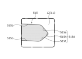
- a terminal surface 215d of the Rayleigh step 215 of the second embodiment has a substantially semicircular shape in plan view. Specifically, the terminal surface 215d has a radius of curvature R3 and is continuous with the side surfaces 215b and 215c.
- the radius of curvature R4 of the curved surface portion 415h is smaller than the radius of curvature R5 of the curved surface portion 415j, it is easier to generate positive pressure in the vicinity of the curved surface portion 415h than in the curved surface portion 415j.
- the curved surface portion 415j is curved more gently than the curved surface portion 415h, it is possible to smoothly move the sealed fluid F toward the inclined surface portion 415e while suppressing the generation of positive pressure at the curved surface portion 415j. can be done.
Abstract
Provided is a sliding component capable of discharging contamination to a gap between sliding surfaces. A sliding component 10 which is disposed at a relatively rotating position of a rotary machine, which relatively slides with respect to another sliding component 20, and which has a sliding surface 11 provided with a fluid introduction groove 14 communicating with at least one from among a space on a sealed fluid side and a space on a leakage side and a dynamic pressure generation groove 15 communicating with the fluid introduction groove 14 and extending in the circumferential direction. Both side edges 15e, 15f and a terminal edge 15g of the dynamic pressure generation groove 15 are continuous in a curved form in plan view.
Description
本発明は、回転機械の回転軸とケースとの間を軸封する軸封装置に用いられる摺動部品に関する。
The present invention relates to a sliding component used in a shaft sealing device that seals between a rotating shaft of a rotating machine and a case.
回転機械において回転軸周辺の被密封流体の漏れを防止する軸封装置として、例えば相対回転し摺動面同士が摺動する一対の環状の摺動部品からなるメカニカルシールが知られている。このようなメカニカルシールにおいては、近年、環境対策等のために摺動により失われるエネルギーの低減が望まれており、摺動部品の摺動面に被密封液体側に連通するとともに摺動面において一端が閉塞する正圧発生溝を設けているものがある。
A mechanical seal consisting of a pair of annular sliding parts that rotate relative to each other and whose sliding surfaces slide against each other is known as a shaft sealing device that prevents leakage of the sealed fluid around the rotating shaft in a rotating machine. In such mechanical seals, in recent years, it has been desired to reduce the energy lost due to sliding in order to take measures against the environment. Some have positive pressure generating grooves closed at one end.
例えば、特許文献1に示されるメカニカルシールは、一方の摺動部品の摺動面において、径方向に延び被密封液体側に連通し漏れ側に連通しない流体導入溝と、該流体導入溝に連通して相対回転方向に延設される正圧発生溝とから構成される正圧発生機構が、ランド部を介し周方向に複数設けられている。これによれば、摺動部品の相対回転時には、被密封流体が流体導入溝を経て正圧発生溝に導入され、正圧発生溝の相対回転方向の端部の壁部に被密封流体が集中して正圧が発生して摺動面同士が離間するとともに、摺動面に被密封流体の流体膜が形成されることで潤滑性が向上し、低摩擦化を実現している。
For example, the mechanical seal disclosed in Patent Document 1 has, on the sliding surface of one of the sliding parts, a fluid introduction groove that extends in the radial direction and communicates with the sealed liquid side but does not communicate with the leakage side, and communicates with the fluid introduction groove. A plurality of positive pressure generating mechanisms including positive pressure generating grooves extending in the direction of relative rotation are provided in the circumferential direction via lands. According to this, during the relative rotation of the sliding parts, the sealed fluid is introduced into the positive pressure generating groove through the fluid introduction groove, and the sealed fluid concentrates on the wall portion of the end portion of the positive pressure generating groove in the relative rotation direction. As a result, a positive pressure is generated to separate the sliding surfaces, and a fluid film of the sealed fluid is formed on the sliding surfaces, thereby improving lubricity and realizing low friction.
特許文献1の摺動部品にあっては、被密封流体は正圧発生溝の一対の側面に沿って流れた後、終端面およびその近傍から摺動部品間に供給されることで、摺動部品間を低摩擦化することができるようになっている。しかしながら、特許文献1のような摺動部品にあっては、正圧発生溝を構成する側面と終端面との境界部分には略直角をなす角部が形成されており、被密封流体が流体導入溝から正圧発生溝の終端部に向けて移動する際にこの角部近傍で渦が生じること等により、該角部において被密封流体の流れが生じにくい部分が生じ、当該部分に被密封流体に含まれるコンタミが停滞・蓄積される虞があった。この正圧発生溝の角部に蓄積されたコンタミは、正圧発生溝の性能に影響を及ぼす、またはアブレッシブ摩耗を生じさせやすく摺動面の破損を引き起こす等の虞がある。尚、本願において、「コンタミ」とはコンタミネーション(contamination)の略称であり、多細粒子状の導電性異物などの「粒子状異物」を意味する。
In the sliding component of Patent Document 1, the sealed fluid flows along the pair of side surfaces of the positive pressure generating groove, and then is supplied between the sliding component from the end surface and the vicinity thereof, thereby causing sliding. Friction between parts can be reduced. However, in the sliding part as disclosed in Patent Document 1, a substantially right-angled corner is formed at the boundary between the side surface of the positive pressure generating groove and the end surface. When moving from the introduction groove toward the terminal end of the positive pressure generating groove, a vortex is generated near the corner, resulting in a portion where it is difficult for the sealed fluid to flow at the corner. There is a risk that contaminants contained in the fluid will stagnate and accumulate. Contaminants accumulated in the corners of the positive pressure generating grooves may affect the performance of the positive pressure generating grooves, or may cause abrasive wear and breakage of the sliding surfaces. In the present application, "contamination" is an abbreviation of "contamination" and means "particulate foreign matter" such as multifine particulate conductive foreign matter.
本発明は、このような問題点に着目してなされたもので、コンタミを摺動面間に排出できる摺動部品を提供することを目的とする。
The present invention has been made with a focus on such problems, and an object thereof is to provide a sliding component that can discharge contamination between sliding surfaces.
前記課題を解決するために、本発明の摺動部品は、
回転機械の相対回転する箇所に配置され他の摺動部品と相対摺動し、その摺動面には、被密封流体側または漏れ側の少なくとも一方の空間に連通する流体導入溝と、前記流体導入溝に連通して周方向に延設される動圧発生溝と、が設けられた摺動部品であって、
前記動圧発生溝の両側縁と閉塞縁とは、平面視で湾曲して連続している。
これによれば、動圧発生溝に正圧が発生すると、動圧発生溝の閉塞部において、流体が両側縁と閉塞縁とが連続する湾曲部分に沿って円滑に移動し、閉塞縁とその近傍から摺動面間に流出するため、流体に含まれるコンタミを動圧発生溝の閉塞部で蓄積させることなく、摺動面間に排出することができる。 In order to solve the above problems, the sliding component of the present invention is
The sliding surface of the rotating machine is provided with a fluid introduction groove that communicates with at least one of the sealed fluid side and the leakage side, A sliding component provided with a dynamic pressure generating groove that extends in the circumferential direction and communicates with the introduction groove,
Both side edges and the closed edge of the dynamic pressure generating groove are curved and continuous in a plan view.
According to this, when a positive pressure is generated in the dynamic pressure generating groove, the fluid smoothly moves along the curved portion where the both side edges and the closed edge continue in the closed portion of the dynamic pressure generating groove. Since the fluid flows out between the sliding surfaces from the vicinity, the contamination contained in the fluid can be discharged between the sliding surfaces without accumulating at the closed portions of the dynamic pressure generating grooves.
前記側縁から深さ方向に延びる側面と前記閉塞縁から深さ方向に延びる閉塞面が湾曲して連続していてもよい。
これによれば、側縁から深さ方向に延びる側面と閉塞縁から深さ方向に延びる閉塞面が湾曲して連続しているため、動圧発生溝の閉塞部の深さ方向に亘って流体を円滑に移動させることができる。 A side surface extending in the depth direction from the side edge and a closed surface extending in the depth direction from the closed edge may be curved and continuous.
According to this configuration, since the side surface extending in the depth direction from the side edge and the closed surface extending in the depth direction from the closed edge are curved and continuous, the fluid flow is prevented from flowing in the depth direction of the closed portion of the dynamic pressure generating groove. can be moved smoothly.
前記両側面と前記閉塞面とが平面視で曲率半径を有する曲面により連続していてもよい。
これによれば、コンタミを1つの曲率の曲面に沿って円滑に移動させることができる。 The both side surfaces and the closed surface may be continuous with a curved surface having a radius of curvature in plan view.
According to this, the contaminants can be smoothly moved along the curved surface with one curvature.
これによれば、コンタミを1つの曲率の曲面に沿って円滑に移動させることができる。 The both side surfaces and the closed surface may be continuous with a curved surface having a radius of curvature in plan view.
According to this, the contaminants can be smoothly moved along the curved surface with one curvature.
前記閉塞面は、曲率半径を有する曲面であってもよい。
これによれば、コンタミを1つの曲率の閉塞面に沿って円滑に移動させることができる。 The closed surface may be a curved surface having a radius of curvature.
According to this, the contaminants can be smoothly moved along the closed surface with one curvature.
これによれば、コンタミを1つの曲率の閉塞面に沿って円滑に移動させることができる。 The closed surface may be a curved surface having a radius of curvature.
According to this, the contaminants can be smoothly moved along the closed surface with one curvature.
前記動圧発生溝を構成する底面と前記閉塞面とは断面視で湾曲して連続している。
これによれば、閉塞面の近傍では、底面により摺動面側に向けて流体の移動が案内されるため、コンタミを摺動面間に排出しやすい。 The bottom surface forming the dynamic pressure generating groove and the closed surface are curved and continuous in a cross-sectional view.
According to this, in the vicinity of the closed surface, movement of the fluid is guided toward the sliding surface side by the bottom surface, so that contaminants can be easily discharged between the sliding surfaces.
前記流体導入溝は前記被密封流体側の空間に連通しており、前記摺動面には、前記漏れ側の空間に連通し、前記被密封流体側の空間に連通しないスパイラル溝が設けられていてもよい。
これによれば、スパイラル溝により漏れ側の流体が摺動面間に供給されるため、摺動面間に排出されたコンタミが漏れ側の空間に移動することが抑制される。 The fluid introduction groove communicates with the space on the side of the sealed fluid, and the sliding surface is provided with a spiral groove that communicates with the space on the leakage side and does not communicate with the space on the side of the sealed fluid. may
According to this, since the fluid on the leakage side is supplied between the sliding surfaces by the spiral groove, the contaminants discharged between the sliding surfaces are suppressed from moving to the space on the leakage side.
本発明に係る摺動部品を実施するための形態を実施例に基づいて以下に説明する。
A mode for carrying out the sliding component according to the present invention will be described below based on an embodiment.
実施例1に係る摺動部品につき、図1から図5を参照して説明する。尚、本実施例においては、メカニカルシールの内空間S1に被密封流体Fが存在し、外空間S2に大気Aが存在しており、メカニカルシールを構成する摺動部品の内径側を被密封流体側(高圧側)、外径側を漏れ側(低圧側)として説明する。また、説明の便宜上、図面において、摺動面に形成される溝等にドットを付すこともある。
A sliding component according to Example 1 will be described with reference to FIGS. 1 to 5. FIG. In this embodiment, the sealed fluid F exists in the inner space S1 of the mechanical seal, and the atmosphere A exists in the outer space S2. side (high pressure side) and the outer diameter side as the leakage side (low pressure side). Also, for convenience of explanation, dots may be attached to grooves formed on the sliding surface in the drawings.
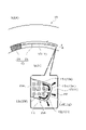
図1に示される自動車用のメカニカルシールは、摺動面の内径側から外径側に向かって漏れようとする内空間S1内の被密封流体Fを密封し外空間S2が大気Aに通ずるアウトサイド形のものである。尚、本実施例では、被密封流体Fが高圧の液体であり、大気Aが被密封流体Fよりも低圧の気体である形態を例示する。
The automotive mechanical seal shown in FIG. 1 seals the sealed fluid F in the inner space S1 that is about to leak from the inner diameter side of the sliding surface toward the outer diameter side, and the outer space S2 communicates with the atmosphere A. It has a side shape. In this embodiment, the sealed fluid F is a high-pressure liquid, and the atmosphere A is a gas with a pressure lower than that of the sealed fluid F. As shown in FIG.
メカニカルシールは、他方の摺動部品としての回転密封環20と、一方の摺動部品としての静止密封環10と、から主に構成されている。回転密封環20は円環状をなし、回転軸1にスリーブ2を介して回転軸1と共に回転可能な状態で設けられている。静止密封環10は円環状をなし、被取付機器のハウジング4に固定されたシールカバー5に非回転状態かつ軸方向に移動可能な状態で設けられている。弾性部材7によって静止密封環10が軸方向に付勢されることにより、静止密封環10の摺動面11と回転密封環20の摺動面21とが互いに密接摺動するようになっている。尚、回転密封環20の摺動面21は平坦面となっており、この平坦面には溝等の凹み部が設けられていない。
A mechanical seal is mainly composed of a rotary seal ring 20 as the other sliding component and a stationary seal ring 10 as one sliding component. The rotary seal ring 20 has an annular shape and is provided on the rotary shaft 1 through the sleeve 2 so as to be rotatable together with the rotary shaft 1 . The stationary seal ring 10 has an annular shape and is provided in a non-rotatable and axially movable state on a seal cover 5 fixed to a housing 4 of a device to which it is attached. The stationary seal ring 10 is urged in the axial direction by the elastic member 7, so that the sliding surface 11 of the stationary seal ring 10 and the sliding surface 21 of the rotary seal ring 20 closely slide against each other. . The sliding surface 21 of the rotary seal ring 20 is a flat surface, and this flat surface is not provided with recesses such as grooves.
静止密封環10及び回転密封環20は、代表的にはSiC(硬質材料)同士またはSiC(硬質材料)とカーボン(軟質材料)の組み合わせで形成されるが、これに限らず、摺動材料はメカニカルシール用摺動材料として使用されているものであれば適用可能である。尚、SiCとしては、ボロン、アルミニウム、カーボン等を焼結助剤とした焼結体をはじめ、成分、組成の異なる2種類以上の相からなる材料、例えば、黒鉛粒子の分散したSiC、SiCとSiからなる反応焼結SiC、SiC-TiC、SiC-TiN等があり、カーボンとしては、炭素質と黒鉛質の混合したカーボンをはじめ、樹脂成形カーボン、焼結カーボン等が利用できる。また、上記摺動材料以外では、金属材料、樹脂材料、表面改質材料(コーティング材料)、複合材料等も適用可能である。
The stationary seal ring 10 and the rotary seal ring 20 are typically formed of a combination of SiC (hard material) or SiC (hard material) and carbon (soft material). Any material that is used as a sliding material for mechanical seals can be applied. Examples of SiC include sintered bodies using boron, aluminum, carbon, etc. as sintering aids, and materials composed of two or more phases with different components and compositions, such as SiC and SiC in which graphite particles are dispersed. There are reaction-sintered SiC, SiC-TiC, SiC-TiN, etc. made of Si, and as the carbon, resin-molded carbon, sintered carbon, etc. can be used, as well as mixed carbonaceous and graphite carbon. Metal materials, resin materials, surface modification materials (coating materials), composite materials, etc. are also applicable in addition to the sliding materials described above.
図2及び図3に示されるように、静止密封環10に対して相手側密封環である回転密封環20が実線矢印で示すように時計回りに相対摺動するようになっている。
As shown in FIGS. 2 and 3, the rotary seal ring 20, which is the mating seal ring, slides clockwise relative to the stationary seal ring 10 as indicated by the solid arrow.
静止密封環10の摺動面11には、内径側において複数の動圧発生機構13が周方向に均等に配設(本実施例では8個)されている。
On the sliding surface 11 of the stationary seal ring 10, a plurality of dynamic pressure generating mechanisms 13 are evenly arranged in the circumferential direction (eight in this embodiment) on the inner diameter side.
また、摺動面11における動圧発生機構13以外の部分は平坦面を成すランド12となっている。ランド12の平坦面が回転密封環20の摺動面21と実質的に摺動する摺動面として機能している。
In addition, the portion of the sliding surface 11 other than the dynamic pressure generating mechanism 13 is a land 12 forming a flat surface. The flat surface of the land 12 functions as a sliding surface that substantially slides against the sliding surface 21 of the rotary seal ring 20 .
図3に示されるように、動圧発生機構13は、流体導入溝14と、動圧発生溝としてのレイリーステップ15と、から構成されている。流体導入溝14は内空間S1に連通して外空間S2に連通しないように径方向に延びている。レイリーステップ15は流体導入溝14の外径側から時計回り方向に静止密封環10と同心状に周方向に延びている。流体導入溝14の深さは、レイリーステップ15の深さよりも深く形成されている。
As shown in FIG. 3, the dynamic pressure generating mechanism 13 is composed of a fluid introduction groove 14 and a Rayleigh step 15 as a dynamic pressure generating groove. The fluid introduction groove 14 extends radially so as to communicate with the inner space S1 and not communicate with the outer space S2. The Rayleigh step 15 extends circumferentially concentrically with the stationary seal ring 10 in a clockwise direction from the outer diameter side of the fluid introduction groove 14 . The depth of the fluid introduction groove 14 is formed deeper than the depth of the Rayleigh step 15 .
流体導入溝14は、底面14aと、側面14b,14cと、外径側の端面14dと、から構成されている。底面14aはランド12の平坦面と平行に径方向に延びている。側面14b,14cは底面14aの周方向両端縁から立ち上がっている。外径側の端面14dは底面14aの外径端から立ち上がり側面14b,14cを連結している。側面14bにはレイリーステップ15に連通する開口14Aが形成されている。また、流体導入溝14の内径側には、内空間S1に連通する開口14Bが形成されている。尚、底面14aは、外径側に向けてランド12に近づくように、すなわち浅くなるように傾斜していてもよい。
The fluid introduction groove 14 is composed of a bottom surface 14a, side surfaces 14b and 14c, and an outer diameter side end surface 14d. The bottom surface 14 a extends radially parallel to the flat surface of the land 12 . The side surfaces 14b and 14c rise from both circumferential edges of the bottom surface 14a. An end surface 14d on the outer diameter side rises from the outer diameter end of the bottom surface 14a and connects the side surfaces 14b and 14c. An opening 14A communicating with the Rayleigh step 15 is formed in the side surface 14b. An opening 14B communicating with the inner space S1 is formed on the inner diameter side of the fluid introduction groove 14. As shown in FIG. The bottom surface 14a may be inclined toward the outer diameter side so as to approach the land 12, that is, to become shallower.
図4及び図5を参照して、レイリーステップ15は、底面15aと、側面15b,15cと、相対回転下流側の閉塞面としての終端面15dと、から主に構成されている。底面15aはランド12の平坦面と平行に径方向に延びている。側面15b,15cは底面15aの周方向両端縁からランド12の平坦面に向けて立ち上がっている。相対回転下流側の終端面15dは底面15aの周方向端縁から側面15b,15cに連続している。以下、レイリーステップ15における終端面15d近傍の部位を終端部15Aといい、終端部15Aは閉塞形状をなしている。すなわち終端部15Aは閉塞部として機能している。
4 and 5, the Rayleigh step 15 is mainly composed of a bottom surface 15a, side surfaces 15b and 15c, and an end surface 15d as a closing surface on the downstream side of relative rotation. The bottom surface 15 a extends radially parallel to the flat surface of the land 12 . The side surfaces 15b and 15c rise toward the flat surface of the land 12 from both circumferential ends of the bottom surface 15a. The terminal surface 15d on the downstream side of the relative rotation continues from the circumferential edge of the bottom surface 15a to the side surfaces 15b and 15c. A portion of the Rayleigh step 15 near the terminal surface 15d is hereinafter referred to as a terminal portion 15A, and the terminal portion 15A has a closed shape. That is, the terminal portion 15A functions as a closing portion.
図4に示されるように、側面15b,15cは、互いに平行に主に相対回転方向に延びる円弧面であり、終端面15dは主に相対回転方向と交差する方向に延びる平面である。側面15b,15cの離間幅、すなわちレイリーステップ15の径方向の幅寸法Wは周方向に一定となっている。
As shown in FIG. 4, the side surfaces 15b and 15c are arcuate surfaces extending parallel to each other mainly in the direction of relative rotation, and the end surface 15d is a plane extending mainly in the direction intersecting the direction of relative rotation. The distance between the side surfaces 15b and 15c, that is, the radial width dimension W of the Rayleigh step 15 is constant in the circumferential direction.
また、図5に示されるように、底面15aとランド12の平坦面との離間幅、すなわちレイリーステップ15の深さ寸法Dは周方向に一定となっている。
Further, as shown in FIG. 5, the distance between the bottom surface 15a and the flat surface of the land 12, that is, the depth dimension D of the Rayleigh step 15 is constant in the circumferential direction.
また、図4及び図5に示されるように、レイリーステップ15の深さ寸法Dはレイリーステップ15の幅寸法Wよりも小さい(D<W)。好ましくは、レイリーステップ15の深さ寸法Dはレイリーステップ15の幅寸法Wの1/10以下の大きさとなっている。
Also, as shown in FIGS. 4 and 5, the depth dimension D of the Rayleigh step 15 is smaller than the width dimension W of the Rayleigh step 15 (D<W). Preferably, the depth dimension D of the Rayleigh step 15 is 1/10 or less of the width dimension W of the Rayleigh step 15 .
側面15b,15cは、それらの上端、詳しくはランド12の平坦面に連なる箇所に側縁15e,15fを有し、終端面15dは、その上端、詳しくはランド12の平坦面に連なる箇所に閉塞縁としての終端縁15gを有している。言い換えれば、側面15b,15cは側縁15e,15fから深さ方向に延びており、終端面15dは終端縁15gから深さ方向に延びている。
The side surfaces 15b and 15c have side edges 15e and 15f at their upper ends, more specifically at the points where they are connected to the flat surface of the land 12, and the end surfaces 15d are closed at their upper ends, more specifically at the points where they are connected to the flat surface of the land 12. It has a terminal edge 15g as an edge. In other words, side surfaces 15b and 15c extend in depth from side edges 15e and 15f, and terminal surface 15d extends in depth from terminal edge 15g.
特に図4に示されるように、これら側縁15e,15f及び終端縁15gは平面視で湾曲して連続している。詳しくは、側縁15e,15fを有する側面15b,15cは、終端縁15gを有する終端面15dの径方向両端に対して平面視で同じ曲率半径R1を有する曲面15h,15jの上縁15m、15nにより連続している。尚、曲面15h,15jに隣接して図示されている一点鎖線の円は、曲率半径R1を説明するための仮想線である。さらに尚、以下、曲率半径を説明するために上記のような仮想線を図示することもある。
Especially, as shown in FIG. 4, these side edges 15e, 15f and terminal edge 15g are curved and continuous in plan view. Specifically, the side surfaces 15b and 15c having the side edges 15e and 15f are curved surfaces 15h and 15j having the same radius of curvature R1 in plan view as the radial ends of the terminal surface 15d having the terminal edge 15g. are continuous by The dashed-dotted circles shown adjacent to the curved surfaces 15h and 15j are imaginary lines for explaining the radius of curvature R1. Furthermore, hereinafter, such imaginary lines as described above may be illustrated in order to explain the radius of curvature.
外径側の曲面15hは、平面視で相対回転下流外径側、すなわち時計回り方向の外径側に凸をなしている。内径側の曲面15jは平面視で相対回転下流内径側、すなわち時計回り方向内径側に凸をなしている。言い換えれば、曲面15h,15jの曲率中心はレイリーステップ15の内側に配置されている。
The curved surface 15h on the outer diameter side is convex on the outer diameter side downstream of the relative rotation in plan view, that is, on the outer diameter side in the clockwise direction. The curved surface 15j on the inner diameter side is convex toward the inner diameter side of the relative rotation downstream, that is, toward the inner diameter side in the clockwise direction in plan view. In other words, the centers of curvature of the curved surfaces 15 h and 15 j are arranged inside the Rayleigh step 15 .
また、特に図5に示されるように、底面15aと終端面15dとは断面視で湾曲して連続している。詳しくは、底面15aと終端面15dとは断面視で曲率半径R2を有する曲面15kにより連続している。曲面15kは、断面視で相対回転下流側深さ方向、すなわち時計回り方向且つ回転密封環20の摺動面21から離れる方向に向けて凸をなしている。言い換えれば、曲面15kの曲率中心はレイリーステップ15の内側に配置されている。
In addition, as particularly shown in FIG. 5, the bottom surface 15a and the terminal surface 15d are curved and continuous in a cross-sectional view. More specifically, the bottom surface 15a and the end surface 15d are connected by a curved surface 15k having a radius of curvature R2 in a cross-sectional view. The curved surface 15k is convex in the depth direction of the downstream side of relative rotation, that is, in the clockwise direction and in the direction away from the sliding surface 21 of the rotary seal ring 20 when viewed in cross section. In other words, the center of curvature of curved surface 15 k is located inside Rayleigh step 15 .
また、曲面15h,15jの曲率半径R1は、曲面15kの曲率半径R2よりも大きい(R1>R2)。すなわち、曲面15h,15jは曲面15kよりも緩やかに湾曲している。
Also, the radius of curvature R1 of the curved surfaces 15h and 15j is larger than the radius of curvature R2 of the curved surface 15k (R1>R2). That is, the curved surfaces 15h and 15j are curved more gently than the curved surface 15k.
また、曲率半径R1は、レイリーステップ15の深さ寸法Dの1/3~3倍の範囲の寸法となっている。
Also, the radius of curvature R1 is a dimension in the range of 1/3 to 3 times the depth dimension D of the Rayleigh step 15.
また、曲率半径R1は、10μm以上である(R1≧10μm)。
Also, the radius of curvature R1 is 10 μm or more (R1≧10 μm).
次いで、静止密封環10と回転密封環20との相対回転時の動作について図3~図5を用いて説明する。尚、図3の被密封流体Fや大気Aの流れについては、回転密封環20の相対回転速度を特定せずに概略的に示している。
Next, the operation during relative rotation between the stationary seal ring 10 and the rotary seal ring 20 will be described with reference to FIGS. 3 to 5. FIG. The flow of the sealed fluid F and the air A in FIG. 3 is schematically shown without specifying the relative rotational speed of the rotary seal ring 20 .
まず、回転密封環20が回転していない停止時には、被密封流体Fが流体導入溝14内に流入している。尚、弾性部材7によって静止密封環10が回転密封環20側に付勢されているので摺動面11,21同士は接触状態となっており、摺動面11,21間の被密封流体Fが外空間S2に漏れ出す量はほぼない。
First, when the rotary seal ring 20 is not rotating and is stopped, the sealed fluid F flows into the fluid introduction groove 14 . Since the stationary seal ring 10 is urged toward the rotary seal ring 20 by the elastic member 7, the sliding surfaces 11 and 21 are in contact with each other, and the fluid F to be sealed between the sliding surfaces 11 and 21 is kept in contact with each other. There is almost no amount of leaking into the outer space S2.
図3に示されるように、回転密封環20が静止密封環10に対して相対回転した状態においては、レイリーステップ15内の被密封流体Fが摺動面21とのせん断により回転密封環20の回転方向に追随移動することにより、内空間S1の被密封流体Fが流体導入溝14に引き込まれる。すなわち、流体導入溝14内では、被密封流体Fが矢印H1に示すように流体導入溝14からレイリーステップ15における相対回転方向の下流側の終端部15Aに向かって移動する。
As shown in FIG. 3, when the rotary seal ring 20 rotates relative to the stationary seal ring 10, the sealed fluid F in the Rayleigh step 15 shears against the sliding surface 21, causing the rotary seal ring 20 to move. The sealed fluid F in the inner space S<b>1 is drawn into the fluid introduction groove 14 by following the movement in the rotational direction. That is, in the fluid introduction groove 14, the sealed fluid F moves from the fluid introduction groove 14 toward the downstream end portion 15A in the relative rotation direction of the Rayleigh step 15 as indicated by the arrow H1.
レイリーステップ15の終端部15Aに向かって移動した被密封流体Fは、レイリーステップ15の終端部15A及びその近傍で圧力が高められる。すなわちレイリーステップ15の終端部15A及びその近傍で正圧が発生する。
The pressure of the sealed fluid F that has moved toward the end portion 15A of the Rayleigh step 15 is increased at and near the end portion 15A of the Rayleigh step 15. That is, a positive pressure is generated at the end portion 15A of the Rayleigh step 15 and its vicinity.
レイリーステップ15の深さは浅いため、回転密封環20の回転速度が低速につき被密封流体Fの移動量が少なくてもレイリーステップ15の終端部15A及びその近傍にて正圧が発生する。
Since the depth of the Rayleigh step 15 is shallow, positive pressure is generated at the end portion 15A of the Rayleigh step 15 and its vicinity even if the amount of movement of the sealed fluid F is small due to the low rotation speed of the rotary seal ring 20 .
また、レイリーステップ15の終端部15A及びその近傍で発生した正圧による力により、摺動面11,21間が若干離間される(図5参照)。これにより、摺動面11,21間には、主に矢印H2に示す動圧発生機構13内の被密封流体Fが流入する。このように摺動面11,21間に被密封流体Fが介在することにより低速回転時においても潤滑性が向上し、摺動面11,21同士の摩耗を抑制することができる。尚、摺動面11,21同士の浮上距離が僅かであるため、外空間S2に漏れ出す被密封流体Fは少ない。また、流体導入溝14が設けられているため、被密封流体Fを多量に保持することができる。
In addition, the sliding surfaces 11 and 21 are slightly separated from each other due to the positive pressure generated at the end portion 15A of the Rayleigh step 15 and its vicinity (see FIG. 5). As a result, between the sliding surfaces 11 and 21, the sealed fluid F in the dynamic pressure generating mechanism 13 mainly shown by the arrow H2 flows. By interposing the sealed fluid F between the sliding surfaces 11 and 21 in this manner, lubricity is improved even during low-speed rotation, and wear between the sliding surfaces 11 and 21 can be suppressed. Since the floating distance between the sliding surfaces 11 and 21 is small, the amount of the sealed fluid F that leaks into the outer space S2 is small. Further, since the fluid introduction groove 14 is provided, a large amount of the sealed fluid F can be retained.
図4に示されるように、レイリーステップ15の終端部15Aにおいて側面15b,15cに沿って移動する被密封流体Fは、平面視で湾曲する曲面15h,15jに沿って移動し、一部が曲面15h,15jを越えて摺動面11,21間に流入するとともに、その他の一部がレイリーステップ15の幅方向中央部に集められ、終端面15dを越えて摺動面11,21間に流入する。
As shown in FIG. 4, the sealed fluid F moving along the side surfaces 15b and 15c at the end portion 15A of the Rayleigh step 15 moves along curved surfaces 15h and 15j that are curved in a plan view, and part of the curved surfaces Along with flowing into between the sliding surfaces 11 and 21 beyond 15h and 15j, the other part is collected in the widthwise central portion of the Rayleigh step 15 and flows into between the sliding surfaces 11 and 21 over the end surface 15d. do.
また、ミクロ的には平面視で終端部15Aにおいて被密封流体Fが最も高い圧力となる点が時間と共に幅方向に変化する。被密封流体Fは曲面15h,15j、終端面15dに沿って移動し、曲面15h,15j、終端面15dは滑らかに連なっているため、コンタミが滞ることなく、摺動面11,21間に排出されやすくなっている。
Also, microscopically, the point at which the sealed fluid F has the highest pressure in the end portion 15A in a plan view changes in the width direction with time. The sealed fluid F moves along the curved surfaces 15h, 15j and the terminal surface 15d, and since the curved surfaces 15h, 15j and the terminal surface 15d are smoothly connected, contamination is discharged between the sliding surfaces 11 and 21 without stagnation. It is easier to be
また、図5に示されるように、底面15aと終端面15dとは曲面15kにより連続しているため、被密封流体Fは、摺動面11,21間に向けて円滑に移動することができる。
Further, as shown in FIG. 5, since the bottom surface 15a and the end surface 15d are connected by the curved surface 15k, the sealed fluid F can smoothly move between the sliding surfaces 11 and 21. .
以上説明したように、レイリーステップ15の側縁15e,15fと終端縁15gとは、平面視で湾曲する曲面15h,15jにより連続している。これによれば、レイリーステップ15の終端部15Aにおいて、側縁15e,15fと終端縁15gとに連続する曲面15h,15jに沿って被密封流体Fが円滑に移動するため、被密封流体Fに含まれるコンタミがレイリーステップ15の終端部15Aで蓄積されることなく、レイリーステップ15内から摺動面11,21間に排出することができる。
As described above, the side edges 15e, 15f and the terminal edge 15g of the Rayleigh step 15 are continuous with curved surfaces 15h, 15j curved in a plan view. According to this, at the end portion 15A of the Rayleigh step 15, the sealed fluid F smoothly moves along the curved surfaces 15h and 15j that are continuous with the side edges 15e and 15f and the end edge 15g. Contaminants contained therein can be discharged from inside the Rayleigh step 15 between the sliding surfaces 11 and 21 without accumulating at the end portion 15A of the Rayleigh step 15 .
言い換えれば、側縁15e,15fと終端縁15gとの間で平面視において角部が形成されないため、レイリーステップ15の終端部15Aにおける側縁15e,15fと終端縁15gとの間で渦が生じにくく、レイリーステップ15の終端部15Aにおいてコンタミが蓄積されやすい領域が形成されることを抑制できる。
In other words, since corners are not formed between the side edges 15e, 15f and the terminal edge 15g in plan view, a vortex is generated between the side edges 15e, 15f and the terminal edge 15g at the terminal part 15A of the Rayleigh step 15. Therefore, it is possible to suppress the formation of a region where contamination is likely to be accumulated at the end portion 15A of the Rayleigh step 15 .
また、側縁15e,15fから底面15aに向けて深さ方向に延びる側面15b,15cと、終端縁15gから底面15aに向けて深さ方向に延びる終端面15dと、が湾曲して連続しているため、レイリーステップ15の終端部15Aの深さ方向に亘って被密封流体Fを円滑に移動させることができる。
Further, side surfaces 15b and 15c extending in the depth direction from the side edges 15e and 15f toward the bottom surface 15a and a terminal surface 15d extending in the depth direction from the terminal edge 15g toward the bottom surface 15a are curved and continuous. Therefore, the sealed fluid F can be smoothly moved in the depth direction of the end portion 15</b>A of the Rayleigh step 15 .
また、両側面15b,15cと終端面15dとが平面視で1つの曲率半径R1を有する曲面15h,15jにより連続している。これによれば、コンタミを1つの曲率の曲面15h,15jに沿って円滑に移動させ、一部を側面15b,15cから摺動面11,21間に排出させながらレイリーステップ15の幅方向中央部に集め、残りの一部を終端面15dから摺動面11,21間に排出させることができる。
In addition, both side surfaces 15b and 15c and the end surface 15d are continuous by curved surfaces 15h and 15j having one radius of curvature R1 in plan view. According to this, the contaminants are smoothly moved along the curved surfaces 15h and 15j with one curvature, and part of the contaminants are discharged from the side surfaces 15b and 15c to between the sliding surfaces 11 and 21, while the center portion in the width direction of the Rayleigh step 15 , and the remaining portion can be discharged between the sliding surfaces 11 and 21 from the terminal surface 15d.
また、レイリーステップ15を構成する底面15aと終端面15dとは断面視で湾曲して連続している。これによれば、終端面15dの近傍では、底面15aと終端面15dとの間の曲面15kにより摺動面11,21間に向けて被密封流体Fの移動が案内されるため、コンタミを摺動面11,21間に排出しやすい。言い換えれば、底面15aと終端面15dとの境界部分にコンタミが蓄積されることを抑制できる。
In addition, the bottom surface 15a and the terminal surface 15d that constitute the Rayleigh step 15 are curved and continuous in a cross-sectional view. According to this, in the vicinity of the terminal surface 15d, movement of the sealed fluid F is guided toward between the sliding surfaces 11 and 21 by the curved surface 15k between the bottom surface 15a and the terminal surface 15d. It is easy to discharge between the moving surfaces 11 and 21. In other words, it is possible to prevent contamination from accumulating at the boundary between the bottom surface 15a and the terminal surface 15d.
また、レイリーステップ15は、内空間S1に連通して外空間S2に連通しない流体導入溝14から周方向に延びている。これによれば、レイリーステップ15よりも深い溝である流体導入溝14から被密封流体Fをレイリーステップ15に安定して流すことができるようになっている。
In addition, the Rayleigh step 15 extends in the circumferential direction from the fluid introduction groove 14 communicating with the inner space S1 and not communicating with the outer space S2. According to this, the sealed fluid F can stably flow to the Rayleigh step 15 from the fluid introduction groove 14 which is deeper than the Rayleigh step 15 .
尚、本実施例1では、曲面15h,15jが平面視で1つの曲率半径R1を有する円弧状に形成されている形態を例示したが、平面視で放物線の一部、楕円の一部、正弦波の一部等の形状をなしていてもよい。
In the first embodiment, the curved surfaces 15h and 15j are formed in an arc shape having one radius of curvature R1 in plan view. It may have a shape such as a portion of a wave.
尚、本実施例1では、曲面15kが断面視で1つの曲率半径R2を有する円弧状に形成されている形態を例示したが、断面視で放物線の一部、楕円の一部、正弦波の一部等の形状をなしていてもよい。
In the first embodiment, the curved surface 15k is formed in an arc shape having one radius of curvature R2 when viewed in cross section. It may have a shape such as a part.
次に、実施例2に係る摺動部品につき、図6を参照して説明する。尚、前記実施例1と同一構成で重複する構成の説明を省略する。
Next, a sliding component according to Example 2 will be described with reference to FIG. It should be noted that descriptions of configurations that are the same as those of the first embodiment will be omitted.
本実施例2のレイリーステップ215の終端面215dは、平面視で略半円形状となっている。詳しくは、終端面215dは、1つの曲率半径R3を有しており、側面215b,215cと連続している。
A terminal surface 215d of the Rayleigh step 215 of the second embodiment has a substantially semicircular shape in plan view. Specifically, the terminal surface 215d has a radius of curvature R3 and is continuous with the side surfaces 215b and 215c.
これによれば、レイリーステップ215の側面215b,215cに沿って移動する被密封流体Fは、終端面215dによりレイリーステップ215の幅方向中央部に向けて円滑に移動しながら終端面215dを越えて摺動面11,21間(図5参照)に排出される。
According to this, the sealed fluid F moving along the side surfaces 215b and 215c of the Rayleigh step 215 smoothly moves toward the center of the width direction of the Rayleigh step 215 by the end surface 215d and crosses the end surface 215d. It is discharged between the sliding surfaces 11 and 21 (see FIG. 5).
次に、実施例3に係る摺動部品につき、図7を参照して説明する。尚、前記実施例1と同一構成で重複する構成の説明を省略する。
Next, a sliding component according to Example 3 will be described with reference to FIG. It should be noted that descriptions of configurations that are the same as those of the first embodiment will be omitted.
本実施例3のレイリーステップ315の終端面315dは、平面視で略半楕円形状となっており、側面315b,315cと連続している。これによれば、レイリーステップ315の側面315b,315cに沿って移動する被密封流体Fは、終端面315dによりレイリーステップ315の幅方向中央部に向けて円滑に移動しながら終端面315dを越えて摺動面11,21間(図5参照)に排出される。また、実施例2のレイリーステップ215に比べて最も相対回転下流側に配置される最終端部位の曲率半径が小さいため、該最終端部位で正圧を発生させやすい形状となっている。
A terminal end surface 315d of the Rayleigh step 315 of Embodiment 3 has a substantially semi-elliptical shape in plan view, and is continuous with the side surfaces 315b and 315c. According to this, the sealed fluid F moving along the side surfaces 315b and 315c of the Rayleigh step 315 smoothly moves toward the center of the width direction of the Rayleigh step 315 by the end surface 315d and crosses the end surface 315d. It is discharged between the sliding surfaces 11 and 21 (see FIG. 5). In addition, since the radius of curvature of the final end located furthest downstream of the relative rotation is smaller than that of the Rayleigh step 215 of the second embodiment, the final end is shaped to easily generate positive pressure.
次に、実施例4に係る摺動部品につき、図8を参照して説明する。尚、前記実施例1と同一構成で重複する構成の説明を省略する。
Next, a sliding component according to Example 4 will be described with reference to FIG. It should be noted that descriptions of configurations that are the same as those of the first embodiment will be omitted.
本実施例4のレイリーステップ415は、外径側の側面415bが内径側の側面415cよりも相対回転方向下流側に延びている。終端面415dは、傾斜面部415eと、曲面部415hと、曲面部415jと、から構成されている。傾斜面部415eは側面415b,415cを繋ぐように周方向に傾斜して径方向に直線状に延びている。曲面部415hは側面415bと傾斜面部415eを繋いでいる。曲面部415jは側面415cと傾斜面部415eを繋いでいる。
In the Rayleigh step 415 of the fourth embodiment, the side surface 415b on the outer diameter side extends further downstream in the relative rotation direction than the side surface 415c on the inner diameter side. 415 d of terminal surfaces are comprised from the inclined surface part 415e, the curved surface part 415h, and the curved surface part 415j. The inclined surface portion 415e is inclined in the circumferential direction so as to connect the side surfaces 415b and 415c and linearly extends in the radial direction. The curved surface portion 415h connects the side surface 415b and the inclined surface portion 415e. The curved surface portion 415j connects the side surface 415c and the inclined surface portion 415e.
外径側の曲面部415hは、1つの曲率半径R4を有し、内径側の曲面部415jは、曲率半径R4よりも大きな1つの曲率半径R5を有している(R4<R5)。
The curved surface portion 415h on the outer diameter side has one curvature radius R4, and the curved surface portion 415j on the inner diameter side has one curvature radius R5 larger than the curvature radius R4 (R4<R5).
レイリーステップ415内の被密封流体Fは、相対回転時において終端面415dの傾斜面部415eにより外径側に誘導され、主に曲面部415h近傍から摺動面11,21間(図5参照)に排出される。
The sealed fluid F in the Rayleigh step 415 is guided to the outer diameter side by the inclined surface portion 415e of the end surface 415d during relative rotation, and mainly flows from the vicinity of the curved surface portion 415h to between the sliding surfaces 11 and 21 (see FIG. 5). Ejected.
曲面部415hの曲率半径R4は曲面部415jの曲率半径R5よりも小さいため、曲面部415jに比べ曲面部415h近傍で正圧を発生させやすい。また、曲面部415jは、曲面部415hよりも緩やかに湾曲しているため、曲面部415jで正圧が発生することを抑えつつ、傾斜面部415eに向けて円滑に被密封流体Fを移動させることができる。
Since the radius of curvature R4 of the curved surface portion 415h is smaller than the radius of curvature R5 of the curved surface portion 415j, it is easier to generate positive pressure in the vicinity of the curved surface portion 415h than in the curved surface portion 415j. In addition, since the curved surface portion 415j is curved more gently than the curved surface portion 415h, it is possible to smoothly move the sealed fluid F toward the inclined surface portion 415e while suppressing the generation of positive pressure at the curved surface portion 415j. can be done.
次に、実施例5に係る摺動部品につき、図9を参照して説明する。尚、前記実施例1と同一構成で重複する構成の説明を省略する。
Next, a sliding component according to Example 5 will be described with reference to FIG. It should be noted that descriptions of configurations that are the same as those of the first embodiment will be omitted.
本実施例5のレイリーステップ515の終端面515dは、第1傾斜面部515eと、第2傾斜面部515fと、曲面部515hと、から構成されている。第1傾斜面部515eは側面515bから相対回転下流内径側に傾斜して直線状に延びている。第2傾斜面部515fは側面515cから相対回転下流外径側に傾斜して直線状に延びている。曲面部515hは第1傾斜面部515e及び第2傾斜面部515fの周方向下流側の端部に連続している。
The end surface 515d of the Rayleigh step 515 of the fifth embodiment is composed of a first inclined surface portion 515e, a second inclined surface portion 515f, and a curved surface portion 515h. The first inclined surface portion 515e extends straight from the side surface 515b while being inclined toward the inner diameter side downstream of the relative rotation. The second inclined surface portion 515f extends linearly from the side surface 515c while being inclined toward the downstream outer diameter side of the relative rotation. The curved surface portion 515h is continuous with the downstream ends in the circumferential direction of the first inclined surface portion 515e and the second inclined surface portion 515f.
レイリーステップ515内の被密封流体Fは、相対回転時において側面515b及び第2傾斜面部515fにより、終端面515dにおける第1傾斜面部515eと曲面部515hとに向けて誘導され、主に第1傾斜面部515e及び曲面部515hを越えて摺動面11,21間(図5参照)に排出される。
The sealed fluid F in the Rayleigh step 515 is guided toward the first inclined surface portion 515e and the curved surface portion 515h of the end surface 515d by the side surface 515b and the second inclined surface portion 515f during relative rotation, It is discharged between the sliding surfaces 11 and 21 (see FIG. 5) beyond the surface portion 515e and the curved surface portion 515h.
また、側面515bと第1傾斜面部515eとの境界部分、側面515cと第2傾斜面部515fとの境界部分は湾曲しており、被密封流体Fは当該境界部分を円滑に移動するため、コンタミが蓄積されることを抑制できる。尚、側面515bと第1傾斜面部515eとの境界部分、側面515cと第2傾斜面部515fとの境界部分は鈍角に連続していてもよい。
In addition, the boundary between the side surface 515b and the first inclined surface portion 515e and the boundary portion between the side surface 515c and the second inclined surface portion 515f are curved, and since the sealed fluid F smoothly moves along these boundary portions, contamination is prevented. It is possible to suppress the accumulation. The boundary portion between the side surface 515b and the first inclined surface portion 515e and the boundary portion between the side surface 515c and the second inclined surface portion 515f may continue at an obtuse angle.
次に、実施例6に係る摺動部品につき、図10を参照して説明する。尚、前記実施例1と同一構成で重複する構成の説明を省略する。
Next, a sliding component according to Example 6 will be described with reference to FIG. It should be noted that descriptions of configurations that are the same as those of the first embodiment will be omitted.
本実施例6の静止密封環10’の摺動面11には、複数の動圧発生機構13と、複数のスパイラル溝16と、が設けられている。動圧発生機構13は実施例1のメカニカルシールと同一構成である。
A plurality of dynamic pressure generating mechanisms 13 and a plurality of spiral grooves 16 are provided on the sliding surface 11 of the stationary seal ring 10' of the sixth embodiment. The dynamic pressure generating mechanism 13 has the same configuration as the mechanical seal of the first embodiment.
スパイラル16は摺動面11の外径側において周方向に均等に配設されている。摺動面11における動圧発生機構13及びスパイラル溝16以外の部分は平坦面を成すランド12となっている。詳しくは、ランド12は、周方向に隣接する動圧発生機構13の間のランド部と、周方向に隣接するスパイラル溝16の間のランド部と、径方向に離間する動圧発生機構13とスパイラル溝16との間のランド部と、を有し、これら各ランド部は、同一平面状に配置されランド12の平坦面を構成している。
The spirals 16 are evenly arranged in the circumferential direction on the outer diameter side of the sliding surface 11 . A portion of the sliding surface 11 other than the dynamic pressure generating mechanism 13 and the spiral groove 16 is a land 12 forming a flat surface. Specifically, the land 12 includes a land portion between the dynamic pressure generating mechanisms 13 adjacent in the circumferential direction, a land portion between the spiral grooves 16 adjacent in the circumferential direction, and the dynamic pressure generating mechanisms 13 spaced apart in the radial direction. and land portions between the spiral grooves 16 , and these land portions are arranged in the same plane to form the flat surface of the land 12 .
スパイラル溝16は、外径側から内径側に向けて時計回りの成分を持って傾斜しながら円弧状に延びている。このスパイラル溝16は、外空間S2に連通して内空間S1に連通しないようになっている。
The spiral groove 16 extends in an arc shape from the outer diameter side to the inner diameter side while being inclined with a clockwise component. The spiral groove 16 communicates with the outer space S2 and does not communicate with the inner space S1.
スパイラル溝16は、周方向に一定の深さに形成されている。尚、スパイラル溝16は、傾斜しながら円弧状に延びるものに限らず、直線状に延びるものであってもよい。
The spiral groove 16 is formed with a constant depth in the circumferential direction. In addition, the spiral groove 16 is not limited to extending in an arc while being inclined, and may extend in a straight line.
スパイラル溝16は、底面16aと、側面16b,16cと、端面16dと、から構成されている。底面16aはランド12の平坦面と平行に径方向に延びている。側面16b,16cは底面16aの周方向両端縁から立ち上がっている。端面16dは底面16aと側面16b,16cとの内径端同士を連結している。スパイラル溝16の外径側には、外空間S2に連通する開口16Aが形成されている。
The spiral groove 16 is composed of a bottom surface 16a, side surfaces 16b and 16c, and an end surface 16d. The bottom surface 16 a extends radially parallel to the flat surface of the land 12 . The side surfaces 16b and 16c rise from both circumferential edges of the bottom surface 16a. The end surface 16d connects the inner diameter ends of the bottom surface 16a and the side surfaces 16b and 16c. An opening 16A communicating with the outer space S2 is formed on the outer diameter side of the spiral groove 16. As shown in FIG.
次いで、静止密封環10’と回転密封環20との相対回転時の動作について説明する。
Next, the operation during relative rotation between the stationary seal ring 10' and the rotary seal ring 20 will be described.
回転密封環20が静止密封環10に対して相対回転し始めた直後の低速時においては、前述のようにレイリーステップ15の端部15A及びその近傍で正圧が発生する。
At low speed immediately after the rotary seal ring 20 starts to rotate relative to the stationary seal ring 10, positive pressure is generated at the end 15A of the Rayleigh step 15 and its vicinity as described above.
一方、スパイラル溝16においては、回転密封環20と静止密封環10’との相対回転低速時には、大気Aがスパイラル溝16内において十分に密とならず高い正圧は発生せず、スパイラル溝16によって発生される正圧による力は、レイリーステップ15の終端部15A及びその近傍で発生した正圧による力よりも相対的に小さい。よって、回転密封環20の低速回転時では、レイリーステップ15の終端部15A及びその近傍で発生した正圧による力が主体となって摺動面11,21同士を離間させるようになっている。
On the other hand, in the spiral groove 16, when the relative rotation speed between the rotary seal ring 20 and the stationary seal ring 10' is low, the atmosphere A does not become sufficiently dense in the spiral groove 16 and high positive pressure is not generated. is relatively smaller than the force due to the positive pressure generated at the terminal end 15A of the Rayleigh step 15 and its vicinity. Therefore, when the rotary seal ring 20 rotates at a low speed, the sliding surfaces 11 and 21 are separated from each other mainly by the positive pressure generated at the end portion 15A of the Rayleigh step 15 and its vicinity.
回転密封環20の相対回転速度が高まると、図10に示されるように、スパイラル溝16内の大気Aが摺動面21とのせん断により回転密封環20の回転方向に追随移動するとともに、外空間S2の大気Aがスパイラル溝16に引き込まれる。すなわち、スパイラル溝16内では、多量の大気Aが矢印L1に示すように外径側の開口16Aから内径側の端部16Bに向かって移動する。
As the relative rotational speed of the rotary seal ring 20 increases, as shown in FIG. Atmosphere A in space S2 is drawn into spiral groove 16 . That is, in the spiral groove 16, a large amount of air A moves from the outer diameter side opening 16A toward the inner diameter side end portion 16B as indicated by the arrow L1.
スパイラル溝16の内径側の端部16Bに向かって移動した大気Aは、スパイラル溝16の内径側の端部16B及びその近傍で圧力が高められる。すなわちスパイラル溝16の内径側の端部16B及びその近傍で正圧が発生する。
The atmosphere A that has moved toward the inner diameter side end 16B of the spiral groove 16 is increased in pressure at the inner diameter side end 16B of the spiral groove 16 and its vicinity. That is, a positive pressure is generated at the end portion 16B on the inner diameter side of the spiral groove 16 and its vicinity.
このように、レイリーステップ15の終端部15A及びその近傍で発生した正圧による力に、スパイラル溝16の内径側の端部16B及びその近傍で発生した正圧による力が加わり、低速時と比べ摺動面11,21間がさらに離間する。これにより、摺動面11,21間には、主に矢印L2に示すスパイラル溝16内の大気Aが流入する。
In this way, the force due to the positive pressure generated at and near the end portion 15A of the Rayleigh step 15 is added to the force due to the positive pressure generated at and near the end portion 16B on the inner diameter side of the spiral groove 16. The distance between the sliding surfaces 11 and 21 is further increased. As a result, between the sliding surfaces 11 and 21, mainly the atmosphere A in the spiral groove 16 indicated by the arrow L2 flows.
矢印L2に示すスパイラル溝16内の大気Aは、スパイラル溝16の内径側の端部16B近傍の被密封流体Fを内空間S1側に押し戻すように作用するので、スパイラル溝16内や外空間S2に漏れ出す被密封流体Fは少ない。
The atmosphere A in the spiral groove 16 indicated by the arrow L2 acts to push back the sealed fluid F in the vicinity of the end portion 16B on the inner diameter side of the spiral groove 16 toward the inner space S1. A small amount of the sealed fluid F leaks out.
本実施例のメカニカルシールは、高速回転時において、スパイラル溝16全体による正圧発生能力が、動圧発生機構13全体による正圧発生能力よりも十分に大きく設計されているため、最終的には、摺動面11,21間には大気Aのみが存在した状態、すなわち気体潤滑となる。
The mechanical seal of this embodiment is designed such that the positive pressure generating capability of the entire spiral groove 16 is sufficiently larger than the positive pressure generating capability of the entire dynamic pressure generating mechanism 13 during high-speed rotation. , the state in which only the atmosphere A exists between the sliding surfaces 11 and 21, that is, gas lubrication.
また、内空間S1の被密封流体Fは液体であり、漏れ側である外空間S2の流体は大気A、すなわち気体であり、低速回転時には、液体により摺動面11,21間の潤滑を行い、高速回転時には気体により摺動面11,21間の潤滑を行うことができる。言い換えれば、静止密封環10と回転密封環20との相対回転速度に応じて摺動面11,21間の潤滑を適切に行うことができるようになっている。
The sealed fluid F in the inner space S1 is a liquid, and the fluid in the outer space S2, which is the leak side, is the air A, that is, a gas. , the gas can lubricate the sliding surfaces 11 and 21 during high-speed rotation. In other words, the lubrication between the sliding surfaces 11 and 21 can be properly performed according to the relative rotational speed between the stationary seal ring 10 and the rotary seal ring 20 .
次に、実施例7に係るメカニカルシールにつき、図11を参照して説明する。尚、前記実施例1と同一構成で重複する構成の説明を省略する。
Next, a mechanical seal according to Example 7 will be described with reference to FIG. It should be noted that descriptions of configurations that are the same as those of the first embodiment will be omitted.
本実施例7のメカニカルシールは、静止密封環の摺動面の外径側に流体導入溝140及び動圧発生溝150を有する動圧発生機構130が形成されている。静止密封環10と回転密封環20との相対回転時の動作は、実施例1と内外径が変わった以外は略同様であるため、その説明を省略する。
In the mechanical seal of Embodiment 7, a dynamic pressure generating mechanism 130 having a fluid introduction groove 140 and a dynamic pressure generating groove 150 is formed on the outer diameter side of the sliding surface of the stationary seal ring. The operation during relative rotation between the stationary seal ring 10 and the rotary seal ring 20 is substantially the same as in the first embodiment, except that the inner and outer diameters are different, so the description thereof will be omitted.
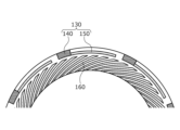
次に、実施例8に係るメカニカルシールにつき、図12を参照して説明する。尚、前記実施例6と同一構成で重複する構成の説明を省略する。
Next, a mechanical seal according to Example 8 will be described with reference to FIG. In addition, the description of the configuration that is the same as that of the sixth embodiment will be omitted.
本実施例8のメカニカルシールは、静止密封環の摺動面の外径側に流体導入溝140及び動圧発生溝150を有する動圧発生機構130が形成され、内径側にスパイル溝160が形成されている。静止密封環10と回転密封環20との相対回転時の動作は、実施例6と内外径が変わった以外は略同様であるため、その説明を省略する。
In the mechanical seal of the eighth embodiment, a dynamic pressure generating mechanism 130 having a fluid introduction groove 140 and a dynamic pressure generating groove 150 is formed on the outer diameter side of the sliding surface of the stationary seal ring, and a spiral groove 160 is formed on the inner diameter side. It is The operation during relative rotation between the stationary seal ring 10 and the rotary seal ring 20 is substantially the same as that of the sixth embodiment except that the inner and outer diameters are different, so the description thereof will be omitted.
以上、本発明の実施例を図面により説明してきたが、具体的な構成はこれら実施例に限られるものではなく、本発明の要旨を逸脱しない範囲における変更や追加があっても本発明に含まれる。
Although the embodiments of the present invention have been described above with reference to the drawings, the specific configuration is not limited to these embodiments, and any changes or additions within the scope of the present invention are included in the present invention. be
例えば、前記実施例では、摺動部品として、自動車用のメカニカルシールを例に説明したが、一般産業機械等の他のメカニカルシールであってもよい。
For example, in the above embodiments, mechanical seals for automobiles have been described as examples of sliding parts, but other mechanical seals such as those for general industrial machinery may also be used.
また、前記実施例1~8では、動圧発生溝及び流体導入溝を静止密封環に設ける例について説明したが、動圧発生溝及び流体導入溝を回転密封環に設けてもよい。言い換えると、本発明の摺動部品は静止密封環でもあっても回転密封環であってもよい。
In addition, in Examples 1 to 8, examples in which the dynamic pressure generating grooves and the fluid introduction grooves are provided in the stationary seal ring have been described, but the dynamic pressure generating grooves and the fluid introduction grooves may be provided in the rotary seal ring. In other words, the sliding component of the present invention may be a stationary seal ring or a rotating seal ring.
また、前記実施例1~8では、被密封流体側を高圧側、漏れ側を低圧側として説明してきたが、被密封流体側と漏れ側とは略同じ圧力であってもよい。被密封流体側と漏れ側とが略同じ圧力である場合、漏れ側の動圧発生溝を被密封流体側の動圧発生溝よりも深く形成し、低速回転時に動圧発生溝で正圧を発生させ、高速回転時に動圧発生溝で正圧を発生させることが好ましい。
In addition, in the above embodiments 1 to 8, the sealed fluid side is assumed to be the high pressure side and the leak side is assumed to be the low pressure side, but the sealed fluid side and the leak side may have substantially the same pressure. When the pressure on the sealed fluid side and the leak side is approximately the same, the dynamic pressure generating groove on the leak side is formed deeper than the dynamic pressure generating groove on the sealed fluid side, and positive pressure is generated in the dynamic pressure generating groove during low-speed rotation. It is preferable to generate positive pressure in the dynamic pressure generating grooves during high-speed rotation.
また、前記実施例1~8では、被密封流体Fは高圧の液体と説明したが、これに限らず気体または低圧の液体であってもよいし、液体と気体が混合したミスト状であってもよい。
In the first to eighth embodiments, the sealed fluid F is a high-pressure liquid, but it is not limited to this, and may be a gas or a low-pressure liquid, or may be a mist mixture of liquid and gas. good too.
また、前記実施例1~8では、漏れ側の流体は低圧の気体である大気Aであると説明したが、これに限らず液体または高圧の気体であってもよいし、液体と気体が混合したミスト状であってもよい。
Further, in Examples 1 to 8, the fluid on the leak side was explained to be the atmosphere A, which is a low-pressure gas. It may be in the form of a mist.
また、前記実施例1~8では、流体導入溝および動圧発生溝は被密封流体F側の空間S1に連通するように設けられる形態を説明したが、これに限らず漏れ側の空間S2に連通するように設けられてもよい。
In the first to eighth embodiments, the fluid introduction groove and the dynamic pressure generating groove are provided so as to communicate with the space S1 on the side of the sealed fluid F. It may be provided so as to communicate with it.
また、前記実施例1~8では、レイリーステップが円弧状に延びる形態を例示したが、直線状に延びるものであってもよい。またレイリーステップは、静止密封環と同心状に設けられるものに限られず、周方向に傾斜していてもよい。すなわち、側面は主に相対回転方向に延び、閉塞面は主に相対回転方向と交差する方向に延びていればよい。
Further, in Examples 1 to 8, the Rayleigh step extends in an arc shape, but it may extend in a straight line. Moreover, the Rayleigh step is not limited to being provided concentrically with the stationary seal ring, and may be inclined in the circumferential direction. In other words, it is sufficient that the side surfaces extend mainly in the direction of relative rotation, and the closing surface extends mainly in the direction crossing the direction of relative rotation.
また、前記実施例1~8では、レイリーステップの両側面が両側縁から垂直に深さ方向に延びる形態を例示したが、例えば、両側面の幅が両側縁から深さ方向に幅狭になるように傾斜してもよい。
In Examples 1 to 8, both side surfaces of the Rayleigh step extend vertically from both side edges in the depth direction. You may incline as follows.
また、前記実施例1~8では、レイリーステップの閉塞面が閉塞縁から底面側の曲面まで垂直に延びる形態を例示したが、例えば、閉塞縁から相対回転上流側に向けて浅くなるように傾斜して底面側の曲面まで延びていてもよい。
Further, in Examples 1 to 8, the closed surface of the Rayleigh step extends vertically from the closed edge to the curved surface on the bottom side. and may extend to the curved surface on the bottom side.
また、前記実施例1~8では、レイリーステップの底面がランドの平坦面と平行に延びている形態を例示したが、これに限られず、例えば、閉塞面に向けて浅くなるように傾斜していてもよい。
Further, in Examples 1 to 8, the bottom surface of the Rayleigh step extends parallel to the flat surface of the land. may
また、前記実施例1~8において、回転密封環20が反時計回りに回転し相対的に負圧が発生する場合であっても、ランドからレイリーステップ15の閉塞部に流入する被密封流体Fは、曲面に沿って移動する閉塞部にコンタミが蓄積しにくくなっている。また、ミクロ的には平面視で閉塞部において被密封流体Fが最も低い圧力となる点が時間と共に幅方向に変化し、かつ、閉塞部は滑らかに連なっているため、コンタミが滞りにくくなっている。
In the first to eighth embodiments, even when the rotary seal ring 20 rotates counterclockwise and a negative pressure is generated relatively, the sealed fluid F flowing from the land into the closed portion of the Rayleigh step 15 , it is difficult for contamination to accumulate in the closed portion that moves along the curved surface. In addition, microscopically, the point at which the sealed fluid F has the lowest pressure in the closed portion changes with time in the width direction in a plan view, and the closed portion is smoothly connected, so contamination is less likely to stagnate. there is
1 回転軸
2 スリーブ
4 ハウジング
10 静止密封環(摺動部品)
11 摺動面
12 ランド
13 動圧発生機構
14 流体導入溝
15 レイリーステップ(動圧発生溝)
15A 終端部(閉塞部)
15a 底面
15b,15c 側面
15d 終端面(閉塞面)
15e,15f 側縁
15g 終端縁(閉塞縁)
15h~15k 曲面
16 動圧発生溝(スパイラル溝)
20 回転密封環(他の摺動部品)
21 摺動面
130 動圧発生機構
140 流体導入溝
150 動圧発生溝
160 動圧発生溝(スパイラル溝)
215 レイリーステップ(動圧発生溝)
215b,215c 側面
215d 終端面(閉塞面)
315 レイリーステップ(動圧発生溝)
315b,315c 側面
315d 終端面(閉塞面)
415 レイリーステップ(動圧発生溝)
415b,415c 側面
415d 終端面(閉塞面)
515 レイリーステップ(動圧発生溝)
515b,515c 側面
515d 終端面(閉塞面)
A 大気
F 被密封流体
R1~R5 曲率半径
S1 内空間(被密封流体側の空間)
S2 外空間(漏れ側の空間) 1 rotatingshaft 2 sleeve 4 housing 10 stationary seal ring (sliding part)
11 Slidingsurface 12 Land 13 Dynamic pressure generating mechanism 14 Fluid introduction groove 15 Rayleigh step (dynamic pressure generating groove)
15A terminal part (blocking part)
15a bottom surface 15b, 15c side surface 15d end surface (closed surface)
15e, 15fside edge 15g terminal edge (closed edge)
15h~15kCurved surface 16 Dynamic pressure generating groove (spiral groove)
20 Rotating seal ring (other sliding parts)
21 slidingsurface 130 dynamic pressure generating mechanism 140 fluid introduction groove 150 dynamic pressure generating groove 160 dynamic pressure generating groove (spiral groove)
215 Rayleigh step (dynamic pressure generating groove)
215b, 215cside surface 215d end surface (closed surface)
315 Rayleigh step (dynamic pressure generating groove)
315b, 315cside surface 315d end surface (closed surface)
415 Rayleigh step (dynamic pressure generating groove)
415b, 415c Side 415d End surface (closed surface)
515 Rayleigh step (dynamic pressure generating groove)
515b, 515cside surface 515d end surface (closed surface)
A Atmosphere F Sealed fluids R1 to R5 Curvature radius S1 Inner space (space on the side of the sealed fluid)
S2 Outer space (space on the leak side)
2 スリーブ
4 ハウジング
10 静止密封環(摺動部品)
11 摺動面
12 ランド
13 動圧発生機構
14 流体導入溝
15 レイリーステップ(動圧発生溝)
15A 終端部(閉塞部)
15a 底面
15b,15c 側面
15d 終端面(閉塞面)
15e,15f 側縁
15g 終端縁(閉塞縁)
15h~15k 曲面
16 動圧発生溝(スパイラル溝)
20 回転密封環(他の摺動部品)
21 摺動面
130 動圧発生機構
140 流体導入溝
150 動圧発生溝
160 動圧発生溝(スパイラル溝)
215 レイリーステップ(動圧発生溝)
215b,215c 側面
215d 終端面(閉塞面)
315 レイリーステップ(動圧発生溝)
315b,315c 側面
315d 終端面(閉塞面)
415 レイリーステップ(動圧発生溝)
415b,415c 側面
415d 終端面(閉塞面)
515 レイリーステップ(動圧発生溝)
515b,515c 側面
515d 終端面(閉塞面)
A 大気
F 被密封流体
R1~R5 曲率半径
S1 内空間(被密封流体側の空間)
S2 外空間(漏れ側の空間) 1 rotating
11 Sliding
15A terminal part (blocking part)
15a
15e, 15f
15h~15k
20 Rotating seal ring (other sliding parts)
21 sliding
215 Rayleigh step (dynamic pressure generating groove)
215b, 215c
315 Rayleigh step (dynamic pressure generating groove)
315b, 315c
415 Rayleigh step (dynamic pressure generating groove)
415b, 415c Side 415d End surface (closed surface)
515 Rayleigh step (dynamic pressure generating groove)
515b, 515c
A Atmosphere F Sealed fluids R1 to R5 Curvature radius S1 Inner space (space on the side of the sealed fluid)
S2 Outer space (space on the leak side)
Claims (6)
- 回転機械の相対回転する箇所に配置され他の摺動部品と相対摺動し、その摺動面には、被密封流体側または漏れ側の少なくとも一方の空間に連通する流体導入溝と、前記流体導入溝に連通して周方向に延設される動圧発生溝と、が設けられた摺動部品であって、
前記動圧発生溝の両側縁と閉塞縁とは、平面視で湾曲して連続している摺動部品。 The sliding surface of the rotating machine is provided with a fluid introduction groove that communicates with at least one of the sealed fluid side and the leakage side, A sliding component provided with a dynamic pressure generating groove that extends in the circumferential direction and communicates with the introduction groove,
Both side edges and the closed edge of the dynamic pressure generating groove are sliding parts that are curved and continuous in a plan view. - 前記側縁から深さ方向に延びる側面と前記閉塞縁から深さ方向に延びる閉塞面が湾曲して連続している請求項1に記載の摺動部品。 The sliding part according to claim 1, wherein the side surface extending in the depth direction from the side edge and the closed surface extending in the depth direction from the closed edge are curved and continuous.
- 前記両側面と前記閉塞面とが平面視で曲率半径を有する曲面により連続している請求項2に記載の摺動部品。 The sliding part according to claim 2, wherein the both side surfaces and the closing surface are continuous with a curved surface having a radius of curvature in plan view.
- 前記閉塞面は、曲率半径を有する曲面である請求項2に記載の摺動部品。 The sliding part according to claim 2, wherein the closing surface is a curved surface having a radius of curvature.
- 前記動圧発生溝を構成する底面と前記閉塞面とは断面視で湾曲して連続している請求項2ないし4のいずれかに記載の摺動部品。 The sliding part according to any one of claims 2 to 4, wherein the bottom surface forming the dynamic pressure generating groove and the closed surface are curved and continuous in a cross-sectional view.
- 前記流体導入溝は前記被密封流体側の空間に連通しており、前記摺動面には、前記漏れ側の空間に連通し、前記被密封流体側の空間に連通しないスパイラル溝が設けられている請求項1に記載の摺動部品。 The fluid introduction groove communicates with the space on the side of the sealed fluid, and the sliding surface is provided with a spiral groove that communicates with the space on the side of leakage but does not communicate with the space on the side of the sealed fluid. The sliding component according to claim 1.
Priority Applications (2)
| Application Number | Priority Date | Filing Date | Title |
|---|---|---|---|
| KR1020247007681A KR20240042051A (en) | 2021-08-25 | 2022-08-22 | sliding parts |
| CN202280056910.4A CN117859018A (en) | 2021-08-25 | 2022-08-22 | Sliding member |
Applications Claiming Priority (2)
| Application Number | Priority Date | Filing Date | Title |
|---|---|---|---|
| JP2021137306 | 2021-08-25 | ||
| JP2021-137306 | 2021-08-25 |
Publications (1)
| Publication Number | Publication Date |
|---|---|
| WO2023027003A1 true WO2023027003A1 (en) | 2023-03-02 |
Family
ID=85322159
Family Applications (1)
| Application Number | Title | Priority Date | Filing Date |
|---|---|---|---|
| PCT/JP2022/031495 WO2023027003A1 (en) | 2021-08-25 | 2022-08-22 | Sliding component |
Country Status (3)
| Country | Link |
|---|---|
| KR (1) | KR20240042051A (en) |
| CN (1) | CN117859018A (en) |
| WO (1) | WO2023027003A1 (en) |
Citations (4)
| Publication number | Priority date | Publication date | Assignee | Title |
|---|---|---|---|---|
| JP6444492B2 (en) | 2015-04-15 | 2018-12-26 | イーグル工業株式会社 | Sliding parts |
| WO2020130087A1 (en) * | 2018-12-21 | 2020-06-25 | イーグル工業株式会社 | Sliding component |
| WO2020129846A1 (en) * | 2018-12-21 | 2020-06-25 | Tpr株式会社 | Thrust washer |
| WO2020166588A1 (en) * | 2019-02-15 | 2020-08-20 | イーグル工業株式会社 | Sliding components |
Family Cites Families (1)
| Publication number | Priority date | Publication date | Assignee | Title |
|---|---|---|---|---|
| JPH0620155Y2 (en) | 1987-09-11 | 1994-05-25 | シチズン時計株式会社 | Clock time adjustment mechanism |
-
2022
- 2022-08-22 KR KR1020247007681A patent/KR20240042051A/en unknown
- 2022-08-22 WO PCT/JP2022/031495 patent/WO2023027003A1/en active Application Filing
- 2022-08-22 CN CN202280056910.4A patent/CN117859018A/en active Pending
Patent Citations (4)
| Publication number | Priority date | Publication date | Assignee | Title |
|---|---|---|---|---|
| JP6444492B2 (en) | 2015-04-15 | 2018-12-26 | イーグル工業株式会社 | Sliding parts |
| WO2020130087A1 (en) * | 2018-12-21 | 2020-06-25 | イーグル工業株式会社 | Sliding component |
| WO2020129846A1 (en) * | 2018-12-21 | 2020-06-25 | Tpr株式会社 | Thrust washer |
| WO2020166588A1 (en) * | 2019-02-15 | 2020-08-20 | イーグル工業株式会社 | Sliding components |
Also Published As
| Publication number | Publication date |
|---|---|
| CN117859018A (en) | 2024-04-09 |
| KR20240042051A (en) | 2024-04-01 |
Similar Documents
| Publication | Publication Date | Title |
|---|---|---|
| WO2020166588A1 (en) | Sliding components | |
| US20220145992A1 (en) | Sliding component | |
| WO2020162351A1 (en) | Sliding component | |
| WO2020166589A1 (en) | Sliding components | |
| JP7374573B2 (en) | sliding parts | |
| WO2020162352A1 (en) | Sliding component | |
| WO2023027003A1 (en) | Sliding component | |
| WO2021215224A1 (en) | Pair of sliding components | |
| WO2020162349A1 (en) | Sliding component | |
| WO2021182168A1 (en) | Sliding component | |
| JP7404351B2 (en) | sliding parts | |
| WO2023027102A1 (en) | Sliding component | |
| WO2023026755A1 (en) | Pair of sliding components | |
| WO2023095905A1 (en) | Sliding element | |
| EP4130523A1 (en) | Sliding component | |
| WO2023053964A1 (en) | Sliding component | |
| WO2023027002A1 (en) | Sliding component | |
| US20230184288A1 (en) | Sliding component | |
| WO2022230460A1 (en) | Sliding component | |
| JP7262895B2 (en) | sliding parts | |
| WO2023286590A1 (en) | Sliding components |
Legal Events
| Date | Code | Title | Description |
|---|---|---|---|
| 121 | Ep: the epo has been informed by wipo that ep was designated in this application |
Ref document number: 22861291 Country of ref document: EP Kind code of ref document: A1 |
|
| WWE | Wipo information: entry into national phase |
Ref document number: 2023543887 Country of ref document: JP |
|
| WWE | Wipo information: entry into national phase |
Ref document number: 2022861291 Country of ref document: EP |
|
| ENP | Entry into the national phase |
Ref document number: 2022861291 Country of ref document: EP Effective date: 20240325 |