WO2020129703A1 - 使い捨て着用物品 - Google Patents
使い捨て着用物品 Download PDFInfo
- Publication number
- WO2020129703A1 WO2020129703A1 PCT/JP2019/047815 JP2019047815W WO2020129703A1 WO 2020129703 A1 WO2020129703 A1 WO 2020129703A1 JP 2019047815 W JP2019047815 W JP 2019047815W WO 2020129703 A1 WO2020129703 A1 WO 2020129703A1
- Authority
- WO
- WIPO (PCT)
- Prior art keywords
- nonwoven fabric
- holes
- sheet
- woven fabric
- perforated
- Prior art date
Links
Images


Classifications
-
- A—HUMAN NECESSITIES
- A61—MEDICAL OR VETERINARY SCIENCE; HYGIENE
- A61F—FILTERS IMPLANTABLE INTO BLOOD VESSELS; PROSTHESES; DEVICES PROVIDING PATENCY TO, OR PREVENTING COLLAPSING OF, TUBULAR STRUCTURES OF THE BODY, e.g. STENTS; ORTHOPAEDIC, NURSING OR CONTRACEPTIVE DEVICES; FOMENTATION; TREATMENT OR PROTECTION OF EYES OR EARS; BANDAGES, DRESSINGS OR ABSORBENT PADS; FIRST-AID KITS
- A61F13/00—Bandages or dressings; Absorbent pads
- A61F13/15—Absorbent pads, e.g. sanitary towels, swabs or tampons for external or internal application to the body; Supporting or fastening means therefor; Tampon applicators
- A61F13/45—Absorbent pads, e.g. sanitary towels, swabs or tampons for external or internal application to the body; Supporting or fastening means therefor; Tampon applicators characterised by the shape
- A61F13/49—Absorbent articles specially adapted to be worn around the waist, e.g. diapers
-
- A—HUMAN NECESSITIES
- A61—MEDICAL OR VETERINARY SCIENCE; HYGIENE
- A61F—FILTERS IMPLANTABLE INTO BLOOD VESSELS; PROSTHESES; DEVICES PROVIDING PATENCY TO, OR PREVENTING COLLAPSING OF, TUBULAR STRUCTURES OF THE BODY, e.g. STENTS; ORTHOPAEDIC, NURSING OR CONTRACEPTIVE DEVICES; FOMENTATION; TREATMENT OR PROTECTION OF EYES OR EARS; BANDAGES, DRESSINGS OR ABSORBENT PADS; FIRST-AID KITS
- A61F13/00—Bandages or dressings; Absorbent pads
- A61F13/15—Absorbent pads, e.g. sanitary towels, swabs or tampons for external or internal application to the body; Supporting or fastening means therefor; Tampon applicators
- A61F13/51—Absorbent pads, e.g. sanitary towels, swabs or tampons for external or internal application to the body; Supporting or fastening means therefor; Tampon applicators characterised by the outer layers
Definitions
- the present invention relates to a disposable wearing article having a portion to which a perforated nonwoven fabric is attached.
- non-woven articles such as disposable diapers and sanitary napkins use non-woven fabric on the outer and inner surfaces of the product to give it a cloth-like appearance and feel.
- this non-woven fabric there are used non-perforated non-woven fabrics having no holes other than fiber gaps, and perforated non-woven fabrics having a large number of holes penetrating the front and back (see Patent Documents 1 to 4).
- the perforated non-woven fabric has the effect of adding functional beauty to improve breathability and liquid permeability, and therefore it is also extremely important that the existence of pores can be visually recognized more clearly (visual effect).
- the non-woven fabric used for disposable wearable articles is thin to some extent, if the pores become small to some extent, it becomes difficult to visually recognize the presence or absence of the pores by assimilating the pores with the surrounding non-porous portion. In this case, the visual effect is not sufficiently exerted, and it becomes difficult for the user to properly transmit the function of improving breathability and liquid permeability.
- the main problem of the present invention is to improve the visibility of the holes of the perforated nonwoven fabric exposed to the outside in the disposable wearing article.
- ⁇ First mode> It has a perforated non-woven fabric provided with a large number of holes penetrating on the front and back at intervals, The perforated nonwoven fabric has an exposed surface exposed to the outside and a supporting surface facing another sheet, A disposable wearing article, The thickness of the perforated nonwoven fabric is 0.30 to 1.5 mm, The minimum dimension of the holes is 0.6-5 mm, The whiteness of the exposed surface of the perforated nonwoven fabric is 70% or more, A disposable wearing article characterized by the above.
- the whiteness of the perforated nonwoven fabric is 70% or more
- the whiteness of the outer portion of the hole is high, so that the difference between the outer portion of the hole and the shadow generated on the edge of the hole becomes large, and the nonwoven fabric Even if the hole is thin to some extent and the hole is small to some extent, it becomes easy to visually recognize the hole.
- the present disposable wearing article is based on such knowledge.
- the whiteness of the perforated nonwoven fabric is 70% or more, and The feature is that the visibility is improved.
- the whiteness means a value measured by "ISO whiteness (diffuse blue light reflectance)" specified in JIS P8148:2001.
- ISO whiteness diffuse blue light reflectance
- a test piece bundle is used in which at least the holes of the test piece on the uppermost surface and the holes of the test piece adjacent to the lower side do not overlap.
- the sample size is specified in the same regulation, the sample size is not limited as long as it can be measured by the measuring device.
- the whiteness measuring device for example, a simple spectral color difference meter NF333 manufactured by Nippon Denshoku Industries Co., Ltd. or a spectroscopic white meter PF-10 type can be used.
- the “minimum dimension” of the hole means the shorter dimension of the MD dimension and the CD dimension.
- the perforated non-woven fabric is a non-woven fabric containing a white pigment with a fineness of constituent fibers of 1.8 to 6.0 dtex and a basis weight of 15 to 25 g/m 2 .
- the disposable wearing article of the first aspect is a non-woven fabric containing a white pigment with a fineness of constituent fibers of 1.8 to 6.0 dtex and a basis weight of 15 to 25 g/m 2 .
- ⁇ Third aspect> In the portion of the perforated nonwoven fabric that overlaps the opposite side to the exposed surface, a display that is visible through the exposed surface of the perforated nonwoven fabric is printed.
- the whiteness of the perforated nonwoven fabric is 85% or less,
- the whiteness of the perforated non-woven fabric is preferably within the above range.
- the whiteness of at least the non-colored portion on the surface of the perforated nonwoven fabric side is 70% or more, The disposable wearing article according to any one of the first to third aspects.
- the whiteness of the other sheet facing the supporting surface of the perforated nonwoven fabric is not particularly limited, but the surface of the other sheet on the side of the perforated nonwoven fabric is a portion exposed through the holes. Therefore, when the whiteness of at least the non-colored portion on the surface of the perforated nonwoven fabric side of the other sheet is 70% or more, the portion with high whiteness is exposed inside the hole, and The difference between the portion and the shadow generated at the edge of the hole becomes large, and the hole becomes easier to visually recognize.
- ⁇ Fifth aspect> An absorbent article, a liquid-impermeable sheet having breathability that covers the back side of the absorbent body, and a cover nonwoven fabric that covers the back side of the liquid-impermeable sheet, a disposable wearing article,
- the cover non-woven fabric is the perforated non-woven fabric
- the liquid impermeable sheet is the other sheet
- the disposable wearing article according to any one of the first to fourth aspects.
- the hole is a row of holes arranged at intervals in either one of the front-back direction and the width direction, and arranged so as to be arranged at intervals in the other direction,
- the distance between the holes in the one direction is 1.0 to 5.0 mm
- the distance in the other direction is 2.5 to 10.0 mm
- the disposable wearing article according to any one of the first to fifth aspects.
- the arrangement of the holes in the perforated nonwoven fabric is not particularly limited, but when the holes are arranged in a fine and regular pattern as in the present embodiment, the visibility of the holes becomes particularly important. Therefore, in the arrangement of the holes as in this embodiment, it is preferable to have the whiteness and the like of the aforementioned perforated nonwoven fabric.
- the hole is a group of holes arranged to form a single wavy or chain that continues in either one of the front-rear direction and the width direction, and is arranged so as to be arranged with a space in the other direction,
- the arrangement of the holes is such that the rows of holes arranged at intervals in the other direction are arranged at intervals in the one direction,
- the distance between the holes in the row of holes in the other direction is 1.0 to 5.0 mm
- the distance between the holes in the group of holes in the one direction is 2.5 to 10.0 mm
- the disposable wearing article according to any one of the first to fifth aspects.
- the arrangement of the pores in the perforated nonwoven fabric is not particularly limited, but the visibility of the pores is particularly important when they are arranged in a fine and aesthetically regular pattern as in this embodiment. Therefore, in the arrangement of the holes as in this embodiment, it is preferable to have the whiteness and the like of the aforementioned perforated nonwoven fabric.
- advantages such as improved visibility of the holes of the perforated nonwoven fabric exposed to the outside in the disposable wearing article are brought about.
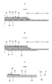
- FIG. 2 is a sectional view taken along line 2-2 of FIG. 1.
- FIG. 3 is a sectional view taken along line 3-3 of FIG. 1.
- FIG. 4A is a sectional view taken along line 4-4 of FIG. 1A and 5B is a sectional view taken along line 5-5 of FIG.
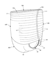
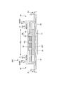
- It is a perspective view (holes omitted) of a pants-type disposable diaper.
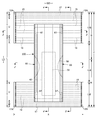
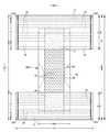
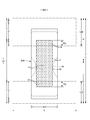
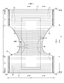
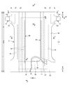
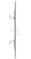
- It is a top view which shows the outer surface of the interior body in a deployment state. It is a top view which shows the outer surface of the interior body of a deployment state with the outline of an exterior body.
- FIG. 9A is a sectional view taken along line 4-4 of FIG. 9, and FIG. 9B is a sectional view taken along line 5-5 of FIG. 9. It is (a) (c) sectional drawing of an adhesion part of a cover nonwoven fabric, (b) (d) top view.
- FIG. 2 is a sectional view taken along line 2-2 of FIG. 1, showing another configuration.
- FIG. 3 is a sectional view taken along line 3-3 of FIG. 1, showing another configuration.
- 14A is a sectional view taken along line 4-4 of FIG. 14 and FIG.
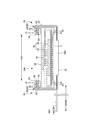
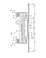
- FIG. 14B is a sectional view taken along line 5-5 of FIG. It is a top view which shows the inner surface of the tape type disposable diaper in a deployment state. It is a top view which shows the outer surface of the tape type disposable diaper in a deployment state.
- FIG. 17 is a sectional view taken along line 6-6 of FIG. 16.
- FIG. 17 is a sectional view taken along line 7-7 of FIG. 16.
- 16A is a sectional view taken along line 8-8 of FIG.
- FIG. 16B is a sectional view taken along line 9-9 of FIG. 16, and FIG.
- It is a principal part enlarged plan view which shows various patterns of the hole of a perforated nonwoven fabric. It is a principal part enlarged plan view which shows various patterns of the hole of a perforated nonwoven fabric. It is a principal part enlarged plan view which shows the chain pattern of the hole of a perforated nonwoven fabric. It is various sectional views of a perforated nonwoven fabric.
- the dotted pattern portion in the cross-sectional view shows an adhesive as a joining means for joining the respective constituent members located on the front side and the back side, and solid, bead, curtain, summit or spiral coating of hot melt adhesive, or pattern coating.
- adhesive Transfer of hot-melt adhesive by letterpress method
- the fixed portion of the elastic member is formed instead of or together with it by coating the outer peripheral surface of the elastic member such as comb gun or Surelap coating. is there.
- hot-melt adhesive there are, for example, EVA-based, adhesive rubber-based (elastomer-based), olefin-based, polyester/polyamide-based adhesives, etc., but they can be used without particular limitation.
- a joining means for joining the respective constituent members it is also possible to use means such as heat sealing or ultrasonic sealing by means of material welding.
- the constituent fibers of the non-woven fabric include, for example, synthetic fibers such as olefins such as polyethylene and polypropylene, polyesters, polyamides (including single-component fibers and composite fibers such as core-sheath), and regenerated rayon and cupra. Fibers, natural fibers such as cotton, etc. can be selected without particular limitation, and these can also be mixed and used. In order to increase the flexibility of the nonwoven fabric, it is preferable that the constituent fibers are crimped fibers.
- Nonwoven fabrics are generally short fiber nonwoven fabrics, long fiber nonwoven fabrics, spunbonded nonwoven fabrics, meltblown nonwoven fabrics, spunlace nonwoven fabrics, thermal bond (air-through) nonwoven fabrics, needle punches, depending on the fiber length, sheet forming method, fiber bonding method, and laminated structure.
- SSS non-woven fabric in which the same or similar non-woven fabric layers are laminated, different non-woven fabric layers are laminated
- SMS non-woven fabric in which melt blown layer is sandwiched between spun bond layers SMMS non-woven fabric, etc.
- any of these non-woven fabrics can be used.
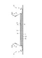
- the pants-type disposable diaper may extend from the front exterior body 12F forming the front body F and the rear exterior body 12B forming the back body B, and from the front exterior body 12F to the rear exterior body 12B via the crotch portion. And an interior body 200 provided inside the exterior bodies 12F and 12B, and both side portions of the front exterior body 12F and both side portions of the rear exterior body 12B are joined to form a side seal portion 12A.
- the openings formed by the front and rear ends of the outer casings 12F and 12B become waist openings WO through which the wearer's torso passes, and the lower edges of the outer casings 12F and 12B and the inner casing 200 on both sides in the width direction of the inner casing 200.
- the portions surrounded by the side edges are the leg openings LO through which the legs pass.
- the inner body 200 is a portion that absorbs and holds excrements such as urine, and the outer bodies 12F and 12B are portions that support the inner body 200 against the wearer's body.
- the symbol Y indicates the total length of the diaper in the unfolded state (the length in the front-rear direction from the edge of the waist opening WO of the front body F to the edge of the waist opening WO of the back body B), and the symbol X indicates the diaper in the unfolded state. Shows the full width of.
- the pants-type disposable diaper of this example forms the waist circumference region T defined as the front-rear direction range (the front-rear direction range from the waist opening WO to the upper end of the leg opening LO) having the side seal portion 12A, and the leg opening LO. It has an intermediate region L defined as a front-back direction range (between the front-back direction region having the side seal portion 12A of the front body F and the front-back direction region having the side seal portion 12A of the back body B).
- the waist circumference region T can be conceptually divided into a “waist portion” W that forms the edge portion of the waist opening and a “waist lower portion” U that is a lower portion thereof.
- the waist opening WO side is closer to the waist opening WO side than the waist opening WO side boundary. If there is no such boundary, the waist portion W side is closer to the waist opening WO than the absorber 56 or the interior body 200.
- These lengths in the front-rear direction differ depending on the size of the product and can be appropriately determined.
- the waist portion W can be 15 to 40 mm and the waist lower portion U can be 65 to 120 mm.
- both side edges of the intermediate region L are bound in a U-shape or a curved shape along the circumference of the wearer's leg, and this is a part where the wearer's leg is put.
- the pants-type disposable diaper in the unfolded state has a substantially hourglass shape as a whole.
- the inner body 200 can be fixed to the outer bodies 12F and 12B by a joining means such as heat sealing or ultrasonic sealing by material welding, or a hot melt adhesive.
- a joining means such as heat sealing or ultrasonic sealing by material welding, or a hot melt adhesive.
- on the back surface of the inner body 200 that is, in this case, on the back surface of the liquid impermeable sheet 11 and the inner surface of the outer body 12F, 12B via the hot melt adhesive applied to the root portion 65 of the side gather 60. It is fixed against.
- the inner and outer joints 201 for fixing the inner body 200 and the outer bodies 12F and 12B can be provided in almost the entire area where they are overlapped with each other. For example, they may be provided in a portion of the inner body 200 excluding both ends in the width direction. it can.
- the inner body 200 can have any shape, but is rectangular in the illustrated form. As shown in FIGS. 3 to 5, the inner body 200 includes the top sheet 30 on the body side, the liquid impermeable sheet 11, and the absorbing element 50 interposed therebetween. Yes, it is the main body that has the absorption function. Reference numeral 40 indicates an intermediate sheet provided between the topsheet 30 and the absorbent element 50 in order to quickly transfer the liquid that has passed through the topsheet 30 to the absorbent element 50, and the reference numeral 60 indicates an interior body. In order to prevent excrement from leaking to both sides of the body 200, side gathers 60 are shown extending from both sides of the inner body 200 so as to come into contact with the wearer's legs.
- the top sheet 30 has a property of permeating a liquid, and examples thereof include a perforated or non-perforated nonwoven fabric and a porous plastic sheet.
- Both sides of the top sheet 30 may be folded back to the back side at the side edges of the absorbent element 50, or may be protruded laterally beyond the side edges of the absorbent element 50 without being folded back.
- the top sheet 30 may be fixed to a member adjacent to the back side by a joining means such as heat sealing or ultrasonic sealing by material welding or a hot melt adhesive for the purpose of preventing the top sheet 30 from being displaced with respect to the back side member. desirable.
- the top sheet 30 is fixed to the surface of the intermediate sheet 40 and the surface of the portion of the packaging sheet 58 located on the front side of the absorbent body 56 by a hot melt adhesive applied to the back surface thereof.
- an intermediate sheet (also referred to as “second sheet”) 40 having a liquid permeation rate higher than that of the top sheet 30 can be provided.
- the intermediate sheet 40 not only quickly transfers the liquid to the absorbent body to enhance the absorption performance of the absorbent body, but also prevents the "return” phenomenon of the absorbed liquid from the absorbent body so that the top sheet 30 is always dried. It can be in the state of having been.
- the intermediate sheet 40 can be omitted.
- the intermediate sheet 40 examples include the same material as the top sheet 30, spunlace nonwoven fabric, spunbond nonwoven fabric, SMS nonwoven fabric, pulp nonwoven fabric, a mixed sheet of pulp and rayon, point bond nonwoven fabric, or crepe paper.
- an air-through nonwoven fabric is preferable because it is bulky.
- the resin used for the core may be polypropylene (PP), but polyester (PET) having high rigidity is preferable.
- Basis weight is preferably 20 ⁇ 80g / m 2, more preferably 25 ⁇ 60g / m 2.
- the raw material fibers of the non-woven fabric preferably have a thickness of 2.0 to 10 dtex.
- eccentric fibers having no core at the center, hollow fibers, or eccentric and hollow fibers as the mixed fibers of all or part of the raw material fibers.
- the intermediate sheet 40 in the illustrated form is arranged in the center shorter than the width of the absorber 56, but may be provided over the entire width.
- the length of the intermediate sheet 40 in the longitudinal direction may be the same as the entire length of the diaper, the length of the absorbent element 50, or may be within a short length range centered on the liquid receiving area.
- the intermediate sheet 40 may be fixed to a member adjacent to the back side by a joining means such as heat sealing or ultrasonic sealing by material welding, or a member adjacent to the back side for the purpose of preventing displacement of the back side member. desirable.
- the intermediate sheet 40 is fixed to the surface of the portion of the packaging sheet 58 located on the front side of the absorbent body 56 by a hot melt adhesive applied to the back surface thereof.
- the material of the liquid impermeable sheet 11 is not particularly limited, but for example, a plastic film made of an olefin resin such as polyethylene or polypropylene, a laminated nonwoven fabric having a plastic film on the surface of the nonwoven fabric, or a plastic film. Examples thereof include a laminated sheet in which nonwoven fabrics and the like are superposed and joined.
- a material that is liquid-impermeable and moisture-permeable which is preferably used from the viewpoint of preventing stuffiness.
- a microporous plastic film obtained by kneading an inorganic filler in an olefin resin such as polyethylene or polypropylene to form a sheet, and then stretching the sheet in a uniaxial or biaxial direction.
- an olefin resin such as polyethylene or polypropylene
- a non-woven fabric using microdenier fiber a method of strengthening leakproofness by reducing the voids of the fiber by applying heat or pressure, coating a super absorbent resin or hydrophobic resin, or a water repellent agent
- a liquid-impermeable sheet without using a plastic film can also be used as the liquid-impermeable sheet 11.
- the liquid-impermeable sheet 11 has a width that fits on the back side of the absorbent element 50 as shown in the figure, and in order to improve the leakproof property, the liquid-impermeable sheet 11 is wrapped around both sides of the absorbent element 50 so that the side surface of the top sheet 30 of the absorbent element 50 is covered. It can also extend to both sides. It is appropriate that the width of the extending portion is about 5 to 20 mm on each of the left and right sides.
- the side gathers 60 extend along the both sides of the inner body 200 in the front-rear direction LD and are provided to contact the wearer's legs and prevent lateral leakage, and are generally three-dimensional. This includes what is called gathers and what is called flat gathers.
- the side gathers 60 of the first structure shown in FIGS. 3 and 4 are so-called three-dimensional gathers, and stand upright from the sides of the interior body 200 to the front side.
- the base side portion is erected obliquely toward the center side in the width direction
- the tip side portion from the intermediate portion is erected obliquely toward the width direction outer side.
- the present invention is not limited to this, and can be appropriately changed such as a form in which it stands up on the center side in the width direction as a whole.
- a strip-shaped gathered nonwoven fabric 62 having a length equal to the length of the interior body 200 in the front-rear direction is folded back in the width direction WD at the end portion.
- a plurality of elongated gather elastic members 63 are fixed along the longitudinal direction between the folded-back portions and the sheets in the vicinity thereof while being folded in one and spaced at intervals in the width direction WD. ..
- a base end portion (an end portion on the opposite side of the sheet folding portion in the width direction WD) of the side gather 60 located on the side opposite to the tip end portion is located on a side portion on the back side of the liquid impermeable sheet 11 in the interior body 200.
- the root portion 65 is fixed, and the portion other than the root portion 65 is a main body portion 66 (a portion on the folded-back portion side) extending from the root portion 65.
- the main body portion 66 is composed of a root side portion facing the center side in the width direction and a tip side portion folded back outward in the width direction from the tip of the root side portion. This form is the surface contact type side gather 60, but a line contact type side gather 60 that is not folded back outward in the width direction can also be adopted.
- both ends of the main body portion 66 in the front-rear direction are in a laid-down state to be the laid-down portions 67 fixed to the side surface of the top sheet 30, while the intermediate portion in the front-rear direction located between them is not. It is a fixed free portion 68, and the gather elastic member 63 along the front-rear direction LD is fixed to the free portion 68 in an extended state.
- the gathered non-woven fabric 62 spun bond non-woven fabric (SS, SSS, etc.), SMS non-woven fabric (SMS, SSMMS, etc.), melt blown non-woven fabric, etc., which is flexible and has excellent uniformity and concealing property, is water-repellent with silicone as necessary
- the treated product can be preferably used, and the fiber areal weight is preferably about 10 to 30 g/m 2 .
- the gather elastic member 63 thread rubber or the like can be used. When using spandex thread rubber, the thickness is preferably 470 to 1240 dtex, and more preferably 620 to 940 dtex.
- the elongation rate when fixed is preferably 150 to 350%, more preferably 200 to 300%.
- a waterproof film 64 may be interposed between the gathered nonwoven fabrics 62 folded in two, and in this case, the gathered nonwoven fabrics 62 may be partially omitted in the portion where the waterproof film 64 exists.
- the gathered nonwoven fabrics 62 may be partially omitted in the portion where the waterproof film 64 exists.
- the number of gather elastic members 63 provided in the free portion of the side gathers 60 is preferably 2 to 6, and more preferably 3 to 5. It is suitable that the arrangement interval 60d is 3 to 10 mm. According to this structure, the surface of the gather elastic member 63 can easily come into contact with the skin.
- the gather elastic member 63 may be arranged not only on the tip side but also on the base side.
- a hot melt adhesive and a heat seal or a super-sealing agent by various coating methods are used for bonding the inner layer and the outer layer of the gather nonwoven fabric 62 and fixing the gather elastic member 63 sandwiched therebetween.
- At least one of fixing means by material welding such as a sonic seal can be used. Since the flexibility is impaired when the entire surfaces of the inner layer and the outer layer of the gathered nonwoven fabric 62 are bonded, it is preferable that the portions other than the bonded portion of the gathered elastic member 63 are not bonded or weakly bonded.
- a hot melt adhesive is applied only to the outer peripheral surface of the gather elastic member 63 by an application means such as a comb gun or a Surelap nozzle, and is sandwiched between the inner layer and the outer layer of the gather nonwoven fabric 62, so that the gather elastic member 63.
- the gather elastic member 63 is fixed to the inner layer and the outer layer of the gather nonwoven fabric 62 and the gather nonwoven fabric 62 is fixed between the inner layer and the outer layer only with the hot melt adhesive applied to the outer peripheral surface of the gather nonwoven fabric 62.
- a hot melt adhesive and heat seal by various coating methods are used. It is possible to use at least one of means such as ultrasonic welding and material welding. In the illustrated form, slot application of a hot melt adhesive is used for fixing the waterproof film 64. Further, the fixing of the collapsed portion 67 in the illustrated form is performed by combining means using a hot melt adhesive and material welding, but it is also possible to fix these by only one of the means.
- the base sheet 65 of the side gathers 60 may be fixed to the top sheet 30, the liquid-impermeable sheet 11, the absorbent element 50, and other appropriate members in the interior body 200.
- the contracting force of the gather elastic member 63 acts so as to bring both end portions in the front-rear direction closer to each other, but both end portions in the front-rear direction of the main body portion 66 do not stand up. While they are fixed as described above, they are non-fixed free portions, so that only the free portions stand up to abut the body side as shown in FIG. In particular, when the root portion 65 is located on the back side of the inner body 200, the side gathers 60 stand up to open outward in the width direction at the crotch portion and in the vicinity thereof. It comes into contact with each other, and the fit is improved.
- the size of the side gathers 60 of the first structure can be set as appropriate, but in the case of an infant paper diaper, as shown in FIG. 3, for example, the standing height of the side gathers 60 (the main body portion 66 in the unfolded state).
- the length W6 in the width direction is preferably 15 to 60 mm, particularly preferably 20 to 40 mm.
- the separation distance W3 between the innermost folds when the side gathers 60 are folded flat so that the side gathers 60 are parallel to the surface of the top sheet 30 is preferably 60 to 190 mm, particularly preferably 70 to 140 mm.
- the side gathers 60 of the first structure include only the three-dimensional gathers, but may include both the three-dimensional gathers and the flat gathers, or may include only the flat gathers.
- 12 and 13 show a second structure of side gathers 60 that includes both solid and planar gathers.
- Each side gather 60 has a first portion 61 (a flat gather portion) protruding laterally from the inner body 200 from a root portion 65 fixed to a side portion on the back side of the liquid impermeable sheet 11 in the inner body 200. And a second portion 69 (three-dimensional gather portion) projecting from the root portion 65 fixed to both sides of the top sheet 30 in the interior body 200 to the front side of the interior body 200.
- a belt-shaped gathered nonwoven fabric 62 having a length equal to the length of the interior body 200 in the front-rear direction extends laterally from the root portion 65 and is folded back to the front side at the tip of the first portion 61.
- the portion folded back to the front side reaches the second portion 69 through the first portion 61, and is folded back at the tip of the second portion 69.
- Opposing portions of the gathered non-woven fabric 62 that are folded are joined together by a hot melt adhesive or the like.
- both end portions in the front-rear direction of the second portion 69 are the fall portions 67 fixed to the side surface of the topsheet 30 in the fall state, while the middle portion in the front-rear direction located between them. Is an unfixed free portion 68.
- At least the middle portion of the first portion 61 in the front-rear direction and the free portion 68 of the second portion 69 have one gather elastic member 63 along the front-rear direction LD or a plurality of gather elastic members 63 extending at intervals in the width direction WD.
- the free portion 68 of the second portion 69 contracts in the front-rear direction LD by the contracting force and becomes a three-dimensional gather in contact with the periphery of the leg, and the first portion 61 contracts in the front-rear direction LD. It becomes a flat gather that contacts the legs.
- the material of the gathered nonwoven fabric 62, the material of the gathered elastic member 63, and the like are the same as those of the first structure, and therefore description thereof is omitted.
- the absorbent element 50 has an absorbent body 56 and a wrapping sheet 58 that wraps the entire absorbent body 56.
- the packaging sheet 58 may be omitted.
- the absorber 56 can be formed of a fiber aggregate. This fiber assembly is obtained by laminating short fibers such as cotton-like pulp and synthetic fibers, and filament aggregates obtained by opening tows (fiber bundles) of synthetic fibers such as cellulose acetate as needed. Can also be used.
- the fiber basis weight may be, for example, about 100 to 300 g/m 2 when laminating cotton-like pulp or short fibers, and about 30 to 120 g/m 2 for a filament aggregate. You can
- the absorber 56 may have a rectangular shape, but as shown in FIGS. 1 and 7, the constricted portion 56N located at the front end portion, the rear end portion, and between them and having a narrower width than the front end portion and the rear end portion. It is preferable to form the hourglass shape having “” because the fit of the absorber 56 itself and the side gathers 60 around the legs is improved.
- the absorber 56 may contain superabsorbent polymer particles in a part or all thereof.
- Superabsorbent polymer particles include "powder” in addition to “particles”.
- the superabsorbent polymer particles those used in this type of disposable diaper can be used as they are.
- tissue paper especially crepe paper, non-woven fabric, poly-laminated non-woven fabric, a sheet with small holes, or the like can be used. However, it is desirable that the sheet does not allow the superabsorbent polymer particles to escape.
- a non-woven fabric is used instead of the crepe paper, a hydrophilic SMS non-woven fabric (SMS, SSMMS, etc.) is particularly suitable, and the material thereof can be polypropylene, polyethylene/polypropylene composite material or the like.
- the basis weight is preferably 5 to 40 g/m 2 , particularly 10 to 30 g/m 2 .
- the outer casings 12F and 12B include a front outer casing 12F that is a portion that forms the front body F and a rear outer casing 12B that is a portion that forms the rear body B.
- the front outer casing 12F and the rear outer casing 12B Is not continuous on the crotch side and is separated in the front-rear direction LD (two-part exterior type).
- the separation distance 12d can be set to about 150 to 250 mm, for example.
- the exterior body 12 may be an integral one that is continuous through the crotch from the front body F to the back body B (exterior integrated type).
- the outer casings 12F and 12B have a waist region that is a front-rear range corresponding to the waist region T. Further, in the present embodiment, the front exterior body 12F does not have a portion corresponding to the intermediate region L, but the rear exterior body 12B has a buttock cover portion C extending from the waist circumference region T to the intermediate region L side. doing. Although not shown, the front exterior body 12F is also provided with a groin cover portion extending from the waist circumference region T to the intermediate region L side, or a groin cover portion is provided but no buttocks cover portion is provided, or the front exterior body 12F and It is not necessary to provide a portion corresponding to the intermediate region L on both of the rear exterior body 12B.
- the lower edge of the buttocks cover portion C is formed in a linear shape along the width direction WD like the lower edge of the front exterior body 12F, but is located on the waist opening side toward the outer side in the width direction. It can also be a curved line.
- the outer casings 12F and 12B are formed by joining the outer sheet layer 12S and the inner sheet layer 12H by a joining means such as a hot melt adhesive or welding.
- the sheet material forming the outer sheet layer 12S and the sheet material forming the inner sheet layer 12H may be a single sheet material common as in the form shown in FIG. 5, or may be individual sheet materials. That is, in the former case, the inner sheet layer 12H and the outer sheet layer 12S are formed by the inner portion and the outer portion of one sheet material folded at the edge of the waist opening WO (may be the edge on the crotch side). To be done.
- the former form has an advantage that the number of materials of the sheet material is small, and the latter form has an advantage that the inner sheet layer 12H and the outer sheet layer 12S are less likely to be misaligned.
- the sheet material used for the outer sheet layer 12S and the inner sheet layer 12H can be used without particular limitation, but a non-woven fabric is preferable, and when a non-woven fabric is used, its basis weight is preferably about 10 to 30 g/m 2 .
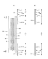
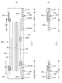
- elongated elastic members 15 to 19 such as rubber thread are provided between the outer sheet layer 12S and the inner sheet layer 12H in order to improve the fit around the wearer's waist.
- An elastic region that elastically expands and contracts in the width direction WD with the expansion and contraction is formed.
- the outer sheet layer 12S and the inner sheet layer 12H contract in accordance with the contraction of the elastic member in a natural length state, and wrinkles or folds are formed.
- the layer 12S and the inner sheet layer 12H can be stretched to a predetermined stretching rate at which they can be stretched without wrinkles.
- synthetic rubber or natural rubber may be used.
- a hot melt adhesive and heat seal or ultrasonic seal by various coating methods are used. It is possible to use at least one of fixing means by material welding such as. If the entire outer casings 12F and 12B are firmly fixed, the flexibility is impaired. Therefore, it is preferable that the elastic members 15 to 19 are not bonded or weakly bonded except the bonded portions.
- the hot melt adhesive is applied only to the outer peripheral surfaces of the elastic members 15 to 19 by applying means such as a comb gun or a Surelap nozzle, and the hot melt adhesive is sandwiched between the sheet layers 12S and 12H.
- the structure is such that the elastic members 15 to 19 are fixed to both the sheet layers 12S and 12H and the sheet layers 12S and 12H are fixed to each other only by the hot melt adhesive applied to the outer peripheral surface of the sheet.
- the elastic members 15 to 19 can be fixed to the outer sheet layer 12S and the inner sheet layer 12H only at both ends in the stretch direction in the stretch region.
- a plurality of waist elastic members 17 are vertically arranged so as to be continuous over the entire width direction WD. It is mounted at intervals. Further, one or more of the waist elastic members 17 disposed in the region adjacent to the lower waist portion U may overlap the interior body 200, or may extend in the width direction where the interior body 200 overlaps. They may be provided on both sides in the width direction except the central portion.
- the waist elastic member 17 has a thickness of 155-1880 dtex, particularly about 470-1240 dtex (in the case of synthetic rubber. In the case of natural rubber, the cross-sectional area is 0.05-1.5 mm 2 , particularly 0.1-1.
- the waist portion W does not need to use the waist portion elastic members 17 having the same thickness in all of the front-rear direction LD or to have the same extension rate. The thickness and the extension rate may be different.
- a plurality of lower waist elastic members 15 and 19 made of elongated elastic members are vertically spaced. It is installed empty.
- the waist lower elastic members 15 and 19 have a thickness of 155-1880 dtex, especially about 470-1240 dtex (in the case of synthetic rubber. In the case of natural rubber, a cross-sectional area of 0.05-1.5 mm 2 , particularly 0.1-). It is preferable to provide about 5 to 30 thread rubbers (about 1.0 mm 2 ) at intervals of 1 to 15 mm, particularly 3 to 8 mm, and the elongation rate of the lower waist portion U in the width direction WD is 200 to 350%. It is particularly preferably about 240 to 300%.
- a plurality of cover portion elastic members 16 made of elongated elastic members are attached at intervals in the vertical direction. Has been.
- the cover elastic member 16 has a thickness of 155 to 1880 dtex, particularly about 470 to 1240 dtex (in the case of synthetic rubber.
- the cross-sectional area is 0.05 to 1.5 mm 2 , particularly 0.1 to 1.0 mm). It is preferable to provide about 2 to 10 thread rubbers (about 2 ) at an interval of 5 to 40 mm, especially 5 to 20 mm, and the elongation rate of the cover portion in the width direction WD is 150 to 300%, particularly 180 to 260. % Is preferred.
- a cover elastic member can be provided in the same manner.
- an intermediate portion in the width direction including a part or all of the portion overlapping the absorber 56 in the width direction WD is the non-stretchable area A1.
- Both sides in the width direction are stretchable regions A2.
- the waist portion W is preferably formed as the stretchable region A2 over the entire width direction WD, but like the waist lower portion U, a non-stretchable region A1 may be provided in the middle in the width direction.
- the stretchable area A2 and the non-stretchable area A1 supply the elastic members 15 to 17 and 19 between the inner sheet layer 12H and the outer sheet layer 12S so that the elastic members 15, 16 and 19 are at least stretched in the stretchable area A2.
- the elastic members 15, 16 and 19 are fixed at both ends in the direction via the hot melt adhesive and not fixed in the non-stretchable area A1 and the elastic members 15, 16 and 19 in the middle in the width direction are fixed in the non-stretchable area A1.
- the elastic members 15, 16 and 19 are cut by pressurizing and heating at a place, or almost all of the elastic members 15, 16 and 19 are finely cut by pressing and heating, and the elastic property is left in the elastic region A2 while the elastic property is maintained in the non-elastic region A1. Can be built by killing.
- the uncut elastic member 15, 16 and 19 in the stretchable region A2 is continuously contracted to the natural length as the unnecessary elastic member 18, and It remains between the outer sheet layer 12S and the inner sheet layer 12H, and in the latter case, although not shown, the cutting residual portions continuous from the elastic members 15, 16, 19 of the stretchable region A2 and the elastic members 15 of both stretchable regions A2.
- 16 and 19 that are not continuous with the elastic member remain as an unnecessary elastic member between the outer sheet layer 12S and the inner sheet layer 12H in a state where they are independently shrunk to the natural length.
- the inner body 200 is exposed between the front outer body 12F and the rear outer body 12B, so that the liquid impermeable sheet 11 is not exposed on the back surface of the inner body 200.
- a cover nonwoven fabric 20 covering the back surface of the inner body 200 is provided between the front outer body 12F and the inner body 200 and between the rear outer body 12B and the inner body 200.
- the outer sheet layer 12S of the exterior body 12 is a non-woven fabric
- the outer sheet layer 12S continues from the front body F to the back body B through the crotch
- the cover nonwoven fabric 20 covers the liquid impermeable sheet 11.
- the basis weight and thickness of the cover non-woven fabric 20 can be appropriately determined, but normally, the basis weight is preferably 15 to 30 g/m 2 and the thickness is preferably 0.2 to 1.2 mm.
- the front-rear direction range of the cover nonwoven fabric 20 is not particularly limited as long as it has a portion that overlaps the front exterior body 12F and the rear exterior body 12B, and as shown in FIGS. 2, 5, 7, 9, and 10. In addition, it may extend in the front-rear direction LD over the entire front body to the rear end of the inner body 200, and as shown in FIG. It may extend in the front-rear direction LD from the position to the intermediate position in the front-rear direction in the region where the rear exterior body 12B and the inner body 200 overlap.
- the front-rear length 20y of the overlapping portion of the cover nonwoven fabric 20 and the front exterior body 12F, and the front-rear length 20y of the overlapping portion of the cover nonwoven fabric 20 and the rear exterior body 12B can be appropriately determined. In the normal case, it can be about 5 to 40 mm.
- the width direction range of the cover non-woven fabric 20 is a range in which the exposed back surface of the liquid impermeable sheet 11 can be hidden. Therefore, in the illustrated embodiment, since the liquid impermeable sheet 11 is exposed between the base ends of the left and right side gathers 60, at least the back side of the base end portions of the one side gathers 60 to the other side gathers 60.
- the cover non-woven fabric 20 is provided so as to cover the widthwise range up to the back side of the base end portion of the. As a result, the liquid impermeable sheet 11 can be covered with the cover nonwoven fabric 20 and the gather nonwoven fabric 62 of the side gathers 60, and the holes 14 at both widthwise end portions of the cover nonwoven fabric 20 have the gather nonwoven fabric 62 when viewed from the outside.
- the cover nonwoven fabric is also possible. It is possible to hide the liquid impermeable sheet 11 with the gathered nonwoven fabric 62 and the gathered nonwoven fabric 62. In that case, when the total light transmittance of the gathered nonwoven fabric 62 is 60 to 90%, the gathered nonwoven fabric 62 covers the cover nonwoven fabric 20.
- the tape-type disposable diaper includes an absorbent body 56 extending from the ventral side to the dorsal side, a liquid-permeable top sheet 30 that covers the front side of the absorbent body 56, and a liquid-impermeable sheet 11 that covers the back side of the absorbent body 56.
- the end flap portion EF which is a portion that extends to the front side and the rear side of the absorbent body 56 and does not have the absorbent body 56, and a side of the side edge of the absorbent body 56.
- the back surface of the liquid impermeable sheet 11 is covered with a cover nonwoven fabric 20.
- the basis weight and thickness of the cover non-woven fabric 20 can be appropriately determined, but normally, the basis weight is preferably 15 to 30 g/m 2 and the thickness is preferably 0.2 to 1.2 mm.
- the cover non-woven fabric 20 extends to the peripheral edge of the diaper, the liquid impermeable sheet 11 extends to the front and rear edges of the diaper in the front-rear direction, and the side edges of the absorber and the outer sheet in the width direction.
- the cover nonwoven fabric 20 may be a part in the front-rear direction, a part in the width direction, or both as necessary.
- the cover nonwoven fabric 20 may not be provided for that portion.
- the top sheet 30 and the liquid impermeable sheet 11 are rectangular in the illustrated example, have dimensions slightly larger in the front-rear direction and the width direction than the absorbent element 50, and protrude from the side edge of the absorbent element 50 in the top sheet 30.
- the peripheral edge portion and the peripheral edge portion protruding from the side edge of the absorbent element 50 in the liquid impermeable sheet 11 are joined by a hot melt adhesive or the like.
- the absorbent body 56 can be interposed between the top sheet and the liquid impermeable sheet as an absorbent element packaged by a wrapping sheet, and the intermediate body is not provided between the top sheet and the absorbent element.
- a seat 40 can be provided.
- the intermediate sheet 40 in the illustrated form is centrally located shorter than the width of the absorbent element 50, but may be provided over the entire width.
- the length of the intermediate sheet 40 in the longitudinal direction may be the same as the entire length of the diaper, the length of the absorbent element 50, or may be within a short length range centered on the liquid receiving area.
- a discoloring indicator that comes into contact with the liquid content of the excrement can be provided.
- Each side gather 60 has a first portion 61 (flat gather portion) provided on each side flap portion SF and a second portion 69 (three-dimensional gather portion) protruding on both side portions of the top sheet 30. It includes. More specifically, a belt-shaped gathered nonwoven fabric 62 having a length equal to the total length Y of the diaper extends from the first portion 61 to the second portion 69, and the gathered nonwoven fabric 62 covers the gathered nonwoven fabric 62 in the first portion 61.
- one gather elastic member 63 along the front-rear direction LD is fixed in a stretched state with one or at intervals in the width direction WD,
- the contraction force contracts the first portion 61 in the front-rear direction LD to form a flat gather that contacts the legs.
- the gathered nonwoven fabric 62 has an extending portion extending from the first portion 61 to the widthwise center of the WD with the first portion 61 as a root portion, and at least this extending portion is folded back at the tip to form a two-layer structure. Has been done.
- Both ends of the extending portion in the front-rear direction LD are laid-down portions 67 fixed to the top sheet 30, while an intermediate portion in the front-rear direction LD located between them is an unfixed free portion 68.
- One or a plurality of gather elastic members 63 along the front-rear direction LD are fixed to the free portion 68 in a stretched state at intervals in the width direction WD, and the contraction force of the gather elastic members 63 secures the free portion 68 of the second portion 69. Becomes a three-dimensional gather that contracts in the front-back direction LD and contacts the legs.
- the fastening tape 13 in the illustrated form is a tape base 13B fixed to the side of the diaper, and a sheet base material forming the tape main body 13B protruding from the tape mounting portion 13C, and the tape main body 13B in the sheet base. It has a locking portion 13A for the abdominal side, which is provided in the middle portion in the width direction of the above, and the front end side of this locking portion 13A is the knob portion.
- the tape attachment portion 13C of the fastening tape 13 is sandwiched between the gather nonwoven fabric 62 forming the inner layer and the cover nonwoven fabric 20 forming the outer layer in the side flap portion, and is adhered to both the nonwoven fabrics 62, 20 by a hot melt adhesive. ..
- the locking portion 13A is joined to the inner surface of the tape body portion 13B with an adhesive.
- a hook material (male material) of a mechanical fastener (face fastener) is suitable.
- the hook member has a large number of engaging protrusions on its outer surface side.
- the shape of the engaging projections is (A) L-shaped, (B) J-shaped, (C) mushroom-shaped, (D) T-shaped, (E) double J-shaped (J-shaped However, any shape may be used.
- an adhesive material layer can be provided as a locking portion of the fastening tape 13.
- a non-woven fabric a plastic film, a poly-laminated non-woven fabric, paper or a composite material of these can be used.
- the fastening tape 13 When attaching the diaper, the fastening tape 13 is locked in place on the outer surface of the abdomen while the back side flaps SF are stacked on the outside of the abdominal side flaps SF.
- the position and size of the fastening portion of the fastening tape 13 can be arbitrarily determined.
- the target sheet 24 has a target for facilitating the locking at the locking position of the fastening tape 13 on the abdominal side.
- the target sheet 24 is of a film type having a film layer and an engagement layer provided on the entire outer surface thereof to which the hook of the locking portion 13A is detachably engaged. What can be used suitably.
- the engagement layer in this case, in addition to the form in which a net-like body woven with threads and having a loop is attached on the film layer, a nonwoven fabric layer of thermoplastic resin is intermittently ultrasonically sealed. A form in which fibers of a non-woven fabric are looped on a film layer is known, but any of them can be preferably used.
- a filmless type target tape having no film layer which is obtained by embossing a thermoplastic resin nonwoven fabric.
- the fastening tape 13 is joined by the loops or hooks of the fastening tape 13 being caught in the loop.
- the locking portion 13A is an adhesive material layer
- a sheet base material made of a plastic film having a smooth surface which is rich in adhesiveness and having a release treatment applied thereto can be used.
- the fastening portion of the fastening tape 13 on the ventral side is made of a non-woven fabric
- the cover non-woven fabric 20 shown in the figure is made of a non-woven fabric and the fastening portion 13A of the fastening tape 13 is a hook material
- the target sheet 24 may be omitted, and the hook material may be entwined with the nonwoven fabric of the cover nonwoven fabric 20 and locked.
- the target sheet 24 may be provided between the cover nonwoven fabric 20 and the liquid impermeable sheet 11.
- the cover nonwoven fabric 20 covers the back side of the liquid-impermeable sheet 11 and forms the outer surface of the product in at least a part of the portion covering the liquid-impermeable sheet 11, it is desirable to improve the air permeability. Therefore, the cover non-woven fabric 20 is preferably a perforated non-woven fabric in which a large number of holes 14 penetrating the front and back are provided at intervals as in the illustrated example.
- the top sheet 30 may be a perforated nonwoven fabric or the gathered non-woven fabric 62 may be a perforated nonwoven fabric in order to improve liquid permeability.
- the cover non-woven fabric 20 be provided with the holes 14 throughout as in the examples shown in FIGS. 7 and 8.
- the cover non-woven fabric 20 has a region where there is no hole 14, such as forming the hole 14 only in an intermediate region in the front-rear direction that does not have the elastic members 15 to 18.
- the holes 14 can be formed in the entire cover nonwoven fabric 20 in the front-rear direction and the width direction.
- the region where the holes 14 are formed is from the portion of the cover nonwoven fabric 20 overlapping the front outer casing 12F to the rear outer casing 12B. It is desirable to continue to the overlapping part.
- each hole 14 has a long hole shape as shown in FIGS. 21(b) and 22(b), and also has a perfect circle shape as shown in FIGS. 21(e), (f) and 22(e).
- the shape may be an arbitrary shape such as an ellipse, a triangle, a rectangle, a polygon such as a rhombus, a star shape, or a cloud shape as shown in FIGS.
- holes 14 having different shapes may be mixed.
- the dimensions of the individual holes 14 are not particularly limited, but the dimension in the CD direction (dimension of the longest portion) 14L is preferably 0.6 to 5.0 mm, particularly preferably 0.7 to 2.0 mm, and the dimension in the MD direction is preferably.
- the dimension (the dimension of the longest portion) 14W is preferably 0.6 to 5.0 mm, particularly preferably 0.6 to 1.2 mm.
- the dimension in the MD direction It is preferable that (the dimension of the longest part) is 1.2 to 2.5 times the dimension (the dimension of the longest part) in the CD direction orthogonal to this.
- the longitudinal direction of the holes 14 is preferably the MD direction of the nonwoven fabric, but may be the CD direction or the oblique direction inclined with respect to these.
- the MD direction of the nonwoven fabric is equal to the width direction WD in the outer body 12 of the pants-type disposable diaper and equal to the front-rear direction LD in the inner body 200 of the pants-type disposable diaper, except for the fastening tape in the tape-type disposable diaper.
- the part LD is in the front-back direction LD.
- each hole 14 may be appropriately determined, but the area is preferably about 0.1 to 2.7 mm 2 (particularly 0.1 to 1.0 mm 2 ), and the area ratio is 1. It is preferably about 0 to 15.0% (particularly 5.0 to 10.0%).
- the planar arrangement of the holes 14 can be appropriately determined and may be irregular, or may be a pattern or a character, but a regularly repeated planar arrangement is preferable.
- FIGS. 21A, 21 ⁇ /b>C, and 21 ⁇ /b>D in the planar array of all holes 14, rows of holes 14 linearly arranged at a predetermined interval in the CD direction have a predetermined interval in the MD direction. It is preferable that it is in a matrix form that repeats at intervals.
- the distance 14x between the holes 14 in the MD direction is shorter than the distance 14y between the holes 14 in the CD direction, and as shown in FIG.
- the distance 14x in the MD direction is substantially equal to the distance 14y in the CD direction between the holes 14, or, as shown in FIG. 21D, the distance 14x in the MD direction between the holes 14 is greater than the distance 14y in the CD direction between the holes 14.
- the rows 91 and 92 of holes linearly arranged at a predetermined interval in the CD direction are spaced in the MD direction and are displaced in the CD direction. It can be arranged side by side.
- the example shown in FIG. 21B is a so-called staggered (hexagonal lattice) arrangement in which the holes 14 are arranged alternately in the adjacent hole rows 91 and 92. Further, as shown in FIG.
- the holes 14 are arranged in a wavy line having a center line along the direction orthogonal to the MD direction. Also, the row of holes 14 arranged at intervals in the direction orthogonal to the MD direction is included in the row arranged at intervals in the MD direction.
- the size and shape of the holes 14 in the first hole array 91 and the size and shape of the holes 14 in the second hole array 92 may be the same, but it is more preferable that at least one of them is different.
- the CD-direction spacing 14y and the MD-direction spacing 14x of the holes 14 may be constant or may change. These can be appropriately determined, but in consideration of air permeability, it is desirable that the distance 14y in the CD direction between the holes 14 is 0.9 to 8.0 mm, and particularly 1.0 to 3.0 mm. It is desirable that the MD direction interval 14x is within the range of 2.0 to 10 mm, and particularly 3.0 to 5.0 mm. In particular, rows of holes 14 aligned in the CD direction with a CD direction interval 14y narrower than the CD direction size 14L of the holes 14 repeat at predetermined intervals in the MD direction, and the MD direction interval 14x is greater than the CD direction size 14L of the holes 14.
- a large width (more preferably 3 times or more the dimension 14W of the hole 14 in the MD direction) makes the improvement of air permeability remarkably, and does not impair the softness and bulkiness, and is important in the MD direction during manufacturing. Is preferable because the decrease in tensile strength is less. Particularly in this case, it is preferable that the shape of the hole 14 is elongated in the CD direction.
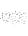
- the planar arrangement of the holes 14 is such that a group 90 of holes 14 arranged so as to have a single wavy shape continuing in the MD direction is spaced in the CD direction.
- the groups 90 of the holes 14 that are arranged at intervals so as to form a chain that continues in the MD direction may be arranged at intervals in the CD direction.
- the group 90 of the holes 14 arranged in a chain shape is not particularly limited as long as the portions where the holes 14 are arranged in an annular shape repeat at intervals in the MD direction. For example, as shown in FIG.
- the groups 90 of holes 14 arranged so as to form a double wavy shape may be arranged at intervals in the CD direction, or may have a chain shape as shown in FIG.
- “the groups 90 of holes 14 are arranged at intervals in the CD direction” means that there is a non-hole portion 93 that is straight and continuous in the MD direction between the groups 90 of holes 14 that are adjacent in the CD direction. Means to have.
- the array shape of the holes 14 in the group 90 can be appropriately determined as long as it is in the above-mentioned wavy shape.
- the peaks and valleys of an arc curve as shown in FIG. 22(a) are repeatedly wavy, or as shown in FIG. 22(b).
- 22D a rectangular wave as shown in FIG. 22D, a sinusoidal curve like the group 90 of the holes 14 in the middle of FIG. At least one of them may have a regular or irregularly changing shape, or another irregular shape.
- the distance 14x in the MD direction between the holes 14 in the group 90 of holes 14 may be constant or may change, and can be appropriately determined. Considering the improvement of the air permeability by the holes 14, it is desirable that the thickness is in the range of 2.0 to 10 mm, particularly 3.0 to 5.0 mm.
- the spacing 14y in the CD direction of the holes 14 in the row 94 of each hole 14 may change, or in the example shown in FIGS. 22A and 22B. May be constant.
- the distance 14y in the CD direction between the holes 14 in the row 94 of holes 14 is preferably in the range of 0.9 to 8.0 mm, particularly 1.0 to 3.0 mm.
- the CD-direction spacing 14y of the holes 14 in the row 94 of holes 14 may be longer or the same as the MD-direction spacing 14x of the holes 14 in the group 90 of holes 14 (2 to It is desirable to be about 5 times).
- the cross-sectional shape of the hole 14 is not particularly limited.
- the hole 14 is a punched type hole whose peripheral edge is formed by the cut ends of the fibers, there is almost no cut end of the fiber at the peripheral edge of the hole 14, and the pin is inserted between the fibers and expanded. It may be a non-punching type hole (having a high fiber density at the edge) formed by the above.
- the punched-type hole has a hole 14 whose diameter becomes smaller toward the middle in the thickness direction, but which is not shown but becomes smaller toward one side in the thickness direction. May be.
- the non-punching type hole 14 is such that the diameter of the hole 14 decreases from the pin insertion side to the opposite side. This includes not only those in which the diameter of the holes 14 continues to decrease throughout the thickness direction of the nonwoven fabric layer, but also those in which the decrease in the diameter of the holes 14 almost disappears in the middle of the thickness direction.
- a fiber is extruded to the side opposite to the pin insertion side at the edge of the hole 14 on the side opposite to the pin insertion side.
- the portion (burr) 14e is formed and the protruding portion 14e is not formed on the pin insertion side, and as shown in FIG.
- the fiber is pin-inserted at the edge of the hole 14 on the side opposite to the pin insertion side.
- the protrusion 14e extruded on the side opposite to the side is formed, and the pin insertion side includes the protrusion 14e formed by extruding the fiber on the pin insertion side.
- the protrusion height 14h of the protrusion 14e is substantially uniform as shown in FIG. 24(a), and the protrusion 14e is as shown in FIG. 24(c). It includes a facing portion having the highest protruding height 14i and a facing portion facing in a direction orthogonal to the protruding height 14i and having a lowest protruding height 14j.
- the protrusions 14e be cylindrical in a continuous manner in the circumferential direction of the hole, but the protrusions 14e of some or all of the holes 14 are formed only in a portion of the hole 14 in the circumferential direction. Good.
- the projecting heights 14h, 14i, 14j are preferably about 0.2 to 1.2 mm.
- the highest protrusion height 14i of the protrusion 14e is preferably about 1.1 to 1.4 times the lowest protrusion height 14j.
- the protrusion height of the protrusion 14e may change in the circumferential direction of the hole 14.
- a protruding portion (burr) 14e is formed in which the protruding height 14i of the facing portion of the hole 14 in the longitudinal direction is higher than the protruding height 14j of the facing portion in the direction orthogonal to the longitudinal direction.
- the protrusion 14e of the hole 14 may have a fiber density lower than that of the surrounding portion, but it is preferable that the fiber density is the same or higher.
- the perforated nonwoven fabric has a fineness of 0.1 to 5.0 dtex (more preferably 1.0 to 3.0 dtex), a basis weight of 15 to 20 g/m 2 (more preferably 15 to 18 g/m 2 ), and a thickness of 0.
- a long fiber non-woven fabric of 3 to 0.8 mm (more preferably 0.3 to 0.6 mm) when the hole 14 is formed by inserting the pin, the protrusion 14e formed at the edge of the hole 14 becomes low. .. More specifically, in the case of the long-fiber non-woven fabric in the above specific range, it is difficult for the fibers to be extruded in the thickness direction when forming the pin insertion hole.
- the fibers to which force is applied by inserting the pins are continuous (continuous fibers) while being entangled throughout the nonwoven fabric, and the movement of fibers at the part to which force is applied by inserting the pins is suppressed by the part connected to the outside. Is. Furthermore, since the long-fiber non-woven fabric in the above-mentioned specific range basically has an appropriately low fiber density, the movement of the fibers in the direction orthogonal to the thickness direction is relatively easy. As a result, when the pin is inserted into the long-fiber non-woven fabric in the specific range described above and the hole 14 having the size in the specific range is formed, the fibers near the pin radiate around the insertion direction of the pin when the pin is inserted.
- the protrusion 14e Since the protrusion 14e is formed while being pushed in the direction, the protrusion 14e is formed, but its height becomes low. Therefore, a high density portion having a higher fiber density than the surroundings is formed at the edge of the hole 14.
- the high density portion has an advantage that the shadow between the periphery of the hole and the hole becomes stronger and the visibility of the hole is improved.
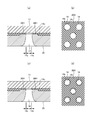
- the perforated nonwoven fabric has a supporting surface opposite to the exposed surface exposed to the outside, and another sheet facing the supporting surface (when the perforated nonwoven fabric is the cover sheet 20, the liquid impermeable sheet 11 is not It becomes a sheet) and can be adhered via the hot melt adhesive 20H.
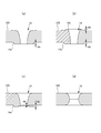
- This adhesive pattern is not particularly limited, but like the adhesive structure of the cover nonwoven fabric 20 and the liquid impermeable sheet 11 shown in FIG. It is preferable that the hot melt adhesive 20H does not exist and that the hot melt adhesive 20H exists in a continuous surface state except for the peripheral portion 14c of the region overlapping the hole 14. Since there is no hot melt adhesive 20H on the center side of the peripheral portion 14c of the region overlapping with the hole 14, the hot melt adhesive 20H does not make it sticky and the projection 14e of the hole 14 is securely fixed.
- FIGS. 11A and 11B As a typical adhesive state, as shown in FIGS. 11A and 11B, there is no hot melt adhesive 20H in the area overlapping the hole 14, and the hot melt adhesive 20H is continuous outside the area overlapping the hole 14. As shown in FIGS. 11( c) and 11 (d ), the hot melt adhesive 20 ⁇ /b>H protrudes from the peripheral portion 14 c of the area overlapping the hole 14, but the peripheral edge of the area overlapping the hole 14 as shown in FIGS. It is possible to exemplify a state in which the hot melt adhesive 20H does not exist on the center side of the portion 14c, and the hot melt adhesive 20H exists in a continuous surface state other than the peripheral portion 14c of the region overlapping the hole 14.
- the width of the hot melt adhesive 20H protruding from the peripheral portion 14c of the area overlapping the holes 14 is half the thickness of the perforated nonwoven fabric or less, and preferably about 0.5 mm or less. Further, it is desirable that the hot melt adhesive 20H does not exist in a portion of 80% or more of the area overlapping the hole 14.
- Such an adhesive structure can be formed by the method described in Patent Document 4, for example.
- the thickness is 0.30 to 1.5 mm and the minimum dimension of the hole 14 (dimension in MD direction and CD direction).
- the shorter one means, for example, the elliptical hole 14 having a long axis along the MD direction means the dimension in the CD direction, and the circle means the diameter) is 0.6 to 5 mm.
- the whiteness of the exposed surface of the perforated nonwoven fabric is 70% or more, the whiteness of the outer portion of the hole 14 is high, so that the outer portion of the hole 14 and the shadow generated on the edge of the hole 14 are separated from each other. This is preferable because the difference becomes large and the holes 14 are easily visible.
- the thickness of the perforated nonwoven fabric is particularly preferably 0.35 to 1.2 mm.
- the minimum size of the pores 14 of the perforated nonwoven fabric that is particularly preferable is 0.60 to 1.2 mm.
- the whiteness of the exposed surface of the particularly preferred porous nonwoven fabric is 73% or more, and more preferably 80% or more.
- the perforated non-woven fabric has a fineness of constituent fibers of about 1.8 to 6.0 dtex and a basis weight of about 15 to 25 g/m 2, and the lack of whiteness is caused by containing an appropriate amount of white pigment such as titanium oxide. It is preferable to supplement.
- a perforated non-woven fabric satisfying such conditions and having sufficient strength a spun-bonded non-woven fabric having perforations is preferable.
- the whiteness of the perforated non-woven fabric is preferably 85% or less.
- the display is a pattern for decoration (including pictures and one-point characters), function display such as usage and use assistance, size, etc., or mark display such as manufacturer, product name, characteristic function etc. , Is added to an appropriate member by printing or the like.
- the whiteness of the other sheet facing the supporting surface of the perforated nonwoven fabric is particularly limited.
- the surface of the other sheet on the side of the perforated nonwoven fabric is a portion exposed through the holes 14.
- the whiteness of at least the non-colored portion on the surface of the perforated nonwoven fabric in the other sheet is 70% or more, more preferably 80% or more, like the exposed surface of the perforated nonwoven fabric, this whiteness is By exposing the high portion to the inside of the hole 14, the difference between the inner portion of the hole 14 and the shadow generated on the edge of the hole 14 becomes large, and the hole 14 becomes easier to be visually recognized.
- the display may be added to other sheets facing the supporting surface of the perforated nonwoven fabric by printing or the like, and the whiteness of the colored portion for such display does not exceed 70%. Sometimes. However, since the hole 14 overlapping the colored portion has a good visibility with the colored portion as a background, at least the non-colored portion (non-printed portion) has high whiteness, and thus the visibility of the hole 14 as a whole is high. improves.
- the "front-back direction” means the direction indicated by the symbol LD in the drawing (longitudinal direction), the "width direction” means the direction indicated by WD in the drawing (left-right direction), and the front-back direction and the width direction. Are orthogonal.
- the MD direction of the nonwoven fabric is the direction of fiber orientation of the nonwoven fabric.
- the fiber orientation is the direction along which the fibers of the non-woven fabric follow, and for example, the fiber orientation can be determined from the measurement method according to the fiber orientation test method based on the zero distance tensile strength of TAPPI standard method T481 and the tensile strength ratio in the front-back direction and the width direction. It can be determined by a simple measuring method for determining the orientation direction.
- ⁇ "Front side means the side closer to the wearer's skin when wearing the pants-type disposable diaper
- back side means the side farther from the wearer's skin when wearing the pants-type disposable diaper.
- the "front side” means the side of the member that is closer to the wearer's skin when the pants-type disposable diaper is worn, and the “back side” is the skin of the wearer when the pants-type disposable diaper is worn. It means the far side.
- -"Area ratio means the ratio of the target area to the unit area, and is expressed as a percentage by dividing the total area of the target area (for example, pores) in the target area (for example, cover non-woven fabric) by the area of the target area. Is. In a form in which a large number of target portions are provided at intervals, it is desirable to set the target region to a size such that 10 or more target portions are included and obtain the area ratio.
- the area ratio of the holes can be measured by the following procedure using, for example, VHX-1000, trade name of KEYENCE, under the measurement condition of 20 times. (1) Set the lens to 20x and adjust the focus. Adjust the position of the non-woven fabric so that the holes are 4x6.
- -"Expansion rate means the value when the natural length is 100%.
- an extension rate of 200% is synonymous with an extension rate of 2 times.
- Basis weight is measured as follows. After the sample or test piece is pre-dried, the sample or test piece is left in a test room or a device in a standard state (test place is temperature 23 ⁇ 1° C., relative humidity 50 ⁇ 2%) to be in a constant weight state. Pre-drying refers to making a sample or a test piece a constant weight in an environment of a temperature of 100°C. It should be noted that the fiber having the official moisture regain of 0.0% does not need to be pre-dried. Using a template for sampling (100 mm ⁇ 100 mm), a sample having a size of 100 mm ⁇ 100 mm is cut out from the test piece in a constant weight state. The weight of the sample is measured and multiplied by 100 to calculate the weight per 1 square meter, which is used as the basis weight.
- -"Thickness is automatically measured using an automatic thickness measuring device (KES-G5 handy compression measurement program) under the conditions of load: 0.098 N/cm 2 and pressure area: 2 cm 2 .
- the thickness of the perforated nonwoven fabric is measured at a portion other than the pores and the protrusions around the pores.
- the water absorption rate is the "time to the end point" when JIS K7224-1996 "Water absorption rate test method of super absorbent polymer" is performed using 2 g of super absorbent polymer and 50 g of physiological saline. ..
- the "deployed state” means a state in which it is flatly deployed without contraction or slack.
- the dimensions of each part refer to the dimensions in the expanded state, not in the natural length state.
- Melt viscosity is measured at a specified temperature using a Brookfield B type viscometer (spindle No. 027) in accordance with JIS Z8803.
- test or measurement shall be performed in the test room or the equipment in the standard condition (test place is temperature 23 ⁇ 1°C, relative humidity 50 ⁇ 2%). To do.
- the present invention is applicable to all disposable wearable articles such as pants type disposable diapers and tape type disposable diapers, pad type disposable diapers, disposable swimwear, diaper covers, sanitary napkins and the like.
Landscapes
- Health & Medical Sciences (AREA)
- Epidemiology (AREA)
- Engineering & Computer Science (AREA)
- Biomedical Technology (AREA)
- Heart & Thoracic Surgery (AREA)
- Vascular Medicine (AREA)
- Life Sciences & Earth Sciences (AREA)
- Animal Behavior & Ethology (AREA)
- General Health & Medical Sciences (AREA)
- Public Health (AREA)
- Veterinary Medicine (AREA)
- Absorbent Articles And Supports Therefor (AREA)
- Laminated Bodies (AREA)
Priority Applications (1)
| Application Number | Priority Date | Filing Date | Title |
|---|---|---|---|
| CN201980079678.4A CN113164299B (zh) | 2018-12-20 | 2019-12-06 | 一次性穿着物品 |
Applications Claiming Priority (2)
| Application Number | Priority Date | Filing Date | Title |
|---|---|---|---|
| JP2018-238632 | 2018-12-20 | ||
| JP2018238632A JP7218170B2 (ja) | 2018-12-20 | 2018-12-20 | 使い捨て着用物品 |
Publications (1)
| Publication Number | Publication Date |
|---|---|
| WO2020129703A1 true WO2020129703A1 (ja) | 2020-06-25 |
Family
ID=71101451
Family Applications (1)
| Application Number | Title | Priority Date | Filing Date |
|---|---|---|---|
| PCT/JP2019/047815 WO2020129703A1 (ja) | 2018-12-20 | 2019-12-06 | 使い捨て着用物品 |
Country Status (4)
| Country | Link |
|---|---|
| JP (1) | JP7218170B2 (zh) |
| CN (1) | CN113164299B (zh) |
| TW (1) | TWI802776B (zh) |
| WO (1) | WO2020129703A1 (zh) |
Citations (3)
| Publication number | Priority date | Publication date | Assignee | Title |
|---|---|---|---|---|
| JP2014226215A (ja) * | 2013-05-20 | 2014-12-08 | 株式会社リブドゥコーポレーション | 吸収性物品 |
| US20170258955A1 (en) * | 2016-03-09 | 2017-09-14 | The Procter & Gamble Company | Absorbent article with activatable material |
| JP2017537680A (ja) * | 2014-11-06 | 2017-12-21 | ザ プロクター アンド ギャンブル カンパニー | パターン状有孔ウェブ、積層体、及びこれらの作成方法 |
Family Cites Families (5)
| Publication number | Priority date | Publication date | Assignee | Title |
|---|---|---|---|---|
| US5933841A (en) * | 1996-05-17 | 1999-08-03 | Ameritech Corporation | Structured document browser |
| JPH11299825A (ja) * | 1998-04-20 | 1999-11-02 | Uni Charm Corp | 使い捨ての体液吸収性物品 |
| JP2006181294A (ja) * | 2004-12-28 | 2006-07-13 | Kao Corp | 吸収性物品用の表面シート |
| JP6560015B2 (ja) * | 2014-05-30 | 2019-08-14 | 花王株式会社 | 使い捨ておむつ |
| JP6351685B2 (ja) * | 2016-10-21 | 2018-07-04 | 大王製紙株式会社 | パンツタイプ使い捨ておむつ |
-
2018
- 2018-12-20 JP JP2018238632A patent/JP7218170B2/ja active Active
-
2019
- 2019-12-06 CN CN201980079678.4A patent/CN113164299B/zh active Active
- 2019-12-06 WO PCT/JP2019/047815 patent/WO2020129703A1/ja active Application Filing
- 2019-12-19 TW TW108146559A patent/TWI802776B/zh active
Patent Citations (3)
| Publication number | Priority date | Publication date | Assignee | Title |
|---|---|---|---|---|
| JP2014226215A (ja) * | 2013-05-20 | 2014-12-08 | 株式会社リブドゥコーポレーション | 吸収性物品 |
| JP2017537680A (ja) * | 2014-11-06 | 2017-12-21 | ザ プロクター アンド ギャンブル カンパニー | パターン状有孔ウェブ、積層体、及びこれらの作成方法 |
| US20170258955A1 (en) * | 2016-03-09 | 2017-09-14 | The Procter & Gamble Company | Absorbent article with activatable material |
Also Published As
| Publication number | Publication date |
|---|---|
| CN113164299B (zh) | 2022-06-24 |
| CN113164299A (zh) | 2021-07-23 |
| JP2020099442A (ja) | 2020-07-02 |
| TW202023505A (zh) | 2020-07-01 |
| TWI802776B (zh) | 2023-05-21 |
| JP7218170B2 (ja) | 2023-02-06 |
Similar Documents
| Publication | Publication Date | Title |
|---|---|---|
| JP6144805B1 (ja) | 吸収性物品 | |
| JP6113336B1 (ja) | パンツタイプ使い捨ておむつ | |
| RU2723828C1 (ru) | Одноразовый подгузник типа трусов | |
| JP6449500B1 (ja) | 使い捨て着用物品の伸縮構造、及びこの伸縮構造を有するパンツタイプ使い捨て着用物品 | |
| WO2019188565A1 (ja) | 使い捨て着用物品の伸縮構造、及びこの伸縮構造を有するパンツタイプ使い捨て着用物品 | |
| JP6190024B1 (ja) | 有孔不織布の貼り付け方法 | |
| JP6247728B1 (ja) | 使い捨て着用物品、及び有孔不織布の貼り付け方法 | |
| WO2019188562A1 (ja) | 使い捨て着用物品の伸縮構造、及びこの伸縮構造を有するパンツタイプ使い捨て着用物品 | |
| JP6207785B1 (ja) | 使い捨て着用物品 | |
| WO2020129703A1 (ja) | 使い捨て着用物品 | |
| JP6347826B2 (ja) | パンツタイプ使い捨ておむつ | |
| JP7129190B2 (ja) | 使い捨て着用物品の伸縮構造、及びこの伸縮構造を有するパンツタイプ使い捨て着用物品 | |
| JP2020099442A5 (zh) | ||
| JP7488711B2 (ja) | 連結式使い捨て着用物品 | |
| WO2023281818A1 (ja) | 連結式使い捨て着用物品 | |
| JP7129179B2 (ja) | 吸収性物品の伸縮構造 | |
| WO2022185733A1 (ja) | パンツタイプ使い捨て着用物品 | |
| JP6452777B1 (ja) | 吸収性物品及びその製造方法 | |
| JP2019150404A (ja) | テープタイプ使い捨ておむつ | |
| JP2023009585A5 (zh) | ||
| JP2021078871A5 (zh) | ||
| CN114599323A (zh) | 一次性尿布 |
Legal Events
| Date | Code | Title | Description |
|---|---|---|---|
| 121 | Ep: the epo has been informed by wipo that ep was designated in this application |
Ref document number: 19898100 Country of ref document: EP Kind code of ref document: A1 |
|
| NENP | Non-entry into the national phase |
Ref country code: DE |
|
| 122 | Ep: pct application non-entry in european phase |
Ref document number: 19898100 Country of ref document: EP Kind code of ref document: A1 |