WO2020129699A1 - 情報管理装置、生産システム、情報管理方法およびプログラム - Google Patents
情報管理装置、生産システム、情報管理方法およびプログラム Download PDFInfo
- Publication number
- WO2020129699A1 WO2020129699A1 PCT/JP2019/047784 JP2019047784W WO2020129699A1 WO 2020129699 A1 WO2020129699 A1 WO 2020129699A1 JP 2019047784 W JP2019047784 W JP 2019047784W WO 2020129699 A1 WO2020129699 A1 WO 2020129699A1
- Authority
- WO
- WIPO (PCT)
- Prior art keywords
- operation log
- file
- log files
- information
- information management
- Prior art date
- Legal status (The legal status is an assumption and is not a legal conclusion. Google has not performed a legal analysis and makes no representation as to the accuracy of the status listed.)
- Ceased
Links
Images





Classifications
-
- G—PHYSICS
- G05—CONTROLLING; REGULATING
- G05B—CONTROL OR REGULATING SYSTEMS IN GENERAL; FUNCTIONAL ELEMENTS OF SUCH SYSTEMS; MONITORING OR TESTING ARRANGEMENTS FOR SUCH SYSTEMS OR ELEMENTS
- G05B19/00—Program-control systems
- G05B19/02—Program-control systems electric
- G05B19/418—Total factory control, i.e. centrally controlling a plurality of machines, e.g. direct or distributed numerical control [DNC], flexible manufacturing systems [FMS], integrated manufacturing systems [IMS] or computer integrated manufacturing [CIM]
-
- G—PHYSICS
- G06—COMPUTING OR CALCULATING; COUNTING
- G06F—ELECTRIC DIGITAL DATA PROCESSING
- G06F13/00—Interconnection of, or transfer of information or other signals between, memories, input/output devices or central processing units
-
- Y—GENERAL TAGGING OF NEW TECHNOLOGICAL DEVELOPMENTS; GENERAL TAGGING OF CROSS-SECTIONAL TECHNOLOGIES SPANNING OVER SEVERAL SECTIONS OF THE IPC; TECHNICAL SUBJECTS COVERED BY FORMER USPC CROSS-REFERENCE ART COLLECTIONS [XRACs] AND DIGESTS
- Y02—TECHNOLOGIES OR APPLICATIONS FOR MITIGATION OR ADAPTATION AGAINST CLIMATE CHANGE
- Y02P—CLIMATE CHANGE MITIGATION TECHNOLOGIES IN THE PRODUCTION OR PROCESSING OF GOODS
- Y02P90/00—Enabling technologies with a potential contribution to greenhouse gas [GHG] emissions mitigation
- Y02P90/02—Total factory control, e.g. smart factories, flexible manufacturing systems [FMS] or integrated manufacturing systems [IMS]
Definitions
- the present technology relates to an information management device, a production system, an information management method and a program.
- Patent Document 1 discloses a failure analysis device that analyzes log information output from an information processing system.
- the failure analysis device adds, to each log element constituting the log information, system component information indicating a system component related to the log element, and integrates each log element to which the system component information is added. Generate integrated log information.
- the present invention has been made in view of the above problems, and an object thereof is to provide an information management device, a production system, an information management method, and a program that can manage an operation log file in a production system in an easily auditable state. Is to provide.
- an information management device includes an acquisition unit for acquiring a plurality of operation log files respectively generated by a plurality of devices that configure a production system, and an integrated file that integrates a plurality of operation log files. And a generating unit for generating.
- Each of the plurality of operation log files includes an operation log element generated for each operation on the corresponding device among the plurality of devices.
- the operation log element has operation date/time information, first identification information for identifying at least one of an operator and a group to which the operator belongs, and content information indicating operation content.
- the generation unit generates an integrated file by arranging the operation log elements included in the plurality of operation log files in time series based on the operation date and time information.
- an integrated file in which operation date/time information for each operation, operator identification information, and content information are arranged in time series is generated. Accordingly, by checking the integrated file, it becomes easy to easily inspect which operator or operator belonging to which group performed what operation. That is, the information management device can manage the operation log file in the production system in an easily auditable state.
- each of the plurality of operation log files has an editable file format.
- the integrated file has a non-editable file format.
- the generation unit can easily generate the integrated file by using the operation log file having the editable file format. Further, since the integrated file has a non-editable file format, it is possible to prevent manipulation history falsification.
- the acquisition unit acquires a plurality of operation log files in an encrypted state and decrypts the plurality of operation log files.
- the generation unit adds, to the operation log element included in each of the plurality of operation log files, the second identification information for identifying the device corresponding to the operation log file.
- the generation unit changes the display format of the operation log element in the integrated file for each device based on the second identification information.
- a production system includes the above information management device and the above plurality of devices. At least one of the plurality of devices has an output processing unit for outputting an operation log file corresponding to the at least one device, and a file format of the operation log file output from the output processing unit is an editable file. And a switching unit for switching between a format and a non-editable file format.
- At least one of the above devices can output an operation log file having a non-editable file format when incorporated in a production system that does not have an information management device. This prevents tampering with the operation log file.
- the above-mentioned at least one device can be incorporated into both a production system equipped with an information management device and a production system not equipped with an information management device.
- an information management method includes a step of acquiring a plurality of operation log files respectively generated by a plurality of devices constituting a production system, and an integrated file in which the plurality of operation log files are integrated. And steps.
- Each of the plurality of operation log files includes an operation log element generated for each operation on the corresponding device among the plurality of devices.
- the operation log element has operation date/time information, first identification information for identifying at least one of an operator and a group to which the operator belongs, and content information indicating operation content.
- the step of generating includes a step of arranging the operation log elements included in the plurality of operation log files in time series based on the operation date and time information.
- a program causes a computer to execute the above information management method.
- the operation log file in the production system can be managed in an easily auditable state.
- FIG. 11 is a block diagram showing a hardware configuration of an information management device that constitutes a production system according to Modification 2.
- FIG. 11 is a block diagram showing a functional configuration of a control device and an information management device that form a production system according to Modification 2.
- FIG. 13 is a block diagram showing a functional configuration of a field device according to Modification 3.
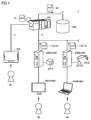
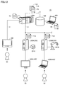
- FIG. 1 is a schematic diagram showing an outline of the production system according to the present embodiment.
- the production system 1 according to the present embodiment executes various processes related to production of industrial products.
- the production system 1 includes a control device 100, a field device 200 (including field devices 200A and 200B), an operation terminal 300, and an operation terminal 400 (including operation terminals 400A and 400B). , Database 500.
- the control device 100 is one of the devices that make up the production system 1, and corresponds to an industrial controller that controls control targets such as various types of equipment and devices.
- the control device 100 is a kind of computer that executes a control operation for controlling a control target, and may be typically embodied as a PLC (programmable controller).
- the control device 100 is connected to the field device 200, which is a control target device, via the field network 4 and controls the field device 200.
- the number of field devices 200 connected to the control device 100 is not particularly limited.
- the field device 200 transmits information to and from an actuator that exerts some physical action on a manufacturing apparatus, a production line, or the like (hereinafter collectively referred to as “field”), a sensor that detects a characteristic amount of the field, and a field. Includes input/output devices for exchange.
- the field device 200A is an image sensor that performs image processing on the image output from the camera 201A and outputs the processing result.
- the field device 200B is a robot controller that controls the operation of the robot 201B.
- the operation terminal 300 and the operation terminals 400 are terminals that accept various operations on the target device from the operator 90.
- the operation terminal 300 is communicably connected to the control device 100 via the field network 2 and receives an operation on the control device 100.
- Operation terminals 400A and 400B are connected to field devices 200A and 200B, respectively, and accept operations on field devices 200A and 200B, respectively.
- the operation terminals 300 and 400 are configured by, for example, a general-purpose computer or an HMI (Human Machine Interface), and include a display unit and an input unit.
- a general-purpose computer or an HMI (Human Machine Interface)
- HMI Human Machine Interface
- the operators 90 include an administrator who manages the production system 1, an engineer who changes the design and maintenance of the control device 100 and the field device 200, and an operator who operates the control device 100 and the field device 200 according to the process chart. included.
- the control device 100 generates an operation log file 70 indicating the operation history received from the operator 90 via the operation terminal 300.
- the field devices 200A and 200B also generate operation log files 71A and 71B indicating the operation history received from the operator 90 via the operation terminals 400A and 400B, respectively.
- Each of the operation log files 70, 71A, 71B includes an operation log element for each operation on the corresponding device.
- the operation log element has operation date/time information, operator identification information for identifying the operator 90, and content information indicating operation content.
- the operation log files 70, 71A, 71B have an editable file format (for example, CSV format).
- the control device 100 also operates as an information management device that manages the operation log file 70 generated by the control device 100 and the operation log file 71 generated by the field device 200. That is, the control device 100 acquires the operation log file 70 generated by the control device 100 and the operation log files 71A, 71B generated by the field devices 200A, 200B, respectively.
- the control device 100 generates an integrated file 80 that integrates the acquired operation log files 70, 71A, 71B. Specifically, the control device 100 arranges the operation log elements (operation date/time information, operator identification information, and content information) included in the operation log files 70, 71A, 71B in time series based on the operation date/time information. To generate the integrated file 80.
- the integrated file 80 has a non-editable file format (for example, PDF format).
- the control device 100 stores the generated integrated file 80 in the database 500.
- the database 500 is connected to the control device 100 via the local network 6.
- the integrated file 80 in which the operation date/time information, the operator identification information, and the content information for each operation on the plurality of devices (the control device 100 and the field devices 200A and 200B) configuring the production system 1 are arranged in time series. Is generated.
- the control device 100 which operates as an information management device, can manage the operation log file in the production system 1 in an easily auditable state.
- the integrated file 80 has a non-editable file format, manipulation history falsification can be prevented.
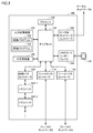
- FIG. 2 is a block diagram showing a hardware configuration example of the control device that constitutes the production system according to the present embodiment.
- the control device 100 includes a processor 102 such as a CPU (Central Processing Unit) and an MPU (Micro-Processing Unit), a chipset 104, a main storage device 106, a secondary storage device 108, A local network controller 110, a memory card interface 114, an internal bus controller 122, fieldbus controllers 118 and 120, and I/O (Input/Output) units 124-1, 124-2,... Are included.
- the processor 102 reads various programs such as the control program 112 and the management program 113 stored in the secondary storage device 108, expands the programs in the main storage device 106, and executes the programs to perform control according to the control target, and An information management process as will be described later is realized.
- the chipset 104 realizes processing as the entire control device 100 by controlling the processor 102 and each component.
- the local network controller 110 controls the exchange of data with other devices via the local network 6.
- the memory card interface 114 is configured such that the memory card 116 can be attached and detached, and data can be written in the memory card 116 and various data can be read from the memory card 116.
- the internal bus controller 122 is an interface for exchanging data with the I/O units 124-1, 124-2,... Mounted on the control device 100.
- the fieldbus controller 118 controls the exchange of data with other devices via the field network 2.
- the fieldbus controller 120 controls the exchange of data with other devices via the field network 4.
- the processing in the control device 100 is realized by a control program 112 and a management program 113 executed by the processor 102.
- the control program 112 and the management program 113 are stored in the secondary storage device 108 in advance.
- the control program 112 and the management program 113 may be stored in the memory card 116 and distributed as a program product.
- the control program 112 and the management program 113 may be provided as program products that can be downloaded by an information provider that is connected to the so-called Internet.
- FIG. 2 shows a configuration example in which necessary functions are provided by the processor 102 executing a program, but some or all of the provided functions may be provided in a dedicated hardware circuit (for example, ASIC). (Application Specific Integrated Circuit) or FPGA (Field-Programmable Gate Array) etc. may be used for implementation.
- the main part of the control device 100 may be realized by using hardware according to a general-purpose architecture (for example, an industrial personal computer based on a general-purpose personal computer).
- a virtualization technique may be used to execute a plurality of OSs (Operating Systems) having different purposes in parallel and to execute a required application on each OS.
- OSs Operating Systems
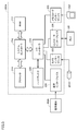
- FIG. 3 is a block diagram showing an example of the hardware configuration of the field device that constitutes the production system 1 according to the present embodiment.
- FIG. 3 shows the hardware configuration of the field device 200A that operates as an image sensor.
- the field device 200A typically has a structure according to a general-purpose computer architecture.
- the field device 200A communicates with a processor 210 such as a CPU or MPU, a RAM 212, a system controller 216, an I/O controller 218, a hard disk 220, a camera interface 222, and a controller interface 226.
- a processor 210 such as a CPU or MPU
- RAM 212 random access memory
- system controller 216 a random access memory 212
- I/O controller 218, a hard disk 220 a hard disk 220
- camera interface 222 a camera interface 222
- controller interface 226 a controller interface 226
- An interface 228 and a memory card interface 230 are included. These respective units are connected to each other so as to be able to perform data communication with each other around the system controller 216.
- the processor 210 exchanges programs (codes) and the like with the system controller 216 and executes them in a predetermined order to realize the target arithmetic processing.
- the system controller 216 is connected to the processor 210, the RAM 212, and the I/O controller 218 via buses, exchanges data with each unit, and controls the processing of the entire field device 200A.
- the RAM 212 is typically a volatile storage device such as a DRAM (Dynamic Random Access Memory), and has programs read from the hard disk 220, images (image data) taken by the camera 201A, and image processing results. And so on.
- DRAM Dynamic Random Access Memory
- the I/O controller 218 controls data exchange with a recording medium connected to the field device 200A or an external device. More specifically, the I/O controller 218 is connected to the hard disk 220, the camera interface 222, the controller interface 226, the communication interface 228, and the memory card interface 230.
- the hard disk 220 is typically a non-volatile magnetic storage device, and stores various setting values in addition to the program executed by the processor 210.
- the camera interface 222 corresponds to an input unit that receives image data captured by the camera 201A, and mediates data transmission between the processor 210 and the camera 201A.
- the camera interface 222 includes an image buffer for temporarily storing the image data from the camera 201A.
- the controller interface 226 mediates data transmission between the processor 210 and the control device 100.
- the communication interface 228 mediates data transmission between the processor 210 and the operation terminal 400A.
- the communication interface 228 is typically composed of Ethernet (registered trademark) or USB (Universal Serial Bus).
- the memory card interface 230 mediates data transmission between the processor 210 and the recording medium 232.
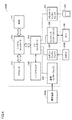
- FIG. 4 is a block diagram showing another example of the hardware configuration of the field device that constitutes the production system according to the present embodiment.
- FIG. 4 shows the hardware configuration of the field device 200B that operates as a robot controller.
- field device 200B includes a robot interface 234 instead of camera interface 222 as compared to field device 200A shown in FIG.
- the robot interface 234 mediates data transmission between the I/O controller 218 and the robot 201B.
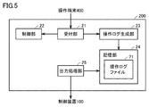
- FIG. 5 is a block diagram showing an example of the functional configuration of the field device.
- FIG. 5 shows a functional configuration relating to the generation of the operation log file.
- field device 200 includes a reception unit 21, a control unit 22, an operation log generation unit 23, a storage unit 24, and an output processing unit 25.
- the accepting unit 21 is realized by the I/O controller 218 and the communication interface 228 shown in FIG. 3 or 4.
- the control unit 22, the operation log generation unit 23, and the output processing unit 25 are realized by the processor 210 shown in FIG. 3 or 4 executing a program loaded in the RAM 212.
- the storage unit 24 is realized by the hard disk 220 shown in FIG. 3 or 4.
- the reception unit 21 receives an operation instruction from the operator 90 via the corresponding operation terminal 400.
- the operation instructions that can be accepted by the acceptance unit 21 include a login instruction, a logout instruction, an instruction to edit various data, an instruction to delete various data, an instruction to save various data, an instruction to add a user, an instruction to delete a user, an instruction to execute a program, and a program end.
- Various instructions such as instructions are included.
- the control unit 22 executes control according to the operation instruction accepted by the acceptance unit 21. For example, when the login instruction is accepted, the control unit 22 authenticates the user by collating the user ID (Identification) input to the operation terminal 400 with the registration information. When the instruction to change the setting of the data indicating the operating condition is received, the control unit 22 changes the setting of the data according to the information input to the operation terminal 300.
- the operation log generating unit 23 Each time the accepting unit 21 accepts an operation instruction, the operation log generating unit 23 generates an operation log element corresponding to the operation instruction.
- the operation log element includes at least operation date/time information indicating the date/time when the operation instruction is received, operator identification information identifying the operator who inputs the operation instruction, and content information indicating the operation content.
- the operation log generation unit 23 may generate the operation date/time information based on the clock provided in the field device 200.
- the operation log generation unit 23 outputs the operator identification information based on the user ID input at the time of login. Just generate it.
- the operation log generation unit 23 may store a table indicating the correspondence between the operation instruction and the content information in advance, and read the content information corresponding to the operation instruction received from the table.
- the operation log generation unit 23 accumulates the generated operation log elements on the data memory of the storage unit 24.
- FIG. 6 is a diagram showing an example of an operation log file generated by the field device.
- FIG. 6 shows an operation log file 71A generated by the field device 200A which is an image sensor.
- the operation log file 71 has an editable file format (for example, CSV format).
- the operation log file 71 includes an operation log element 710 generated for each operation instruction.
- the plurality of operation log elements 710 are arranged in time series in the operation log file 71.
- Each operation log element 710 includes operation date/time information 701 including operation date information 702 and operation time information 703, operator identification information 704, and content information 705.
- the operation log element 710 in the example shown in FIG. 6 further includes additional information 706.
- the attached information 706 includes information for identifying the image processing program for the image captured by the camera 201A.
- the output processing unit 25 executes data output processing to an external device.
- the output processing unit 25 executes an I/O refresh process of transmitting/receiving data to/from the control device 100 via the field network 4.
- the output processing unit 25 Upon receiving a transmission instruction of the operation log file 71 from the control device 100, the output processing unit 25 generates the operation log file 71 based on the operation log elements accumulated in the storage unit 24, and controls the generated operation log file 71. Send to the device 100.
- FIG. 7 is a block diagram showing an example of the functional configuration of the control device.
- the control device 100 includes a reception unit 11, a control unit 12, an operation log generation unit 13, a storage unit 14, an I/O processing unit 15, an acquisition unit 16, and an integrated file generation.
- the unit 17 and the deleting unit 18 are included.
- the reception unit 11 is realized by the fieldbus controller 118 shown in FIG.
- the I/O processing unit 15 is realized by the fieldbus controller 120 shown in FIG.
- the control unit 12 and the operation log generation unit 13 are realized by the processor 102 shown in FIG. 2 executing the control program 112.
- the acquisition unit 16, the integrated file generation unit 17, and the deletion unit 18 are realized by the processor 102 shown in FIG. 2 executing the management program 113.
- the storage unit 14 is realized by the main storage device 106 and the secondary storage device 108 shown in FIG.
- the reception unit 11 receives an operation instruction from the operator 90 via the operation terminal 300.
- the operation instruction that can be accepted by the acceptance unit 11 includes an instruction to output an integrated file, in addition to the operation instruction that can be accepted by the acceptance unit 21.
- the control unit 12 executes control according to the operation instruction accepted by the acceptance unit 11.
- the operation log generation unit 13 generates an operation log element corresponding to the operation instruction each time the reception unit 11 receives the operation instruction.
- the operation log generation unit 13 stores the generated operation log element in the data memory of the storage unit 14.
- the processing content of the operation log generation unit 13 is the same as the processing content of the operation log generation unit 23 of the field device 200. Therefore, detailed description of the processing content is omitted.
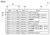
- FIG. 8 is a diagram showing an example of an operation log file generated by the control device.
- the operation log file 70 has an editable file format (for example, CSV format). As shown in FIG. 8, the operation log file 70 includes an operation log element 700 generated for each operation instruction. The plurality of operation log elements 700 are arranged in time series in the operation log file 70.
- each operation log element 700 includes operation date/time information 701 including operation date information 702 and operation time information 703, operator identification information 704, and content information 705.
- the operation log element 700 may further include additional information.
- the I/O processing unit 15 transmits/receives data (I/O refresh processing) to/from the field device 200 via the field network 4.
- the acquisition unit 16 When the reception unit 11 receives the output instruction of the integrated file, the acquisition unit 16 generates the operation log file 70 based on the operation log element accumulated in the storage unit 14. Further, the acquisition unit 16 controls the I/O processing unit 15 so as to receive the operation log file 71 from each field device 200 by the I/O refresh processing. As a result, the acquisition unit 16 acquires the operation log file 71 from each field device 200 via the I/O processing unit 15.
- the integrated file generation unit 17 generates an integrated file 80 that integrates the operation log files 70 and 71 acquired by the acquisition unit 16. Specifically, the integrated file generation unit 17 performs the following processing.
- the operation log files 70 and 71 have the editable file format as described above.
- the integrated file generation unit 17 divides the operation log file 70 into operation log elements 700 and the operation log file 71 into operation log elements 710.
- the integrated file generation unit 17 adds, to the operation log elements 700 and 710 included in each of the plurality of operation log files, device identification information that identifies a device corresponding to the operation log file.
- the integrated file generation unit 17 may add the device identification information to the operation log element based on the acquisition destination of the operation log file.
- the integrated file generation unit 17 generates the integrated file 80 by arranging the operation log elements 700 and 710 in time series based on the operation date/time information 701. At this time, the integrated file generation unit 17 generates the integrated file 80 having a non-editable file format (for example, PDF format).
- a non-editable file format for example, PDF format
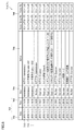
- FIG. 9 is a diagram showing an example of the integrated file.
- the integrated file 80 of the example shown in FIG. 9 is generated by integrating the operation log file 71A shown in FIG. 6 and the operation log file 70 shown in FIG.
- the integrated file 80 includes a plurality of operation log elements 800.
- Each of the plurality of operation log elements 800 corresponds to one of the operation log element 710 forming the operation log file 71A and the operation log element 700 forming the operation log file 70.
- the plurality of operation log elements 800 are arranged in time series based on the operation date/time information 701.
- each operation log element 800 includes operation date/time information 701 including operation date information 702 and operation time information 703, operator identification information 704, and content information 705.
- Each operation log element 800 further includes device identification information 707 for identifying the corresponding device (control device 100, field devices 200A, 200B).
- the operation log element 800 corresponding to the operation log element 710 further includes additional information 706.
- the operation log element 800 corresponding to the operation log element 700 may also include the additional information.
- the integrated file generation unit 17 determines whether the display format of the operation log element 800 in the integrated file 80 is different for each device based on the device identification information 707. You may let me. In the example shown in FIG. 9, the integrated file generation unit 17 makes the background pattern of the operation log element 800 different for each device.
- the method of changing the display format is not limited to this.
- the integrated file generation unit 17 may change the character color, background color, etc. of the operation log element 800 for each device. This allows the inspector to easily understand which operation log element 800 indicates an operation for which device when checking the integrated file 80.
- the deleting unit 18 executes the deleting process of the operation log files 70 and 71. Specifically, the deletion unit 18 deletes all the operation log elements 700 from the operation log file 70 stored in the storage unit 14. Further, the deletion unit 18 generates an I/O command to delete all the operation log elements 710 from the operation log file 71 (hereinafter referred to as “delete command”) and transmits the deletion command to the field device 200.
- the processing unit 15 is controlled.
- the deleting unit 18 may be omitted. Alternatively, it is possible to enable/disable the deletion process by the deletion unit 18, and the deletion unit 18 may execute the deletion process only when the deletion process is switched to the effective state.
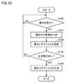
- FIG. 10 is a flowchart showing the flow of operation log file generation processing. The generation process shown in FIG. 10 is executed by each of the control device 100 and the field device 200. Hereinafter, the field device 200 will be described as an example.
- the processor 210 of the field device 200 determines whether or not an operation instruction has been received via the operation terminal 400 (step S100). When the operation instruction has not been received (NO in step S100), the operation log file generation process returns to step S100.
- step S100 When the operation instruction is received (YES in step S100), the processor 210 generates an operation log element corresponding to the operation instruction (step S102). The processor 210 accumulates the generated operation log element in the storage unit 24 (step S104). Each time the operation instruction is received, steps S102 and S104 are repeated. The processor 210 determines whether there is an operation log file generation instruction (step S106). If there is no operation log file generation instruction (NO in step S106), the operation log file generation process returns to step S100. When there is an operation log file generation instruction (YES in step S106), the processor 210 generates an operation log file based on the operation log elements accumulated in the storage unit 24 (step S108).
- FIG. 11 is a flowchart showing the flow of integrated file generation processing.
- processor 102 of control device 100 determines whether or not integrated data should be generated (step S200). For example, when the processor 102 receives an integrated file output instruction from the operation terminal 300, the processor 102 determines that the integrated file should be generated. Alternatively, the processor 102 may determine that the integrated file should be generated at the timing when the predetermined time is reached. When it is determined that the integrated file should not be generated (NO in step S200), the integrated file generation process returns to step S200.
- the processor 102 acquires the operation log files 70 and 71 (step S202). Specifically, the processor 102 generates the operation log file 70 based on the operation log elements accumulated in the storage unit 14 and acquires the operation log file 71 from the field device 200 by the I/O refresh process.
- the processor 102 generates an integrated file 80 by integrating the acquired operation log files 70 and 71 (step S204).
- the processor 102 outputs the generated integrated file 80 to the database 500 (step S206).
- FIG. 12 is a sequence diagram showing an operation example of the production system according to the present embodiment.
- the control device 100 accepts a data setting change operation via the operation terminal 300 (step S1).
- the control device 100 generates an operation log element corresponding to the setting change operation and accumulates the generated operation log element (step S2).
- the control device 100 After performing control according to the setting change operation, the control device 100 causes the operation terminal 300 to display a completion notification (step S3).
- the field device 200 accepts a data setting change operation via the operation terminal 400 (step S4).
- the field device 200 generates an operation log element corresponding to the setting change operation and accumulates the generated operation log element (step S5).
- the field device 200 controls the operation according to the setting change operation and then displays the completion notification on the operation terminal 400 (step S6).
- the control device 100 accepts an integrated file output instruction via the operation terminal 300 (step S7).
- the control device 100 starts the operation log file acquisition process in response to the output instruction (step S7).
- the control device 100 requests the field device 200 to transmit the operation log file (step S8).
- the field device 200 transmits the operation log file 71 to the control device 100 in response to the request (step S9).
- the control device 100 generates a request command for the operation log file of its own device (step S10), and generates the operation log file 70 based on the operation log element accumulated in the storage unit 14 according to the request command. (Step S11).
- control device 100 executes the integration process of the acquired operation log files 70 and 71 (step S12) and generates the integration file 80 (step S13).
- the control device 100 outputs the integrated file 80 to the database 500 (step S14).
- control device 100 may start the process of deleting the operation log file (step S15).
- the control device 100 generates a delete command of the operation log file and transmits the delete command to the field device 200 (step S16).
- the field device 200 that has received the delete command deletes all the operation log elements 710 from the storage unit 24 and sends a completion notification to the control device 100 (step S17). Further, the control device 100 deletes all the operation log elements 700 from the storage unit 14 (step S18).
- control device 100 causes the operation terminal 300 to display a completion notice indicating that the process according to the output command of step S7 is completed (step S19).
- the control device 100 includes the acquisition unit 16 and the integrated file generation unit 17.
- the acquisition unit 16 acquires the operation log files 70 and 71 generated by the control device 100 and the field device 200 that form the production system 1, respectively.
- the integrated file generation unit 17 generates an integrated file 80 that integrates the operation log files 70 and 71.
- the operation log files 70 and 71 include operation log elements 700 and 710 generated for each operation on the corresponding device.
- the operation log elements 700 and 710 have operation date/time information 701, operator identification information 704, and content information 705.
- the integrated file generation unit 17 generates the integrated file 80 by arranging the operation log elements 700 and 710 included in the operation log files 70 and 71 in time series based on the operation date/time information 701.
- control device 100 can manage the operation log file in the production system 1 in an easily auditable state.
- the operation log files 70 and 71 have editable file formats.
- the integrated file generation unit 17 can easily generate the integrated file 80 using the operation log files 70 and 71 having editable file formats.
- the integrated file 80 has a non-editable file format. Therefore, falsification of the operation history can be prevented.
- the integrated file generation unit 17 adds the device identification information 707 for identifying the device corresponding to the operation log file to the operation log element included in each of the operation log files 70 and 71. As a result, it becomes easy to easily inspect which operator performed which operation on which device.
- the integrated file generation unit 17 changes the display format of the operation log element 800 in the integrated file 80 for each device based on the device identification information 707. Accordingly, when checking the integrated file 80, it is possible to easily understand which operation log element 800 corresponds to the operation for which device.
- the output processing unit 25 of the field device 200 may encrypt the operation log file 71 using a predetermined common key, and send the encrypted operation log file 71 to the control device 100.
- the acquisition unit 16 of the control device 100 acquires a plurality of operation log files 71 in an encrypted state and decrypts the operation log files 71 using a common key stored in advance.
- control device 100 operates as a device that generates the operation log file 70 and also as an information management device that generates the integrated file 80.
- the information management device that generates the integrated file 80 may be provided separately from the control device 100.
- FIG. 13 is a schematic diagram showing an outline of the production system according to the second modification.
- the production system 1A according to the second modification is different from the production system 1 shown in FIG. 1 in that it includes a control device 100A instead of the control device 100 and further includes an information management device 600.
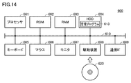
- FIG. 14 is a block diagram showing the hardware configuration of the information management device that constitutes the production system according to the second modification.
- the information management device 600 has a processor 601, which executes a program, a ROM 602, data generated by the execution of the program by the processor 601, or a keyboard 605 or a mouse 606 as main components.
- a RAM 603 that stores input data in a volatile manner
- an HDD 604 that stores data in a nonvolatile manner
- a keyboard 605 and a mouse 606 that receive input, a monitor 607, a driving device 608, and a communication IF 609 are included.
- the respective components are connected to each other by a data bus 610.
- a recording medium 620 such as a DVD-ROM is attached to the drive device 608.
- the processing in the information management device 600 is realized by the management program 613 executed by each hardware and the processor 601.
- a management program 613 is stored in the HDD 604 in advance.
- the management program 613 may be stored in the recording medium 620 and distributed as a program product.
- the management program may be provided as a program product that can be downloaded by an information provider who is connected to the so-called Internet.
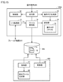
- FIG. 15 is a block diagram showing a functional configuration of a control device and an information management device that constitute the production system according to the second modification.
- the control device 100A is different from the control device shown in FIG. 7 in that a file management unit 19 is included instead of the acquisition unit 16, the integrated file generation unit 17, and the deletion unit 18.
- the file management unit 19 is realized by the processor 102 shown in FIG. 2 executing the control program 112.
- the I/O processing unit 15 of the control device 100A requests the field device 200 to transmit the operation log file 71 at a predetermined timing, and receives the operation log file 71 from the field device 200.
- the file management unit 19 registers in the database 500 the operation log file 71 received from the field device 200 and the operation log file 70 generated based on the operation log elements accumulated in the storage unit 14. At this time, the file management unit 19 encrypts the operation log files 70 and 71 using a predetermined common key and stores the encrypted operation log files 70 and 71 in the database 500 as in the first modification. Preferably.
- the information management device 600 includes an acquisition unit 61, an integrated file generation unit 62, and a deletion unit 63.
- the acquisition unit 61, the integrated file generation unit 62, and the deletion unit 63 are realized by the processor 601 illustrated in FIG. 14 executing the management program 613.
- the acquisition unit 61 acquires the operation log files 70 and 71 from the database 500 at a predetermined timing. Alternatively, the acquisition unit 61 may acquire the operation log files 70 and 71 from the database 500 at the timing when the output instruction of the integrated file is input. When the operation log files 70 and 71 are encrypted, the acquisition unit 61 may decrypt the operation log files 70 and 71 using the common key stored in advance.
- the integrated file generation unit 62 integrates the operation log files 70 and 71 and generates an integrated file 80.
- the processing content of the integrated file generation unit 62 is the same as the processing content of the integrated file generation unit 17 described above. Therefore, detailed description of the processing content of the integrated file generation unit 62 will be omitted.
- the deletion unit 63 deletes the operation log files 70 and 71 from the database 500 when the integrated file 80 is generated.
- the field device 200 needs to output the operation log file 71 having the editable file format.
- the field device 200 may be incorporated in a production system that does not include the control device 100 or the information management device 600. In such a case, the field device 200 preferably outputs the operation log file 70 having a non-editable file format in order to prevent the contents from being tampered with.
- FIG. 16 is a block diagram showing the functional configuration of the field device according to Modification 3.
- field device 250 according to Modification 3 is different from field device 200 shown in FIG. 5 in that switching device 26 is further provided.
- the switching unit 26 is realized by the processor 210 illustrated in FIG. 3 or 4 executing the program loaded in the RAM 212.
- the switching unit 26 changes the file format of the operation log file 71 output from the output processing unit 25 according to an operation by the operator 90, such as an editable file format (eg CSV format) and an uneditable file format (eg (PDF format).
- an editable file format eg CSV format
- an uneditable file format eg (PDF format).
- the output processing unit 25 generates an operation log file 71 having the file format switched by the switching unit 26 based on the operation log elements accumulated in the storage unit 24, and outputs the generated operation log file 71.
- the field device 250 can be incorporated into both a production system that includes a device that can generate the integrated file 80 and a production system that does not include a device that can generate the integrated file 80.
- the field device 250 may output an operation log file having a non-editable file format when incorporated into a production system that does not include a device that can generate the integrated file 80. This prevents tampering with the operation log file.
- the operation log files 70 and 71 include the operator identification information 704.
- the operation log files 70, 71 may include group identification information for identifying the group to which the operator belongs, instead of the operator identification information 704. In this case, by confirming the integrated file 80 in which the operation log files 70 and 71 are integrated, it is possible to easily grasp the operator who belongs to which group and what operation was performed on which device. You can
- Each of the plurality of operation log files includes an operation log element generated for each operation on a corresponding device of the plurality of devices,
- the operation log element includes operation date/time information, first identification information for identifying at least one of an operator and a group to which the operator belongs, and content information indicating operation content,
- Each of the plurality of operation log files has an editable file format,
- the generation unit (17, 62) adds, to the operation log element included in each of the plurality of operation log files, second identification information for identifying a device corresponding to the operation log file.
- An information management device (100, 600) according to any one of 1.
- the generation unit (17, 62) changes the display format of the operation log element in the integrated file for each of the devices (100, 200A, 200B) based on the second identification information.
- FIG. 6 An information management device (100, 600) according to any one of configurations 1 to 5;
- a production system (1, 1A) comprising the plurality of devices (100, 200A, 200B, 250), At least one device (250) of the plurality of devices,
- An output processing unit (25) for outputting an operation log file corresponding to the at least one device,
- a production system (1, 1A) including a switching unit (26) for switching the file format of the operation log file output from the output processing unit to either an editable file format or an uneditable file format. ).
- (Structure 7) A step of acquiring a plurality of operation log files respectively generated by a plurality of devices (100, 200A, 200B) configuring the production system (1, 1A), Generating an integrated file that integrates the plurality of operation log files,
- Each of the plurality of operation log files includes an operation log element generated for each operation on a corresponding device of the plurality of devices,
- the operation log element includes operation date/time information, first identification information for identifying at least one of an operator and a group to which the operator belongs, and content information indicating operation content
- the information management method wherein the generating step includes a step of arranging the operation log elements included in the plurality of operation log files in time series based on the operation date and time information.
- the information management method is A step of acquiring a plurality of operation log files respectively generated by a plurality of devices (100, 200A, 200B) configuring the production system (1, 1A), Generating an integrated file that integrates the plurality of operation log files,
- Each of the plurality of operation log files includes an operation log element generated for each operation on a corresponding device of the plurality of devices,
- the operation log element includes operation date/time information, first identification information for identifying at least one of an operator and a group to which the operator belongs, and content information indicating operation content
- the program wherein the generating step includes a step of arranging the operation log elements included in the plurality of operation log files in chronological order based on the operation date and time information.
- 1,1A production system 1,4 field network, 6 local network, 11,21 reception unit, 12,22 control unit, 13,23 operation log generation unit, 14,24 storage unit, 15 I/O processing unit, 16 , 61 acquisition unit, 17, 62 integrated file generation unit, 18, 63 deletion unit, 19 file management unit, 25 output processing unit, 26 switching unit, 70, 71, 71A, 71B operation log file, 80 integrated file, 90 operations Person, 100,100A control device, 102,210,601 processor, 104 chipset, 106 main storage device, 108 secondary storage device, 110 local network controller, 112 control program, 113,613 management program, 114,230 memory card Interface, 116 memory card, 118, 120 fieldbus controller, 122 internal bus controller, 124 I/O unit, 200, 200A, 200B, 250 field device, 201A camera, 201B robot, 212,603 RAM, 216 system controller, 218 I/O controller, 220 hard disk, 222 camera interface, 226 controller interface, 228 communication interface, 232,620
Landscapes
- Engineering & Computer Science (AREA)
- Physics & Mathematics (AREA)
- General Engineering & Computer Science (AREA)
- General Physics & Mathematics (AREA)
- Theoretical Computer Science (AREA)
- Manufacturing & Machinery (AREA)
- Quality & Reliability (AREA)
- Automation & Control Theory (AREA)
- General Factory Administration (AREA)
- Computer And Data Communications (AREA)
Abstract
情報管理装置は、生産システムを構成する複数の機器によってそれぞれ生成された複数の操作ログファイルを取得する取得部と、複数の操作ログファイルを統合した統合ファイルを生成する生成部とを備える。各操作ログファイルは、対応する機器への操作ごとに生成される操作ログ要素を含む。操作ログ要素は、操作日時情報と操作者を識別する第1識別情報と操作内容を示す内容情報とを有する。生成部は、操作日時情報に基づいて、複数の操作ログファイルに含まれる操作ログ要素を時系列に並べることにより統合ファイルを生成する。これにより、生産システムにおける操作ログファイルを監査しやすい状態で管理できる。
Description
本技術は、情報管理装置、生産システム、情報管理方法およびプログラムに関する。
特許第6233411号公報(特許文献1)は、情報処理システムから出力されるログ情報を分析する障害分析装置を開示している。障害分析装置は、ログ情報を構成する各ログ要素に対して、当該ログ要素に関連するシステム構成要素を表すシステム構成要素情報を付加し、システム構成要素情報が付加された各ログ要素を統合した統合ログ情報を生成する。
米国食品医薬品局(Food and Drug Administration:FDA)の規則「FDA 21 CFR Part 11」は、生産システムにおける操作内容を記録する監査証跡機能を要求している。この要求を満たすためには、どの操作者またはどのグループに属する操作者がいつどのような操作を行なったのかを示す操作ログファイルを監査しやすい状態で管理しておくことが好ましい。しかしながら、特許第6233411号公報に記載の技術は、生産システムにおける情報管理を想定していない。
本発明は、上記の問題を鑑みてなされたものであり、その目的は、生産システムにおける操作ログファイルを監査しやすい状態で管理することができる情報管理装置、生産システム、情報管理方法およびプログラムを提供することである。
本開示の一例によれば、情報管理装置は、生産システムを構成する複数の機器によってそれぞれ生成された複数の操作ログファイルを取得するための取得部と、複数の操作ログファイルを統合した統合ファイルを生成するための生成部とを備える。複数の操作ログファイルの各々は、複数の機器のうち対応する機器への操作ごとに生成される操作ログ要素を含む。操作ログ要素は、操作日時情報と、操作者および操作者が属するグループの少なくとも一方を識別する第1識別情報と、操作内容を示す内容情報とを有する。生成部は、操作日時情報に基づいて、複数の操作ログファイルに含まれる操作ログ要素を時系列に並べることにより統合ファイルを生成する。
この開示によれば、操作ごとの操作日時情報、操作者識別情報および内容情報が時系列に並べられた統合ファイルが生成される。これにより、統合ファイルを確認することにより、どの操作者またはどのグループに属する操作者がいつどのような操作を行なったのかを容易に監査しやすくなる。すなわち、情報管理装置は、生産システムにおける操作ログファイルを監査しやすい状態で管理することができる。
上述の開示において、複数の操作ログファイルの各々は、編集可能なファイル形式を有する。統合ファイルは、編集不可能なファイル形式を有する。
この開示によれば、生成部は、編集可能なファイル形式を有する操作ログファイルを用いて、統合ファイルを容易に生成できる。さらに、統合ファイルが編集不可能なファイル形式を有するため、操作履歴の改竄を防止することができる。
上述の開示において、取得部は、複数の操作ログファイルを暗号化された状態で取得し、複数の操作ログファイルを復号化する。
この開示によれば、機器から情報管理装置に送信される操作ログファイルに対する改竄を防止することができる。
上述の開示において、生成部は、複数の操作ログファイルの各々に含まれる操作ログ要素に、当該操作ログファイルに対応する機器を識別する第2識別情報を付加する。
この開示によれば、どの操作者またはどのグループに属する操作者がどの機器に対していつどのような操作を行なったのかを容易に監査しやすくなる。
上述の開示において、生成部は、第2識別情報に基づいて、統合ファイルにおける操作ログ要素の表示形式を機器ごとに異ならせる。
この開示によれば、統合ファイルを確認する際に、どの操作ログ要素がどの機器に対する操作に対応するのかを容易に把握することができる。
本開示の一例によれば、生産システムは、上記の情報管理装置と、上記の複数の機器とを備える。複数の機器の少なくとも1つの機器は、当該少なくとも1つの機器に対応する操作ログファイルを出力するための出力処理部と、出力処理部から出力される操作ログファイルのファイル形式を、編集可能なファイル形式と編集不可能なファイル形式とのいずれかに切り替える切替部とを含む。
この開示によれば、上記の少なくとも1つの機器は、情報管理装置を備えていない生産システムに組み込まれた場合に、編集不可能なファイル形式を有する操作ログファイルを出力できる。これにより、操作ログファイルの改竄を防止できる。このように、上記の少なくとも1つの機器は、情報管理装置を備えている生産システムおよび情報管理装置を備えていない生産システムのどちらにも組み込み可能である。
本開示の一例によれば、情報管理方法は、生産システムを構成する複数の機器によってそれぞれ生成された複数の操作ログファイルを取得するステップと、複数の操作ログファイルを統合した統合ファイルを生成するステップとを備える。複数の操作ログファイルの各々は、複数の機器のうちの対応する機器への操作ごとに生成される操作ログ要素を含む。操作ログ要素は、操作日時情報と、操作者および操作者が属するグループの少なくとも一方を識別する第1識別情報と、操作内容を示す内容情報とを有する。生成するステップは、操作日時情報に基づいて、複数の操作ログファイルに含まれる操作ログ要素を時系列に並べるステップを含む。
本開示の一例によれば、プログラムは、上記の情報管理方法をコンピュータに実行させる。
これらの開示によっても、生産システムにおける操作ログファイルを監査しやすい状態で管理することができる。
本発明によれば、生産システムにおける操作ログファイルを監査しやすい状態で管理することができる。
本発明の実施の形態について、図面を参照しながら詳細に説明する。なお、図中の同一または相当部分については、同一符号を付してその説明は繰返さない。
§1 適用例
まず、図1を参照して、本発明が適用される場面の一例について説明する。図1は、本実施の形態に係る生産システムの概要を示す模式図である。本実施の形態に係る生産システム1は、工業製品の生産に関する各種工程を実行する。
まず、図1を参照して、本発明が適用される場面の一例について説明する。図1は、本実施の形態に係る生産システムの概要を示す模式図である。本実施の形態に係る生産システム1は、工業製品の生産に関する各種工程を実行する。
図1に示されるように、生産システム1は、制御装置100と、フィールド機器200(フィールド機器200A,200Bを含む)と、操作端末300と、操作端末400(操作端末400A,400Bを含む)と、データベース500とを備える。
制御装置100は、生産システム1を構成する機器の1つであり、各種の設備や装置などの制御対象を制御する産業用コントローラに相当する。制御装置100は、制御対象を制御するための制御演算を実行する一種のコンピュータであり、典型的には、PLC(プログラマブルコントローラ)として具現化されてもよい。制御装置100は、フィールドネットワーク4を介して制御対象機器であるフィールド機器200に接続され、フィールド機器200を制御する。なお、制御装置100に接続されるフィールド機器200の個数は、特に限定されない。
フィールド機器200は、製造装置や生産ラインなど(以下、「フィールド」とも総称する。)に対して何らかの物理的な作用を与えるアクチュエータ、フィールドの特徴量を検出するセンサ、フィールドとの間で情報を遣り取りする入出力装置などを含む。図1に示す例では、フィールド機器200Aは、カメラ201Aから出力された画像に対して画像処理を行ない、処理結果を出力する画像センサである。フィールド機器200Bは、ロボット201Bの動作を制御するロボットコントローラである。
操作端末300および操作端末400(400A,400B)は、操作者90からの対象機器に対する各種操作を受け付ける端末である。図1に示す例では、操作端末300は、フィールドネットワーク2によって制御装置100と通信可能に接続され、制御装置100に対する操作を受け付ける。操作端末400A,400Bは、フィールド機器200A,200Bにそれぞれ接続され、フィールド機器200A,200Bに対する操作をそれぞれ受け付ける。
操作端末300,400は、例えば汎用されているコンピュータまたはHMI(Human Machine Interface)によって構成され、表示部および入力部を含む。
操作者90には、生産システム1を管理する管理者、制御装置100およびフィールド機器200の設計変更、メンテナンスなどを行なうエンジニア、および、工程表に従って制御装置100およびフィールド機器200を動作させる作業者が含まれる。
制御装置100は、操作端末300を介して操作者90から受け付けた操作履歴を示す操作ログファイル70を生成する。フィールド機器200A,200Bも、操作端末400A,400Bを介して操作者90から受け付けた操作履歴を示す操作ログファイル71A,71Bをそれぞれ生成する。操作ログファイル70,71A,71Bの各々は、対応する機器に対する操作ごとの操作ログ要素を含む。操作ログ要素は、操作日時情報と、操作者90を識別する操作者識別情報と、操作内容を示す内容情報とを有する。操作ログファイル70,71A,71Bは、編集可能なファイル形式(例えばCSV形式)を有している。
制御装置100は、制御装置100によって生成された操作ログファイル70とフィールド機器200によって生成された操作ログファイル71とを管理する情報管理装置としても動作する。すなわち、制御装置100は、制御装置100によって生成された操作ログファイル70とフィールド機器200A,200Bによってそれぞれ生成された操作ログファイル71A,71Bとを取得する。制御装置100は、取得した操作ログファイル70,71A,71Bを統合した統合ファイル80を生成する。具体的には、制御装置100は、操作日時情報に基づいて、操作ログファイル70,71A,71Bに含まれる操作ログ要素(操作日時情報、操作者識別情報および内容情報)を時系列に並べることにより統合ファイル80を生成する。統合ファイル80は、編集不可能なファイル形式(例えばPDF形式)を有する。制御装置100は、生成した統合ファイル80をデータベース500に格納する。データベース500は、ローカルネットワーク6を介して制御装置100と接続される。
このようにして、生産システム1を構成する複数の機器(制御装置100およびフィールド機器200A,200B)に対する操作ごとの操作日時情報、操作者識別情報および内容情報が時系列に並べられた統合ファイル80が生成される。これにより、統合ファイル80を確認することにより、どの操作者がいつどのような操作を行なったのかを容易に監査しやすくなる。すなわち、情報管理装置として動作する制御装置100は、生産システム1における操作ログファイルを監査しやすい状態で管理することができる。
さらに、統合ファイル80が編集不可能なファイル形式を有することにより、操作履歴の改竄を防止できる。
§2 具体例
次に、本実施の形態に係る生産システムの具体例について説明する。
次に、本実施の形態に係る生産システムの具体例について説明する。
<A.制御装置のハードウェア構成例>
図2は、本実施の形態に係る生産システムを構成する制御装置のハードウェア構成例を示すブロック図である。図2を参照して、制御装置100は、CPU(Central Processing Unit)やMPU(Micro-Processing Unit)などのプロセッサ102と、チップセット104と、主記憶装置106と、二次記憶装置108と、ローカルネットワークコントローラ110と、メモリカードインターフェイス114と、内部バスコントローラ122と、フィールドバスコントローラ118,120と、I/O(Input/Output)ユニット124-1,124-2,…とを含む。
図2は、本実施の形態に係る生産システムを構成する制御装置のハードウェア構成例を示すブロック図である。図2を参照して、制御装置100は、CPU(Central Processing Unit)やMPU(Micro-Processing Unit)などのプロセッサ102と、チップセット104と、主記憶装置106と、二次記憶装置108と、ローカルネットワークコントローラ110と、メモリカードインターフェイス114と、内部バスコントローラ122と、フィールドバスコントローラ118,120と、I/O(Input/Output)ユニット124-1,124-2,…とを含む。
プロセッサ102は、二次記憶装置108に格納された制御プログラム112、管理プログラム113などの各種プログラムを読み出して、主記憶装置106に展開して実行することで、制御対象に応じた制御、および、後述するような情報管理処理を実現する。チップセット104は、プロセッサ102と各コンポーネントを制御することで、制御装置100全体としての処理を実現する。
ローカルネットワークコントローラ110は、ローカルネットワーク6を介した他の装置との間のデータの遣り取りを制御する。メモリカードインターフェイス114は、メモリカード116を着脱可能に構成されており、メモリカード116に対してデータを書込み、メモリカード116から各種データを読出すことが可能になっている。
内部バスコントローラ122は、制御装置100に搭載されるI/Oユニット124-1,124-2,…との間でデータを遣り取りするインターフェイスである。
フィールドバスコントローラ118は、フィールドネットワーク2を介した他の装置との間のデータの遣り取りを制御する。同様に、フィールドバスコントローラ120は、フィールドネットワーク4を介した他の装置との間のデータの遣り取りを制御する。
制御装置100における処理は、プロセッサ102により実行される制御プログラム112および管理プログラム113によって実現される。このような制御プログラム112および管理プログラム113は、二次記憶装置108に予め記憶されている。もしくは、制御プログラム112および管理プログラム113は、メモリカード116に格納されて、プログラムプロダクトとして流通していてもよい。あるいは、制御プログラム112および管理プログラム113は、いわゆるインターネットに接続されている情報提供事業者によってダウンロード可能なプログラムプロダクトとして提供されてもよい。
図2には、プロセッサ102がプログラムを実行することで必要な機能が提供される構成例を示したが、これらの提供される機能の一部または全部を、専用のハードウェア回路(たとえば、ASIC(Application Specific Integrated Circuit)またはFPGA(Field-Programmable Gate Array)など)を用いて実装してもよい。あるいは、制御装置100の主要部を、汎用的なアーキテクチャに従うハードウェア(たとえば、汎用パソコンをベースとした産業用パソコン)を用いて実現してもよい。この場合には、仮想化技術を用いて、用途の異なる複数のOS(Operating System)を並列的に実行させるとともに、各OS上で必要なアプリケーションを実行させるようにしてもよい。
<B.フィールド機器のハードウェア構成例>
図3は、本実施の形態に係る生産システム1を構成するフィールド機器のハードウェア構成の一例を示すブロック図である。図3には、画像センサとして動作するフィールド機器200Aのハードウェア構成が示される。フィールド機器200Aは、典型的には、汎用的なコンピュータアーキテクチャに従う構造を有している。
図3は、本実施の形態に係る生産システム1を構成するフィールド機器のハードウェア構成の一例を示すブロック図である。図3には、画像センサとして動作するフィールド機器200Aのハードウェア構成が示される。フィールド機器200Aは、典型的には、汎用的なコンピュータアーキテクチャに従う構造を有している。
より具体的には、フィールド機器200Aは、CPUやMPUなどのプロセッサ210と、RAM212と、システムコントローラ216と、I/Oコントローラ218と、ハードディスク220と、カメラインターフェイス222と、コントローラインターフェイス226と、通信インターフェイス228と、メモリカードインターフェイス230とを含む。これらの各部は、システムコントローラ216を中心として、互いにデータ通信可能に接続される。
プロセッサ210は、システムコントローラ216との間でプログラム(コード)などを交換して、これらを所定順序で実行することで、目的の演算処理を実現する。
システムコントローラ216は、プロセッサ210、RAM212、およびI/Oコントローラ218とそれぞれバスを介して接続されており、各部との間でデータ交換などを行うとともに、フィールド機器200A全体の処理を司る。
RAM212は、典型的には、DRAM(Dynamic Random Access Memory)などの揮発性の記憶装置であり、ハードディスク220から読み出されたプログラムや、カメラ201Aによって撮像された画像(画像データ)および画像処理結果などを保持する。
I/Oコントローラ218は、フィールド機器200Aに接続される記録媒体や外部機器との間のデータ交換を制御する。より具体的には、I/Oコントローラ218は、ハードディスク220と、カメラインターフェイス222と、コントローラインターフェイス226と、通信インターフェイス228と、メモリカードインターフェイス230と接続される。
ハードディスク220は、典型的には、不揮発性の磁気記憶装置であり、プロセッサ210で実行されるプログラムに加えて、各種設定値などが格納される。
カメラインターフェイス222は、カメラ201Aによって撮像された画像データを受付ける入力部に相当し、プロセッサ210とカメラ201Aとの間のデータ伝送を仲介する。カメラインターフェイス222は、カメラ201Aからの画像データをそれぞれ一時的に蓄積するための画像バッファを含む。
コントローラインターフェイス226は、プロセッサ210と制御装置100との間のデータ伝送を仲介する。
通信インターフェイス228は、プロセッサ210と操作端末400Aとの間のデータ伝送を仲介する。通信インターフェイス228は、典型的には、イーサネット(登録商標)やUSB(Universal Serial Bus)などからなる。
メモリカードインターフェイス230は、プロセッサ210と記録媒体232との間のデータ伝送を仲介する。
図4は、本実施の形態に係る生産システムを構成するフィールド機器のハードウェア構成の別の例を示すブロック図である。図4には、ロボットコントローラとして動作するフィールド機器200Bのハードウェア構成が示される。図4を参照して、フィールド機器200Bは、図3に示すフィールド機器200Aと比較して、カメラインターフェイス222の代わりにロボットインターフェイス234を含む。ロボットインターフェイス234は、I/Oコントローラ218とロボット201Bとの間のデータ伝送を仲介する。
<C.フィールド機器の機構構成例>
図5は、フィールド機器の機能構成の一例を示すブロック図である。図5には、操作ログファイルの生成に関する機能構成が示される。図5を参照して、フィールド機器200は、受付部21と、制御部22と、操作ログ生成部23と、記憶部24と、出力処理部25とを含む。受付部21は、図3または図4に示すI/Oコントローラ218および通信インターフェイス228によって実現される。制御部22,操作ログ生成部23および出力処理部25は、図3または図4に示すプロセッサ210がRAM212に展開されたプログラムを実行することによって実現される。記憶部24は、図3または図4に示すハードディスク220によって実現される。
図5は、フィールド機器の機能構成の一例を示すブロック図である。図5には、操作ログファイルの生成に関する機能構成が示される。図5を参照して、フィールド機器200は、受付部21と、制御部22と、操作ログ生成部23と、記憶部24と、出力処理部25とを含む。受付部21は、図3または図4に示すI/Oコントローラ218および通信インターフェイス228によって実現される。制御部22,操作ログ生成部23および出力処理部25は、図3または図4に示すプロセッサ210がRAM212に展開されたプログラムを実行することによって実現される。記憶部24は、図3または図4に示すハードディスク220によって実現される。
受付部21は、対応する操作端末400を介して操作者90からの操作指示を受け付ける。受付部21が受け付け可能な操作指示には、ログイン指示、ログアウト指示、各種データの編集指示、各種データの削除指示、各種データの保存指示、ユーザ追加指示、ユーザ削除指示、プログラム実行指示、プログラム終了指示など様々な指示が含まれる。
制御部22は、受付部21が受け付けた操作指示に応じた制御を実行する。例えば、ログイン指示が受け付けられた場合、制御部22は、操作端末400に入力されたユーザID(Identification)と登録情報との照合により、ユーザ認証を行なう。動作条件を示すデータの設定変更指示が受け付けられた場合、制御部22は、操作端末300に入力された情報に従って当該データの設定変更を行なう。
操作ログ生成部23は、受付部21が操作指示を受け付けるたびに、当該操作指示に対応する操作ログ要素を生成する。操作ログ要素は、少なくとも、操作指示を受け付けた日時を示す操作日時情報と、操作指示を入力した操作者を識別する操作者識別情報と、操作内容を示す内容情報とを含む。操作ログ生成部23は、フィールド機器200に備えられる時計に基づいて、操作日時情報を生成すればよい、操作ログ生成部23は、ログイン時に入力されたユーザIDに基づいて、操作者識別情報を生成すればよい。操作ログ生成部23は、操作指示と内容情報との対応関係を示すテーブルを予め記憶しておき、当該テーブルから受け付けた操作指示に対応する内容情報を読み出せばよい。
操作ログ生成部23は、生成した操作ログ要素を、記憶部24のデータメモリ上に蓄積する。
図6は、フィールド機器によって生成される操作ログファイルの一例を示す図である。図6には、画像センサであるフィールド機器200Aによって生成された操作ログファイル71Aが示される。操作ログファイル71は、編集可能なファイル形式(例えばCSV形式)を有する。
図6に示されるように、操作ログファイル71は、操作指示ごとに生成される操作ログ要素710を含む。複数の操作ログ要素710は、操作ログファイル71において時系列に並べられる。
各操作ログ要素710は、操作日情報702および操作時刻情報703からなる操作日時情報701と、操作者識別情報704と、内容情報705とを含む。図6に示す例の操作ログ要素710は、さらに付属情報706を含む。付属情報706は、カメラ201Aで撮像された画像に対する画像処理プログラムを識別する情報を含む。
図5に戻って、出力処理部25は、外部装置へのデータの出力処理を実行する。例えば、出力処理部25は、フィールドネットワーク4を介して制御装置100との間でデータを送受信するI/Oリフレッシュ処理を実行する。出力処理部25は、制御装置100から操作ログファイル71の送信指示を受けると、記憶部24に蓄積された操作ログ要素に基づいて操作ログファイル71を生成し、生成した操作ログファイル71を制御装置100に送信する。
<D.制御装置の機構構成例>
図7は、制御装置の機能構成の一例を示すブロック図である。図7を参照して、制御装置100は、受付部11と、制御部12と、操作ログ生成部13と、記憶部14と、I/O処理部15と、取得部16と、統合ファイル生成部17と、削除部18とを含む。受付部11は、図2に示すフィールドバスコントローラ118によって実現される。I/O処理部15は、図2に示すフィールドバスコントローラ120によって実現される。制御部12および操作ログ生成部13は、図2に示すプロセッサ102が制御プログラム112を実行することによって実現される。取得部16、統合ファイル生成部17および削除部18は、図2に示すプロセッサ102が管理プログラム113を実行することによって実現される。記憶部14は、図2に示す主記憶装置106および二次記憶装置108によって実現される。
図7は、制御装置の機能構成の一例を示すブロック図である。図7を参照して、制御装置100は、受付部11と、制御部12と、操作ログ生成部13と、記憶部14と、I/O処理部15と、取得部16と、統合ファイル生成部17と、削除部18とを含む。受付部11は、図2に示すフィールドバスコントローラ118によって実現される。I/O処理部15は、図2に示すフィールドバスコントローラ120によって実現される。制御部12および操作ログ生成部13は、図2に示すプロセッサ102が制御プログラム112を実行することによって実現される。取得部16、統合ファイル生成部17および削除部18は、図2に示すプロセッサ102が管理プログラム113を実行することによって実現される。記憶部14は、図2に示す主記憶装置106および二次記憶装置108によって実現される。
受付部11は、操作端末300を介して操作者90からの操作指示を受け付ける。受付部11が受け付け可能な操作指示には、上記の受付部21が受け付け可能な操作指示の他に、統合ファイルの出力指示が含まれる。
制御部12は、受付部11が受け付けた操作指示に応じた制御を実行する。操作ログ生成部13は、受付部11が操作指示を受け付けるたびに、当該操作指示に対応する操作ログ要素を生成する。操作ログ生成部13は、生成した操作ログ要素を、記憶部14のデータメモリに蓄積する。操作ログ生成部13の処理内容は、フィールド機器200の操作ログ生成部23の処理内容と同様である。そのため、当該処理内容の詳細な説明を省略する。
図8は、制御装置によって生成される操作ログファイルの一例を示す図である。操作ログファイル70は、編集可能なファイル形式(例えばCSV形式)を有する。図8に示されるように、操作ログファイル70は、操作指示ごとに生成される操作ログ要素700を含む。複数の操作ログ要素700は、操作ログファイル70において時系列に並べられる。
各操作ログ要素700は、図6に示す操作ログ要素710と同様に、操作日情報702および操作時刻情報703からなる操作日時情報701と、操作者識別情報704と、内容情報705とを含む。操作ログ要素700は、さらに付属情報を含んでもよい。
図7に戻って、I/O処理部15は、フィールドネットワーク4を介して、フィールド機器200との間でデータの送受信(I/Oリフレッシュ処理)を行なう。
取得部16は、受付部11が統合ファイルの出力指示を受け付けると、記憶部14に蓄積された操作ログ要素に基づいて操作ログファイル70を生成する。さらに、取得部16は、I/Oリフレッシュ処理によって各フィールド機器200から操作ログファイル71を受けるようにI/O処理部15を制御する。これにより、取得部16は、I/O処理部15を介して、各フィールド機器200から操作ログファイル71を取得する。
統合ファイル生成部17は、取得部16によって取得された操作ログファイル70,71を統合した統合ファイル80を生成する。具体的には、統合ファイル生成部17は、以下の処理を行なう。
操作ログファイル70,71は、上述したように編集可能なファイル形式を有する。統合ファイル生成部17は、操作ログファイル70を操作ログ要素700ごとに分割するとともに、操作ログファイル71を操作ログ要素710ごとに分割する。
統合ファイル生成部17は、複数の操作ログファイルの各々に含まれる操作ログ要素700,710に対して、当該操作ログファイルに対応する機器を識別する機器識別情報を付加する。統合ファイル生成部17は、操作ログファイルの取得先に基づいて、機器識別情報を操作ログ要素に付加すればよい。
統合ファイル生成部17は、操作日時情報701に基づいて、操作ログ要素700,710を時系列に並べることにより統合ファイル80を生成する。このとき、統合ファイル生成部17は、編集不可能なファイル形式(例えばPDF形式)を有する統合ファイル80を生成する。
図9は、統合ファイルの一例を示す図である。図9に示す例の統合ファイル80は、図6に示す操作ログファイル71Aと図8に示す操作ログファイル70とを統合することにより生成される。図9を参照して、統合ファイル80は、複数の操作ログ要素800を含む。複数の操作ログ要素800の各々は、操作ログファイル71Aを構成する操作ログ要素710および操作ログファイル70を構成する操作ログ要素700のいずれかに対応する。複数の操作ログ要素800は、操作日時情報701に基づいて、時系列に並べられている。
各操作ログ要素800は、操作ログ要素700,710と同様に、操作日情報702および操作時刻情報703からなる操作日時情報701と、操作者識別情報704と、内容情報705とを含む。各操作ログ要素800は、対応する機器(制御装置100、フィールド機器200A,200B)を識別する機器識別情報707をさらに含む。操作ログ要素710に対応する操作ログ要素800は、さらに付属情報706を含む。操作ログ要素700が付属情報を含む場合には、操作ログ要素700に対応する操作ログ要素800も当該付属情報を含んでもよい。
図9に示されるような統合ファイル80を確認することにより、時間経過とともにどの操作者がどの機器に対してどのような操作を行なったのかを容易に監査しやすくなる。
なお、図9に示されるように、統合ファイル生成部17は、統合ファイル80を生成する際に、機器識別情報707に基づいて、統合ファイル80における操作ログ要素800の表示形式を機器ごとに異ならせてもよい。図9に示す例では、統合ファイル生成部17は、操作ログ要素800の背景パターンを機器ごとに異ならせている。表示形式の異ならせる方法は、これに限定されない。例えば、統合ファイル生成部17は、操作ログ要素800の文字色、背景色などを機器ごとに異ならせてもよい。これにより、監査員は、統合ファイル80を確認する際に、どの操作ログ要素800がどの機器に対する操作を示すのかを容易に把握することができる。
図7に戻って、削除部18は、操作ログファイル70,71の削除処理を実行する。具体的には、削除部18は、記憶部14が記憶する操作ログファイル70から全ての操作ログ要素700を削除する。さらに、削除部18は、操作ログファイル71から全ての操作ログ要素710を削除するコマンド(以下、「削除コマンド」という)を生成し、当該削除コマンドをフィールド機器200に送信するようにI/O処理部15を制御する。なお、削除部18は省略されてもよい。もしくは、削除部18による削除処理の有効/無効が切り替え可能であり、有効に切り替えられた場合にのみ、削除部18は削除処理を実行してもよい。
<E.操作ログファイルの管理処理の流れ>
図10は、操作ログファイルの生成処理の流れを示すフローチャートである。図10に示す生成処理は、制御装置100およびフィールド機器200の各々で実行される。以下、フィールド機器200を例にとり説明する。
図10は、操作ログファイルの生成処理の流れを示すフローチャートである。図10に示す生成処理は、制御装置100およびフィールド機器200の各々で実行される。以下、フィールド機器200を例にとり説明する。
まず、フィールド機器200のプロセッサ210は、操作端末400を介して操作指示を受け付けた否かを判定する(ステップS100)。操作指示を受け付けていない場合(ステップS100でNO)、操作ログファイルの生成処理はステップS100に戻る。
操作指示を受け付けた場合(ステップS100でYES)、プロセッサ210は、当該操作指示に対応する操作ログ要素を生成する(ステップS102)。プロセッサ210は、生成した操作ログ要素を記憶部24に蓄積する(ステップS104)。操作指示を受け付けるたびにステップS102,S104が繰り返される。プロセッサ210は、操作ログファイルの生成指示の有無を判定する(ステップS106)。操作ログファイルの生成指示がない場合(ステップS106でNO)、操作ログファイルの生成処理はステップS100に戻る。操作ログファイルの生成指示がある場合(ステップS106でYES)、プロセッサ210は、記憶部24に蓄積された操作ログ要素に基づいて操作ログファイルを生成する(ステップS108)。
図11は、統合ファイルの生成処理の流れを示すフローチャートである。図11を参照して、制御装置100のプロセッサ102は、統合データを生成すべきか否かを判定する(ステップS200)。例えば、プロセッサ102は、操作端末300から統合ファイルの出力指示を受け付けた場合に、統合ファイルを生成すべきであると判定する。もしくは、プロセッサ102は、予め定められた時刻に到達したタイミングにおいて、統合ファイルを生成すべきであると判定してもよい。統合ファイルを生成すべきでないと判定した場合(ステップS200でNO)、統合ファイルの生成処理はステップS200に戻る。
統合ファイルを生成すべきであると判定した場合(ステップS200でYES)、プロセッサ102は、操作ログファイル70,71を取得する(ステップS202)。具体的には、プロセッサ102は、記憶部14に蓄積された操作ログ要素に基づいて操作ログファイル70を生成するとともに、I/Oリフレッシュ処理によってフィールド機器200から操作ログファイル71を取得する。
プロセッサ102は、取得した操作ログファイル70,71を統合することにより統合ファイル80を生成する(ステップS204)。プロセッサ102は、生成した統合ファイル80をデータベース500に出力する(ステップS206)。
図12は、本実施の形態に係る生産システムの動作例を示すシーケンス図である。図12に示す例では、制御装置100は、操作端末300を介して、データの設定変更操作を受け付ける(ステップS1)。制御装置100は、当該設定変更操作に対応する操作ログ要素を生成し、生成した操作ログ要素を蓄積する(ステップS2)。制御装置100は、設定変更操作に従った制御を行なった後、完了通知を操作端末300に表示させる(ステップS3)。
次に、フィールド機器200は、操作端末400を介して、データの設定変更操作を受け付ける(ステップS4)。フィールド機器200は、当該設定変更操作に対応する操作ログ要素を生成し、生成した操作ログ要素を蓄積する(ステップS5)。フィールド機器200は、設定変更操作に従った制御を行なった後、完了通知を操作端末400に表示させる(ステップS6)。
次に、制御装置100は、操作端末300を介して、統合ファイルの出力指示を受け付ける(ステップS7)。制御装置100は、当該出力指示に応じて、操作ログファイルの取得処理を開始する(ステップS7)。制御装置100は、フィールド機器200に対して操作ログファイルの送信を要求する(ステップS8)。フィールド機器200は、当該要求に応じて操作ログファイル71を制御装置100に送信する(ステップS9)。さらに、制御装置100は、自装置の操作ログファイルの要求コマンドを生成し(ステップS10)、当該要求コマンドに応じて記憶部14に蓄積された操作ログ要素に基づいて操作ログファイル70を生成する(ステップS11)。
次に、制御装置100は、取得した操作ログファイル70,71の統合処理を実行し(ステップS12)、統合ファイル80を生成する(ステップS13)。制御装置100は、統合ファイル80をデータベース500に出力する(ステップS14)。
次に、制御装置100は、操作ログファイルの削除処理を開始してもよい(ステップS15)。制御装置100は、操作ログファイルの削除コマンドを生成し、当該削除コマンドをフィールド機器200に送信する(ステップS16)。削除コマンドを受けたフィールド機器200は、記憶部24から全ての操作ログ要素710を削除し、完了通知を制御装置100に送信する(ステップS17)。さらに、制御装置100は、記憶部14から全ての操作ログ要素700を削除する(ステップS18)。
制御装置100は、操作ログファイルの削除が完了すると、ステップS7の出力指令に応じた処理が完了したことを示す完了通知を操作端末300に表示させる(ステップS19)。
<F.作用・効果>
以上のように、本実施の形態に係る制御装置100は、取得部16と統合ファイル生成部17とを備える。取得部16は、生産システム1を構成する制御装置100およびフィールド機器200によってそれぞれ生成された操作ログファイル70,71を取得する。統合ファイル生成部17は、操作ログファイル70,71を統合した統合ファイル80を生成する。操作ログファイル70,71は、対応する機器への操作ごとに生成される操作ログ要素700,710をそれぞれ含む。操作ログ要素700,710は、操作日時情報701と、操作者識別情報704と、内容情報705とを有する。統合ファイル生成部17は、操作日時情報701に基づいて、操作ログファイル70,71に含まれる操作ログ要素700,710を時系列に並べることにより統合ファイル80を生成する。
以上のように、本実施の形態に係る制御装置100は、取得部16と統合ファイル生成部17とを備える。取得部16は、生産システム1を構成する制御装置100およびフィールド機器200によってそれぞれ生成された操作ログファイル70,71を取得する。統合ファイル生成部17は、操作ログファイル70,71を統合した統合ファイル80を生成する。操作ログファイル70,71は、対応する機器への操作ごとに生成される操作ログ要素700,710をそれぞれ含む。操作ログ要素700,710は、操作日時情報701と、操作者識別情報704と、内容情報705とを有する。統合ファイル生成部17は、操作日時情報701に基づいて、操作ログファイル70,71に含まれる操作ログ要素700,710を時系列に並べることにより統合ファイル80を生成する。
これにより、統合ファイル80を確認することにより、どの操作者がいつどのような操作を行なったのかを容易に監査しやすくなる。すなわち、制御装置100は、生産システム1における操作ログファイルを監査しやすい状態で管理することができる。
操作ログファイル70,71は、編集可能なファイル形式を有する。統合ファイル生成部17は、編集可能なファイル形式を有する操作ログファイル70,71を用いて、統合ファイル80を容易に生成できる。統合ファイル80は、編集不可能なファイル形式を有する。そのため、操作履歴の改竄を防止することができる。
統合ファイル生成部17は、操作ログファイル70,71の各々に含まれる操作ログ要素に、当該操作ログファイルに対応する機器を識別する機器識別情報707を付加する。これにより、どの操作者がどの機器に対していつどのような操作を行なったのかを容易に監査しやすくなる。
統合ファイル生成部17は、機器識別情報707に基づいて、統合ファイル80における操作ログ要素800の表示形式を機器ごとに異ならせる。これにより、統合ファイル80を確認する際に、どの操作ログ要素800がどの機器に対する操作に対応するのかを容易に把握することができる。
<G.変形例>
<G-1.変形例1>
フィールド機器200の出力処理部25は、予め定められた共通鍵を用いて操作ログファイル71を暗号化し、暗号化された操作ログファイル71を制御装置100に送信してもよい。この場合、制御装置100の取得部16は、複数の操作ログファイル71を暗号化された状態で取得し、予め記憶している共通鍵を用いて操作ログファイル71を復号化する。
<G-1.変形例1>
フィールド機器200の出力処理部25は、予め定められた共通鍵を用いて操作ログファイル71を暗号化し、暗号化された操作ログファイル71を制御装置100に送信してもよい。この場合、制御装置100の取得部16は、複数の操作ログファイル71を暗号化された状態で取得し、予め記憶している共通鍵を用いて操作ログファイル71を復号化する。
これにより、フィールド機器200から制御装置100に送信される操作ログファイル71に対する改竄を防止することができる。
<G-2.変形例2>
上記の説明では、制御装置100は、操作ログファイル70を生成する機器として動作するとともに、統合ファイル80を生成する情報管理装置としても動作する。しかしながら、統合ファイル80を生成する情報管理装置は、制御装置100と別体として設けられてもよい。
上記の説明では、制御装置100は、操作ログファイル70を生成する機器として動作するとともに、統合ファイル80を生成する情報管理装置としても動作する。しかしながら、統合ファイル80を生成する情報管理装置は、制御装置100と別体として設けられてもよい。
図13は、変形例2に係る生産システムの概要を示す模式図である。変形例2に係る生産システム1Aは、図1に示す生産システム1と比較して、制御装置100の代わりに制御装置100Aを備え、情報管理装置600をさらに備える点で相違する。
図14は、変形例2に係る生産システムを構成する情報管理装置のハードウェア構成を表わすブロック図である。図14を参照して、情報管理装置600は、主たる構成要素として、プログラムを実行するプロセッサ601と、ROM602と、プロセッサ601によるプログラムの実行により生成されたデータ、又はキーボード605もしくはマウス606を介して入力されたデータを揮発的に格納するRAM603と、データを不揮発的に格納するHDD604と、入力を受けるキーボード605およびマウス606と、モニタ607と、駆動装置608と、通信IF609とを含む。各構成要素は、相互にデータバス610によって接続されている。駆動装置608には、DVD-ROMなどの記録媒体620が装着される。
情報管理装置600における処理は、各ハードウェアおよびプロセッサ601により実行される管理プログラム613によって実現される。このような管理プログラム613は、HDD604に予め記憶されている。もしくは、管理プログラム613は、記録媒体620に格納されて、プログラムプロダクトとして流通していてもよい。あるいは、管理プログラムは、いわゆるインターネットに接続されている情報提供事業者によってダウンロード可能なプログラムプロダクトとして提供されてもよい。
図15は、変形例2に係る生産システムを構成する制御装置および情報管理装置の機能構成を示すブロック図である。制御装置100Aは、図7に示す制御装置と比較して、取得部16、統合ファイル生成部17および削除部18の代わりにファイル管理部19を含む点で相違する。ファイル管理部19は、図2に示すプロセッサ102が制御プログラム112を実行することによって実現される。
制御装置100AのI/O処理部15は、予め定められたタイミングで、フィールド機器200に対して操作ログファイル71の送信を要求し、フィールド機器200から操作ログファイル71を受ける。
ファイル管理部19は、フィールド機器200から受けた操作ログファイル71と記憶部14に蓄積された操作ログ要素に基づいて生成される操作ログファイル70とをデータベース500に登録する。このとき、ファイル管理部19は、変形例1のように、予め定められた共通鍵を用いて操作ログファイル70,71を暗号化し、暗号化された操作ログファイル70,71をデータベース500に格納することが好ましい。
情報管理装置600は、取得部61と、統合ファイル生成部62と、削除部63とを含む。取得部61、統合ファイル生成部62および削除部63は、図14に示すプロセッサ601が管理プログラム613を実行することによって実現される。
取得部61は、予め定められたタイミングで、データベース500から操作ログファイル70,71を取得する。もしくは、取得部61は、統合ファイルの出力指示が入力されたタイミングで、データベース500から操作ログファイル70,71を取得してもよい。操作ログファイル70,71が暗号化されている場合、取得部61は、予め記憶しておいた共通鍵を用いて操作ログファイル70,71を復号化すればよい。
統合ファイル生成部62は、操作ログファイル70,71を統合し、統合ファイル80を生成する。統合ファイル生成部62の処理内容は、上記の統合ファイル生成部17の処理内容と同様である。そのため、統合ファイル生成部62の処理内容の詳細については、説明を省略する。
削除部63は、統合ファイル80が生成されると、データベース500から操作ログファイル70,71を削除する。
変形例2に係る生産システム1Aによっても、情報管理装置600から出力される統合ファイル80を確認することにより、どの操作者がいつどのような操作を行なったのかを容易に監査しやすくなる。
<G-3.変形例3>
上記のように、統合ファイル80を生成可能な制御装置100または情報管理装置600を備える生産システムでは、フィールド機器200は、編集可能なファイル形式を有する操作ログファイル71を出力する必要がある。しかしながら、フィールド機器200は、な制御装置100または情報管理装置600のいずれも備えていない生産システムに組み込まれる場合もある。このような場合には、フィールド機器200は、内容の改竄を防止するために、編集不可能なファイル形式を有する操作ログファイル70を出力することが好ましい。
上記のように、統合ファイル80を生成可能な制御装置100または情報管理装置600を備える生産システムでは、フィールド機器200は、編集可能なファイル形式を有する操作ログファイル71を出力する必要がある。しかしながら、フィールド機器200は、な制御装置100または情報管理装置600のいずれも備えていない生産システムに組み込まれる場合もある。このような場合には、フィールド機器200は、内容の改竄を防止するために、編集不可能なファイル形式を有する操作ログファイル70を出力することが好ましい。
図16は、変形例3に係るフィールド機器の機能構成を示すブロック図である。図16を参照して、変形例3に係るフィールド機器250は、図5に示すフィールド機器200と比較して、切替部26をさらに備える点で相違する。切替部26は、図3または図4に示すプロセッサ210がRAM212に展開されたプログラムを実行することによって実現される。
切替部26は、操作者90からの操作に応じて、出力処理部25から出力される操作ログファイル71のファイル形式を編集可能なファイル形式(例えばCSV形式)と編集不可能なファイル形式(例えばPDF形式)とのいずれかに切り替える。
出力処理部25は、記憶部24に蓄積された操作ログ要素に基づいて、切替部26によって切り替えられたファイル形式を有する操作ログファイル71を生成し、生成した操作ログファイル71を出力する。
変形例3によれば、フィールド機器250は、統合ファイル80を生成可能な装置を備える生産システム、および、統合ファイル80を生成可能な装置を備えていない生産システムのどちらにも組み込み可能となる。フィールド機器250は、統合ファイル80を生成可能な装置を備えていない生産システムに組み込まれた場合に、編集不可能なファイル形式を有する操作ログファイルを出力すればよい。これにより、操作ログファイルの改竄を防止できる。
<G-4.変形例4>
上記の説明では、操作ログファイル70,71は、操作者識別情報704を含むものとした。しかしながら、操作ログファイル70,71は、操作者識別情報704の代わりに、操作者が属するグループを識別するグループ識別情報を含んでもよい。この場合、操作ログファイル70,71が統合された統合ファイル80を確認することにより、どのグループに属する操作者が、どの機器に対していつどのような操作を行なったのかを容易に把握することができる。
上記の説明では、操作ログファイル70,71は、操作者識別情報704を含むものとした。しかしながら、操作ログファイル70,71は、操作者識別情報704の代わりに、操作者が属するグループを識別するグループ識別情報を含んでもよい。この場合、操作ログファイル70,71が統合された統合ファイル80を確認することにより、どのグループに属する操作者が、どの機器に対していつどのような操作を行なったのかを容易に把握することができる。
<H.付記>
以上のように、本実施の形態および変形例は以下のような開示を含む。
以上のように、本実施の形態および変形例は以下のような開示を含む。
(構成1)
生産システム(1,1A)を構成する複数の機器(100,200A,200B)によってそれぞれ生成された複数の操作ログファイルを取得するための取得部(16,61)と、
前記複数の操作ログファイルを統合した統合ファイルを生成するための生成部(17,62)とを備え、
前記複数の操作ログファイルの各々は、前記複数の機器のうち対応する機器への操作ごとに生成される操作ログ要素を含み、
前記操作ログ要素は、操作日時情報と、操作者および前記操作者が属するグループの少なくとも一方を識別する第1識別情報と、操作内容を示す内容情報とを有し、
前記生成部(17,62)は、前記操作日時情報に基づいて、前記複数の操作ログファイルに含まれる前記操作ログ要素を時系列に並べることにより前記統合ファイルを生成する、情報管理装置(100,600)。
生産システム(1,1A)を構成する複数の機器(100,200A,200B)によってそれぞれ生成された複数の操作ログファイルを取得するための取得部(16,61)と、
前記複数の操作ログファイルを統合した統合ファイルを生成するための生成部(17,62)とを備え、
前記複数の操作ログファイルの各々は、前記複数の機器のうち対応する機器への操作ごとに生成される操作ログ要素を含み、
前記操作ログ要素は、操作日時情報と、操作者および前記操作者が属するグループの少なくとも一方を識別する第1識別情報と、操作内容を示す内容情報とを有し、
前記生成部(17,62)は、前記操作日時情報に基づいて、前記複数の操作ログファイルに含まれる前記操作ログ要素を時系列に並べることにより前記統合ファイルを生成する、情報管理装置(100,600)。
(構成2)
前記複数の操作ログファイルの各々は、編集可能なファイル形式を有し、
前記統合ファイルは、編集不可能なファイル形式を有する、構成1に記載の情報管理装置(100,600)。
前記複数の操作ログファイルの各々は、編集可能なファイル形式を有し、
前記統合ファイルは、編集不可能なファイル形式を有する、構成1に記載の情報管理装置(100,600)。
(構成3)
前記取得部(16,61)は、前記複数の操作ログファイルを暗号化された状態で取得し、前記複数の操作ログファイルを復号化する、構成2に記載の情報管理装置(100,600)。
前記取得部(16,61)は、前記複数の操作ログファイルを暗号化された状態で取得し、前記複数の操作ログファイルを復号化する、構成2に記載の情報管理装置(100,600)。
(構成4)
前記生成部(17,62)は、前記複数の操作ログファイルの各々に含まれる前記操作ログ要素に、当該操作ログファイルに対応する機器を識別する第2識別情報を付加する、構成1から3のいずれかに記載の情報管理装置(100,600)。
前記生成部(17,62)は、前記複数の操作ログファイルの各々に含まれる前記操作ログ要素に、当該操作ログファイルに対応する機器を識別する第2識別情報を付加する、構成1から3のいずれかに記載の情報管理装置(100,600)。
(構成5)
前記生成部(17,62)は、前記第2識別情報に基づいて、前記統合ファイルにおける前記操作ログ要素の表示形式を前記機器(100,200A,200B)ごとに異ならせる、構成4に記載の情報管理装置(100,600)。
前記生成部(17,62)は、前記第2識別情報に基づいて、前記統合ファイルにおける前記操作ログ要素の表示形式を前記機器(100,200A,200B)ごとに異ならせる、構成4に記載の情報管理装置(100,600)。
(構成6)
構成1から5のいずれかに記載の情報管理装置(100,600)と、
前記複数の機器(100,200A,200B,250)とを備える生産システム(1,1A)であって、
前記複数の機器の少なくとも1つの機器(250)は、
当該少なくとも1つの機器に対応する操作ログファイルを出力するための出力処理部(25)と、
前記出力処理部から出力される前記操作ログファイルのファイル形式を、編集可能なファイル形式と編集不可能なファイル形式とのいずれかに切り替える切替部(26)とを含む、生産システム(1,1A)。
構成1から5のいずれかに記載の情報管理装置(100,600)と、
前記複数の機器(100,200A,200B,250)とを備える生産システム(1,1A)であって、
前記複数の機器の少なくとも1つの機器(250)は、
当該少なくとも1つの機器に対応する操作ログファイルを出力するための出力処理部(25)と、
前記出力処理部から出力される前記操作ログファイルのファイル形式を、編集可能なファイル形式と編集不可能なファイル形式とのいずれかに切り替える切替部(26)とを含む、生産システム(1,1A)。
(構成7)
生産システム(1,1A)を構成する複数の機器(100,200A,200B)によってそれぞれ生成された複数の操作ログファイルを取得するステップと、
前記複数の操作ログファイルを統合した統合ファイルを生成するステップとを備え、
前記複数の操作ログファイルの各々は、前記複数の機器のうちの対応する機器への操作ごとに生成される操作ログ要素を含み、
前記操作ログ要素は、操作日時情報と、操作者および前記操作者が属するグループの少なくとも一方を識別する第1識別情報と、操作内容を示す内容情報とを有し、
前記生成するステップは、前記操作日時情報に基づいて、前記複数の操作ログファイルに含まれる前記操作ログ要素を時系列に並べるステップを含む、情報管理方法。
生産システム(1,1A)を構成する複数の機器(100,200A,200B)によってそれぞれ生成された複数の操作ログファイルを取得するステップと、
前記複数の操作ログファイルを統合した統合ファイルを生成するステップとを備え、
前記複数の操作ログファイルの各々は、前記複数の機器のうちの対応する機器への操作ごとに生成される操作ログ要素を含み、
前記操作ログ要素は、操作日時情報と、操作者および前記操作者が属するグループの少なくとも一方を識別する第1識別情報と、操作内容を示す内容情報とを有し、
前記生成するステップは、前記操作日時情報に基づいて、前記複数の操作ログファイルに含まれる前記操作ログ要素を時系列に並べるステップを含む、情報管理方法。
(構成8)
情報管理方法をコンピュータに実行させるプログラムであって、
前記情報管理方法は、
生産システム(1,1A)を構成する複数の機器(100,200A,200B)によってそれぞれ生成された複数の操作ログファイルを取得するステップと、
前記複数の操作ログファイルを統合した統合ファイルを生成するステップとを備え、
前記複数の操作ログファイルの各々は、前記複数の機器のうちの対応する機器への操作ごとに生成される操作ログ要素を含み、
前記操作ログ要素は、操作日時情報と、操作者および前記操作者が属するグループの少なくとも一方を識別する第1識別情報と、操作内容を示す内容情報とを有し、
前記生成するステップは、前記操作日時情報に基づいて、前記複数の操作ログファイルに含まれる前記操作ログ要素を時系列に並べるステップを含む、プログラム。
情報管理方法をコンピュータに実行させるプログラムであって、
前記情報管理方法は、
生産システム(1,1A)を構成する複数の機器(100,200A,200B)によってそれぞれ生成された複数の操作ログファイルを取得するステップと、
前記複数の操作ログファイルを統合した統合ファイルを生成するステップとを備え、
前記複数の操作ログファイルの各々は、前記複数の機器のうちの対応する機器への操作ごとに生成される操作ログ要素を含み、
前記操作ログ要素は、操作日時情報と、操作者および前記操作者が属するグループの少なくとも一方を識別する第1識別情報と、操作内容を示す内容情報とを有し、
前記生成するステップは、前記操作日時情報に基づいて、前記複数の操作ログファイルに含まれる前記操作ログ要素を時系列に並べるステップを含む、プログラム。
本発明の実施の形態について説明したが、今回開示された実施の形態はすべての点で例示であって制限的なものではないと考えられるべきである。本発明の範囲は請求の範囲によって示され、請求の範囲と均等の意味および範囲内でのすべての変更が含まれることが意図される。
1,1A 生産システム、2,4 フィールドネットワーク、6 ローカルネットワーク、11,21 受付部、12,22 制御部、13,23 操作ログ生成部、14,24 記憶部、15 I/O処理部、16,61 取得部、17,62 統合ファイル生成部、18,63 削除部、19 ファイル管理部、25 出力処理部、26 切替部、70,71,71A,71B 操作ログファイル、80 統合ファイル、90 操作者、100,100A 制御装置、102,210,601 プロセッサ、104 チップセット、106 主記憶装置、108 二次記憶装置、110 ローカルネットワークコントローラ、112 制御プログラム、113,613 管理プログラム、114,230 メモリカードインターフェイス、116 メモリカード、118,120 フィールドバスコントローラ、122 内部バスコントローラ、124 I/Oユニット、200,200A,200B,250 フィールド機器、201A カメラ、201B ロボット、212,603 RAM、216 システムコントローラ、218 I/Oコントローラ、220 ハードディスク、222 カメラインターフェイス、226 コントローラインターフェイス、228 通信インターフェイス、232,620 記録媒体、234 ロボットインターフェイス、300,400,400A,400B 操作端末、500 データベース、600 情報管理装置、602 ROM、604 HDD、605 キーボード、606 マウス、607 モニタ、608 駆動装置、609 通信IF、610 データバス、700,710,800 操作ログ要素、701 操作日時情報、702 操作日情報、703 操作時刻情報、704 操作者識別情報、705 内容情報、706 付属情報、707 機器識別情報。
Claims (8)
- 生産システムを構成する複数の機器によってそれぞれ生成された複数の操作ログファイルを取得するための取得部と、
前記複数の操作ログファイルを統合した統合ファイルを生成するための生成部とを備え、
前記複数の操作ログファイルの各々は、前記複数の機器のうち対応する機器への操作ごとに生成される操作ログ要素を含み、
前記操作ログ要素は、操作日時情報と、操作者および前記操作者が属するグループの少なくとも一方を識別する第1識別情報と、操作内容を示す内容情報とを有し、
前記生成部は、前記操作日時情報に基づいて、前記複数の操作ログファイルに含まれる前記操作ログ要素を時系列に並べることにより前記統合ファイルを生成する、情報管理装置。 - 前記複数の操作ログファイルの各々は、編集可能なファイル形式を有し、
前記統合ファイルは、編集不可能なファイル形式を有する、請求項1に記載の情報管理装置。 - 前記取得部は、前記複数の操作ログファイルを暗号化された状態で取得し、前記複数の操作ログファイルを復号化する、請求項2に記載の情報管理装置。
- 前記生成部は、前記複数の操作ログファイルの各々に含まれる前記操作ログ要素に、当該操作ログファイルに対応する機器を識別する第2識別情報を付加する、請求項1から3のいずれか1項に記載の情報管理装置。
- 前記生成部は、前記第2識別情報に基づいて、前記統合ファイルにおける前記操作ログ要素の表示形式を前記機器ごとに異ならせる、請求項4に記載の情報管理装置。
- 請求項1から5のいずれか1項に記載の情報管理装置と、
前記複数の機器とを備える生産システムであって、
前記複数の機器の少なくとも1つの機器は、
当該少なくとも1つの機器に対応する操作ログファイルを出力するための出力処理部と、
前記出力処理部から出力される前記操作ログファイルのファイル形式を、編集可能なファイル形式と編集不可能なファイル形式とのいずれかに切り替える切替部とを含む、生産システム。 - 生産システムを構成する複数の機器によってそれぞれ生成された複数の操作ログファイルを取得するステップと、
前記複数の操作ログファイルを統合した統合ファイルを生成するステップとを備え、
前記複数の操作ログファイルの各々は、前記複数の機器のうちの対応する機器への操作ごとに生成される操作ログ要素を含み、
前記操作ログ要素は、操作日時情報と、操作者および前記操作者が属するグループの少なくとも一方を識別する第1識別情報と、操作内容を示す内容情報とを有し、
前記生成するステップは、前記操作日時情報に基づいて、前記複数の操作ログファイルに含まれる前記操作ログ要素を時系列に並べるステップを含む、情報管理方法。 - 情報管理方法をコンピュータに実行させるプログラムであって、
前記情報管理方法は、
生産システムを構成する複数の機器によってそれぞれ生成された複数の操作ログファイルを取得するステップと、
前記複数の操作ログファイルを統合した統合ファイルを生成するステップとを備え、
前記複数の操作ログファイルの各々は、前記複数の機器のうちの対応する機器への操作ごとに生成される操作ログ要素を含み、
前記操作ログ要素は、操作日時情報と、操作者および前記操作者が属するグループの少なくとも一方を識別する第1識別情報と、操作内容を示す内容情報とを有し、
前記生成するステップは、前記操作日時情報に基づいて、前記複数の操作ログファイルに含まれる前記操作ログ要素を時系列に並べるステップを含む、プログラム。
Applications Claiming Priority (2)
| Application Number | Priority Date | Filing Date | Title |
|---|---|---|---|
| JP2018236403A JP7147542B2 (ja) | 2018-12-18 | 2018-12-18 | 情報管理装置、生産システム、情報管理方法およびプログラム |
| JP2018-236403 | 2018-12-18 |
Publications (1)
| Publication Number | Publication Date |
|---|---|
| WO2020129699A1 true WO2020129699A1 (ja) | 2020-06-25 |
Family
ID=71101545
Family Applications (1)
| Application Number | Title | Priority Date | Filing Date |
|---|---|---|---|
| PCT/JP2019/047784 Ceased WO2020129699A1 (ja) | 2018-12-18 | 2019-12-06 | 情報管理装置、生産システム、情報管理方法およびプログラム |
Country Status (2)
| Country | Link |
|---|---|
| JP (1) | JP7147542B2 (ja) |
| WO (1) | WO2020129699A1 (ja) |
Citations (4)
| Publication number | Priority date | Publication date | Assignee | Title |
|---|---|---|---|---|
| JP2010124385A (ja) * | 2008-11-21 | 2010-06-03 | Fujitsu Ltd | 端末装置及び操作情報収集システム |
| JP2010266968A (ja) * | 2009-05-12 | 2010-11-25 | Axissoft Corp | スプレッドシートへの入力データを管理するデータ管理サーバ、データ管理プログラム及びデータ管理の方法 |
| JP2015115924A (ja) * | 2013-12-16 | 2015-06-22 | 三菱電機株式会社 | 機器制御システムおよび家電機器 |
| JP2018097524A (ja) * | 2016-12-12 | 2018-06-21 | ファナック株式会社 | 操作者識別システム |
Family Cites Families (1)
| Publication number | Priority date | Publication date | Assignee | Title |
|---|---|---|---|---|
| JP2008077325A (ja) * | 2006-09-20 | 2008-04-03 | Hitachi Ltd | ストレージ装置及びストレージ装置に対する設定方法 |
-
2018
- 2018-12-18 JP JP2018236403A patent/JP7147542B2/ja active Active
-
2019
- 2019-12-06 WO PCT/JP2019/047784 patent/WO2020129699A1/ja not_active Ceased
Patent Citations (4)
| Publication number | Priority date | Publication date | Assignee | Title |
|---|---|---|---|---|
| JP2010124385A (ja) * | 2008-11-21 | 2010-06-03 | Fujitsu Ltd | 端末装置及び操作情報収集システム |
| JP2010266968A (ja) * | 2009-05-12 | 2010-11-25 | Axissoft Corp | スプレッドシートへの入力データを管理するデータ管理サーバ、データ管理プログラム及びデータ管理の方法 |
| JP2015115924A (ja) * | 2013-12-16 | 2015-06-22 | 三菱電機株式会社 | 機器制御システムおよび家電機器 |
| JP2018097524A (ja) * | 2016-12-12 | 2018-06-21 | ファナック株式会社 | 操作者識別システム |
Non-Patent Citations (1)
| Title |
|---|
| MATSUMOTO, KYOICHI: "Novel Measurement Probe Utilizing New Products Smartphones/Tablets", INSTRUMENTATION CONTROL ENGINEERING, vol. 59, no. 3, 1 March 2016 (2016-03-01), pages 53 - 55 * |
Also Published As
| Publication number | Publication date |
|---|---|
| JP7147542B2 (ja) | 2022-10-05 |
| JP2020098472A (ja) | 2020-06-25 |
Similar Documents
| Publication | Publication Date | Title |
|---|---|---|
| CN105635108B (zh) | 具有应用包分类器的防火墙 | |
| US9444693B2 (en) | Relay device, information processing system, relay device control method, image forming apparatus management method, and storage medium | |
| CN102402571B (zh) | 数据处理装置及控制方法 | |
| JP6357770B2 (ja) | 制御装置および通信制御方法 | |
| CN104573911A (zh) | 工业设备管理系统、工业设备管理装置及工业设备管理方法 | |
| WO2025200555A1 (zh) | 数据共享系统、方法、装置、计算机设备及存储介质 | |
| US10063664B2 (en) | Network system and control device | |
| Poka et al. | Design and implementation of a machine log for PBF-LB/M on basis of IoT communication architectures and an ETL pipeline | |
| JP6575311B2 (ja) | ネットワークシステムおよび制御装置 | |
| WO2019244312A1 (ja) | データ処理装置、データ処理システム、データ処理方法及びプログラム | |
| TW202303309A (zh) | 控制系統、處理裝置及控制方法 | |
| JP7147542B2 (ja) | 情報管理装置、生産システム、情報管理方法およびプログラム | |
| US20080174827A1 (en) | System and method for secure sharing of document processing device cloning data | |
| CN120652935A (zh) | 单晶炉工艺参数的管控方法、系统、设备及存储介质 | |
| JP6785572B2 (ja) | 金型電子カルテシステム | |
| EP4080394B1 (en) | Control server, data sharing system, and control program | |
| JP6576160B2 (ja) | 管理システム、管理システムの制御方法、およびプログラム | |
| WO2022022997A1 (de) | Kanalbasierte kommunikation in einem iot-netzwerk | |
| JP2025042352A (ja) | 管理システム、情報処理装置、方法およびプログラム | |
| JP7044050B2 (ja) | データ管理システムおよびデータ管理方法 | |
| JP2007299824A (ja) | プロセス情報管理装置、およびプログラム | |
| JP4697877B2 (ja) | プロセス情報管理装置、およびプログラム | |
| JP6474237B2 (ja) | 作業手順管理システム及び作業手順管理サーバ | |
| JP7379948B2 (ja) | サポート装置、サポートプログラムおよび設定方法 | |
| JP2011090505A (ja) | 情報処理システム、情報処理装置、及びプログラム |
Legal Events
| Date | Code | Title | Description |
|---|---|---|---|
| 121 | Ep: the epo has been informed by wipo that ep was designated in this application |
Ref document number: 19901319 Country of ref document: EP Kind code of ref document: A1 |
|
| NENP | Non-entry into the national phase |
Ref country code: DE |
|
| 122 | Ep: pct application non-entry in european phase |
Ref document number: 19901319 Country of ref document: EP Kind code of ref document: A1 |