WO2020129655A1 - サスペンション装置 - Google Patents
サスペンション装置 Download PDFInfo
- Publication number
- WO2020129655A1 WO2020129655A1 PCT/JP2019/047517 JP2019047517W WO2020129655A1 WO 2020129655 A1 WO2020129655 A1 WO 2020129655A1 JP 2019047517 W JP2019047517 W JP 2019047517W WO 2020129655 A1 WO2020129655 A1 WO 2020129655A1
- Authority
- WO
- WIPO (PCT)
- Prior art keywords
- cylinder
- spring guide
- suspension device
- tube
- shock absorber
- Prior art date
- Legal status (The legal status is an assumption and is not a legal conclusion. Google has not performed a legal analysis and makes no representation as to the accuracy of the status listed.)
- Ceased
Links
Images



Classifications
-
- F—MECHANICAL ENGINEERING; LIGHTING; HEATING; WEAPONS; BLASTING
- F16—ENGINEERING ELEMENTS AND UNITS; GENERAL MEASURES FOR PRODUCING AND MAINTAINING EFFECTIVE FUNCTIONING OF MACHINES OR INSTALLATIONS; THERMAL INSULATION IN GENERAL
- F16F—SPRINGS; SHOCK-ABSORBERS; MEANS FOR DAMPING VIBRATION
- F16F9/00—Springs, vibration-dampers, shock-absorbers, or similarly-constructed movement-dampers using a fluid or the equivalent as damping medium
- F16F9/32—Details
Definitions
- the present invention relates to a suspension device.
- a strut-type damper having coil springs arranged concentrically around a shock absorber is known (see US20160023529A1).
- the coil spring is arranged between the upper spring seat and the lower spring seat of the damper.
- the lower spring seat (spring guide) includes an annular member that supports the coil spring, and a tubular member that extends from the annular member.
- the tubular member is arranged around the outer tube of the shock absorber. The end of the tubular member abuts a support ring welded to the outer tube.
- the suspension device described in US20160023529A1 is used with the spring guide sandwiched between the coil spring and the support ring. Therefore, the spring guide does not come off the cylinder of the shock absorber during use of the suspension device.
- the present invention aims to improve the efficiency of the assembly work of the suspension device.
- a suspension device including a cylinder and a rod protruding from the cylinder, the shock absorber provided between a vehicle body and a wheel, and an upper mount attached to a tip of the rod.
- a spring guide attached to the outer peripheral surface of the cylinder; a coil spring provided between the spring guide and the upper mount to elastically support the vehicle body;
- a contractile member that is tightened by a contracting force, the spring guide includes an insertion hole through which the shock absorber is inserted, and a fixing portion that is tightened by the contractible member. The part and a part of the cylinder are collectively covered.
- FIG. 1 is a partial sectional view of a suspension device according to an embodiment of the present invention.
- FIG. 2 is a perspective view of the spring guide according to the embodiment of the present invention.
- FIG. 3A is an enlarged schematic cross-sectional view showing, in an enlarged manner, an attachment portion of a spring guide to a cylinder in a suspension device according to an embodiment of the present invention, and shows a state before a tube is heated.
- FIG. 3B is an enlarged cross-sectional schematic view showing an enlarged mounting portion of the spring guide with respect to the cylinder in the suspension device according to the embodiment of the present invention, and shows a state after the tube is heated and contracted.
- FIG. 4 is a diagram for explaining how to carry the intermediate assembly.
- FIG. 4 is a diagram for explaining how to carry the intermediate assembly.
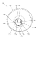
- FIG. 5 is a schematic plan cross-sectional view of the cylindrical portion of the spring guide according to the modified example 4 of the embodiment of the present invention, taken along a plane orthogonal to the axial direction.
- FIG. 6 is an enlarged schematic cross-sectional view showing, in an enlarged manner, a mounting portion of a spring guide with respect to a cylinder in a suspension device according to Modification 4 of the embodiment of the present invention.
- a suspension device 10 according to an embodiment of the present invention will be described with reference to the drawings.
- FIG. 1 is a partial cross-sectional view of the suspension device 10.
- a suspension device 10 is attached to an automobile (not shown) to position wheels (not shown) and generate a damping force to absorb shocks and vibrations received from a road surface while the vehicle is running. It is a device that stably suspends the vehicle body.
- the suspension device 10 includes a strut-type shock absorber 1 provided between a vehicle body and wheels, an upper mount 2 attached to a tip of a piston rod (hereinafter, referred to as a rod) 1a of the shock absorber 1, and a shock absorber 1 of the shock absorber 1.
- a spring guide 100 attached to the outer peripheral surface of the cylinder 1b, a coil spring 4 provided between the spring guide 100 and the upper mount 2 for elastically supporting the vehicle body, and a compression side of the shock absorber 1 fitted on the rod 1a.
- a bump stopper 5 for restricting the stroke a bump cap 6 as a cap member fitted to the end of the cylinder 1b on the rod 1a side, a dust boot 7 as a cylindrical cover member for protecting the rod 1a, and a cylinder.
- a tube 170 as a contractible member that is formed into a shape and that tightens the outer circumference of the spring guide 100 with a contracting force.
- the shock absorber 1 has a cylinder 1b and a cylindrical rod 1a protruding from an opening 142 (see FIGS. 3A and 3B) of the cylinder 1b.
- the shock absorber 1 is a double-cylinder type shock absorber, and the cylinder 1b has a bottomed cylindrical outer tube 11o forming the outer shell of the cylinder 1b and an inner tube 11i provided inside the outer tube 11o (FIG. 3A, 3B), and.
- a piston (not shown) that divides the inner tube 11i into an expansion side chamber and a compression side chamber is connected to the lower end of the rod 1a.
- the rod 1a is slidably supported by a rod holding portion 145 (see FIGS. 3A and 3B) provided at the open end of the outer tube 11o.
- the rod holding portion 145 has a laminated structure in which a dust seal, an oil seal, a bearing and the like are laminated.
- the rod holding portion 145 and the inner tube 11i are axially sandwiched by a caulking portion 141 (see FIGS. 3A and 3B) formed by crimping the upper end portion of the outer tube 11o and the bottom portion of the outer tube 11o. To be done.
- a bracket 1c for connecting a hub carrier (not shown) holding a wheel and the shock absorber 1 is provided at the end of the cylinder 1b opposite to the rod 1a side.
- the upper mount 2 side is defined as the upper side of the suspension device 10
- the bracket 1c side is defined as the lower side of the suspension device 10
- the vertical direction is defined as shown in the figure.
- the vertical direction of the suspension device 10 is the axial direction (center axis direction) of the suspension device 10 and the expansion/contraction direction of the shock absorber 1.
- the radial direction of the suspension device 10 (the radial direction of the shock absorber 1) is orthogonal to the axial direction of the suspension device 10.
- the shock absorber 1 is connected to the vehicle body via the upper mount 2 and is also attached to the vehicle by being connected to the hub carrier by the bracket 1c.
- the shock absorber 1 configured as described above is configured to generate a damping force when the rod 1a moves in the axial direction (vertical direction in FIG. 1) with respect to the cylinder 1b.
- the suspension device 10 quickly damps the vibration of the vehicle body by the damping force of the shock absorber 1.
- the coil spring 4 is sandwiched in a compressed state between the upper mount 2 and the spring guide 100, and urges the shock absorber 1 in the extension direction.
- a rubber sheet 8 is provided between the upper mount 2 and the coil spring 4.
- An arc-shaped rubber sheet 40 is provided between the spring guide 100 and the coil spring 4. This prevents the spring guide 100 and the coil spring 4 from directly contacting each other.
- FIG. 2 is a perspective view of the spring guide 100.
- the spring guide 100 is a resin-made dish-shaped member fixed to the outer periphery of the cylinder 1b.
- the spring guide 100 includes a disk-shaped base portion 110 that supports the coil spring 4, a side wall 111 that extends from the outer edge of the base portion 110 to the upper side (upper mount 2 side), and the base portion 110 that serves as an axis of the suspension device 10. Is formed so as to pass through in the direction (vertical direction) and is an opening through which the cylinder 1b of the shock absorber 1 is inserted, and an insertion hole 120 that projects upward and downward from the base 110 and surrounds the insertion hole 120.
- a cylindrical tubular portion 112 and a bottomed cylindrical hub 113 are provided.
- the periphery of the hub 113 in the base 110 is an attachment area to which the rubber sheet 40 is attached.
- the base portion 110 is provided with a position regulating portion (not shown) that regulates the position of the rubber sheet 40.
- the rubber sheet 40 is formed of a material having elasticity such as rubber.
- the rubber sheet 40 is provided with a seating portion 40a (see FIG. 1) which is curved so that its cross section follows the cross sectional shape of the coil spring 4.
- the spring guide 100 is formed with a plurality of through holes (not shown) to reduce the weight and drain water accumulated in the base 110.
- the cylindrical portion 112 protruding in the axial direction from the base portion 110 has a circular insertion hole 120 on the inner periphery thereof. As shown in FIG. 1, when the spring guide 100 is fixed to the outer circumference of the cylinder 1b, the insertion hole 120 is formed at a position eccentric to the vehicle body side from the center of the spring guide 100.
- a metal support ring 3 is fixed to the outer periphery of the cylinder 1b by welding.
- the spring guide 100 is fixed to the outer periphery of the cylinder 1b by inserting the insertion hole 120 into the outer periphery of the cylinder 1b and supporting the lower end of the cylindrical portion 112 of the spring guide 100 by the support ring 3.
- the fit between the cylinder 1b and the insertion hole 120 may be a "clearance fit” or "a clearance fit”. It may be a "shrink fit”.
- the "tight fit” is adopted, there is no play between the insertion hole 120 and the cylinder 1b, and it is possible to prevent the generation of noise due to the play. Further, the responsiveness of the operation of the suspension device 10 can be improved.
- the spring guide 100 is attached to the cylinder 1b by being fitted into the cylinder 1b from above and coming into contact with the support ring 3.
- the cylinder 1b is inserted from the lower opening end 125L of the insertion hole 120 of the spring guide 100. That is, the lower opening end 125L is an inlet into which the cylinder 1b is inserted, and the upper end of the cylinder 1b projects from the upper opening end 125U, which is the opening end opposite to the lower opening end 125L.
- the insertion hole 120 is provided with a rib 122 as a convex portion that protrudes radially inward from the inner peripheral surface 121 thereof.
- the rib 122 functions as a support portion that supports the outer peripheral surface of the cylinder 1b of the shock absorber 1.
- Each rib 122 is provided linearly along the axial direction of the insertion hole 120 (that is, the axial direction of the suspension device 10).
- the rib 122 is formed, for example, so that its cross-sectional shape is a rounded trapezoidal shape or a semicircular shape, and is in line contact with the outer peripheral surface of the cylinder 1b.
- a plurality of ribs 122 are arranged at equal intervals along the circumferential direction of the insertion hole 120. Therefore, the spring guide 100 is positioned such that the central axis of the insertion hole 120 matches the central axis of the cylinder 1b.
- the tubular portion 112 has a cylindrical main body portion 112a and a cylindrical fixed portion 112b extending from the main body portion 112a in one axial direction (upward).
- the fixing portion 112b is provided at the upper mount side end (upper end) of the tubular portion 112.
- the inner circumference of the main body 112a and the inner circumference of the fixed portion 112b are continuous, and the insertion hole 120 is formed by the inner circumference of the main body 112a and the inner circumference of the fixed portion 112b.
- the outer diameter of the fixed portion 112b is smaller than the outer diameter of the main body portion 112a. Therefore, a step portion 112c is formed on the outer peripheral surface of the upper end portion of the tubular portion 112. As shown in FIG. 3B, the fixing portion 112b is tightened radially inward by the tube 170 that collectively covers the fixing portion 112b and a part of the outer peripheral surface of the cylinder 1b.
- the tube 170 is a tubular heat-shrinking member that shrinks in the radial direction by heat and tightens the fixing portion 112b by the shrinking force.
- the tube 170 is manufactured as follows, for example.
- a resin material whose main raw material is polyethylene, polyolefin, or fluoropolymer is extruded into a cylindrical shape. After that, electron beams are irradiated to crosslink. Further, the cross-linked member is heated to soften it, the inner pressure is applied to expand the diameter, and the member is cooled to fix the shape. As a result, the tube 170 having the heat shrinkage property is completed.
- the tube 170 has elasticity in a shrinkage-cured state (state shown in FIG. 3B).
- FIGS. 3A and 3B are enlarged schematic cross-sectional views showing the attachment portion of the spring guide 100 to the cylinder 1b in an enlarged manner.
- 3A shows a state before the tube 170 is heated
- FIG. 3B shows a state after the tube 170 is heated and contracted.
- the inner diameter of the tube 170 before shrinking due to heating is larger than the outer diameter of the cylinder 1b.
- the tube 170 before contraction is arranged so as to straddle the tip of the fixed portion 112b.
- one end of the tube 170 is arranged on the step portion 112c, and the tube 170 is arranged so as to cover the outer peripheral surface of the fixed portion 112b and a part of the outer peripheral surface of the cylinder 1b from the outside in the radial direction.
- the tube 170 can be easily positioned by bringing the lower end surface of the tube 170 into contact with the end surface of the main body 112a forming the step 112c.
- the tube 170 is heated to shrink and cure. Thereby, as shown in FIG. 3B, the tube 170 comes into close contact with the fixed portion 112b and the surface of the cylinder 1b.
- the tube 170 contracts in accordance with the outer diameter of the cylinder 1b and contracts corresponding to the outer diameter of the fixed portion 112b and the cylinder contact portion 171 that adheres to the outer peripheral surface of the cylinder 1b, and the outer peripheral surface of the fixed portion 112b.
- a fixed portion close contact portion 172 that is in close contact with the fixed portion.
- the cylinder contact portion 171 and the fixed portion contact portion 172 are arranged adjacent to each other in the axial direction.
- the spring guide 100 can be fixed to the cylinder 1b by attaching the tube 170 to the cylinder 1b and heating it, the work of attaching the spring guide 100 to the cylinder 1b can be easily performed.
- the spring guide 100 is positioned in the axial direction by the lower end of the tubular portion 112 being supported by the support ring 3 (see FIG. 1) and the upper end of the tubular portion 112 being fixed by the tightening force of the tube 170. That is, the tube 170 tightens the upper end of the cylindrical portion 112 of the spring guide 100 inward in the radial direction, and restricts the axial movement of the spring guide 100 with respect to the cylinder 1b.
- the intermediate assembly 90 in which the spring guide 100 is fitted to the cylinder 1b of the shock absorber 1 is lifted by the lifting tool 91 and transported to a predetermined place. There is.
- the coil spring 4, the upper mount 2, the bump stopper 5 and the like are not attached to the intermediate assembly 90.
- the hoisting tool 91 supports the base portion 110 of the spring guide 100 so as to be lifted from below, and hoists the intermediate assembly 90.
- the upper end of the cylindrical portion 112 of the spring guide 100 is fixed to the outer peripheral surface of the cylinder 1b by the tube 170. Therefore, even when an upward external force is applied to the spring guide 100 from the suspending tool 91, the spring guide 100 can be prevented from coming off the cylinder 1b.
- the spring guide 100 since the spring guide 100 can be fixed to the cylinder 1b by the tube 170, it is not necessary to fix the spring guide 100 to the cylinder 1b by press fitting. When the resin spring guide 100 is firmly fixed to the cylinder 1b by press fitting, the spring guide 100 may be cracked by press fitting. On the other hand, in the present embodiment, since it is not necessary to fix the spring guide 100 to the cylinder 1b by press fitting, it is possible to prevent cracking due to press fitting.
- Vehicles are used in various environments. For example, when the vehicle runs in an area with a lot of snow, the suspension device 10 may come into contact with water containing a snow melting agent.
- the snow melting agent contains calcium chloride. Therefore, if water containing calcium chloride enters between the outer periphery of the cylinder 1b and the inner periphery of the insertion hole 120, the inner periphery of the insertion hole 120 may be deteriorated and damaged.
- the tube 170 covers the fixing portion 112b provided at the upper end of the cylinder portion 112 and a part of the cylinder 1b over the entire circumference of the cylinder 1b, so that the outer circumference of the cylinder 1b and the insertion hole.
- the gap with 120 is closed.
- the tube 170 can prevent foreign matter such as sand and water from entering the gap between the cylinder 1b and the insertion hole 120. Therefore, it is possible to prevent deterioration and damage due to foreign matter entering the gap between the outer circumference of the cylinder 1b and the inner circumference of the insertion hole 120.
- the tube 170 collectively covers the fixing portion 112b and a part of the cylinder 1b, and the contracting force tightens the fixing portion 112b to fix the spring guide 100 to the cylinder 1b. For this reason, in the assembly work of the suspension device 10, when an external force acts on the spring guide 100, the tube 170 restricts the axial movement of the spring guide 100 with respect to the cylinder 1b.
- ⁇ Modification 1> In the above embodiment, an example in which the tube 170 formed in advance in a cylindrical shape is arranged on the step portion 112c (see FIG. 3A) and heated to shrink and cure (see FIG. 3B) has been described, but the present invention is not limited to this. Not done.
- a strip-shaped tape is wound around the fixing portion 112b and a part of the outer peripheral surface of the cylinder 1b a plurality of times to form a tubular shape, and the tubular tape having a plurality of layers is heated to shrink and cure. May be.
- the tube 170 is a heat shrink member
- the present invention is not limited to this.
- the tube 170 may be a member that does not have a heat shrinkage property, and may be an elastic member such as rubber that elastically tightens the fixing portion 112b.
- the inner diameter of the tube 170 is smaller than the outer diameter of the cylinder 1b when no external force is applied to the tube 170.
- the tube 170 is fitted into the cylinder 1b in a state where the tube 170 is pulled radially outward and expanded in diameter (see FIG. 3A).
- the tube 170 is contracted in the radial direction by the elastic contraction force when the pulling force is released in the state where the lower end of the tube 170 is arranged in the step 112c, and the fixing portion 112b is tightened inward in the radial direction ( See FIG. 3B).
- the spring guide 100 can be fixed to the cylinder 1b by elastically deforming the tube 170 as a cylindrical elastic member and attaching it to the cylinder 1b. Therefore, the work of attaching the spring guide 100 to the cylinder 1b can be easily performed.
- the cylindrical portion 112 such that the outer diameter of the fixed portion 112b is smaller than the outer diameter of the main body portion 112a as in the above-described embodiment. As a result, it is possible to prevent excessive tensile stress from being generated in the tube 170. Moreover, since the wall thickness of the main body 112a is larger than the wall thickness of the fixed portion 112b, it is possible to secure the strength required for the tubular portion 112 that holds the outer periphery of the cylinder 1b.
- FIG. 5 is a schematic plan cross-sectional view of the cylindrical portion 212 of the spring guide 200 taken along a plane orthogonal to the axial direction
- FIG. 6 is an enlarged schematic cross-sectional view showing a mounting portion of the spring guide 200 on the cylinder 1b in an enlarged manner. Is. In FIG. 5, the structure of the cylinder 1b is omitted.
- a fixing is provided on the cylindrical portion 212 of the spring guide 200 so as to project from the end surface (upper opening edge portion of the insertion hole 120) of the main body portion 112a in one axial direction (upward).
- a plurality of parts 212b are provided.
- the spring guide 200 can be fixed to the cylinder 1b by collectively covering the fixing portion 212b and the outer peripheral surface of the cylinder 1b between the fixing portions 212b adjacent in the circumferential direction with the tube 270.
- the tube 270 according to the present modification has a cylinder contact portion 271 that adheres to the outer peripheral surface of the cylinder 1b, and a fixed portion contact portion 272 that adheres to the outer peripheral surface of the fixed portion 212b.
- the cylinder contact portion 271 and the fixed portion contact portion 272 are arranged adjacent to each other in the circumferential direction.
- the outer peripheral surface of the cylinder 1b between the fixing portions 212b adjacent to each other in the circumferential direction is covered with the tube 270. Therefore, the coating area (contact area) of the tube 270 with respect to the cylinder necessary for fixing the spring guide 200 to the cylinder 1b can be easily ensured.
- the spring guide 100 is made of resin, but the present invention is not limited to this.
- the spring guide 100 may be made of metal.
- the suspension device 10 includes a cylinder 1b and a rod 1a protruding from the cylinder 1b, a shock absorber 1 provided between a vehicle body and a wheel, an upper mount 2 attached to a tip of the rod 1a, and an outer circumference of the cylinder 1b.
- the spring guides 100 and 200 mounted on the surface, the coil spring 4 provided between the spring guides 100 and 200 and the upper mount 2 and elastically supporting the vehicle body, and the outer circumference of the spring guides 100 and 200 formed in a tubular shape.
- the spring guides 100 and 200 include insertion holes 120 through which the shock absorber 1 is inserted, and fixing portions 112b and 212b that are tightened by the tubes 170 and 270.
- the tubes 170 and 270 collectively cover the fixing portions 112b and 212b and a part of the cylinder 1b.
- the movement of the spring guides 100, 200 is restricted by the tubes 170, 270 when an external force acts on the spring guides 100, 200. This can prevent the spring guides 100 and 200 from coming off the shock absorber 1. Therefore, the efficiency of the assembly work of the suspension device 10 can be improved.
- the spring guide 100 has a tubular portion 112 having an inner periphery serving as an insertion hole 120, a fixed portion 112b is provided at an end of the tubular portion 112, and a tube 170 is provided in the fixed portion.
- a tubular portion 112 having an inner periphery serving as an insertion hole 120
- a fixed portion 112b is provided at an end of the tubular portion 112
- a tube 170 is provided in the fixed portion.
- the tube 170 can prevent foreign matter such as sand and water from entering the gap between the cylinder 1b and the insertion hole 120.
- the spring guide 200 has a cylindrical tubular portion 212 having an insertion hole 120 on the inner periphery, and the tubular portion 212 includes a main body portion 112a and a plurality of axially protruding main body portions 112a.
- the tube 270 has a fixing portion 212b and collectively covers the fixing portion 212b and the outer peripheral surface of the cylinder 1b between the fixing portions 212b adjacent in the circumferential direction.
- the outer peripheral surface of the cylinder 1b between the fixing portions 212b adjacent to each other in the circumferential direction is covered with the tube 270, so that the covering area of the tube 270 with respect to the cylinder 1b necessary for fixing the spring guide 200 to the cylinder 1b ( The contact area) can be easily secured.
- the suspension device 10 is a heat-shrinkable member in which the tubes 170 and 270 shrink due to heat, and the contracting force tightens the fixing portions 112b and 212b.
- the spring guides 100 and 200 can be fixed to the cylinder 1b by attaching the tubular tubes 170 and 270 to the cylinder 1b and heating them. It can be done easily.
- the suspension device 10 is an elastic member in which the tubes 170 and 270 elastically clamp the fixing portions 112b and 212b.
- the spring guides 100 and 200 can be fixed to the cylinder 1b by elastically deforming the tubular tubes 170 and 270 and attaching them to the cylinder 1b. Can be done easily.
Landscapes
- Engineering & Computer Science (AREA)
- General Engineering & Computer Science (AREA)
- Mechanical Engineering (AREA)
- Fluid-Damping Devices (AREA)
Abstract
サスペンション装置(10)であって、車体と車輪との間に設けられるショックアブソーバ(1)と、ロッド(1a)の先端に取り付けられるアッパーマウント(2)と、シリンダ(1b)の外周面に取り付けられるスプリングガイド(100)と、スプリングガイド(100)とアッパーマウント(2)との間に設けられ、車体を弾性支持するコイルスプリング(4)と、筒状に形成され、スプリングガイド(100)の外周を収縮力により締め付ける収縮性部材(170)と、を備え、スプリングガイド(100)は、ショックアブソーバ(1)が挿通する挿通孔(120)と、収縮性部材(170)によって締め付けられる固定部(112b)と、を有し、収縮性部材(170)は、固定部(112b)とシリンダ(1b)の一部とを一括して被覆する。
Description
本発明は、サスペンション装置に関する。
ショックアブソーバのまわりに同心円状に配設されるコイルスプリングを備えたストラット型のダンパ(サスペンション装置)が知られている(US20160023529A1参照)。コイルスプリングは、ダンパのアッパースプリングシートとロアスプリングシートとの間に配置される。ロアスプリングシート(スプリングガイド)は、コイルスプリングを支持する環状部材と、環状部材から延在する管状部材と、を備える。管状部材は、ショックアブソーバのアウターチューブの周囲に配置される。管状部材の端部は、アウターチューブに溶接された支持リングに当接する。
US20160023529A1に記載のサスペンション装置は、スプリングガイドがコイルスプリングと支持リングとの間で挟まれた状態で使用される。このため、サスペンション装置の使用中に、スプリングガイドがショックアブソーバのシリンダから外れてしまうことはない。
しかしながら、サスペンション装置を組み立てる際、ショックアブソーバのシリンダにスプリングガイドを嵌合させた状態であって、コイルスプリングが取り付けられる前の状態では、スプリングガイドに外力が作用することにより、スプリングガイドがショックアブソーバから外れてしまうおそれがある。その結果、サスペンション装置の組み立て作業の効率が悪化するおそれがある。
本発明は、サスペンション装置の組み立て作業の効率を向上することを目的とする。
本発明のある態様によれば、サスペンション装置であって、シリンダと前記シリンダから突出するロッドとを有し、車体と車輪との間に設けられるショックアブソーバと、前記ロッドの先端に取り付けられるアッパーマウントと、前記シリンダの外周面に取り付けられるスプリングガイドと、前記スプリングガイドと前記アッパーマウントとの間に設けられ、前記車体を弾性支持するコイルスプリングと、筒状に形成され、前記スプリングガイドの外周を収縮力により締め付ける収縮性部材と、を備え、前記スプリングガイドは、前記ショックアブソーバが挿通する挿通孔と、前記収縮性部材によって締め付けられる固定部と、を有し、前記収縮性部材は、前記固定部と前記シリンダの一部とを一括して被覆する。
図面を参照して、本発明の実施形態に係るサスペンション装置10について説明する。
図1は、サスペンション装置10の部分断面図である。図1に示すように、サスペンション装置10は、自動車(図示せず)に取り付けられ、車輪(図示せず)を位置決めするとともに減衰力を発生させて車両走行中に路面から受ける衝撃や振動を吸収して車体を安定的に懸架する装置である。
サスペンション装置10は、車体と車輪との間に設けられるストラット式のショックアブソーバ1と、ショックアブソーバ1のピストンロッド(以下、ロッドと記す)1aの先端に取り付けられるアッパーマウント2と、ショックアブソーバ1のシリンダ1bの外周面に取り付けられるスプリングガイド100と、スプリングガイド100とアッパーマウント2との間に設けられ、車体を弾性支持するコイルスプリング4と、ロッド1aに嵌装されショックアブソーバ1の縮み側のストロークを規制するバンプストッパ5と、シリンダ1bのロッド1a側の端部に嵌装されるキャップ部材としてのバンプキャップ6と、ロッド1aを保護する筒状のカバー部材としてのダストブーツ7と、筒状に形成され、スプリングガイド100の外周を収縮力により締め付ける収縮性部材としてのチューブ170と、を備える。
ショックアブソーバ1は、シリンダ1bと、シリンダ1bの開口部142(図3A、図3B参照)から突出する円柱状のロッド1aと、を有する。ショックアブソーバ1は、複筒型のショックアブソーバであり、シリンダ1bは、シリンダ1bの外郭を構成する有底円筒状のアウターチューブ11oと、アウターチューブ11oの内側に設けられるインナーチューブ11i(図3A、図3B参照)と、を有する。ロッド1aの下端部には、インナーチューブ11i内を伸側室と圧側室とに区画するピストン(不図示)が連結されている。
ロッド1aは、アウターチューブ11oの開口端部に設けられるロッド保持部145(図3A、図3B参照)により、摺動自在に支持される。ロッド保持部145は、ダストシール、オイルシール、軸受等が積層された積層構造とされる。ロッド保持部145及びインナーチューブ11iは、アウターチューブ11oの上端部を内側にかしめることにより形成されるかしめ部141(図3A、図3B参照)と、アウターチューブ11oの底部とによって軸方向に挟持される。
図1に示すように、シリンダ1bのロッド1a側とは反対側の端部には、車輪を保持するハブキャリア(図示せず)とショックアブソーバ1とを連結するためのブラケット1cが設けられる。説明の便宜上、アッパーマウント2側をサスペンション装置10の上側、ブラケット1c側をサスペンション装置10の下側として上下方向を図示するように規定する。なお、サスペンション装置10の上下方向は、サスペンション装置10の軸方向(中心軸方向)であり、ショックアブソーバ1の伸縮方向である。また、サスペンション装置10の径方向(ショックアブソーバ1の径方向)は、サスペンション装置10の軸方向に直交する。
ショックアブソーバ1は、アッパーマウント2を介して車体に連結されるとともに、ブラケット1cによりハブキャリアに連結されて車両に組み付けられる。このように構成されたショックアブソーバ1は、ロッド1aがシリンダ1bに対して軸方向(図1の上下方向)に移動したときに、減衰力が発生するように構成されている。サスペンション装置10は、このショックアブソーバ1の減衰力によって車体の振動を素早く減衰させる。
コイルスプリング4は、アッパーマウント2とスプリングガイド100との間に圧縮状態で挟持され、ショックアブソーバ1を伸長方向に付勢する。アッパーマウント2とコイルスプリング4との間にはラバーシート8が設けられる。これにより、アッパーマウント2とコイルスプリング4とが直接当接しないようになっている。スプリングガイド100とコイルスプリング4との間には円弧状のラバーシート40が設けられる。これにより、スプリングガイド100とコイルスプリング4とが直接当接しないようになっている。
図2は、スプリングガイド100の斜視図である。図1及び図2に示すように、スプリングガイド100は、シリンダ1bの外周に固定される樹脂製の皿状の部材である。スプリングガイド100は、コイルスプリング4を支持する円板状のベース部110と、ベース部110の外縁から上側(アッパーマウント2側)に延在する側壁111と、ベース部110をサスペンション装置10の軸方向(上下方向)に貫通するように設けられ、ショックアブソーバ1のシリンダ1bが挿通する開口部である挿通孔120と、ベース部110から上方及び下方に突出し挿通孔120を囲むように形成される円筒状の筒部112と、有底円筒形状のハブ113と、を備える。
ベース部110におけるハブ113の周囲は、ラバーシート40が取り付けられる取付領域とされる。ベース部110には、ラバーシート40の位置を規制する位置規制部(不図示)が設けられる。ラバーシート40は、ゴムなどの弾性を有する材料によって形成される。ラバーシート40には、その断面がコイルスプリング4の断面形状に沿うように湾曲して形成される着座部40a(図1参照)が設けられる。スプリングガイド100には、軽量化、及びベース部110に溜まった水を抜くために複数の貫通孔(不図示)が形成される。
ベース部110から軸方向に突出する筒部112は、その内周が円形状の挿通孔120とされている。図1に示すように、挿通孔120は、スプリングガイド100をシリンダ1bの外周に固定したときに、スプリングガイド100の中心から車体側に偏心した位置になるように形成される。
シリンダ1bの外周には、金属製の支持リング3が溶接により固定されている。スプリングガイド100は、挿通孔120がシリンダ1bの外周に嵌合され、スプリングガイド100の筒部112の下端部が支持リング3によって支持されることで、シリンダ1bの外周に固定される。
なお、シリンダ1bと挿通孔120のはめあい、具体的にはシリンダ1bと挿通孔120に形成されるリブ122(図2参照)とのはめあいは、「すきまばめ」であってもよいし、「しまりばめ」であってもよい。「しまりばめ」を採用する場合、挿通孔120とシリンダ1bとの間のガタがなくなり、ガタによる異音の発生を防止することができる。また、サスペンション装置10の動作の応答性を向上することもできる。
スプリングガイド100は、上方からシリンダ1bに嵌め込まれ、支持リング3に当接することで、シリンダ1bに取り付けられる。換言すれば、シリンダ1bは、スプリングガイド100の挿通孔120の下部開口端125Lから挿入される。つまり、下部開口端125Lは、シリンダ1bが挿入される入口であり、下部開口端125Lの反対側の開口端である上部開口端125Uからシリンダ1bの上端部が突出する。
図2に示すように、挿通孔120には、その内周面121から径方向内側に向かって突出する凸部としてのリブ122が設けられる。リブ122は、ショックアブソーバ1のシリンダ1bの外周面を支持する支持部として機能する。各リブ122は、挿通孔120の軸方向(すなわち、サスペンション装置10の軸方向)に沿って直線状に設けられる。
リブ122は、例えば、その断面形状が丸みを帯びた台形状あるいは半円形状となるように形成され、シリンダ1bの外周面に線接触する。リブ122は、挿通孔120の周方向に沿って等間隔で複数配置される。このため、スプリングガイド100は、挿通孔120の中心軸がシリンダ1bの中心軸に一致するように位置決めされる。
図2及び図3Bに示すように、筒部112は、円筒状の本体部112aと、本体部112aから軸方向一方(上方)に延在する円筒状の固定部112bと、を有する。換言すれば、筒部112のアッパーマウント側の端部(上端部)には、固定部112bが設けられている。本体部112aの内周と固定部112bの内周とは連続しており、本体部112aの内周と固定部112bの内周とによって挿通孔120が形成される。
固定部112bの外径は、本体部112aの外径よりも小さい。このため、筒部112の上端部の外周面には、段部112cが形成される。図3Bに示すように、固定部112bは、固定部112bとシリンダ1bの外周面の一部とを一括して被覆するチューブ170によって、径方向内方に向かって締め付けられる。
チューブ170は、熱によって、径方向に収縮し、その収縮力によって固定部112bを締め付ける筒状の熱収縮部材である。チューブ170は、例えば、以下のようにして製造される。
まず、ポリエチレン、ポリオレフィン、フッ素系ポリマーなどを主原料とする樹脂材を円筒状に押出成形する。その後、電子線を照射し架橋する。さらに、架橋した部材を加熱して軟化させ、内圧を加えるなどして拡径し、冷却して形状を固定する。これにより、熱収縮特性が付与されたチューブ170が完成する。なお、チューブ170は、収縮硬化した状態(図3Bに示す状態)で弾力性を有する。
図3A及び図3Bを参照して、チューブ170によってスプリングガイド100をシリンダ1bに固定する方法について説明する。図3A及び図3Bは、シリンダ1bに対するスプリングガイド100の取付部を拡大して示す拡大断面模式図である。図3Aは、チューブ170が加熱される前の状態を示し、図3Bは、チューブ170が加熱され、収縮した後の状態を示す。なお、加熱により収縮する前のチューブ170の内径は、シリンダ1bの外径よりも大きい。
まず、図3Aに示すように、固定部112bの先端を跨ぐように、収縮前のチューブ170を配置する。例えば、図示するように、チューブ170の一端部を段部112cに配置し、固定部112bの外周面及びシリンダ1bの外周面の一部を径方向外方から覆うようにチューブ170を配置する。このとき、段部112cを構成する本体部112aの端面にチューブ170の下端面を当接させることにより、簡単にチューブ170を位置決めすることができる。
図3Aに示すように、固定部112bの外周面とシリンダ1bの外周面の一部を覆うようにチューブ170を配置した後、チューブ170を加熱して収縮硬化させる。これにより、図3Bに示すように、チューブ170が固定部112bとシリンダ1bの表面に密着する。
チューブ170には、シリンダ1bの外径に対応して収縮し、シリンダ1bの外周面に密着するシリンダ密着部171と、固定部112bの外径に対応して収縮し、固定部112bの外周面に密着する固定部密着部172と、が形成される。シリンダ密着部171と固定部密着部172とは軸方向に隣接して配置される。
このように、チューブ170をシリンダ1bに取り付け、加熱することにより、スプリングガイド100をシリンダ1bに固定することができるので、スプリングガイド100をシリンダ1bに取り付ける作業を容易に行うことができる。
スプリングガイド100は、筒部112の下端部が支持リング3(図1参照)に支持され、筒部112の上端部がチューブ170による締め付け力により固定されることにより、軸方向に位置決めされる。つまり、チューブ170は、スプリングガイド100の筒部112の上端部を径方向内方に向かって締め付け、シリンダ1bに対するスプリングガイド100の軸方向の移動を規制する。
図4に示すように、サスペンション装置10を組み立てる工程において、ショックアブソーバ1のシリンダ1bにスプリングガイド100を嵌合させた状態の中間組立体90を吊り具91により吊り上げ、所定の場所まで運搬することがある。中間組立体90には、コイルスプリング4、アッパーマウント2、バンプストッパ5等が取り付けられていない。
吊り具91は、スプリングガイド100のベース部110を下方から持ち上げるように支持し、中間組立体90を吊り上げる。本実施形態では、スプリングガイド100の筒部112の上端部が、チューブ170によってシリンダ1bの外周面に固定されている。このため、吊り具91からスプリングガイド100に上向きの外力が作用した場合であっても、スプリングガイド100がシリンダ1bから外れてしまうことを防止することができる。また、本実施形態では、チューブ170によってスプリングガイド100をシリンダ1bに固定することができるので、スプリングガイド100をシリンダ1bに圧入により固定する必要がない。樹脂製のスプリングガイド100をシリンダ1bに圧入により強固に固定する場合、スプリングガイド100に圧入による割れが生じるおそれがある。これに対して、本実施形態では、スプリングガイド100をシリンダ1bに圧入により固定する必要がないので、圧入に起因する割れの発生を防止することができる。
車両は様々な環境で使用される。例えば、降雪の多い地域において車両が走行する場合、サスペンション装置10は、融雪剤を含んだ水と接触することがある。融雪剤は塩化カルシウムを含んでいる。このため、シリンダ1bの外周と挿通孔120の内周との間に塩化カルシウムを含んだ水が侵入してしまうと、挿通孔120の内周が劣化し、損傷してしまうおそれがある。
本実施形態では、チューブ170は、筒部112の上端部に設けられた固定部112bとシリンダ1bの一部とをシリンダ1bの全周に亘って被覆することにより、シリンダ1bの外周と挿通孔120との間の隙間を閉塞する。
このため、チューブ170によって、シリンダ1bと挿通孔120との間の隙間に、砂、水等の異物が侵入することを防止することができる。したがって、シリンダ1bの外周と挿通孔120の内周との間の隙間に異物が侵入することに起因した劣化、損傷を防止することができる。
上述した実施形態によれば、次の作用効果を奏する。
チューブ170が、固定部112bとシリンダ1bの一部とを一括して被覆し、その収縮力によって固定部112bを締め付け、スプリングガイド100をシリンダ1bに固定する。このため、サスペンション装置10の組み立て作業において、スプリングガイド100に外力が作用したときに、チューブ170によって、シリンダ1bに対するスプリングガイド100の軸方向の移動が規制される。
これにより、サスペンション装置10の組み立て作業において、スプリングガイド100がショックアブソーバ1から外れてしまうことを防止することができる。したがって、サスペンション装置10の組み立て作業の効率を向上することができる。
また、サスペンション装置10の組み立て作業において、吊り具91によってスプリングガイド100を支持し、中間組立体90を吊り上げ、所定の場所まで運搬するという工程を採用することもできるので、サスペンション装置10の組み立て作業の自由度が高い。
次のような変形例も本発明の範囲内であり、変形例に示す構成と上述の実施形態で説明した構成を組み合わせたり、以下の異なる変形例で説明する構成同士を組み合わせたりすることも可能である。
<変形例1>
上記実施形態では、予め筒状に形成されたチューブ170を段部112cに配置し(図3A参照)、加熱して収縮硬化させる(図3B参照)例について説明したが、本発明はこれに限定されない。例えば、熱収縮部材として、帯状のテープを固定部112bとシリンダ1bの外周面の一部に複数回巻きつけて筒状とし、複数層からなる筒状のテープを加熱して収縮硬化させるようにしてもよい。
上記実施形態では、予め筒状に形成されたチューブ170を段部112cに配置し(図3A参照)、加熱して収縮硬化させる(図3B参照)例について説明したが、本発明はこれに限定されない。例えば、熱収縮部材として、帯状のテープを固定部112bとシリンダ1bの外周面の一部に複数回巻きつけて筒状とし、複数層からなる筒状のテープを加熱して収縮硬化させるようにしてもよい。
<変形例2>
上記実施形態では、チューブ170が熱収縮部材である例について説明したが、本発明はこれに限定されない。例えば、チューブ170は、熱収縮特性を有していない部材であって、固定部112bを弾性的に締め付ける、ゴム等の弾性部材であってもよい。この場合、チューブ170に外力が作用していない状態において、チューブ170の内径は、シリンダ1bの外径よりも小さい。
上記実施形態では、チューブ170が熱収縮部材である例について説明したが、本発明はこれに限定されない。例えば、チューブ170は、熱収縮特性を有していない部材であって、固定部112bを弾性的に締め付ける、ゴム等の弾性部材であってもよい。この場合、チューブ170に外力が作用していない状態において、チューブ170の内径は、シリンダ1bの外径よりも小さい。
チューブ170は、径方向外方に引っ張られて拡径された状態でシリンダ1bに嵌め込まれる(図3A参照)。チューブ170は、その下端部が段部112cに配置された状態で、引っ張り力が解除されることにより、弾性収縮力によって径方向に収縮し、固定部112bを径方向内方に向かって締め付ける(図3B参照)。
このような変形例によれば、筒状の弾性部材としてのチューブ170を弾性変形させてシリンダ1bに取り付けることにより、スプリングガイド100をシリンダ1bに固定することができる。よって、スプリングガイド100をシリンダ1bに取り付ける作業を容易に行うことができる。
<変形例3>
上記実施形態では、スプリングガイド100の筒部112に形成される固定部112bの外径が、本体部112aの外径に比べて小さい例について説明したが(図2、図3B参照)、本発明はこれに限定されない。固定部112bの外径は、本体部112aの外径と同じにしてもよいし、本体部112aの外径よりも大きくしてもよい。
上記実施形態では、スプリングガイド100の筒部112に形成される固定部112bの外径が、本体部112aの外径に比べて小さい例について説明したが(図2、図3B参照)、本発明はこれに限定されない。固定部112bの外径は、本体部112aの外径と同じにしてもよいし、本体部112aの外径よりも大きくしてもよい。
ただし、シリンダ1bの外径と固定部112bの外径とが大きく異なると、シリンダ密着部171と固定部密着部172との間で、過大な引張応力が発生するおそれがある。このため、上記実施形態のように、本体部112aの外径に比べて、固定部112bの外径が小さくなるように筒部112を形成することが好ましい。これにより、チューブ170に過大な引張応力が発生することを防止することができる。また、本体部112aの肉厚は、固定部112bの肉厚に比べて大きいため、シリンダ1bの外周を保持する筒部112として必要な強度を確保することができる。
<変形例4>
上記実施形態では、筒部112に形成される固定部112bが、筒状とされる例について説明したが、本発明はこれに限定されない。固定部112bの形状は、種々の形状を採用することができる。図5及び図6を参照して、本実施形態の変形例4に係るスプリングガイド200とシリンダ1bの取付構造について説明する。図5は、スプリングガイド200の筒部212を軸方向に直交する平面で切断した平面断面模式図であり、図6は、シリンダ1bに対するスプリングガイド200の取付部を拡大して示す拡大断面模式図である。図5において、シリンダ1b内の構造については、図示を省略している。
上記実施形態では、筒部112に形成される固定部112bが、筒状とされる例について説明したが、本発明はこれに限定されない。固定部112bの形状は、種々の形状を採用することができる。図5及び図6を参照して、本実施形態の変形例4に係るスプリングガイド200とシリンダ1bの取付構造について説明する。図5は、スプリングガイド200の筒部212を軸方向に直交する平面で切断した平面断面模式図であり、図6は、シリンダ1bに対するスプリングガイド200の取付部を拡大して示す拡大断面模式図である。図5において、シリンダ1b内の構造については、図示を省略している。
本変形例では、図5及び図6に示すように、スプリングガイド200の筒部212に、本体部112aの端面(挿通孔120の上部開口縁部)から軸方向一方(上方)に突出する固定部212bが複数設けられる。
本変形例では、固定部212bと、周方向に隣り合う固定部212b間におけるシリンダ1bの外周面とを、チューブ270によって一括被覆することにより、スプリングガイド200をシリンダ1bに固定することができる。本変形例に係るチューブ270は、シリンダ1bの外周面に密着するシリンダ密着部271と、固定部212bの外周面に密着する固定部密着部272と、を有する。シリンダ密着部271と固定部密着部272とは周方向に隣接して配置される。本変形例では、周方向に隣り合う固定部212b間におけるシリンダ1bの外周面がチューブ270によって被覆される。そのため、シリンダ1bにスプリングガイド200を固定するのに必要なシリンダに対するチューブ270の被覆面積(接触面積)を容易に確保することができる。
<変形例5>
上記実施形態では、スプリングガイド100が樹脂製である例について説明したが、本発明はこれに限定されない。例えば、スプリングガイド100は、金属により形成してもよい。
上記実施形態では、スプリングガイド100が樹脂製である例について説明したが、本発明はこれに限定されない。例えば、スプリングガイド100は、金属により形成してもよい。
以上のように構成された本発明の実施形態の構成、作用、および効果をまとめて説明する。
サスペンション装置10は、シリンダ1bとシリンダ1bから突出するロッド1aとを有し、車体と車輪との間に設けられるショックアブソーバ1と、ロッド1aの先端に取り付けられるアッパーマウント2と、シリンダ1bの外周面に取り付けられるスプリングガイド100,200と、スプリングガイド100,200とアッパーマウント2との間に設けられ、車体を弾性支持するコイルスプリング4と、筒状に形成され、スプリングガイド100,200の外周を収縮力により締め付ける収縮性部材としてのチューブ170,270と、を備え、スプリングガイド100,200は、ショックアブソーバ1が挿通する挿通孔120と、チューブ170,270によって締め付けられる固定部112b,212bと、を有し、チューブ170,270は、固定部112b,212bとシリンダ1bの一部とを一括して被覆する。
この構成では、スプリングガイド100,200に外力が作用したときに、チューブ170,270によってスプリングガイド100,200の移動が規制される。これにより、スプリングガイド100,200がショックアブソーバ1から外れてしまうことを防止することができる。したがって、サスペンション装置10の組み立て作業の効率を向上することができる。
サスペンション装置10は、スプリングガイド100が、内周が挿通孔120とされた筒状の筒部112を有し、固定部112bが、筒部112の端部に設けられ、チューブ170が、固定部112bとシリンダ1bの一部とをシリンダ1bの全周に亘って被覆することにより、シリンダ1bと挿通孔120との間の隙間を閉塞する。
この構成では、チューブ170によって、シリンダ1bと挿通孔120との間の隙間に、砂、水等の異物が侵入することを防止することができる。
サスペンション装置10は、スプリングガイド200が、内周が挿通孔120とされた筒状の筒部212を有し、筒部212が、本体部112aと、本体部112aから軸方向に突出する複数の固定部212bと、を有し、チューブ270が、固定部212bと、周方向に隣り合う固定部212b間におけるシリンダ1bの外周面とを一括して被覆する。
この構成では、周方向に隣り合う固定部212b間におけるシリンダ1bの外周面がチューブ270によって被覆されるため、シリンダ1bにスプリングガイド200を固定するのに必要なシリンダ1bに対するチューブ270の被覆面積(接触面積)を容易に確保することができる。
サスペンション装置10は、チューブ170,270が、熱によって収縮し、その収縮力によって固定部112b,212bを締め付ける熱収縮部材である。
この構成では、筒状のチューブ170,270をシリンダ1bに取り付け、加熱することにより、スプリングガイド100,200をシリンダ1bに固定することができるので、スプリングガイド100,200をシリンダ1bに取り付ける作業を容易に行うことができる。
サスペンション装置10は、チューブ170,270が、固定部112b,212bを弾性的に締め付ける弾性部材である。
この構成では、筒状のチューブ170,270を弾性変形させてシリンダ1bに取り付けることにより、スプリングガイド100,200をシリンダ1bに固定することができるので、スプリングガイド100,200をシリンダ1bに取り付ける作業を容易に行うことができる。
以上、本発明の実施形態について説明したが、上記実施形態は本発明の適用例の一部を示したに過ぎず、本発明の技術的範囲を上記実施形態の具体的構成に限定する趣旨ではない。
本願は2018年12月17日に日本国特許庁に出願された特願2018-235810に基づく優先権を主張し、この出願の全ての内容は参照により本明細書に組み込まれる。
Claims (5)
- サスペンション装置であって、
シリンダと前記シリンダから突出するロッドとを有し、車体と車輪との間に設けられるショックアブソーバと、
前記ロッドの先端に取り付けられるアッパーマウントと、
前記シリンダの外周面に取り付けられるスプリングガイドと、
前記スプリングガイドと前記アッパーマウントとの間に設けられ、前記車体を弾性支持するコイルスプリングと、
筒状に形成され、前記スプリングガイドの外周を収縮力により締め付ける収縮性部材と、を備え、
前記スプリングガイドは、前記ショックアブソーバが挿通する挿通孔と、前記収縮性部材によって締め付けられる固定部と、を有し、
前記収縮性部材は、前記固定部と前記シリンダの一部とを一括して被覆するサスペンション装置。 - 請求項1に記載のサスペンション装置であって、
前記スプリングガイドは、内周が前記挿通孔とされた筒状の筒部を有し、
前記固定部は、前記筒部の端部に設けられ、
前記収縮性部材は、前記固定部と前記シリンダの一部とを前記シリンダの全周に亘って被覆することにより、前記シリンダと前記挿通孔との間の隙間を閉塞するサスペンション装置。 - 請求項1に記載のサスペンション装置であって、
前記スプリングガイドは、内周が前記挿通孔とされた筒状の筒部を有し、
前記筒部は、本体部と、前記本体部から軸方向に突出する複数の前記固定部と、を有し、
前記収縮性部材は、前記固定部と、周方向に隣り合う前記固定部間における前記シリンダの外周面とを一括して被覆するサスペンション装置。 - 請求項1に記載のサスペンション装置であって、
前記収縮性部材は、熱によって収縮し、その収縮力によって前記固定部を締め付ける熱収縮部材であるサスペンション装置。 - 請求項1に記載のサスペンション装置であって、
前記収縮性部材は、前記固定部を弾性的に締め付ける弾性部材であるサスペンション装置。
Applications Claiming Priority (2)
| Application Number | Priority Date | Filing Date | Title |
|---|---|---|---|
| JP2018235810A JP7116677B2 (ja) | 2018-12-17 | 2018-12-17 | サスペンション装置 |
| JP2018-235810 | 2018-12-17 |
Publications (1)
| Publication Number | Publication Date |
|---|---|
| WO2020129655A1 true WO2020129655A1 (ja) | 2020-06-25 |
Family
ID=71100834
Family Applications (1)
| Application Number | Title | Priority Date | Filing Date |
|---|---|---|---|
| PCT/JP2019/047517 Ceased WO2020129655A1 (ja) | 2018-12-17 | 2019-12-04 | サスペンション装置 |
Country Status (2)
| Country | Link |
|---|---|
| JP (1) | JP7116677B2 (ja) |
| WO (1) | WO2020129655A1 (ja) |
Citations (3)
| Publication number | Priority date | Publication date | Assignee | Title |
|---|---|---|---|---|
| JPS5911009A (ja) * | 1982-07-12 | 1984-01-20 | Pioneer Electronic Corp | クオドラチヤ検波回路 |
| JPH10176751A (ja) * | 1996-12-13 | 1998-06-30 | Inoac Corp | 蛇腹式筒状体 |
| JP2015148272A (ja) * | 2014-02-06 | 2015-08-20 | カヤバ工業株式会社 | ショックアブソーバ |
Family Cites Families (1)
| Publication number | Priority date | Publication date | Assignee | Title |
|---|---|---|---|---|
| JPS5911009U (ja) * | 1982-07-13 | 1984-01-24 | トヨタ自動車株式会社 | 入力分離式ストラツト型サスペンシヨン構造 |
-
2018
- 2018-12-17 JP JP2018235810A patent/JP7116677B2/ja active Active
-
2019
- 2019-12-04 WO PCT/JP2019/047517 patent/WO2020129655A1/ja not_active Ceased
Patent Citations (3)
| Publication number | Priority date | Publication date | Assignee | Title |
|---|---|---|---|---|
| JPS5911009A (ja) * | 1982-07-12 | 1984-01-20 | Pioneer Electronic Corp | クオドラチヤ検波回路 |
| JPH10176751A (ja) * | 1996-12-13 | 1998-06-30 | Inoac Corp | 蛇腹式筒状体 |
| JP2015148272A (ja) * | 2014-02-06 | 2015-08-20 | カヤバ工業株式会社 | ショックアブソーバ |
Also Published As
| Publication number | Publication date |
|---|---|
| JP2020097977A (ja) | 2020-06-25 |
| JP7116677B2 (ja) | 2022-08-10 |
Similar Documents
| Publication | Publication Date | Title |
|---|---|---|
| US7810619B2 (en) | Fluid-pressure shock absorber | |
| US7090058B2 (en) | Dust cover receiving structure of shock absorber | |
| US7017890B2 (en) | Rubber bearing with anti-vibration system | |
| KR102522845B1 (ko) | 특히 자동차 엔진에 설치되는 하이드로마운트 | |
| KR20150024791A (ko) | 자동차용 진동 감쇠기 | |
| JP5998162B2 (ja) | ショックアブソーバ | |
| JP2016084942A (ja) | 加圧式ショックアブソーバ用のスラスト軸受 | |
| US20030038462A1 (en) | Airbag gas generator as a vibration-damper mass | |
| CN113374819A (zh) | 具有弹性的减振器支承件紧固装置的空气弹簧滑柱组件 | |
| JP7535156B2 (ja) | スプリングガイド及びサスペンション装置 | |
| CA2941861A1 (en) | Dust boot, method of manufacturing dust boot, and shock absorber | |
| CN110966334B (zh) | 具有由热塑性塑料制成的塑料空气弹簧盖的空气弹簧滑柱 | |
| WO2020129655A1 (ja) | サスペンション装置 | |
| JP4367835B2 (ja) | 油圧緩衝器の懸架ばね支持構造 | |
| CN106515342A (zh) | 减振器固定结构及方法 | |
| WO2021161784A1 (ja) | スプリングガイド及びサスペンション装置 | |
| KR20110046386A (ko) | 자가 구속 다이내믹 댐퍼 | |
| WO2020129654A1 (ja) | サスペンション装置 | |
| JP4156201B2 (ja) | 油圧緩衝器の懸架ばね脱落防止構造 | |
| US7172208B2 (en) | Airbag housing on a motor vehicle steering wheel with a gas generator as vibration-absorbing mass | |
| CN113272575B (zh) | 具有流体轨道的液压式安装架 | |
| JP3533266B2 (ja) | 防振装置 | |
| JP7648571B2 (ja) | アッパーマウント及びこのアッパーマウントの組立方法 | |
| WO2020129653A1 (ja) | スプリングガイド及びサスペンション装置 | |
| JPH1137218A (ja) | 防音カバー |
Legal Events
| Date | Code | Title | Description |
|---|---|---|---|
| 121 | Ep: the epo has been informed by wipo that ep was designated in this application |
Ref document number: 19901203 Country of ref document: EP Kind code of ref document: A1 |
|
| NENP | Non-entry into the national phase |
Ref country code: DE |
|
| 122 | Ep: pct application non-entry in european phase |
Ref document number: 19901203 Country of ref document: EP Kind code of ref document: A1 |