WO2020129631A1 - 燃料噴射制御装置 - Google Patents
燃料噴射制御装置 Download PDFInfo
- Publication number
- WO2020129631A1 WO2020129631A1 PCT/JP2019/047336 JP2019047336W WO2020129631A1 WO 2020129631 A1 WO2020129631 A1 WO 2020129631A1 JP 2019047336 W JP2019047336 W JP 2019047336W WO 2020129631 A1 WO2020129631 A1 WO 2020129631A1
- Authority
- WO
- WIPO (PCT)
- Prior art keywords
- fuel injection
- voltage
- time
- valve
- coil
- Prior art date
- Legal status (The legal status is an assumption and is not a legal conclusion. Google has not performed a legal analysis and makes no representation as to the accuracy of the status listed.)
- Ceased
Links
Images



Classifications
-
- F—MECHANICAL ENGINEERING; LIGHTING; HEATING; WEAPONS; BLASTING
- F02—COMBUSTION ENGINES; HOT-GAS OR COMBUSTION-PRODUCT ENGINE PLANTS
- F02D—CONTROLLING COMBUSTION ENGINES
- F02D41/00—Electrical control of supply of combustible mixture or its constituents
- F02D41/20—Output circuits, e.g. for controlling currents in command coils
-
- F—MECHANICAL ENGINEERING; LIGHTING; HEATING; WEAPONS; BLASTING
- F02—COMBUSTION ENGINES; HOT-GAS OR COMBUSTION-PRODUCT ENGINE PLANTS
- F02D—CONTROLLING COMBUSTION ENGINES
- F02D41/00—Electrical control of supply of combustible mixture or its constituents
- F02D41/30—Controlling fuel injection
- F02D41/38—Controlling fuel injection of the high pressure type
- F02D41/40—Controlling fuel injection of the high pressure type with means for controlling injection timing or duration
- F02D41/401—Controlling injection timing
-
- H—ELECTRICITY
- H01—ELECTRIC ELEMENTS
- H01F—MAGNETS; INDUCTANCES; TRANSFORMERS; SELECTION OF MATERIALS FOR THEIR MAGNETIC PROPERTIES
- H01F7/00—Magnets
- H01F7/06—Electromagnets; Actuators including electromagnets
- H01F7/064—Circuit arrangements for actuating electromagnets
-
- F—MECHANICAL ENGINEERING; LIGHTING; HEATING; WEAPONS; BLASTING
- F02—COMBUSTION ENGINES; HOT-GAS OR COMBUSTION-PRODUCT ENGINE PLANTS
- F02D—CONTROLLING COMBUSTION ENGINES
- F02D41/00—Electrical control of supply of combustible mixture or its constituents
- F02D41/20—Output circuits, e.g. for controlling currents in command coils
- F02D2041/2003—Output circuits, e.g. for controlling currents in command coils using means for creating a boost voltage, i.e. generation or use of a voltage higher than the battery voltage, e.g. to speed up injector opening
-
- F—MECHANICAL ENGINEERING; LIGHTING; HEATING; WEAPONS; BLASTING
- F02—COMBUSTION ENGINES; HOT-GAS OR COMBUSTION-PRODUCT ENGINE PLANTS
- F02D—CONTROLLING COMBUSTION ENGINES
- F02D41/00—Electrical control of supply of combustible mixture or its constituents
- F02D41/20—Output circuits, e.g. for controlling currents in command coils
- F02D2041/202—Output circuits, e.g. for controlling currents in command coils characterised by the control of the circuit
- F02D2041/2055—Output circuits, e.g. for controlling currents in command coils characterised by the control of the circuit with means for determining actual opening or closing time
-
- F—MECHANICAL ENGINEERING; LIGHTING; HEATING; WEAPONS; BLASTING
- F02—COMBUSTION ENGINES; HOT-GAS OR COMBUSTION-PRODUCT ENGINE PLANTS
- F02D—CONTROLLING COMBUSTION ENGINES
- F02D41/00—Electrical control of supply of combustible mixture or its constituents
- F02D41/20—Output circuits, e.g. for controlling currents in command coils
- F02D2041/202—Output circuits, e.g. for controlling currents in command coils characterised by the control of the circuit
- F02D2041/2058—Output circuits, e.g. for controlling currents in command coils characterised by the control of the circuit using information of the actual current value
Definitions
- the present invention relates to a fuel injection control device.
- Patent Document 1 discloses a control device for an electromagnetic fuel injection valve that reduces the injection amount variation of the minimum injection by making the injection amount characteristic in the half lift control close to the injection amount characteristic in the full lift.
- this electromagnetic fuel injection valve control device a high voltage energization time for applying a boost voltage at the timing of starting energization of the fuel injection valve to generate a magnetic attraction force required for the valve opening operation of the valve body, The lift amount of the valve body is adjusted by adjusting the time for applying a small voltage. As a result, the injection amount characteristic in the half lift region approaches the injection amount characteristic in the full lift region.
- the half-lift control of the control device for the electromagnetic fuel injection valve disclosed in Patent Document 1 merely adjusts the application time of the boost voltage and the application time of the low voltage. Therefore, although it is possible to improve the linearity of the injection amount characteristic in the half lift region, the dispersion of the injection amount becomes large especially in the region where the injection amount increases from the minimum injection amount.
- An object of the present invention is to provide a fuel injection control device capable of reducing variations in the injection amount of a plurality of fuel injection valves in consideration of the above problems.
- the fuel injection control device of the present invention includes a control unit that controls the voltage applied to the coils of a plurality of fuel injection valves that have coils for energization.
- the control unit controls to cut off the voltage being applied to the coil. Then, based on the valve closing time from the stop of energization of the fuel injection valve to the completion of closing of the fuel injection valve, or the valve opening time from the start of energization of the fuel injection valve to the completion of opening of the fuel injection valve.
- the timing of starting the cutoff of the voltage to the coil of the at least one fuel injection valve or the timing of ending the cutoff of the voltage to the coil of the at least one fuel injection valve is changed.
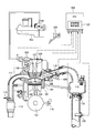
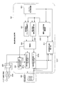
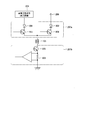
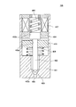
- FIG. 1 is an overall configuration diagram showing a basic configuration example of an internal combustion engine equipped with a fuel injection control device according to an embodiment of the present invention. It is a schematic block diagram which shows the fuel-injection control apparatus which concerns on one Embodiment of this invention. It is a figure which shows the structural example of the fuel-injection drive part shown in FIG. It is sectional drawing of the fuel injection valve shown in FIG. It is a figure explaining the drive method of the fuel injection valve shown in FIG.
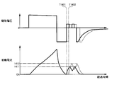
- FIG. 2 is a diagram showing a relationship between a fuel injection pulse width of the fuel injection valve shown in FIG. 1 and a fuel injection amount. It is a figure explaining the detection of the valve closing time and valve opening time which used the drive voltage and drive current in the fuel injection valve shown in FIG.
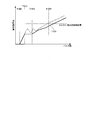
- FIG. 6 is a diagram showing a relationship between a fuel injection pulse width of a fuel injection valve and a fuel injection amount when a correction for delaying a voltage cutoff end timing is performed during half lift control according to an embodiment of the present invention.
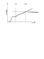
- FIG. 6 is a diagram showing a relationship between a fuel injection pulse width of a fuel injection valve and a fuel injection amount when a correction is made to accelerate an end timing of voltage cutoff during half lift control according to an embodiment of the present invention.
- It is a figure explaining the influence on the injection quantity characteristic at the time of correcting voltage cutoff end timing at the time of half lift control concerning one embodiment of the present invention.
- FIG. 1 is an overall configuration diagram of an internal combustion engine system equipped with a fuel injection control device according to an embodiment.
- An internal combustion engine (engine) 101 shown in FIG. 1 is a four-cycle engine that repeats four strokes of an intake stroke, a compression stroke, a combustion (expansion) stroke, and an exhaust stroke, and is, for example, a multi-cylinder having four cylinders. It is an engine.
- the number of cylinders that the internal combustion engine 101 has is not limited to four, and may have six or eight or more cylinders.
- the internal combustion engine 101 includes a piston 102, an intake valve 103, and an exhaust valve 104.
- the intake air (intake air) to the internal combustion engine 101 passes through an air flow meter (AFM) 120 that detects the amount of inflowing air, and the flow rate is adjusted by a throttle valve 119.
- the air that has passed through the throttle valve 119 is sucked into the collector 115 that is a branch portion, and then enters the combustion chamber 121 of each cylinder via the intake pipe 110 and the intake valve 103 provided for each cylinder. Supplied.
- the fuel is supplied from the fuel tank 123 to the high-pressure fuel pump 125 by the low-pressure fuel pump 124, and is raised to the pressure required for fuel injection by the high-pressure fuel pump 125. That is, the high-pressure fuel pump 125 moves the plunger provided in the high-pressure fuel pump 125 up and down by the power transmitted from the exhaust cam shaft (not shown) of the exhaust cam 128, and the fuel inside the high-pressure fuel pump 125 is moved. Is pressurized (pressurized).
- An opening/closing valve driven by a solenoid is provided at the suction port of the high-pressure fuel pump 125, and the solenoid is connected to a fuel injection control device 127 provided in an ECU (Engine Control Unit) 109.
- the fuel injection control device 127 controls the solenoid based on the control command from the ECU 109, and drives the open/close valve so that the pressure of the fuel discharged from the high-pressure fuel pump 125 (fuel pressure) becomes a desired pressure.
- the fuel whose pressure has been increased by the high-pressure fuel pump 125 is sent to the fuel injection valve 105 via the high-pressure fuel pipe 129.
- the fuel injection valve 105 directly injects fuel into the combustion chamber 121 based on a command from the fuel injection control device 127.
- the fuel injection valve 105 is an electromagnetic valve that operates a valve body to supply fuel by supplying (energizing) a drive current to an electromagnetic coil described later.
- the internal combustion engine 101 is provided with a fuel pressure sensor (fuel pressure sensor) 126 that measures the fuel pressure in the high-pressure fuel pipe 129.
- the ECU 109 sends a control command for setting the fuel pressure in the high-pressure fuel pipe 129 to a desired pressure to the fuel injection control device 127 based on the measurement result of the fuel pressure sensor 126. That is, the ECU 109 performs so-called feedback control to bring the fuel pressure in the high-pressure fuel pipe 129 to a desired pressure.
- each combustion chamber 121 of the internal combustion engine 101 is provided with a spark plug 106, an ignition coil 107, and a water temperature sensor 108.
- the spark plug 106 exposes the electrode portion in the combustion chamber 121, and ignites a mixture of intake air and fuel in the combustion chamber 121 by electric discharge.
- the ignition coil 107 produces a high voltage for discharging at the spark plug 106.
- the water temperature sensor 108 measures the temperature of the cooling water that cools the cylinder of the internal combustion engine 101.
- the ECU 109 controls energization of the ignition coil 107 and ignition control by the ignition plug 106.
- the air-fuel mixture in which the intake air and the fuel are mixed in the combustion chamber 121 is burned by the sparks emitted from the spark plug 106, and the piston 102 is pushed down by this pressure.
- Exhaust gas generated by combustion is discharged to the exhaust pipe 111 via the exhaust valve 104.
- the exhaust pipe 111 is provided with a three-way catalyst 112 and an oxygen sensor 113.
- the three-way catalyst 112 purifies harmful substances such as nitrogen oxides (NOx) contained in the exhaust gas.
- the oxygen sensor 113 detects the oxygen concentration contained in the exhaust gas and outputs the detection result to the ECU 109.
- the ECU 109 performs feedback control based on the detection result of the oxygen sensor 113 so that the fuel injection amount supplied from the fuel injection valve 105 becomes the target air-fuel ratio.
- crankshaft 131 is connected to the piston 102 via a connecting rod 132. Then, the reciprocating motion of the piston 102 is converted into a rotary motion by the crankshaft 131.
- a crank angle sensor 116 is attached to the crankshaft 131. The crank angle sensor 116 detects the rotation and phase of the crankshaft 131 and outputs the detection result to the ECU 109. The ECU 109 can detect the rotation speed of the internal combustion engine 101 based on the output of the crank angle sensor 116.
- Signals from the crank angle sensor 116, the air flow meter 120, the oxygen sensor 113, the accelerator opening sensor 122 indicating the opening of the accelerator operated by the driver, the fuel pressure sensor 126, and the like are input to the ECU 109.
- the ECU 109 calculates the required torque of the internal combustion engine 101 based on the signal supplied from the accelerator opening sensor 122, and determines whether or not it is in an idle state. Further, the ECU 109 calculates the amount of intake air required for the internal combustion engine 101 from the required torque and the like, and outputs an opening signal corresponding to it to the throttle valve 119.
- the ECU 109 also has a rotation speed detection unit that calculates the rotation speed of the internal combustion engine 101 (hereinafter referred to as engine rotation speed) based on the signal supplied from the crank angle sensor 116. Further, the ECU 109 determines whether or not the three-way catalyst 112 is warmed up based on the temperature of the cooling water obtained from the water temperature sensor 108, the elapsed time after the start of the internal combustion engine 101, and the like. Have.
- the fuel injection control device 127 calculates a fuel amount according to the intake air amount and outputs a fuel injection signal corresponding to the calculated fuel amount to the fuel injection valve 105. Further, the fuel injection control device 127 outputs an energization signal to the ignition coil 107 and an ignition signal to the spark plug 106.
- FIG. 2 is a schematic configuration diagram showing the fuel injection control device 127.
- FIG. 3 is a diagram illustrating a configuration example of the fuel injection drive unit illustrated in FIG.
- the fuel injection control device 127 includes a fuel injection pulse signal calculation unit 201 as a fuel injection control unit, a fuel injection drive waveform command unit 202, an engine state detection unit 203, and a drive IC 208. Further, the fuel injection control device 127 includes a high voltage generation unit (boosting device) 206, fuel injection drive units 207a and 207b, a valve body operation time detection unit 211, and a drive current correction amount calculation unit 212.
- boosting device boosting device
- the engine state detection unit 203 collects and provides various information such as the engine speed, the intake air amount, the cooling water temperature, the fuel pressure, and the failure state of the internal combustion engine 101.
- the fuel injection pulse signal calculation unit 201 calculates the injection pulse width that defines the fuel injection period of the fuel injection valve 105 based on various information obtained from the engine state detection unit 203, and outputs it to the drive IC 208.
- the fuel injection drive waveform command unit 202 calculates the command value of the drive current supplied to open and maintain the valve of the fuel injection valve 105, and outputs it to the drive IC 208.
- the battery voltage 209 is supplied to the high voltage generation unit 206 via the fuse 204 and the relay 205.
- the high voltage generator 206 generates a high power supply voltage 210 required when the electromagnetic solenoid type fuel injection valve 105 opens based on the battery voltage 209.
- the power supply voltage 210 is referred to as a high voltage 210.
- As a power source of the fuel injection valve 105 there are provided two systems of a high voltage 210 for ensuring the valve opening force of the valve body and a battery voltage 209 for holding the valve open so that the valve body does not close after opening. ing.
- the fuel injection drive unit 207a is provided on the upstream side of the fuel injection valve 105, and supplies the fuel injection valve 105 with a high voltage 210 required to open the fuel injection valve 105.
- the fuel injection drive unit 207a supplies the fuel injection valve 105 with the battery voltage 209 required to maintain the open state of the fuel injection valve 105 after opening the fuel injection valve 105.
- the fuel injection drive unit 207a includes diodes 301 and 302, a high voltage side switching element 303, and a low voltage side switching element 304.
- the fuel injection drive unit 207a supplies the high voltage 210 supplied from the high voltage generation unit 206 to the fuel injection valve 105 using the high voltage side switching element 303 through the diode 301 provided for preventing current backflow. ..
- the fuel injection drive unit 207a supplies the battery voltage 209 supplied via the relay 205 to the fuel injection valve 105 using the low voltage side switching element 304 through the diode 302 provided for preventing current backflow. To do.
- the fuel injection drive unit 207b is provided on the downstream side of the fuel injection valve 105, and has a switching element 305 and a shunt resistor 306.
- the fuel injection drive unit 207b applies the power supplied from the upstream fuel injection drive unit 207a to the fuel injection valve 105 by turning on the switching element 305. Further, the fuel injection drive unit 207b detects the current consumed in the fuel injection valve 105 by the shunt resistor 306.
- the drive IC 208 shown in FIG. 2 controls the fuel injection drive units 207a and 207b based on the injection pulse width calculated by the fuel injection pulse signal calculation unit 201 and the drive current waveform calculated by the fuel injection drive waveform command unit 202. Control. That is, the drive IC 208 controls the high voltage 210 and the battery voltage 209 applied to the fuel injection valve 105, and controls the drive current supplied to the fuel injection valve 105.
- the valve body operation time detection unit 211 detects the valve body operation time of the fuel injection valve 105 and outputs it to the drive current correction amount calculation unit 212.
- the drive current correction amount calculation unit 212 calculates the correction amount of the drive current based on the valve operating time, and outputs it to the fuel injection pulse signal calculation unit 201 and the fuel injection drive waveform command unit 202.
- the drive current correction amount calculation unit 212 and the fuel injection drive waveform command unit 202 represent one specific example of the control unit according to the present invention. The detection of the valve body operation time by the valve body operation time detection unit 211 and the calculation of the drive current correction amount by the drive current correction amount calculation unit 212 will be described in detail later.
- FIG. 4 is a sectional view of the fuel injection valve 105.
- the fuel injection valve 105 is an electromagnetic fuel injection valve including a normally closed solenoid valve.
- the fuel injection valve 105 has a housing 401 forming an outer shell portion, a valve body 402 arranged in the housing 401, a movable core 403, and a fixed core 404.
- a valve seat 405 and an injection hole 406 communicating with the valve seat 405 are formed in the housing 401.
- the valve body 402 is formed in a substantially rod shape, and a tip portion 402a, which is one end, is formed in a substantially conical shape.
- the tip portion 402a of the valve body 402 faces the valve seat 405 of the housing 401.
- the fuel injection valve 105 is closed when the tip portion 402a of the valve body 402 contacts the valve seat 405, and fuel is not injected from the injection hole 406.
- the direction in which the front end portion 402a of the valve body 402 approaches the valve seat 405 is the valve closing direction
- the direction in which the front end portion 402a of the valve body 402 moves away from the valve seat 405 is the valve opening direction.
- the fixed core 404 is formed in a tubular shape, and is fixed to the end of the housing 401 opposite to the valve seat 405.
- the other end (rear end) side of the valve body 402 is inserted into the cylindrical hole of the fixed core 404.
- a solenoid 407 is arranged so as to go around the other end (rear end) side of the valve body 402.
- a set spring 408 that biases the valve body 402 in the valve closing direction is arranged in the cylindrical hole of the fixed core 404.
- One end of the set spring 408 is in contact with the rear end portion 402b which is the other end of the valve body 402, and the other end of the set spring 408 is in contact with the housing 401.
- the movable core 403 is arranged between the fixed core 404 and the valve seat 405, and has a circular through hole 403a through which the valve body 402 penetrates.
- the rear end portion 402b of the valve body 402 has a larger diameter than the through hole 403a of the movable core 403. Therefore, the periphery of the through hole 403a in the movable core 403 faces the periphery of the rear end portion 402b of the valve body 402.
- a zero spring 409 is arranged between the movable core 403 and the housing 401.
- the zero spring 409 biases the movable core 403 in the valve opening direction.
- the movable core 403 is arranged at an initial position set between the fixed core 404 and the valve seat 405 by being biased by the zero spring 409.
- the inside of the housing 401 is filled with fuel.
- the set spring 408 biases the valve body 402 in the valve closing direction, and presses the valve body 402 in the valve closing direction against the biasing force of the zero spring 409.
- the tip portion 402a of the valve body 402 contacts the valve seat 405 and closes the injection hole 406.
- the tip portion 402a of the valve body 402 separates from the valve seat 405, and the injection hole 406 that was blocked by the valve body 402 until then is opened and fuel is injected.
- the movable core 403 After fuel injection, the movable core 403 returns to the initial position due to the balance between the set spring 408 and the zero spring 409.
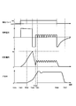
- FIG. 5 is a diagram illustrating a method of driving the fuel injection valve 105.
- FIG. 5 shows, in time series, an example of the injection pulse, the drive voltage, the drive current, and the displacement amount (valve displacement) of the valve body 402 when the fuel is injected from the fuel injection valve 105.
- a current set value described later is set in advance based on the characteristics of the fuel injection valve 105.
- the injection amount characteristic of the fuel injection valve 105 according to the current set value is stored in a memory (for example, RAM (Read Only Memory)) provided in the ECU 109.
- the fuel injection control device 127 calculates the injection pulse of the fuel injection valve 105 from the operating state of the internal combustion engine 101 and the injection amount characteristic of the fuel injection valve 105.
- the injection pulse output from the fuel injection pulse signal calculation unit 201 (see FIG. 2) is in the off state. Therefore, the fuel injection drive units 207a and 207b are turned off, and the drive current does not flow through the fuel injection valve 105. Therefore, the valve body 402 is biased in the valve closing direction by the biasing force of the set spring of the fuel injection valve 105, and the tip end portion 402a of the valve body 402 comes into contact with the valve seat 405 to close the injection hole 406, Fuel is not injected.
- the injection pulse is turned on, and the fuel injection drive unit 207a and the fuel injection drive unit 207b are turned on.
- the high voltage 210 is applied to the solenoid 407, and the drive current flows through the solenoid 407.
- a drive current flows through the solenoid 407, a magnetic flux is generated between the fixed core 404 and the movable core 403, and a magnetic attraction force acts on the movable core 403.
- the valve body 402 moves together with the movable core 403 until the movable core 403 collides with the fixed core 404. Then, when the movable core 403 collides with the fixed core 404, the movable core 403 bounces off by the fixed core 404, and the valve body 402 continues to move in the valve opening direction. After that, when the biasing force of the set spring 408 exceeds the magnetic attraction force, the valve body 402 starts moving in the valve closing direction (hereinafter, referred to as bouncing operation). The bouncing operation of the valve body 402 disturbs the flow rate of the fuel injected from the injection hole 406.
- the switching elements 303, 304, 306 of the fuel injection drive units 207a, 207b are turned off. To do. Then, by supplying a high voltage in the reverse direction, the drive current flowing through the solenoid 407 is rapidly reduced, and the speed (power) of the movable core 403 and the valve body 402 is reduced. Accordingly, the bouncing operation of the valve body 402 can be suppressed.
- the fuel injection drive unit 207b is maintained in the ON state, and the fuel injection drive unit 207a is intermittently turned on. That is, by controlling the fuel injection drive unit 207a by PMW (Pulse Width Modulation) and intermittently setting the drive voltage applied to the solenoid 407 to the battery voltage 209, the drive current flowing in the solenoid 407 falls within a predetermined range. To do so. As a result, a magnetic attraction force of a magnitude necessary to draw the movable core 403 toward the fixed core 404 is generated.
- PMW Pulse Width Modulation
- the injection pulse is turned off.
- the fuel injection drive units 207a and 207b are all turned off, the drive voltage applied to the solenoid 407 decreases, and the drive current flowing in the solenoid 407 decreases.
- the magnetic flux generated between the fixed core 404 and the movable core 403 gradually disappears, and the magnetic attraction force acting on the movable core 403 disappears.
- the valve body 402 When the magnetic attraction force acting on the movable core 403 disappears, the valve body 402 is pushed back in the valve closing direction with a predetermined time delay due to the biasing force of the set spring 408 and the pressing force of the fuel pressure (fuel pressure). Then, at time T507, the valve body 402 is returned to the original position. That is, the tip portion 402a of the valve body 402 contacts the valve seat 405, and the fuel injection valve 105 is closed. As a result, fuel is not injected from the injection hole 406.
- FIG. 6 is a diagram showing the relationship between the fuel injection pulse width of the fuel injection valve 105 and the fuel injection amount, in which the horizontal axis represents the injection pulse width and the vertical axis represents the fuel injection amount per hour.
- the period from the time T502 when the valve body 402 starts to open to the time T505 when the valve body 402 reaches the full lift is based on the peak current supply time by the high voltage application. Since the lift amount of the fuel injection amount increases, the fuel injection amount increases.
- the gradient of the fuel injection amount (fuel injection amount increase rate from T502 to T505) in this period is determined according to the valve opening speed of the valve body 402. As described above, since the peak current supply source is the high voltage 210, the gradient of the fuel injection amount becomes steep.
- This bouncing operation period is generally not used as a period for performing fuel injection because of large variations in characteristics among fuel injection valves and poor reproducibility for each injection operation. That is, the injection pulse is not set during the bouncing operation period.
- valve body 402 after T601 where the bouncing has converged maintains the full lift position, so that the fuel injection amount has an increasing characteristic of an inclination proportional to the length of the injection pulse.
- FIG. 7 is a diagram illustrating detection of the valve closing time and the valve opening time using the drive voltage and the drive current in the fuel injection valve 105.
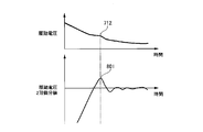
- FIG. 8 is a diagram illustrating a method of detecting an inflection point of a drive voltage in the fuel injection valve 105.
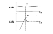
- FIG. 9 is a diagram illustrating a method of detecting an inflection point of a drive current in the fuel injection valve 105.
- the valve body operating time of the fuel injection valve 105 is the valve opening time 713 from a certain reference point (time T701) to completion of valve opening (time T704), or a certain reference point (time T706). ) Until the valve closing is completed (time T707) is defined as the valve closing time 714.
- the high voltage 210 is applied to the solenoid 407, a relatively large drive current flows, and the movable core 403 and the valve body 402 are separated from each other. Be accelerated. Then, the high voltage 210 applied to the solenoid 407 is cut off, and the drive current flowing through the solenoid 407 decreases to a predetermined value.
- the movable core 403 collides with the fixed core 404 in a state where the drive current flowing in the solenoid 407 is stable.
- the acceleration of the movable core 403 changes and the inductance of the solenoid 407 changes.
- the change in the inductance of the solenoid 407 appears as an inflection point in the drive current flowing in the solenoid 407 or the drive voltage applied to the solenoid 407.
- the drive voltage is maintained substantially constant, so that the inflection point does not appear in the drive voltage but appears in the drive current (inflection point 711).
- the inductance of the solenoid 407 changes. That is, when the fuel injection valve 105 is closed, the drive current flowing through the solenoid 407 is shut off and the counter electromotive force is applied to the solenoid 407. Then, when the drive current converges, the back electromotive force also gradually decreases, so that the inductance changes when the back electromotive force decreases, so that an inflection point occurs in the drive voltage (inflection point 712).
- the inflection point 711 of the drive current which appears when the fuel injection valve 105 is opened as described above, is the opening timing of the fuel injection valve 105. Therefore, the valve opening time 713 can be detected by measuring the time from the timing when the injection pulse is turned on to the inflection point 711 of the drive current.
- the inflection point 712 of the drive voltage that appears when the fuel injection valve 105 is closed is the valve closing timing of the fuel injection valve 105. Therefore, the valve closing time 714 can be detected by measuring the time from the timing when the injection pulse is turned off to the inflection point 712 of the drive voltage.
- the inflection point 711 appears as an extreme value (a maximum value or a minimum value) when the time-series data of the drive current flowing in the solenoid 407 is differentiated by the second order.
- the inflection point 712 appears as an extreme value (a maximum value or a minimum value) when the time-series data of the driving voltage applied to the solenoid 407 is subjected to the second-order differentiation. Therefore, the inflection points 712 and 713 can be specified by detecting the extreme value of the time series data of the drive current or the drive voltage.
- FIG. 8 shows time series data of the drive voltage and the second-order differential value thereof during the valve closing operation of the fuel injection valve 105.
- the driving voltage shown in FIG. 8 is shown by reversing the positive and negative values with respect to FIGS.
- Reference numeral 801 shown in FIG. 8 is an extreme value corresponding to the inflection point 712.
- FIG. 9 shows time series data of the drive current and the second-order differential value thereof during the valve opening operation of the fuel injection valve 105.
- 901 shown in FIG. 9 is an extreme value corresponding to the inflection point 711.
- the S/N ratio of the drive current or the drive voltage is low and the noise level thereof is high, it becomes difficult to detect the extreme value from the result of the second-order differentiation of the time series data of the drive current or the drive voltage. Therefore, a desired extreme value can be detected by applying a low-pass filter or the like to the drive current or drive voltage and performing second-order differentiation on the smoothed time series data.
- the second-order differential value of the drive voltage shown in FIG. 8 is obtained by filtering the drive voltage and performing second-order differentiation on the smoothed data.
- the second-order differential value of the drive current shown in FIG. 9 is obtained by performing a second-order differentiation on the smoothed data by filtering the drive current.
- the time-series data of the drive current to be subjected to the second-order differentiation be time-series data of the drive current after the ejection pulse is in the ON state (in other words, after the drive voltage or the drive current is turned on) and a certain time has elapsed. .. That is, it is desirable that the time-series data of the drive current to which the second-order differentiation is applied be the time-series data of the drive current after switching from the high voltage 210 to the battery voltage 209.
- the time-series data of the drive voltage to be subjected to the second-order differentiation be time-series data of the drive voltage after the ejection pulse is in the off state (in other words, after the drive voltage or the drive current is turned off) and a certain time has elapsed. .. That is, it is desirable that the time-series data of the drive voltage to be subjected to the second-order differentiation be the time-series data of the drive voltage after the application of the counter electromotive force after the drive voltage is turned off.
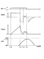
- FIG. 10 is a diagram illustrating a method of driving the fuel injection valve 105 during the half lift control.
- the half-lift control is to turn off the injection pulse during a period from the start of the valve opening operation of the fuel injection valve 105 until reaching the full lift (the period from time T502 to time T505 shown in FIG. 5). Therefore, the behavior of the valve body 402 is defined as control that operates so as to draw a parabola. However, when the injection pulse is turned off at T502, fuel is not injected.
- the high voltage 210 is applied to the solenoid 407, and the valve opening peak current flows.
- the movable core 403 is displaced in the valve opening direction by the magnetic attraction force acting on the movable core 403, and performs idling operation.
- the movable core 403 contacts the rear end portion 402b of the valve body 402, the valve body 402 starts to be displaced, and the fuel is injected from the injection hole 406.
- the fuel injection drive units 207a and 207b are turned off (time T1002), and the high voltage 210 is applied in the negative direction to rapidly reduce the current value. Due to this voltage interruption, the current flowing through the solenoid 407 decreases, the magnetic attraction force acting on the movable core 403 decreases, and the kinetic energy of the valve body 402 decreases. As a result, the moving speed of the valve body 402 (valve opening speed of the fuel injection valve 105) is suppressed.
- the holding current is supplied by applying a low voltage such as the battery voltage 209, so that the magnetic attraction force starts increasing again and the valve body 402 is accelerated (time T1003).
- the injection pulse is turned off.
- the fuel injection valve 105 starts the valve closing operation before the valve body 402 reaches the full lift position, and eventually closes the valve.
- the amount of increase in the lift amount after the voltage is cut off can be controlled by the length of the holding current flowing time (holding current supply time) or the size of the holding current. Therefore, it is possible to make the valve element 402 reach the full lift position and inject fuel by increasing the holding current supply time or increasing the holding current. By performing the half lift control in this manner, it becomes possible to continuously increase the lift amount to the full lift position without causing the bowing while providing a gentle valve opening operation.
- FIG. 11 is a diagram showing injection amount characteristics when the half lift control shown in FIG. 10 is performed.
- the injection amount characteristic shown by the broken line in FIG. 11 is the injection amount characteristic shown in FIG. 6 (the injection amount characteristic when the driving method of the fuel injection valve 105 shown in FIG. 5 is carried out).
- the injection amount characteristic 1101 rises from time T1001 when the fuel injection valve 105 starts the valve opening operation to time T1002 when the peak current is reached. Then, at time T1002, the voltage is cut off.
- the injection amount characteristic 1101 becomes flat until time T1003, which is the timing at which the voltage cutoff ends, and then the application of the low voltage starts, so that the injection amount characteristic starts to rise again.
- the drive current correction amount calculation unit 212 calculates the correction amount of the drive current. Then, by correcting the drive current based on the calculation result of the drive current correction amount calculation unit 212, the injection amount characteristics are made uniform and the injection amount variation is reduced. Specifically, the correction of the drive current can be realized by correcting the boosted voltage application time and the voltage cutoff start timing or end timing. Further, it can be realized by correcting the holding current or the holding current supply period.
- FIG. 12 is a diagram illustrating voltage and current control during half lift control.
- the solid line shown in FIG. 12 is an example of various waveforms of the reference (predetermined) fuel injection valve. Further, the dotted line shown in FIG. 12 is an example of various waveforms of the fuel injection valve in which the spring force of the set spring 408 is relatively strong, and the broken line is various waveforms of the fuel injection valve in which the spring force of the set spring 408 is relatively weak. It is an example of a waveform.
- the boost voltage application time is determined based on the valve closing time or valve opening time, which indirectly detects the variation of the fuel injection valve.
- the boosted voltage application time is set shorter than the time for the movable core 403 to reach (contact) the fixed core 404 in order to prevent bouncing due to an excessive valve opening force.
- the boost voltage application time needs to be longer than the period corresponding to the current value that can reliably open the valve (minimum guaranteed current value that can be opened) even under the maximum fuel pressure at which the fuel injection valve is used. That is, the boosted voltage application time is a time at which the minimum required magnetic attraction force for the valve opening operation of the fuel injection valve is generated and the opening of the fuel injection valve can be guaranteed.
- the reference (predetermined) fuel injection valve is the fuel injection valve 105P.
- a fuel injection valve having a stronger spring force of the set spring 408 than the fuel injection valve 105P is referred to as a fuel injection valve 105S, and a fuel injection valve having a relatively weaker spring force of the set spring 408 than the fuel injection valve 105P is used.
- the fuel injection valve 105W is a fuel injection valve having a stronger spring force of the set spring 408 than the fuel injection valve 105P.
- the fuel injection valve 105S has a shorter valve closing time and a longer valve opening time than the fuel injection valve 105P.
- the boosting voltage application time 1213 of the fuel injection valve 105S is longer than the boosting voltage application time 1212 of the fuel injection valve 105P. That is, the timing at which the drive voltage of the fuel injection valve 105S is cut off is set to be later than the timing at which the drive voltage of the fuel injection valve 105P is cut off.
- the value of the drive current flowing through the solenoid 407 of the fuel injection valve 105S becomes larger than the value of the drive current flowing through the solenoid 407 of the fuel injection valve 105P.
- the magnetic attraction force acting on the movable core 403 of the fuel injection valve 105S becomes larger than the magnetic attraction force acting on the movable core 403 of the fuel injection valve 105P. Therefore, the opening time of the fuel injection valve 105S can be shortened to approach the opening time of the fuel injection valve 105P.
- the fuel injection valve 105W has a longer valve closing time and a shorter valve opening time than the fuel injection valve 105P.
- the boost voltage application time 1211 of the fuel injection valve 105W is shorter than the boost voltage application time 1212 of the fuel injection valve 105P. That is, the timing at which the drive voltage of the fuel injection valve 105W is cut off is set earlier than the timing at which the drive voltage of the fuel injection valve 105P is cut off.
- the value of the drive current flowing through the solenoid 407 of the fuel injection valve 105W becomes smaller than the value of the drive current flowing through the solenoid 407 of the fuel injection valve 105P.
- the magnetic attraction force acting on the movable core 403 of the fuel injection valve 105W becomes smaller than the magnetic attraction force acting on the movable core 403 of the fuel injection valve 105P. Therefore, the valve opening time of the fuel injection valve 105W can be lengthened to approach the valve opening time of the fuel injection valve 105P.
- the boosting voltage application time As described above, by setting the boosting voltage application time to be longer or shorter than the reference boosting voltage application time 1212 of the fuel injection valve 105P, the magnetic force corresponding to the variation in the machine difference of the fuel injection valves 105P, 105S, 105W can be obtained. By applying suction force, the valve behavior when opening the valve can be made uniform.
- each fuel injection valve 105P, 105S, 105W may be measured in advance, and the boost voltage application time correction amount may be calculated based on the valve closing time or the valve opening time.
- the boost voltage application time correction amount may be calculated based on the valve closing time or the valve opening time.
- the boost voltage application time can be corrected according to the deterioration over time, and variations in the injection amount can be reduced.
- FIG. 13 shows the injection amount characteristics when the boost voltage application time is changed for each fuel injection valve.
- the injection characteristic of the fuel injection valve 105S in which the spring force of the set spring 408 is relatively strong is shown in practice, and the injection characteristic of the fuel injection valve 105W in which the spring force of the set spring 408 is relatively weak is shown by a dotted line. There is.
- the magnetic attraction force generated in the solenoid 407 has decreased. However, by supplying a current with a low voltage thereafter, the magnetic attraction force increases, and the rising speed of the valve body 402 increases. At this time, the time required for the magnetic attraction force generated in the solenoid 407 to become larger than the spring force of the set spring 408 is slower as the spring force of the set spring 408 is larger, and is faster as the spring force of the set spring 408 is smaller. .. That is, the larger the spring force of the set spring 408, the smaller the injection amount after time T1301, and the smaller the spring force of the set spring 408, the larger the injection amount after time T1301. As a result, the injection amount varies.
- the magnetic attraction force acting on the valve body 402 in the half lift region may be changed according to the valve closing time or the valve opening time affected by the spring force of the set spring 408. Good.
- the voltage cutoff end timing or the voltage cutoff start timing after applying the boosted voltage, and the holding current or the low voltage application time (holding current supply period) may be changed.
- the magnetic attraction force of the fuel injection valve where the spring force of the set spring 408 is relatively weak with the magnetic attraction force of the fuel injection valve where the spring force of the set spring 408 is relatively strong the magnetic attraction force is suppressed. Correct so that it becomes (decrease). Further, in order to match the magnetic attraction force of the fuel injection valve in which the spring force of the set spring 408 is relatively strong with the magnetic attraction force of the fuel injection valve in which the spring force of the set spring 408 is relatively weak, the magnetic attraction force is large. Correct so that
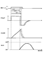
- FIG. 14 is a diagram illustrating a method of correcting the voltage cutoff end timing during the half lift control.
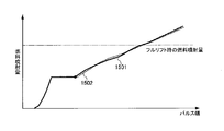
- FIG. 15 is a diagram showing the relationship between the fuel injection pulse width of the fuel injection valve and the fuel injection amount when the correction for delaying the voltage cutoff end timing is performed during the half lift control.
- FIG. 16 is a diagram showing the relationship between the fuel injection pulse width of the fuel injection valve and the fuel injection amount when the correction for advancing the voltage cutoff end timing in the half lift control is performed.
- the voltage cutoff end timing (time T1402) of the fuel injection valve having a long valve close time and a short valve open time is set to the voltage cutoff end of the fuel injection valve having a short valve close time and a long valve open time. It is relatively delayed from the timing (time T1401). Accordingly, the rising speed of the valve body 402 of the fuel injection valve having a long valve closing time and a short valve opening time can be relatively reduced, and the rising of the magnetic attraction force due to the holding current can be delayed.
- the timing at which the valve body 402 is re-accelerated in the valve opening direction can be delayed, and the injection amount characteristic of the fuel injection valve having a long valve closing time and a short valve opening time can be obtained by comparing The injection amount characteristic of the fuel injection valve having a long valve time can be approximated.
- the holding current 1412 when the voltage cutoff end timing is delayed, the holding current 1412 thereafter is set to a value larger than the holding current 1411 of the fuel injection valve whose valve closing time is short and whose valve opening time is long, The rise of the valve body 402 (movement in the valve opening direction) is promoted.
- the holding current is set small in order to reduce the magnetic attraction force.
- the voltage cutoff end timing is delayed, if the holding current is reduced, the rising speed of the valve body 402 becomes too slow, and the injection amount characteristic shown in FIG. 15 is projected downward (below the solid line). turn into.
- the value of the holding current 1412 of the fuel injection valve whose valve closing time is long and whose valve opening time is short as described above is larger than the value of the holding current 1411 of the fuel injection valve whose valve closing time is short and whose valve opening time is long. Enlarge. As a result, it is possible to promote the upward movement (movement in the valve opening direction) of the valve body 402 in the fuel injection valve having a long valve closing time and a short valve opening time, and prevent the rising speed from becoming too slow.
- the injection amount characteristic 1502 in the half-lift region of the fuel injection valve having a long valve closing time and a short valve opening time is compared with that of a fuel injection valve having a short valve closing time and a long valve closing time.
- the injection amount characteristic 1501 in the half lift region can be made closer. As a result, it is possible to reduce the variation in the injection amount and improve the linearity of the injection amount characteristic, so that the controllability of the fuel injection valve is improved.
- the voltage cutoff end timing of the fuel injection valve whose valve closing time is short and whose valve opening time is long is set relatively earlier than the voltage cutoff ending timing of the fuel injection valve whose valve closing time is long and whose valve opening time is short. May be.
- the rising speed of the valve body 402 of the fuel injection valve having a short valve closing time and a long valve opening time can be relatively increased, and the rising of the magnetic attraction force by the holding current can be accelerated.
- the timing at which the valve body 402 is re-accelerated in the valve opening direction can be accelerated, and the injection amount characteristic of the fuel injection valve having a short valve closing time and a long valve opening time can be obtained by using The injection amount characteristic of the fuel injection valve having a short valve time can be approximated.
- the voltage cutoff end timing is corrected in this way, since the rising speed of the valve body 402 is increased, the injection amount is increased in the half lift region. Therefore, when the voltage cutoff end timing is advanced, the holding current after that is set to be smaller than the holding current of the fuel injection valve that has a long valve closing time and a short valve opening time, and the valve body 402 rises (valve opening direction). To move).
- the injection amount characteristic 1601 in the half-lift region of the fuel injection valve whose valve closing time is short and whose valve opening time is long is compared with that of a fuel injection valve whose valve closing time is long and valve opening time is short.
- the injection amount characteristic 1602 in the half lift region can be adjusted (closer). As a result, it becomes possible to reduce variations in the injection amount.
- performing the above-described correction for changing the voltage cutoff end timing also makes a correction for changing the time during which the high voltage 202 and the battery voltage 209 are cut off with respect to the solenoid 407 of the fuel injection valve.
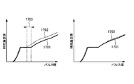
- FIG. 17 is a diagram illustrating the influence on the injection amount characteristic when the voltage cutoff end timing is corrected during the half lift control.
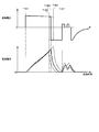
- FIG. 18 is a diagram illustrating a method of correcting the voltage cutoff start timing during the half lift control.
- the flat part of the injection quantity characteristic is caused by voltage interruption. This is because the injection amount does not change during this period because all the switch parts are off even when the injection pulse is turned off during the voltage cutoff. Therefore, by changing the voltage cutoff end timing, the timing at which the flow rate increases from the flow rate flat portion changes.
- the injection amount characteristic 1702 of the fuel injection valve whose voltage cutoff end timing is early has an offset 1703 with respect to the injection amount characteristic 1701 of the fuel injection valve whose voltage cutoff end timing is late. ..
- the generated offset 1703 depends on the change amount of the voltage cutoff end timing, it is possible to match the injection amount by reflecting the change amount of the voltage cutoff end timing on the injection pulse. However, as shown in the right diagram of FIG. 17, it is possible to match the injection amount with the injection pulse width by making the voltage cutoff end timings the same.
- the voltage cutoff start timing (time T1801, time T1802, time T1802, time T1802) is set to the same voltage cutoff end timing (time T1811) of a plurality of fuel injection valves having different valve closing times (valve opening times). T1803) is changed for each fuel injection valve.
- Time T1801 is the voltage cutoff start timing of the fuel injection valve in which the spring force of the set spring 408 is relatively weak.
- Time T1802 is the voltage cutoff start timing of the fuel injection valve in which the spring force of the set spring 408 is relatively strong with respect to the fuel injection valve whose voltage cutoff start timing is time T1801.
- time T1803 is the voltage cutoff timing of the fuel injection valve in which the spring force of the set spring 408 is relatively strong with respect to the fuel injection valve whose voltage cutoff start timing is time T1802.
- the fuel injection valve whose voltage cutoff start timing is time T1801 has a longer valve closing time and a shorter valve open time than the fuel injection valves whose voltage cutoff start timing is times T1802 and T1803. Further, the fuel injection valve whose voltage cutoff start timing is time T1802 has a longer valve closing time and shorter valve open time than the fuel injection valve whose voltage cutoff start timing is time T1803.
- the reference (predetermined) fuel injection valve is set to the fuel injection valve with the strongest spring force of the set spring 408 (the voltage cutoff start timing is the time). (T1803 fuel injection valve). Thereby, the linearity of the injection amount characteristic can be secured.
- the reference fuel injection valve may be the fuel injection valve having the strongest spring force of the set spring 408 (the fuel injection valve whose voltage cutoff start timing is time T1801). In this case, the linearity of the injection amount characteristic is disturbed as compared with the case where the fuel injection valve having the strongest spring force of the set spring 408 is used as the reference fuel injection valve, but the injection amount characteristics of the plurality of fuel injection valves are made uniform. You can
- the voltage cutoff end timing (time T1811) of the three fuel injection valves is set to the voltage cutoff end of the fuel injection valve (the voltage cutoff start timing is time T1802) in which the spring force of the set spring 408 is at the center. Aligned with the timing. That is, the reference fuel injection valve was the fuel injection valve in which the spring force of the set spring 408 was at the center (voltage cutoff start timing was time T1802).
- the voltage cutoff start timing of the fuel injection valve having a relatively short valve closing time and a long valve opening time was corrected to be earlier, and time T1801 was determined. Further, with reference to the voltage cutoff start timing at time T1802, the voltage cutoff start timing of the fuel injection valve having a relatively long valve closing time and a short valve opening time is corrected to be delayed, and time T1803 is determined.
- the ascending speed of the valve body 402 for the fuel injection valve in which the spring force of the set spring 408 is relatively weak It is possible to prevent the (valve opening speed) from becoming excessive. Further, for the fuel injection valve in which the spring force of the set spring 408 is relatively strong, the rising speed (valve opening speed) of the valve body 402 can be prevented from being suppressed too much.
- the injection amount characteristic of the fuel injection valve in which the spring force of the set spring 408 is relatively weak can be brought close to the reference injection amount characteristic of the fuel injection valve.
- the fuel injection valve in which the spring force of the set spring 408 is relatively weak has a longer valve closing time and a shorter valve opening time than the reference fuel injection valve. Therefore, the injection amount characteristic in the half-lift region of the fuel injection valve whose valve closing time is long and whose valve opening time is short is made close to the injection amount characteristic in the half-lift region of the fuel injection valve whose valve closing time is short and whose valve opening time is long. )be able to.
- the injection amount characteristic of the fuel injection valve in which the spring force of the set spring 408 is relatively strong can be made close to the injection amount characteristic of the fuel injection valve as the reference.
- the fuel injection valve in which the spring force of the set spring 408 is relatively strong has a shorter valve closing time and a longer valve opening time than the reference fuel injection valve. Therefore, the injection amount characteristic in the half-lift region of the fuel injection valve whose valve closing time is short and whose valve opening time is long is made close to the injection amount characteristic in the half-lift region of the fuel injection valve whose valve closing time is long and whose valve opening time is short. )be able to. As a result, it is possible to reduce variations in the injection amounts of the three fuel injection valves.
- the boosted voltage supply time can be corrected by correcting the voltage cutoff start timing. Therefore, the period from the timing at which the injection pulse is turned on (time T1821) to the voltage cutoff end timing (time T1811) may be used as the period for performing fuel injection.
- the boosted voltage supply time, the voltage cutoff end timing or the voltage cutoff start timing, and the holding current described above can be changed according to the fuel pressure value applied to the fuel injection valve 105. Since the fuel pressure acts as a force that pushes the valve body 402 in the valve closing direction, the higher the fuel pressure, the stronger the force that urges the valve body 402 in the valve closing direction. Therefore, by replacing the spring force of the set spring 408 described above with the fuel pressure value, the boost voltage supply time, the voltage cutoff end timing or the pressure cutoff start timing, and the holding current can be corrected with respect to the fuel pressure value.
- a fuel injection valve whose fuel pressure value is smaller than a predetermined value has a longer closing time and a shorter opening time than a fuel injection valve whose fuel pressure value is a predetermined value. Therefore, the voltage cutoff end timing of the fuel injection valve whose fuel pressure value is smaller than the predetermined value is made later than the voltage cutoff end timing of the fuel injection valve whose fuel pressure value is the predetermined value (the same drive voltage and drive voltage as in FIG. 14). Become a dragon).
- the holding current of the fuel injection valve whose fuel pressure value is smaller than the predetermined value is set to a value larger than the holding current of the fuel injection valve whose fuel pressure value is the predetermined value, and the valve body 402 is raised (in the valve opening direction). Move)).
- the valve body 402 is raised (in the valve opening direction).
- the injection amount characteristic of the fuel injection valve whose fuel pressure value is smaller than the predetermined value can be matched (closer) to the injection amount characteristic of the fuel injection valve whose closed fuel pressure value is the predetermined value (similar to FIG. 15). It becomes the injection quantity characteristic).
- the coils of the plurality of fuel injection valves (fuel injection valves 105) having the coils (solenoid 407) for energization are provided.
- a control unit fuel injection drive waveform command unit 202) that controls the applied voltage is provided.
- the control unit controls to cut off the voltage (high voltage 210) being applied to the coil.
- the control unit starts timing of voltage cutoff to the coil of at least one fuel injection valve (voltage cutoff start) based on the valve closing time (valve closing time 714) or the valve opening time (valve opening time 713).
- injection amount characteristic 1502 injection amount characteristic 1502 of at least one fuel injection valve and match it with the injection amount characteristic (injection amount characteristic 1501) of another fuel injection valve (see FIG. 15). ..
- injection amount characteristic 1501 injection amount characteristic 1501 of another fuel injection valve
- the control unit of the fuel injection control device sets the timing (time T1402) at which the closing time of the voltage to the coil of the fuel injection valve, which is longer than the predetermined closing time, is ended as the closing time.
- the timing is set to be later than the timing (time T1401) at which the cutoff of the voltage to the coil of the fuel injection valve is completed for a predetermined time (see FIG. 14).
- the timing (time T1402) at which the cutoff of the voltage to the coil of the fuel injection valve whose valve opening time is shorter than the specific time is ended is finished at the timing (time T1402). It is later than the timing (time T1401).
- the control unit of the fuel injection control device changes the magnitude of the holding current flowing by applying a low voltage lower than the voltage to the coil after the voltage is cut off. That is, the value of the holding current (holding current 1412) flowing in the coil of the fuel injection valve whose valve closing time is longer than the predetermined time is calculated as the holding current (holding current 1411) flowing in the coil of the fuel injection valve whose valve closing time is the predetermined time. ) Value (see FIG. 14). In other words, the value of the holding current (holding current 1412) flowing through the coil of the fuel injection valve whose valve opening time is shorter than the specific time is calculated as the holding current (holding current flowing through the coil of the fuel injection valve whose closing time is the specific time). 1411).
- the injection amount characteristic (injection amount characteristic 1502) of the fuel injection valve having a long valve closing time and a short valve opening time is compared with the injection amount characteristic (injection amount characteristic of a fuel injection valve having a short valve closing time and a long valve closing time). 1501) more closely (see FIG. 15).
- control unit of the fuel injection control device sets the timing (time T1803) at which the valve closing time is started to shut off the voltage to the coil of the fuel injection valve to be longer than the predetermined time.
- the timing is set to be later than the timing (time T1802) at which the cutoff of the voltage to the coil of the fuel injection valve is started for a predetermined time.
- time T1811 the timing at which the cutoff of the voltage to the coil of the fuel injection valve whose valve closing time is longer than the predetermined time is ended.
- the cutoff of the voltage to the coil of the fuel injection valve whose valve closing time is the predetermined time is ended.
- the timing is the same as the time (time T1811).
- the timing (time T1803) at which the voltage of the coil of the fuel injection valve whose opening time is shorter than the specific time is started is cut off (time T1803). It is later than the timing (time T1802). Then, at the timing (time T1811) at which the cutoff of the voltage to the coil of the fuel injection valve whose valve opening time is shorter than the specific time is ended, the cutoff of the voltage to the coil of the fuel injection valve whose valve opening time is the specified time is ended.
- the timing is the same as the time (time T1811).
- control unit of the fuel injection control device sets the timing at which the shutoff of the voltage to the coil of the fuel injection valve, which is shorter than the predetermined closing time, is ended, the closing time is the predetermined time. It is set earlier than the timing at which the cutoff of the voltage to the coil of the fuel injection valve is completed. In other words, the timing at which the cutoff of the voltage to the coil of the fuel injection valve whose valve opening time is longer than the specific time is ended is more than the timing at which the cutoff of the voltage to the coil of the fuel injection valve whose valve opening time is the specified time is ended. Make it faster
- control unit of the fuel injection control device changes the magnitude of the holding current that flows when a low voltage lower than the voltage is applied to the coil after the voltage is cut off. That is, the value of the holding current flowing through the coil of the fuel injection valve whose valve opening time is shorter than the predetermined time is made smaller than the value of the holding current flowing through the coil of the fuel injection valve whose valve closing time is the predetermined time.
- injection amount characteristic 1601 of the fuel injection valve having a short valve closing time and a long valve opening time is compared with the injection amount characteristic of the fuel injection valve having a long valve closing time and a short valve opening time (injection amount characteristic). 1602) more closely (see FIG. 16).
- control unit of the fuel injection control device sets the timing (time T1801) at which the valve closing time is started to cut off the voltage to the coil of the fuel injection valve, which is shorter than the predetermined time.
- the timing is set earlier than the timing (time T1802) at which the cutoff of the voltage to the coil of the fuel injection valve is started for a predetermined time.
- time T1811 the timing at which the cutoff of the voltage to the coil of the fuel injection valve whose valve closing time is shorter than the predetermined time is ended.
- the timing is the same as the time (time T1811).
- the timing (time T1801) at which the cutoff of the voltage to the coil of the fuel injection valve whose valve opening time is longer than the specific time is started is started at the timing (time T1801). It is earlier than the timing (time T1802). Then, at the timing (time T1811) at which the cutoff of the voltage to the coil of the fuel injection valve whose valve opening time is longer than the specific time is ended (time T1811), the cutoff of the voltage to the coil of the fuel injection valve whose valve opening time is the specified time is ended.
- the timing is the same as the time (time T1811).
- the injection amount characteristic of the fuel injection valve whose valve closing time is short and whose valve opening time is long can be compared with the characteristic that the valve closing time is long and the valve opening time is short. It is possible to approach the injection amount characteristic of the fuel injection valve (for a specific time). As a result, it is possible to reduce variations in the injection amount of the plurality of fuel injection valves.
- control unit of the fuel injection control device changes the voltage application time or the current value flowing by applying the voltage according to the timing of starting the voltage cutoff.
- the application time of the high voltage 210 is increased so as to shorten the valve opening time.
- the value of the current flowing through the solenoid 407 can be increased.
- the magnetic attraction force acting on the movable core 403 becomes large, and the fuel injection valve whose opening time is shorter than the reference fuel injection valve and whose opening time is longer than the reference fuel injection valve is used as the reference.
- the valve opening time can be approached.
- control unit of the fuel injection control device changes the magnitude of the holding current that flows when a low voltage lower than the voltage is applied to the coil after the voltage is cut off. That is, the timing of ending the cutoff of the voltage to the coil of the fuel injection valve whose fuel pressure value is smaller than the predetermined value is delayed from the timing of ending the cutoff of the voltage to the coil of the fuel injection valve whose fuel pressure value is the predetermined value. Then, the value of the holding current flowing to the coil of the fuel injection valve whose fuel pressure value is smaller than the predetermined value is made larger than the value of the holding current flowing to the coil of the fuel injection valve whose fuel pressure value is the predetermined value.
- the rise of the magnetic attraction force due to the holding current is delayed so that the injection amount characteristic of the fuel injection valve whose fuel pressure value is smaller than the predetermined value is set to a predetermined value. It is possible to approach the injection amount characteristic of the fuel injection valve, which is the value. Further, the rising speed of the valve body 402 in the fuel injection valve whose fuel pressure value is smaller than the predetermined value can be prevented from becoming too slow. As a result, the injection amount characteristic of the fuel injection valve whose fuel pressure value is smaller than the predetermined value can be matched (closer) to the injection amount characteristic of the fuel injection valve whose fuel pressure value is the predetermined value.
- the fuel injection control device (fuel injection control device 127) according to the above-described embodiment applies the voltage applied to the coils of the plurality of fuel injection valves (fuel injection valves 105) having the energization coils (solenoid 407).
- a control unit (fuel injection drive waveform command unit 202) for controlling is provided.
- the control unit controls to cut off the voltage (high voltage 210) being applied to the coil.
- the control unit changes the time during which the voltage is cut off to the coil of at least one fuel injection valve based on the valve closing time (valve closing time 714) or the valve opening time (valve opening time 713). ..
- injection amount characteristic 1502 injection amount characteristic 1502 of at least one fuel injection valve and match it with the injection amount characteristic (injection amount characteristic 1501) of another fuel injection valve (see FIG. 15). ..
- injection amount characteristic 1501 injection amount characteristic 1501 of another fuel injection valve
- the fuel injection control device of the present invention has been described, including its function and effect.
- the fuel injection control device of the present invention is not limited to the above embodiment, and various modifications can be made without departing from the scope of the invention described in the claims.
- High pressure fuel pipe 131... Crank shaft, 132... Connecting rod, 201... Fuel injection pulse signal calculation unit, 202... Fuel injection drive waveform command unit, 203... Engine state detection unit, 204... Fuse, 205... Relay, 206... High voltage generation unit, 207a, 207b... Fuel injection drive unit, 208... Drive IC, 209...Battery voltage, 210...High voltage (power supply voltage), 211...Valve operating time detection unit, 212...Drive current correction amount calculation unit, 301,302...Diode, 303...High voltage side switching element, 304... Low-voltage side switching element, 305... switching element, 306... shunt resistance, 401... housing, 402... valve body, 402a...
Landscapes
- Engineering & Computer Science (AREA)
- Physics & Mathematics (AREA)
- Electromagnetism (AREA)
- Chemical & Material Sciences (AREA)
- Combustion & Propulsion (AREA)
- Mechanical Engineering (AREA)
- General Engineering & Computer Science (AREA)
- Power Engineering (AREA)
- Electrical Control Of Air Or Fuel Supplied To Internal-Combustion Engine (AREA)
- Fuel-Injection Apparatus (AREA)
Abstract
複数の燃料噴射弁の噴射量のばらつきを低減することが可能な燃料噴射制御装置を提供する。そのため本発明の燃料噴射制御装置は、通電用のコイルを有する複数の燃料噴射弁のコイルに印加する電圧を制御する制御部を備える。制御部は、コイルへ印加中の電圧を遮断するように制御する。また、燃料噴射弁が閉弁完了するまでの閉弁時間、又は燃料噴射弁が開弁完了するまでの開弁時間に基づいて、少なくとも1つの燃料噴射弁のコイルへの電圧の遮断を開始するタイミング、又は少なくとも1つの燃料噴射弁のコイルへの電圧の遮断を終了するタイミングを変更する。
Description
本発明は、燃料噴射制御装置に関する。
近年、内燃機関の低燃費化と高出力化を同時に達成することが求められている。その達成手段の一つとして、燃料噴射弁のダイナミックレンジの拡大が要求されている。燃料噴射弁のダイナミックレンジの拡大には、従来の静流特性を確保しつつ、動流特性を改善することが必要となる。この動流特性の改善方法としては、ハーフリフト制御による最小噴射量の低減が知られている。
特許文献1には、ハーフリフト制御における噴射量特性をフルリフト時の噴射量特性に近づけることで極小噴射の噴射量ばらつきを低減する電磁式燃料噴射弁の制御装置が開示されている。この電磁式燃料噴射弁の制御装置では、燃料噴射弁への通電を開始するタイミングで昇圧電圧を印加し、弁体の開弁動作に必要な磁気吸引力を発生させる高電圧通電時間と、相対的に小さな電圧を印加する時間を調整することで弁体のリフト量を調整する。これにより、ハーフリフト領域における噴射量特性が、フルリフト領域の噴射量特性に近づく。
しかしながら、特許文献1に開示された電磁式燃料噴射弁の制御装置のハーフリフト制御は、昇圧電圧の印加時間と、低電圧の印加時間を調整するに過ぎなかった。そのため、ハーフリフト領域における噴射量特性の直線性を改善することはできるものの、特に最小噴射量から噴射量が増加する領域における噴射量のばらつきが大きくなってしまう。
本発明の目的は、上記の問題点を考慮し、複数の燃料噴射弁の噴射量のばらつきを低減することが可能な燃料噴射制御装置を提供することにある。
上記課題を解決し、本発明の目的を達成するため、本発明の燃料噴射制御装置は、通電用のコイルを有する複数の燃料噴射弁のコイルに印加する電圧を制御する制御部を備える。制御部は、コイルへ印加中の電圧を遮断するように制御する。そして、燃料噴射弁への通電停止からその燃料噴射弁が閉弁完了するまでの閉弁時間、又は燃料噴射弁への通電開始からその燃料噴射弁が開弁完了するまでの開弁時間に基づいて、少なくとも1つの燃料噴射弁のコイルへの電圧の遮断を開始するタイミング、又は少なくとも1つの燃料噴射弁のコイルへの電圧の遮断を終了するタイミングを変更する。
上記構成の燃料噴射制御装置によれば、各燃料噴射弁の噴射量のばらつきを低減することができる。
なお、上述した以外の課題、構成および効果は、以下の実施形態の説明により明らかにされる。
なお、上述した以外の課題、構成および効果は、以下の実施形態の説明により明らかにされる。
以下、本発明の一実施形態に係る燃料噴射制御装置について説明する。なお、各図において共通の部材には、同一の符号を付している。
[内燃機関システム]
まず、本実施形態による燃料噴射制御装置を搭載する内燃機関システムの構成について説明する。図1は、実施形態に係る燃料噴射制御装置を搭載する内燃機関システムの全体構成図である。
まず、本実施形態による燃料噴射制御装置を搭載する内燃機関システムの構成について説明する。図1は、実施形態に係る燃料噴射制御装置を搭載する内燃機関システムの全体構成図である。
図1に示す内燃機関(エンジン)101は、吸入行程、圧縮行程、燃焼(膨張)行程、排気行程の4行程を繰り返す4サイクルエンジンであり、例えば、4つの気筒(シリンダ)を備えた多気筒エンジンである。なお、内燃機関101が有する気筒の数は、4つに限定されるものではなく、6つ又は8つ以上の気筒を有していてもよい。
内燃機関101は、ピストン102、吸気弁103、排気弁104を備えている。内燃機関101への吸気(吸入空気)は、流入する空気の量を検出する空気流量計(AFM)120を通過して、スロットル弁119により流量が調整される。スロットル弁119を通過した空気は、分岐部であるコレクタ115に吸入され、その後、各気筒(シリンダ)に対して設けられた吸気管110、吸気弁103を介して、各気筒の燃焼室121に供給される。
一方、燃料は、燃料タンク123から低圧燃料ポンプ124によって高圧燃料ポンプ125へ供給され、高圧燃料ポンプ125によって燃料噴射に必要な圧力に高められる。すなわち、高圧燃料ポンプ125は、排気カム128の排気カム軸(不図示)から伝達される動力により、高圧燃料ポンプ125内に設けられたプランジャーを上下に可動し、高圧燃料ポンプ125内の燃料を加圧(昇圧)する。
高圧燃料ポンプ125の吸入口には、ソレノイドにより駆動する開閉バルブが設けられており、ソレノイドは、ECU(Engine Control Unit)109内に設けられた燃料噴射制御装置127に接続されている。燃料噴射制御装置127は、ECU109からの制御指令に基づいて、ソレノイドを制御し、高圧燃料ポンプ125から吐出する燃料の圧力(燃料圧)が所望の圧力になるように開閉バルブを駆動する。
高圧燃料ポンプ125によって昇圧された燃料は、高圧燃料配管129を介して燃料噴射弁105へ送られる。燃料噴射弁105は、燃料噴射制御装置127の指令に基づいて、燃料を燃焼室121へ直接噴射する。この燃料噴射弁105は、後述する電磁コイルに駆動電流が供給(通電)されることにより、弁体を動作させて、燃料噴射を行う電磁式の弁である。
また、内燃機関101には、高圧燃料配管129内の燃料圧力を計測する燃料圧力センサ(燃圧センサ)126が設けられている。ECU109は、燃料圧力センサ126による計測結果に基づいて、高圧燃料配管129内の燃料圧を所望の圧力にするための制御指令を燃料噴射制御装置127へ送る。すなわち、ECU109は、所謂フィードバック制御を行って、高圧燃料配管129内の燃料圧を所望の圧力にする。
さらに、内燃機関101の各燃焼室121には、点火プラグ106と、点火コイル107と、水温センサ108が設けられている。点火プラグ106は、燃焼室121内に電極部を露出させ、燃焼室121内で吸入空気と燃料が混ざった混合気を放電によって引火する。点火コイル107は、点火プラグ106で放電するための高電圧を作り出す。水温センサ108は、内燃機関101の気筒を冷却する冷却水の温度を測定する。
ECU109は、点火コイル107の通電制御と、点火プラグ106による点火制御を行う。燃焼室121内で吸入空気と燃料が混ざった混合気は、点火プラグ106から放たれる火花により燃焼し、この圧力によりピストン102が押し下げられる。
燃焼により生じた排気ガスは、排気弁104を介して排気管111に排出される。そして、排気管111には、三元触媒112と、酸素センサ113が設けられている。三元触媒112は、排気ガス中に含まれる、例えば、窒素酸化物(NOx)等の有害物質を浄化する。酸素センサ113は、排気ガス中に含まれる酸素濃度を検出し、その検出結果をECU109に出力する。ECU109は、酸素センサ113の検出結果に基づいて、燃料噴射弁105から供給される燃料噴射量が目標空燃比となるように、フィードバック制御を行う。
また、ピストン102には、クランクシャフト131がコンロッド132介して接続されている。そして、ピストン102の往復運動がクランクシャフト131により回転運動に変換される。そして、クランクシャフト131には、クランク角度センサ116が取り付けられている。クランク角度センサ116は、クランクシャフト131の回転と位相を検出し、その検出結果をECU109に出力する。ECU109は、クランク角度センサ116の出力に基づいて、内燃機関101の回転速度を検出することができる。
ECU109には、クランク角度センサ116、空気流量計120、酸素センサ113、運転者が操作するアクセルの開度を示すアクセル開度センサ122、燃料圧力センサ126等の信号が入力される。
ECU109は、アクセル開度センサ122から供給された信号に基づいて、内燃機関101の要求トルクを算出するとともに、アイドル状態であるか否かの判定等を行う。また、ECU109は、要求トルクなどから、内燃機関101に必要な吸入空気量を算出して、それに見合った開度信号をスロットル弁119に出力する。
また、ECU109は、クランク角度センサ116から供給された信号に基づいて、内燃機関101の回転速度(以下、エンジン回転数という)を演算する回転数検出部を有する。さらに、ECU109は、水温センサ108から得られる冷却水の温度と、内燃機関101の始動後の経過時間等から三元触媒112が暖機された状態であるか否かを判断する暖機判断部を有する。
燃料噴射制御装置127は、吸入空気量に応じた燃料量を算出して、それに応じた燃料噴射信号を燃料噴射弁105に出力する。さらに、燃料噴射制御装置127は、点火コイル107に通電信号を出力し、点火プラグ106に点火信号を出力する。
[燃料噴射制御装置の構成]
次に、図1に示す燃料噴射制御装置127の構成について、図2と図3を用いて説明する。
図2は、燃料噴射制御装置127を示す概略構成図である。図3は、図2に示す燃料噴射駆動部の構成例を示す図である。
次に、図1に示す燃料噴射制御装置127の構成について、図2と図3を用いて説明する。
図2は、燃料噴射制御装置127を示す概略構成図である。図3は、図2に示す燃料噴射駆動部の構成例を示す図である。
図2に示すように、燃料噴射制御装置127は、燃料噴射制御部としての燃料噴射パルス信号演算部201及び燃料噴射駆動波形指令部202と、エンジン状態検知部203と、駆動IC208とを備える。また、燃料噴射制御装置127は、高電圧生成部(昇圧装置)206、燃料噴射駆動部207a,207b、弁体動作時間検出部211、駆動電流補正量演算部212を備える。
エンジン状態検知部203は、前述のエンジン回転数、吸入空気量、冷却水温度、燃料圧力や内燃機関101の故障状態などの各種情報を集約及び提供する。燃料噴射パルス信号演算部201は、エンジン状態検知部203から得られる各種情報に基づいて、燃料噴射弁105の燃料噴射期間を規定する噴射パルス幅を演算し、駆動IC208へ出力する。燃料噴射駆動波形指令部202は、燃料噴射弁105の開弁及び開弁維持のために供給する駆動電流の指令値を算出し、駆動IC208へ出力する。
高電圧生成部206には、ヒューズ204とリレー205を介してバッテリ電圧209が供給される。この高電圧生成部206は、バッテリ電圧209を元に、電磁ソレノイド式の燃料噴射弁105が開弁する際に必要となる高い電源電圧210を生成する。以下、電源電圧210を高電圧210という。燃料噴射弁105の電源としては、弁体の開弁力確保を目的とした高電圧210と、開弁した後に弁体が閉弁しないように開弁を保持させるバッテリ電圧209の2系統を備えている。
燃料噴射駆動部207aは、燃料噴射弁105の上流側に設けられており、燃料噴射弁105を開弁させるために必要となる高電圧210を燃料噴射弁105に供給する。また、燃料噴射駆動部207aは、燃料噴射弁105を開弁させた後に、燃料噴射弁105の開弁状態を保持するために必要となるバッテリ電圧209を燃料噴射弁105に供給する。
図3に示すように、燃料噴射駆動部207aは、ダイオード301,302と、高電圧側スイッチング素子303と、低電圧側スイッチング素子304を有している。燃料噴射駆動部207aは、高電圧生成部206から供給された高電圧210を、電流逆流防止のために設けたダイオード301を通し、高電圧側スイッチング素子303を用いて燃料噴射弁105に供給する。
また、燃料噴射駆動部207aは、リレー205を介して供給されたバッテリ電圧209を、電流逆流防止のために設けたダイオード302を通し、低電圧側スイッチング素子304を用いて燃料噴射弁105に供給する。
燃料噴射駆動部207bは、燃料噴射弁105の下流側に設けられており、スイッチング素子305と、シャント抵抗306を有している。この燃料噴射駆動部207bは、スイッチング素子305をオンにすることで、上流側の燃料噴射駆動部207aから供給される電源を燃料噴射弁105に印加する。また、燃料噴射駆動部207bは、シャント抵抗306によって、燃料噴射弁105において消費した電流を検出する。
図2に示す駆動IC208は、燃料噴射パルス信号演算部201で演算された噴射パルス幅と、燃料噴射駆動波形指令部202で演算された駆動電流波形に基づいて、燃料噴射駆動部207a、207bを制御する。すなわち、駆動IC208は、燃料噴射弁105に印加される高電圧210及びバッテリ電圧209を制御し、燃料噴射弁105へ供給する駆動電流を制御する。
弁体動作時間検出部211は、燃料噴射弁105における弁体動作時間を検出し、駆動電流補正量演算部212へ出力する。駆動電流補正量演算部212は、弁体動作時間に基づいて、駆動電流の補正量を演算し、燃料噴射パルス信号演算部201及び燃料噴射駆動波形指令部202へ出力する。この駆動電流補正量演算部212及び燃料噴射駆動波形指令部202は、本発明に係る制御部の一具体例を示す。なお、弁体動作時間検出部211による弁体動作時間の検出、及び駆動電流補正量演算部212による駆動電流の補正量の演算については、後で詳しく説明する。
[燃料噴射弁の構成]
次に、燃料噴射弁105の構成について、図4を参照して説明する。
図4は、燃料噴射弁105の断面図である。
次に、燃料噴射弁105の構成について、図4を参照して説明する。
図4は、燃料噴射弁105の断面図である。
燃料噴射弁105は、通常時閉弁型の電磁弁を備える電磁式燃料噴射弁である。燃料噴射弁105は、外殻部を形成するハウジング401と、ハウジング401内に配置された弁体402、可動コア403、及び固定コア404を有している。ハウジング401には、弁座405と、弁座405に連通する噴射孔406が形成されている。
弁体402は、略棒状に形成されており、一端である先端部402aが略円錐状に形成されている。弁体402の先端部402aは、ハウジング401の弁座405に対向している。燃料噴射弁105は、弁体402の先端部402aが弁座405に接触すると閉弁し、燃料が噴射孔406から噴射されなくなる。以下、弁体402の先端部402aが弁座405に接近する方向を閉弁方向とし、弁体402の先端部402aが弁座405から離れる方向を開弁方向とする。
固定コア404は、筒状に形成されており、ハウジング401の弁座405と反対側の端部に固定されている。この固定コア404の筒孔には、弁体402の他端(後端)側が挿入されている。また、固定コア404の内部には、ソレノイド407が弁体402の他端(後端)側を一周するように配置されている。
また、固定コア404の筒孔には、弁体402を閉弁方向に付勢するセットスプリング408が配置されている。セットスプリング408の一端は、弁体402の他端である後端部402bに当接し、セットスプリング408の他端は、ハウジング401に当接している。
可動コア403は、固定コア404と弁座405との間に配置されており、弁体402が貫通する円形の貫通孔403aを有している。また、弁体402の後端部402bは、可動コア403の貫通孔403aよりも径が大きい。したがって、可動コア403における貫通孔403aの周囲は、弁体402の後端部402bの周囲に対向する。
可動コア403とハウジング401との間には、ゼロスプリング409が配置されている。ゼロスプリング409は、可動コア403を開弁方向に付勢する。可動コア403は、ゼロスプリング409に付勢されることにより、固定コア404と弁座405との間に設定された初期位置に配置される。
ハウジング401の内部は、燃料で満たされている。ソレノイド407に電流が流れていないときは、セットスプリング408が弁体402を閉弁方向に付勢しており、ゼロスプリング409の付勢力に抗して弁体402を閉弁方向に押圧する。これにより、弁体402の先端部402aが、弁座405と当接して噴射孔406を閉じている。
ソレノイド407に電流が流れると、固定コア404と可動コア403との間に磁束が生じて、可動コア403に磁気吸引力が作用する。これにより、可動コア403が固定コア404(ソレノイド407)に引き寄せられ、可動コア403が弁体402の後端部402bに当接する。その結果、弁体402は、可動コア403と連動して開弁方向に移動する。
弁体402が開弁方向に移動すると、弁体402の先端部402aが弁座405から離れ、それまで弁体402によって塞がれていた噴射孔406が開口されて燃料が噴射される。また、燃料噴射後、可動コア403は、セットスプリング408とゼロスプリング409の釣り合いによって初期位置に戻る。
[燃料噴射弁の駆動方法]
次に、燃料噴射弁105の駆動方法について、図5を参照して説明する。
図5は、燃料噴射弁105の駆動方法を説明する図である。
次に、燃料噴射弁105の駆動方法について、図5を参照して説明する。
図5は、燃料噴射弁105の駆動方法を説明する図である。
図5は、燃料噴射弁105から燃料を噴射する際の、噴射パルス、駆動電圧、駆動電流、及び弁体402の変位量(弁変位)の一例を時系列で示している。燃料噴射弁105を駆動する場合は、燃料噴射弁105の特性に基づいて、後述する電流設定値を予め設定する。そして、電流設定値による燃料噴射弁105の噴射量特性をECU109内に設けられたメモリ(例えば、RAM(Read Only Memory))に記憶しておく。燃料噴射制御装置127は、内燃機関101の運転状態と燃料噴射弁105の噴射量特性から、燃料噴射弁105の噴射パルスを算出する。
図5に示す時刻T500~T501では、燃料噴射パルス信号演算部201(図2参照)から出力される噴射パルスがオフ状態である。そのため、燃料噴射駆動部207a,207bがオフ状態となり、燃料噴射弁105に駆動電流が流れない。したがって、燃料噴射弁105のセットスプリングの付勢力によって弁体402が閉弁方向へ付勢され、弁体402の先端部402aが弁座405と当接して噴射孔406を閉じた状態になり、燃料が噴射されない。
次いで、時刻T501で、噴射パルスがオン状態となり、燃料噴射駆動部207aと燃料噴射駆動部207bがオン状態になる。これにより、ソレノイド407に高電圧210が印加され、ソレノイド407に駆動電流が流れる。ソレノイド407に駆動電流が流れると、固定コア404と可動コア403との間に磁束が生じて、可動コア403に磁気吸引力が作用する。
これにより、可動コア403が開弁方向へ移動し始める(時刻T501~T502)。その後、可動コア403が所定の長さだけ移動すると、可動コア403と弁体402が一体となって移動し始め(時刻T502)、弁体402が弁座405から離れることで燃料噴射弁105が開弁される。その結果、ハウジング401内の燃料が噴射孔406から噴射される。
弁体402は、可動コア403が固定コア404に衝突するまで可動コア403と一体となって移動する。そして、可動コア403が固定コア404に衝突すると、可動コア403は、固定コア404によって跳ね返り、弁体402は、開弁方向へさらに移動を続ける。その後、セットスプリング408の不勢力が磁気吸引力を超過すると、弁体402は、閉弁方向への移動を開始する(以下、バウンシング動作という)。この弁体402のバウンシング動作により噴射孔406から噴射される燃料の流量が乱れる。
そこで、可動コア403が固定コア404に衝突する前(時刻T503)、つまり駆動電流がピーク電流Ipに到達したときに、燃料噴射駆動部207a,207bのスイッチング素子303,304,306をオフ状態にする。そして、逆方向に高電圧を供給することでソレノイド407に流れる駆動電流を急激に減少させて、可動コア403及び弁体402の速度(勢い)を低下させる。これにより、弁体402のバウンシング動作を抑制することができる。
そして、時刻T504から噴射パルスが立ち下がる時刻T506までは、燃料噴射駆動部207bのオン状態を維持して、燃料噴射駆動部207aを間欠的にオン状態にする。
すなわち、燃料噴射駆動部207aをPMW(Pulse Width Modulation)制御し、ソレノイド407に印加される駆動電圧を間欠的にバッテリ電圧209にすることで、ソレノイド407に流れる駆動電流が所定の範囲内に収まるようにする。これにより、可動コア403を固定コア404に引き寄せるために必要な大きさの磁気吸引力を生じさせるようにする。
すなわち、燃料噴射駆動部207aをPMW(Pulse Width Modulation)制御し、ソレノイド407に印加される駆動電圧を間欠的にバッテリ電圧209にすることで、ソレノイド407に流れる駆動電流が所定の範囲内に収まるようにする。これにより、可動コア403を固定コア404に引き寄せるために必要な大きさの磁気吸引力を生じさせるようにする。
時刻T506において、噴射パルスがオフ状態となる。これにより、燃料噴射駆動部207a,207bが全てオフ状態となり、ソレノイド407へ印加される駆動電圧が減少し、ソレノイド407に流れる駆動電流が減少する。その結果、固定コア404と可動コア403との間に生じた磁束が次第に消滅し、可動コア403に作用する磁気吸引力が消滅する。
可動コア403に作用する磁気吸引力が消滅すると、弁体402は、セットスプリング408の付勢力と燃圧(燃料圧力)による押圧力により、所定の時間遅れを持って閉弁方向へ押し戻される。そして、時刻T507において、弁体402は、元の位置まで戻される。すなわち、弁体402の先端部402aが弁座405に当接して、燃料噴射弁105が閉弁される。その結果、噴射孔406から燃料が噴射されなくなる。
なお、噴射パルスがオフ状態となった時刻T506からは、燃料噴射弁105内の残留磁力を素早く抜き、弁体402が早期に閉弁するように、燃料噴射弁105を駆動する際とは逆方向に高電圧210を供給する。
次に、図5で詳述した駆動電流を用いた場合の噴射量特性について、図6を用いて説明する。
図6は、燃料噴射弁105の燃料噴射パルス幅と、燃料噴射量との関係を示した図であり、横軸を噴射パルス幅、縦軸を時間毎の燃料噴射量としている。
図6は、燃料噴射弁105の燃料噴射パルス幅と、燃料噴射量との関係を示した図であり、横軸を噴射パルス幅、縦軸を時間毎の燃料噴射量としている。
図6に示すように、弁体402が開弁し始めた時刻T502から、弁体402がフルリフトに至る時刻T505までの期間は、高電圧印加によるピーク電流の供給時間に基づいて、弁体402のリフト量が増加するため、燃料噴射量が増加する。この期間における燃料噴射量の傾き(T502からT505までの燃料噴射量増加率)は、弁体402の開弁速度に応じて決定される。前述したように、ピーク電流の供給電源は、高電圧210であるため、燃料噴射量の傾きは急勾配となる。
その後、可動コア403が固定コア404に衝突することで弁体402がバウンシング動作を開始するため、燃料噴射量が乱れる(T505からT601)。このバウンシング動作期間は、燃料噴射弁毎の特性ばらつきが大きいことや、噴射動作毎の再現性に乏しいことなどの理由から、一般的に燃料噴射を行う期間として使用することはない。つまり、噴射パルスをバウンシング動作期間中に設定することはない。
バウンシングが収束したT601後の弁体402は、フルリフト位置を維持するため、燃料噴射量は、噴射パルスの長さに比例した傾きの増加特性となる。
[弁体動作時間を検知方法]
次に、弁体動作時間検出部211で実行される燃料噴射弁105の弁体動作時間を検知する方法について、図7~図9を参照して説明する。
図7は、燃料噴射弁105における駆動電圧と駆動電流を用いた閉弁時間及び開弁時間の検出を説明する図である。図8は、燃料噴射弁105における駆動電圧の変曲点検出方法を説明する図である。図9は、燃料噴射弁105における駆動電流の変曲点検出方法を説明する図である。
次に、弁体動作時間検出部211で実行される燃料噴射弁105の弁体動作時間を検知する方法について、図7~図9を参照して説明する。
図7は、燃料噴射弁105における駆動電圧と駆動電流を用いた閉弁時間及び開弁時間の検出を説明する図である。図8は、燃料噴射弁105における駆動電圧の変曲点検出方法を説明する図である。図9は、燃料噴射弁105における駆動電流の変曲点検出方法を説明する図である。
図7に示すように、燃料噴射弁105の弁体動作時間とは、ある基準点(時刻T701)から開弁が完了する(時刻T704)までの開弁時間713、もしくはある基準点(時刻T706)から閉弁が完了する(時刻T707)までの閉弁時間714と定義する。
前述したように、燃料噴射弁105の弁体402を開弁する際には、ソレノイド407に高電圧210が印加され、相対的に大きな駆動電流が流れて、可動コア403と弁体402とが加速される。次いで、ソレノイド407に印加される高電圧210が遮断され、ソレノイド407に流れる駆動電流が所定値まで減少する。
その後、ソレノイド407にバッテリ電圧209が印加されると、ソレノイド407に流れる駆動電流が安定した状態で可動コア403が固定コア404に衝突する。そして、可動コア403と固定コア404とが衝突すると、可動コア403の加速度が変化し、ソレノイド407のインダクタンスが変化する。
ここで、ソレノイド407のインダクタンスの変化は、ソレノイド407に流れる駆動電流あるいはソレノイド407に印加される駆動電圧に変曲点として現れると考えられる。しかし、燃料噴射弁105を開弁する際は、駆動電圧がほぼ一定に維持されるため、変曲点は、駆動電圧に現れず、駆動電流に現れる(変曲点711)。
一方、燃料噴射弁105を閉弁する際は、弁体402が弁座405と衝突する時に、ゼロスプリング409が伸長から圧縮に転じて、可動コア403の運動方向が逆転することにより加速度が変化し、ソレノイド407のインダクタンスが変化する。つまり、燃料噴射弁105を閉弁する際には、ソレノイド407に流れる駆動電流が遮断され、ソレノイド407に逆起電力が印加される。そして、駆動電流が収束すると徐々に逆起電力も減少していくため、逆起電力が減少する際にインダクタンスが変化することで、駆動電圧に変曲点が発生する(変曲点712)。
上述した燃料噴射弁105の開弁時に現れる駆動電流の変曲点711は、燃料噴射弁105の開弁タイミングとなる。そのため、噴射パルスがオンとなったタイミングから駆動電流の変曲点711までの時間を計測することで、開弁時間713を検出することができる。
また、燃料噴射弁105の閉弁時に現れる駆動電圧の変曲点712は、燃料噴射弁105の閉弁タイミングとなる。そのため、噴射パルスがオフとなったタイミングから、駆動電圧の変曲点712までの時間を計測することで閉弁時間714を検出することができる。
変曲点711は、ソレノイド407に流れる駆動電流の時系列データを2階微分すると、極値(極大値もしくは極小値)として現れる。また、変曲点712は、ソレノイド407に印加される駆動電圧の時系列データを2階微分すると、極値(極大値もしくは極小値)として現れる。したがって、駆動電流もしくは駆動電圧の時系列データの極値を検出することで変曲点712,713を特定することができる。
図8は、燃料噴射弁105の閉弁動作中の駆動電圧とその2階微分値の時系列データを示している。なお、図8に示す駆動電圧は、図5、7に対して正負を逆転させて記載している。図8に示す801は、変曲点712に対応する極値である。また、図9は、燃料噴射弁105の開弁動作中の駆動電流とその2階微分値の時系列データを示している。図9に示す901は、変曲点711に対応する極値である。
なお、駆動電流や駆動電圧のS/N比が低く、そのノイズレベルが大きい場合は、駆動電流や駆動電圧の時系列データの2階微分の結果から極値を検知することが難しくなる。
そこで、駆動電流や駆動電圧に対してローパスフィルタなどを施し、平滑化された時系列データを2階微分することで所望の極値を検出することができる。図8に示す駆動電圧の2階微分値は、駆動電圧にフィルタを施し、平滑化したデータに対して2階微分をして得たものある。また、図9に示す駆動電流の2階微分値は、駆動電流にフィルタを施し、平滑化したデータに対して2階微分をして得たものある。
そこで、駆動電流や駆動電圧に対してローパスフィルタなどを施し、平滑化された時系列データを2階微分することで所望の極値を検出することができる。図8に示す駆動電圧の2階微分値は、駆動電圧にフィルタを施し、平滑化したデータに対して2階微分をして得たものある。また、図9に示す駆動電流の2階微分値は、駆動電流にフィルタを施し、平滑化したデータに対して2階微分をして得たものある。
噴射パルスがオンとなった時点からの駆動電流の時系列データ、又は噴射パルスがオフとなった時点からの駆動電圧の時系列データに対して2階微分を施すと、電圧の切り替え時(例えば、高電圧210からバッテリ電圧209に切り替え時や、駆動電圧オフ後の逆起電力印加時など)が極値として現れる可能性がある。そうすると、可動コア403の加速度変化によって発生する変曲点を正確に特定することができない。
したがって、2階微分を施す駆動電流の時系列データは、噴射パルスがオン状態となり(言い換えれば、駆動電圧もしくは駆動電流オンから)一定時間経過した後の駆動電流の時系列データとすることが望ましい。すなわち、2階微分を施す駆動電流の時系列データは、高電圧210からバッテリ電圧209に切り替え時後の駆動電流の時系列データとすることが望ましい。
また、2階微分を施す駆動電圧の時系列データは、噴射パルスがオフ状態となり(言い換えれば、駆動電圧もしくは駆動電流オフから)一定時間経過した後の駆動電圧の時系列データとすることが望ましい。すなわち、2階微分を施す駆動電圧の時系列データは、駆動電圧オフ後の逆起電力印加時後の駆動電圧の時系列データとすることが望ましい。
[ハーフリフト制御]
次に、図5を参照して説明した燃料噴射弁105の駆動方法に基づくハーフリフト制御の例について、図10を用いて説明する。
図10は、ハーフリフト制御時の燃料噴射弁105の駆動方法を説明する図である。
次に、図5を参照して説明した燃料噴射弁105の駆動方法に基づくハーフリフト制御の例について、図10を用いて説明する。
図10は、ハーフリフト制御時の燃料噴射弁105の駆動方法を説明する図である。
まず、ハーフリフト制御とは、燃料噴射弁105が開弁動作を開始してから、フルリフトに到達するまでの期間(図5に示す時刻T502から時刻T505までの期間)に噴射パルスをオフにすることで、弁体402の挙動が放物線を描くように動作させる制御と定義する。ただし、T502で噴射パルスをオフした場合は、燃料が噴射されない。
図10に示す噴射パルスがオンとなった時刻T1001からソレノイド407に高電圧210が印加され、開弁ピーク電流が流れる。可動コア403は、ソレノイド407に高電圧210が印加された後、可動コア403に作用する磁気吸引力により、開弁方向に変位し、空走動作を行う。その後、可動コア403が弁体402の後端部402bに接触して、弁体402が変位を開始し、噴射孔406から燃料が噴射される。
次に、高電圧210印加後、燃料噴射駆動部207a,207bをオフし(時刻T1002)、負の方向に高電圧210を印加することで電流値を急激に減少させる。この電圧遮断によりソレノイド407に流れる電流が低下し、可動コア403に働く磁気吸引力が低下して、弁体402の運動エネルギーは低下する。その結果、弁体402の移動速度(燃料噴射弁105の開弁速度)が抑制される。
その後、バッテリ電圧209などの低電圧の印加による保持電流が供給されることにより、再び磁気吸引力が増加に転じ、弁体402が加速される(時刻T1003)。そして、弁体402がフルリフト位置に到達する前の時刻(時刻T1004)において、噴射パルスをオフにする。これにより、燃料噴射弁105は、弁体402がフルリフト位置に到達する前に閉弁動作を開始し、やがて閉弁する。
なお、電圧遮断後のリフト量増加分は、保持電流が流れる時間(保持電流供給時間)の長さ又は保持電流の大きさにより制御することができる。そのため、保持電流供給時間を長くする又は保持電流を大きくすることで弁体402をフルリフト位置まで到達させ、燃料を噴射することができる。このようにハーフリフト制御を行うことにより、緩やかな開弁動作を提供しつつ、バウシングを生じさせずにフルリフト位置までリフト量を連続的に増大させることが可能となる。
図11は、図10に示すハーフリフト制御を行った場合の噴射量特性を示す図である。
なお、図11に破線で示す噴射量特性は、図6に示した噴射量特性(図5に示す燃料噴射弁105の駆動方法を実施した場合の噴射量特性)である。
なお、図11に破線で示す噴射量特性は、図6に示した噴射量特性(図5に示す燃料噴射弁105の駆動方法を実施した場合の噴射量特性)である。
図11に示すように、噴射量特性1101は、燃料噴射弁105が開弁動作を開始した時刻T1001から、ピーク電流に達した時刻T1002まで上昇する。そして、時刻T1002において、電圧が遮断される。
電圧遮断中(T1002からT1003)は、どこで噴射パルスをオフしても、駆動電流は変わらないため、弁挙動が同じ軌跡を描く。このため、噴射量特性1101は、電圧遮断が終了するタイミングである時刻T1003までフラットとなり、その後、低電圧の印加を開始することで、噴射量特性は再び上昇を開始する。
[駆動電流の補正量]
次に駆動電流補正量演算部212により演算する駆動電流の補正量ついて、図12~図18を参照して説明する。
次に駆動電流補正量演算部212により演算する駆動電流の補正量ついて、図12~図18を参照して説明する。
駆動電流補正量演算部212は、駆動電流の補正量を演算する。そして、駆動電流補正量演算部212の演算結果に基づいて駆動電流を補正することにより、噴射量特性を揃え、噴射量ばらつきを低減させる。駆動電流の補正は、具体的には、昇圧電圧印加時間と電圧遮断開始タイミング又は終了タイミングを補正することで実現することができる。また、保持電流又は保持電流供給期間を補正することで実現することができる。
まず、図12を参照して、昇圧電圧印加時間の補正方法について説明する。
図12は、ハーフリフト制御時の電圧、電流制御を説明する図である。
図12は、ハーフリフト制御時の電圧、電流制御を説明する図である。
図12に示す実線は、基準とする(所定の)燃料噴射弁の各種波形の例である。また、図12に示す点線は、セットスプリング408のばね力が相対的に強い燃料噴射弁の各種波形の例であり、破線は、セットスプリング408のばね力が相対的に弱い燃料噴射弁の各種波形の例である。
昇圧電圧印加時間は、燃料噴射弁の機差ばらつきを間接的に検知した閉弁時間又は開弁時間に基づいて決定する。昇圧電圧印加時間は、余剰な開弁力によるバウンシングを防止するため、可動コア403が固定コア404に到達(当接)する時間よりも短く設定される。
ただし、昇圧電圧印加時間は、燃料噴射弁が使用される最高燃圧下においても、確実に開弁できる電流値(開弁可能最低保証電流値)に相当する期間以上であることが必要となる。つまり、昇圧電圧印加時間は、少なくとも燃料噴射弁の開弁動作に最低限必要な磁気吸引力を発生させ、燃料噴射弁の開弁を保証できる時間である。
ここで、基準とする(所定の)燃料噴射弁を燃料噴射弁105Pとする。また、燃料噴射弁105Pよりもセットスプリング408のばね力が相対的に強い燃料噴射弁を燃料噴射弁105Sとし、燃料噴射弁105Pよりもセットスプリング408のばね力が相対的に弱い燃料噴射弁を燃料噴射弁105Wとする。
燃料噴射弁105Sは、燃料噴射弁105Pよりも閉弁時間が短く、開弁時間が長い。
このような燃料噴射弁105Sの昇圧電圧印加時間1213は、燃料噴射弁105Pの昇圧電圧印加時間1212よりも長くする。すなわち、燃料噴射弁105Sの駆動電圧を遮断するタイミングを、燃料噴射弁105Pの駆動電圧を遮断するタイミングよりも遅くする。
このような燃料噴射弁105Sの昇圧電圧印加時間1213は、燃料噴射弁105Pの昇圧電圧印加時間1212よりも長くする。すなわち、燃料噴射弁105Sの駆動電圧を遮断するタイミングを、燃料噴射弁105Pの駆動電圧を遮断するタイミングよりも遅くする。
これにより、燃料噴射弁105Sのソレノイド407に流れる駆動電流の値が、燃料噴射弁105Pのソレノイド407に流れる駆動電流の値よりも大きくなる。その結果、燃料噴射弁105Sの可動コア403に作用する磁気吸引力が、燃料噴射弁105Pの可動コア403に作用する磁気吸引力よりも大きくなる。したがって、燃料噴射弁105Sの開弁時間を短くして、燃料噴射弁105Pの開弁時間に近づけることができる。
燃料噴射弁105Wは、燃料噴射弁105Pよりも閉弁時間が長く、開弁時間が短い。
このような燃料噴射弁105Wの昇圧電圧印加時間1211は、燃料噴射弁105Pの昇圧電圧印加時間1212よりも短く。すなわち、燃料噴射弁105Wの駆動電圧を遮断するタイミングを、燃料噴射弁105Pの駆動電圧を遮断するタイミングよりも早くする。
このような燃料噴射弁105Wの昇圧電圧印加時間1211は、燃料噴射弁105Pの昇圧電圧印加時間1212よりも短く。すなわち、燃料噴射弁105Wの駆動電圧を遮断するタイミングを、燃料噴射弁105Pの駆動電圧を遮断するタイミングよりも早くする。
これにより、燃料噴射弁105Wのソレノイド407に流れる駆動電流の値が、燃料噴射弁105Pのソレノイド407に流れる駆動電流の値よりも小さくなる。その結果、燃料噴射弁105Wの可動コア403に作用する磁気吸引力が、燃料噴射弁105Pの可動コア403に作用する磁気吸引力よりも小さくなる。したがって、燃料噴射弁105Wの開弁時間を長くして、燃料噴射弁105Pの開弁時間に近づけることができる。
このように、基準とする燃料噴射弁105Pの昇圧電圧印加時間1212に対して、昇圧電圧印加時間を長く又は短く設定することで、燃料噴射弁105P,105S,105Wの機差ばらつきに応じた磁気吸引力を作用させ、開弁時の弁挙動を揃えることができる。
なお、各燃料噴射弁105P,105S,105Wの閉弁時間や開弁時間を予め計測しておき、その閉弁時間や開弁時間に基づいて昇圧電圧印加時間補正量を算出してもよい。
しかし、複数の運転状態で閉弁時間や開弁時間を計測し、ECU109のメモリに記録することで、幅広い運転状態において昇圧電圧印加時間の補正が可能となる。
しかし、複数の運転状態で閉弁時間や開弁時間を計測し、ECU109のメモリに記録することで、幅広い運転状態において昇圧電圧印加時間の補正が可能となる。
また、運転時に閉弁時間や開弁時間を計測することにより、燃料噴射弁105の経時劣化の状態をモニタすることができるようになる。そのため、燃料噴射弁105の動作が経時劣化によって変化したとしても、その経時劣化に応じて昇圧電圧印加時間を補正することができ、噴射量ばらつきを低減させることができる。
図13は、燃料噴射弁毎に昇圧電圧印加時間を変えた場合の噴射量特性である。図13において、セットスプリング408のばね力が相対的に強い燃料噴射弁105Sの噴射特性を実践で表し、セットスプリング408のばね力が相対的に弱い燃料噴射弁105Wの噴射特性を点線で表している。
上述したように、昇圧電圧印加時間を開弁時間もしくは閉弁時間を用いて補正することで、ハーフリフト領域の噴射量特性を直線的に増加させることができ、噴射量ばらつきを低減することが可能である。しかし、図13の時刻T1301から時刻T1302までの期間に示されるように、ハーフリフト領域において、噴射量が増加する領域では、図6に示す噴射量特性に対して直線性が改善されているものの、燃料噴射弁によっては直線性が乱れ、噴射量のばらつきが生じている。
時刻T1301では、ソレノイド407に発生する磁気吸引力が低下している。しかし、その後に低電圧による電流を供給することで磁気吸引力が大きくなり、弁体402の上昇速度は大きくなる。このとき、ソレノイド407に発生する磁気吸引力が、セットスプリング408のばね力よりも大きくなるまでに要する時間は、セットスプリング408のばね力が大きいほど遅く、セットスプリング408のばね力が小さいほど早い。つまり、セットスプリング408のばね力が大きいほど時刻T1301後の噴射量が少なくなり、セットスプリング408のばね力が小さいほど時刻T1301後の噴射量が多くなる。その結果、噴射量のばらつきが発生する。
時刻T1301以降の噴射量ばらつきを低減するためには、ハーフリフト領域における弁体402に作用する磁気吸引力を、セットスプリング408のばね力が影響する閉弁時間又は開弁時間に応じて変更すればよい。そして、ハーフリフト領域における磁気吸引力を変更するには、昇圧電圧印加後の電圧遮断終了タイミング又は電圧遮断開始タイミングと、保持電流又は低電圧印加時間(保持電流供給期間)を変更すればよい。
例えば、セットスプリング408のばね力が相対的に弱い燃料噴射弁の磁気吸引力を、セットスプリング408のばね力が相対的に強い燃料噴射弁の磁気吸引力に合わせるには、磁気吸引力を抑制する(小さくする)ように補正する。また、セットスプリング408のばね力が相対的に強い燃料噴射弁の磁気吸引力を、セットスプリング408のばね力が相対的に弱い燃料噴射弁の磁気吸引力に合わせるには、磁気吸引力が大きくなるように補正する。
次に、電圧遮断終了タイミングの補正について、図14~図16を用いて説明する。
図14は、ハーフリフト制御時の電圧遮断終了タイミングの補正方法を説明する図である。図15は、ハーフリフト制御時に電圧遮断終了タイミングを遅らせる補正を行った場合の燃料噴射弁の燃料噴射パルス幅と、燃料噴射量との関係を示した図である。図16は、ハーフリフト制御時の電圧遮断終了タイミングを早める補正を行った場合の燃料噴射弁の燃料噴射パルス幅と、燃料噴射量との関係を示した図である。
図14は、ハーフリフト制御時の電圧遮断終了タイミングの補正方法を説明する図である。図15は、ハーフリフト制御時に電圧遮断終了タイミングを遅らせる補正を行った場合の燃料噴射弁の燃料噴射パルス幅と、燃料噴射量との関係を示した図である。図16は、ハーフリフト制御時の電圧遮断終了タイミングを早める補正を行った場合の燃料噴射弁の燃料噴射パルス幅と、燃料噴射量との関係を示した図である。
図14に示すように、閉弁時間が長く、開弁時間が短い燃料噴射弁の電圧遮断終了タイミング(時刻T1402)を、閉弁時間が短く、開弁時間が長い燃料噴射弁の電圧遮断終了タイミング(時刻T1401)よりも相対的に遅らせる。これにより、閉弁時間が長く、開弁時間が短い燃料噴射弁の弁体402の上昇速度を相対的に低下させることが可能となり、保持電流による磁気吸引力の立ち上がりを遅くすることができる。
その結果、弁体402が開弁方向へ再加速されるタイミングを遅くすることができ、閉弁時間が長く、開弁時間が短い燃料噴射弁の噴射量特性を、閉弁時間が短く、開弁時間が長い燃料噴射弁の噴射量特性に近づけることができる。
さらに、本実施形態では、電圧遮断終了タイミングを遅らせた場合、その後の保持電流1412は、閉弁時間が短く、開弁時間が長い燃料噴射弁の保持電流1411に対して大きい値に設定し、弁体402の上昇(開弁方向への移動)を助長する。
一般的に、閉弁時間が長く、開弁時間が短い燃料噴射弁に対しては、磁気吸引力を小さくするために保持電流を小さく設定する。しかし、電圧遮断終了タイミングを遅らせた場合は、保持電流を小さくすると弁体402の上昇速度が遅くなり過ぎてしまい、図15に示す噴射量特性が下に凸(実線よりも下になる)となってしまう。
そこで、上述したような閉弁時間が長く、開弁時間が短い燃料噴射弁の保持電流1412の値を、閉弁時間が短く、開弁時間が長い燃料噴射弁の保持電流1411の値よりも大きくする。これにより、閉弁時間が長く、開弁時間が短い燃料噴射弁における弁体402の上昇(開弁方向への移動)を助長し、上昇速度が遅くなり過ぎないようにすることができる。
これにより、図15に示すように、閉弁時間が長く、開弁時間が短い燃料噴射弁のハーフリフト領域における噴射量特性1502を、閉弁時間が短く、閉弁時間が長い燃料噴射弁のハーフリフト領域における噴射量特性1501に、より近づけることができる。その結果、噴射量のばらつきを低減することが可能となり、噴射量特性の直線性も改善されるため、燃料噴射弁の制御性が改善される。
また、閉弁時間が短く、開弁時間が長い燃料噴射弁の電圧遮断終了タイミングを、閉弁時間が長く、開弁時間が短い燃料噴射弁の電圧遮断終了タイミングよりも相対的に早めるようにしてもよい。これにより、閉弁時間が短く、開弁時間が長い燃料噴射弁の弁体402の上昇速度を相対的に増大させることが可能となり、保持電流による磁気吸引力の立ち上がりを早くすることができる。
その結果、弁体402が開弁方向へ再加速されるタイミングを早くすることができ、閉弁時間が短く、開弁時間が長い燃料噴射弁の噴射量特性を、閉弁時間が長く、開弁時間が短い燃料噴射弁の噴射量特性に近づけることができる。
このように電圧遮断終了タイミングを補正する場合は、弁体402の上昇速度を増大させるため、ハーフリフト領域において噴射量が増大することになる。そこで、電圧遮断終了タイミングを早めた場合、その後の保持電流は、閉弁時間が長く、開弁時間が短い燃料噴射弁の保持電流に対して小さく設定し、弁体402の上昇(開弁方向への移動)を抑制する。
これにより、図16に示すように、閉弁時間が短く、開弁時間が長い燃料噴射弁のハーフリフト領域における噴射量特性1601を、閉弁時間が長く、開弁時間が短い燃料噴射弁のハーフリフト領域における噴射量特性1602に合わせる(より近づける)ことができる。その結果、噴射量のばらつきを低減することが可能となる。
なお、上述した電圧遮断終了タイミングを変更する補正を行うことは、燃料噴射弁のソレノイド407に対して高電圧202及びバッテリ電圧209を遮断している時間を変更する補正を行うとも言える。
次に、電圧遮断開始タイミングを補正し、終了タイミングを揃える補正方法について、図17,18を用いて説明する。
図17は、ハーフリフト制御時に電圧遮断終了タイミングの補正を行った場合の噴射量特性への影響を説明する図である。図18は、ハーフリフト制御時の電圧遮断開始タイミングの補正方法を説明する図である。
図17は、ハーフリフト制御時に電圧遮断終了タイミングの補正を行った場合の噴射量特性への影響を説明する図である。図18は、ハーフリフト制御時の電圧遮断開始タイミングの補正方法を説明する図である。
前述したように、噴射量特性のフラット部は電圧遮断によって生じる。これは電圧遮断中に、いつ噴射パルスをオフにしてもすべてのスイッチ部がオフとなっていることによりこの期間は噴射量が変化しないためである。したがって、電圧遮断終了タイミングを変化させることで、流量フラット部から流量が増加するタイミングが変化することになる。
図17の左図に示すように、電圧遮断終了タイミングが早い燃料噴射弁の噴射量特性1702は、電圧遮断終了タイミングが遅い燃料噴射弁の噴射量特性1701に対してオフセット1703が生じることになる。
生じたオフセット1703は、電圧遮断終了タイミングの変化量に依存するため、電圧遮断終了タイミングの変化分を噴射パルスに反映させることで、噴射量を合わせることが可能となる。しかし、図17の右図に示すように、電圧遮断終了タイミングを同一にすることで噴射パルス幅に対する噴射量を合わせることが可能である。
図18に示すように、閉弁時間(開弁時間)が異なる複数の燃料噴射弁の電圧遮断終了タイミング(時刻T1811)を同一のタイミングにして、電圧遮断開始タイミング(時刻T1801,時刻T1802,時刻T1803)を燃料噴射弁毎に変更する。
時刻T1801は、セットスプリング408のばね力が相対的に弱い燃料噴射弁の電圧遮断開始タイミングである。時刻T1802は、電圧遮断開始タイミングが時刻T1801の燃料噴射弁に対して相対的にセットスプリング408のばね力が強い燃料噴射弁の電圧遮断開始タイミングである。また、時刻T1803は、電圧遮断開始タイミングが時刻T1802の燃料噴射弁に対して相対的にセットスプリング408のばね力が強い燃料噴射弁の電圧遮断タイミングである。
つまり、電圧遮断開始タイミングが時刻T1801の燃料噴射弁は、電圧遮断開始タイミングが時刻T1802,T1803の燃料噴射弁よりも、閉弁時間が長く、開弁時間が短い。また、電圧遮断開始タイミングが時刻T1802の燃料噴射弁は、電圧遮断開始タイミングが時刻T1803の燃料噴射弁よりも、閉弁時間が長く、開弁時間が短い。
電圧遮断終了タイミング(時刻T1811)を同一のタイミングにする場合は、例えば、基準とする(所定の)燃料噴射弁を、セットスプリング408のばね力が最も強い燃料噴射弁(電圧遮断開始タイミングが時刻T1803の燃料噴射弁)としてもよい。これにより、噴射量特性の直線性を確保することができる。
また、基準とする燃料噴射弁を、セットスプリング408のばね力が最も強い燃料噴射弁(電圧遮断開始タイミングが時刻T1801の燃料噴射弁)としてもよい。この場合は、セットスプリング408のばね力が最も強い燃料噴射弁を基準の燃料噴射弁とした場合よりも、噴射量特性の直線性は乱れるが、複数の燃料噴射弁の噴射量特性を揃えることができる。
また、図18示す例では、3つの燃料噴射弁の電圧遮断終了タイミング(時刻T1811)を、セットスプリング408のばね力が中央となる燃料噴射弁(電圧遮断開始タイミングが時刻T1802)の電圧遮断終了タイミングに合わせた。すなわち、基準とする燃料噴射弁を、セットスプリング408のばね力が中央となる燃料噴射弁(電圧遮断開始タイミングが時刻T1802)とした。
そして、時刻T1802の電圧遮断開始タイミングを基準として、相対的に閉弁時間が短く、開弁時間が長い燃料噴射弁の電圧遮断開始タイミングが早くなるように補正して、時刻T1801を決定した。また、時刻T1802の電圧遮断開始タイミングを基準として、相対的に閉弁時間が長く、開弁時間が短い燃料噴射弁の電圧遮断開始タイミングが遅くなるように補正して、時刻T1803を決定した。
このように、電圧遮断開始タイミングを変更し、電圧遮断終了タイミングを同一にする補正を行うことにより、セットスプリング408のばね力が相対的に弱い燃料噴射弁に対しては弁体402の上昇速度(開弁速度)が過剰となることを抑制することができる。また、セットスプリング408のばね力が相対的に強い燃料噴射弁に対しては、弁体402の上昇速度(開弁速度)を抑制し過ぎないようにすることができる。
その結果、セットスプリング408のばね力が相対的に弱い燃料噴射弁の噴射量特性を、基準とした燃料噴射弁の噴射量特性に近づけることができる。なお、セットスプリング408のばね力が相対的に弱い燃料噴射弁は、基準とした燃料噴射弁よりも閉弁時間が長く、開弁時間が短い。したがって、閉弁時間が長く、開弁時間が短い燃料噴射弁のハーフリフト領域における噴射量特性を、閉弁時間が短く、開弁時間が長い燃料噴射弁のハーフリフト領域における噴射量特性(近づける)ことができる。
また、セットスプリング408のばね力が相対的に強い燃料噴射弁の噴射量特性を、基準とした燃料噴射弁の噴射量特性に近づけることができる。なお、セットスプリング408のばね力が相対的に強い燃料噴射弁は、基準とした燃料噴射弁よりも閉弁時間が短く、開弁時間が長い。したがって、閉弁時間が短く、開弁時間が長い燃料噴射弁のハーフリフト領域における噴射量特性を、閉弁時間が長く、開弁時間が短い燃料噴射弁のハーフリフト領域における噴射量特性(近づける)ことができる。その結果、3つの燃料噴射弁の噴射量のばらつきを低減することが可能となる。
上述したように、電圧遮断開始タイミングを補正することで、昇圧電圧供給時間を補正することができる。したがって、噴射パルスをオンするタイミング(時刻T1821)から電圧遮断終了タイミング(時刻T1811)までの期間を、燃料噴射を行う期間として使用すればよい。
なお、上述した電圧遮断開始タイミングを変更し、電圧遮断終了タイミングを同一にする補正を行うことは、燃料噴射弁のソレノイド407に対して高電圧202及びバッテリ電圧209を遮断している時間を変更する補正を行うとも言える。
以上説明した昇圧電圧供給時間、電圧遮断終了タイミング又は電圧遮断開始タイミング、保持電流は、燃料噴射弁105にかかる燃圧値に応じて変更することができる。燃圧は、弁体402を閉弁方向へ押す力として作用するため、燃圧が高くなるほど、弁体402を閉弁方向へ付勢する力が強まる。そこで、これまで説明したセットスプリング408のばね力を燃圧値に置き換えることにより、燃圧値に対して昇圧電圧供給時間、電圧遮断終了タイミング又は圧遮断開始タイミング、保持電流を補正することができる。
例えば、燃圧値が所定値よりも小さい燃料噴射弁は、燃圧値が所定値である燃料噴射弁よりも閉弁時間が長く、開弁時間が短い。そのため、燃圧値が所定値よりも小さい燃料噴射弁の電圧遮断終了タイミングを、燃圧値が所定値である燃料噴射弁の電圧遮断終了タイミングよりも遅くする(図14と同様の駆動電圧及び駆動電龍になる)。
これにより、燃圧値が所定値よりも小さい燃料噴射弁における弁体402の上昇速度を相対的に低下させることが可能となり、保持電流による磁気吸引力の立ち上がりを遅くすることができる。その結果、弁体402が開弁方向へ再加速されるタイミングを遅くすることができ、燃圧値が所定値よりも小さい燃料噴射弁の噴射量特性を、燃圧値が所定値である燃料噴射弁の噴射量特性に近づけることができる。
さらに、燃圧値が所定値よりも小さい燃料噴射弁の保持電流を、燃圧値が所定値である燃料噴射弁の保持電流に対して大きい値に設定し、弁体402の上昇(開弁方向への移動)を助長する。これにより、燃圧値が所定値よりも小さい燃料噴射弁における弁体402の上昇(開弁方向への移動)を助長し、上昇速度が遅くなり過ぎないようにすることができる。その結果、燃圧値が所定値よりも小さい燃料噴射弁の噴射量特性を、閉燃圧値が所定値である燃料噴射弁の噴射量特性に合わせる(より近づける)ことができる(図15と同様の噴射量特性になる)。
[まとめ]
以上説明したように、上述した一実施形態に係る燃料噴射制御装置(燃料噴射制御装置127)は、通電用のコイル(ソレノイド407)を有する複数の燃料噴射弁(燃料噴射弁105)のコイルに印加する電圧を制御する制御部(燃料噴射駆動波形指令部202)を備える。制御部は、コイルへ印加中の電圧(高電圧210)を遮断するように制御する。また、制御部は、閉弁時間(閉弁時間714)又は開弁時間(開弁時間713)に基づいて、少なくとも1つの燃料噴射弁のコイルへの電圧の遮断を開始するタイミング(電圧遮断開始タイミング(時刻T1801))、又は少なくとも1つの燃料噴射弁のコイルへの電圧の遮断を終了するタイミング(電圧遮断終了タイミング(時刻T1402))を変更する。
以上説明したように、上述した一実施形態に係る燃料噴射制御装置(燃料噴射制御装置127)は、通電用のコイル(ソレノイド407)を有する複数の燃料噴射弁(燃料噴射弁105)のコイルに印加する電圧を制御する制御部(燃料噴射駆動波形指令部202)を備える。制御部は、コイルへ印加中の電圧(高電圧210)を遮断するように制御する。また、制御部は、閉弁時間(閉弁時間714)又は開弁時間(開弁時間713)に基づいて、少なくとも1つの燃料噴射弁のコイルへの電圧の遮断を開始するタイミング(電圧遮断開始タイミング(時刻T1801))、又は少なくとも1つの燃料噴射弁のコイルへの電圧の遮断を終了するタイミング(電圧遮断終了タイミング(時刻T1402))を変更する。
これにより、少なくとも1つの燃料噴射弁の噴射量特性(噴射量特性1502)を変えることができ、別の燃料噴射弁の噴射量特性(噴射量特性1501)に合わせることができる(図15参照)。その結果、噴射量のばらつきを低減することが可能となり、噴射量特性の直線性も改善されるため、燃料噴射弁の制御性が改善される。
また、上述した一実施形態に係る燃料噴射制御装置の制御部は、閉弁時間が所定時間よりも長い燃料噴射弁のコイルに対する電圧の遮断を終了するタイミング(時刻T1402)を、閉弁時間が所定時間である燃料噴射弁のコイルに対する電圧の遮断を終了するタイミング(時刻T1401)よりも遅くする(図14参照)。
言い換えれば、開弁時間が特定時間よりも短い燃料噴射弁のコイルに対する電圧の遮断を終了するタイミング(時刻T1402)を、開弁時間が特定時間である燃料噴射弁のコイルに対する電圧の遮断を終了するタイミング(時刻T1401)よりも遅くする。
言い換えれば、開弁時間が特定時間よりも短い燃料噴射弁のコイルに対する電圧の遮断を終了するタイミング(時刻T1402)を、開弁時間が特定時間である燃料噴射弁のコイルに対する電圧の遮断を終了するタイミング(時刻T1401)よりも遅くする。
これにより、閉弁時間が長く、開弁時間が短い燃料噴射弁の弁体402の上昇速度を相対的に低下させることが可能となり、保持電流による磁気吸引力の立ち上がりを遅くすることができる。その結果、弁体402が開弁方向へ再加速されるタイミングを遅くすることができる。したがって、閉弁時間が長く、開弁時間が短い燃料噴射弁の噴射量特性を、閉弁時間が短く、開弁時間が長い燃料噴射弁の噴射量特性に近づけることができる。
また、上述した一実施形態に係る燃料噴射制御装置の制御部は、コイルへ電圧の遮断後に電圧よりも低い低電圧が印加されることで流れる保持電流の大きさを変更する。すなわち、閉弁時間が所定時間よりも長い燃料噴射弁のコイルへ流す保持電流(保持電流1412)の値を、閉弁時間が所定時間である燃料噴射弁のコイルへ流す保持電流(保持電流1411)の値よりも大きくする(図14参照)。
言い換えれば、開弁時間が特定時間よりも短い燃料噴射弁のコイルへ流す保持電流(保持電流1412)の値を、閉弁時間が特定時間である燃料噴射弁のコイルへ流す保持電流(保持電流1411)の値よりも大きくする。
言い換えれば、開弁時間が特定時間よりも短い燃料噴射弁のコイルへ流す保持電流(保持電流1412)の値を、閉弁時間が特定時間である燃料噴射弁のコイルへ流す保持電流(保持電流1411)の値よりも大きくする。
これにより、閉弁時間が長く、開弁時間が短い燃料噴射弁における弁体402の上昇(開弁方向への移動)を助長し、上昇速度が遅くなり過ぎないようにすることができる。すなわち、開弁時間が遅くなり過ぎないようにすることができる。したがって、閉弁時間が長く、開弁時間が短い燃料噴射弁の噴射量特性(噴射量特性1502)を、閉弁時間が短く、閉弁時間が長い燃料噴射弁の噴射量特性(噴射量特性1501)に、より近づけることができる(図15参照)。
また、上述した一実施形態に係る燃料噴射制御装置の制御部は、閉弁時間が所定時間よりも長い燃料噴射弁のコイルに対する電圧の遮断を開始するタイミング(時刻T1803)を、閉弁時間が所定時間である燃料噴射弁のコイルに対する電圧の遮断を開始するタイミング(時刻T1802)よりも遅くする。そして、閉弁時間が所定時間よりも長い燃料噴射弁のコイルに対する電圧の遮断を終了するタイミング(時刻T1811)を、閉弁時間が所定時間である燃料噴射弁のコイルに対する電圧の遮断を終了するタイミング(時刻T1811)と同じにする。
言い換えれば、開弁時間が特定時間よりも短い燃料噴射弁のコイルに対する電圧の遮断を開始するタイミング(時刻T1803)を、開弁時間が特定時間である燃料噴射弁のコイルに対する電圧の遮断を開始するタイミング(時刻T1802)よりも遅くする。そして、開弁時間が特定時間よりも短い燃料噴射弁のコイルに対する電圧の遮断を終了するタイミング(時刻T1811)を、開弁時間が特定時間である燃料噴射弁のコイルに対する電圧の遮断を終了するタイミング(時刻T1811)と同じにする。
言い換えれば、開弁時間が特定時間よりも短い燃料噴射弁のコイルに対する電圧の遮断を開始するタイミング(時刻T1803)を、開弁時間が特定時間である燃料噴射弁のコイルに対する電圧の遮断を開始するタイミング(時刻T1802)よりも遅くする。そして、開弁時間が特定時間よりも短い燃料噴射弁のコイルに対する電圧の遮断を終了するタイミング(時刻T1811)を、開弁時間が特定時間である燃料噴射弁のコイルに対する電圧の遮断を終了するタイミング(時刻T1811)と同じにする。
これにより、閉弁時間が長く、開弁時間が短い燃料噴射弁の噴射量特性を、閉弁時間が短く、開弁時間が長い燃料噴射弁の噴射量特性に近づけることができる。その結果、複数の燃料噴射弁の噴射量のばらつきを低減することが可能となる。
また、上述した一実施形態に係る燃料噴射制御装置の制御部は、閉弁時間が所定時間よりも短い燃料噴射弁のコイルに対する電圧の遮断を終了するタイミングを、閉弁時間が所定時間である燃料噴射弁のコイルに対する電圧の遮断を終了するタイミングよりも早くする。
言い換えれば、開弁時間が特定時間よりも長い燃料噴射弁のコイルに対する電圧の遮断を終了するタイミングを、開弁時間が特定時間である燃料噴射弁のコイルに対する電圧の遮断を終了するタイミングよりも早くする。
言い換えれば、開弁時間が特定時間よりも長い燃料噴射弁のコイルに対する電圧の遮断を終了するタイミングを、開弁時間が特定時間である燃料噴射弁のコイルに対する電圧の遮断を終了するタイミングよりも早くする。
これにより、閉弁時間が短く、開弁時間が長い燃料噴射弁の弁体402の上昇速度を相対的に増大させることが可能となり、保持電流による磁気吸引力の立ち上がりを早くすることができる。その結果、弁体402が開弁方向へ再加速されるタイミングを早くすることができる。したがって、閉弁時間が短く、開弁時間が長い燃料噴射弁の噴射量特性を、閉弁時間が長く、開弁時間が短い燃料噴射弁の噴射量特性に近づけることができる。
また、上述した一実施形態に係る燃料噴射制御装置の制御部は、コイルへ電圧の遮断後に電圧よりも低い低電圧が印加されることで流れる保持電流の大きさを変更する。すなわち、開弁時間が所定時間よりも短い燃料噴射弁のコイルへ流す保持電流の値を、閉弁時間が所定時間である燃料噴射弁のコイルへ流す保持電流の値よりも小さくする。
これにより、閉弁時間が短く、開弁時間が長い燃料噴射弁における弁体402の上昇(開弁方向への移動)を抑制し、上昇速度が速くなり過ぎないようにすることができる。すなわち、開弁時間が早くなり過ぎないようにすることができる。したがって、閉弁時間が短く、開弁時間が長い燃料噴射弁の噴射量特性(噴射量特性1601)を、閉弁時間が長く、開弁時間が短い燃料噴射弁の噴射量特性(噴射量特性1602)に、より近づけることができる(図16参照)。
また、上述した一実施形態に係る燃料噴射制御装置の制御部は、閉弁時間が所定時間よりも短い燃料噴射弁のコイルに対する電圧の遮断を開始するタイミング(時刻T1801)を、閉弁時間が所定時間である燃料噴射弁のコイルに対する電圧の遮断を開始するタイミング(時刻T1802)よりも早くする。そして、閉弁時間が所定時間よりも短い燃料噴射弁のコイルに対する電圧の遮断を終了するタイミング(時刻T1811)を、閉弁時間が所定時間である燃料噴射弁のコイルに対する電圧の遮断を終了するタイミング(時刻T1811)と同じにする。
言い換えれば、開弁時間が特定時間よりも長い燃料噴射弁のコイルに対する電圧の遮断を開始するタイミング(時刻T1801)を、開弁時間が特定時間である燃料噴射弁のコイルに対する電圧の遮断を開始するタイミング(時刻T1802)よりも早くする。そして、開弁時間が特定時間よりも長い燃料噴射弁のコイルに対する電圧の遮断を終了するタイミング(時刻T1811)を、開弁時間が特定時間である燃料噴射弁のコイルに対する電圧の遮断を終了するタイミング(時刻T1811)と同じにする。
言い換えれば、開弁時間が特定時間よりも長い燃料噴射弁のコイルに対する電圧の遮断を開始するタイミング(時刻T1801)を、開弁時間が特定時間である燃料噴射弁のコイルに対する電圧の遮断を開始するタイミング(時刻T1802)よりも早くする。そして、開弁時間が特定時間よりも長い燃料噴射弁のコイルに対する電圧の遮断を終了するタイミング(時刻T1811)を、開弁時間が特定時間である燃料噴射弁のコイルに対する電圧の遮断を終了するタイミング(時刻T1811)と同じにする。
これにより、閉弁時間が短く、開弁時間が長い(開弁時間が特定時間よりも長い)燃料噴射弁の噴射量特性を、閉弁時間が長く、開弁時間が短い(開弁時間が特定時間である)燃料噴射弁の噴射量特性に近づけることができる。その結果、複数の燃料噴射弁の噴射量のばらつきを低減することが可能となる。
また、上述した一実施形態に係る燃料噴射制御装置の制御部は、電圧の遮断を開始するタイミングに応じて、電圧の印加時間、又は電圧を印加することで流れる電流値を変更する。
これにより、例えば、基準とする燃料噴射弁よりも閉弁時間が短く、開弁時間が長い燃料噴射弁に対しては、開弁時間が短くなるように高電圧210の印加時間を多くして、ソレノイド407に流れる電流値を大きくすることができる。その結果、可動コア403に作用する磁気吸引力が大きくなり、基準とする燃料噴射弁よりも閉弁時間が短く、開弁時間が長い燃料噴射弁の開弁時間を、基準とする燃料噴射弁の開弁時間に近づけることができる。
また、上述した一実施形態に係る燃料噴射制御装置の制御部は、コイルへ電圧の遮断後に電圧よりも低い低電圧が印加されることで流れる保持電流の大きさを変更する。すなわち、燃圧値が所定値よりも小さい燃料噴射弁のコイルに対する電圧の遮断を終了するタイミングを、燃圧値が所定値である燃料噴射弁のコイルに対する電圧の遮断を終了するタイミングよりも遅くする。そして、燃圧値が所定値よりも小さい燃料噴射弁のコイルへ流す保持電流の値を、燃圧値が所定値である燃料噴射弁のコイルへ流す保持電流の値よりも大きくする。
これにより、燃圧値が所定値よりも小さい燃料噴射弁において、保持電流による磁気吸引力の立ち上がりを遅くして、燃圧値が所定値よりも小さい燃料噴射弁の噴射量特性を、燃圧値が所定値である燃料噴射弁の噴射量特性に近づけることができる。さらに、燃圧値が所定値よりも小さい燃料噴射弁における弁体402の上昇速度が遅くなり過ぎないようにすることができる。その結果、燃圧値が所定値よりも小さい燃料噴射弁の噴射量特性を、燃圧値が所定値である燃料噴射弁の噴射量特性に合わせる(より近づける)ことができる。
また、上述した一実施形態に係る燃料噴射制御装置(燃料噴射制御装置127)は、通電用のコイル(ソレノイド407)を有する複数の燃料噴射弁(燃料噴射弁105)のコイルに印加する電圧を制御する制御部(燃料噴射駆動波形指令部202)を備える。制御部は、コイルへ印加中の電圧(高電圧210)を遮断するように制御する。また、制御部は、閉弁時間(閉弁時間714)又は開弁時間(開弁時間713)に基づいて、少なくとも1つの燃料噴射弁のコイルに対して電圧を遮断している時間を変更する。
これにより、少なくとも1つの燃料噴射弁の噴射量特性(噴射量特性1502)を変えることができ、別の燃料噴射弁の噴射量特性(噴射量特性1501)に合わせることができる(図15参照)。その結果、噴射量のばらつきを低減することが可能となり、噴射量特性の直線性も改善されるため、燃料噴射弁の制御性が改善される。
以上、本発明の燃料噴射制御装置の実施形態について、その作用効果も含めて説明した。しかしながら、本発明の燃料噴射制御装置は、上述の実施形態に限定されるものではなく、特許請求の範囲に記載した発明の要旨を逸脱しない範囲内で種々の変形実施が可能である。
また、上述した実施形態は、本発明を分かりやすく説明するために詳細に説明したものであり、必ずしも説明した全ての構成を備えるものに限定されるものではない。また、ある実施形態の構成の一部を他の実施形態の構成に置き換えることが可能であり、また、ある実施形態の構成に他の実施形態の構成を加えることも可能である。また、各実施形態の構成の一部について、他の構成の追加・削除・置換をすることが可能である。
例えば、上述した実施形態では、ハーフリフト制御における電圧遮断開始タイミングや電圧遮断終了タイミングを変更する例と、保持電流の値を変更する例を説明した。しかし、本発明に係る電圧遮断開始タイミングや電圧遮断終了タイミング、保持電流の値を変更して噴射量のばらつきを低減することは、フルリフト制御においても適用することができる。
101…内燃機関、 102…ピストン、 103…吸気弁、 104…排気弁、 105…燃料噴射弁、 106…点火プラグ、 107…点火コイル、 108…水温センサ、 109…ECU、 110…吸気管、 111…排気管、 112…三元触媒、 113…酸素センサ、 115…コレクタ、 116…クランク角度センサ、 119…スロットル弁、 120…空気流量計、 121…燃焼室、 122…アクセル開度センサ、 123…燃料タンク、 124…低圧燃料ポンプ、 125…高圧燃料ポンプ、 126…燃料圧力センサ、 127…燃料噴射制御装置、 128…排気カム、 129…高圧燃料配管、 131…クランクシャフト、 132…コンロッド、 201…燃料噴射パルス信号演算部、 202…燃料噴射駆動波形指令部、 203…エンジン状態検知部、 204…ヒューズ、 205…リレー、 206…高電圧生成部、 207a,207b…燃料噴射駆動部、 208…駆動IC、 209…バッテリ電圧、 210…高電圧(電源電圧)、 211…弁体動作時間検出部、 212…駆動電流補正量演算部、 301,302…ダイオード、 303…高電圧側スイッチング素子、 304…低電圧側スイッチング素子、 305…スイッチング素子、 306…シャント抵抗、 401…ハウジング、 402…弁体、 402a…先端部、 402b…後端部、 403…可動コア、 403a…貫通孔、 404…固定コア、 405…弁座、 406…噴射孔、 407…ソレノイド、 408…セットスプリング、 409…ゼロスプリング、 711,712…変曲点、 713…開弁時間、 714…閉弁時間
Claims (16)
- 通電用のコイルを有する複数の燃料噴射弁の前記コイルに印加する電圧を制御する制御部を備えた燃料噴射制御装置において、
前記制御部は、
前記コイルへ印加中の電圧を遮断するように制御し、
燃料噴射弁への通電停止から当該燃料噴射弁が閉弁完了するまでの閉弁時間、又は燃料噴射弁への通電開始から当該燃料噴射弁が開弁完了するまでの開弁時間に基づいて、
少なくとも1つの燃料噴射弁の前記コイルへの前記電圧の遮断を開始するタイミング、又は少なくとも1つの燃料噴射弁の前記コイルへの前記電圧の遮断を終了するタイミングを変更する
ことを特徴とする燃料噴射制御装置。 - 前記制御部は、
前記閉弁時間が所定時間よりも長い燃料噴射弁の前記コイルに対する前記電圧の遮断を終了するタイミングを、前記閉弁時間が前記所定時間である燃料噴射弁の前記コイルに対する前記電圧の遮断を終了するタイミングよりも遅くする
ことを特徴とする請求項1に記載の燃料噴射制御装置。 - 前記制御部は、
前記コイルへ前記電圧の遮断後に前記電圧よりも低い低電圧が印加されることで流れる保持電流の大きさを変更し、
前記閉弁時間が前記所定時間よりも長い燃料噴射弁の前記コイルへ流す前記保持電流の値を、前記閉弁時間が前記所定時間である燃料噴射弁の前記コイルへ流す前記保持電流の値よりも大きくする
ことを特徴とする請求項2に記載の燃料噴射制御装置。 - 前記制御部は、
前記閉弁時間が所定時間よりも長い燃料噴射弁の前記コイルに対する前記電圧の遮断を開始するタイミングを、前記閉弁時間が前記所定時間である燃料噴射弁の前記コイルに対する前記電圧の遮断を開始するタイミングよりも遅くし、
前記閉弁時間が前記所定時間よりも長い燃料噴射弁の前記コイルに対する前記電圧の遮断を終了するタイミングを、前記閉弁時間が前記所定時間である燃料噴射弁の前記コイルに対する前記電圧の遮断を終了するタイミングと同じにする
ことを特徴とする請求項1に記載の燃料噴射制御装置。 - 前記制御部は、
前記開弁時間が特定時間よりも短い燃料噴射弁の前記コイルに対する前記電圧の遮断を終了するタイミングを、前記開弁時間が前記特定時間である燃料噴射弁の前記コイルに対する前記電圧の遮断を終了するタイミングよりも遅くする
ことを特徴とする請求項1に記載の燃料噴射制御装置。 - 前記制御部は、
前記コイルへ前記電圧の遮断後に前記電圧よりも低い低電圧が印加されることで流れる保持電流の大きさを変更し、
前記開弁時間が前記特定時間よりも短い燃料噴射弁の前記コイルへ流す前記保持電流の値を、前記閉弁時間が前記特定時間である燃料噴射弁の前記コイルへ流す前記保持電流の値よりも大きくする
ことを特徴とする請求項5に記載の燃料噴射制御装置。 - 前記制御部は、
前記開弁時間が特定時間よりも短い燃料噴射弁の前記コイルに対する前記電圧の遮断を開始するタイミングを、前記開弁時間が前記特定時間である燃料噴射弁の前記コイルに対する前記電圧の遮断を開始するタイミングよりも遅くし、
前記開弁時間が特定時間よりも短い燃料噴射弁の前記コイルに対する前記電圧の遮断を終了するタイミングを、前記開弁時間が前記特定時間である燃料噴射弁の前記コイルに対する前記電圧の遮断を終了するタイミングと同じにする
ことを特徴とする請求項1に記載の燃料噴射制御装置。 - 前記制御部は、
前記閉弁時間が所定時間よりも短い燃料噴射弁の前記コイルに対する前記電圧の遮断を終了するタイミングを、前記閉弁時間が前記所定時間である燃料噴射弁の前記コイルに対する前記電圧の遮断を終了するタイミングよりも早くする
ことを特徴とする請求項1に記載の燃料噴射制御装置。 - 前記制御部は、
前記コイルへ前記電圧の遮断後に前記電圧よりも低い低電圧が印加されることで流れる保持電流の大きさを変更し、
前記開弁時間が前記所定時間よりも短い燃料噴射弁の前記コイルへ流す前記保持電流の値を、前記閉弁時間が前記所定時間である燃料噴射弁の前記コイルへ流す前記保持電流の値よりも小さくする
ことを特徴とする請求項8に記載の燃料噴射制御装置。 - 前記制御部は、
前記閉弁時間が所定時間よりも短い燃料噴射弁の前記コイルに対する前記電圧の遮断を開始するタイミングを、前記閉弁時間が前記所定時間である燃料噴射弁の前記コイルに対する前記電圧の遮断を開始するタイミングよりも早くし、
前記閉弁時間が前記所定時間よりも短い燃料噴射弁の前記コイルに対する前記電圧の遮断を終了するタイミングを、前記閉弁時間が前記所定時間である燃料噴射弁の前記コイルに対する前記電圧の遮断を終了するタイミングと同じにする
ことを特徴とする請求項1に記載の燃料噴射制御装置。 - 前記制御部は、
前記開弁時間が特定時間よりも長い燃料噴射弁の前記コイルに対する前記電圧の遮断を終了するタイミングを、前記開弁時間が前記特定時間である燃料噴射弁の前記コイルに対する前記電圧の遮断を終了するタイミングよりも早くする
ことを特徴とする請求項1に記載の燃料噴射制御装置。 - 前記制御部は、
前記コイルへ前記電圧の遮断後に前記電圧よりも低い低電圧が印加されることで流れる保持電流の大きさを変更し、
前記閉弁時間が前記特定時間よりも長い燃料噴射弁の前記コイルへ流す前記保持電流の値を、前記閉弁時間が前記特定時間である燃料噴射弁の前記コイルへ流す前記保持電流の値よりも小さくする
ことを特徴とする請求項11に記載の燃料噴射制御装置。 - 前記制御部は、
前記開弁時間が特定時間よりも長い燃料噴射弁の前記コイルに対する前記電圧の遮断を開始するタイミングを、前記開弁時間が前記特定時間である燃料噴射弁の前記コイルに対する前記電圧の遮断を開始するタイミングよりも早くし、
前記開弁時間が前記特定時間よりも長い燃料噴射弁の前記コイルに対する前記電圧の遮断を終了するタイミングを、前記開弁時間が前記特定時間である燃料噴射弁の前記コイルに対する前記電圧の遮断を終了するタイミングと同じにする
ことを特徴とする請求項1に記載の燃料噴射制御装置。 - 前記制御部は、
前記電圧の遮断を開始するタイミングに応じて、前記電圧の印加時間、又は前記電圧を印加することで流れる電流値を変更する
ことを特徴とする請求項1、4、7、10、13のいずれか1項に記載の燃料噴射制御装置。 - 前記制御部は、
前記コイルへ前記電圧の遮断後に前記電圧よりも低い低電圧が印加されることで流れる保持電流の大きさを変更し、
燃圧値が所定値よりも小さい燃料噴射弁の前記コイルに対する前記電圧の遮断を終了するタイミングを、前記燃圧値が前記所定値である燃料噴射弁の前記コイルに対する前記電圧の遮断を終了するタイミングよりも遅くし、
前記燃圧値が前記所定値よりも小さい燃料噴射弁の前記コイルへ流す前記保持電流の値を、前記燃圧値が前記所定値である燃料噴射弁の前記コイルへ流す前記保持電流の値よりも大きくする
ことを特徴とする請求項1に記載の燃料噴射制御装置。 - 通電用のコイルを有する複数の燃料噴射弁の前記コイルに印加する電圧を制御する制御部を備えた燃料噴射制御装置において、
前記制御部は、
前記コイルへ印加中の電圧を遮断するように制御し、
燃料噴射弁への通電停止から当該燃料噴射弁が閉弁完了するまでの閉弁時間、又は燃料噴射弁への通電開始から当該燃料噴射弁が開弁完了するまでの開弁時間に基づいて、
少なくとも1つの燃料噴射弁の前記コイルに対して前記電圧を遮断している時間を変更する
ことを特徴とする燃料噴射制御装置。
Priority Applications (4)
| Application Number | Priority Date | Filing Date | Title |
|---|---|---|---|
| CN201980074773.5A CN113167185B (zh) | 2018-12-19 | 2019-12-04 | 燃料喷射控制装置 |
| US17/294,718 US11401879B2 (en) | 2018-12-19 | 2019-12-04 | Fuel injection control device |
| DE112019005184.9T DE112019005184T5 (de) | 2018-12-19 | 2019-12-04 | Kraftstoffeinspritz-steuervorrichtung |
| JP2020561276A JP7109589B2 (ja) | 2018-12-19 | 2019-12-04 | 燃料噴射制御装置 |
Applications Claiming Priority (2)
| Application Number | Priority Date | Filing Date | Title |
|---|---|---|---|
| JP2018-236941 | 2018-12-19 | ||
| JP2018236941 | 2018-12-19 |
Publications (1)
| Publication Number | Publication Date |
|---|---|
| WO2020129631A1 true WO2020129631A1 (ja) | 2020-06-25 |
Family
ID=71101434
Family Applications (1)
| Application Number | Title | Priority Date | Filing Date |
|---|---|---|---|
| PCT/JP2019/047336 Ceased WO2020129631A1 (ja) | 2018-12-19 | 2019-12-04 | 燃料噴射制御装置 |
Country Status (5)
| Country | Link |
|---|---|
| US (1) | US11401879B2 (ja) |
| JP (1) | JP7109589B2 (ja) |
| CN (1) | CN113167185B (ja) |
| DE (1) | DE112019005184T5 (ja) |
| WO (1) | WO2020129631A1 (ja) |
Cited By (2)
| Publication number | Priority date | Publication date | Assignee | Title |
|---|---|---|---|---|
| WO2022239309A1 (ja) * | 2021-05-11 | 2022-11-17 | 日立Astemo株式会社 | 燃料噴射制御装置 |
| WO2025069436A1 (ja) * | 2023-09-29 | 2025-04-03 | 日立Astemo株式会社 | 電磁弁駆動装置 |
Families Citing this family (1)
| Publication number | Priority date | Publication date | Assignee | Title |
|---|---|---|---|---|
| US11795887B1 (en) * | 2022-07-19 | 2023-10-24 | Caterpillar Inc. | Fuel injector variability reduction |
Citations (3)
| Publication number | Priority date | Publication date | Assignee | Title |
|---|---|---|---|---|
| JP2002531769A (ja) * | 1998-12-04 | 2002-09-24 | キャタピラー インコーポレイテッド | 着座ピンアクチュエータを備える油圧作動燃料噴射器 |
| JP2016121610A (ja) * | 2014-12-25 | 2016-07-07 | 日立オートモティブシステムズ株式会社 | 燃料噴射弁制御装置 |
| JP2018084240A (ja) * | 2018-02-09 | 2018-05-31 | 日立オートモティブシステムズ株式会社 | 燃料噴射装置の駆動装置および燃料噴射システム |
Family Cites Families (11)
| Publication number | Priority date | Publication date | Assignee | Title |
|---|---|---|---|---|
| JP4325710B2 (ja) * | 2007-07-13 | 2009-09-02 | 株式会社デンソー | 昇圧電源装置 |
| JP4917556B2 (ja) * | 2008-01-07 | 2012-04-18 | 日立オートモティブシステムズ株式会社 | 内燃機関の燃料噴射制御装置 |
| JP5754357B2 (ja) * | 2011-11-18 | 2015-07-29 | 株式会社デンソー | 内燃機関の燃料噴射制御装置 |
| JP5727395B2 (ja) * | 2012-01-16 | 2015-06-03 | 日立オートモティブシステムズ株式会社 | 内燃機関の制御装置 |
| JP5742797B2 (ja) * | 2012-07-18 | 2015-07-01 | 株式会社デンソー | 燃料噴射制御装置 |
| JP5975899B2 (ja) * | 2013-02-08 | 2016-08-23 | 日立オートモティブシステムズ株式会社 | 燃料噴射装置の駆動装置 |
| EP3135886B1 (en) * | 2014-04-25 | 2020-05-13 | Hitachi Automotive Systems, Ltd. | Control device for electromagnetic fuel injection valve |
| JP6400825B2 (ja) * | 2015-02-27 | 2018-10-03 | 日立オートモティブシステムズ株式会社 | 燃料噴射装置の駆動装置 |
| JP6520815B2 (ja) * | 2016-05-06 | 2019-05-29 | 株式会社デンソー | 燃料噴射制御装置 |
| US10900391B2 (en) * | 2018-06-13 | 2021-01-26 | Vitesco Technologies USA, LLC. | Engine control system and method for controlling activation of solenoid valves |
| WO2020008815A1 (ja) * | 2018-07-03 | 2020-01-09 | 日立オートモティブシステムズ株式会社 | 電磁弁駆動装置 |
-
2019
- 2019-12-04 WO PCT/JP2019/047336 patent/WO2020129631A1/ja not_active Ceased
- 2019-12-04 CN CN201980074773.5A patent/CN113167185B/zh active Active
- 2019-12-04 JP JP2020561276A patent/JP7109589B2/ja active Active
- 2019-12-04 US US17/294,718 patent/US11401879B2/en active Active
- 2019-12-04 DE DE112019005184.9T patent/DE112019005184T5/de active Granted
Patent Citations (3)
| Publication number | Priority date | Publication date | Assignee | Title |
|---|---|---|---|---|
| JP2002531769A (ja) * | 1998-12-04 | 2002-09-24 | キャタピラー インコーポレイテッド | 着座ピンアクチュエータを備える油圧作動燃料噴射器 |
| JP2016121610A (ja) * | 2014-12-25 | 2016-07-07 | 日立オートモティブシステムズ株式会社 | 燃料噴射弁制御装置 |
| JP2018084240A (ja) * | 2018-02-09 | 2018-05-31 | 日立オートモティブシステムズ株式会社 | 燃料噴射装置の駆動装置および燃料噴射システム |
Cited By (4)
| Publication number | Priority date | Publication date | Assignee | Title |
|---|---|---|---|---|
| WO2022239309A1 (ja) * | 2021-05-11 | 2022-11-17 | 日立Astemo株式会社 | 燃料噴射制御装置 |
| JP7492654B2 (ja) | 2021-05-11 | 2024-05-29 | 日立Astemo株式会社 | 燃料噴射制御装置 |
| US12196146B2 (en) | 2021-05-11 | 2025-01-14 | Hitachi Astemo, Ltd. | Fuel injection control device |
| WO2025069436A1 (ja) * | 2023-09-29 | 2025-04-03 | 日立Astemo株式会社 | 電磁弁駆動装置 |
Also Published As
| Publication number | Publication date |
|---|---|
| CN113167185A (zh) | 2021-07-23 |
| CN113167185B (zh) | 2023-05-05 |
| JP7109589B2 (ja) | 2022-07-29 |
| DE112019005184T5 (de) | 2021-07-01 |
| US11401879B2 (en) | 2022-08-02 |
| US20220010747A1 (en) | 2022-01-13 |
| JPWO2020129631A1 (ja) | 2021-09-27 |
Similar Documents
| Publication | Publication Date | Title |
|---|---|---|
| JP6677792B2 (ja) | 燃料噴射装置の駆動装置 | |
| CN107110047B (zh) | 燃料喷射装置的驱动装置 | |
| US7930089B2 (en) | Controller for a solenoid operated valve | |
| EP2039918A1 (en) | Fuel injection control apparatus for internal combustion engine | |
| JP6157889B2 (ja) | 燃料噴射弁の制御装置 | |
| JP6457908B2 (ja) | 制御装置及び燃料噴射システム | |
| US20200088123A1 (en) | Control device for fuel injection valve | |
| JP7109589B2 (ja) | 燃料噴射制御装置 | |
| JP6524206B2 (ja) | 燃料噴射装置、燃料噴射装置の制御装置、燃料噴射装置の制御方法、燃料噴射システム | |
| JP7266705B2 (ja) | 燃料噴射制御装置 | |
| CN107429624B (zh) | 燃料喷射阀、燃料喷射阀的控制装置和控制方法 | |
| CN116368294B (zh) | 燃料喷射控制装置 | |
| WO2025104981A1 (ja) | 燃料噴射制御装置及び燃料噴射制御方法 | |
| WO2020195206A1 (ja) | 燃料噴射装置の制御装置 | |
| JP7492654B2 (ja) | 燃料噴射制御装置 | |
| JP3925108B2 (ja) | ディーゼルエンジンの燃料噴射装置 | |
| WO2025258199A1 (ja) | 燃料噴射制御装置及び燃料噴射制御方法 | |
| WO2025258210A1 (ja) | 燃料噴射制御装置 | |
| JP2026050036A (ja) | 燃料噴射装置の制御装置および燃料噴射装置の制御方法 | |
| WO2021131777A1 (ja) | 燃料噴射制御装置 | |
| JP2021107701A (ja) | エンジン制御装置 |
Legal Events
| Date | Code | Title | Description |
|---|---|---|---|
| 121 | Ep: the epo has been informed by wipo that ep was designated in this application |
Ref document number: 19898307 Country of ref document: EP Kind code of ref document: A1 |
|
| ENP | Entry into the national phase |
Ref document number: 2020561276 Country of ref document: JP Kind code of ref document: A |
|
| 122 | Ep: pct application non-entry in european phase |
Ref document number: 19898307 Country of ref document: EP Kind code of ref document: A1 |