WO2020129543A1 - ガラス板の製造方法 - Google Patents
ガラス板の製造方法 Download PDFInfo
- Publication number
- WO2020129543A1 WO2020129543A1 PCT/JP2019/046073 JP2019046073W WO2020129543A1 WO 2020129543 A1 WO2020129543 A1 WO 2020129543A1 JP 2019046073 W JP2019046073 W JP 2019046073W WO 2020129543 A1 WO2020129543 A1 WO 2020129543A1
- Authority
- WO
- WIPO (PCT)
- Prior art keywords
- glass ribbon
- contact portion
- glass
- roller
- scribe line
- Prior art date
- Legal status (The legal status is an assumption and is not a legal conclusion. Google has not performed a legal analysis and makes no representation as to the accuracy of the status listed.)
- Ceased
Links
Images



Classifications
-
- C—CHEMISTRY; METALLURGY
- C03—GLASS; MINERAL OR SLAG WOOL
- C03B—MANUFACTURE, SHAPING, OR SUPPLEMENTARY PROCESSES
- C03B17/00—Forming molten glass by flowing-out, pushing-out, extruding or drawing downwardly or laterally from forming slits or by overflowing over lips
- C03B17/06—Forming glass sheets
- C03B17/064—Forming glass sheets by the overflow downdraw fusion process; Isopipes therefor
-
- C—CHEMISTRY; METALLURGY
- C03—GLASS; MINERAL OR SLAG WOOL
- C03B—MANUFACTURE, SHAPING, OR SUPPLEMENTARY PROCESSES
- C03B17/00—Forming molten glass by flowing-out, pushing-out, extruding or drawing downwardly or laterally from forming slits or by overflowing over lips
- C03B17/06—Forming glass sheets
-
- C—CHEMISTRY; METALLURGY
- C03—GLASS; MINERAL OR SLAG WOOL
- C03B—MANUFACTURE, SHAPING, OR SUPPLEMENTARY PROCESSES
- C03B33/00—Severing cooled glass
- C03B33/02—Cutting or splitting sheet glass or ribbons; Apparatus or machines therefor
-
- Y—GENERAL TAGGING OF NEW TECHNOLOGICAL DEVELOPMENTS; GENERAL TAGGING OF CROSS-SECTIONAL TECHNOLOGIES SPANNING OVER SEVERAL SECTIONS OF THE IPC; TECHNICAL SUBJECTS COVERED BY FORMER USPC CROSS-REFERENCE ART COLLECTIONS [XRACs] AND DIGESTS
- Y02—TECHNOLOGIES OR APPLICATIONS FOR MITIGATION OR ADAPTATION AGAINST CLIMATE CHANGE
- Y02P—CLIMATE CHANGE MITIGATION TECHNOLOGIES IN THE PRODUCTION OR PROCESSING OF GOODS
- Y02P40/00—Technologies relating to the processing of minerals
- Y02P40/50—Glass production, e.g. reusing waste heat during processing or shaping
- Y02P40/57—Improving the yield, e-g- reduction of reject rates
Definitions
- the present invention relates to a method for manufacturing a glass plate, and more particularly to a method for manufacturing a glass ribbon by the downdraw method.
- a method of manufacturing a glass plate using a down draw method includes a forming step of forming a glass ribbon and a cutting step of cutting out the glass plate from the formed glass ribbon.
- Patent Document 1 a cooling roller (plate pulling roller) that cools the widthwise end portion of the glass ribbon immediately below the molded body, and a glass ribbon that is disposed below the cooling roller and sends the glass ribbon downward. It is disclosed that a molding process is performed using a plurality of conveying rollers (annealing roller and supporting roller). Further, Patent Document 1 also discloses a cutting step of cutting a short glass plate by engraving a scribe line on a glass ribbon at a position below a plurality of conveying rollers and breaking the glass ribbon along the scribe line. Has been done.
- Patent Document 1 when a cutting process is performed, a scribe line is formed by a scribe chip at a widthwise end portion (a thicker ear portion than a widthwise central portion) of a glass ribbon. Engraving is disclosed. Specifically, the same document discloses that the end point of the scribe line is located at one widthwise end of the glass ribbon. The widthwise end portion of the glass ribbon corresponds to the contact portion with the cooling roller (see FIG. 1 of the same document).
- Patent Document 1 (FIG. 1 of the same document), a state in which a contact portion of a glass ribbon with a cooling roller and a contact portion of a conveying roller overlap each other in a width direction when a molding step is performed is described. It is disclosed.
- the surface of the glass ribbon formed by the down-draw method in contact with the cooling roller is not smooth as compared with the central portion in the width direction of the glass ribbon. Therefore, as disclosed in Patent Document 1, when the contact portion with the cooling roller and the contact portion with the transport roller overlap in the width direction of the glass ribbon, the surface of the transport roller contacts with the cooling roller. Contacts non-smooth surfaces in areas. Under this condition, unevenness due to wear may be formed on the surface of the transport roller with the lapse of time. If the glass powder enters the concave portion on the surface of the carrying roller, the contact portion with the carrying roller may be damaged and the strength of the contact portion may be reduced. Therefore, while the glass ribbon is being fed downward, vertical cracking is likely to occur in the glass ribbon starting from this contact portion.
- the present invention has an object to prevent a situation where vertical cracks occur in a molded glass ribbon.
- the above-mentioned "contact part” is not limited to the part where the cooling roller and the transport roller are in contact with the glass ribbon, respectively, and also includes the part where the contact is made (hereinafter the same).
- the contact portion of the glass ribbon with the conveying roller and the contact portion of the cooling roller do not overlap in the width direction. Therefore, it is possible to prevent a situation in which vertical breakage occurs in the glass ribbon starting from the contact portion with the transport roller when the transport roller feeds the glass ribbon in the molding step.
- the method further comprises a cutting step of cutting a glass plate from the molded glass ribbon, and in the cutting step, a process of engraving a scribe line at a position lower than the conveying roller on the glass ribbon being sent downward. It is preferable that a process of breaking the glass ribbon along the scribe line is performed, and a start point and an end point of the scribe line are located closer to a center side in the width direction than a contact portion of the glass ribbon with the transport roller.
- the scribe line is engraved on the part closer to the center in the width direction than the contact part with the conveying roller. Therefore, when the scribe line is engraved in the cutting step, it is possible to prevent a situation in which the glass ribbon is vertically cracked starting from the contact portion with the cooling roller or the contact portion with the transport roller, which has low strength.
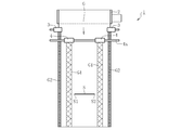
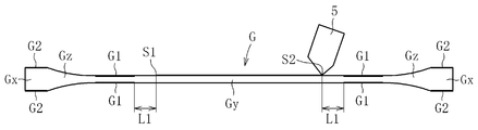
- FIG. 1 is a vertical cross-sectional side view showing a schematic configuration of a manufacturing apparatus used for carrying out a method for manufacturing a glass plate according to an embodiment of the present invention. It is a principal part expanded cross-sectional top view of a glass ribbon which shows the state which is performing the cutting process of the manufacturing method of the glass plate which concerns on embodiment of this invention. It is a front view which shows the schematic structure of the manufacturing apparatus after the manufacturing method of the glass plate which concerns on embodiment of this invention is implemented.
- the glass plate manufacturing method according to the present embodiment is roughly classified into a molding step A1 for molding a glass ribbon by an overflow downdraw method and a cutting step for cutting a glass plate from the molded glass ribbon. A2 and.
- A2 and.
- the forming step A1 an end cooling process of cooling the widthwise end of the glass ribbon and a conveying process of feeding the glass ribbon downward are performed.
- a scribing process for engraving a scribe line on the glass ribbon and a splitting process for breaking the glass ribbon along the scribe line are performed.
- the glass plate manufacturing apparatus 1 is arranged immediately below the molded body 2 to cool the widthwise end of the glass ribbon G, and below the cooling roller 3. And a transport roller 4 for feeding the glass ribbon G downward. Further, the manufacturing apparatus 1 includes a scribe chip 5 for engraving a scribe line S on a glass ribbon G fed downward at a position lower than the transport roller 4, and a glass along the engraved scribe line S. And a folding device 6 for breaking the ribbon G.
- the cooling roller 3 is a cantilevered roller that is arranged in the internal space of the molding furnace together with the molded body 2.
- a pair of left and right cooling rollers 3 is provided, and in the side view shown in FIG. 3, the cooling rollers 3 sandwich the glass ribbon G from both front and rear sides.
- the transport rollers 4 are arranged in, for example, a plurality of upper and lower stages (one stage in the illustrated example) in the internal space (including the cooling zone) of the annealing furnace.
- the transport rollers 4 are mounted on both left and right sides of the roller shaft 4x, and in the side view shown in FIG. 3, the transport rollers 4 sandwich the glass ribbon G from both front and rear sides.
- the scribe line S is engraved on the glass ribbon G below the lowermost conveying roller 4. Further, the glass ribbon G does not have to be sandwiched by the transport rollers 4 of all the stages, and may be sandwiched by the transport rollers 4 of at least one stage.
- the transport roller 4 is located closer to the center in the width direction than the cooling roller 3.
- the contact portion G1 of the glass ribbon G with the transport roller 4 (hereinafter, referred to as the first contact portion G1) and the contact portion G2 with the cooling roller 3 (hereinafter, referred to as the second contact portion G2). It is located on the center side in the width direction.
- the first contact portion G1 is shown as a streak region with a relatively large pitch cross hatching
- the second contact portion G2 is with a relatively small pitch cross hatching region. It is illustrated as a circular area. In this case, unlike the illustrated example, even if the transport roller 4 and the cooling roller 3 overlap in the width direction, if the first contact portion G1 and the second contact portion G2 do not overlap in the width direction. Good.
- the scribe line S is engraved in the cutting step A2 for the glass ribbon G formed in the forming step A1. Specifically, since the glass ribbon G is fed downward, the scribe chip 5 is moved diagonally downward with respect to the width direction on the front side of the glass ribbon G. As a result, as shown in the drawing, a linear scribe line S is engraved on the glass ribbon G along the width direction (horizontal direction). In addition, on the rear surface side of the glass ribbon G, a member corresponding to a surface plate that receives a pressing force of the scribe chip 5, or a support roller or the like (not shown) that moves in synchronization with the scribe chip 5 is arranged.
- Both the start point S1 and the end point S2 of the scribe line S engraved on the glass ribbon G are located on the center side in the width direction of the first contact portion G1. Therefore, the scribe line S does not interfere with the first contact portion G1 and the second contact portion G2.
- the second contact portion G2 can be visually recognized because the surface is not smooth and has irregularities, but the first contact portion G1 may or may not be visible.
- FIG. 4 is a cross-sectional plan view (a diagram without hatching) showing a main part of the glass ribbon G in which the scribe line S is engraved by the scribe chip 5.
- a scribing tool is used as the scribing tip 5, but a scribing wheel or the like may be used instead.
- the widthwise end portion Gx of the glass ribbon G is thicker than the widthwise center side portion Gy.
- the widthwise central portion Gy of the glass ribbon G has the same plate thickness as the widthwise center, and the plate thickness is uniform over the entire length.
- a plate thickness changing portion Gz is formed in which the plate thickness gradually becomes smaller as it moves to the widthwise center side.
- the first contact portion G1 is located at the widthwise center side portion Gy of the glass ribbon G.
- the second contact portion G2 is a portion of the widthwise end portion Gx of the glass ribbon G with which the cooling roller 3 comes into contact.
- the starting point S1 and the ending point S2 of the scribe line S are located in the widthwise center side portion Gy of the glass ribbon G.
- the first contact portion G1 is a portion on the center side in the width direction than that of the glass ribbon G (hereinafter referred to as “fluff” or adhesion of glass powder, etc., on the surface of the transport roller 4 due to use over time.
- the central part has a lower strength.
- the strength of the first contact portion G1 is about 1/5 to 1/20 of the strength of the central portion.
- the widthwise distance L1 from the start point S1 and the end point S2 of the scribe line S to the first contact portion G1 is 10 to 100 mm. If the dimension L1 is less than 10 mm, the start point S1 and the end point S2 of the scribe line S are too close to the first contact portion G1 and the glass ribbon G starts from the first contact portion G when the scribe line S is engraved. There is a risk of vertical cracking. On the other hand, when the dimension L1 exceeds 100 mm, the dimension in the width direction of the glass ribbon G where the scribe line S is not formed becomes too long, and a large amount of glass powder scatters when performing folding. Therefore, if the dimension L1 is within the above numerical range, these problems can be avoided.
- the glass ribbon GP is cut as shown in FIG. 5 by breaking the glass ribbon G along the scribe line S by the breaking device 6.
- the folding device 6 may be configured to perform folding by bending the glass ribbon G, or it may be performed by pushing the engraved portion of the scribe line S from the rear surface side with a pushing tool (for example, a blade). May be configured to perform.
- the first contact portion G1 and the second contact portion G2 of the glass ribbon G do not overlap in the width direction. Therefore, the surface of the transport roller 4 is not affected by the unevenness of the second contact portion G2. As a result, problems such as glass powder entering the surface of the transport roller 4 do not occur, and the strength of the first contact portion G1 is prevented from decreasing. As a result, it is possible to prevent the glass ribbon G from being vertically cracked from the first contact portion G1 when the transport roller 4 feeds the glass ribbon G in the forming step A1. In this case, the strength of the first contact portion G1 is lower than that of the portion on the center side in the width direction as described above.
- the scribe line S is engraved at a portion closer to the center in the width direction than the first contact portion G1. Therefore, not only the second contact portion G2 but also the first contact portion G1 is less likely to be affected by engraving the scribe line S. As a result, even when the scribe line S is engraved in the cutting step A2, it is possible to prevent a situation in which vertical cracks occur in the glass ribbon G starting from the first contact portion G1.
- the glass ribbon G is formed by using the overflow downdraw method in the forming step A1 in the above embodiment, the glass ribbon G is formed by using another downdraw method such as the slot downdraw method. You may do it.
- the cutting step A2 for cutting the glass plate from the molded glass ribbon G is provided, but the cutting step A2 may be omitted.
- the glass ribbon G may be wound into a glass roll after removing the first contact portion G1 and the second contact portion G2 on both sides by cutting.
Landscapes
- Chemical & Material Sciences (AREA)
- Engineering & Computer Science (AREA)
- Materials Engineering (AREA)
- Organic Chemistry (AREA)
- Re-Forming, After-Treatment, Cutting And Transporting Of Glass Products (AREA)
- Processing Of Stones Or Stones Resemblance Materials (AREA)
Abstract
成形体2の直下方でガラスリボンGの幅方向端部を冷却する冷却ローラ3と、冷却ローラ3よりも下方に配置されてガラスリボンGを下方に送る搬送ローラ4とを有するガラス板GPの製造方法において、ガラスリボンGの搬送ローラ4との接触部G1を冷却ローラ3との接触部G2よりも幅方向中央側に位置させる。
Description
本発明は、ガラス板の製造方法に係り、詳しくは、ダウンドロー法でガラスリボンを成形する製造方法に関する。
周知のように、ダウンドロー法(例えばオーバーフローダウンドロー法)を用いたガラス板の製造方法は、ガラスリボンを成形する成形工程と、成形されたガラスリボンからガラス板を切り出す切り出し工程とを備えている。
具体例として、特許文献1には、成形体の直下方でガラスリボンの幅方向端部を冷却する冷却ローラ(板引きローラ)と、冷却ローラよりも下方に配置されてガラスリボンを下方に送る複数の搬送ローラ(アニールローラ及び支持ローラ)とを用いて成形工程を行うことが開示されている。また、特許文献1には、複数の搬送ローラの下方位置でガラスリボンにスクライブ線を刻設し、このガラスリボンをスクライブ線に沿って折り割ることで、短尺のガラス板を切り出す切り出し工程も開示されている。
一方、特許文献1(同文献の図4等)には、切り出し工程を行う際に、ガラスリボンの幅方向端部(幅方向中央部よりも厚肉の耳部)にスクライブチップでスクライブ線を刻設することが開示されている。詳しくは、同文献には、スクライブ線の終点を、ガラスリボンの一方側の幅方向端部に位置させることが開示されている。そして、ガラスリボンの幅方向端部は、冷却ローラとの接触部に相当する(同文献の図1参照)。
さらに、特許文献1(同文献の図1)には、成形工程を行う際に、ガラスリボンの冷却ローラとの接触部と搬送ローラとの接触部とが幅方向でオーバーラップしている状態が開示されている。
ダウンドロー法で成形されるガラスリボンの冷却ローラとの接触部は、該ガラスリボンの幅方向中央側の部位と比較して表面が平滑ではない。そのため、特許文献1に開示のように、冷却ローラとの接触部と搬送ローラとの接触部とがガラスリボンの幅方向でオーバーラップしていると、搬送ローラの表面が、冷却ローラとの接触部における平滑でない表面に接触する。この状態の下では、経時使用に伴って搬送ローラの表面に摩耗による凹凸が形成されるおそれがある。この搬送ローラの表面の凹部にガラス粉が入り込むと、搬送ローラとの接触部に傷が入る等により該接触部の強度低下を招くおそれがある。そのため、ガラスリボンが下方に送られている間に、この接触部を起点としてガラスリボンに縦割れが発生し易くなる。
以上の観点から、本発明は、成形されたガラスリボンに縦割れが発生する事態を抑止することを課題とする。
上記課題を解決するために創案された本発明は、ダウンドロー法によってガラスリボンを成形する成形工程を備え、前記成形工程では、冷却ローラがガラスリボンの幅方向端部を冷却する処理と、前記冷却ローラよりも下方に配置された搬送ローラがガラスリボンを下方に送る処理とが行われるガラス板の製造方法であって、ガラスリボンの前記搬送ローラとの接触部を前記冷却ローラとの接触部よりも幅方向中央側に位置させることに特徴づけられる。ここで、上記の「接触部」は、冷却ローラ及び搬送ローラがそれぞれガラスリボンに接触している部位に限られず、接触した跡となる部位をも含む(以下、同様)。
このような構成によれば、ガラスリボンの搬送ローラとの接触部と冷却ローラとの接触部とが幅方向でオーバーラップしていない。そのため、成形工程で搬送ローラがガラスリボンを送る際に搬送ローラとの接触部を起点としてガラスリボンに縦割れが発生する事態を抑止することができる。
この方法において、成形されたガラスリボンからガラス板を切り出す切り出し工程をさらに備え、前記切り出し工程では、下方に送られているガラスリボンに前記搬送ローラよりも下方位置でスクライブ線を刻設する処理と、前記スクライブ線に沿ってガラスリボンを折り割る処理とが行われ、前記スクライブ線の始点及び終点を、ガラスリボンの前記搬送ローラとの接触部よりも幅方向中央側に位置させることが好ましい。
このようにすれば、スクライブ線は、搬送ローラとの接触部よりも幅方向中央側の部位に刻設される。そのため、切り出し工程でスクライブ線を刻設する際に強度が低い冷却ローラとの接触部や搬送ローラとの接触部を起点としてガラスリボンに縦割れが発生する事態をも抑止することができる。
本発明によれば、成形されたガラスリボンに縦割れが発生する事態を抑止することができる。
以下、本発明の実施形態に係るガラス板の製造方法について添付図面を参照しつつ説明する。
図1に示すように、本実施形態に係るガラス板の製造方法は、大別すると、オーバーフローダウンドロー法によってガラスリボンを成形する成形工程A1と、成形されたガラスリボンからガラス板を切り出す切り出し工程A2とを備える。成形工程A1では、ガラスリボンの幅方向端部を冷却する端部冷却処理と、ガラスリボンを下方に送る搬送処理とが行われる。また、切り出し工程A2では、ガラスリボンにスクライブ線を刻設するスクライブ処理と、ガラスリボンをスクライブ線に沿って折り割る折割処理とが行われる。
図2及び図3は、成形工程A1及び切り出し工程A2を実行するために用いられるガラス板の製造装置1を例示している。これら各図に示すように、ガラス板の製造装置1は、成形体2の直下方に配置されてガラスリボンGの幅方向端部を冷却する冷却ローラ3と、冷却ローラ3の下方に配置されてガラスリボンGを下方に送る搬送ローラ4とを有する。また、この製造装置1は、下方に送られているガラスリボンGに搬送ローラ4よりも下方位置でスクライブ線Sを刻設するスクライブチップ5と、この刻設されたスクライブ線Sに沿ってガラスリボンGを折り割る折割装置6とを有する。
冷却ローラ3は、成形体2と共に成形炉の内部空間に配設される片持ちのローラである。図2に示す正面視では、冷却ローラ3が左右に一対備えられ、図3に示す側面視では、それら冷却ローラ3がガラスリボンGを前後両側から挟持している。搬送ローラ4は、アニール炉の内部空間(冷却ゾーンを含む)に例えば上下複数段(図例では一段)に配設される。図2に示す正面視では、搬送ローラ4がローラ軸4xの左右両側に装着され、図3に示す側面視では、それら搬送ローラ4がガラスリボンGを前後両側から挟持している。なお、搬送ローラ4が上下複数段に配設される場合には、最下段の搬送ローラ4の下方位置でガラスリボンGにスクライブ線Sが刻設される。また、ガラスリボンGは、全ての段の搬送ローラ4によって挟持されていなくてもよく、少なくとも一段の搬送ローラ4によって挟持されていればよい。
以下、本実施形態に係るガラス板の製造方法を詳細に説明する。
図2に示すように、成形工程A1では、搬送ローラ4を冷却ローラ3よりも幅方向中央側に位置させている。加えて、成形工程A1では、ガラスリボンGの搬送ローラ4との接触部G1(以下、第一接触部G1という)を、冷却ローラ3との接触部G2(以下、第二接触部G2という)よりも幅方向中央側に位置させている。図2には、第一接触部G1を、相対的にピッチの大きいクロスハッチングを付した筋状の領域として図示し、第二接触部G2を、相対的にピッチの小さいクロスハッチングを付した筋状の領域として図示している。この場合、図例とは異なり、搬送ローラ4と冷却ローラ3とが幅方向でオーバーラップしていても、第一接触部G1と第二接触部G2とが幅方向でオーバーラップしていなければよい。
成形工程A1で成形されたガラスリボンGに対しては、切り出し工程A2でスクライブ線Sを刻設する。具体的には、ガラスリボンGが下方に送られているため、スクライブチップ5を、ガラスリボンGの前面側で幅方向に対して斜め下方に移動させる。これにより、図示のように、ガラスリボンGに幅方向(水平方向)に沿う直線状のスクライブ線Sが刻設される。なお、ガラスリボンGの後面側には、スクライブチップ5の押圧力を受ける定盤に相当する部材、或いは、スクライブチップ5と同期して移動するサポートローラ等(図示略)が配置される。
ガラスリボンGに刻設されるスクライブ線Sの始点S1及び終点S2は、何れも、第一接触部G1の幅方向中央側に位置している。したがって、スクライブ線Sは、第一接触部G1及び第二接触部G2と干渉しない。なお、第二接触部G2は、表面が平滑でなく凹凸が形成されているために視認することができるが、第一接触部G1は、視認することができる場合とできない場合とがある。
図4は、スクライブチップ5によってスクライブ線Sが刻設されたガラスリボンGの要部を示す横断平面図(ハッチングを省略した図)である。なお、本実施形態では、スクライブチップ5として、けがき工具を使用しているが、これに代えて、スクライブホイール等を使用してもよい。同図に示すように、ガラスリボンGの幅方向端部Gxは、幅方向中央側寄り部Gyよりも板厚が厚くなっている。ガラスリボンGの幅方向中央側寄り部Gyは、幅方向中央と板厚が同一であって、全長に亘って板厚が均一とされている。ガラスリボンGの幅方向端部Gxと幅方向中央側寄り部Gyとの間には、幅方向中央側に移行するに連れて板厚が漸次薄くなる板厚変化部Gzが形成されている。
図例では、第一接触部G1が、ガラスリボンGの幅方向中央側寄り部Gyに位置している。第二接触部G2は、ガラスリボンGの幅方向端部Gxにおける冷却ローラ3が接触する部位である。また、図例では、スクライブ線Sの始点S1及び終点S2が、ガラスリボンGの幅方向中央側寄り部Gyに位置している。
ここで、第一接触部G1は、搬送ローラ4の表面に経時使用に伴う毛羽立ちやガラス粉の付着等が生じることに起因して、ガラスリボンGのそれよりも幅方向中央側の部位(以下、中央部という)と比較して強度が低くなる。例えば、第一接触部G1の強度は、中央部の強度の約1/5~1/20である。
図4に示すように、スクライブ線Sの始点S1及び終点S2から第一接触部G1までの幅方向離隔寸法L1は、10~100mmとすることが好ましい。この寸法L1が10mm未満であると、スクライブ線Sの始点S1及び終点S2が第一接触部G1に近づき過ぎて、スクライブ線Sを刻設する際に第一接触部Gを起点としてガラスリボンGに縦割れが発生するおそれがある。一方、この寸法L1が100mmを超えると、ガラスリボンGにスクライブ線Sが形成されない部位の幅方向寸法が長くなり過ぎて、折り割りを行う際に多量のガラス粉が飛散する。したがって、この寸法L1が上記の数値範囲内にあれば、これらの不具合が回避される。
切り出し工程A2では、スクライブ線Sを刻設した後、折割装置6によってガラスリボンGをスクライブ線Sに沿って折り割ることで、図5に示すようにガラス板GPを切り出す。折割装置6は、ガラスリボンGを折り曲げることによって折り割りを行う構成であってもよく、或いは、スクライブ線Sの刻設部位を後面側から突き工具(例えばブレード)で突き押すことによって折り割りを行う構成であってもよい。
上述の本実施形態に係るガラス板の製造方法によれば、次に示すような効果を奏する。ガラスリボンGの第一接触部G1と第二接触部G2は、幅方向でオーバーラップしていない。そのため、搬送ローラ4の表面は、第二接触部G2の凹凸の影響を受けない。これにより、搬送ローラ4の表面にガラス粉が入り込む等の不具合が生じなくなって、第一接触部G1の強度低下が抑制される。その結果、成形工程A1で搬送ローラ4がガラスリボンGを送る際に第一接触部G1を起点としてガラスリボンGに縦割れが発生する事態を抑止することができる。この場合、第一接触部G1は、既述のようにそれよりも幅方向中央側の部位と比較して強度が低い。しかし、スクライブ線Sは、第一接触部G1よりも幅方向中央側の部位に刻設される。そのため、第二接触部G2のみならず第一接触部G1も、スクライブ線Sを刻設することによる影響を受け難くなる。その結果、切り出し工程A2でスクライブ線Sを刻設する際に第一接触部G1を起点としてガラスリボンGに縦割れが発生する事態をも抑止することができる。
なお、以上の実施形態では、成形工程A1でオーバーフローダウンドロー法を用いてガラスリボンGを成形するようにしたが、スロットダウンドロー法等の他のダウンドロー法を用いてガラスリボンGを成形するようにしてもよい。
以上の実施形態では、成形されたガラスリボンGからガラス板を切り出す切り出し工程A2を設けたが、切り出し工程A2を省略してもよい。この場合、ガラスリボンGを、切断により両側の第一接触部G1及び第二接触部G2をそれぞれ除去した後で巻き取ってガラスロールとしてもよい。
1 ガラス板の製造装置
3 冷却ローラ
4 搬送ローラ
A1 成形工程
A2 切り出し工程
G ガラスリボン
G1 搬送ローラとの接触部(第一接触部)
G2 冷却ローラとの接触部(第二接触部)
GP ガラス板
Gx ガラスリボンの幅方向端部
S スクライブ線
S1 スクライブ線の始点
S2 スクライブ線の終点
3 冷却ローラ
4 搬送ローラ
A1 成形工程
A2 切り出し工程
G ガラスリボン
G1 搬送ローラとの接触部(第一接触部)
G2 冷却ローラとの接触部(第二接触部)
GP ガラス板
Gx ガラスリボンの幅方向端部
S スクライブ線
S1 スクライブ線の始点
S2 スクライブ線の終点
Claims (2)
- ダウンドロー法によってガラスリボンを成形する成形工程を備え、
前記成形工程では、冷却ローラがガラスリボンの幅方向端部を冷却する処理と、前記冷却ローラよりも下方に配置された搬送ローラがガラスリボンを下方に送る処理とが行われるガラス板の製造方法であって、
ガラスリボンの前記搬送ローラとの接触部を前記冷却ローラとの接触部よりも幅方向中央側に位置させることを特徴とするガラス板の製造方法。 - 成形されたガラスリボンからガラス板を切り出す切り出し工程をさらに備え、
前記切り出し工程では、下方に送られているガラスリボンに前記搬送ローラよりも下方位置でスクライブ線を刻設する処理と、前記スクライブ線に沿ってガラスリボンを折り割る処理とが行われ、
前記スクライブ線の始点及び終点を、ガラスリボンの前記搬送ローラとの接触部よりも幅方向中央側に位置させることを特徴とする請求項1に記載のガラス板の製造方法。
Priority Applications (2)
| Application Number | Priority Date | Filing Date | Title |
|---|---|---|---|
| KR1020217012370A KR102733862B1 (ko) | 2018-12-18 | 2019-11-26 | 유리판의 제조 방법 |
| CN201980078133.1A CN113165935B (zh) | 2018-12-18 | 2019-11-26 | 玻璃板的制造方法 |
Applications Claiming Priority (2)
| Application Number | Priority Date | Filing Date | Title |
|---|---|---|---|
| JP2018236661A JP7148869B2 (ja) | 2018-12-18 | 2018-12-18 | ガラス板の製造方法 |
| JP2018-236661 | 2018-12-18 |
Publications (1)
| Publication Number | Publication Date |
|---|---|
| WO2020129543A1 true WO2020129543A1 (ja) | 2020-06-25 |
Family
ID=71102114
Family Applications (1)
| Application Number | Title | Priority Date | Filing Date |
|---|---|---|---|
| PCT/JP2019/046073 Ceased WO2020129543A1 (ja) | 2018-12-18 | 2019-11-26 | ガラス板の製造方法 |
Country Status (4)
| Country | Link |
|---|---|
| JP (1) | JP7148869B2 (ja) |
| KR (1) | KR102733862B1 (ja) |
| CN (1) | CN113165935B (ja) |
| WO (1) | WO2020129543A1 (ja) |
Families Citing this family (1)
| Publication number | Priority date | Publication date | Assignee | Title |
|---|---|---|---|---|
| CN117534308A (zh) * | 2023-11-13 | 2024-02-09 | 湖南旗滨电子玻璃股份有限公司 | 玻璃掰断装置及玻璃生产设备 |
Citations (4)
| Publication number | Priority date | Publication date | Assignee | Title |
|---|---|---|---|---|
| JP2010215428A (ja) * | 2009-03-13 | 2010-09-30 | Avanstrate Inc | ガラス板の製造方法および製造装置 |
| JP2016088784A (ja) * | 2014-10-31 | 2016-05-23 | AvanStrate株式会社 | ガラス板の製造方法、及び、ガラス板の製造装置 |
| JP2016190754A (ja) * | 2015-03-31 | 2016-11-10 | AvanStrate株式会社 | ガラス板の製造方法、及び、ガラス板の製造装置 |
| JP2019116415A (ja) * | 2017-12-26 | 2019-07-18 | AvanStrate株式会社 | ガラス基板の製造方法、及びガラス基板製造装置 |
Family Cites Families (5)
| Publication number | Priority date | Publication date | Assignee | Title |
|---|---|---|---|---|
| US20070062219A1 (en) * | 2005-09-22 | 2007-03-22 | Blevins John D | Methods of fabricating flat glass with low levels of warp |
| JP5177790B2 (ja) * | 2006-10-24 | 2013-04-10 | 日本電気硝子株式会社 | ガラスリボンの製造装置及びその製造方法 |
| JP6628032B2 (ja) * | 2015-12-21 | 2020-01-08 | 日本電気硝子株式会社 | ガラス板の製造装置 |
| JP6798289B2 (ja) | 2016-12-02 | 2020-12-09 | 日本電気硝子株式会社 | 板ガラスの製造方法 |
| KR102179884B1 (ko) * | 2017-12-26 | 2020-11-18 | 아반스트레이트 가부시키가이샤 | 유리 기판의 제조 방법, 및 유리 기판 제조 장치 |
-
2018
- 2018-12-18 JP JP2018236661A patent/JP7148869B2/ja active Active
-
2019
- 2019-11-26 WO PCT/JP2019/046073 patent/WO2020129543A1/ja not_active Ceased
- 2019-11-26 CN CN201980078133.1A patent/CN113165935B/zh active Active
- 2019-11-26 KR KR1020217012370A patent/KR102733862B1/ko active Active
Patent Citations (4)
| Publication number | Priority date | Publication date | Assignee | Title |
|---|---|---|---|---|
| JP2010215428A (ja) * | 2009-03-13 | 2010-09-30 | Avanstrate Inc | ガラス板の製造方法および製造装置 |
| JP2016088784A (ja) * | 2014-10-31 | 2016-05-23 | AvanStrate株式会社 | ガラス板の製造方法、及び、ガラス板の製造装置 |
| JP2016190754A (ja) * | 2015-03-31 | 2016-11-10 | AvanStrate株式会社 | ガラス板の製造方法、及び、ガラス板の製造装置 |
| JP2019116415A (ja) * | 2017-12-26 | 2019-07-18 | AvanStrate株式会社 | ガラス基板の製造方法、及びガラス基板製造装置 |
Also Published As
| Publication number | Publication date |
|---|---|
| KR102733862B1 (ko) | 2024-11-26 |
| KR20210100595A (ko) | 2021-08-17 |
| JP2020097504A (ja) | 2020-06-25 |
| CN113165935A (zh) | 2021-07-23 |
| JP7148869B2 (ja) | 2022-10-06 |
| CN113165935B (zh) | 2023-03-14 |
Similar Documents
| Publication | Publication Date | Title |
|---|---|---|
| JP2012096936A (ja) | ガラスリボンの耳切断装置および耳切断方法とガラス製品の製造装置および製造方法 | |
| JP4947488B2 (ja) | ガラス板の製造方法及びその装置 | |
| CN203653429U (zh) | 薄板玻璃材料的分断装置 | |
| KR102246033B1 (ko) | 유리 필름의 제조 방법 | |
| JP2015223818A (ja) | 基板分断方法並びに基板分断装置 | |
| KR102267240B1 (ko) | 띠형상 유리 필름의 제조 방법 및 제조 장치 | |
| JP6798289B2 (ja) | 板ガラスの製造方法 | |
| JP7148869B2 (ja) | ガラス板の製造方法 | |
| WO2020129544A1 (ja) | ガラス板の製造方法 | |
| CN214528714U (zh) | 玻璃板的制造装置 | |
| KR102179884B1 (ko) | 유리 기판의 제조 방법, 및 유리 기판 제조 장치 | |
| KR101756072B1 (ko) | 롤러를 이용한 비금속 재료의 절단 장치 및 절단 방법 | |
| CN114650971A (zh) | 玻璃膜的制造方法 | |
| JP2014125419A (ja) | ガラス板製造装置、および、ガラス板製造方法 | |
| JP2023166755A (ja) | ガラス板の製造方法、ガラス板及びガラス板梱包体 | |
| JP2023166753A (ja) | ガラス板の製造方法、ガラス板及びガラス板梱包体 | |
| JP6714676B2 (ja) | ガラス基板の製造方法、及びガラス基板製造装置 | |
| CN115996895B (zh) | 玻璃物品的制造方法 | |
| JP5042690B2 (ja) | 鋳片の幅圧下設備 | |
| JP2026064419A (ja) | 成形体及びガラス物品の製造方法 | |
| WO2022202234A1 (ja) | ガラスフィルム製造方法及びその製造装置 | |
| CN114845963A (zh) | 玻璃带的切断装置、切断玻璃带的方法以及玻璃板的制造方法 | |
| TW201410621A (zh) | 薄板玻璃之製造方法 | |
| JP2008254048A (ja) | 鋳片の幅圧下設備の操業方法 |
Legal Events
| Date | Code | Title | Description |
|---|---|---|---|
| 121 | Ep: the epo has been informed by wipo that ep was designated in this application |
Ref document number: 19899754 Country of ref document: EP Kind code of ref document: A1 |
|
| NENP | Non-entry into the national phase |
Ref country code: DE |
|
| 122 | Ep: pct application non-entry in european phase |
Ref document number: 19899754 Country of ref document: EP Kind code of ref document: A1 |