WO2020129534A1 - Vehicle air-conditioning device - Google Patents
Vehicle air-conditioning device Download PDFInfo
- Publication number
- WO2020129534A1 WO2020129534A1 PCT/JP2019/045666 JP2019045666W WO2020129534A1 WO 2020129534 A1 WO2020129534 A1 WO 2020129534A1 JP 2019045666 W JP2019045666 W JP 2019045666W WO 2020129534 A1 WO2020129534 A1 WO 2020129534A1
- Authority
- WO
- WIPO (PCT)
- Prior art keywords
- air
- blower
- sensor
- case
- vehicle
- Prior art date
Links
Images


Classifications
-
- B—PERFORMING OPERATIONS; TRANSPORTING
- B60—VEHICLES IN GENERAL
- B60H—ARRANGEMENTS OF HEATING, COOLING, VENTILATING OR OTHER AIR-TREATING DEVICES SPECIALLY ADAPTED FOR PASSENGER OR GOODS SPACES OF VEHICLES
- B60H1/00—Heating, cooling or ventilating [HVAC] devices
-
- B—PERFORMING OPERATIONS; TRANSPORTING
- B60—VEHICLES IN GENERAL
- B60H—ARRANGEMENTS OF HEATING, COOLING, VENTILATING OR OTHER AIR-TREATING DEVICES SPECIALLY ADAPTED FOR PASSENGER OR GOODS SPACES OF VEHICLES
- B60H3/00—Other air-treating devices
- B60H3/06—Filtering
-
- F—MECHANICAL ENGINEERING; LIGHTING; HEATING; WEAPONS; BLASTING
- F24—HEATING; RANGES; VENTILATING
- F24F—AIR-CONDITIONING; AIR-HUMIDIFICATION; VENTILATION; USE OF AIR CURRENTS FOR SCREENING
- F24F11/00—Control or safety arrangements
- F24F11/62—Control or safety arrangements characterised by the type of control or by internal processing, e.g. using fuzzy logic, adaptive control or estimation of values
- F24F11/63—Electronic processing
-
- G—PHYSICS
- G01—MEASURING; TESTING
- G01N—INVESTIGATING OR ANALYSING MATERIALS BY DETERMINING THEIR CHEMICAL OR PHYSICAL PROPERTIES
- G01N15/00—Investigating characteristics of particles; Investigating permeability, pore-volume, or surface-area of porous materials
- G01N15/06—Investigating concentration of particle suspensions
-
- G—PHYSICS
- G01—MEASURING; TESTING
- G01N—INVESTIGATING OR ANALYSING MATERIALS BY DETERMINING THEIR CHEMICAL OR PHYSICAL PROPERTIES
- G01N21/00—Investigating or analysing materials by the use of optical means, i.e. using sub-millimetre waves, infrared, visible or ultraviolet light
- G01N21/17—Systems in which incident light is modified in accordance with the properties of the material investigated
- G01N21/47—Scattering, i.e. diffuse reflection
- G01N21/49—Scattering, i.e. diffuse reflection within a body or fluid
- G01N21/53—Scattering, i.e. diffuse reflection within a body or fluid within a flowing fluid, e.g. smoke
-
- Y—GENERAL TAGGING OF NEW TECHNOLOGICAL DEVELOPMENTS; GENERAL TAGGING OF CROSS-SECTIONAL TECHNOLOGIES SPANNING OVER SEVERAL SECTIONS OF THE IPC; TECHNICAL SUBJECTS COVERED BY FORMER USPC CROSS-REFERENCE ART COLLECTIONS [XRACs] AND DIGESTS
- Y02—TECHNOLOGIES OR APPLICATIONS FOR MITIGATION OR ADAPTATION AGAINST CLIMATE CHANGE
- Y02A—TECHNOLOGIES FOR ADAPTATION TO CLIMATE CHANGE
- Y02A50/00—TECHNOLOGIES FOR ADAPTATION TO CLIMATE CHANGE in human health protection, e.g. against extreme weather
- Y02A50/20—Air quality improvement or preservation, e.g. vehicle emission control or emission reduction by using catalytic converters
- Y02A50/2351—Atmospheric particulate matter [PM], e.g. carbon smoke microparticles, smog, aerosol particles, dust
Definitions
- the present disclosure relates to a vehicle air conditioner including a particle detection unit that detects a particle concentration of a particulate matter.
- Patent Document 1 there is a device described in Patent Document 1 as a device for detecting particles in the air.
- This device includes a housing that forms an air passage, and an air motor that sucks air inside the vehicle compartment or air outside the vehicle compartment into the housing. Then, the concentration of particles is detected by irradiating the air sucked into the housing with light and receiving the scattered light which is scattered by hitting the light.
- the device described in Patent Document 1 cannot accurately detect the concentration of particles contained in distant air because the air volume of the air motor that sucks air into the housing is small.
- the housing is arranged inside the instrument panel of the vehicle and the concentration of particles contained in the air near the body of the occupant seated on the seat is detected, it is possible to detect the concentration of particles in the air near the body of the occupant. Since air cannot be sufficiently sucked in, there is a problem that the concentration of particles cannot be detected accurately. Further, when the air volume of the air motor is small, it takes a long time for the air to reach the inside of the housing, which causes a problem that the responsiveness is not good.
- the suction capacity of the air motor is increased, it is possible to suck the air near the body of the vehicle occupant into the housing.However, if the suction capacity of the air motor is increased, turbulent flow will occur, which will increase the flow velocity, and The concentration cannot be detected accurately.
- the present disclosure aims to enable detection of the concentration of particulate matter contained in distant air with higher accuracy and responsiveness.
- an air conditioner for a vehicle is arranged inside an air conditioning case that forms an air passage through which air blown into a vehicle compartment flows, and sucks air into the inside of the air conditioning case.
- An air blower and a particle detection unit that detects the particle concentration of the particulate matter contained in the air are provided.
- the particle detection unit includes a light emitting unit that irradiates the air with light, and the light emitted by the light emitting unit hits the particulate matter.
- It has a light receiving part that receives scattered scattered light, and a sensor case that houses the light emitting part and the light receiving part.
- a part of the air sucked into the inside of the air conditioning case by the operation of the blower is inside the sensor case.
- a sensor introduction port for introducing into is formed.
- the sensor case is formed with the sensor introduction port for introducing a part of the air sucked into the air conditioning case by the operation of the blower into the sensor case.
- the concentration of the particulate matter contained can be detected more accurately and with high responsiveness.
- FIG. 3 is a diagram showing a light emitting unit and a light receiving unit of a particle detecting unit. It is the figure which showed the flow of the air at the time of the operation
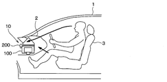
- the vehicle air conditioner 10 according to the first embodiment is an air conditioner mounted on the vehicle 1 and is a device for performing air conditioning in the vehicle interior.
- the vehicle air conditioner 10 includes an air conditioning unit 100 and a particle detector 200.
- the vehicle air conditioner 10 is arranged inside the instrument panel 2 of the vehicle 1.
- the particle detection unit 200 detects the particle concentration of air in the vicinity of the body of an occupant seated on the seat 3 of the vehicle 1.
- the value of the particle concentration detected by the particle detecting unit 200 is displayed on, for example, a display unit arranged in the meter.
- the air conditioning unit 100 performs air conditioning on the air taken in from the outside and supplies the conditioned air into the vehicle interior.
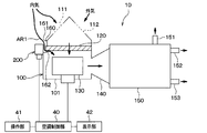
- the air conditioning unit 100 includes a blower storage section 101, a blower 130, a connecting section 140, and an air conditioning section 150.
- the blower storage part 101 is a part of the vehicle air conditioner 10 that takes in air from the outside.
- a blower 130 which will be described later, is housed inside the blower housing portion 101.
- An inner air inlet 111 and an outer air inlet 112 are formed in the blower storage portion 101.
- the inside air inlet 111 is an opening formed as an inlet for air introduced from the passenger compartment.
- the outside air inlet 112 is an opening formed as an inlet for air introduced from outside the vehicle.
- the space outside the vehicle and the outside air inlet 112 are connected by a duct (not shown).
- An inside/outside air switching door (not shown) is provided between the inside air inlet 111 and the outside air inlet 112 in the blower storage unit 101.
- the operation of the inside/outside air switching door adjusts the ratio of the air flowing in from the inside air inlet 111 to the air flowing in from the outside air inlet 112. Since a publicly known one can be adopted as the structure of such an inside/outside air switching door, a concrete illustration and description thereof will be omitted.
- a particle filter 120 is arranged at a position on the upstream side (upper side in FIG. 1) of the blower 130 along the air flow direction in the blower housing 101.
- the particle filter 120 is a filter for removing particles from the air flowing in from the inside air inlet 111 or the outside air inlet 112. As the air passes through the particle filter 120, clean air with a reduced particle concentration is blown into the vehicle interior.
- the blower 130 is a blower that blows out air so that it is blown into the vehicle interior.
- the blower 130 corresponds to a blower that sucks air into the air conditioning case.
- blower 130 When the blower 130 is driven, air is drawn into the blower housing 101 from the inside air inlet 111 and the outside air inlet 112. The air is blown into the vehicle compartment through the connection unit 140 and the air conditioning unit 150 described below.
- connection part 140 is a part provided as a flow path that connects the blower storage part 101 and the air conditioning part 150.
- the blower storage portion 101 and the connection portion 140 are integrally formed.
- the air conditioner 150 is a part that adjusts the temperature of the air. Inside the air conditioning unit 150, an evaporator for dehumidifying and cooling air, a heater core for heating air, an air mix door for adjusting the amount of air flowing through each of the evaporator and the heater core, and the like are arranged.
- the blower storage unit 101, the connection unit 140, and the air conditioning unit 150 correspond to an air conditioning case that forms an air passage through which air blown into the vehicle interior flows.
- a defroster blowing unit 151, a face blowing unit 152, and a foot blowing unit 153 are provided in the downstream portion of the air conditioning unit 150 along the air flow direction.
- the defroster blowout part 151 is a part which blows out conditioned air toward the window of the vehicle.
- the face blowing section 152 is a section that blows out the conditioned air toward the face of the vehicle occupant.
- the foot blowout part 153 is a part that blows out the conditioned air toward the feet of an occupant of the vehicle.
- a door (not shown) is provided in each of the defroster blowing unit 151, the face blowing unit 152, and the foot blowing unit 153, and the flow rate of the air blown out from each blowing unit is adjusted by the opening of the door. Since a known structure can be adopted as the structure of the air conditioning unit 150 as described above, a concrete illustration and description thereof will be omitted.
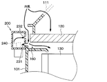
- an air introducing chamber 160 is formed at a position in the blower housing 101 near the end of the particle filter 120.
- the air introducing chamber 160 is formed as a space in which air introduced from the outside of the air conditioning unit 100 into the inside of the air conditioning unit 100 (specifically, inside the blower housing 101) flows. The air flowing through the air introduction chamber 160 bypasses the particle filter 120 and flows.
- An opening 161 serving as an air inlet of the air introduction chamber 160 is formed at a position above the particle filter 120 and a particle detection unit 200 described later.
- the opening 161 communicates the space around the air conditioning unit 100 with the air introduction chamber 160.
- the opening 162, which serves as an air outlet, in the air introduction chamber 160 is formed at a position slightly below the particle filter 120.
- the opening 162 connects the air introducing chamber 160 and a space in the blower housing portion 101 below the particle filter 120.
- the opening 162 corresponds to the air intake for the detection unit.
- the positions of the openings 161 and 162 as described above are merely examples.
- the openings 161 and 162 may be formed at positions different from the above.
- the air conditioning control unit 40 will be described.
- the air conditioning control unit 40 illustrated in FIG. 1 is a control device that controls the air conditioning unit 100.
- the air conditioning control unit 40 is an electronic control device including a storage unit configured by a non-transitional physical storage medium such as a semiconductor memory and a processor.
- the air conditioning control unit 40 executes the computer program stored in the storage unit. By executing this computer program, the method corresponding to the computer program is executed.
- the air conditioning control unit 40 controls the operation of each actuator by outputting a control signal to each actuator included in the air conditioning unit 150.
- the air conditioning control unit 40 performs various air conditioning controls on the air conditioning unit 150.
- the blower 130, the inside/outside air switching door, the air mix door, the face outlet opening door, the foot outlet opening door, and the defroster outlet opening door are drive-controlled by the air conditioning controller 40. It
- the air conditioning control unit 40 is connected with, for example, sensors such as the particle detection unit 200 and actuators such as doors, as well as an operation unit 41 and a display unit 42.
- the operation unit 41 is an operation unit operated by an occupant when adjusting the air volume, temperature, etc. of the conditioned air blown out from the air conditioning unit 150.
- the operation unit 41 is arranged, for example, on an instrument panel of a vehicle.
- the air volume of the conditioned air, the target room temperature in the passenger compartment, the outlet of the conditioned air, etc. can be set.
- the operation unit 41 outputs information indicating these settings, that is, operation information indicating an occupant operation performed on the operation device 44, to the air conditioning control unit 40.
- the air conditioning control unit 40 calculates the concentration of particles in the air in the vehicle compartment based on the output signal of the particle detection unit 200, and the calculated concentration of particles is displayed on, for example, the display unit 42 arranged in the meter. It also performs the process of displaying.
- the blower storage section 101 is arranged inside the instrument panel of the vehicle.
- the space inside the instrument panel that is, the space outside the air introduction chamber 160, is connected to the vehicle interior. Therefore, the air flowing into the air introduction chamber 160 from the opening 161 is the air in the vehicle compartment.
- the portion of the air conditioning unit 100 where the air introduction chamber 160 is formed is the portion to which the particle detection unit 200 is attached.
- the particle detector 200 is attached to the blower housing 101 from the outside so as to form a side portion of the air introduction chamber 160.
- the position of the upper end of the particle detector 200 is lower than the opening 161.
- the particle detection unit 200 is a sensor unit for measuring the concentration of particles in the air. As shown in FIG. 4, the particle detection unit 200 has a light emitting unit 210 having a light emitting element 211 and a light receiving unit 220 having a light receiving element 221.
- a part of the light emitted from the light emitting section 210 is scattered by particles in the air introduced into the particle detecting section 200, and a part of the light is detected by the light receiving section 220.
- the particle detecting unit 200 is configured to detect the presence or absence and the concentration of particles in the air based on the amount of light detected by the light receiving unit 220.
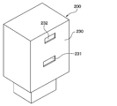
- the particle detection unit 200 has a sensor case 230 as shown in FIG.
- the sensor case 230 is a container that houses the light emitting unit 210, the light receiving unit 220, the sensor blower 240, and the like therein, and is formed in a substantially rectangular parallelepiped shape.
- a first opening 231 and a second opening 232 are formed on the surface of the sensor case 230 that forms the air introduction chamber 160.
- the first opening 231 is an opening formed so that the air from the air introducing chamber 160 flows in.
- the second opening 232 is an opening formed to discharge the air to the air introduction chamber 160, as described above.
- the second opening 232 in the present embodiment is formed at a position above the first opening 231.
- the particle detection unit 200 has a sensor blower 240 that adjusts the flow rate of the air introduced into the sensor case 230.
- the light emitting unit 210, the light receiving unit 220, and the sensor blower 240 are arranged inside the sensor case 230.
- the sensor blower 240 operates according to an instruction from the air conditioning control unit 40 described later.
- the sensor blower 240 sucks the air flowing through the air introduction chamber 160 into the sensor case 230 through the first opening 231.
- the maximum suction capacity of the sensor blower 240 is smaller than the maximum suction capacity of the blower 130.
- the particle detection unit 200 measures the concentration of particles in the air that has flowed into the sensor case 230 through the first opening 231.
- the air is the air in the vehicle compartment as described above.
- the air sucked into the sensor case 230 is discharged into the air introduction chamber 160 through the second opening 232.
- the suction capacity of the sensor blower 240 is increased, the air around the body of the vehicle occupant can be quickly sucked into the sensor case 230.
- the suction capacity of the sensor blower 240 is increased, turbulent flow is generated with an increase in flow velocity, and the particle concentration cannot be detected accurately.
- the vehicle air conditioner 10 of the present embodiment has a sensor introduction port for introducing a part of the air sucked into the blower housing portion 101 into the sensor case 230 by the operation of the blower 130 having a large suction capacity. There is.
- This sensor inlet corresponds to the first opening 231.
- the inside air in the vehicle compartment is introduced from the inside air inlet 111 to the blower storage unit 101 by the operation of the inside/outside air switching door.
- the inside air is sucked into the blower 130 from the inside air inlet 111 through the particle filter 120 and the blower housing portion 101, as shown in FIG.
- part of the air sucked into the blower storage unit 101 flows into the air introduction chamber 160. Then, a part of the air flowing into the air introducing chamber 160 is introduced into the sensor case 230 through the first opening 231.
- the particle detection unit 200 measures the concentration of particles in the air that has flowed into the sensor case 230 through the first opening 231.
- the air sucked into the sensor case 230 is discharged from the second opening 232 into the air introduction chamber 160 and sucked into the blower 130.
- air is further introduced from the air introduction chamber 160 into the sensor case 230 by the operation of the sensor blower 240. That is, in the vehicle air conditioner 10 of the present embodiment, air is introduced into the sensor case 230 from the air introduction chamber 160 not only by the operation of the blower 130 but also by the operation of the sensor blower 240. Therefore, it is possible to detect the particle concentration with high accuracy and responsiveness without generating turbulence.
- the air conditioning control unit 40 of the present embodiment controls the blower 130 so that the flow rate of the air sucked into the blower storage unit 101 increases as the traveling speed of the vehicle increases.
- the air near the body of the occupant is easily introduced into the sensor case 230, so that the concentration of particles in the air near the body of the occupant can be accurately detected.
- the air conditioning control unit 40 of the present embodiment increases the flow rate of air introduced into the sensor case 230 in a vehicle with a small suction capacity of the blower 130, compared with a vehicle with a large suction capacity of the blower 130.
- the sensor blower 240 is controlled so that
- the air conditioning control unit 40 of the present embodiment determines that the position of the seat 3 of the vehicle 1 is ahead of the predetermined position of the vehicle based on the signal indicating the position of the seat 3, the air conditioning control unit 40 of the blower storage unit 101 is further operated.
- the blower 130 is controlled to increase the flow rate of the air sucked into the inside.
- the air conditioning control unit 40 of the present embodiment controls the sensor blower 240 so that the flow rate of the air introduced into the sensor case 230 becomes an appropriate amount according to the mode.
- the air conditioning control unit 40 of the present embodiment determines that the flow rate of the air introduced into the sensor case 230 is an appropriate amount according to the signal indicating whether the door closing the face blowing unit 152 closes the face blowing unit 152.
- the sensor blower 240 is controlled so that
- the air flow path of the air conditioning case is divided into left and right, and the right and left independent temperature control type vehicle air conditioners that independently control the temperature of the air blown from the right air flow path and the left air flow path
- the air flow rates of the air blown from the air flow path and the left air flow path are different. Therefore, the air conditioning controller 40 of the present embodiment uses the sensor blower so that the flow rate of the air introduced into the sensor case 230 becomes an appropriate amount according to the air volume of the blown air blown out from the right air passage and the left air passage. Control 240.
- the air conditioning control unit 40 of the present embodiment compares the case where the seat air conditioning system is not operating with the case where the seat air conditioning system is operating.
- the sensor blower 240 is controlled so that the flow rate of air introduced into the sensor case 230 is increased.
- the air conditioning control unit 40 of the present embodiment compares the case where the rear air conditioner is not operating with the case where the seat air conditioner is operating.
- the sensor blower 240 is controlled so that the flow rate of air introduced into the sensor case 230 is increased.
- the vehicle air conditioner includes the air conditioning cases 101, 140, and 150 that form the air passages through which the air blown into the vehicle interior flows.
- the vehicle air conditioner includes a blower 130 that is arranged inside the air conditioning cases 101, 140, 150 and sucks air into the air conditioning cases 101, 140, 150.
- a particle detector 200 for detecting the particle concentration of the particulate matter contained in the air.
- the particle detecting unit 200 includes a light emitting unit 210 that irradiates air with light, a light receiving unit 220 that receives scattered light that is scattered by the light emitted by the light emitting unit 210 hitting a particulate matter, and the light emitting unit 210 and the light receiving unit 220. It has a sensor case 230 for housing the.
- the sensor case 230 is formed with a first opening 231 as a sensor introduction port for introducing a part of the air sucked into the air conditioning cases 101, 140 and 150 into the sensor case 230 by the operation of the blower 130. ing.
- the sensor case 230 has a first sensor introduction port as a sensor introduction port for introducing a part of the air sucked into the air conditioning cases 101, 140 and 150 by the operation of the blower 130 into the sensor case 230.
- One opening 231 is formed. Therefore, the concentration of the particulate matter contained in the distant air can be detected more accurately and with good responsiveness.
- the particle detection unit 200 has a sensor blower 240 that sucks a part of the air sucked into the air conditioning cases 101, 140, and 150 into the sensor case 230 through the first opening 231 serving as a sensor inlet. There is.
- the sensor blower 240 is arranged inside the sensor case 230. In this way, the sensor blower 240 disposed inside the sensor case 230 can introduce a part of the air sucked into the air conditioning cases 101, 140, and 150 into the sensor case 230.
- a portion of the air conditioning case 101, 140, 150 to which the sensor case 230 is attached is a space in which air introduced from the outside of the air conditioning case 101, 140, 150 into the air conditioning case 101, 140, 150 flows.
- An air introducing chamber 160 is formed. Then, the sensor blower 240 sucks a part of the air flowing through the air introducing chamber 160 into the sensor case 230.
- the sensor blower 240 can be provided so as to suck a part of the air flowing through the air introduction chamber 160 into the sensor case 230.
- the air introduction chamber 160 is formed in the blower storage portion 101 at a position near the end of the particle filter 120, and a part of the air flowing in the air introduction chamber 160 is formed. It is adapted to be introduced into the sensor case 230 of the particle detector 200.
- the air introduction chamber 160 is not formed in the blower storage part 101, and the particle detection part 200 is configured such that a part of the air introduced into the inside air inlet 111 is a particle. It is adapted to be introduced into the sensor case 230 of the detection unit 200.
- the particle detection unit 200 has a sensor blower 240 that adjusts the flow rate of air introduced into the sensor case 230.
- the sensor blower 240 is arranged inside the sensor case 230.
- the light emitting unit 210 and the light receiving unit 220 are also arranged inside the sensor case 230.
- the sensor blower 240 operates according to an instruction from the air conditioning control unit 40 described later.
- the sensor blower 240 sucks a part of the inside air introduced into the inside air inlet 111 into the sensor case 230 through the first opening 231.
- the maximum suction capacity of the sensor blower 240 is smaller than the maximum suction capacity of the blower 130.
- the particle detection unit 200 measures the concentration of particles in the air that has flowed into the sensor case 230 through the first opening 231.
- the air is the air in the vehicle compartment as described above.
- the air sucked into the sensor case 230 is discharged to the outside of the sensor case 230 through the second opening 232.
- the air conditioning control unit 40 of the present embodiment performs a process of adjusting the air volume of the sensor blower 240 according to the air volume of the blower 130. A flowchart of this process is shown in FIG. The air conditioning control unit 40 periodically executes the processing shown in FIG.
- the air conditioning controller 40 determines in S100 whether or not the blown air volume of the blower 130 is equal to or greater than a threshold value. Specifically, the blown air volume of the blower 130 is estimated based on the voltage supplied to the blower 130, and it is determined whether this blown air volume is equal to or more than a threshold value.
- the air conditioning control unit 40 reduces the air volume of the sensor blower 240 in S102. As a result, it is possible to prevent excessive air from being introduced into the sensor case 230.
- the air conditioning control unit 40 increases the air volume of the sensor blower 240 in S104. This makes it possible to introduce an appropriate amount of air into the sensor case 230.
- the air volume determination unit corresponding to step S100 determines whether or not the air volume of the blower is greater than or equal to a threshold value.
- the air volume adjusting unit corresponding to steps S102 and S104 reduces the intake air volume of the sensor blower when the air volume determining unit determines that the air volume of the blower is greater than or equal to the threshold value.
- the air volume adjustment unit increases the intake air volume of the sensor blower.
- the intake air volume of the sensor blower is reduced, and if the air flow rate of the blower is determined to be less than the threshold value by the air flow rate determination unit, It is possible to increase the intake air volume of the sensor blower.
- the vehicle air conditioner 10 according to the present embodiment is configured such that the air intake device for the detection unit takes in air from the outside of the blower storage unit 101 to the inside of the blower storage unit 101 at a position near the end of the particle filter 120 in the blower storage unit 101.
- An inlet 170 is formed. A part of the air flowing through the air intake 170 for the detection unit is introduced into the sensor case 230 of the particle detection unit 200.
- the vehicle air conditioner 10 of the present embodiment includes an opening/closing door 250 that adjusts the opening degree of the detection unit air intake 170.
- the opening/closing door 250 corresponds to a door member.
- the air conditioning control unit 40 adjusts the flow rate of air introduced into the sensor case 230 by the sensor blower 240 and adjusts the flow rate of air introduced from the outside of the blower storage unit 101 into the inside of the blower storage unit 101 by the opening/closing door 25. It is possible to do.
- the door member 250 opens the air intake 170 for the detection unit, the air that does not pass through the particle filter 120 is introduced into the air conditioning unit 150 through the air intake 170 for the detection unit.
- the door member 250 by closing the first opening 231 with the door member 250, it is possible to prevent the air that does not pass through the particle filter 120 from entering the air conditioning unit 150 through the detection unit air intake 170.
- an air inlet for a detection unit that takes in air from outside the air conditioning case 101, 140, 150 into the air conditioning case 101, 140, 150. 170 is formed.
- the vehicle air conditioner 10 includes a door member 250 that adjusts the opening degree of the detection unit air intake 170.
- the sensor blower 240 is arranged inside the sensor case 230, but the sensor blower 240 may be arranged outside the sensor case 230.
- the sensor blower 240 may be arranged in the air introducing chamber 160 so that air is sucked into the air introducing chamber 160 from the outside of the air conditioning case.
- the vehicle air conditioner of the third embodiment includes the opening/closing door 250 that adjusts the opening degree of the detection unit air intake 170.
- the vehicle air conditioner of the first embodiment described above is also included.
- An opening/closing door for adjusting the opening of the opening 162 may be provided.
- the present disclosure is not limited to the above-described embodiment, and can be modified as appropriate. Further, the above embodiments are not unrelated to each other, and can be appropriately combined unless a combination is obviously impossible. Further, in each of the above-mentioned embodiments, it goes without saying that the elements constituting the embodiment are not necessarily essential unless explicitly stated as being essential and in principle considered to be essential. Yes. Further, in each of the above-described embodiments, when numerical values such as the number of components of the embodiment, numerical values, amounts, ranges, etc. are referred to, it is clearly limited to a particular number and in principle limited to a specific number. The number is not limited to the specific number, except in the case of being performed.
- the vehicle air conditioner includes an air conditioning case that forms an air passage through which air blown into the vehicle interior flows, and an interior of the air conditioning case. And a blower that draws air into the inside of the air conditioning case. Further, a particle detection unit for detecting the particle concentration of the particulate matter contained in the air is provided.
- the particle detection unit includes a light emitting unit that irradiates air with light, a light receiving unit that receives scattered light when the light emitted by the light emitting unit hits the particulate matter and is scattered, and a sensor case that houses the light emitting unit and the light receiving unit.
- the sensor case is formed with a sensor introduction port for introducing a part of the air sucked into the air conditioning case into the sensor case by the operation of the blower.
- the particle detection unit has a sensor blower that sucks a part of the air sucked into the air conditioning case into the sensor case through the sensor inlet.
- the sensor blower is also arranged inside the sensor case.
- the sensor blower arranged inside the sensor case can introduce a part of the air sucked into the air conditioning case into the sensor case.
- an air introduction chamber that is a space in which air introduced from the outside of the air conditioning case into the inside of the air conditioning case flows is formed in a portion of the air conditioning case to which the sensor case is attached. .. Then, the sensor blower sucks a part of the air flowing through the air introduction chamber into the sensor case.
- a sensor blower can be installed so that part of the air flowing through the air introduction chamber is sucked into the sensor case.
- the vehicle air conditioner includes an air volume determination unit that determines whether or not the air volume of the blower is equal to or greater than a threshold value. Further, if the air flow rate of the blower is determined to be equal to or higher than the threshold value by the air flow rate determination unit, the intake air volume of the sensor blower is reduced, and if the air flow rate of the blower is determined to be less than the threshold value by the air flow rate determination unit, the sensor blower It is equipped with an air volume adjustment unit that increases the intake air volume.
- the intake air volume of the sensor blower is reduced, and if the air flow rate of the blower is determined to be less than the threshold value by the air flow rate determination unit, It is possible to increase the intake air volume of the sensor blower.
- an air inlet for the detection unit that takes in air from the outside of the air conditioning case to the inside of the air conditioning case is formed.
- the vehicle air conditioner includes a door member that adjusts the opening degree of the detection unit air intake.
- the first opening 231 corresponds to the sensor inlet
- the detection unit air intake 170 and the opening 162 correspond to the detection unit air intake
- the process of S100 corresponds to the air volume determination unit
- the processing corresponds to the air volume adjusting unit.
Abstract
This vehicle air-conditioning device comprises: an air-conditioning case (101, 140, 150) that forms an air passage through which air blown into the passenger compartment flows; a blower (130) that is disposed inside the air-conditioning case and draws the air into the air-conditioning case; and a particle detector (200) that detects the particle concentration of particulate matter contained in the air. The particle detector has: a light-emitting unit (210) that irradiates the air with light; a light-receiving unit (220) that receives scattered light caused by light emitted by the light-emitting unit hitting particulate matter and being scattered; and a sensor case that houses the light-emitting unit and the light-receiving unit. The sensor case is formed with a sensor inlet (231) that introduces some of the air drawn into the air-conditioning case by the operation of the blower into the sensor case.
Description
本出願は、2018年12月20日に出願された日本特許出願番号2018-238528号に基づくもので、ここにその記載内容が参照により組み入れられる。
This application is based on Japanese Patent Application No. 2018-238528 filed on Dec. 20, 2018, and the description content is incorporated herein by reference.
本開示は、粒子状物質の粒子濃度を検出する粒子検知部を備えた車両用空調装置に関するものである。
The present disclosure relates to a vehicle air conditioner including a particle detection unit that detects a particle concentration of a particulate matter.
従来、空気中の粒子を検出する装置として特許文献1に記載されたものがある。この装置は、空気通路を形成するハウジングと、ハウジング内に車室内の空気または車室外の空気を吸い込むエアモータと、を備えている。そして、ハウジング内に吸い込まれた空気に光を照射するとともに、光に当たって散乱した散乱光を受光することにより粒子の濃度を検出している。
Conventionally, there is a device described in Patent Document 1 as a device for detecting particles in the air. This device includes a housing that forms an air passage, and an air motor that sucks air inside the vehicle compartment or air outside the vehicle compartment into the housing. Then, the concentration of particles is detected by irradiating the air sucked into the housing with light and receiving the scattered light which is scattered by hitting the light.
発明者の検討によれば、上記特許文献1に記載された装置は、ハウジング内に空気を吸い込むエアモータの風量が小さいため、遠方の空気に含まれる粒子の濃度を精度良く検出することができない。例えば、車両のインストルメントパネルの内部にハウジングを配置して、シートに着座した乗員の体付近の空気に含まれる粒子の濃度を検出する構成とした場合、ハウジング内に乗員の体付近の遠方の空気を十分に吸い込むことができないので、粒子の濃度を精度良く検出することができないといった問題がある。また、エアモータの風量が小さいと、空気がハウジング内に到達する時間が長くなるため、応答性も良くないといった問題もある。エアモータの吸込能力を大きくすれば、車両の乗員の体付近の空気をハウジング内に吸い込むことは可能であるが、エアモータの吸込能力を大きくすると、流速増加伴う乱流が発生してしまい、粒子の濃度を精度良く検出することができない。
According to a study by the inventor, the device described in Patent Document 1 cannot accurately detect the concentration of particles contained in distant air because the air volume of the air motor that sucks air into the housing is small. For example, if the housing is arranged inside the instrument panel of the vehicle and the concentration of particles contained in the air near the body of the occupant seated on the seat is detected, it is possible to detect the concentration of particles in the air near the body of the occupant. Since air cannot be sufficiently sucked in, there is a problem that the concentration of particles cannot be detected accurately. Further, when the air volume of the air motor is small, it takes a long time for the air to reach the inside of the housing, which causes a problem that the responsiveness is not good. If the suction capacity of the air motor is increased, it is possible to suck the air near the body of the vehicle occupant into the housing.However, if the suction capacity of the air motor is increased, turbulent flow will occur, which will increase the flow velocity, and The concentration cannot be detected accurately.
本開示は、遠方の空気に含まれる粒子状物質の濃度をより精度良く、かつ、応答性良く検出できるようにすることを目的とする。
The present disclosure aims to enable detection of the concentration of particulate matter contained in distant air with higher accuracy and responsiveness.
本開示の1つの観点によれば、車両用空調装置は、車室内に送風される空気が流れる空気通路を形成する空調ケースと、空調ケースの内部に配置され、空調ケースの内部に空気を吸い込む送風機と、空気に含まれる粒子状物質の粒子濃度を検出する粒子検知部と、を備え、粒子検知部は、空気に光を照射する発光部と、発光部が照射した光が粒子状物質に当たって散乱した散乱光を受光する受光部と、発光部および受光部を収納するセンサケースを有し、センサケースには、送風機の作動によって空調ケースの内部に吸い込まれる空気の一部をセンサケースの内部に導入するセンサ導入口が形成されている。
According to one aspect of the present disclosure, an air conditioner for a vehicle is arranged inside an air conditioning case that forms an air passage through which air blown into a vehicle compartment flows, and sucks air into the inside of the air conditioning case. An air blower and a particle detection unit that detects the particle concentration of the particulate matter contained in the air are provided.The particle detection unit includes a light emitting unit that irradiates the air with light, and the light emitted by the light emitting unit hits the particulate matter. It has a light receiving part that receives scattered scattered light, and a sensor case that houses the light emitting part and the light receiving part.In the sensor case, a part of the air sucked into the inside of the air conditioning case by the operation of the blower is inside the sensor case. A sensor introduction port for introducing into is formed.
このような構成によれば、センサケースには、送風機の作動によって空調ケースの内部に吸い込まれる空気の一部をセンサケースの内部に導入するセンサ導入口が形成されているので、遠方の空気に含まれる粒子状物質の濃度をより精度良く、かつ、応答性良く検出することができる。
According to such a configuration, the sensor case is formed with the sensor introduction port for introducing a part of the air sucked into the air conditioning case by the operation of the blower into the sensor case. The concentration of the particulate matter contained can be detected more accurately and with high responsiveness.
なお、各構成要素等に付された括弧付きの参照符号は、その構成要素等と後述する実施形態に記載の具体的な構成要素等との対応関係の一例を示すものである。
Note that the reference numerals in parentheses attached to the respective components and the like indicate an example of a correspondence relationship between the components and the like and specific components and the like described in the embodiments described later.
以下、本開示の実施形態について図に基づいて説明する。なお、以下の各実施形態相互において、互いに同一もしくは均等である部分には、図中、同一符号を付してある。
Hereinafter, an embodiment of the present disclosure will be described based on the drawings. In the following respective embodiments, the same or equivalent portions are designated by the same reference numerals in the drawings.
(第1実施形態)
第1実施形態に係る車両用空調装置について図1~図5を用いて説明する。本実施形態に係る車両用空調装置10は、車両1に搭載される空調装置であって、車室内の空調を行うための装置である。図1~図2に示されるように、車両用空調装置10は、空調ユニット100と、粒子検知部200と、を備えている。車両用空調装置10は、車両1のインストルメントパネル2の内側に配置される。粒子検知部200は、車両1のシート3の着座した乗員の体付近の空気の粒子濃度を検出する。粒子検知部200によって検出された粒子濃度の値は、例えば、メータ内に配置された表示部に表示される。 (First embodiment)
The vehicle air conditioner according to the first embodiment will be described with reference to FIGS. 1 to 5. Thevehicle air conditioner 10 according to the present embodiment is an air conditioner mounted on the vehicle 1 and is a device for performing air conditioning in the vehicle interior. As shown in FIGS. 1 and 2, the vehicle air conditioner 10 includes an air conditioning unit 100 and a particle detector 200. The vehicle air conditioner 10 is arranged inside the instrument panel 2 of the vehicle 1. The particle detection unit 200 detects the particle concentration of air in the vicinity of the body of an occupant seated on the seat 3 of the vehicle 1. The value of the particle concentration detected by the particle detecting unit 200 is displayed on, for example, a display unit arranged in the meter.
第1実施形態に係る車両用空調装置について図1~図5を用いて説明する。本実施形態に係る車両用空調装置10は、車両1に搭載される空調装置であって、車室内の空調を行うための装置である。図1~図2に示されるように、車両用空調装置10は、空調ユニット100と、粒子検知部200と、を備えている。車両用空調装置10は、車両1のインストルメントパネル2の内側に配置される。粒子検知部200は、車両1のシート3の着座した乗員の体付近の空気の粒子濃度を検出する。粒子検知部200によって検出された粒子濃度の値は、例えば、メータ内に配置された表示部に表示される。 (First embodiment)
The vehicle air conditioner according to the first embodiment will be described with reference to FIGS. 1 to 5. The
先ず、空調ユニット100の構成について説明する。空調ユニット100は、外部から取り込んだ空気の空調を行い、空調された空気を車室内に供給するものである。空調ユニット100は、ブロア収納部101と、ブロア130と、接続部140と、空調部150と、を備えている。
First, the configuration of the air conditioning unit 100 will be described. The air conditioning unit 100 performs air conditioning on the air taken in from the outside and supplies the conditioned air into the vehicle interior. The air conditioning unit 100 includes a blower storage section 101, a blower 130, a connecting section 140, and an air conditioning section 150.
ブロア収納部101は、車両用空調装置10のうち外部からの空気を取り込む部分となっている。ブロア収納部101の内部には、後述のブロア130が収容されている。ブロア収納部101には、内気入口111と外気入口112とが形成されている。内気入口111は、車室内から導入される空気の入口として形成された開口である。外気入口112は、車両の外から導入される空気の入口として形成された開口である。車両の外の空間と外気入口112との間は、不図示のダクトによって接続されている。
The blower storage part 101 is a part of the vehicle air conditioner 10 that takes in air from the outside. A blower 130, which will be described later, is housed inside the blower housing portion 101. An inner air inlet 111 and an outer air inlet 112 are formed in the blower storage portion 101. The inside air inlet 111 is an opening formed as an inlet for air introduced from the passenger compartment. The outside air inlet 112 is an opening formed as an inlet for air introduced from outside the vehicle. The space outside the vehicle and the outside air inlet 112 are connected by a duct (not shown).
ブロア収納部101のうち、内気入口111と外気入口112との間には、不図示の内外気切り換えドアが設けられている。内外気切り換えドアの動作によって、内気入口111から流入する空気と、外気入口112から流入する空気との比率が調整される。尚、このような内外気切り換えドアの構成としては公知のものを採用し得るので、その具体的な図示や説明については省略する。
An inside/outside air switching door (not shown) is provided between the inside air inlet 111 and the outside air inlet 112 in the blower storage unit 101. The operation of the inside/outside air switching door adjusts the ratio of the air flowing in from the inside air inlet 111 to the air flowing in from the outside air inlet 112. Since a publicly known one can be adopted as the structure of such an inside/outside air switching door, a concrete illustration and description thereof will be omitted.
ブロア収納部101のうち、空気の流れ方向に沿ってブロア130よりも上流側(図1では上方側)となる位置には、粒子フィルタ120が配置されている。粒子フィルタ120は、内気入口111や外気入口112から流入した空気から、粒子を除去するためのフィルタである。空気が粒子フィルタ120を通ることにより、粒子濃度の低減された清浄な空気が車室内に吹き出される。
A particle filter 120 is arranged at a position on the upstream side (upper side in FIG. 1) of the blower 130 along the air flow direction in the blower housing 101. The particle filter 120 is a filter for removing particles from the air flowing in from the inside air inlet 111 or the outside air inlet 112. As the air passes through the particle filter 120, clean air with a reduced particle concentration is blown into the vehicle interior.
ブロア130は、車室内に吹き出されるように空気を送り出す送風装置である。ブロア130は、空調ケースの内部に空気を吸い込む送風機に相当する。
The blower 130 is a blower that blows out air so that it is blown into the vehicle interior. The blower 130 corresponds to a blower that sucks air into the air conditioning case.
ブロア130が駆動されると、内気入口111や外気入口112からブロア収納部101の内部に空気が引き込まれる。当該空気は、次に述べる接続部140および空調部150を通って車室内に吹き出される。
When the blower 130 is driven, air is drawn into the blower housing 101 from the inside air inlet 111 and the outside air inlet 112. The air is blown into the vehicle compartment through the connection unit 140 and the air conditioning unit 150 described below.
接続部140は、ブロア収納部101と空調部150との間を繋ぐ流路として設けられた部分である。本実施形態では、ブロア収納部101と接続部140とが一体に形成されている。
The connection part 140 is a part provided as a flow path that connects the blower storage part 101 and the air conditioning part 150. In this embodiment, the blower storage portion 101 and the connection portion 140 are integrally formed.
空調部150は、空気の温度調節を行う部分である。空調部150の内部には、空気の除湿および冷却を行うエバボレータ、空気の加熱を行うヒータコア、エバボレータおよびヒータコアのそれぞれを流れる空気の量を調整するエアミックスドア、等が配置されている。なお、ブロア収納部101、接続部140および空調部150は、車室内に送風する空気が流れる空気通路を形成する空調ケースに相当する。
The air conditioner 150 is a part that adjusts the temperature of the air. Inside the air conditioning unit 150, an evaporator for dehumidifying and cooling air, a heater core for heating air, an air mix door for adjusting the amount of air flowing through each of the evaporator and the heater core, and the like are arranged. The blower storage unit 101, the connection unit 140, and the air conditioning unit 150 correspond to an air conditioning case that forms an air passage through which air blown into the vehicle interior flows.
空調部150のうち空気の流れ方向に沿って下流側となる部分には、デフロスタ吹き出し部151、フェイス吹き出し部152、およびフット吹き出し部153がそれぞれ設けられている。デフロスタ吹き出し部151は、車両の窓に向けて空調風を吹き出す部分である。フェイス吹き出し部152は、車両の乗員の顔に向けて空調風を吹き出す部分である。フット吹き出し部153は、車両の乗員の足元に向けて空調風を吹き出す部分である。
A defroster blowing unit 151, a face blowing unit 152, and a foot blowing unit 153 are provided in the downstream portion of the air conditioning unit 150 along the air flow direction. The defroster blowout part 151 is a part which blows out conditioned air toward the window of the vehicle. The face blowing section 152 is a section that blows out the conditioned air toward the face of the vehicle occupant. The foot blowout part 153 is a part that blows out the conditioned air toward the feet of an occupant of the vehicle.
デフロスタ吹き出し部151、フェイス吹き出し部152、およびフット吹き出し部153のそれぞれには不図示のドアが設けられており、ドアの開度によってそれぞれの吹き出し部から吹き出される空気の流量が調整される。尚、以上に説明したような空調部150の構造としては公知のものを採用し得るので、その具体的な図示や説明については省略する。
A door (not shown) is provided in each of the defroster blowing unit 151, the face blowing unit 152, and the foot blowing unit 153, and the flow rate of the air blown out from each blowing unit is adjusted by the opening of the door. Since a known structure can be adopted as the structure of the air conditioning unit 150 as described above, a concrete illustration and description thereof will be omitted.
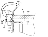
図1に示されるように、ブロア収納部101のうち粒子フィルタ120の端部近傍となる位置には、空気導入室160が形成されている。空気導入室160は、空調ユニット100の外側から、空調ユニット100の内部(具体的にはブロア収納部101の内部)に導入される空気が流れる空間として形成されている。空気導入室160を流れる空気は、粒子フィルタ120を迂回して流れる。
As shown in FIG. 1, an air introducing chamber 160 is formed at a position in the blower housing 101 near the end of the particle filter 120. The air introducing chamber 160 is formed as a space in which air introduced from the outside of the air conditioning unit 100 into the inside of the air conditioning unit 100 (specifically, inside the blower housing 101) flows. The air flowing through the air introduction chamber 160 bypasses the particle filter 120 and flows.
空気導入室160のうち空気の入口となる開口161は、粒子フィルタ120や後述の粒子検知部200よりも上方側となる位置に形成されている。開口161は、空調ユニット100の周囲の空間と、空気導入室160との間を連通させるものである。空気導入室160のうち空気の出口となる開口162は、粒子フィルタ120よりも僅かに下方側となる位置に形成されている。開口162は、空気導入室160と、ブロア収納部101のうち粒子フィルタ120よりも下方側の空間との問を連通させるものである。開口162は、検知部用空気取入口に相当する。尚、上記のような開口161や開口162の位置はあくまで一例である。開口161や開口162は、それぞれ上記とは異なる位置に形成されていてもよい。
An opening 161 serving as an air inlet of the air introduction chamber 160 is formed at a position above the particle filter 120 and a particle detection unit 200 described later. The opening 161 communicates the space around the air conditioning unit 100 with the air introduction chamber 160. The opening 162, which serves as an air outlet, in the air introduction chamber 160 is formed at a position slightly below the particle filter 120. The opening 162 connects the air introducing chamber 160 and a space in the blower housing portion 101 below the particle filter 120. The opening 162 corresponds to the air intake for the detection unit. The positions of the openings 161 and 162 as described above are merely examples. The openings 161 and 162 may be formed at positions different from the above.
空調制御部40について説明する。図1に示す空調制御部40は、空調ユニット100を制御する制御装置である。具体的に、空調制御部40は、半導体メモリなどの非遷移的実体的記憶媒体で構成された記憶部とプロセッサとを含んだ電子制御装置である。空調制御部40は、その記憶部に格納されたコンピュータプログラムを実行する。このコンピュータプログラムが実行されることで、コンピュータプログラムに対応する方法が実行される。
The air conditioning control unit 40 will be described. The air conditioning control unit 40 illustrated in FIG. 1 is a control device that controls the air conditioning unit 100. Specifically, the air conditioning control unit 40 is an electronic control device including a storage unit configured by a non-transitional physical storage medium such as a semiconductor memory and a processor. The air conditioning control unit 40 executes the computer program stored in the storage unit. By executing this computer program, the method corresponding to the computer program is executed.
また、空調制御部40は空調部150に含まれる各アクチュエータへ制御信号を出力することにより、各アクチュエータの作動を制御する。要するに、空調制御部40は、空調部150に対して種々の空調制御を行う。例えば、上述したブロア130、内外気切替ドア、エアミックスドア、フェイス吹出開口部ドア、フット吹出開口部ドアおよびデフロスタ吹出開口部ドア(いずれも図示せず)は、空調制御部40によって駆動制御される。
Further, the air conditioning control unit 40 controls the operation of each actuator by outputting a control signal to each actuator included in the air conditioning unit 150. In short, the air conditioning control unit 40 performs various air conditioning controls on the air conditioning unit 150. For example, the blower 130, the inside/outside air switching door, the air mix door, the face outlet opening door, the foot outlet opening door, and the defroster outlet opening door (none of which are shown) are drive-controlled by the air conditioning controller 40. It
また、図1に示すように、空調制御部40には、例えば、粒子検知部200などのセンサ類やドア等のアクチュエータのほか、操作部41および表示部42が接続されている。
Further, as shown in FIG. 1, the air conditioning control unit 40 is connected with, for example, sensors such as the particle detection unit 200 and actuators such as doors, as well as an operation unit 41 and a display unit 42.
操作部41は、空調部150から吹き出される空調風の風量や温度等を調整する際に乗員により操作される操作部である。操作部41は、例えば車両のインストルメントパネルに配置されている。操作部41では、例えば空調風の風量、車室内の目標室温、及び空調風の吹出口等を設定することができる。また、操作部41では、空調風の風量調整、空調風の温度調整および内気循環または外気導入の選択が自動的に行われる自動空調モードを設定することもできる。操作部41は、これらの設定を示す情報、すなわち操作装置44に対して為された乗員操作を示す操作情報を、空調制御部40に出力する。また、空調制御部40は、粒子検知部200の出力信号に基づいて車室内の空気中における粒子の濃度を算出し、算出した粒子の濃度を、例えば、メータ内に配置された表示部42に表示させる処理も行う。
The operation unit 41 is an operation unit operated by an occupant when adjusting the air volume, temperature, etc. of the conditioned air blown out from the air conditioning unit 150. The operation unit 41 is arranged, for example, on an instrument panel of a vehicle. In the operation unit 41, for example, the air volume of the conditioned air, the target room temperature in the passenger compartment, the outlet of the conditioned air, etc. can be set. Further, in the operation unit 41, it is possible to set an automatic air conditioning mode in which air volume adjustment of air conditioning air, temperature adjustment of air conditioning air, and selection of inside air circulation or introduction of outside air are automatically performed. The operation unit 41 outputs information indicating these settings, that is, operation information indicating an occupant operation performed on the operation device 44, to the air conditioning control unit 40. Further, the air conditioning control unit 40 calculates the concentration of particles in the air in the vehicle compartment based on the output signal of the particle detection unit 200, and the calculated concentration of particles is displayed on, for example, the display unit 42 arranged in the meter. It also performs the process of displaying.
ブロア130が駆動されているときには、ブロア130の吸引力により、空気導入室160の空気は開口162を通ってブロア130側に排出される。これを補うように、外部の空気は開口161を通って空気導入室160に流入する。このため、本実施形態における空気導入室160の内部では、第1開口231よりも上方側となる位置(開口161)から下方側に向けて空気が流れることとなる。
When the blower 130 is driven, the suction force of the blower 130 causes the air in the air introduction chamber 160 to be discharged to the blower 130 side through the opening 162. To compensate for this, outside air flows into the air introduction chamber 160 through the opening 161. For this reason, inside the air introduction chamber 160 in the present embodiment, air flows downward from the position (opening 161) above the first opening 231.
ブロア収納部101は、車両のうちインストルメントパネルの内側に配置されている。インストルメントパネルの内側の空間、すなわち、空気導入室160の外側の空間は、車室内と繋がっている。このため、開口161から空気導入室160に流入する空気は、車室内の空気となっている。
The blower storage section 101 is arranged inside the instrument panel of the vehicle. The space inside the instrument panel, that is, the space outside the air introduction chamber 160, is connected to the vehicle interior. Therefore, the air flowing into the air introduction chamber 160 from the opening 161 is the air in the vehicle compartment.
図1に示されるように、空調ユニット100のうち空気導入室160が形成されている部分は、粒子検知部200が取り付けられる部分となっている。粒子検知部200は、空気導入室160のうち側方の部分を形成するように、ブロア収納部101に対して外側から取り付けられている。粒子検知部200の上端の位置は、開口161よりも低い位置となっている。
As shown in FIG. 1, the portion of the air conditioning unit 100 where the air introduction chamber 160 is formed is the portion to which the particle detection unit 200 is attached. The particle detector 200 is attached to the blower housing 101 from the outside so as to form a side portion of the air introduction chamber 160. The position of the upper end of the particle detector 200 is lower than the opening 161.
粒子検知部200は、空気中における粒子の濃度を測定するためのセンサユニットである。粒子検知部200は、図4に示すように、発光素子211を有する発光部210と、受光素子221を有する受光部220と、を有している。
The particle detection unit 200 is a sensor unit for measuring the concentration of particles in the air. As shown in FIG. 4, the particle detection unit 200 has a light emitting unit 210 having a light emitting element 211 and a light receiving unit 220 having a light receiving element 221.
発光部210から発せられた光の一部は、粒子検知部200の内部に導入された空気中の粒子によって散乱され、更にその一部が受光部220によって検知される。粒子検知部200は、受光部220によって検知された光の光量に基づいて、空気中における粒子の有無や濃度を検知するように構成されている。
A part of the light emitted from the light emitting section 210 is scattered by particles in the air introduced into the particle detecting section 200, and a part of the light is detected by the light receiving section 220. The particle detecting unit 200 is configured to detect the presence or absence and the concentration of particles in the air based on the amount of light detected by the light receiving unit 220.
粒子検知部200は、図3に示されるようにセンサケース230を有している。センサケース230は、上記の発光部210、受光部220、センサブロワ240等を内部に収容する容器であって、略直方体状に形成されている。センサケース230のうち空気導入室160を形成する面には、第1開口231と第2開口232とがそれぞれ形成されている。
The particle detection unit 200 has a sensor case 230 as shown in FIG. The sensor case 230 is a container that houses the light emitting unit 210, the light receiving unit 220, the sensor blower 240, and the like therein, and is formed in a substantially rectangular parallelepiped shape. A first opening 231 and a second opening 232 are formed on the surface of the sensor case 230 that forms the air introduction chamber 160.
第1開口231は、空気導入室160からの空気が流入するように形成された開口である。第2開口232は、上記のように、空気導入室160へと空気を排出するために形成された開口である。本実施形態における第2開口232は、第1開口231よりも上方側となる位置に形成されている。
The first opening 231 is an opening formed so that the air from the air introducing chamber 160 flows in. The second opening 232 is an opening formed to discharge the air to the air introduction chamber 160, as described above. The second opening 232 in the present embodiment is formed at a position above the first opening 231.
また、図5に示すように、粒子検知部200は、センサケース230の内部に導入する空気の流量を調整するセンサブロワ240を有している。発光部210、受光部220およびセンサブロワ240は、センサケース230の内部に配置されている。
Further, as shown in FIG. 5, the particle detection unit 200 has a sensor blower 240 that adjusts the flow rate of the air introduced into the sensor case 230. The light emitting unit 210, the light receiving unit 220, and the sensor blower 240 are arranged inside the sensor case 230.
センサブロワ240は、後述する空調制御部40からの指示に応じて動作する。センサブロワ240は、空気導入室160を流れる空気を第1開口231からセンサケース230の内部に吸い込む。センサブロワ240の最大吸込能力は、ブロア130の最大吸込能力よりも小さくなっている。
The sensor blower 240 operates according to an instruction from the air conditioning control unit 40 described later. The sensor blower 240 sucks the air flowing through the air introduction chamber 160 into the sensor case 230 through the first opening 231. The maximum suction capacity of the sensor blower 240 is smaller than the maximum suction capacity of the blower 130.
粒子検知部200は、第1開口231を通ってセンサケース230の内側へと流入した空気中における粒子の濃度を測定する。当該空気は、既に述べたように車室内の空気である。センサケース230に吸い込まれた空気は、第2開口232から空気導入室160へと排出される。
The particle detection unit 200 measures the concentration of particles in the air that has flowed into the sensor case 230 through the first opening 231. The air is the air in the vehicle compartment as described above. The air sucked into the sensor case 230 is discharged into the air introduction chamber 160 through the second opening 232.
ところで、センサブロワ240の吸込能力を大きくすれば、車両の乗員の体付近の空気を速やかにセンサケース230内に吸い込むことが可能である。しかし、センサブロワ240の吸込能力を大きくすると、流速増加伴う乱流が発生してしまい、粒子の濃度を精度良く検出することができない。
By the way, if the suction capacity of the sensor blower 240 is increased, the air around the body of the vehicle occupant can be quickly sucked into the sensor case 230. However, if the suction capacity of the sensor blower 240 is increased, turbulent flow is generated with an increase in flow velocity, and the particle concentration cannot be detected accurately.
そこで、本実施形態の車両用空調装置10は、吸込能力の大きなブロア130の作動によってブロア収納部101の内部に吸い込まれる空気の一部をセンサケース230内に導入するセンサ導入口を有している。このセンサ導入口は、第1開口231に相当する。
Therefore, the vehicle air conditioner 10 of the present embodiment has a sensor introduction port for introducing a part of the air sucked into the blower housing portion 101 into the sensor case 230 by the operation of the blower 130 having a large suction capacity. There is. This sensor inlet corresponds to the first opening 231.
ここで、内外気切り換えドアの動作によって、内気入口111からブロア収納部101に車室内の内気が導入されるようになっているものとする。ブロア130が作動を開始すると、図5に示すように、内気入口111から粒子フィルタ120およびブロア収納部101を通って内気がブロア130に吸い込まれる。
Here, it is assumed that the inside air in the vehicle compartment is introduced from the inside air inlet 111 to the blower storage unit 101 by the operation of the inside/outside air switching door. When the blower 130 starts operating, the inside air is sucked into the blower 130 from the inside air inlet 111 through the particle filter 120 and the blower housing portion 101, as shown in FIG.
この際、ブロア収納部101の内部に吸い込まれる空気の一部が空気導入室160に流入する。そして、空気導入室160に流入した空気の一部が第1開口231からセンサケース230内に導入される。粒子検知部200は、第1開口231を通ってセンサケース230の内側へと流入した空気中における粒子の濃度を測定する。
At this time, part of the air sucked into the blower storage unit 101 flows into the air introduction chamber 160. Then, a part of the air flowing into the air introducing chamber 160 is introduced into the sensor case 230 through the first opening 231. The particle detection unit 200 measures the concentration of particles in the air that has flowed into the sensor case 230 through the first opening 231.
したがって、センサブロワ240の吸込能力を大きくすることなく、シートに着座した乗員の体付近の遠方の空気に含まれる精度良く、かつ、応答性良く粒子の濃度を検出することが可能となる。
Therefore, without increasing the suction capacity of the sensor blower 240, it is possible to detect the concentration of particles contained in the air in the distance near the body of the occupant seated on the seat with high accuracy and responsiveness.
なお、センサケース230に吸い込まれた空気は、第2開口232から空気導入室160へと排出され、ブロア130に吸い込まれる。
The air sucked into the sensor case 230 is discharged from the second opening 232 into the air introduction chamber 160 and sucked into the blower 130.
本実施形態の車両用空調装置10は、さらに、センサブロワ240の作動によっても、空気導入室160からセンサケース230内に空気が導入される。すなわち、本実施形態の車両用空調装置10は、ブロア130の作動に加えてセンサブロワ240の作動によっても、空気導入室160からセンサケース230内に空気が導入される。したがって、乱流を発生させることなく、精度良く、かつ、応答性良く粒子の濃度を検出することができる。
In the vehicle air conditioner 10 of this embodiment, air is further introduced from the air introduction chamber 160 into the sensor case 230 by the operation of the sensor blower 240. That is, in the vehicle air conditioner 10 of the present embodiment, air is introduced into the sensor case 230 from the air introduction chamber 160 not only by the operation of the blower 130 but also by the operation of the sensor blower 240. Therefore, it is possible to detect the particle concentration with high accuracy and responsiveness without generating turbulence.
ところで、内外気切り換えドアの動作によって内気入口111からブロア収納部101の内部に車室内の内気が導入されるようになっていても、車両の走行速度が速いと車両に設けられたファイヤーウォールの隙間等から車室内に多くの外気が入り込んでしまう。
By the way, even if the inside air in the vehicle compartment is introduced from the inside air inlet 111 into the inside of the blower storage unit 101 by the operation of the inside/outside air switching door, if the traveling speed of the vehicle is high, the speed of the firewall installed in the vehicle is increased. A large amount of outside air enters the passenger compartment through gaps.
そこで、本実施形態の空調制御部40は、車両の走行速度が速くなるほど、ブロア収納部101の内部に吸い込まれる空気の流量を多くするようブロア130を制御する。これにより、乗員の体付近の空気がセンサケース230に導入されやすくなるため、精度良く乗員の体付近の空気中における粒子の濃度を検出することができる。
Therefore, the air conditioning control unit 40 of the present embodiment controls the blower 130 so that the flow rate of the air sucked into the blower storage unit 101 increases as the traveling speed of the vehicle increases. As a result, the air near the body of the occupant is easily introduced into the sensor case 230, so that the concentration of particles in the air near the body of the occupant can be accurately detected.
また、車格によってブロア130の吸込能力は異なる。このため、本実施形態の空調制御部40は、ブロア130の吸込能力の小さな車両では、ブロア130の吸込能力の大きな車両と比較して、よりセンサケース230に導入される空気の流量を多くするようセンサブロワ240を制御する。
Also, the suction capacity of the blower 130 differs depending on the vehicle class. Therefore, the air conditioning control unit 40 of the present embodiment increases the flow rate of air introduced into the sensor case 230 in a vehicle with a small suction capacity of the blower 130, compared with a vehicle with a large suction capacity of the blower 130. The sensor blower 240 is controlled so that
また、車両1のシート3の位置が車両前方にある場合、乗員の体によって車両用空調装置10に向かって流れる空気流が遮られやすい。このため、本実施形態の空調制御部40は、シート3の位置を示す信号に基づいて車両1のシート3の位置が所定位置より車両前方にあることを判定した場合、よりブロア収納部101の内部に吸い込まれる空気の流量をより多くするようブロア130を制御する。
Further, when the position of the seat 3 of the vehicle 1 is in front of the vehicle, the air flow flowing toward the vehicle air conditioning system 10 is easily blocked by the body of the occupant. For this reason, when the air conditioning control unit 40 of the present embodiment determines that the position of the seat 3 of the vehicle 1 is ahead of the predetermined position of the vehicle based on the signal indicating the position of the seat 3, the air conditioning control unit 40 of the blower storage unit 101 is further operated. The blower 130 is controlled to increase the flow rate of the air sucked into the inside.
また、フェイス吹き出し部152から空気を送風するフェイスモード、主としてフット吹き出し部153から空気を送風するフットモード等のモードによって車室内の空気の流れが異なる。このため、本実施形態の空調制御部40は、モードに応じてセンサケース230に導入される空気の流量が適量となるようセンサブロワ240を制御する。
Also, the flow of air in the vehicle compartment varies depending on modes such as a face mode in which air is blown from the face blowing section 152 and a foot mode in which air is blown mainly from the foot blowing section 153. Therefore, the air conditioning control unit 40 of the present embodiment controls the sensor blower 240 so that the flow rate of the air introduced into the sensor case 230 becomes an appropriate amount according to the mode.
また、フェイス吹き出し部152を閉じるドアがフェイス吹き出し部152を閉じているか否かによって車室内の空気の流れが異なる。このため、本実施形態の空調制御部40は、フェイス吹き出し部152を閉じるドアがフェイス吹き出し部152を閉じているか否かを示す信号に応じてセンサケース230に導入される空気の流量が適量となるようセンサブロワ240を制御する。
Also, the flow of air in the vehicle compartment varies depending on whether or not the door that closes the face blowing section 152 closes the face blowing section 152. Therefore, the air conditioning control unit 40 of the present embodiment determines that the flow rate of the air introduced into the sensor case 230 is an appropriate amount according to the signal indicating whether the door closing the face blowing unit 152 closes the face blowing unit 152. The sensor blower 240 is controlled so that
また、空調ケースの空気流路を左右に区切り、右側空気流路と左側空気流路からそれぞれ吹き出される吹出空気の温度を独立して制御する左右独立温度制御方式の車両用空調装置では、右側空気流路と左側空気流路から吹き出される空気の風量が異なる。このため、本実施形態の空調制御部40は、右側空気流路と左側空気流路からそれぞれ吹き出される吹出空気の風量に応じてセンサケース230に導入される空気の流量が適量となるようセンサブロワ240を制御する。
In addition, the air flow path of the air conditioning case is divided into left and right, and the right and left independent temperature control type vehicle air conditioners that independently control the temperature of the air blown from the right air flow path and the left air flow path The air flow rates of the air blown from the air flow path and the left air flow path are different. Therefore, the air conditioning controller 40 of the present embodiment uses the sensor blower so that the flow rate of the air introduced into the sensor case 230 becomes an appropriate amount according to the air volume of the blown air blown out from the right air passage and the left air passage. Control 240.
また、シートに埋設されたシート空調装置からシートに着座した乗員の体に向けて空調風を吹き出すことにより空調を行う車両では、車室内の空気に対流が生じやすい。このため、本実施形態の空調制御部40は、シート空調装置が作動していない場合には、シート空調装置が作動している場合と比較して。センサケース230に導入される空気の流量がより多くなるようセンサブロワ240を制御する。
Also, in a vehicle that performs air conditioning by blowing out conditioned air from the seat air conditioner embedded in the seat toward the body of an occupant seated on the seat, convection is likely to occur in the air in the passenger compartment. Therefore, the air conditioning control unit 40 of the present embodiment compares the case where the seat air conditioning system is not operating with the case where the seat air conditioning system is operating. The sensor blower 240 is controlled so that the flow rate of air introduced into the sensor case 230 is increased.
また、車両の後席用に配置されたリア空調装置から後席の乗員の体に向けて冷風を吹き出すことにより空調を行う車両では、車室内の空気に対流が生じやすい。このため、本実施形態の空調制御部40は、リア空調装置が作動していない場合には、シート空調装置が作動している場合と比較して。センサケース230に導入される空気の流量がより多くなるようセンサブロワ240を制御する。
Also, in a vehicle that performs air conditioning by blowing cool air toward the body of a passenger in the rear seat from the rear air conditioner arranged for the rear seats of the vehicle, convection is likely to occur in the air in the passenger compartment. Therefore, the air conditioning control unit 40 of the present embodiment compares the case where the rear air conditioner is not operating with the case where the seat air conditioner is operating. The sensor blower 240 is controlled so that the flow rate of air introduced into the sensor case 230 is increased.
以上、説明したように、車両用空調装置は、車室内に送風される空気が流れる空気通路を形成する空調ケース101、140、150を備える。そして車両用空調装置は、空調ケース101、140、150の内部に配置されて空調ケース101、140、150の内部に空気を吸い込むブロア130を備えている。
As described above, the vehicle air conditioner includes the air conditioning cases 101, 140, and 150 that form the air passages through which the air blown into the vehicle interior flows. The vehicle air conditioner includes a blower 130 that is arranged inside the air conditioning cases 101, 140, 150 and sucks air into the air conditioning cases 101, 140, 150.
さらに、空気に含まれる粒子状物質の粒子濃度を検出する粒子検知部200を備えている。また、粒子検知部200は、空気に光を照射する発光部210と、発光部210が照射した光が粒子状物質に当たって散乱した散乱光を受光する受光部220と、発光部210および受光部220を収納するセンサケース230を有している。
Further, a particle detector 200 for detecting the particle concentration of the particulate matter contained in the air is provided. Further, the particle detecting unit 200 includes a light emitting unit 210 that irradiates air with light, a light receiving unit 220 that receives scattered light that is scattered by the light emitted by the light emitting unit 210 hitting a particulate matter, and the light emitting unit 210 and the light receiving unit 220. It has a sensor case 230 for housing the.
そして、センサケース230には、ブロア130の作動によって空調ケース101、140、150の内部に吸い込まれる空気の一部をセンサケース230の内部に導入するセンサ導入口としての第1開口231が形成されている。
Then, the sensor case 230 is formed with a first opening 231 as a sensor introduction port for introducing a part of the air sucked into the air conditioning cases 101, 140 and 150 into the sensor case 230 by the operation of the blower 130. ing.
このような構成によれば、センサケース230には、ブロア130の作動によって空調ケース101、140、150の内部に吸い込まれる空気の一部をセンサケース230の内部に導入するセンサ導入口としての第1開口231が形成されている。したがって、遠方の空気に含まれる粒子状物質の濃度をより精度良く、かつ、応答性良く検出することができる。
According to such a configuration, the sensor case 230 has a first sensor introduction port as a sensor introduction port for introducing a part of the air sucked into the air conditioning cases 101, 140 and 150 by the operation of the blower 130 into the sensor case 230. One opening 231 is formed. Therefore, the concentration of the particulate matter contained in the distant air can be detected more accurately and with good responsiveness.
また、粒子検知部200は、空調ケース101、140、150の内部に吸い込まれる空気の一部をセンサ導入口としての第1開口231を介してセンサケース230の内部に吸い込むセンサブロワ240を有している。
Further, the particle detection unit 200 has a sensor blower 240 that sucks a part of the air sucked into the air conditioning cases 101, 140, and 150 into the sensor case 230 through the first opening 231 serving as a sensor inlet. There is.
したがって、センサブロワ240の吸い込みによって、さらに、空調ケース101、140、150の内部に吸い込まれる空気の一部をセンサケース230の内部に導入することが可能である。
Therefore, by sucking the sensor blower 240, it is possible to further introduce a part of the air sucked into the air conditioning cases 101, 140, 150 into the sensor case 230.
また、センサブロワ240は、センサケース230の内部に配置されている。このように、センサケース230の内部に配置されたセンサブロワ240によって、空調ケース101、140、150の内部に吸い込まれる空気の一部をセンサケース230の内部に導入することができる。
Further, the sensor blower 240 is arranged inside the sensor case 230. In this way, the sensor blower 240 disposed inside the sensor case 230 can introduce a part of the air sucked into the air conditioning cases 101, 140, and 150 into the sensor case 230.
また、空調ケース101、140、150のうちセンサケース230が取り付けられる部分には、空調ケース101、140、150の外側から空調ケース101、140、150の内部に導入される空気が流れる空間である空気導入室160が形成されている。そして、センサブロワ240は、空気導入室160を流れる空気の一部をセンサケース230の内部に吸い込む。
A portion of the air conditioning case 101, 140, 150 to which the sensor case 230 is attached is a space in which air introduced from the outside of the air conditioning case 101, 140, 150 into the air conditioning case 101, 140, 150 flows. An air introducing chamber 160 is formed. Then, the sensor blower 240 sucks a part of the air flowing through the air introducing chamber 160 into the sensor case 230.
このように、空気導入室160を流れる空気の一部をセンサケース230の内部に吸い込むようにセンサブロワ240を設けることができる。
In this way, the sensor blower 240 can be provided so as to suck a part of the air flowing through the air introduction chamber 160 into the sensor case 230.
(第2実施形態)
第2実施形態に係る車両用空調装置について図6~図8を用いて説明する。上記第1実施形態の車両用空調装置10は、ブロア収納部101のうち粒子フィルタ120の端部近傍となる位置に空気導入室160が形成され、この空気導入室160を流れる空気の一部が粒子検知部200のセンサケース230に導入されるようになっている。 (Second embodiment)
A vehicle air conditioner according to the second embodiment will be described with reference to FIGS. 6 to 8. In thevehicle air conditioner 10 of the first embodiment, the air introduction chamber 160 is formed in the blower storage portion 101 at a position near the end of the particle filter 120, and a part of the air flowing in the air introduction chamber 160 is formed. It is adapted to be introduced into the sensor case 230 of the particle detector 200.
第2実施形態に係る車両用空調装置について図6~図8を用いて説明する。上記第1実施形態の車両用空調装置10は、ブロア収納部101のうち粒子フィルタ120の端部近傍となる位置に空気導入室160が形成され、この空気導入室160を流れる空気の一部が粒子検知部200のセンサケース230に導入されるようになっている。 (Second embodiment)
A vehicle air conditioner according to the second embodiment will be described with reference to FIGS. 6 to 8. In the
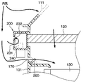
これに対し、本実施形態の車両用空調装置10は、ブロア収納部101に空気導入室160が形成されておらず、粒子検知部200は、内気入口111に導入される空気の一部が粒子検知部200のセンサケース230に導入されるようになっている。
On the other hand, in the vehicle air conditioner 10 of the present embodiment, the air introduction chamber 160 is not formed in the blower storage part 101, and the particle detection part 200 is configured such that a part of the air introduced into the inside air inlet 111 is a particle. It is adapted to be introduced into the sensor case 230 of the detection unit 200.
図7に示すように、粒子検知部200は、センサケース230の内部に導入する空気の流量を調整するセンサブロワ240を有している。センサブロワ240は、センサケース230の内部に配置されている。なお、図7中には示してないが、発光部210および受光部220についてもセンサケース230の内部に配置されている。
As shown in FIG. 7, the particle detection unit 200 has a sensor blower 240 that adjusts the flow rate of air introduced into the sensor case 230. The sensor blower 240 is arranged inside the sensor case 230. Although not shown in FIG. 7, the light emitting unit 210 and the light receiving unit 220 are also arranged inside the sensor case 230.
センサブロワ240は、後述する空調制御部40からの指示に応じて動作する。センサブロワ240は、内気入口111に導入される内気の一部を第1開口231からセンサケース230の内部に吸い込む。センサブロワ240の最大吸込能力は、ブロア130の最大吸込能力よりも小さくなっている。
The sensor blower 240 operates according to an instruction from the air conditioning control unit 40 described later. The sensor blower 240 sucks a part of the inside air introduced into the inside air inlet 111 into the sensor case 230 through the first opening 231. The maximum suction capacity of the sensor blower 240 is smaller than the maximum suction capacity of the blower 130.
粒子検知部200は、第1開口231を通ってセンサケース230の内側へと流入した空気中における粒子の濃度を測定する。当該空気は、既に述べたように車室内の空気である。センサケース230の内部に吸い込まれた空気は、第2開口232からセンサケース230の外部に排出される。
The particle detection unit 200 measures the concentration of particles in the air that has flowed into the sensor case 230 through the first opening 231. The air is the air in the vehicle compartment as described above. The air sucked into the sensor case 230 is discharged to the outside of the sensor case 230 through the second opening 232.
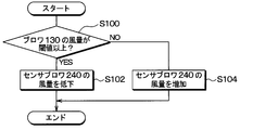
本実施形態の空調制御部40は、ブロア130の送風風量に応じてセンサブロワ240の風量を調整する処理を実施する。この処理のフローチャートを図8に示す。空調制御部40は、周期的に図8に示す処理を実施する。
The air conditioning control unit 40 of the present embodiment performs a process of adjusting the air volume of the sensor blower 240 according to the air volume of the blower 130. A flowchart of this process is shown in FIG. The air conditioning control unit 40 periodically executes the processing shown in FIG.
まず、空調制御部40は、S100にて、ブロア130の送風風量が閾値以上であるか否かを判定する。具体的には、ブロア130に供給する電圧に基づいてブロア130の送風風量を推定し、この送風風量が閾値以上であるか否かを判定する。
First, the air conditioning controller 40 determines in S100 whether or not the blown air volume of the blower 130 is equal to or greater than a threshold value. Specifically, the blown air volume of the blower 130 is estimated based on the voltage supplied to the blower 130, and it is determined whether this blown air volume is equal to or more than a threshold value.
ここで、ブロア130の送風風量が閾値以上であると判定された場合、空調制御部40は、S102にて、センサブロワ240の風量を低下させる。これにより、センサケース230内に過剰な空気が導入されるのを防止することができる。
Here, when it is determined that the blown air volume of the blower 130 is equal to or greater than the threshold value, the air conditioning control unit 40 reduces the air volume of the sensor blower 240 in S102. As a result, it is possible to prevent excessive air from being introduced into the sensor case 230.
また、ブロア130の送風風量が閾値未満であると判定された場合、空調制御部40は、S104にて、センサブロワ240の風量を増加させる。これにより、センサケース230内に適量の空気を導入することが可能となる。
When it is determined that the blown air volume of the blower 130 is less than the threshold value, the air conditioning control unit 40 increases the air volume of the sensor blower 240 in S104. This makes it possible to introduce an appropriate amount of air into the sensor case 230.
本実施形態では、上記第1実施形態と共通の構成から奏される同様の効果を上記第1実施形態と同様に得ることができる。
In the present embodiment, the same effect as that obtained from the configuration common to the first embodiment can be obtained similarly to the first embodiment.
また、ステップS100に対応する風量判定部は、送風機の送風風量が閾値以上であるか否かを判定する。また、ステップS102、S104に対応する風量調整部は、風量判定部により送風機の送風風量が閾値以上であると判定された場合、センサブロワの吸い込み風量を低下させる。また、風量調整部は、風量判定部により送風機の送風風量が閾値未満であると判定された場合、センサブロワの吸い込み風量を増加させる。
Also, the air volume determination unit corresponding to step S100 determines whether or not the air volume of the blower is greater than or equal to a threshold value. In addition, the air volume adjusting unit corresponding to steps S102 and S104 reduces the intake air volume of the sensor blower when the air volume determining unit determines that the air volume of the blower is greater than or equal to the threshold value. In addition, when the air volume determination unit determines that the air volume of the blower is less than the threshold value, the air volume adjustment unit increases the intake air volume of the sensor blower.
このように、風量判定部により送風機の送風風量が閾値以上であると判定された場合、センサブロワの吸い込み風量を低下させ、風量判定部により送風機の送風風量が閾値未満であると判定された場合、センサブロワの吸い込み風量を増加させることができる。
Thus, if the air flow rate of the blower is determined to be equal to or higher than the threshold value by the air flow rate determination unit, the intake air volume of the sensor blower is reduced, and if the air flow rate of the blower is determined to be less than the threshold value by the air flow rate determination unit, It is possible to increase the intake air volume of the sensor blower.
(第3実施形態)
第3実施形態に係る車両用空調装置について図9を用いて説明する。本実施形態の車両用空調装置10は、ブロア収納部101のうち粒子フィルタ120の端部近傍となる位置にブロア収納部101の外側からブロア収納部101の内部に空気を取り入れる検知部用空気取入口170が形成されている。この検知部用空気取入口170を流れる空気の一部が粒子検知部200のセンサケース230に導入される。 (Third Embodiment)
A vehicle air conditioner according to the third embodiment will be described with reference to FIG. Thevehicle air conditioner 10 according to the present embodiment is configured such that the air intake device for the detection unit takes in air from the outside of the blower storage unit 101 to the inside of the blower storage unit 101 at a position near the end of the particle filter 120 in the blower storage unit 101. An inlet 170 is formed. A part of the air flowing through the air intake 170 for the detection unit is introduced into the sensor case 230 of the particle detection unit 200.
第3実施形態に係る車両用空調装置について図9を用いて説明する。本実施形態の車両用空調装置10は、ブロア収納部101のうち粒子フィルタ120の端部近傍となる位置にブロア収納部101の外側からブロア収納部101の内部に空気を取り入れる検知部用空気取入口170が形成されている。この検知部用空気取入口170を流れる空気の一部が粒子検知部200のセンサケース230に導入される。 (Third Embodiment)
A vehicle air conditioner according to the third embodiment will be described with reference to FIG. The
また、本実施形態の車両用空調装置10は、検知部用空気取入口170の開度を調整する開閉ドア250を備えている。開閉ドア250は、ドア部材に相当する。
Further, the vehicle air conditioner 10 of the present embodiment includes an opening/closing door 250 that adjusts the opening degree of the detection unit air intake 170. The opening/closing door 250 corresponds to a door member.
空調制御部40は、センサブロワ240によってセンサケース230に導入される空気の流量を調整するともに、開閉ドア25によってブロア収納部101の外部からブロア収納部101の内部に導入される空気の流量を調整することが可能となっている。
The air conditioning control unit 40 adjusts the flow rate of air introduced into the sensor case 230 by the sensor blower 240 and adjusts the flow rate of air introduced from the outside of the blower storage unit 101 into the inside of the blower storage unit 101 by the opening/closing door 25. It is possible to do.
ドア部材250が検知部用空気取入口170を開いている場合、粒子フィルタ120を通らない空気が検知部用空気取入口170を通って空調部150に導入される。しかし、ドア部材250によって第1開口231を閉じることで、粒子フィルタ120を通らない空気が検知部用空気取入口170を通って空調部150に導入しないようにすることができる。
When the door member 250 opens the air intake 170 for the detection unit, the air that does not pass through the particle filter 120 is introduced into the air conditioning unit 150 through the air intake 170 for the detection unit. However, by closing the first opening 231 with the door member 250, it is possible to prevent the air that does not pass through the particle filter 120 from entering the air conditioning unit 150 through the detection unit air intake 170.
本実施形態では、上記第1実施形態と共通の構成から奏される同様の効果を上記第1実施形態と同様に得ることができる。
In the present embodiment, the same effect as that obtained from the configuration common to the first embodiment can be obtained similarly to the first embodiment.
また、空調ケース101、140、150のうちセンサケース230が取り付けられる部分には、空調ケース101、140、150の外部から空調ケース101、140、150の内部に空気を取り入れる検知部用空気取入口170が形成されている。そして、車両用空調装置10は、検知部用空気取入口170の開度を調整するドア部材250を備えている。
Further, in the portion of the air conditioning case 101, 140, 150 to which the sensor case 230 is attached, an air inlet for a detection unit that takes in air from outside the air conditioning case 101, 140, 150 into the air conditioning case 101, 140, 150. 170 is formed. The vehicle air conditioner 10 includes a door member 250 that adjusts the opening degree of the detection unit air intake 170.
このように、検知部用空気取入口170の開度を調整するドア部材250を備えることで、検知部用空気取入口170を通ってブロア収納部101の内部に空気が導入されないようにすることができる。
As described above, by providing the door member 250 that adjusts the opening degree of the detection unit air intake 170, it is possible to prevent air from being introduced into the blower storage unit 101 through the detection unit air intake 170. You can
(他の実施形態)
(1)上記各実施形態では、センサブロワ240をセンサケース230の内部に配置したが、センサブロワ240をセンサケース230の外部に配置してもよい。例えば、センサブロワ240を空気導入室160に配置して、空調ケースの外側から空気導入室160に空気を吸い込むようにしてもよい。 (Other embodiments)
(1) In each of the above embodiments, thesensor blower 240 is arranged inside the sensor case 230, but the sensor blower 240 may be arranged outside the sensor case 230. For example, the sensor blower 240 may be arranged in the air introducing chamber 160 so that air is sucked into the air introducing chamber 160 from the outside of the air conditioning case.
(1)上記各実施形態では、センサブロワ240をセンサケース230の内部に配置したが、センサブロワ240をセンサケース230の外部に配置してもよい。例えば、センサブロワ240を空気導入室160に配置して、空調ケースの外側から空気導入室160に空気を吸い込むようにしてもよい。 (Other embodiments)
(1) In each of the above embodiments, the
(2)上記第3実施形態の車両用空調装置は、検知部用空気取入口170の開度を調整する開閉ドア250を備えたが、例えば、上記第1実施形態の車両用空調装置についても、開口162の開度を調整する開閉ドアを備えるようにしてもよい。
(2) The vehicle air conditioner of the third embodiment includes the opening/closing door 250 that adjusts the opening degree of the detection unit air intake 170. However, for example, the vehicle air conditioner of the first embodiment described above is also included. An opening/closing door for adjusting the opening of the opening 162 may be provided.
なお、本開示は上記した実施形態に限定されるものではなく、適宜変更が可能である。また、上記各実施形態は、互いに無関係なものではなく、組み合わせが明らかに不可な場合を除き、適宜組み合わせが可能である。また、上記各実施形態において、実施形態を構成する要素は、特に必須であると明示した場合および原理的に明らかに必須であると考えられる場合等を除き、必ずしも必須のものではないことは言うまでもない。また、上記各実施形態において、実施形態の構成要素の個数、数値、量、範囲等の数値が言及されている場合、特に必須であると明示した場合および原理的に明らかに特定の数に限定される場合等を除き、その特定の数に限定されるものではない。また、上記各実施形態において、構成要素等の材質、形状、位置関係等に言及するときは、特に明示した場合および原理的に特定の材質、形状、位置関係等に限定される場合等を除き、その材質、形状、位置関係等に限定されるものではない。
It should be noted that the present disclosure is not limited to the above-described embodiment, and can be modified as appropriate. Further, the above embodiments are not unrelated to each other, and can be appropriately combined unless a combination is obviously impossible. Further, in each of the above-mentioned embodiments, it goes without saying that the elements constituting the embodiment are not necessarily essential unless explicitly stated as being essential and in principle considered to be essential. Yes. Further, in each of the above-described embodiments, when numerical values such as the number of components of the embodiment, numerical values, amounts, ranges, etc. are referred to, it is clearly limited to a particular number and in principle limited to a specific number. The number is not limited to the specific number, except in the case of being performed. Further, in each of the above-described embodiments, when referring to the material, shape, positional relationship, etc. of the constituent elements, etc., unless specifically stated or in principle limited to a specific material, shape, positional relationship, etc. However, the material, shape, positional relationship, etc. are not limited.
(まとめ)
上記各実施形態の一部または全部で示された第1の観点によれば、車両用空調装置は、車室内に送風される空気が流れる空気通路を形成する空調ケースと、空調ケースの内部に配置され、空調ケースの内部に空気を吸い込む送風機と、を備えている。さらに、空気に含まれる粒子状物質の粒子濃度を検出する粒子検知部を備えている。また、粒子検知部は、空気に光を照射する発光部と、発光部が照射した光が粒子状物質に当たって散乱した散乱光を受光する受光部と、発光部および受光部を収納するセンサケースを有している。そして、センサケースには、送風機の作動によって空調ケースの内部に吸い込まれる空気の一部をセンサケースの内部に導入するセンサ導入口が形成されている。 (Summary)
According to the first aspect shown in part or all of each of the above-described embodiments, the vehicle air conditioner includes an air conditioning case that forms an air passage through which air blown into the vehicle interior flows, and an interior of the air conditioning case. And a blower that draws air into the inside of the air conditioning case. Further, a particle detection unit for detecting the particle concentration of the particulate matter contained in the air is provided. In addition, the particle detection unit includes a light emitting unit that irradiates air with light, a light receiving unit that receives scattered light when the light emitted by the light emitting unit hits the particulate matter and is scattered, and a sensor case that houses the light emitting unit and the light receiving unit. Have The sensor case is formed with a sensor introduction port for introducing a part of the air sucked into the air conditioning case into the sensor case by the operation of the blower.
また、第2の観点によれば、粒子検知部は、空調ケースの内部に吸い込まれる空気の一部をセンサ導入口を介してセンサケースの内部に吸い込むセンサブロワを有している。
According to the second aspect, the particle detection unit has a sensor blower that sucks a part of the air sucked into the air conditioning case into the sensor case through the sensor inlet.
したがって、センサブロワの吸い込みによって、さらに、空調ケースの内部に吸い込まれる空気の一部をセンサケースの内部に導入することが可能である。
Therefore, by sucking the sensor blower, it is possible to further introduce a part of the air sucked into the air conditioning case into the sensor case.
また、第3の観点によれば、また、センサブロワは、センサケースの内部に配置されている。このように、センサケースの内部に配置されたセンサブロワによって、空調ケースの内部に吸い込まれる空気の一部をセンサケースの内部に導入することができる。
According to the third aspect, the sensor blower is also arranged inside the sensor case. Thus, the sensor blower arranged inside the sensor case can introduce a part of the air sucked into the air conditioning case into the sensor case.
また、第4の観点によれば、空調ケースのうちセンサケースが取り付けられる部分には、空調ケースの外側から空調ケースの内部に導入される空気が流れる空間である空気導入室が形成されている。そして、センサブロワは、空気導入室を流れる空気の一部をセンサケースの内部に吸い込む。
Further, according to the fourth aspect, an air introduction chamber that is a space in which air introduced from the outside of the air conditioning case into the inside of the air conditioning case flows is formed in a portion of the air conditioning case to which the sensor case is attached. .. Then, the sensor blower sucks a part of the air flowing through the air introduction chamber into the sensor case.
このように、空気導入室を流れる空気の一部をセンサケースの内部に吸い込むようにセンサブロワを設けることができる。
In this way, a sensor blower can be installed so that part of the air flowing through the air introduction chamber is sucked into the sensor case.
また、第5の観点によれば、車両用空調装置は、送風機の送風風量が閾値以上であるか否かを判定する風量判定部を備えている。また、風量判定部により送風機の送風風量が閾値以上であると判定された場合、センサブロワの吸い込み風量を低下させ、風量判定部により送風機の送風風量が閾値未満であると判定された場合、センサブロワの吸い込み風量を増加させる風量調整部を備えている。
Further, according to a fifth aspect, the vehicle air conditioner includes an air volume determination unit that determines whether or not the air volume of the blower is equal to or greater than a threshold value. Further, if the air flow rate of the blower is determined to be equal to or higher than the threshold value by the air flow rate determination unit, the intake air volume of the sensor blower is reduced, and if the air flow rate of the blower is determined to be less than the threshold value by the air flow rate determination unit, the sensor blower It is equipped with an air volume adjustment unit that increases the intake air volume.
このように、風量判定部により送風機の送風風量が閾値以上であると判定された場合、センサブロワの吸い込み風量を低下させ、風量判定部により送風機の送風風量が閾値未満であると判定された場合、センサブロワの吸い込み風量を増加させることができる。
Thus, if the air flow rate of the blower is determined to be equal to or higher than the threshold value by the air flow rate determination unit, the intake air volume of the sensor blower is reduced, and if the air flow rate of the blower is determined to be less than the threshold value by the air flow rate determination unit, It is possible to increase the intake air volume of the sensor blower.
また、第6の観点によれば、空調ケースのうちセンサケースが取り付けられる部分には、空調ケースの外部から空調ケースの内部に空気を取り入れる検知部用空気取入口が形成されている。そして、車両用空調装置は、検知部用空気取入口の開度を調整するドア部材を備えている。
Further, according to the sixth aspect, in the portion of the air conditioning case to which the sensor case is attached, an air inlet for the detection unit that takes in air from the outside of the air conditioning case to the inside of the air conditioning case is formed. The vehicle air conditioner includes a door member that adjusts the opening degree of the detection unit air intake.
このように、検知部用空気取入口の開度を調整するドア部材を備えることで、検知部用空気取入口を通ってブロア収納部の内部に空気が導入されないようにすることができる。
In this way, by providing the door member that adjusts the opening degree of the air intake for the detection unit, it is possible to prevent air from being introduced into the blower storage unit through the air intake for the detection unit.
なお、第1開口231がセンサ導入口に対応し、検知部用空気取入口170および開口162が検知部用空気取入口に対応し、S100の処理が風量判定部に相当し、S102、S104の処理が風量調整部に対応する。
The first opening 231 corresponds to the sensor inlet, the detection unit air intake 170 and the opening 162 correspond to the detection unit air intake, the process of S100 corresponds to the air volume determination unit, and S102 and S104. The processing corresponds to the air volume adjusting unit.
Claims (6)
- 車両用空調装置であって、
車室内に送風される空気が流れる空気通路を形成する空調ケース(101、140、150)と、
前記空調ケースの内部に配置され、前記空調ケースの内部に前記空気を吸い込む送風機(130)と、
前記空気に含まれる粒子状物質の粒子濃度を検出する粒子検知部(200)と、を備え、
前記粒子検知部は、
前記空気に光を照射する発光部(210)と、
前記発光部が照射した光が前記粒子状物質に当たって散乱した散乱光を受光する受光部(220)と、
前記発光部および前記受光部を収納するセンサケース(230)を有し、
前記センサケースには、前記送風機の作動によって前記空調ケースの内部に吸い込まれる前記空気の一部を前記センサケースの内部に導入するセンサ導入口(231)が形成されている車両用空調装置。 A vehicle air conditioner,
An air-conditioning case (101, 140, 150) forming an air passage through which the air blown into the vehicle interior flows;
A blower (130) disposed inside the air-conditioning case and sucking the air into the air-conditioning case;
A particle detector (200) for detecting the particle concentration of the particulate matter contained in the air,
The particle detector is
A light emitting unit (210) for irradiating the air with light,
A light receiving unit (220) for receiving scattered light that is emitted by the light emitting unit and is scattered by hitting the particulate matter;
A sensor case (230) accommodating the light emitting unit and the light receiving unit,
A vehicle air conditioner in which a sensor introduction port (231) for introducing a part of the air sucked into the inside of the air conditioning case by the operation of the blower into the inside of the sensor case is formed in the sensor case. - 前記粒子検知部は、前記空調ケースの内部に吸い込まれる前記空気の一部を前記センサ導入口を介して前記センサケースの内部に吸い込むセンサブロワ(240)を有している請求項1に記載の車両用空調装置。 The vehicle according to claim 1, wherein the particle detection unit includes a sensor blower (240) that sucks a part of the air sucked into the air conditioning case into the sensor case through the sensor inlet. Air conditioner.
- 前記センサブロワは、前記センサケースの内部に配置されている請求項2に記載の車両用空調装置。 The vehicle air conditioner according to claim 2, wherein the sensor blower is arranged inside the sensor case.
- 前記空調ケースのうち前記センサケースが取り付けられる部分には、前記空調ケースの外側から前記空調ケースの内部に導入される前記空気が流れる空間である空気導入室(160)が形成されており、
前記センサブロワは、前記空気導入室を流れる前記空気の一部を前記センサケースの内部に吸い込む請求項2または3に記載の車両用空調装置。 An air introduction chamber (160), which is a space in which the air introduced from the outside of the air conditioning case into the inside of the air conditioning case flows, is formed in a portion of the air conditioning case to which the sensor case is attached.
The vehicle air conditioner according to claim 2 or 3, wherein the sensor blower sucks a part of the air flowing through the air introducing chamber into the sensor case. - 前記送風機の送風風量が閾値以上であるか否かを判定する風量判定部(S100)と、
前記風量判定部により前記送風機の送風風量が閾値以上であると判定された場合、前記センサブロワの吸い込み風量を低下させ、前記風量判定部により前記送風機の送風風量が閾値未満であると判定された場合、前記センサブロワの吸い込み風量を増加させる風量調整部(S102、S104)と、を備えた請求項2ないし4のいずれか1つに記載の車両用空調装置。 An air volume determination unit (S100) that determines whether or not the air volume of the blower is equal to or greater than a threshold value;
When the air flow rate of the blower is determined to be equal to or higher than the threshold value by the air flow rate determination unit, the suction air volume of the sensor blower is reduced, and the air flow rate of the blower is determined to be less than the threshold value by the air flow rate determination unit. The air conditioner for a vehicle according to any one of claims 2 to 4, further comprising: an air volume adjusting unit (S102, S104) that increases an air volume sucked in by the sensor blower. - 前記空調ケースのうち前記センサケースが取り付けられる部分には、前記空調ケースの外部から前記空調ケースの内部に前記空気を取り入れる検知部用空気取入口(170、162)が形成されており、
前記検知部用空気取入口の開度を調整するドア部材(250)を備えた請求項1ないし5のいずれか1つに記載の車両用空調装置。 An air inlet (170, 162) for a detection unit that takes in the air from the outside of the air conditioning case to the inside of the air conditioning case is formed in a portion of the air conditioning case to which the sensor case is attached.
The vehicle air conditioner according to any one of claims 1 to 5, further comprising a door member (250) that adjusts an opening degree of the air intake port for the detection unit.
Priority Applications (1)
| Application Number | Priority Date | Filing Date | Title |
|---|---|---|---|
| CN201980083435.8A CN113242807B (en) | 2018-12-20 | 2019-11-21 | Air conditioner for vehicle |
Applications Claiming Priority (2)
| Application Number | Priority Date | Filing Date | Title |
|---|---|---|---|
| JP2018238528A JP7234619B2 (en) | 2018-12-20 | 2018-12-20 | vehicle air conditioner |
| JP2018-238528 | 2018-12-20 |
Publications (1)
| Publication Number | Publication Date |
|---|---|
| WO2020129534A1 true WO2020129534A1 (en) | 2020-06-25 |
Family
ID=71102131
Family Applications (1)
| Application Number | Title | Priority Date | Filing Date |
|---|---|---|---|
| PCT/JP2019/045666 WO2020129534A1 (en) | 2018-12-20 | 2019-11-21 | Vehicle air-conditioning device |
Country Status (3)
| Country | Link |
|---|---|
| JP (1) | JP7234619B2 (en) |
| CN (1) | CN113242807B (en) |
| WO (1) | WO2020129534A1 (en) |
Citations (4)
| Publication number | Priority date | Publication date | Assignee | Title |
|---|---|---|---|---|
| JP2017116147A (en) * | 2015-12-22 | 2017-06-29 | パナソニックIpマネジメント株式会社 | Air cleaner |
| JP2017122554A (en) * | 2016-01-08 | 2017-07-13 | 株式会社Cmc | Device functioning as air cleaner and electric fan and control method of the same |
| JP2018099937A (en) * | 2016-12-19 | 2018-06-28 | 株式会社デンソー | Air conditioner for vehicle |
| JP2018141679A (en) * | 2017-02-27 | 2018-09-13 | パナソニックIpマネジメント株式会社 | Dust sensor |
Family Cites Families (5)
| Publication number | Priority date | Publication date | Assignee | Title |
|---|---|---|---|---|
| CN204358868U (en) * | 2014-12-18 | 2015-05-27 | 南京协众汽车空调集团有限公司 | Based on the vehicle environment protection air-conditioning system of PM2.5 monitoring |
| WO2016170862A1 (en) * | 2015-04-24 | 2016-10-27 | 株式会社デンソー | Vehicle air-conditioning apparatus |
| WO2017082074A1 (en) * | 2015-11-12 | 2017-05-18 | 株式会社デンソー | Air conditioning device for vehicle |
| KR101795173B1 (en) * | 2015-12-02 | 2017-11-07 | 현대자동차주식회사 | Apparatus for sensing interior temperature and dust of vehicle |
| JP6631487B2 (en) * | 2016-12-02 | 2020-01-15 | 株式会社デンソー | Vehicle air conditioner |
-
2018
- 2018-12-20 JP JP2018238528A patent/JP7234619B2/en active Active
-
2019
- 2019-11-21 CN CN201980083435.8A patent/CN113242807B/en active Active
- 2019-11-21 WO PCT/JP2019/045666 patent/WO2020129534A1/en active Application Filing
Patent Citations (4)
| Publication number | Priority date | Publication date | Assignee | Title |
|---|---|---|---|---|
| JP2017116147A (en) * | 2015-12-22 | 2017-06-29 | パナソニックIpマネジメント株式会社 | Air cleaner |
| JP2017122554A (en) * | 2016-01-08 | 2017-07-13 | 株式会社Cmc | Device functioning as air cleaner and electric fan and control method of the same |
| JP2018099937A (en) * | 2016-12-19 | 2018-06-28 | 株式会社デンソー | Air conditioner for vehicle |
| JP2018141679A (en) * | 2017-02-27 | 2018-09-13 | パナソニックIpマネジメント株式会社 | Dust sensor |
Also Published As
| Publication number | Publication date |
|---|---|
| CN113242807B (en) | 2024-02-27 |
| JP7234619B2 (en) | 2023-03-08 |
| CN113242807A (en) | 2021-08-10 |
| JP2020100209A (en) | 2020-07-02 |
Similar Documents
| Publication | Publication Date | Title |
|---|---|---|
| JP4675229B2 (en) | Air conditioning system for vehicles | |
| CN105307881A (en) | Method for controlling a ventilation/air-conditioning system of a vehicle, and vehicle having such a ventilation/air-conditioning system | |
| WO2019045009A1 (en) | Dust concentration detection device | |
| EP3104092A1 (en) | Indoor unit for air conditioner | |
| CN113498386B (en) | Particle concentration detection device | |
| WO2020129534A1 (en) | Vehicle air-conditioning device | |
| JP6920901B2 (en) | Air conditioner | |
| JP5511238B2 (en) | Aspirator and vehicle air conditioner using the same | |
| WO2020090503A1 (en) | Pm sensor | |
| WO2020149065A1 (en) | Pm sensor | |
| JP6791049B2 (en) | Vehicle air conditioner | |
| JP2020121698A (en) | Air conditioner for vehicle | |
| EP4230451A1 (en) | Vehicular air conditioner | |
| CN111032389B (en) | Air conditioner for vehicle | |
| US20190016192A1 (en) | Vehicular air conditioner | |
| JP7188066B2 (en) | Dust detector | |
| WO2022176727A1 (en) | Vehicular air conditioning device | |
| WO2019039137A1 (en) | Vehicle air conditioning apparatus | |
| JP2020100209A5 (en) | ||
| JP2021146866A (en) | Vehicular air conditioner | |
| JPH0732864A (en) | Air conditioner for bus vehicle | |
| JP2005335413A (en) | Air-conditioning control device for vehicle | |
| JP2010111170A (en) | Vehicular air conditioner |
Legal Events
| Date | Code | Title | Description |
|---|---|---|---|
| 121 | Ep: the epo has been informed by wipo that ep was designated in this application |
Ref document number: 19899157 Country of ref document: EP Kind code of ref document: A1 |
|
| NENP | Non-entry into the national phase |
Ref country code: DE |
|
| 122 | Ep: pct application non-entry in european phase |
Ref document number: 19899157 Country of ref document: EP Kind code of ref document: A1 |