JP6791049B2 - Vehicle air conditioner - Google Patents
Vehicle air conditioner Download PDFInfo
- Publication number
- JP6791049B2 JP6791049B2 JP2017146619A JP2017146619A JP6791049B2 JP 6791049 B2 JP6791049 B2 JP 6791049B2 JP 2017146619 A JP2017146619 A JP 2017146619A JP 2017146619 A JP2017146619 A JP 2017146619A JP 6791049 B2 JP6791049 B2 JP 6791049B2
- Authority
- JP
- Japan
- Prior art keywords
- air
- opening
- case
- unit
- particles
- Prior art date
- Legal status (The legal status is an assumption and is not a legal conclusion. Google has not performed a legal analysis and makes no representation as to the accuracy of the status listed.)
- Active
Links
- 239000002245 particle Substances 0.000 claims description 141
- 238000001514 detection method Methods 0.000 claims description 41
- 238000004378 air conditioning Methods 0.000 claims description 29
- 238000005259 measurement Methods 0.000 claims description 17
- 230000009977 dual effect Effects 0.000 claims 2
- 230000000903 blocking effect Effects 0.000 description 10
- 230000004888 barrier function Effects 0.000 description 8
- 238000010586 diagram Methods 0.000 description 6
- 230000000694 effects Effects 0.000 description 4
- 238000007664 blowing Methods 0.000 description 3
- 238000005192 partition Methods 0.000 description 3
- 238000004140 cleaning Methods 0.000 description 1
- 238000001816 cooling Methods 0.000 description 1
- 230000006866 deterioration Effects 0.000 description 1
- 238000007599 discharging Methods 0.000 description 1
- 238000002474 experimental method Methods 0.000 description 1
- 230000005484 gravity Effects 0.000 description 1
- 238000010438 heat treatment Methods 0.000 description 1
- 238000012423 maintenance Methods 0.000 description 1
- 238000011144 upstream manufacturing Methods 0.000 description 1
Images


Classifications
-
- B—PERFORMING OPERATIONS; TRANSPORTING
- B60—VEHICLES IN GENERAL
- B60H—ARRANGEMENTS OF HEATING, COOLING, VENTILATING OR OTHER AIR-TREATING DEVICES SPECIALLY ADAPTED FOR PASSENGER OR GOODS SPACES OF VEHICLES
- B60H1/00—Heating, cooling or ventilating [HVAC] devices
- B60H1/00642—Control systems or circuits; Control members or indication devices for heating, cooling or ventilating devices
- B60H1/00735—Control systems or circuits characterised by their input, i.e. by the detection, measurement or calculation of particular conditions, e.g. signal treatment, dynamic models
- B60H1/008—Control systems or circuits characterised by their input, i.e. by the detection, measurement or calculation of particular conditions, e.g. signal treatment, dynamic models the input being air quality
-
- B—PERFORMING OPERATIONS; TRANSPORTING
- B60—VEHICLES IN GENERAL
- B60H—ARRANGEMENTS OF HEATING, COOLING, VENTILATING OR OTHER AIR-TREATING DEVICES SPECIALLY ADAPTED FOR PASSENGER OR GOODS SPACES OF VEHICLES
- B60H1/00—Heating, cooling or ventilating [HVAC] devices
- B60H1/00507—Details, e.g. mounting arrangements, desaeration devices
- B60H1/00514—Details of air conditioning housings
- B60H1/00521—Mounting or fastening of components in housings, e.g. heat exchangers, fans, electronic regulators
-
- B—PERFORMING OPERATIONS; TRANSPORTING
- B60—VEHICLES IN GENERAL
- B60H—ARRANGEMENTS OF HEATING, COOLING, VENTILATING OR OTHER AIR-TREATING DEVICES SPECIALLY ADAPTED FOR PASSENGER OR GOODS SPACES OF VEHICLES
- B60H1/00—Heating, cooling or ventilating [HVAC] devices
- B60H1/00642—Control systems or circuits; Control members or indication devices for heating, cooling or ventilating devices
- B60H1/00735—Control systems or circuits characterised by their input, i.e. by the detection, measurement or calculation of particular conditions, e.g. signal treatment, dynamic models
- B60H1/00792—Arrangement of detectors
-
- F—MECHANICAL ENGINEERING; LIGHTING; HEATING; WEAPONS; BLASTING
- F24—HEATING; RANGES; VENTILATING
- F24F—AIR-CONDITIONING; AIR-HUMIDIFICATION; VENTILATION; USE OF AIR CURRENTS FOR SCREENING
- F24F11/00—Control or safety arrangements
- F24F11/89—Arrangement or mounting of control or safety devices
Description
本開示は車両用空調装置に関する。 The present disclosure relates to a vehicle air conditioner.
車両用空調装置は、車室内又は車両の外から取り込んだ空気の温度を調節し、温度調節後の空気(つまり空調風)を車室内に向けて吹き出すものである。空気の温度調節は、例えば下記特許文献1に記載されているように、空調ユニット内のヒータコアやエバポレータによって行われる。 The vehicle air conditioner regulates the temperature of the air taken in from the inside of the vehicle or the outside of the vehicle, and blows out the air after the temperature adjustment (that is, the air conditioner air) toward the inside of the vehicle. The temperature of the air is controlled by a heater core or an evaporator in the air conditioning unit, for example, as described in Patent Document 1 below.
本発明者らは、空気中を漂う粒子(例えばPM2.5)の濃度を測定する機能を、車両用空調装置に付与することについて検討を進めている。例えば、粒子濃度を光学的に測定する粒子検知部を車両用空調装置が備えることとした上で、車室内から空調ユニットに引き込まれる空気の一部が粒子検知部を通って流れるような構成とすれば、車室内の空気中における粒子濃度を測定することが可能となる。 The present inventors are studying the provision of a function of measuring the concentration of particles floating in the air (for example, PM2.5) to a vehicle air conditioner. For example, the vehicle air conditioner is provided with a particle detector that optically measures the particle concentration, and a part of the air drawn into the air conditioner unit from the vehicle interior flows through the particle detector. Then, it becomes possible to measure the particle concentration in the air inside the vehicle interior.
上記の粒子検知部には、測定対象である車室内の空気が、その粒子濃度を変化させることなくそのまま供給されることが好ましい。しかしながら、本発明者らが実験等により確認したところによれば、粒子検知部の近傍における空気流路の形状によっては、粒子濃度の測定精度が悪化してしまうことがあるという新たな課題が見出された。 It is preferable that the air in the vehicle interior, which is the measurement target, is supplied to the particle detection unit as it is without changing the particle concentration. However, according to the results confirmed by the present inventors through experiments and the like, there is a new problem that the measurement accuracy of the particle concentration may deteriorate depending on the shape of the air flow path in the vicinity of the particle detection unit. It was issued.
例えば、粒子検知部のケースには、測定される空気の入口である開口が形成されているのであるが、ケース内には、当該開口とは異なる箇所(例えば部品の接続部分に形成された隙間など)からも空気が流入することがある。当該空気の粒子濃度は、隙間を通過する際において低下する傾向がある。このため、隙間から流入する空気の量が多くなると、粒子検知部で測定された粒子濃度が、実際の粒子濃度よりも低くなってしまう。 For example, the case of the particle detector has an opening that is an inlet for the air to be measured, but the case has a gap that is different from the opening (for example, a gap formed in the connecting portion of the component). Air may also flow in from (etc.). The particle concentration of the air tends to decrease as it passes through the gap. Therefore, when the amount of air flowing in from the gap increases, the particle concentration measured by the particle detection unit becomes lower than the actual particle concentration.
また、空気の大部分が上記開口からケース内に流入した場合でも、粒子濃度の測定精度が低下することがある。例えば、測定対象の粒子よりも大きな粒子が空気に含まれていた場合には、粒子検知部で測定される粒子濃度が、実際の粒子濃度よりも高くなってしまう。 Further, even when most of the air flows into the case through the opening, the measurement accuracy of the particle concentration may decrease. For example, when particles larger than the particles to be measured are contained in the air, the particle concentration measured by the particle detector becomes higher than the actual particle concentration.
本開示は、空気中の粒子濃度を高い精度で測定することのできる車両用空調装置、を提供することを目的とする。 An object of the present disclosure is to provide a vehicle air conditioner capable of measuring a particle concentration in air with high accuracy.
本開示に係る車両用空調装置(10)は、空調された空気を車室内に供給する空調ユニット(100)と、空気中における粒子の濃度を測定する粒子検知部(200)と、を備える。空調ユニットのうち粒子検知部が取り付けられる部分には、空調ユニットの内側へと導入される空気が流れる空間、である空気導入室(160)が形成されている。粒子検知部は、空気導入室からの空気が流入する第1開口(220)と、空気導入室へと空気が排出される第2開口(240)と、がそれぞれ形成されたケース(210)を有しており、第1開口からケースの内部に流入した空気中における粒子の濃度を測定するように構成されたものである。この車両用空調装置では、第1開口を通らない経路でケースの内部に空気が流入すること、及び、測定対象の粒子よりも大きい粒子が第1開口からケースの内部に流入すること、のうち少なくとも一方を抑制することにより、粒子検知部による測定の精度を向上させる精度向上部を更に備えている。精度向上部は、ケースの内部に流入する空気のうち、第1開口を通ってケースの内部に流入する空気の占める割合を向上させるように構成されており、ケースは、内壁(212)と外壁(211)とからなる2重構造となっており、精度向上部は、内壁と外壁との間にある空気がケースの内部に流入することを抑制するよう、第1開口の近傍に形成されたラビリンス構造(213,214,215,216)である。 The vehicle air conditioner (10) according to the present disclosure includes an air conditioner unit (100) that supplies air-conditioned air into the vehicle interior, and a particle detection unit (200) that measures the concentration of particles in the air. An air introduction chamber (160), which is a space through which air introduced into the air conditioning unit flows, is formed in a portion of the air conditioning unit to which a particle detection unit is attached. The particle detection unit has a case (210) in which a first opening (220) into which air from the air introduction chamber flows in and a second opening (240) in which air is discharged into the air introduction chamber are formed. It has and is configured to measure the concentration of particles in the air that has flowed into the inside of the case from the first opening. In this vehicle air conditioner, air flows into the case through a path that does not pass through the first opening, and particles larger than the particles to be measured flow into the inside of the case through the first opening. By suppressing at least one of them, an accuracy improving unit for improving the accuracy of measurement by the particle detecting unit is further provided. The accuracy improving unit is configured to improve the proportion of the air flowing into the inside of the case through the first opening among the air flowing into the inside of the case, and the case has an inner wall (212) and an outer wall. It has a double structure consisting of (211), and the accuracy improving portion is formed in the vicinity of the first opening so as to prevent the air between the inner wall and the outer wall from flowing into the inside of the case. It has a labyrinth structure (213,214,215,216).
このような構成の車両用空調装置では、例えば空調ユニットが備えるファンの動作により、周囲の空間からの空気が、空気導入室を通って空調ユニットの内側へと導入される。粒子検知部は、空気導入室を流れる空気の一部を第1開口からケース内に取り込んで、当該空気における粒子の濃度を測定するものである。このため、車室内の空気が空気導入室に流入するように構成すれば、車室内の空気中における粒子の濃度を測定することができる。 In a vehicle air conditioner having such a configuration, for example, by operating a fan included in the air conditioner unit, air from the surrounding space is introduced into the inside of the air conditioner unit through the air introduction chamber. The particle detection unit takes in a part of the air flowing through the air introduction chamber into the case through the first opening and measures the concentration of particles in the air. Therefore, if the air in the vehicle interior is configured to flow into the air introduction chamber, the concentration of particles in the air in the vehicle interior can be measured.
上記車両用空調装置は、粒子検知部による測定の精度を向上させるための精度向上部を備えている。精度向上部は、第1開口を通らない経路でケースの内部に空気が流入すること、及び、測定対象の粒子よりも大きい粒子が第1開口から前記ケースの内部に流入すること、のうち少なくとも一方を抑制するものである。このような車両用空調装置では、測定精度の低下が精度向上部によって防止されるので、空気中の粒子濃度を高い精度で測定することが可能となる。 The vehicle air conditioner includes an accuracy improving unit for improving the accuracy of measurement by the particle detecting unit. The accuracy improving unit is at least one of the fact that air flows into the case through a path that does not pass through the first opening and that particles larger than the particles to be measured flow into the inside of the case through the first opening. It suppresses one side. In such a vehicle air conditioner, the decrease in measurement accuracy is prevented by the accuracy improving unit, so that the particle concentration in the air can be measured with high accuracy.
本開示によれば、空気中の粒子濃度を高い精度で測定することのできる車両用空調装置が提供される。 According to the present disclosure, there is provided an air conditioner for a vehicle capable of measuring the particle concentration in air with high accuracy.
以下、添付図面を参照しながら本実施形態について説明する。説明の理解を容易にするため、各図面において同一の構成要素に対しては可能な限り同一の符号を付して、重複する説明は省略する。 Hereinafter, the present embodiment will be described with reference to the accompanying drawings. In order to facilitate understanding of the description, the same components are designated by the same reference numerals as much as possible in each drawing, and duplicate description is omitted.
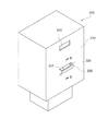
第1実施形態について、図1乃至3を参照しながら説明する。本実施形態に係る車両用空調装置10は、車両(全体は不図示)に搭載される空調装置であって、車室内の空調を行うための装置である。図1に示されるように、車両用空調装置10は、空調ユニット100と、粒子検知部200と、を備えている。
The first embodiment will be described with reference to FIGS. 1 to 3. The
先ず、空調ユニット100の構成について説明する。空調ユニット100は車両用空調装置10の主要部分であって、外部から取り込んだ空気の空調を行い、空調された空気を車室内に供給するものである。空調ユニット100は、ブロア収納部101と、ブロア130と、接続部140と、空調部150と、を備えている。
First, the configuration of the
ブロア収納部101は、車両用空調装置10のうち外部からの空気を取り込む部分となっている。ブロア収納部101の内部には、後述のブロア130が収容されている。ブロア収納部101には、内気入口111と外気入口112とが形成されている。内気入口111は、車室内から導入される空気の入口として形成された開口である。車室内の空間と内気入口111との間は、不図示のダクトによって接続されている。外気入口112は、車両の外から導入される空気の入口として形成された開口である。車両の外の空間と外気入口112との間も、不図示のダクトによって接続されている。
The
ブロア収納部101のうち、内気入口111と外気入口112との間には、不図示の内外気切り換えドアが設けられている。内外気切り換えドアの動作によって、内気入口111から流入する空気と、外気入口112から流入する空気と、の比率が調整される。尚、このような内外気切り換えドアの構成としては公知のものを採用し得るので、その具体的な図示や説明については省略する。
Of the
ブロア収納部101のうち、空気の流れ方向に沿ってブロア130よりも上流側(図1では上方側)となる位置には、粒子フィルタ120が配置されている。粒子フィルタ120は、内気入口111や外気入口112から流入した空気から、粒子を除去するためのフィルタである。空気が粒子フィルタ120を通ることにより、粒子濃度の低減された清浄な空気が車室内に吹き出される。
The
ブロア130は、車室内に吹き出されるように空気を送り出す送風装置である。ブロア130が駆動されると、内気入口111や外気入口112からブロア収納部101の内部に空気が引き込まれる。当該空気は、次に述べる接続部140及び空調部150を通って車室内に吹き出される。
The
接続部140は、ブロア収納部101と空調部150との間を繋ぐ流路として設けられた部分である。本実施形態では、ブロア収納部101と接続部140とが一体に形成されている。
The
空調部150は、空気の温度調節を行う部分である。空調部150の内部には、空気の除湿及び冷却を行うエバポレータ、空気の加熱を行うヒータコア、エバポレータ及びヒータコアのそれぞれを流れる空気の量を調整するエアミックスドア、等が配置されている。
The
空調部150のうち空気の流れ方向に沿って下流側となる部分には、デフロスタ吹き出し部151、フェイス吹き出し部152、及びフット吹き出し部153がそれぞれ設けられている。デフロスタ吹き出し部151は、車両の窓に向けて空調風を吹き出す部分である。フェイス吹き出し部152は、車両の乗員の顔に向けて空調風を吹き出す部分である。フット吹き出し部153は、車両の乗員の足元に向けて空調風を吹き出す部分である。デフロスタ吹き出し部151、フェイス吹き出し部152、及びフット吹き出し部153のそれぞれには不図示のドアが設けられており、ドアの開度によってそれぞれの吹き出し部から吹き出される空気の流量が調整される。尚、以上に説明したような空調部150の構造としては公知のものを採用し得るので、その具体的な図示や説明については省略する。
A
図1に示されるように、ブロア収納部101のうち粒子フィルタ120の端部近傍となる位置には、空気導入室160が形成されている。空気導入室160は、空調ユニット100の外側から、空調ユニット100の内部(具体的にはブロア収納部101の内部)に導入される空気が流れる空間、として形成されている。
As shown in FIG. 1, an
空気導入室160のうち空気の入口となる開口161は、粒子フィルタ120や後述の粒子検知部200よりも上方側となる位置に形成されている。開口161は、空調ユニット100の周囲の空間と、空気導入室160との間を連通させるものである。空気導入室160のうち空気の出口となる開口162は、粒子フィルタ120よりも僅かに下方側となる位置に形成されている。開口162は、空気導入室160と、ブロア収納部101のうち粒子フィルタ120よりも下方側の空間との間を連通させるものである。尚、上記のような開口161や開口162の位置はあくまで一例である。開口161や開口162は、それぞれ上記とは異なる位置に形成されていてもよい。
The
ブロア130が駆動されているときには、ブロア130の吸引力により、空気導入室160の空気は開口162を通ってブロア130側に排出される。これを補うように、外部の空気は開口161を通って空気導入室160に流入する。このため、本実施形態における空気導入室160の内部では、第1開口220よりも上方側となる位置(開口161)から下方側に向けて空気が流れることとなる。
When the
ブロア収納部101は、車両のうちインストルメントパネルの内側に配置されている。インストルメントパネルの内側の空間、すなわち、空気導入室160の外側の空間は、車室内と繋がっている。このため、開口161から空気導入室160に流入する空気は、車室内の空気となっている。
The
図1に示されるように、空調ユニット100のうち空気導入室160が形成されている部分は、粒子検知部200が取り付けられる部分となっている。粒子検知部200は、空気導入室160のうち側方の部分を区画するように、ブロア収納部101に対して外側から取り付けられている。粒子検知部200の上端の位置は、開口161よりも低い位置となっている。
As shown in FIG. 1, the portion of the
粒子検知部200は、空気中における粒子の濃度を測定するためのセンサユニットである。粒子検知部200は、図2に示されるケース210の内側に、不図示の発光部と受光部とを有している。発光部から発せられた光の一部は、粒子検知部200の内部に導入された空気中の粒子によって散乱され、更にその一部が受光部によって検知される。粒子検知部200は、受光部によって検知された光の光量に基づいて、空気中における粒子の有無や濃度を検知するように構成されている。尚、粒子検知部200が有する発光部や受光部の構成としては公知のものを採用し得るので、その図示や具体的な説明については省略する。
The
ケース210は、上記の発光部や受光部等を内部に収容する容器であって、略直方体状に形成されている。ケース210のうちブロア収納部101に対して取り付けられる面(つまり空気導入室160を区画する面)には、第1開口220と第2開口240とがそれぞれ形成されている。
The
第1開口220は、空気導入室160からの空気が流入するように形成された開口である。粒子検知部200は、第1開口220を通ってケース210の内側へと流入した空気中における粒子の濃度を測定する。当該空気は、既に述べたように車室内の空気である。
The
図2に示されるように、ケース210のうち第1開口220の周囲には流入ガイド部230が設けられている。流入ガイド部230は、第1開口220の縁から空気導入室160側に向けて突出しており、その上端には開口231が形成されている。開口231の縁は概ね水平面に沿っている。
As shown in FIG. 2, an
既に述べたように、空気導入室160では、上方側から下方側に向かう空気の流れが生じている。このため、当該空気の一部は、動圧によって開口231の内側に押し込められて、第1開口220からケース210の内側へと流入することとなる。当該空気は、粒子検知部200によってその粒子濃度が測定された後、第2開口240から空気導入室160へと排出される。このような流入ガイド部230は、空気導入室160を流れる空気の一部を第1開口220に導くように、ケース210に形成されたものということができる。
As already described, in the
第2開口240は、上記のように、空気導入室160へと空気を排出するために形成された開口である。本実施形態における第2開口240は、第1開口220よりも上方側となる位置に形成されている。
The
ところで、粒子検知部200による粒子濃度の測定が正確に行われるためには、第1開口220を通らない経路でケース210の内側に流入する空気の量を、可能な限り小さくする必要がある。「第1開口220を通らない経路」としては、例えば、ケース210を構成する複数の部品間における隙間を通るような経路が挙げられる。このような経路の幅は比較的狭いので、当該経路を空気が通る際に、空気に含まれる粒子の一部がフィルタリングされてしまうことがある。つまり、第1開口220を通らない経路でケース210の内側に流入した空気は、車室内の空気に比べて粒子濃度の小さい空気となっている。このため、第1開口220を通らない経路で流入する空気の量が大きくなると、粒子濃度の測定値が低い方にずれてしまうこととなってしまう。
By the way, in order for the
図3に示されるように、ケース210は、内壁212と外壁211とからなる2重構造となっている。本実施形態ではケース210を2重構造とすることにより、第1開口220を通らない経路でケース210の内側に流入する空気の量を低減している。ただし、内壁212と外壁211との間の空間にある空気は、上記のように隙間を通った空気であり、粒子濃度が低減された空気となっている。このような空気が第1開口220の部分から内側へと流入してしまうと、やはり正確な粒子濃度の測定ができなくなる。
As shown in FIG. 3, the
そこで、本実施形態では、第1開口220の近傍に遮断壁213、214、215、216を形成することで、内壁212と外壁211との間の空気が、第1開口220から内側に流入してしまうことを防止している。
Therefore, in the present embodiment, by forming the blocking
遮断壁213は、第1開口220の下端部となる位置において、外壁211から内壁212に向かって突出するように形成された壁である。遮断壁214は、第1開口220の下端部となる位置において、内壁212から外壁211に向かって突出するように形成された壁である。遮断壁213と遮断壁214とは上下に並ぶように配置されており、両者の間の隙間は小さくなっている。このような遮断壁213及び遮断壁214は、内壁212と外壁211との間の空間と、第1開口220との間を遮断するためのラビリンス構造として機能する。
The blocking
遮断壁215は、第1開口220の上端部となる位置において、外壁211から内壁212に向かって突出するように形成された壁である。遮断壁216は、第1開口220の上端部となる位置において、内壁212から外壁211に向かって突出するように形成された壁である。遮断壁215と遮断壁216とは上下に並ぶように配置されており、両者の間の隙間は小さくなっている。このような遮断壁215及び遮断壁215も、内壁212と外壁211との間の空間と、第1開口220との間を遮断するためのラビリンス構造として機能する。
The blocking
遮断壁213、214、215、216からなるラビリンス構造によって、内壁212と外壁211との間にある空気が、第1開口220を通ってケース210の内側に流入することが抑制されている。その結果、ケース210の内部に流入する空気のうち、第1開口220を通ってケース210の内部に流入する空気の占める割合が向上するので、粒子検知部200による測定精度の低下が抑制される。
The labyrinth structure including the
このように、遮断壁213、214、215、216は、第1開口220を通らない経路でケース210の内部に空気が流入することを抑制し、粒子検知部200による測定の精度を向上させる部分となっている。このような遮断壁213、214、215、216(ラビリンス構造)は、本実施形態における「精度向上部」に該当する。
In this way, the
本実施形態では、先に説明した流入ガイド部230が設けられていることにより、より多くの空気が第1開口220を通ってケース210の内側に流入することとなる。つまり、流入ガイド部230が設けられていることによっても、第1開口220を通ってケース210の内部に流入する空気の占める割合が向上している。従って、流入ガイド部230も、本実施形態における「精度向上部」の一つとして機能するものとなっている。
In the present embodiment, since the
第2実施形態について、図4を参照しながら説明する。以下では、第1実施形態と異なる点について主に説明し、第1実施形態と共通する点については適宜説明を省略する。 The second embodiment will be described with reference to FIG. In the following, the points different from the first embodiment will be mainly described, and the points common to the first embodiment will be omitted as appropriate.
本実施形態では、空気導入室160の上方側を区画する天壁171が、ケース210の上面201と対向する位置まで伸びるように形成されている。その結果、ケース210の第1開口220や流入ガイド部230は、天壁171によって上方から覆われた状態となっている。
In the present embodiment, the
また、ケース210の上面201には突出壁172が設けられている。突出壁172は、上方の天壁171に向かって突出するように形成されている。ただし、天壁171と突出壁172との間には隙間が形成されている。このように形成された突出壁172の位置は、天壁171に沿って第1開口220に向かう空気が流れる流路、の途中の位置ということができる。
Further, a protruding
天壁171及び突出壁172が設けられていることの効果について説明する。粒子検知部200では、粒子径が概ね2.5μm以下の、所謂「PM2.5」と称される粒子を検知対象としている。このため、第1開口220から流入する空気中に、上記よりも粒子径の大きな粒子(つまり測定対象外の粒子)が含まれている場合には、粒子検知部200による粒子濃度の測定精度が低下してしまうこととなる。具体的には、粒子検知部200で測定される粒子濃度が、実際の粒子濃度よりも高くなってしまう。
The effect of providing the
ただし、粒子径の大きな粒子は重力の影響をより受けやすいので、空気中において下方側に向かって移動(落下)しやすい。本実施形態では、第1開口220や流入ガイド部230の全体が、天壁171によって上方から覆われている。このため、ケース210の上方から落下してくる大径の粒子は、天壁171によって遮られるので、第1開口220に直接は流入しにくくなっている。
However, since particles having a large particle diameter are more susceptible to the influence of gravity, they are likely to move (fall) downward in the air. In the present embodiment, the entire
また、天壁171と上面201との間を開口161に向かって流れる空気は、突出壁172によりその流れ方向を上方側に変化させた後、再び開口161に向かって流れることとなる。このため、当該空気に大径の粒子が含まれていたとしても、当該粒子は突出壁172を乗り越えることができないので、開口161に到達しにくくなっている。
Further, the air flowing toward the
以上のように、本実施形態では、測定対象の粒子よりも大きい粒子がケース210の内部に流入することが、天壁171及び突出壁172のそれぞれによって抑制されている。その結果、大径の粒子による測定精度の低下が抑制されている。このような天壁171及び突出壁172は、本実施形態における「精度向上部」に該当する。
As described above, in the present embodiment, the inflow of particles larger than the particles to be measured into the
また、本実施形態では、大径の粒子がケース210の内側に堆積しにくくなるので、粒子検知部200のメンテナンス(掃除)の頻度を低下させるという効果も得られる。尚、上記のようにPM2.5を検知対象とするのはあくまで一例である。粒子検知部200による粒子濃度の測定は、PM2.5以外の粒子を検知対象として行われてもよい。
Further, in the present embodiment, since the large-diameter particles are less likely to be deposited inside the
第3実施形態について、図5を参照しながら説明する。以下では、上記の第2実施形態(図4)と異なる点について主に説明し、第2実施形態と共通する点については適宜説明を省略する。 The third embodiment will be described with reference to FIG. In the following, the points different from the second embodiment (FIG. 4) will be mainly described, and the points common to the second embodiment will be omitted as appropriate.
本実施形態では、空気導入室160の開口161が、図5における左側(つまりケース210側)に向けて開口するように形成されているのではなく、図5における紙面奥側及び手前側(不図示)に向けて開口するように形成されている。本実施形態でも、空気導入室160の外側において落下する大径の粒子は、天壁171によって遮られるので、第1開口220に直接は流入しにくくなっている。このような態様でも、第2実施形態で説明したものと同様の効果を奏する。
In the present embodiment, the
第4実施形態について、図6を参照しながら説明する。以下では、第2実施形態と異なる点について主に説明し、第2実施形態と共通する点については適宜説明を省略する。 The fourth embodiment will be described with reference to FIG. In the following, the points different from the second embodiment will be mainly described, and the points common to the second embodiment will be omitted as appropriate.
本実施形態では、ケース210の全体が、空気導入室160の方に向けて傾斜した状態で取り付けられている。その結果、ケース210のうち第1開口220が形成されている面202も、空気導入室160の方に向けて傾斜した状態となっている。
In the present embodiment, the
図6に示される点線DL1は、面202の上端から鉛直下方に向けて伸びるように描かれた線である。流入ガイド部230は、その全体が、点線DL1よりも面202側の範囲に配置されている。
The dotted line DL1 shown in FIG. 6 is a line drawn so as to extend vertically downward from the upper end of the
その結果、ケース210(面202)のうち第1開口220よりも上方側の部分は、第1開口220や流入ガイド部230を上方から覆う状態となっている。このため、空気導入室160の外側において落下する大径の粒子は、上記のように傾斜した面202によって遮られるので、第1開口220に直接は流入しにくくなっている。その結果、大径の粒子による測定精度の低下が抑制される。このように、ケース210(面202)のうち第1開口220よりも上方側の部分は、本実施形態における「精度向上部」に該当する。
As a result, the portion of the case 210 (surface 202) above the
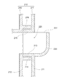
第5実施形態について、図7を参照しながら説明する。以下では、第2実施形態と異なる点について主に説明し、第2実施形態と共通する点については適宜説明を省略する。 A fifth embodiment will be described with reference to FIG. In the following, the points different from the second embodiment will be mainly described, and the points common to the second embodiment will be omitted as appropriate.
本実施形態では、空気導入室160における空気の入口である開口161が、空気導入室160の下端となる位置に形成されている。このため、空気導入室160のうちケース210の近傍においては、空気は下方側から上方側に向かって流れる。当該空気の一部が第1開口220からケース210の内側に流入するように、本実施形態における流入ガイド部230は、開口231を下方側に向けた状態で形成されている。
In the present embodiment, the
このような構成においては、測定対象外である大径の粒子が、開口161から第1開口220に到達することはより困難になっている。その結果、大径の粒子による測定精度の低下が抑制されている。
In such a configuration, it is more difficult for large-diameter particles that are not to be measured to reach the
ところで、本実施形態では、開口161と開口162のいずれもが空気導入室160の下端部近傍に形成されている。このため、図7において矢印AR3で示されるように、開口161から流入した空気が、第1開口220に向かうことなく開口162から排出されてしまう可能性がある。
By the way, in the present embodiment, both the
そこで、本実施形態では、上記のような経路で空気が流れることを防止するために、空気導入室160の内側に案内壁173が設けられている。案内壁173は、開口161のうちケース210とは反対側(図7では右側)の縁の部分から、第1開口220よりも高い位置まで伸びるように形成された壁である。このような案内壁173により、開口161から空気導入室160に流入した空気は、第1開口220よりも高い位置まで導かれる。その結果、第1開口220の近傍における空気の流れが確保されるので、当該空気の一部が第1開口220の内側へと流入しやすくなっている。大径の粒子を含まない空気を第1開口220まで導く案内壁173は、本実施形態における「精度向上部」に該当する。このような態様でも、第2実施形態で説明したものと同様の効果を奏する。
Therefore, in the present embodiment, a
第1開口220を通らない経路でケース210の内部に空気が流入することを抑制するための精度向上部(例えば第1実施形態の流入ガイド部230等)と、測定対象の粒子よりも大きい粒子が第1開口220からケース210の内部に流入することを抑制するための精度向上部(例えば第2実施形態の天壁171等)とは、車両用空調装置10においていずれか一方のみが設けられていてもよく、両方が設けられていてもよい。
An accuracy improving unit (for example, an
以上、具体例を参照しつつ本実施形態について説明した。しかし、本開示はこれらの具体例に限定されるものではない。これら具体例に、当業者が適宜設計変更を加えたものも、本開示の特徴を備えている限り、本開示の範囲に包含される。前述した各具体例が備える各要素およびその配置、条件、形状などは、例示したものに限定されるわけではなく適宜変更することができる。前述した各具体例が備える各要素は、技術的な矛盾が生じない限り、適宜組み合わせを変えることができる。 The present embodiment has been described above with reference to specific examples. However, the present disclosure is not limited to these specific examples. Those skilled in the art with appropriate design changes to these specific examples are also included in the scope of the present disclosure as long as they have the features of the present disclosure. Each element included in each of the above-mentioned specific examples, its arrangement, conditions, shape, etc. is not limited to the illustrated one, and can be appropriately changed. The combinations of the elements included in each of the above-mentioned specific examples can be appropriately changed as long as there is no technical contradiction.
10:車両用空調装置
100:空調ユニット
160:空気導入室
171:天壁
172:突出壁
173:案内壁
200:粒子検知部
202:面
210:ケース
213,214,215,216:遮断壁
220:第1開口
230:流入ガイド部
240:第2開口
10: Vehicle air conditioner 100: Air conditioner unit 160: Air introduction chamber 171: Top wall 172: Protruding wall 173: Guide wall 200: Particle detector 202: Surface 210:
Claims (4)
空調された空気を車室内に供給する空調ユニット(100)と、
空気中における粒子の濃度を測定する粒子検知部(200)と、を備え、
前記空調ユニットのうち前記粒子検知部が取り付けられる部分には、前記空調ユニットの内側へと導入される空気が流れる空間、である空気導入室(160)が形成されており、
前記粒子検知部は、前記空気導入室からの空気が流入する第1開口(220)と、前記空気導入室へと空気が排出される第2開口(240)と、がそれぞれ形成されたケース(210)を有しており、前記第1開口から前記ケースの内部に流入した空気中における前記粒子の濃度を測定するように構成されたものであって、
前記第1開口を通らない経路で前記ケースの内部に空気が流入すること、及び、測定対象の粒子よりも大きい粒子が前記第1開口から前記ケースの内部に流入すること、のうち少なくとも一方を抑制することにより、前記粒子検知部による測定の精度を向上させる精度向上部を更に備えており、
前記精度向上部は、
前記ケースの内部に流入する空気のうち、前記第1開口を通って前記ケースの内部に流入する空気の占める割合を向上させるように構成されており、
前記ケースは、内壁(212)と外壁(211)とからなる2重構造となっており、
前記精度向上部は、
前記内壁と外壁との間にある空気が前記ケースの内部に流入することを抑制するよう、前記第1開口の近傍に形成されたラビリンス構造(213,214,215,216)である車両用空調装置。 A vehicle air conditioner (10)
An air-conditioning unit (100) that supplies air-conditioned air into the passenger compartment,
A particle detector (200) for measuring the concentration of particles in the air is provided.
An air introduction chamber (160), which is a space through which air introduced into the air conditioning unit flows, is formed in a portion of the air conditioning unit to which the particle detection unit is attached.
The particle detection unit has a case (220) in which a first opening (220) into which air from the air introduction chamber flows in and a second opening (240) in which air is discharged into the air introduction chamber are formed. 210), and is configured to measure the concentration of the particles in the air flowing into the inside of the case from the first opening.
At least one of the fact that air flows into the case through a path that does not pass through the first opening and that particles larger than the particles to be measured flow into the inside of the case through the first opening. By suppressing it, it is further provided with an accuracy improving unit for improving the accuracy of measurement by the particle detecting unit .
The accuracy improving unit
It is configured to improve the proportion of the air flowing into the inside of the case through the first opening of the air flowing into the case.
The case has a double structure consisting of an inner wall (212) and an outer wall (211).
The accuracy improving unit
Vehicle air conditioner having a labyrinth structure (213,214,215,216) formed in the vicinity of the first opening so as to prevent air between the inner wall and the outer wall from flowing into the case. apparatus.
空調された空気を車室内に供給する空調ユニット(100)と、
空気中における粒子の濃度を測定する粒子検知部(200)と、を備え、
前記空調ユニットのうち前記粒子検知部が取り付けられる部分には、前記空調ユニットの内側へと導入される空気が流れる空間、である空気導入室(160)が形成されており、
前記粒子検知部は、前記空気導入室からの空気が流入する第1開口(220)と、前記空気導入室へと空気が排出される第2開口(240)と、がそれぞれ形成されたケース(210)を有しており、前記第1開口から前記ケースの内部に流入した空気中における前記粒子の濃度を測定するように構成されたものであって、
前記第1開口を通らない経路で前記ケースの内部に空気が流入すること、及び、測定対象の粒子よりも大きい粒子が前記第1開口から前記ケースの内部に流入すること、のうち少なくとも一方を抑制することにより、前記粒子検知部による測定の精度を向上させる精度向上部を更に備えており、
前記精度向上部は、
測定対象の粒子よりも大きい粒子が前記第1開口から前記ケースの内部に流入すること、を抑制するように構成されており、
前記空気導入室は、前記第1開口よりも上方側となる位置から下方側に向けて空気が流れるように構成されており、
前記精度向上部は、前記第1開口を上方から覆うように設けられた天壁(171)を有する車両用空調装置。 A vehicle air conditioner (10)
An air-conditioning unit (100) that supplies air-conditioned air into the passenger compartment,
A particle detector (200) for measuring the concentration of particles in the air is provided.
An air introduction chamber (160), which is a space through which air introduced into the air conditioning unit flows, is formed in a portion of the air conditioning unit to which the particle detection unit is attached.
The particle detection unit has a case (220) in which a first opening (220) into which air from the air introduction chamber flows in and a second opening (240) in which air is discharged into the air introduction chamber are formed. 210), and is configured to measure the concentration of the particles in the air flowing into the inside of the case from the first opening.
At least one of the fact that air flows into the case through a path that does not pass through the first opening and that particles larger than the particles to be measured flow into the inside of the case through the first opening. It is further provided with an accuracy improving unit that improves the accuracy of measurement by the particle detecting unit by suppressing the particle detection unit.
The accuracy improving unit
It is configured to prevent particles larger than the particles to be measured from flowing into the case through the first opening.
The air introduction chamber is configured so that air flows downward from a position above the first opening.
The accuracy unit, car dual air conditioner that having a first opening disposed so as to cover from above the top wall (171).
空調された空気を車室内に供給する空調ユニット(100)と、
空気中における粒子の濃度を測定する粒子検知部(200)と、を備え、
前記空調ユニットのうち前記粒子検知部が取り付けられる部分には、前記空調ユニットの内側へと導入される空気が流れる空間、である空気導入室(160)が形成されており、
前記粒子検知部は、前記空気導入室からの空気が流入する第1開口(220)と、前記空気導入室へと空気が排出される第2開口(240)と、がそれぞれ形成されたケース(210)を有しており、前記第1開口から前記ケースの内部に流入した空気中における前記粒子の濃度を測定するように構成されたものであって、
前記第1開口を通らない経路で前記ケースの内部に空気が流入すること、及び、測定対象の粒子よりも大きい粒子が前記第1開口から前記ケースの内部に流入すること、のうち少なくとも一方を抑制することにより、前記粒子検知部による測定の精度を向上させる精度向上部を更に備えており、
前記精度向上部は、
測定対象の粒子よりも大きい粒子が前記第1開口から前記ケースの内部に流入すること、を抑制するように構成されており、
前記空気導入室は、前記第1開口よりも下方側となる位置から上方側に向けて空気が流れるように構成されており、
前記精度向上部は、前記空気導入室に流入した空気を、前記第1開口よりも高い位置まで導くように設けられた案内壁(173)を有する車両用空調装置。 A vehicle air conditioner (10)
An air-conditioning unit (100) that supplies air-conditioned air into the passenger compartment,
A particle detector (200) for measuring the concentration of particles in the air is provided.
An air introduction chamber (160), which is a space through which air introduced into the air conditioning unit flows, is formed in a portion of the air conditioning unit to which the particle detection unit is attached.
The particle detection unit has a case (220) in which a first opening (220) into which air from the air introduction chamber flows in and a second opening (240) in which air is discharged into the air introduction chamber are formed. 210), and is configured to measure the concentration of the particles in the air flowing into the inside of the case from the first opening.
At least one of the fact that air flows into the case through a path that does not pass through the first opening and that particles larger than the particles to be measured flow into the inside of the case through the first opening. It is further provided with an accuracy improving unit that improves the accuracy of measurement by the particle detecting unit by suppressing the particle detection unit.
The accuracy improving unit
It is configured to prevent particles larger than the particles to be measured from flowing into the case through the first opening.
The air introduction chamber is configured so that air flows from a position below the first opening toward an upward side.
The accuracy unit, the inflow air in the air intake chamber, the car dual air conditioner that having a guide wall (173) provided to guide up to a position higher than the first opening.
Priority Applications (4)
| Application Number | Priority Date | Filing Date | Title |
|---|---|---|---|
| JP2017146619A JP6791049B2 (en) | 2017-07-28 | 2017-07-28 | Vehicle air conditioner |
| PCT/JP2018/023012 WO2019021682A1 (en) | 2017-07-28 | 2018-06-15 | Vehicular air conditioner |
| DE112018003844.0T DE112018003844T5 (en) | 2017-07-28 | 2018-06-15 | Air conditioning device for a vehicle |
| CN201880041810.8A CN110785305B (en) | 2017-07-28 | 2018-06-15 | Air conditioner for vehicle |
Applications Claiming Priority (1)
| Application Number | Priority Date | Filing Date | Title |
|---|---|---|---|
| JP2017146619A JP6791049B2 (en) | 2017-07-28 | 2017-07-28 | Vehicle air conditioner |
Publications (3)
| Publication Number | Publication Date |
|---|---|
| JP2019026039A JP2019026039A (en) | 2019-02-21 |
| JP2019026039A5 JP2019026039A5 (en) | 2019-10-31 |
| JP6791049B2 true JP6791049B2 (en) | 2020-11-25 |
Family
ID=65040131
Family Applications (1)
| Application Number | Title | Priority Date | Filing Date |
|---|---|---|---|
| JP2017146619A Active JP6791049B2 (en) | 2017-07-28 | 2017-07-28 | Vehicle air conditioner |
Country Status (4)
| Country | Link |
|---|---|
| JP (1) | JP6791049B2 (en) |
| CN (1) | CN110785305B (en) |
| DE (1) | DE112018003844T5 (en) |
| WO (1) | WO2019021682A1 (en) |
Families Citing this family (1)
| Publication number | Priority date | Publication date | Assignee | Title |
|---|---|---|---|---|
| WO2022176727A1 (en) * | 2021-02-16 | 2022-08-25 | 株式会社ヴァレオジャパン | Vehicular air conditioning device |
Family Cites Families (10)
| Publication number | Priority date | Publication date | Assignee | Title |
|---|---|---|---|---|
| JP3176056B2 (en) * | 1990-09-25 | 2001-06-11 | 松下電工株式会社 | Air purifier |
| JPH0472009U (en) * | 1990-11-07 | 1992-06-25 | ||
| JP3617144B2 (en) * | 1995-10-11 | 2005-02-02 | 株式会社デンソー | Air conditioner for vehicles |
| JPH11321289A (en) * | 1998-05-08 | 1999-11-24 | Zexel:Kk | Air conditioning system for motor vehicle |
| JP2000043549A (en) * | 1998-07-28 | 2000-02-15 | Calsonic Corp | Gas detecting device for vehicle |
| JP2002130195A (en) * | 2000-10-30 | 2002-05-09 | Denso Corp | Muffler |
| JP4533557B2 (en) * | 2001-05-25 | 2010-09-01 | 三菱重工業株式会社 | Gas detector and air conditioner using the same |
| JP2006151185A (en) * | 2004-11-29 | 2006-06-15 | Denso Corp | Air-conditioner for vehicle |
| DE102013214071A1 (en) * | 2013-07-19 | 2015-01-22 | Bayerische Motoren Werke Aktiengesellschaft | Method for controlling a ventilation / air conditioning system of a vehicle and vehicle with such a ventilation / air conditioning system |
| WO2017043263A1 (en) * | 2015-09-09 | 2017-03-16 | 株式会社村田製作所 | Gas concentration detection device |
-
2017
- 2017-07-28 JP JP2017146619A patent/JP6791049B2/en active Active
-
2018
- 2018-06-15 WO PCT/JP2018/023012 patent/WO2019021682A1/en active Application Filing
- 2018-06-15 DE DE112018003844.0T patent/DE112018003844T5/en not_active Withdrawn
- 2018-06-15 CN CN201880041810.8A patent/CN110785305B/en active Active
Also Published As
| Publication number | Publication date |
|---|---|
| DE112018003844T5 (en) | 2020-04-09 |
| CN110785305A (en) | 2020-02-11 |
| JP2019026039A (en) | 2019-02-21 |
| CN110785305B (en) | 2022-12-30 |
| WO2019021682A1 (en) | 2019-01-31 |
Similar Documents
| Publication | Publication Date | Title |
|---|---|---|
| US20180195946A1 (en) | Dust sensor having flow rate control function | |
| US20120145010A1 (en) | Air cleaner | |
| JP2007168707A (en) | Air-conditioning system for vehicle | |
| JP6791049B2 (en) | Vehicle air conditioner | |
| CN113498386B (en) | Particle concentration detection device | |
| JP2005061819A (en) | Air conditioner and method for operating the air conditioner | |
| JP6920901B2 (en) | Air conditioner | |
| KR101755712B1 (en) | Apparatus for measuring concentration of co2 for vehicle | |
| WO2020090503A1 (en) | Pm sensor | |
| JP2020138615A5 (en) | ||
| KR101827165B1 (en) | Room air pollution decrease system of vehicle | |
| JP7234619B2 (en) | vehicle air conditioner | |
| WO2013098878A1 (en) | Air conditioning system, and railroad train provided with same | |
| JP2014016072A (en) | Air cleaner | |
| KR102342569B1 (en) | Air conditioner | |
| JP2019026039A5 (en) | ||
| WO2020149065A1 (en) | Pm sensor | |
| JP7017136B2 (en) | Vehicle dust measuring device | |
| JP2023122176A (en) | Air conditioner for vehicle | |
| WO2022176727A1 (en) | Vehicular air conditioning device | |
| JP5808986B2 (en) | Air blowing device | |
| JP6071375B2 (en) | Air conditioner for vehicles | |
| JP2013006464A (en) | Vehicular air conditioning device | |
| KR20210099945A (en) | Dust sensor | |
| JP2023033663A (en) | air conditioner |
Legal Events
| Date | Code | Title | Description |
|---|---|---|---|
| A521 | Request for written amendment filed |
Free format text: JAPANESE INTERMEDIATE CODE: A523 Effective date: 20190918 |
|
| A621 | Written request for application examination |
Free format text: JAPANESE INTERMEDIATE CODE: A621 Effective date: 20190918 |
|
| TRDD | Decision of grant or rejection written | ||
| A01 | Written decision to grant a patent or to grant a registration (utility model) |
Free format text: JAPANESE INTERMEDIATE CODE: A01 Effective date: 20201006 |
|
| A61 | First payment of annual fees (during grant procedure) |
Free format text: JAPANESE INTERMEDIATE CODE: A61 Effective date: 20201019 |
|
| R151 | Written notification of patent or utility model registration |
Ref document number: 6791049 Country of ref document: JP Free format text: JAPANESE INTERMEDIATE CODE: R151 |
|
| R250 | Receipt of annual fees |
Free format text: JAPANESE INTERMEDIATE CODE: R250 |