WO2020129148A1 - 浮体設備 - Google Patents
浮体設備 Download PDFInfo
- Publication number
- WO2020129148A1 WO2020129148A1 PCT/JP2018/046498 JP2018046498W WO2020129148A1 WO 2020129148 A1 WO2020129148 A1 WO 2020129148A1 JP 2018046498 W JP2018046498 W JP 2018046498W WO 2020129148 A1 WO2020129148 A1 WO 2020129148A1
- Authority
- WO
- WIPO (PCT)
- Prior art keywords
- tank
- natural gas
- plant
- liquefied natural
- pipe
- Prior art date
- Legal status (The legal status is an assumption and is not a legal conclusion. Google has not performed a legal analysis and makes no representation as to the accuracy of the status listed.)
- Ceased
Links
Images



Classifications
-
- B—PERFORMING OPERATIONS; TRANSPORTING
- B63—SHIPS OR OTHER WATERBORNE VESSELS; RELATED EQUIPMENT
- B63B—SHIPS OR OTHER WATERBORNE VESSELS; EQUIPMENT FOR SHIPPING
- B63B35/00—Vessels or similar floating structures specially adapted for specific purposes and not otherwise provided for
- B63B35/44—Floating buildings, stores, drilling platforms, or workshops, e.g. carrying water-oil separating devices
-
- B—PERFORMING OPERATIONS; TRANSPORTING
- B63—SHIPS OR OTHER WATERBORNE VESSELS; RELATED EQUIPMENT
- B63B—SHIPS OR OTHER WATERBORNE VESSELS; EQUIPMENT FOR SHIPPING
- B63B25/00—Load-accommodating arrangements, e.g. stowing, trimming; Vessels characterised thereby
- B63B25/02—Load-accommodating arrangements, e.g. stowing, trimming; Vessels characterised thereby for bulk goods
- B63B25/08—Load-accommodating arrangements, e.g. stowing, trimming; Vessels characterised thereby for bulk goods fluid
- B63B25/12—Load-accommodating arrangements, e.g. stowing, trimming; Vessels characterised thereby for bulk goods fluid closed
- B63B25/16—Load-accommodating arrangements, e.g. stowing, trimming; Vessels characterised thereby for bulk goods fluid closed heat-insulated
-
- B—PERFORMING OPERATIONS; TRANSPORTING
- B63—SHIPS OR OTHER WATERBORNE VESSELS; RELATED EQUIPMENT
- B63B—SHIPS OR OTHER WATERBORNE VESSELS; EQUIPMENT FOR SHIPPING
- B63B35/00—Vessels or similar floating structures specially adapted for specific purposes and not otherwise provided for
- B63B35/44—Floating buildings, stores, drilling platforms, or workshops, e.g. carrying water-oil separating devices
- B63B2035/448—Floating hydrocarbon production vessels, e.g. Floating Production Storage and Offloading vessels [FPSO]
Definitions
- the present invention relates to a floating facility equipped with a liquefied natural gas plant.
- NG natural gas
- a floating body such as a hull is placed on the ocean, and a plant for liquefying NG on the floating body (liquefied natural gas plant,
- FLNG floating LNG
- LNG plant Floating LNG
- FLNG is a huge structure with a total length of several hundred meters and built over a period of one year or more.
- an LNG plant configured by combining a large number of devices is arranged on the floating body portion, while a plurality of LNG tanks are provided in the floating body portion.
- one of the points to shorten the FLNG construction period is to make the timing at which it becomes possible to install the LNG plant on the floating body part as soon as possible after the LNG tank is built in the floating body part.
- Patent Document 1 describes a technology in which a tank area for storing LNG and a factory area including a natural gas liquefaction plant are constructed as separate floating body structures, and then these floating body structures are connected in the longitudinal direction. Has been done.
- Patent Document 1 does not describe any configuration suitable for constructing a floating structure in which a natural gas liquefaction plant is arranged on a tank region.
- the present invention has been made under such a background, and provides a technique for efficiently constructing a floating facility equipped with a liquefied natural gas plant.
- Floating body equipment of the present invention is arranged on the sea, a floating body portion having a planar shape longer in the ship length direction than in the ship width direction, A liquefied natural gas plant provided on the floating body, A plurality of liquefied natural gas tanks formed in the floating body,
- the plurality of liquefied natural gas tanks include a single array portion arranged in a row along the ship length direction of the floating body portion; On the upper surface side of the floating body portion in which the liquefied natural gas tank that constitutes the single array portion is formed, a tank dome, which is a drawing-out position where the pipes connected to each liquefied natural gas tank are drawn out from the upper surface side, is arranged along the ship length direction.
- Equipment constituting the liquefied natural gas plant in the plant arrangement region provided separately from the region where the tank dome is arranged, that is provided along the ship length direction, On the upper side of the array of the tank domes, a group of plant pipes in which a fluid handled in the liquefied natural gas plant flows, a group of tank pipes in which a fluid flowing in and out of the liquefied natural gas tank flows, and drawn out through the tank dome.
- a pipe support frame portion for stacking and holding a pipe and a connecting portion of the tank pipe group is provided along the ship length direction.
- the floating facility may have the following features.
- the present invention relates to a tank pipe group in which a fluid flowing in and out of a liquefied natural gas tank flows, and a pipe drawn out through a tank dome, above a tank dome that is finally installed in a process of constructing a liquefied natural gas tank in a floating body.
- a pipe support frame for stacking and holding the connecting portion between the tank pipe group and the tank pipe group is provided.
- FLNG FLNG
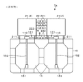
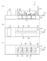
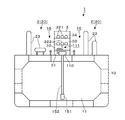
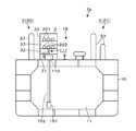
- a prior art example It is a cross-sectional view of FLNG according to a conventional example. It is a schematic diagram of FLNG which concerns on embodiment. It is a cross-sectional view of FLNG according to the embodiment. It is a cross-sectional view of FLNG according to the second embodiment. It is a transverse cross section of FLNG concerning a 3rd embodiment. It is a top view of FLNG concerning a 4th embodiment. It is a top view which shows the modification of FLNG which concerns on each embodiment. It is a schematic diagram which concerns on the variation of the method of installing a loading arm to a floating body part.
- a turret 12 that is a mooring facility is provided on the bow side of a hull 10 that is a floating body portion arranged on the ocean in the FLNG 1a.
- the turret 12 is connected to a mooring line for mooring the hull 10 and is also connected to a riser for underwater transportation of mined natural gas (NG) (a mooring line and a riser are not shown).
- NG mined natural gas
- a flare stack 14 for burning surplus gas generated in the LNG plant 2 the LNG tank 11, and the like is provided on the main body of the hull 10 at a position closer to the port side on the bow side, for example.
- a pipe rack 22 is provided so as to extend along the length direction of the hull 10 in the central region in the ship width direction.
- the pipe rack 22 is a frame structure that holds a plurality of plant pipes 221 (plant pipe group) through which various fluids handled in the LNG plant 2 flow.
- the areas adjacent to the left and right sides of the pipe rack 22 are the plant arrangement areas 20 in which the devices forming the LNG plant 2 are arranged (FIG. 1(c)).
- a plurality of modules 21 that configure the LNG plant 2 are provided side by side in the front-rear direction.
- the module 21 is a divisional unit in which a device group that constitutes a process unit that performs various processes for NG is incorporated in a common frame.
- static equipment such as tower tanks and heat exchangers, moving equipment such as pumps, connection pipes that connect between each static equipment and moving equipment, and between pipes on the pipe rack 22 side, A large number of devices forming the LNG plant 2 are arranged.
- modules 21 are arranged at positions on the upper side of a tank dome 110, which will be described later, via column bases 211 arranged on the deck of the hull 10.
- the module 21 may be configured by arranging these device groups on a pallet-shaped base.
- a gas-liquid separation unit that separates the liquid contained in the NG received from the riser
- a pretreatment unit that removes acidic gas (carbon dioxide, hydrogen sulfide, etc.), water, and mercury
- acidic gas carbon dioxide, hydrogen sulfide, etc.
- the housing portion 13 is provided at a position rearward of the area where the module 21 and the pipe rack 22 are provided.
- a plurality of LNG tanks 11 are formed in the main body of the hull 10.
- the LNG tank 11 is composed of a membrane type tank.
- the hull 10 is divided into a plurality of parts in the ship width direction to provide a plurality of LNG tanks 11. Further, by arranging a plurality of sets of these LNG tanks 11 arranged in the ship width direction, a row of the plurality of LNG tanks 11 is arranged when viewed along the ship length direction. As shown in FIG. 1(c), the FLNG 1a is provided with two rows including four LNG tanks 11.
- FIG. 2 is a vertical sectional front view of the FLNG 1a viewed from the position A-A′ in FIG. 1(c).
- a tank dome 110 is installed on the upper surface side of each LNG tank 11.
- the tank dome 110 is a drawing position where various pipes (loading pipes, offloading pipes, rundown pipes, vapor pipes, and the like) connected to the LNG tank 11 are drawn out to the upper surface side of the hull 10.
- the tank dome 110 is provided at a position penetrating the ceiling of the main body of the LNG tank 11, and is provided with, for example, a cylindrical or square dome main body to which these pipes are attached, an opening/closing valve for each pipe, and the like.
- FIG. 2 shows a state in which only one offloading pipe 152 for discharging LNG in each LNG tank 11 using the LNG pump 151 is connected to the tank dome 110.
- a large number of pipes are drawn out to the upper surface side of the hull 10 via the tank dome 110.
- the module 21 that constitutes the LNG plant 2 is supported on a high floor via a column base 211 provided on the deck of the hull 10 to avoid interference with the tank dome 110.
- the pipe drawn to the upper surface side of the hull 10 via the tank dome 110 is connected to various main pipes.
- the off-loading pipe 152 is connected to the off-loading main pipe that is connected to the loading arm 41 that discharges LNG toward the LNG transport ship 5.
- the rundown pipe is connected to a rundown main pipe that causes the LNG liquefied in the liquefaction unit of the LNG plant 2 to flow into each LNG tank 11.
- the pipes through which the fluid flowing in and out of the LNG tank 11, such as the offloading main pipe and the rundown main pipe are called tank pipes 222.
- the various pipes drawn out through the tank dome 110 and the tank pipe 222 are connected through a branch pipe.
- the tank dome 110 is provided with a large number of pipes, and these pipes are connected to the tank pipes 222, respectively.
- the circumference of the actual tank dome 110 is in a state in which a large number of branch pipes are intricately arranged so as not to interfere with each other.
- the area in which the branch pipe is arranged is referred to as a connecting portion 111.
- the tank pipe 222 which is connected to each pipe on the tank dome 110 side through the connecting portion 111, is arranged on the lower side of the pipe rack 22.
- a space between a lower region where the tank pipe 222 is arranged and an upper shelf where the plant pipe 221 is held is a passage 223 through which an occupant passes.
- the above-mentioned tank dome 110 is a device installed in the final process of construction. Further, after the tank dome 110 is installed, in the connecting section 111, complicated pipe installation work for connecting the tank pipe 222 and a large number of branch pipes is performed.
- the tank dome 110 is positioned below each module 21. The probability of doing so increases. For this reason, the installation work of the tank dome 110 and the connection part 111 becomes a waiting constraint. Therefore, by installing the module 21 on the hull 10, the construction period of the FLNG 1a was shortened.
- the LNG plant 2 is built by the stick built method described later, there is a restriction that the installation work cannot be started due to the restriction of the installation work.
- FIG. 4 is a vertical cross-sectional front view of FLNG1 from the position of BB′ in FIG. 3(c).
- the same components as those of the FLNG 1a described above are denoted by the same reference numerals as those used in FIG. The description is omitted.
- the FLNG 1 shown in FIGS. 3 and 4 is constructed by a so-called stick-built method in which plant equipment (component equipment of the LNG plant 2) 23 is individually arranged on the deck of the hull 10. A plant 2 is provided. Compared with the method of constructing the LNG plant 2 by the module 21, the stick built method can reduce the cost of the frame that constitutes the module 21.
- the plurality of LNG tanks 11 formed in the hull 10 are arranged in a row along the length direction of the hull 10 and arranged in a single array. Make up part.
- the tank width of each LNG tank 11 is set to a size within a range where the influence of sloshing does not occur.
- tank domes 110 of each hull 10 are provided side by side along the ship length direction, for example, in the central region in front of the hull in the ship width direction. By providing the tank dome 110 in each central region, LNG in the LNG tank 11 can be extracted evenly.
- a pipe support for stacking and holding the connecting portion 111, a plurality of tank pipes 222 (tank pipe group), and a plurality of plant pipes 221 (plant pipe group) on the upper side of the array of the tank dome 110.
- a frame part 3 is provided.
- the pipe support frame part 3 is an elongated shelf-like frame structure extending along the lengthwise direction of the hull 10, and has a tank dome stage 31, a connecting part stage 32, a tank pipe support stage 33 in order from the lower layer side.
- a plant pipe support stage 34 is provided.
- the installation region of the pipe support frame 3 (that is, A plant placement area 20 is provided separately from the area along which the plurality of tank domes 110 are arranged, along the ship length direction of the hull 10.
- plant equipment 23 that constitutes the LNG plant 2 is arranged in the plant arrangement area 20.
- the pipe support frame 3 of this example does not have the passage 223 provided in the pipe rack 22 of the conventional FLNG 1a. Therefore, the passage 16 may be installed between the pipe support frame 3 and the plant arrangement area 20.
- the passage 16 is installed so as to be used for at least one of a passage for passengers and a conveyance of the plant equipment 23 constituting the LNG plant 2.
- the FLNG1 of this example has the following effects.
- the pipe support frame 3 for stacking and holding the plant pipe 221, the tank pipe 222, and the joint 111 is provided ( FIG. 3(c), FIG. 4).
- the plant disposition region 20 By providing the plant disposition region 20 at a position separated from the pipe support frame 3, it is possible to start the construction of the LNG plant 2 without waiting for the completion of the tank dome 110, the joint 111, and the like.
- the pipe support frame 3 can be installed while stacking each stage in a timely manner according to the progress of the construction of the tank dome 110, the joint 111, and the LNG plant 2.
- the position where the pipe support frame 3 is provided is not limited to the central region of the hull 10 in the ship width direction.
- the pipe support frame 3 may be provided closer to the ship slip side than the central region as in FLNG 1b shown in FIG.
- the plant arranging region 20 is provided on the port side of the pipe support frame 3 toward the bow side, but the plant is arranged only on one side (for example, the starboard side) of the pipe support frame 3.
- the passage 16 is provided only between the plant supporting region 20 disposed on one side of the pipe supporting frame 3. Further, a path for transporting the plant equipment 23 may be provided between the piping support frame 3 and the plant arrangement area 20 arranged on the other side. Further, the passage 16 and the transportation passage for the plant equipment 23 may be used together.
- the LNG plant 2 provided in the plant placement area 20 is not limited to the one built by the stick built method.
- the module 21 may be arranged in the plant arrangement area 20 to construct the LNG plant 2.
- the module 21 may be of a type in which the devices of the LNG plant 2 are arranged in the frame, or may be of a type in which these devices are arranged on a pallet-shaped base.
- an arrangement portion other than the one-row arrangement may be included.
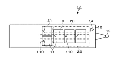
- the FLNG 1d shown in FIG. 7 has the LNG tanks 11 divided into a plurality of rows (two rows in this example) along the ship width direction of the hull 10 in addition to the single array portion in which the LNG tanks 11 are arranged in one row. Is included.
- FIG. 7 shows an example in which the module 21 is arranged at a position displaced from the tank dome 110 on the upper surface side of the LNG tanks 11 arranged in two rows.
- the installation area of the branch pipe extending from the installation position of the tank dome 110 to the tank pipe support step 33 of the pipe support frame 3 serves as the connecting portion 111.
- FIG. 3C an example is shown in which a plurality of tank domes 110 are arranged in a substantially straight line in the lower region (region where the tank domes 110 are arranged) of the pipe support frame 3. is there.
- FLNG1e in FIG. 8 when viewed along the ship width direction of the hull 10 for the purpose of avoiding the layout restrictions of the branch pipes in the connecting portion 111 and avoiding interference with other devices.
- These tank domes 110 may be arranged at positions displaced from each other. In this case as well, it can be said that a plurality of tank domes 110 are provided side by side in the region below the pipe support frame 3 along the ship length direction of the hull 10.
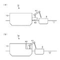
- FIG. 9 is a configuration example for preventing the loading arm 41 provided on the FLNG 1f, 1g side from becoming difficult to reach the LNG transport ship 5 as the hull becomes larger.
- the FLNG 1f shown in FIG. 9A shows an example in which an arm support base 42 protruding laterally from the hull 10 is provided, and the loading arm 41 is arranged on the arm support base 42.
- FLNG 1g shown in FIG. 9B shows an example in which the deck on the ship-sliding side of the hull is cut out to form a recess 43, and the loading arm 41 is disposed in the recess 43.
Landscapes
- Engineering & Computer Science (AREA)
- Chemical & Material Sciences (AREA)
- Combustion & Propulsion (AREA)
- Mechanical Engineering (AREA)
- Ocean & Marine Engineering (AREA)
- Architecture (AREA)
- Civil Engineering (AREA)
- Structural Engineering (AREA)
- Filling Or Discharging Of Gas Storage Vessels (AREA)
Abstract
【課題】液化天然ガスプラントを備えた浮体設備を効率的に建造する技術を提供する。 【解決手段】浮体設備1は、洋上に配置される浮体部10上に液化天然ガスプラント2が設けて構成され、その内部には船長方向に沿って複数の液化天然ガスタンク11が1列に配列された単配列部を含む。浮体部10の上面側には、各液化天然ガスタンクから配管が引き出される引き出し位置であるタンクドーム110が、船長方向に沿って並べて設けられ、前記タンクドーム110の並びの上方側に、プラント配管221群とタンク配管222群と取り合い部111とを積層保持する配管支持架構部3が、前記船長方向に沿って設けられている。
Description
本発明は、液化天然ガスプラントを備えた浮体設備に関する。
ガス田から産出された天然ガス(NG:Natural Gas)の液化処理を行う設備として、洋上に船体などの浮体部を配置し、当該浮体部上にNGの液化を行うプラント(液化天然ガスプラント、以下「LNGプラント」ともいう)を設けたFLNG(Floating LNG)と呼ばれる浮体設備が知られている。
FLNGは、全長が数百メートルにもなり、1年以上の期間をかけて建造される巨大な構造物である。特に浮体部上には、多数の機器を組み合わせて構成されるLNGプラントが配置される一方、当該浮体部内には複数のLNGタンクが設けられる。このため、浮体部内にLNGタンクを建造した後、浮体部上にLNGプラントを設置することが可能になるタイミングをできるだけ早めることが、FLNGの建造期間を短縮するポイントの一つとなる。
例えば特許文献1には、LNGを貯蔵するタンク領域と、天然ガス液化プラントを含む工場領域とを別個の浮体構造物として建造した後、これらの浮体構造物を長さ方向に繋ぎ合わせる技術が記載されている。
一方で特許文献1には、タンク領域上に天然ガス液化プラントが配置される浮体構造物を建造する場合に好適な構成については何ら記載されていない。
一方で特許文献1には、タンク領域上に天然ガス液化プラントが配置される浮体構造物を建造する場合に好適な構成については何ら記載されていない。
本発明は、このような背景の下になされたものであり、液化天然ガスプラントを備えた浮体設備を効率的に建造する技術を提供する。
本発明の浮体設備は、洋上に配置され、船幅方向よりも船長方向に長い平面形状を有する浮体部と、
前記浮体部上に設けられた液化天然ガスプラントと、
前記浮体部内に形成された複数の液化天然ガスタンクと、を備え、
前記複数の液化天然ガスタンクは、前記浮体部の船長方向に沿って1列に配列された単配列部を含むことと、
当該単配列部を構成する液化天然ガスタンクが形成された浮体部の上面側には、各液化天然ガスタンクに繋がる配管が当該上面側より引き出される引き出し位置であるタンクドームが、前記船長方向に沿って並べて設けられていることと、
前記液化天然ガスプラントを構成する機器は、前記タンクドームが並ぶ領域と分離して設けられたプラント配置領域に、前記船長方向に沿って設けられていることと、
前記タンクドームの並びの上方側に、前記液化天然ガスプラントで取り扱われる流体が流れるプラント配管群と、前記液化天然ガスタンクを流入出する流体が流れるタンク配管群と、前記タンクドームを介して引き出される配管と前記タンク配管群との取り合い部と、を積層保持する配管支持架構部が、前記船長方向に沿って設けられていることと、を特徴とする。
前記浮体部上に設けられた液化天然ガスプラントと、
前記浮体部内に形成された複数の液化天然ガスタンクと、を備え、
前記複数の液化天然ガスタンクは、前記浮体部の船長方向に沿って1列に配列された単配列部を含むことと、
当該単配列部を構成する液化天然ガスタンクが形成された浮体部の上面側には、各液化天然ガスタンクに繋がる配管が当該上面側より引き出される引き出し位置であるタンクドームが、前記船長方向に沿って並べて設けられていることと、
前記液化天然ガスプラントを構成する機器は、前記タンクドームが並ぶ領域と分離して設けられたプラント配置領域に、前記船長方向に沿って設けられていることと、
前記タンクドームの並びの上方側に、前記液化天然ガスプラントで取り扱われる流体が流れるプラント配管群と、前記液化天然ガスタンクを流入出する流体が流れるタンク配管群と、前記タンクドームを介して引き出される配管と前記タンク配管群との取り合い部と、を積層保持する配管支持架構部が、前記船長方向に沿って設けられていることと、を特徴とする。
前記浮体設備は以下の特徴を備えてもよい。
(a)前記プラント配置領域には、前記浮体部の甲板上に、前記液化天然ガスプラントの構成機器が個別に配置されていること。
(b)前記配管支持架構部と、前記プラント配置領域との間には、乗員の通行用の通路および/または前記液化天然ガスプラントを構成する機器の搬送用の通路が設けられていること。
(c)前記単配列部に含まれない複数の液化天然ガスタンクを備え、これらの液化天然ガスタンクは、前記船幅方向に沿って前記浮体部内を複数に区画して形成されていること。
(a)前記プラント配置領域には、前記浮体部の甲板上に、前記液化天然ガスプラントの構成機器が個別に配置されていること。
(b)前記配管支持架構部と、前記プラント配置領域との間には、乗員の通行用の通路および/または前記液化天然ガスプラントを構成する機器の搬送用の通路が設けられていること。
(c)前記単配列部に含まれない複数の液化天然ガスタンクを備え、これらの液化天然ガスタンクは、前記船幅方向に沿って前記浮体部内を複数に区画して形成されていること。
本発明は、浮体部に液化天然ガスタンクを建造する過程で最後に設置されるタンクドームの上方側に、液化天然ガスタンクを流入出する流体が流れるタンク配管群や、タンクドームを介して引き出される配管とタンク配管群との取り合い部などを積層保持する配管支持架構部を設ける。この配管支持架構部から分離された位置にプラント配置領域を設けることにより、タンクドームや取り合い部などの完成を待たずに液化天然ガスプラントの建造に着手できる。
初めに、図1を参照しながら従来のFLNG1aの構成を説明する。
FLNG1aにおいて洋上に配置される浮体部であるハル(Hull)10の船首側には、係留設備であるタレット12が設けられている。タレット12は、係留索に接続されてハル10の係留を行うと共に、採掘された天然ガス(NG)の水中輸送を行うライザーに接続されている(係留索やライザーは不図示)。以下、タレット12が設けられている向きをハル10の前方として説明を行う。
ハル10の本体上の例えば船首側左舷寄りの位置には、LNGプラント2やLNGタンク11などで発生した余剰なガスを燃焼するためのフレアスタック14が設けられている。
FLNG1aにおいて洋上に配置される浮体部であるハル(Hull)10の船首側には、係留設備であるタレット12が設けられている。タレット12は、係留索に接続されてハル10の係留を行うと共に、採掘された天然ガス(NG)の水中輸送を行うライザーに接続されている(係留索やライザーは不図示)。以下、タレット12が設けられている向きをハル10の前方として説明を行う。
ハル10の本体上の例えば船首側左舷寄りの位置には、LNGプラント2やLNGタンク11などで発生した余剰なガスを燃焼するためのフレアスタック14が設けられている。
図1(b)に示すように、ハル10を上面側から見たとき、船幅方向の中央領域には、ハル10の長さ方向に沿って伸びるようにパイプラック22が設けられている。パイプラック22は、LNGプラント2内で取り扱われる各種の流体が流れる複数のプラント配管221(プラント配管群)を保持する架構構造体である。
パイプラック22の左右両脇に隣接する領域は、LNGプラント2を構成する機器が配置されるプラント配置領域20となっている(図1(c))。これらのプラント配置領域20には、各々、LNGプラント2を構成する複数のモジュール21が前後方向に並べて設けられている。
例えばモジュール21は、共通の架構内に、NGに対する各種処理などを行うプロセス部を構成する機器群を組み込んだ区分単位である。各モジュール21内には、塔槽や熱交換器などの静機器、ポンプなどの動機器、各静機器と動機器の間や、パイプラック22側の配管との間を接続する接続配管など、LNGプラント2を構成する多数の機器が配置される。
例えばモジュール21は、共通の架構内に、NGに対する各種処理などを行うプロセス部を構成する機器群を組み込んだ区分単位である。各モジュール21内には、塔槽や熱交換器などの静機器、ポンプなどの動機器、各静機器と動機器の間や、パイプラック22側の配管との間を接続する接続配管など、LNGプラント2を構成する多数の機器が配置される。
これらのモジュール21は、ハル10の甲板上に配置された柱脚部211を介して、後述のタンクドーム110の上方側の位置に配置される。
なお、架構内に各種機器群を配置してモジュール21を構成することは必須の要件ではない。例えば、パレット状の基台の上にこれらの機器群を配置してモジュール21を構成してもよい。
なお、架構内に各種機器群を配置してモジュール21を構成することは必須の要件ではない。例えば、パレット状の基台の上にこれらの機器群を配置してモジュール21を構成してもよい。
LNGプラント2を構成するプロセス部としては、ライザーから受け入れたNGに含まれる液体を分離する気液分離部、酸性ガス(二酸化炭素や硫化水素など)や水分、水銀の除去を行う前処理部、不純物が除去されたNGの蒸留分離を行い、メタンを得る蒸留分離部、メタンの液化を行う液化部などを例示することができる。
さらにモジュール21やパイプラック22が設けられている領域よりも後方側の位置には、居住部13が設けられている。
さらにモジュール21やパイプラック22が設けられている領域よりも後方側の位置には、居住部13が設けられている。
また、図1(a)、(c)、図2に示すように、ハル10の本体内には、複数のLNGタンク11が形成されている。例えばLNGタンク11は、メンブレン方式のタンクにより構成されている。
このFLNG1aにおいては、スロッシングの発生を抑制し、またハル10内の空間を効率的に使用する観点から、ハル10を船幅方向に複数に分割して複数のLNGタンク11を設けている。さらに船幅方向に並ぶこれらのLNGタンク11の組を、複数組並べることにより、船長方向に沿って見たとき複数のLNGタンク11の列が配置されている。図1(c)に示すように、本FLNG1aは、4基のLNGタンク11を含む列が2列設けられている。
このFLNG1aにおいては、スロッシングの発生を抑制し、またハル10内の空間を効率的に使用する観点から、ハル10を船幅方向に複数に分割して複数のLNGタンク11を設けている。さらに船幅方向に並ぶこれらのLNGタンク11の組を、複数組並べることにより、船長方向に沿って見たとき複数のLNGタンク11の列が配置されている。図1(c)に示すように、本FLNG1aは、4基のLNGタンク11を含む列が2列設けられている。
図2は、図1(c)のA-A’の位置からFLNG1aを矢視した縦断正面図である。図2に示すように、各LNGタンク11の上面側には、タンクドーム110が設置されている。タンクドーム110は、LNGタンク11に繋がる各種配管(ローディング用配管、オフローディング用配管、ランダウン配管やベーパー配管など)が、ハル10の上面側へ引き出される引き出し位置である。例えばタンクドーム110は、LNGタンク11本体の天井部を貫通する位置に設けられ、これらの配管が取り付けられる、例えば円筒状または四角形状のドーム本体や、各配管の開閉バルブなどを備える。
図示の便宜上、図2にはLNGポンプ151を用いて各LNGタンク11内のLNGを払い出す1本のオフローディング用配管152のみがタンクドーム110に接続されている状態を示してある。実際には上述のように、タンクドーム110を介して多数の配管がハル10の上面側へと引き出されている。
なお、LNGプラント2を構成するモジュール21は、ハル10の甲板に設けられた柱脚部211を介して高床支持されることにより、タンクドーム110との干渉をさけている。
なお、LNGプラント2を構成するモジュール21は、ハル10の甲板に設けられた柱脚部211を介して高床支持されることにより、タンクドーム110との干渉をさけている。
タンクドーム110を介してハル10の上面側へ引き出された配管は、各種の本配管に接続される。例えばオフローディング用配管152は、LNG輸送船5へ向けてLNGを払い出すローディングアーム41へと繋がるオフローディング用本管に接続される。また、ランダウン用配管は、LNGプラント2の液化部にて液化されたLNGを各LNGタンク11へ流入させるランダウン用本管に接続される。以下、これらオフローディング用本管やランダウン用本管など、LNGタンク11を流入出する流体が流れる配管をタンク配管222と呼ぶ。
タンクドーム110を介して引き出された各種配管と、タンク配管222とは、枝配管を介して接続される。既述のように、タンクドーム110には多数の配管が設けられ、これらの配管が各々タンク配管222に接続される。このため、実際のタンクドーム110の周囲は、多数の枝配管が互いに干渉しないように入り組んで配置された状態となっている。当該枝配管の配置されている領域を取り合い部111と呼ぶ。
図2に示すように、取り合い部111を介してタンクドーム110側の各配管と接続されたタンク配管222は、パイプラック22の下部側に配置される。パイプラック22において、タンク配管222が配置されている下部側の領域と、プラント配管221が保持されている上部側の棚段との間の空間は、乗員が通行する通路223となっている。
以上に説明した概略構成を有する従来のFLNG1aを建造する際の問題点について説明する。
ハル10内に各LNGタンク11を建造するにあたって、既述のタンクドーム110は建造の最終工程にて設置される機器である。また、タンクドーム110が設置された後、取り合い部111にいては、タンク配管222と多数の枝配管とを接続する入り組んだ配管設置工事が行われる。
ハル10内に各LNGタンク11を建造するにあたって、既述のタンクドーム110は建造の最終工程にて設置される機器である。また、タンクドーム110が設置された後、取り合い部111にいては、タンク配管222と多数の枝配管とを接続する入り組んだ配管設置工事が行われる。
一方で、ハル10の船長方向に沿って複数のLNGタンク11の列が配置された従来のFLNG1aにおいては、図1(c)に示すように、各モジュール21の下方側にタンクドーム110が位置してしまう蓋然性が高くなる。このため、タンクドーム110や取り合い部111の設置工事が待ち制約となってしまうことから、ハル10上へモジュール21を設置することで、FLNG1aの建造工期を短縮していた。
一方、後述のスティックビルト方式にてLNGプラント2を建造する場合には、上記設置工事が制約となって大型のプラント機器23の設置を開始できないといった制約があった。
一方、後述のスティックビルト方式にてLNGプラント2を建造する場合には、上記設置工事が制約となって大型のプラント機器23の設置を開始できないといった制約があった。
上述の課題を解決するため、以下の実施形態に係るFLNG1は、タンクドーム110や取り合い部111の設置とLNGプラント2の建造とを独立して行うことができる構造となっている。以下、図3、図4を参照しながら当該FLNG1の構成について説明する。図4は、図3(c)のB-B’の位置からFLNG1を矢視した縦断正面図である。
なお以下図3~図9を参照しながら説明する各FLNG1、1b~1gにおいて、既述のFLNG1aと共通の構成要素には、図1にて用いたものと共通の符号を付し、再度の説明を省略する。
なお以下図3~図9を参照しながら説明する各FLNG1、1b~1gにおいて、既述のFLNG1aと共通の構成要素には、図1にて用いたものと共通の符号を付し、再度の説明を省略する。
はじめに、図3、図4に示すFLNG1には、ハル10の甲板上に、プラント機器(LNGプラント2の構成機器)23を個別に配置したいわゆるスティックビルト(stick-built)方式で建造されたLNGプラント2が設けられている。モジュール21によりLNGプラント2を建造する方式と比較して、スティックビルト方式は、モジュール21を構成する架構のコストを低減できる。
図3(c)、図4に示すように、本例のFLNG1においては、ハル10内に形成された複数のLNGタンク11は、ハル10の船長方向に沿って1列に並べて配され単配列部を構成している。この場合、各LNGタンク11のタンク幅は、スロッシングの影響が出ない範囲内の寸法に設定される。
さらにハルの船幅方向前方の例えば中央領域には、各ハル10のタンクドーム110が船長方向に沿って並べて設けられている。各中央領域にタンクドーム110を設けることにより、LNGタンク11内のLNGを均等に抜き出すことができる。
そして本例のFLNG1においては、このタンクドーム110の並びの上方側に、取り合い部111、複数のタンク配管222(タンク配管群)、複数のプラント配管221(プラント配管群)を積層保持する配管支持架構部3が設けられている。例えば配管支持架構部3は、ハル10の船長方向に沿って延設された細長い棚状の架構構造体であり、下層側から順にタンクドーム段31、取り合い部段32、タンク配管支持段33、プラント配管支持段34が設けられている。
図3(b)、(c)、図4に示すように、配管支持架構部3の左右両舷側に位置するハル10の甲板上の領域には、当該配管支持架構部3の設置領域(即ち、ハル10の船長方向に沿って、複数のタンクドーム110が並ぶ領域)から分離してプラント配置領域20が設けられている。プラント配置領域20には、LNGプラント2を構成するプラント機器23が配置される。
ここで、本例の配管支持架構部3には、従来のFLNG1aのパイプラック22に設けられていた通路223がない。そこで、配管支持架構部3とプラント配置領域20との間に、通路16を設置してもよい。当該通路16は、乗員の通行用、またはLNGプラント2を構成するプラント機器23の搬送用の少なくとも一方の用途で用いられるように設置される。
ここで、本例の配管支持架構部3には、従来のFLNG1aのパイプラック22に設けられていた通路223がない。そこで、配管支持架構部3とプラント配置領域20との間に、通路16を設置してもよい。当該通路16は、乗員の通行用、またはLNGプラント2を構成するプラント機器23の搬送用の少なくとも一方の用途で用いられるように設置される。
本例のFLNG1によれば、以下の効果がある。ハル10にLNGタンク11を建造する過程で最後に設置されるタンクドーム110の上方側に、プラント配管221や、タンク配管222、取り合い部111を積層保持する配管支持架構部3を設けている(図3(c)、図4)。そして、この配管支持架構部3から分離された位置にプラント配置領域20を設けることにより、タンクドーム110や取り合い部111などの完成を待たずにLNGプラント2の建造に着手できる。
例えば配管支持架構部3は、タンクドーム110、取り合い部111、LNGプラント2の建造の進捗に応じて、適時、各段を積み上げながら設置することができる。
例えば配管支持架構部3は、タンクドーム110、取り合い部111、LNGプラント2の建造の進捗に応じて、適時、各段を積み上げながら設置することができる。
ここで配管支持架構部3を設ける位置は、ハル10の船幅方向の中央領域に限定されない。LNGの抜き出しに支障がない場合には、図5に示すFLNG1bのように、前記中央領域よりも船べり側に配管支持架構部3を設けてもよい。図5に示す例では、船首側に向かって配管支持架構部3の左舷側にもプラント配置領域20が設けられているが、配管支持架構部3の一方側(例えば右舷側)のみにプラント配置領域20を設ける構成を採用してもよい。
また図4に例示の如く配管支持架構部3の両脇に通路16を設けることは必須ではない。この点、図5には、配管支持架構部3の一方側に配置されたプラント配置領域20との間にのみ、通路16を設けた例も併記してある。また、配管支持架構部3のもう一方側に配置されたプラント配置領域20との間は、プラント機器23の搬送用通路としてもよい。さらには、通路16とプラント機器23の搬送用通路を併用してもよい。
また図4に例示の如く配管支持架構部3の両脇に通路16を設けることは必須ではない。この点、図5には、配管支持架構部3の一方側に配置されたプラント配置領域20との間にのみ、通路16を設けた例も併記してある。また、配管支持架構部3のもう一方側に配置されたプラント配置領域20との間は、プラント機器23の搬送用通路としてもよい。さらには、通路16とプラント機器23の搬送用通路を併用してもよい。
プラント配置領域20に設けられるLNGプラント2は、スティックビルト方式にて建造されるものに限定されない。図6のFLNG1cに示すように、プラント配置領域20にモジュール21を配置してLNGプラント2を建造してもよい。モジュール21は、LNGプラント2の機器を架構内に配置したタイプであってもよいし、パレット状の基台上にこれらの機器を配置したタイプであってもよい。
そして、ハル10内に複数のLNGタンク11を配置するにあたっては、1列配置(単配列部)以外の配置部分を含んでもよい。例えば図7に示すFLNG1dは、LNGタンク11が1列に配置された単配列部に加えて、ハル10の船幅方向に沿って複数列(本例では2列)に区画されたLNGタンク11を含んでいる。
これら複数列に区画されたLNGタンク11の上面側には、例えばタンクドーム110の設置位置を避けてモジュール21や個別のプラント機器23を設置してもよい。図7には、2列配置されたLNGタンク11の上面側のタンクドーム110からずれた位置にモジュール21を配置した例を示している。この場合、タンクドーム110の設置位置から、配管支持架構部3のタンク配管支持段33に亘る枝配管の設置領域が取り合い部111となる。
なお図3(c)に示すFLNG1では、配管支持架構部3の下方側の領域(タンクドーム110が並ぶ領域)内、ほぼ直線状に並ぶように複数のタンクドーム110を配置した例が示してある。これに対し、図8のFLNG1eに示すように、取り合い部111内の枝配管のレイアウト上の制約や他の機器との干渉を避けるといった目的で、ハル10の船幅方向に沿って見たとき互いにずれた位置にこれらタンクドーム110を配置してもよい。
この場合にも、配管支持架構部3の下方側の領域には、ハル10の船長方向に沿って複数のタンクドーム110が並べて設けられているといえる。
この場合にも、配管支持架構部3の下方側の領域には、ハル10の船長方向に沿って複数のタンクドーム110が並べて設けられているといえる。
図9は、ハルの大型化に伴ってFLNG1f、1g側に設けられたローディングアーム41がLNG輸送船5に届きにくくなることを防止するための構成例である。
図9(a)に示すFLNG1fは、ハル10の船腹から側方へ向けて突出するアーム支持台42を設け、当該アーム支持台42上にローディングアーム41を配置した例を示している。また図9(b)に示すFLNG1gは、ハルの船べり側の甲板を切り欠いて凹部43を形成し、当該凹部43内にローディングアーム41を配置した例を示している。
図9(a)に示すFLNG1fは、ハル10の船腹から側方へ向けて突出するアーム支持台42を設け、当該アーム支持台42上にローディングアーム41を配置した例を示している。また図9(b)に示すFLNG1gは、ハルの船べり側の甲板を切り欠いて凹部43を形成し、当該凹部43内にローディングアーム41を配置した例を示している。
1、1a~1g FLNG
10 ハル
11 LNGタンク
110 タンクドーム
111 取り合い部
152 オフローディング用配管
16 通路
2 LNGプラント
20 プラント配置領域
21 モジュール
221 プラント配管
222 タンク配管
23 プラント機器
3 配管支持架構部
10 ハル
11 LNGタンク
110 タンクドーム
111 取り合い部
152 オフローディング用配管
16 通路
2 LNGプラント
20 プラント配置領域
21 モジュール
221 プラント配管
222 タンク配管
23 プラント機器
3 配管支持架構部
Claims (4)
- 洋上に配置され、船幅方向よりも船長方向に長い平面形状を有する浮体部と、
前記浮体部上に設けられた液化天然ガスプラントと、
前記浮体部内に形成された複数の液化天然ガスタンクと、を備え、
前記複数の液化天然ガスタンクは、前記浮体部の船長方向に沿って1列に配列された単配列部を含むことと、
当該単配列部を構成する液化天然ガスタンクが形成された浮体部の上面側には、各液化天然ガスタンクに繋がる配管が当該上面側より引き出される引き出し位置であるタンクドームが、前記船長方向に沿って並べて設けられていることと、
前記液化天然ガスプラントを構成する機器は、前記タンクドームが並ぶ領域と分離して設けられたプラント配置領域に、前記船長方向に沿って設けられていることと、
前記タンクドームの並びの上方側に、前記液化天然ガスプラントで取り扱われる流体が流れるプラント配管群と、前記液化天然ガスタンクを流入出する流体が流れるタンク配管群と、前記タンクドームを介して引き出される配管と前記タンク配管群との取り合い部と、を積層保持する配管支持架構部が、前記船長方向に沿って設けられていることと、を特徴とする浮体設備。 - 前記プラント配置領域には、前記浮体部の甲板上に、前記液化天然ガスプラントの構成機器が個別に配置されていることを特徴とする請求項1に記載の浮体設備。
- 前記配管支持架構部と、前記プラント配置領域との間には、乗員の通行用の通路および/または前記液化天然ガスプラントを構成する機器の搬送用の通路が設けられていることを特徴とする請求項1に記載の浮体設備。
- 前記単配列部に含まれない複数の液化天然ガスタンクを備え、これらの液化天然ガスタンクは、前記船幅方向に沿って前記浮体部内を複数に区画して形成されていることを特徴とする請求項1に記載の浮体設備。
Priority Applications (4)
| Application Number | Priority Date | Filing Date | Title |
|---|---|---|---|
| CN201880099029.6A CN112912307B (zh) | 2018-12-18 | 2018-12-18 | 浮动设备 |
| KR1020217011898A KR102579693B1 (ko) | 2018-12-18 | 2018-12-18 | 부체 설비 |
| PCT/JP2018/046498 WO2020129148A1 (ja) | 2018-12-18 | 2018-12-18 | 浮体設備 |
| SG11202104111UA SG11202104111UA (en) | 2018-12-18 | 2018-12-18 | Floating facility |
Applications Claiming Priority (1)
| Application Number | Priority Date | Filing Date | Title |
|---|---|---|---|
| PCT/JP2018/046498 WO2020129148A1 (ja) | 2018-12-18 | 2018-12-18 | 浮体設備 |
Publications (1)
| Publication Number | Publication Date |
|---|---|
| WO2020129148A1 true WO2020129148A1 (ja) | 2020-06-25 |
Family
ID=71102215
Family Applications (1)
| Application Number | Title | Priority Date | Filing Date |
|---|---|---|---|
| PCT/JP2018/046498 Ceased WO2020129148A1 (ja) | 2018-12-18 | 2018-12-18 | 浮体設備 |
Country Status (4)
| Country | Link |
|---|---|
| KR (1) | KR102579693B1 (ja) |
| CN (1) | CN112912307B (ja) |
| SG (1) | SG11202104111UA (ja) |
| WO (1) | WO2020129148A1 (ja) |
Cited By (2)
| Publication number | Priority date | Publication date | Assignee | Title |
|---|---|---|---|---|
| WO2023067741A1 (ja) * | 2021-10-20 | 2023-04-27 | 日揮グローバル株式会社 | 洋上設備 |
| WO2024069923A1 (ja) * | 2022-09-30 | 2024-04-04 | 日揮グローバル株式会社 | プラント構成用のモジュール、モジュール接続体及びプラント |
Citations (1)
| Publication number | Priority date | Publication date | Assignee | Title |
|---|---|---|---|---|
| WO2011101461A1 (en) * | 2010-02-22 | 2011-08-25 | Shell Internationale Research Maatschappij B.V. | Hydrocarbon processing vessel and method |
Family Cites Families (9)
| Publication number | Priority date | Publication date | Assignee | Title |
|---|---|---|---|---|
| US8671863B2 (en) * | 2008-10-09 | 2014-03-18 | Keppel Offshore & Marine Technology Centre Pte Ltd | Hull conversion of existing vessels for tank integration |
| KR20100099907A (ko) * | 2009-03-04 | 2010-09-15 | 삼성중공업 주식회사 | 탱크돔 보호용 이중상갑판 및 그것을 구비한 선박 |
| KR20100134838A (ko) * | 2009-06-16 | 2010-12-24 | 대우조선해양 주식회사 | 코퍼댐 가열장치 및 상기 코퍼댐 가열장치를 갖춘 부유식 해상 구조물 |
| KR20110016622A (ko) * | 2009-08-12 | 2011-02-18 | 삼성중공업 주식회사 | 단열패널 이송시스템 |
| NO336407B1 (no) * | 2010-03-01 | 2015-08-17 | Aker Engineering & Technology | Bærestruktur for understøttelse av utstyr |
| KR20130009064A (ko) * | 2011-07-14 | 2013-01-23 | 삼성중공업 주식회사 | 액화천연가스 설비 배치구조를 갖는 선박 |
| KR20140020018A (ko) * | 2012-08-07 | 2014-02-18 | 대우조선해양 주식회사 | 해양구조물의 파이프 랙 모듈 고정시스템 및 방법 |
| JP6381872B2 (ja) | 2013-07-03 | 2018-08-29 | 信吉 森元 | 長大海上浮体設備 |
| KR20180115910A (ko) * | 2017-04-14 | 2018-10-24 | 현대중공업 주식회사 | 액화가스 부유식 생산저장하역설비 및 액화가스 운반선 |
-
2018
- 2018-12-18 KR KR1020217011898A patent/KR102579693B1/ko active Active
- 2018-12-18 WO PCT/JP2018/046498 patent/WO2020129148A1/ja not_active Ceased
- 2018-12-18 CN CN201880099029.6A patent/CN112912307B/zh active Active
- 2018-12-18 SG SG11202104111UA patent/SG11202104111UA/en unknown
Patent Citations (1)
| Publication number | Priority date | Publication date | Assignee | Title |
|---|---|---|---|---|
| WO2011101461A1 (en) * | 2010-02-22 | 2011-08-25 | Shell Internationale Research Maatschappij B.V. | Hydrocarbon processing vessel and method |
Non-Patent Citations (6)
| Title |
|---|
| FEED STUDY DEVELOPMENT FOR HYUNDAI FLNG, 30 April 2015 (2015-04-30) * |
| FLNG (FLOATING LNG, 30 June 2012 (2012-06-30), pages 7 - 11 , 16-26 * |
| HABIBULLAH, A. ET AL.: "MODULAR VS STICK BUILT LNG PLANT", 89TH ANNUAL CONVENTION PROCEEDINGS, * |
| HABIBULLAH, A. ET AL.: "MODULAR VS STICK BUILT LNG PLANT", 89TH ANNUAL CONVENTION PROCEEDINGS, GPA, March 2010 (2010-03-01) * |
| KWON, CHANG SEOP ET AL.: "Sloshing Load Assessments for a Midscale Single-Row FLNG", INTERNATIONAL JOURNAL OF OFFSHORE AND POLAR ENGINEERING, vol. 28, no. 3, September 2018 (2018-09-01), pages 232 - 239, XP055720446, ISSN: 1053-5381 * |
| VIEIRA, DANIEL PRATA ET AL.: "A SYNTHESIS MODEL FOR FLNG DESIGN, Proceedings of the ASME 2016 35th International Conference on Ocean", OFFSHORE AND ARCTIC ENGINEERING, June 2016 (2016-06-01) * |
Cited By (2)
| Publication number | Priority date | Publication date | Assignee | Title |
|---|---|---|---|---|
| WO2023067741A1 (ja) * | 2021-10-20 | 2023-04-27 | 日揮グローバル株式会社 | 洋上設備 |
| WO2024069923A1 (ja) * | 2022-09-30 | 2024-04-04 | 日揮グローバル株式会社 | プラント構成用のモジュール、モジュール接続体及びプラント |
Also Published As
| Publication number | Publication date |
|---|---|
| KR102579693B1 (ko) | 2023-09-18 |
| KR20210097103A (ko) | 2021-08-06 |
| CN112912307B (zh) | 2024-08-30 |
| SG11202104111UA (en) | 2021-05-28 |
| CN112912307A (zh) | 2021-06-04 |
Similar Documents
| Publication | Publication Date | Title |
|---|---|---|
| CN109969345B (zh) | 烃处理船和方法 | |
| JP6140811B2 (ja) | コールドボックス及びコールドボックスを製造する方法 | |
| BRPI0905870B1 (pt) | Sistema e método para processamento, armazenamento e transporte de gás natural a partir da fonte de fornecimento para o mercado | |
| CN105164459B (zh) | 密封绝热罐、应用该罐的船舶及装卸方法及输送系统 | |
| WO2020129148A1 (ja) | 浮体設備 | |
| KR102576353B1 (ko) | 액화 천연 가스 운반선의 제조 방법 | |
| CN107074327B (zh) | Lng运输船以及制造这种lng运输船的方法 | |
| KR20180077570A (ko) | 부유식 해상 구조물의 밸러스트 시스템 | |
| KR101985208B1 (ko) | 족장 장치 | |
| KR101337272B1 (ko) | 부유식 해상구조물의 상부지지구조 및 그 방법 | |
| KR102631760B1 (ko) | 천연 가스 액화 장치를 구비하는 부체 설비의 제조 방법 | |
| US11703185B2 (en) | Apparatus, systems, and methods for storing and transporting compressed fluids | |
| KR20190105919A (ko) | 족장장치 | |
| KR20240082327A (ko) | 해상 설비 | |
| KR102955775B1 (ko) | 액화가스 저장탱크를 구비하는 선박의 건조공법 | |
| KR20210118804A (ko) | 처리 플랜트 | |
| KR20160121127A (ko) | 선박에서의 액화천연가스 배출 시스템 | |
| KR102791510B1 (ko) | 액화가스 저장탱크 제작 장치 | |
| WO2020115805A1 (ja) | 浮体設備 | |
| KR102485278B1 (ko) | 천연가스 플랜트용 모듈 | |
| KR101599294B1 (ko) | 저장탱크의 선적 및 하역장치, 그리고 상기 선적 및 하역장치를 가지는 부유식 구조물 | |
| KR20140026002A (ko) | 해양 구조물의 탑 사이드 모듈 배치구조 | |
| KR20190079038A (ko) | 펌프타워 구조체 및 이를 구비한 선박 | |
| KR20240159430A (ko) | 리퀴드 돔이 비대칭적으로 배치된 부유식 액화천연가스 생산 설비 | |
| KR20210019885A (ko) | 선박의 보강구조 |
Legal Events
| Date | Code | Title | Description |
|---|---|---|---|
| 121 | Ep: the epo has been informed by wipo that ep was designated in this application |
Ref document number: 18943730 Country of ref document: EP Kind code of ref document: A1 |
|
| NENP | Non-entry into the national phase |
Ref country code: DE |
|
| 122 | Ep: pct application non-entry in european phase |
Ref document number: 18943730 Country of ref document: EP Kind code of ref document: A1 |
|
| NENP | Non-entry into the national phase |
Ref country code: JP |