WO2020122164A1 - 生体信号計測装置 - Google Patents
生体信号計測装置 Download PDFInfo
- Publication number
- WO2020122164A1 WO2020122164A1 PCT/JP2019/048637 JP2019048637W WO2020122164A1 WO 2020122164 A1 WO2020122164 A1 WO 2020122164A1 JP 2019048637 W JP2019048637 W JP 2019048637W WO 2020122164 A1 WO2020122164 A1 WO 2020122164A1
- Authority
- WO
- WIPO (PCT)
- Prior art keywords
- light
- light receiving
- light emitting
- emitting element
- biological
- Prior art date
Links
- 238000005259 measurement Methods 0.000 title claims abstract description 169
- 230000017531 blood circulation Effects 0.000 claims abstract description 44
- 238000009532 heart rate measurement Methods 0.000 claims abstract description 11
- 230000001678 irradiating effect Effects 0.000 claims abstract description 8
- 230000007246 mechanism Effects 0.000 claims description 88
- 230000003287 optical effect Effects 0.000 claims description 54
- 239000004973 liquid crystal related substance Substances 0.000 claims description 21
- 238000005516 engineering process Methods 0.000 description 130
- 238000013186 photoplethysmography Methods 0.000 description 83
- 230000010365 information processing Effects 0.000 description 40
- 238000010586 diagram Methods 0.000 description 19
- 210000004204 blood vessel Anatomy 0.000 description 14
- QVGXLLKOCUKJST-UHFFFAOYSA-N atomic oxygen Chemical compound [O] QVGXLLKOCUKJST-UHFFFAOYSA-N 0.000 description 12
- 239000000463 material Substances 0.000 description 12
- 229910052760 oxygen Inorganic materials 0.000 description 12
- 239000001301 oxygen Substances 0.000 description 12
- 230000008859 change Effects 0.000 description 8
- 238000003860 storage Methods 0.000 description 8
- 238000001514 detection method Methods 0.000 description 7
- 230000000694 effects Effects 0.000 description 7
- 210000000707 wrist Anatomy 0.000 description 7
- 230000001427 coherent effect Effects 0.000 description 6
- 230000006870 function Effects 0.000 description 6
- 230000004044 response Effects 0.000 description 6
- 230000002269 spontaneous effect Effects 0.000 description 6
- 239000011521 glass Substances 0.000 description 5
- 230000001360 synchronised effect Effects 0.000 description 5
- 239000008280 blood Substances 0.000 description 4
- 210000004369 blood Anatomy 0.000 description 4
- 238000000034 method Methods 0.000 description 4
- 239000011347 resin Substances 0.000 description 4
- 229920005989 resin Polymers 0.000 description 4
- 230000007423 decrease Effects 0.000 description 3
- 238000005070 sampling Methods 0.000 description 3
- 238000001228 spectrum Methods 0.000 description 3
- 102000001554 Hemoglobins Human genes 0.000 description 2
- 108010054147 Hemoglobins Proteins 0.000 description 2
- VYPSYNLAJGMNEJ-UHFFFAOYSA-N Silicium dioxide Chemical compound O=[Si]=O VYPSYNLAJGMNEJ-UHFFFAOYSA-N 0.000 description 2
- 239000000853 adhesive Substances 0.000 description 2
- 230000001070 adhesive effect Effects 0.000 description 2
- 239000012790 adhesive layer Substances 0.000 description 2
- 230000005540 biological transmission Effects 0.000 description 2
- 238000004891 communication Methods 0.000 description 2
- 230000000295 complement effect Effects 0.000 description 2
- 239000002184 metal Substances 0.000 description 2
- 229910044991 metal oxide Inorganic materials 0.000 description 2
- 150000004706 metal oxides Chemical class 0.000 description 2
- 239000000113 methacrylic resin Substances 0.000 description 2
- 239000002245 particle Substances 0.000 description 2
- 239000004431 polycarbonate resin Substances 0.000 description 2
- 229920005668 polycarbonate resin Polymers 0.000 description 2
- 239000004065 semiconductor Substances 0.000 description 2
- 239000005361 soda-lime glass Substances 0.000 description 2
- 238000002834 transmittance Methods 0.000 description 2
- 238000010521 absorption reaction Methods 0.000 description 1
- 230000001133 acceleration Effects 0.000 description 1
- 230000036772 blood pressure Effects 0.000 description 1
- 210000000748 cardiovascular system Anatomy 0.000 description 1
- 238000009826 distribution Methods 0.000 description 1
- 210000004247 hand Anatomy 0.000 description 1
- 239000007943 implant Substances 0.000 description 1
- 238000001727 in vivo Methods 0.000 description 1
- 230000010354 integration Effects 0.000 description 1
- 238000004519 manufacturing process Methods 0.000 description 1
- 239000000203 mixture Substances 0.000 description 1
- 230000010355 oscillation Effects 0.000 description 1
- 239000000088 plastic resin Substances 0.000 description 1
- 229920001296 polysiloxane Polymers 0.000 description 1
- 230000010349 pulsation Effects 0.000 description 1
- 230000035945 sensitivity Effects 0.000 description 1
- 239000000126 substance Substances 0.000 description 1
- 239000003826 tablet Substances 0.000 description 1
- 229910052724 xenon Inorganic materials 0.000 description 1
- FHNFHKCVQCLJFQ-UHFFFAOYSA-N xenon atom Chemical compound [Xe] FHNFHKCVQCLJFQ-UHFFFAOYSA-N 0.000 description 1
Images


Classifications
-
- A—HUMAN NECESSITIES
- A61—MEDICAL OR VETERINARY SCIENCE; HYGIENE
- A61B—DIAGNOSIS; SURGERY; IDENTIFICATION
- A61B5/00—Measuring for diagnostic purposes; Identification of persons
- A61B5/02—Detecting, measuring or recording pulse, heart rate, blood pressure or blood flow; Combined pulse/heart-rate/blood pressure determination; Evaluating a cardiovascular condition not otherwise provided for, e.g. using combinations of techniques provided for in this group with electrocardiography or electroauscultation; Heart catheters for measuring blood pressure
- A61B5/026—Measuring blood flow
- A61B5/0295—Measuring blood flow using plethysmography, i.e. measuring the variations in the volume of a body part as modified by the circulation of blood therethrough, e.g. impedance plethysmography
-
- A—HUMAN NECESSITIES
- A61—MEDICAL OR VETERINARY SCIENCE; HYGIENE
- A61B—DIAGNOSIS; SURGERY; IDENTIFICATION
- A61B5/00—Measuring for diagnostic purposes; Identification of persons
- A61B5/02—Detecting, measuring or recording pulse, heart rate, blood pressure or blood flow; Combined pulse/heart-rate/blood pressure determination; Evaluating a cardiovascular condition not otherwise provided for, e.g. using combinations of techniques provided for in this group with electrocardiography or electroauscultation; Heart catheters for measuring blood pressure
- A61B5/024—Detecting, measuring or recording pulse rate or heart rate
- A61B5/02416—Detecting, measuring or recording pulse rate or heart rate using photoplethysmograph signals, e.g. generated by infrared radiation
- A61B5/02427—Details of sensor
-
- A—HUMAN NECESSITIES
- A61—MEDICAL OR VETERINARY SCIENCE; HYGIENE
- A61B—DIAGNOSIS; SURGERY; IDENTIFICATION
- A61B5/00—Measuring for diagnostic purposes; Identification of persons
- A61B5/02—Detecting, measuring or recording pulse, heart rate, blood pressure or blood flow; Combined pulse/heart-rate/blood pressure determination; Evaluating a cardiovascular condition not otherwise provided for, e.g. using combinations of techniques provided for in this group with electrocardiography or electroauscultation; Heart catheters for measuring blood pressure
- A61B5/024—Detecting, measuring or recording pulse rate or heart rate
- A61B5/02438—Detecting, measuring or recording pulse rate or heart rate with portable devices, e.g. worn by the patient
-
- A—HUMAN NECESSITIES
- A61—MEDICAL OR VETERINARY SCIENCE; HYGIENE
- A61B—DIAGNOSIS; SURGERY; IDENTIFICATION
- A61B5/00—Measuring for diagnostic purposes; Identification of persons
- A61B5/02—Detecting, measuring or recording pulse, heart rate, blood pressure or blood flow; Combined pulse/heart-rate/blood pressure determination; Evaluating a cardiovascular condition not otherwise provided for, e.g. using combinations of techniques provided for in this group with electrocardiography or electroauscultation; Heart catheters for measuring blood pressure
- A61B5/026—Measuring blood flow
- A61B5/0261—Measuring blood flow using optical means, e.g. infrared light
-
- A—HUMAN NECESSITIES
- A61—MEDICAL OR VETERINARY SCIENCE; HYGIENE
- A61B—DIAGNOSIS; SURGERY; IDENTIFICATION
- A61B5/00—Measuring for diagnostic purposes; Identification of persons
- A61B5/68—Arrangements of detecting, measuring or recording means, e.g. sensors, in relation to patient
- A61B5/6801—Arrangements of detecting, measuring or recording means, e.g. sensors, in relation to patient specially adapted to be attached to or worn on the body surface
- A61B5/6802—Sensor mounted on worn items
- A61B5/681—Wristwatch-type devices
-
- A—HUMAN NECESSITIES
- A61—MEDICAL OR VETERINARY SCIENCE; HYGIENE
- A61B—DIAGNOSIS; SURGERY; IDENTIFICATION
- A61B5/00—Measuring for diagnostic purposes; Identification of persons
- A61B5/68—Arrangements of detecting, measuring or recording means, e.g. sensors, in relation to patient
- A61B5/6801—Arrangements of detecting, measuring or recording means, e.g. sensors, in relation to patient specially adapted to be attached to or worn on the body surface
- A61B5/6813—Specially adapted to be attached to a specific body part
- A61B5/6824—Arm or wrist
-
- A—HUMAN NECESSITIES
- A61—MEDICAL OR VETERINARY SCIENCE; HYGIENE
- A61B—DIAGNOSIS; SURGERY; IDENTIFICATION
- A61B2562/00—Details of sensors; Constructional details of sensor housings or probes; Accessories for sensors
- A61B2562/02—Details of sensors specially adapted for in-vivo measurements
- A61B2562/0233—Special features of optical sensors or probes classified in A61B5/00
- A61B2562/0238—Optical sensor arrangements for performing transmission measurements on body tissue
Definitions
- the present technology relates to a biological signal measuring device.
- the biometric information includes, for example, pulse, pulse wave, blood flow, blood pressure, and the like.
- Patent Document 1 proposes a pulse measuring element including a special light guide body capable of improving measurement accuracy and the like.
- Patent Document 2 proposes a biometric information detection device that includes a special prism that can reduce the burden of operability on the user and that detects information related to plethysmograms from a biometric part.
- Patent Document 3 proposes an information processing apparatus including an estimation unit that estimates blood flow information based on relationship information indicating a relationship between two different types of blood flow information.
- Patent Document 4 one LD light source that emits an emitted light by switching between laser oscillation light and spontaneous emission light, one light receiving element that receives each scattered light and outputs a photocurrent, and a light source emits laser light.
- a biological information measuring device has been proposed which includes a drive measuring circuit that measures a blood flow of a living body when emitting light and measures a pulse of the living body when a light source emits spontaneous emission light.
- the main purpose of the present technology is to provide a miniaturized biological signal measurement device that can perform both pulse measurement and blood flow measurement with high accuracy.
- a light emitting unit having at least a first light emitting element and a second light emitting element for irradiating the surface of a living body
- a light receiving unit that has a light receiving element formed of at least one that receives light scattered in a living body by the light emitted from the light emitting unit, and outputs a light intensity signal measured by the light receiving element as biological information
- the biological signal measuring device may perform blood flow measurement and pulse measurement.
- the first light emitting element may be a light source that emits light having a long coherence length
- the second light emitting element may be a light source that emits light having a short coherence length.
- the light receiving unit may include one light receiving element that also serves to measure an instantaneous value and a section value, or at least two light receiving elements that measure an instantaneous value and a section value, respectively.
- the light emitting device may be configured to drive by dividing a light emitting time.
- the light receiving element may be configured to drive by dividing the light receiving time.
- the light receiving unit has one light receiving element that also serves to measure an instantaneous value and a section value, and the light receiving unit adjusts the light reception of the light receiving element corresponding to biological scattered light emitted from each of the light emitting units. It may have a mechanism.
- the light receiving adjustment mechanism of the light receiving unit may be configured to reduce a light receiving area of light having a long coherence length.
- the light receiving adjustment mechanism of the light receiving unit may use one kind or two or more kinds selected from an optical filter, a multi-segment photodiode, and a liquid crystal shutter. Further, the distance between the light emitting element and the light receiving element that receives the biological scattered light due to the light emission may be adjusted. Further, it may have a configuration for adjusting the distance between the surface of the living body and the light receiving surface of the light receiving element.
- the first light emitting element may be configured to continuously emit light between the light emission of the second light emitting element.
- the second light emitting element may be configured to emit pulsed light.
- the light receiving unit has at least two of a first light receiving element for measuring a section value and a second light receiving element for measuring an instantaneous value, and the light receiving unit is a living body by each light emitted from the light emitting unit. It may have a configuration in which scattered light is received by the first light receiving element and the section value is measured, and a configuration in which the scattered light is received by the second light receiving element and the instantaneous value is measured.
- the first light receiving element for measuring the interval value is configured to receive biological scattered light by light having a long coherence length of the light emitting element
- the second light receiving element for measuring the instantaneous value is a coherence of the light emitting element.
- the structure may be relatively small.
- the first light emitting element, between the light emission of the second light emitting element is configured to emit light continuously, the second light emitting element is configured to emit pulsed light, the first light receiving element,
- the first light emitting element has a configuration for receiving biological scattered light by continuous emission and measuring an interval value, and the second light receiving element is biological scattered light by pulse emission of the second light emitting element and the first emission. It may be configured to receive a part of biological scattered light by continuous light emission of the element and measure an instantaneous value.
- the first light emitting element is configured to perform continuous light emission and pulse light emission in random order between light emission of the second light emitting element
- the second light emitting element is configured to perform pulse light emission
- the one light receiving element receives the biological scattered light by continuous emission of the first light emitting element and measures the interval value
- the second light receiving element detects the biological scattered light by pulse emission of the second light emitting element and the first light emitting element. It may be configured to receive biological scattered light by pulse emission of one light emitting element and measure an instantaneous value. Further, the distance between the light emitting element and the light receiving element that receives the biological scattered light due to the light emission may be adjusted. Further, it may have a configuration for adjusting the distance between the surface of the living body and the light receiving surface of the light receiving element.
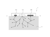
- FIG. 3 is an ab cross-sectional view of the biological signal measuring device according to the first embodiment of the present technology, which is a conceptual diagram of LDF measurement.
- FIG. 3 is a cd cross-sectional view of the biological signal measuring device according to the first embodiment of the present technology, which is a conceptual diagram of PPG measurement.
- FIG. 1 It is a figure which shows an example of division drive at the time of light emission and light reception of LD light and LED light of this technique.
- FIG. 1 It is a schematic diagram of an example of a living body signal measuring device concerning a first embodiment of this art. This is an example of a case where the biological signal measuring device has a light reception adjusting mechanism (multi-division PD). It is a schematic diagram of an example of a living body signal measuring device concerning a first embodiment of this art. This is an example of a case where the biological signal measuring device has a light reception adjusting mechanism (liquid crystal shutter). It is a schematic diagram of an example of a living body signal measuring device concerning a first embodiment of this art.
- the biological signal measuring device has a light reception adjusting mechanism (transparent part). It is a schematic diagram of an example of a living body signal measuring device concerning a first embodiment of this art. This is an example of a case where the biological signal measuring device has a light reception adjusting mechanism (optical filter). It is a schematic diagram of an example of a living body signal measuring device concerning a first embodiment of this art. This is an example of a case where the biological signal measuring device has a light reception adjusting mechanism (optical filter). It is a schematic diagram of an example of a living body signal measuring device concerning a first embodiment of this art.
- FIG. 1 It is an example of a case where the positional relationship between the first light emitting element and the second light emitting element and the light receiving element of the biological signal measuring device is adjusted.
- FIG. 1 It is a schematic diagram of an example of a living body signal measuring device concerning a first embodiment of this art. This is an example of a case where the biological signal measuring device has a light receiving area adjusting mechanism (optical filter).
- the biological signal measuring device has a light receiving area adjusting mechanism (optical filter).
- FIG. 1 It is an example of a case where the biological signal measuring device has a light receiving area adjusting mechanism (optical filter).
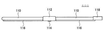
- FIG. 7 is an ab cross-sectional view of the biological signal measuring device according to the second embodiment of the present technology, which is a conceptual diagram of LDF measurement and PPG measurement. It is a figure showing an example of operation of a living body signal measuring device concerning a second embodiment of this art. It is a figure showing an example of operation of a living body signal measuring device concerning a second embodiment of this art. It is a figure showing an example of operation of a living body signal measuring device concerning a second embodiment of this art. It is a schematic diagram of an example of a living body signal measuring device concerning a second embodiment of this art. It is a block diagram showing functional composition of living body information processor 1000 of this art. It is a figure showing an example of an embodiment of measurement module 500 of this art. It is a figure showing an example of an embodiment of measurement module 500 of this art.
- Biological signal measuring device 1-1 Overview of biological signal measuring device according to present technology 1-2.
- a general reflection type PPG is composed of an LED as a light emitting element (light source) and a PD as a light receiving element (light receiver), and irradiates the living body with LED light to scatter light (non-coherent light) reflected inside the living body. ) Is measured by PD. Since hemoglobin exists in blood in the living body and has a characteristic of absorbing incident light, it is possible to measure a pulse wave signal by time-sequentially sensing the volume change of the blood vessel that changes with the pulsation of the heart. It is structured like this.
- a general LDF is composed of an LD of a light emitting element (light source) and a PD of a light receiving element (light receiver), irradiates LD light toward a living body and reflects it from a tissue that is stationary in the living body.
- the PD measures the interference between the light that is not Doppler-shifted and the light that is Doppler-shifted (coherent light) reflected from moving blood.
- the interfered light is measured as a beat signal, and the beat signal is divided into a certain time window and Fourier-transformed to obtain a frequency spectrum at each time.
- the frequency spectrum of the beat signal is distributed from about several tens Hz to several tens kHz, and its shape changes according to the speed of blood. Then, since the value obtained by multiplying the frequency spectrum in a certain time window by multiplying the frequency and standardized by the received light intensity is proportional to the blood flow velocity, a change corresponding to the blood flow velocity can be measured.
- PPG for measuring pulse and LDF for measuring blood flow have been developed as separate devices. If these two pieces of biometric information are to be measured at the same time, these two devices must be mounted and used, respectively, and the size of the device becomes two, resulting in an increase in size and a large area when mounted on a living body. The problem arises.
- an LD light source is always required to realize LDF measurement, and therefore the output of the LD light source is reduced to spontaneous emission light such as LED light. By doing so, it can be used for PPG measurement. Specifically, spontaneous emission is performed by causing the LD to emit light at a current threshold value or less, and the light emission is performed when the LD functions as an LDF, and when the PPG functions as the spontaneous emission, the spontaneous emission light is driven. It realizes the integration of these two devices.
- the light source is only one LD light source, one of the light receiving elements for LDF measurement is also used for PPG measurement, and one shared light receiving element is provided. (FIG. 1 of Patent Document 4, in particular).
- Patent Document 4 only the LD light source is used as the light source. A problem at this time is that the amount of light becomes small because the current is reduced when the LED emits light. Therefore, the present inventor considered that there is a concern that the influence of signal noise during PPG measurement may increase.
- the present inventor considered that the signal for noise removal cannot be measured.
- the present inventor uses at least two light emitting elements in a biological signal measuring device, and uses at least one light receiving element that receives light scattered in a living body, and further measures with the light receiving element. It has been found that it is important to configure the light intensity signal to be output as biometric information. Then, in the present technology, from a light emitting unit having at least a first light emitting element and a second light emitting element for irradiating the surface of a living body, and at least one for receiving light scattered in the living body by the light emitted from the light emitting unit. It is possible to provide a biological signal measuring device including a light receiving element that has the light receiving element and outputs a light intensity signal measured by the light receiving element as biological information.
- the present technology shares the light source and the light receiver in the LDF measurement and the PPG measurement, and thus it is possible to integrate the two devices of the LDF measurement device and the PPG measurement device into one device. Therefore, the present technology is preferably a biological signal measurement device for blood flow measurement and pulse measurement.
- the device according to an embodiment of the present technology can be downsized and the contact area can be reduced at the time of wearing, so that the burden on the wearer is reduced. Further, when the device is downsized, low power consumption is also realized.
- this technology can realize miniaturized multi-measurement while the influence of PPG signal noise is small. Furthermore, since the present technology allows the light source to have two wavelengths for PPG measurement, it also enables signal measurement for noise removal. In addition, in the PPG measurement of the present technology, it becomes possible to measure the oxygen saturation by using two appropriate different wavelengths.
- the present technology uses at least two light emitting elements, and (a) adjusts the light reception of one light receiving element to control the light reception of LDF and/or PPG, and/or (b) uses two light receiving elements. More preferably, the drive related to the light emission and the drive related to the light reception are controlled so that the interval value and/or the instantaneous value can be measured. At this time, it is preferable that the light receiving section used in the present technology has at least one light receiving element of (a) and/or two light receiving elements of (b). Then, it is preferable that the light receiving unit is configured to output the light intensity signal measured by one of the light receiving elements of (a) as biological information.
- the light receiving unit is configured to output the light intensity signal measured by the two light receiving elements of (b) as biological information.
- At least one of the light emitting elements of the present technology is preferably a light source that emits light having at least a long coherence length.
- at least one of the light emitting devices of the present technology is preferably a light source that emits light having a short coherence length.
- the light receiving unit has one light receiving element that also serves to measure an instantaneous value and a section value, or two light receiving elements that respectively measure an instantaneous value and a section value. It is preferable that the light emitting element is configured to be driven by dividing the light emission time. It is preferable that the light receiving element is configured to be driven by dividing the light receiving time.
- the present technology makes it possible to share one light receiving element (PD) for LDF measurement and PPG measurement by using a light reception adjustment mechanism (more preferably, a light reception area adjustment mechanism). Can reduce the effect of signal noise. Furthermore, the present technology enables miniaturization of the device itself and high-performance simultaneous measurement of pulse and blood flow. In the present technology, the number of PDs to be driven is reduced, so that power consumption is reduced. Since the PD area can be made suitable for both LDF and PPG, signals can be acquired with high accuracy (see the first embodiment described later).
- the present technology can secure a sufficient light emission intensity for PPG measurement by controlling driving related to light emission (at least two light emitting elements) and light reception (at least two light receiving elements), and highly accurately.
- LDF and PPG can be measured.
- a light source having a long coherence length is suitable for at least one of the light emitting elements. More preferably, at least two of a light receiving element that measures an instantaneous value for light having a short coherence length of the light emitting element and a light receiving element that measures an interval value for light having a long coherence length of the light emitting element are included. That is.
- a light receiving element for measuring this instantaneous value for light with a long coherence length by a light emitting element with a long coherence length it is more preferable to have a light receiving element for measuring this instantaneous value for light with a long coherence length by a light emitting element with a long coherence length, and to measure the instantaneous value with this.
- the device in which the LDF measurement and the PPG measurement are integrated is downsized. Since the number of light sources to be driven is reduced, power consumption is reduced.
- the emission intensity of PPG is sufficient, a signal can be acquired with high accuracy. Since the emission wavelengths of PPG can be set to two types, it is possible to measure oxygen saturation and a signal for noise removal (see the second embodiment described later).
- Bio signal measuring device 1 according to the present technology> The biological signal measuring device according to the present technology and each part thereof will be described in more detail below, but the present technology is not limited thereto.
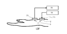
- the biological signal measuring device 1 is configured to irradiate a living body surface 2 with a light emitting unit 10 having at least a first light emitting element 11a and a second light emitting element 11b, and in a living body by light emitted from the light emitting unit 10.
- the light receiving unit 20 includes at least one light receiving element 21 that receives scattered light, and outputs a light intensity signal measured by the light receiving element 21 as biometric information.
- the housing 40 may house the light emitting unit 10, the light receiving unit 20, the signal processing unit 50, and the like. Further, some or all of the functions performed by the light emitting unit 10, the light receiving unit 20, the signal processing unit 50, and the like may be arranged outside the housing 40, or an accessible information processing apparatus (for example, a server or the like). ).
- the biological signal measuring device 1 is a biological signal measuring device for blood flow measurement and pulse measurement.
- the present technology is more preferably a photoplethysmography (PPG) measurement (preferably reflection type) and/or a laser Doppler flowmetry (LDF) measurement.
- PPG photoplethysmography
- LDF laser Doppler flowmetry
- the present technology can also measure oxygen saturation and the like.
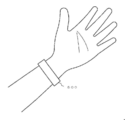
- examples of the biological surface 2 for acquiring biological information include, but are not limited to, the surfaces of the site (measurement region) of the measurement subject, such as the hands, arms, neck, and feet.
- a site where the biological information of the measurement subject can be obtained is suitable. More specifically, a site that can obtain pulse information and/or blood flow information regarding the pulse and/or blood flow of the measurement subject is more preferable, and the site can also obtain information on oxygen saturation. ..
- the light emitting unit 10 has at least two light emitting elements 11. Further, it is preferable that the light emitting element 11 is configured to be driven by dividing the time.
- a light source whose usable wavelength has a visible light region, a near infrared region or an infrared region is preferable.
- the light emitting element include, but are not limited to, an LD (Laser Diode) light source, an LED (Light Emitting Diode) light source, and a xenon light source. These light sources may be ones that can change the irradiation wavelength or ones that emit a specific wavelength.
- the LED light source can emit light in the ultraviolet wavelength region, visible light region, infrared region, or the like, and may be a monochromatic light such as a white LED, a red LED, a blue LED, or a light source capable of emitting a plurality of these colored lights.
- the LD light source is classified as a light source having a long coherence length, and the LED light source is classified as a light source having a short coherence length.
- the light emitting unit 10 may be configured to adjust the light emitted from the light source to an arbitrary irradiation wavelength with an optical filter or the like.
- the light emitting unit 10 can use a small laser or the like to emit coherent light.
- the light emitting element 11 of the LD can emit a specific wavelength (for example, a wavelength of about 850 nm).
- the light emitting unit 10 can emit visible light or the like from the light emitting element 11 of the LED in order to emit light having a short coherence length. It should be noted that sunlight, light bulbs, fluorescent lamps, LEDs, and other light have low coherence and are almost incoherent, but in general, such light may also be referred to as non-coherent light.
- the light emitting unit 10 includes at least a first light emitting element 11a and a second light emitting element 11b. Further, it is preferable that the first light emitting element 11a and the second light emitting element 11b are configured to be driven by dividing the light emission time. Further, the first light emitting element 11a and the second light emitting element 11b may be configured to perform continuous light emission and/or pulsed light emission. In order to distinguish the two light emitting elements, the first and second light emitting elements are used for convenience, but the invention is not limited thereto. As the light emitting element 11 of the present technology, at least one of the light emitting elements is preferably a light source having a long coherence length (for example, an LD light source).
- a light source having a long coherence length for example, an LD light source
- the light emitting element 11 of the present technology it is preferable to use at least two types of light sources having different coherence lengths as the light emitting element 11 of the present technology.
- one of the light emitting elements is a light source that emits at least light having a long coherence length, and the other is a light source that emits at least light having a short coherence length.
- the first light emitting element 11a is a light source that emits at least light having a long coherence length
- the second light emitting element 11b emits at least light having a short coherence length. Is preferred. Thereby, LDF measurement and PPG measurement can be performed with higher accuracy.
- the light emitting element 11 of the present technology it is preferable to use at least two types of light sources capable of irradiating different wavelengths separately or at the same time. This makes it possible to measure the influence of body movements, emit light of different wavelengths in order to remove noise, and measure oxygen saturation.
- the light emitting unit 10 may be configured to be capable of being controlled to emit light (emission wavelength, timing, etc.) by the signal processing unit 50. At this time, it is preferable that the signal processing unit 50 controls so that the light emitting element 11 and a light receiving element described later are synchronized.
- At least two or three or more light emitting elements 11 such as LDs and LEDs may be provided in the biometric information processing device (for example, a measurement module). Further, in the present technology, one or two or more light emitting units 10 having at least two light emitting elements 11 may be provided in the biological information processing device (for example, a measurement module).
- the light receiving unit 20 has a light receiving element 21 including at least one. Further, it is preferable that the light receiving element 21 is configured to be driven by dividing the time.
- the light receiving unit 20 preferably has at least one or at least two light receiving elements 21.
- the light receiving unit 20 is configured to measure the light scattered by the light emitted from the light emitting element 11 in the living body by the light receiving element 21, and output the measured light intensity signal as biological information.
- the light receiving unit 20 may output the measured light intensity signal to the signal processing unit 50 for the purpose of obtaining biological information.
- the light receiving unit 20 may output the biometric information after converting the measured light intensity signal into biometric information.
- the light receiving element 21 preferably has a photodiode (Photo Detector: PD), and examples thereof include, but are not limited to, a multi-division PD, a line sensor, and an image sensor.
- the light receiving element 21 can convert the intensity of light received by the PD into an electric signal and output the electric signal to a signal processing unit described later.
- a CCD (Charge Coupled Devices) type sensor, a CMOS (Complementary Metal Oxide Semiconductor) type sensor, or the like can be used.
- the light receiving unit 20 may include, for example, a photodiode (PD), an amplifier circuit, a filter circuit, and an analog-digital converter.
- the light receiving unit 20 may be configured to be controlled by the signal processing unit 50 to output the detection signal (timing or the like).
- one or more light receiving elements 21 such as photodiodes and sensors may be provided in the biometric information processing device (for example, a measurement module). Further, in the present technology, one or two or more light receiving units 20 having one or more light receiving elements 21 may be provided in the biological information processing apparatus (for example, a measurement module).
- the light receiving unit 20 has a relatively small light receiving area for receiving biological scattered light of light having a long coherence length and a relatively light receiving area for receiving biological scattered light of light having a short coherence length. It is possible to have a large light receiving element as one light receiving element in terms of configuration. Further, the light receiving section 20 may have these light receiving elements separately as the first and second light receiving elements.
- the light receiving section 20 preferably has a configuration in which the light reception of the light receiving element is adjusted to control these light receptions.
- the light receiving element can also be used for measuring the instantaneous value and the section value, and the LDF measurement and the PPG measurement can be performed with higher accuracy.
- the light receiving unit 20 is preferably configured so that each light receiving element can measure a section value and/or an instantaneous value. ..
- the light receiving unit 20 includes one of the light receiving elements 21 that also serves to measure the instantaneous value and the section value, or two of the first light receiving element 21a for measuring the section value and the second light receiving element 21b for measuring the instantaneous value. It is preferable to have at least.
- the signal processing unit 50 is configured to be able to control the drive of the light emitting unit 10, the irradiation pattern (for example, irradiation timing, irradiation time, irradiation interval, irradiation intensity, etc.).
- the signal processing unit 50 may control the driving of the light emitting elements 11,... Through the light emitting unit 10.
- the signal processing unit 50 can perform control such that the light emitting element 11 is driven by dividing the light emitting time.
- the signal processing unit 50 is configured to control the drive of the light receiving unit 20 and the light receiving pattern (for example, control of the light receiving element, light receiving timing, light receiving time, light receiving interval, light receiving sensitivity, etc.).
- the signal processing unit 50 may control driving of the light receiving elements 21,... Through the light receiving unit 20.
- the signal processing unit 50 can perform control such that the light receiving element 21 drives by dividing the light receiving time. Further, the signal processing unit 50 may control the light emitting element 11 and the light receiving element 21 to be synchronized.
- the signal processing unit 50 may control the light receiving adjustment mechanism.
- the signal processing unit 50 can control the light receiving area adjustment mechanism 30.
- the liquid crystal shutter can function as a shutter (open/close) by controlling the transmittance of light by modulating the applied voltage, and can also be used as a variable filter.
- the signal processing unit 50 can control the first light receiving element 21a that receives the biological scattered light and measures the interval value, and the second light receiving element 21b that receives the biological scattered light and measures the instantaneous value.
- the signal processing unit 50 can perform these controls when the first light receiving element 21a measures an instantaneous value or when the second light receiving element 21b measures a section value.
- the signal processing unit 50 can control the light emitting elements 11,... That emit light emitted to generate the biological scattered light.
- the signal processing unit 50 can obtain biological information based on the light intensity signal output from the light receiving element 21 and output the biological information.
- a light emitting section 10 having at least a first light emitting element 11a and a second light emitting element 11b for irradiating a living body surface, and light scattered in a living body by light emitted from the light emitting section.
- a light receiving section 20 having a light receiving element 21 formed of at least one.
- the light receiving unit 20 is configured to output the light intensity signal measured by the light receiving element 21 as biometric information.
- the light receiving unit 20 according to the first embodiment of the present technology includes at least one light receiving element 21 that also serves to measure an instantaneous value and a section value.
- the light receiving unit 20 of the first embodiment has a light receiving adjustment mechanism of the light receiving element 21 corresponding to the biological scattered light by each light emitted from the light emitting unit 10. It is preferable that the first light emitting element 11a is configured to continuously emit light between the light emission of the second light emitting element 11b. The second light emitting element 11b is preferably configured to emit pulsed light.
- the present technology it is possible to share one light receiving element (PD) for LDF measurement and PPG measurement by using the light receiving adjustment mechanism, and thus, both LDF and PPG can reduce signal noise. The impact can be reduced. Furthermore, the present technology enables miniaturization of the device itself and high-performance simultaneous measurement of pulse and blood flow. In the present technology, the number of PDs to be driven is reduced, so that the power consumption is reduced. Since the PD area can be made suitable for both LDF and PPG, signals can be acquired with high accuracy. Note that the effects described here are not necessarily limited, and may be any of the effects described in this specification.
- one light receiving element for LDF measurement is also used for PPG measurement, and the PD is shared.
- the PD of the LDF is used as the PD of the PPG as in Patent Document 4
- the area of the PD is small, so that the signal of the LDF does not increase the influence of noise when functioning as the LDF, but functions as the PPG.
- the present inventor has considered that it is assumed that the PPG signal is greatly affected by noise when it is performed.
- the PD of PPG is used as the PD of LDF
- the influence of noise on the signal of PPG is small because the area of PD is large, but it is assumed that the influence of noise is large on the signal of LDF.
- the amount of change in light due to absorption measured is small, so that the influence of noise on signals relatively increases in the PPG.
- the light receiving area and the light receiving distance for obtaining good accuracy are LDF measurement. Since there is a difference between the PPG measurement and the PPG measurement, a large amount of signal noise occurs in either of them. Therefore, in the conventional technology, when the LDF measurement light receiving element and the PPG measurement light receiving element are shared as one, both the pulse measurement and the blood flow measurement cannot be performed accurately. That is, in the prior art, there was a technical difficulty in using one light receiving element for LDF and PPG measurement.
- the present inventor has found that the above technical difficulty can be overcome by using the light receiving adjustment mechanism according to the present technology. Accordingly, in the first embodiment of the present technology, it is possible to appropriately adjust the light receiving area and/or the light receiving distance (for example, position or arrangement) suitable for both LDF measurement and PPG measurement. As a result, both the LDF signal and the PPG signal can be acquired with high accuracy. Further, by sharing the light receiving element, the device in which the LDF measurement and the PPG measurement are integrated can be downsized. Since the light receiving element is shared and the number of light receiving elements to be driven is reduced, the power consumption of the device including the pulse measurement and the blood flow measurement is reduced.
- both the pulse measurement and the blood flow measurement can be accurately performed by the light receiving adjustment mechanism of the present technology.
- the light receiving adjustment mechanism (more preferably, the light receiving area adjusting mechanism) of the present technology, it is possible to measure the instantaneous value and the section value with one light receiving element. Since the number of light receiving elements can be reduced, the device itself can be further downsized and the power consumption can be reduced.
- the light-receiving area adjusting mechanism 30 provided in the light-receiving section 20 is means for making the light-receiving area of the light-receiving element 21 substantially different for each of the light-emitting elements 11. It is preferable that the light receiving area adjustment mechanism 30 has a configuration that reduces the light receiving area of light having a long coherence length and/or a configuration that increases the light receiving area of light having a short coherence length. Further, it is preferable that the light receiving area adjusting mechanism 30 is adjusted so that the light receiving area of the light emitting element for light having a long coherence length is relatively smaller than the light receiving area for light having a short coherence length. ..
- the LDF measurement accuracy is improved by reducing the light receiving area for biological scattered light having a long coherence length. Further, in the light receiving element, the PPG measurement accuracy is improved by increasing the light receiving area for biological scattered light of light having a short coherence length.
- Examples of the light-receiving area adjusting mechanism 30 of the light-receiving unit 20 include, but are not limited to, an optical filter 31, a multi-segment photodiode 33, a liquid crystal shutter 34, and the like. More specifically, for example, an optical filter having a filter portion and an open portion, a multi-division PD by ON/OFF selection, a liquid crystal shutter by voltage application, and the like can be mentioned, but the invention is not limited thereto. It is preferable to use one or two or more selected from these.
- Examples of the light receiving distance adjusting mechanism of the light receiving unit include, but are not limited to, a mechanism for adjusting the position of the light receiving element, adjusting the arrangement between the respective units, and the like. It is preferable that the position adjusting mechanism of the light receiving element in the light receiving distance adjusting mechanism is configured to adjust the distance between the light emitting element 11 and the light receiving element 21 that receives the biological scattered light due to the light emission. .. The larger the distance between the living body surface 2 and the light receiving surface of the light receiving element 21, the smaller the influence of signal noise at the time of LDF measurement, and thus a better signal can be acquired.
- examples of the distance adjustment include the thickness adjustment of the optical filter 31, the thickness adjustment by the transparent portion 35, and the adjustment by a vertical movement mechanism (for example, a rack and pinion mechanism).
- the transparent portion 35 is not particularly limited, but a material that has little or no influence on the biological scattered light of the LDF measurement and the biological scattered light of the PPG measurement is suitable.
- the arrangement adjusting mechanism between the respective units in the light receiving distance adjusting mechanism includes, but is not limited to, a mechanism for adjusting the arrangement of each light emitting element 11 or each light receiving element 21. Further, it is preferable that the arrangement adjusting mechanism between the respective parts is configured to adjust the distance between the living body surface 2 and the light receiving surface of the light receiving element 21. Thereby, the distance between each part can be adjusted arbitrarily.
- the light receiving adjustment mechanism of the present technology examples include, but are not limited to, the light receiving area adjusting mechanism 30 and/or the light receiving distance adjusting mechanism. Further, each may be used alone, or both may be used in combination.
- the PD area is suitable for both LDF measurement and PPG measurement, and thus signals in these measurements can be acquired with high accuracy.
- the LDF measurement signal can be acquired with higher accuracy by separating these distances.
- the in-vivo depth (shallow depth) of the blood vessel to be measured can be adjusted by adjusting the positional relationship between these elements.
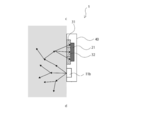
- FIG. 3 is a schematic diagram of the biological signal measuring device 1 according to the first embodiment of the present technology. As shown in FIG. 3, the biological signal measuring device 1 according to the first embodiment scatters in a living body, and a light emitting unit 10 having at least two light emitting elements 11 that cause light to enter the living body from the living body surface 2. A light receiving unit 20 having at least one light receiving element 21 that receives light and outputs a light intensity signal is provided.
- the light receiving section 20 has a light receiving adjustment mechanism between the living body surface 2 and the light receiving element 21.
- the light receiving adjustment mechanism uses an optical filter 31, which is one of the light receiving area adjustment mechanisms 30. It is preferable that the optical filter 31 has a part that is not arranged facing the light receiving element 21, and that the part is arranged at various distances from the light emitting element having a long coherence length. Further, the structure of the optical filter 31 can adopt various forms including a part which is not arranged facing the light receiving element 21.
- the optical filter 31 includes a filter portion and a portion (also referred to as an “open portion”) 32 that opens a part of an optical path to the light receiving element instead of covering the entire light receiving element with the filter (for example, an opening 32 near the center). ), and have.
- the open portion 32 is a portion through which biological scattered light can pass without passing through the filter portion.
- the filter portion does not pass the biological scattered light of the LDF, and the open portion allows the biological scattered light of the LDF to pass.
- PPG measurement the biological scattered light of PPG passes through both the filter part and the open part.
- the light receiving unit 20 can output the light intensity signal measured by the light receiving element 21 for the purpose of creating biological information. Further, the light receiving section 20 can output the light intensity signal measured by the light receiving element 21 as the created biometric information. Also, these operations may be performed in cooperation with the signal processing unit 50. Furthermore, the biological signal measuring device 1 according to the first embodiment may include a signal processing unit 50 that outputs biological information based on the optical intensity signal output from the light receiving element as biological information. The signal processing unit 50 can control the light emission of the light emitting element and the light reception of the light receiving element by instructing the light emitting unit 10 and the light receiving unit 20. It is preferable that the first light emitting element 11a is configured to continuously emit light between the light emission of the second light emitting element 11b.
- the signal processing unit 50 can control the first light emitting element 11a to continuously emit light between the light emission of the second light emitting element 11b. At this time, the signal processing unit 50 controls the light-receiving element 21 to receive the biological scattered light derived from the light emission of the first light-emitting element, and controls to measure it as a light intensity signal for the interval value, and/or It is possible to control so that the biological scattered light derived from the light emission of the two light emitting elements is received by the light receiving element 21 and is measured as a light intensity signal for an instantaneous value.
- the second light emitting element 11b is preferably configured to emit pulsed light.
- the signal processing unit 50 can control the second light emitting element 11b to emit pulsed light, and can also control the light receiving element 21 to receive light correspondingly.
- the biological signal measuring device 1 further includes a housing 40, and the housing 40 is provided with the light emitting element 11, the light receiving element 21, and the optical filter 31.
- the housing 40 may be provided with the light emitting unit 10 and the light receiving unit 20, and these may be integrated. This facilitates downsizing of the biological signal measuring device.
- an LD light source (preferably an infrared LD light source) is used as the first light emitting element 11a, and an LED light source (preferably visible light LED) is used as the second light emitting element 11b.
- the optical filter 31 it is possible to use a combination of portions having different transmission characteristics depending on the wavelength. Accordingly, it is possible to provide an optical filter that makes the light receiving area of the light receiving element substantially different for each light emission. It is preferable that the optical filter 31 does not transmit light having at least one wavelength. It is preferable that the optical filter 31 is not arranged in a part facing the light receiving surface of the light receiving element 21. Furthermore, it is preferable to provide an opening 32 that allows the biological scattered light to pass through as it is inside the optical filter.
- the material of the optical filter 31 is preferably one that does not allow light with a long coherence length to pass through but allows light with a short coherence length to pass through.
- the specific material of the optical filter is not particularly limited, and examples thereof include a resin film and glass, and a known material can be appropriately selected according to the target wavelength range.
- the resin film include polycarbonate resin and methacrylic resin
- examples of the glass material include soda lime glass and quartz glass, but are not particularly limited thereto.
- LD light and LED light are driven by dividing the time.
- the division drive can be controlled by the signal processing unit 50.
- the light-receiving element 21 measures the instantaneous value by sampling in response to the light emission of the LED, and/or continuously measures the interval in which light is emitted in response to the light emission of the LD.
- the light receiving unit 20 of the first embodiment performs LDF measurement.
- the living body scattered light derived from the LD passes through the opening 32 near the center of the optical filter 31, but cannot pass through the optical filter portion other than the opening 32. Therefore, the light receiving element 21 receives the biological scattered light derived from the LD in a small area.
- the biological scattered light is a good signal because the LDF signal noise decreases as the PD light receiving area decreases.
- the light receiving unit 20 of the first embodiment performs PPG measurement
- the biological scattered light from the LED passes through the entire optical filter 31 (specifically, the filter portion and the opening 32 portion). Therefore, the light receiving element 21 receives light with a large light receiving area.
- the biological scattered light is a good signal because the PPG signal noise decreases as the PD light receiving area increases.
- the device itself can be downsized by adopting the optical filter 31 which is one of the light receiving adjustment mechanisms. Moreover, this makes it possible to measure the pulse and blood flow signals with higher accuracy.
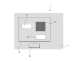
- Example 2 of biological signal measuring device according to first embodiment> An example 2 of the biological signal measuring device according to the first embodiment of the present technology will be described with reference to FIG. 7, but the present technology is not limited thereto. The description of the configuration overlapping with the configuration described above will be appropriately omitted.
- Example 2 of the biological signal measuring device of the first embodiment is an example of the case where the light receiving area adjustment mechanism is a mechanism in which the light receiving elements are spatially divided, and the present invention is not limited to this. Not done.
- the multi-segment photodiode 33, a photodiode using a multi-segment liquid crystal shutter, and the like can be given, but the present technology is not limited thereto.
- the light emitting element and the light receiving element are synchronized.
- the PD of each divided portion adjusts the light receiving area in synchronization with the light emitting element.
- the multi-divided PD can be controlled to receive light in a small area in response to the light emission of the light emitting element for LDF.
- the multi-division PD can be controlled to receive light in a large area in response to the light emission of the light emitting element for PPG.
- the control can be performed by, for example, the signal processing unit 50 or the like.
- the light receiving unit 20 of the biological signal measuring device is a multi-division PD composed of 9 sections
- the PD in the center of 1 section corresponding to the LD emission receives the biological scattered light from the LD and also emits the LED.
- the living body scattered light from the LED is received by the PDs of the entire 9 sections.
- the change of the light receiving area of the PD may be controlled by the signal processing unit 50. As a result, the pulse and blood flow signals can be measured with higher accuracy.
- the distance relationship between the light emitting element and the light receiving element can be adjusted by adjusting the operation of each PD in the multi-split PD 33. For example, the PD section close to the light emitting element is operated to receive light to make the measurement depth shallow, or the PD section far from the light emitting element to be operated to receive light to make the measurement depth deep. This makes it possible to adjust the shallow depth of measurement.
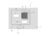
- Example 3 of biological signal measuring device according to first embodiment> An example 3 of the biological signal measuring device according to the first embodiment according to the present technology will be described with reference to FIG. 8, but the present technology is not limited thereto. The description of the configuration overlapping with the configuration described above will be appropriately omitted.
- Example 3 of the biological signal measuring apparatus according to the first embodiment is an example in which the light receiving area adjusting mechanism is a mechanism including the liquid crystal shutter 34 between the living body surface 2 and the light receiving element 21 as shown in FIG. ..
- the liquid crystal shutter 34 can change the light transmission characteristics according to a change in voltage.
- the liquid crystal shutter 34 of the present technology may not be provided with the liquid crystal shutter corresponding to the opening portion of the optical filter unlike the optical filter of the present technology, and may be configured to be provided with the liquid crystal shutter corresponding to the filter portion of the optical filter. Further, the liquid crystal shutter 34 of the present technology may be a multi-division liquid crystal shutter such as a multi-division PD.
- the voltage applied to the liquid crystal shutter 34 is synchronized with the light emitting element and the light receiving element, and the light receiving area is adjusted.
- the light receiving area adjusting mechanism can control so that light passes through only a small area of the liquid crystal shutter in response to light emission of the light emitting element for the LDF so as to reduce the light receiving area and receive light. Further, the light receiving area adjusting mechanism can control so that light passes through a large area of the liquid crystal shutter and the light receiving area is increased to receive light in response to the light emission of the light emitting element for PPG.
- the control can also be performed by the signal processing unit 50 or the like, for example. As a result, the pulse and blood flow signals can be measured with higher accuracy.
- the distance relationship between the light emitting element and the light receiving element is also adjusted by adjusting the position of the light receiving section of the light receiving area of the light receiving element by using the multi-divided liquid crystal shutter as described in the above-mentioned multi-divided PD. It is possible. This makes it possible to adjust the shallow depth of measurement.
- Example 4 of the biological signal measuring device according to the first embodiment is an example in which the light receiving distance adjusting mechanism is a mechanism including a transparent portion 35 between the living body surface 2 and the light receiving element as shown in FIG. 9.
- the transparent portion 35 is preferably a member that transmits biological scattered light (more preferably, biological scattered light of LDF).
- the transparent part 35 and the optical filter 31 it is more preferable to dispose the transparent portion 35 at a position facing the light receiving element 21. More preferably, the optical filter 31, the transparent portion 35, and the light receiving element 21 are arranged in this order from the light receiving direction. At this time, it is more preferable to dispose the transparent portion 35 facing the light receiving element 21 and dispose the optical filter 31 on the transparent portion 35. As a result, the pulse and blood flow signals can be measured with higher accuracy, and the size of the device itself can be reduced.
- the material of the transparent portion 35 is not particularly limited, and examples thereof include a resin film and glass, and a known material can be appropriately selected according to the wavelength range of passing light.
- the resin film include polycarbonate resin and methacrylic resin
- examples of the glass material include soda lime glass and quartz glass, but are not particularly limited thereto.
- the transparent portion 35 is provided between the light receiving element 21 and the filter opening surface. Thereby, LDF measurement and PPG measurement can be performed with higher accuracy.
- Example 5 of biological signal measuring device according to first embodiment> An example 5 of the biological signal measuring device according to the first embodiment of the present technology will be described with reference to FIGS. 10 and 11, but the present technology is not limited thereto. The description of the configuration overlapping with the configuration described above will be appropriately omitted.
- Example 5 of the biological signal measuring device is an example of the case where the light receiving area adjustment mechanism is a mechanism that adjusts the open portion of the optical filter 31.
- the light-receiving element 21 can be provided with the open portion 32 that is a light-receiving portion for LDF measurement.
- Adjustment of the open portion of the optical filter may be performed by using a moving mechanism such as a slide mechanism or a rack and pinion mechanism, which can be controlled by the signal processing unit 50 or the like.
- the optical filter may be fixed with an adhesive or a fixing metal fitting after the positional relationship of the open portion of the optical filter is adjusted. Since the light receiving area can be adjusted by adjusting the positional relationship without processing the notch or the opening in the optical filter 31 itself, the man-hour of the manufacturing process of the optical filter can be omitted, and the light receiving area can be controlled by simpler control. Adjustments can be made. By adjusting the area of the open portion 32, the light receiving area corresponding to the light emission can also be adjusted, so that the light receiving area for the LD-derived biological scattered light can be reduced, and the LD-derived biological scattered light can be satisfactorily. Can receive light.
- the light receiving area for the biological scattered light from the LED can be increased, and the biological scattered light from the LED can be favorably received.
- the pulse and blood flow signals can be measured with higher accuracy, and the size of the device itself can be reduced.
- Example 5 of the biological signal measuring device of the first embodiment is a case where the light receiving position adjusting mechanism is a mechanism for adjusting the position of the open portion of the optical filter 31.
- the light receiving position adjusting mechanism is a mechanism for adjusting the position of the open portion of the optical filter 31.
- the blood flow information is different.
- the larger the distance between the light emitting element 11 for LDF and the light receiving element 21 (light receiving portion 32 for LDF) the deeper the blood vessel in the living body can be measured.
- the smaller the distance between the light emitting element 11 for LDF and the light receiving element 21 (light receiving portion 32 for LDF) the more shallow the blood vessel in the living body can be measured. In this way, the depth (shallow depth) of the blood vessel to be measured can be changed by changing the position of the optical filter 31 and adjusting the lacking portion (opening portion).
- Example 6 of biological signal measuring device according to first embodiment> The example 6 of the biological signal measuring device according to the first embodiment according to the present technology will be described with reference to FIG. 12, but the present technology is not limited thereto. The description of the configuration overlapping with the configuration described above will be appropriately omitted.
- An example 6 of the biological signal measuring device of the first embodiment is an example of a case where the light receiving distance adjusting mechanism is a mechanism for adjusting the light receiving elements 21a and 11b and the light receiving element 21 on the plane as shown in FIG. Is.
- the positional relationship between the light emitting element 11 and the light receiving element 21 may be adjusted by using, for example, a moving mechanism such as a slide mechanism or a rack and pinion mechanism, or may be fixed with an adhesive or a fixing metal fitting after the adjustment. .. These can be controlled by the signal processing unit 50 and the like. Further, when fixing the light emitting element 11 and the light receiving element 21 to the housing 40, their arrangement may be adjusted. The larger the distance between the light emitting element 11 for LDF and the light receiving element 21 for PPG, the deeper the blood vessel in the living body can be measured. The smaller the distance between the light emitting element 11 for LDF and the light receiving element 21 for PPG, the more shallow the blood vessel in the living body can be measured. In this way, by changing the positions of the light emitting element and the light receiving element, the depth (shallow depth) of the blood vessel to be measured can be changed.
- Examples 7 and 8 of the biological signal measuring device include the light emitting unit 10 including the first light emitting element 11a and the second light emitting element 11b, and the light receiving unit 20 including the optical filter 31 having the light receiving element 21 and the opening 32. .. Further, it is preferable that the light emitting unit 10 and the light receiving unit 20 are housed in the housing 40.
- the optical filter 31 does not cover the filter portion and the light receiving element entirely with the filter, but a portion that opens a part of the light receiving element (for example, It is preferable to provide an opening 32 near the center).
- the open portion is a portion through which biological scattered light can pass without passing through the filter portion.
- LDF measurement the biological scattered light is not passed through the filter portion, and the biological scattered light is passed through the open portion.
- PPG measurement the biological scattered light passes through both the filter part and the open part. Thereby, the accuracy of LDF measurement and PPG measurement can be improved.
- the open part and shape of the optical filter are not particularly limited, and can take various forms.
- the open portion may be a space through which light can pass or a material through which coherent light can pass.
- the above-mentioned material of the transparent portion is preferable, and examples thereof include plastic resin and glass, but are not particularly limited.
- FIG. 13 shows an example in which the opening (opening portion) of the optical filter is circular, but the shape of the opening in the present technology is not particularly limited, and for example, a polygonal shape (for example, triangle, quadrangle, square, rectangle). , Pentagon, hexagon, etc.), elliptical shape, circular shape, star shape and the like.
- a polygonal shape for example, triangle, quadrangle, square, rectangle. , Pentagon, hexagon, etc.
- elliptical shape circular shape, star shape and the like.
- the shape of the optical filter is a shape having a cutout portion or a cutout portion (open portion), but the shape of the filter in the present technology is not particularly limited, and for example, a polygonal shape (for example, a concave portion or a convex portion) Shapes having portions, quadrilateral to hexagonal shapes, etc.), elliptical shapes, circular shapes, star shapes and the like.
- Biological Signal Measuring Device 1 According to Second Embodiment>
- the second embodiment will be described in more detail below with reference to FIGS. 15 to 20, but the present technology is not particularly limited to this. ⁇ 1.
- the biological signal measuring device according to the present technology> and the description of the configuration overlapping the configuration of the first embodiment will be appropriately omitted.
- the light source is shared and the LDF measurement device and the PPG measurement device can be integrated into one device, and the device can be downsized.
- the number of driven light sources is reduced, so that the power consumption is reduced.
- the intensity of PPG light emission is sufficient, a signal can be acquired with high accuracy. Since the present technology has two emission wavelengths of PPG, it is possible to measure oxygen saturation and a signal for noise removal. Note that the effects described here are not necessarily limited, and may be any of the effects described in this specification.
- the light receiving unit 20 has at least two first light receiving elements 21a for measuring interval values and second light receiving elements 21b for measuring instantaneous values.
- the light receiving unit 20 of the second embodiment has a configuration in which biological scattered light emitted by each light emitted from the light emitting unit 10 is received by the first light receiving element 21a and the section value is measured, and the second light receiving element 21b. It is configured to receive light at and measure an instantaneous value.
- the first light receiving element 21a for measuring the interval value receives biological scattered light due to light having a long coherence length of the light emitting element
- the second light receiving element 21b for measuring the instantaneous value is the light emitting element.
- the first light emitting element 11a is preferably configured to continuously emit light between the light emission of the second light emitting element 11b.
- the second light emitting element 11b is preferably configured to emit pulsed light.
- the first light receiving element 21a has a configuration for receiving biological scattered light by continuous light emission of the first light emitting element to measure a section value
- the second light receiving element 21b has the second light emitting element. It is preferable to have a configuration for receiving a part of the biological scattered light by the pulsed light emission and the biological scattered light by the continuous light emission of the first light emitting element to measure the instantaneous value.
- the first light emitting element 11a is configured to perform continuous light emission and pulse light emission in random order between the light emission of the second light emitting element 11b.
- the second light emitting element 11b is preferably configured to emit pulsed light.
- the first light receiving element 21a receives the biological scattered light by the continuous light emission of the first light emitting element to measure the section value, and the second light receiving element 21b emits the pulsed light of the second light emitting element.
- the living body scattered light by and the living body scattered light by pulse emission of the first light emitting element are received to measure an instantaneous value.
- the distance between the light emitting element 11 and the light receiving element 21 that receives the biological scattered light due to the light emission of the light emitting element is adjusted.
- the light receiving distance adjusting mechanism of the above-described first embodiment may be adopted.
- the position adjustment of the light receiving element and the arrangement adjustment between the respective parts described above are suitable.
- the position of the light receiving element in the light receiving distance adjusting mechanism is preferably adjusted by adjusting the distance between the light emitting element 11 and the light receiving element 21 that receives the biological scattered light due to the light emission. It is preferable to adjust the arrangement of the light emitting elements 11 and the light receiving elements 21 for the arrangement adjustment between the respective parts in the adjustment of the light receiving distance.
- FIG. 15 is a schematic diagram of the biological signal measuring device 1 according to the second embodiment of the present technology.
- the biological signal measuring device 1 according to the second embodiment includes a light emitting unit 10 having at least two light emitting elements 11 that cause light to enter the living body from the living body surface 2 and scattering in the living body.
- the light receiving unit 20 having at least two light receiving elements 21 for receiving the received light and outputting a light intensity signal is provided.
- the signal processing unit 50 may be provided.
- the signal processing unit 50 may control the operations of the light emitting element 11 and the light receiving element 21, and the operations of the light emitting section 10 and the light receiving section 20.
- the signal processing unit 50 is configured to be able to output biometric information based on the light intensity signal output from the light receiving element.
- the light emitting element a light source whose usable wavelength has a visible light region, a near infrared region or an infrared region is preferable.
- the light receiving element 21 preferably has a photodiode (Photo Detector: PD), and examples thereof include, but are not limited to, a multi-division PD, a line sensor, and an image sensor.
- PD photodiode
- it is preferable that the light emitting unit 10 and the light receiving unit 20 are housed in the housing 40. As a result, the pulse and blood flow signals can be measured with higher accuracy, and the size of the device itself can be reduced.
- the light emitting unit 10 includes a first light emitting element 11a and a second light emitting element 11b.
- the first light emitting element 11a may be a light source that emits light having a long coherence length (so-called coherent light).
- the second light emitting element 11b may be a light source that emits light having a short coherence length (so-called incoherent light).
- the first light emitting element 11a may be configured to continuously emit light between the light emission of the second light emitting element 11b.
- the second light emitting element 11b may be configured to emit pulsed light.
- the first light emitting element 11a may be configured to perform continuous light emission and pulse light emission in random order between the light emission of the second light emitting element 11b.
- the light receiving unit 20 includes at least two first light receiving elements 21a for measuring interval values and second light receiving elements 21b for measuring instantaneous values.
- the light receiving unit 20 receives the biological scattered light emitted from the first light emitting element 11a of the light emitting unit 10 by the first light receiving element 21a and measures the section value (the area where the light receiving element 1 is driven). It is preferable to have (see FIG. 17 and FIG. 16).
- the first light receiving element 21a for measuring the section value is preferably configured to receive biological scattered light due to light having a long coherence length of the light emitting element.
- the light receiving section 20 receives the biological scattered light emitted from the second light emitting element 11b of the light emitting section 10 by the second light receiving element 21b and measures an instantaneous value (each area for driving the light receiving element 2). It is preferable to have a configuration (see FIGS. 17 and 16).
- the second light receiving element 21b for measuring the instantaneous value is preferably configured to receive biological scattered light by light having a short coherence length of the light emitting element.
- the first light receiving element 21a has a configuration for receiving biological scattered light by continuous light emission of the first light emitting element to measure a section value, and the second light receiving element 21b has pulsed light emission of the second light emitting element.
- the first light receiving element 21a receives the biological scattered light by the continuous light emission of the first light emitting element to measure the section value
- the second light receiving element 21b uses the pulsed light emission of the second light emitting element. It is preferable that the living body scattered light and the living body scattered light generated by pulse emission of the first light emitting element be received to measure an instantaneous value.
- the light receiving unit 20 can output the light intensity signal measured by the light receiving element 21 as biological information. Also, these operations may be performed in cooperation with the signal processing unit 50.
- Example 1 of the second embodiment will be described below with reference to FIG. 15 and the like, but the present technology is not limited to this.
- an LD preferably an infrared LD
- a second light emitting element 11b is used.
- Is used as an LED (preferably a visible light LED), and at least two light emitting elements having different wavelengths are used.
- the first light receiving element 21a it is preferable to use a PD having a relatively smaller light receiving area than the second light receiving element 21b.
- the light receiving section 20 having the first light receiving element 21a may have the above-described light receiving adjustment mechanism.
- the LD light of the first light emitting element 11a and the LED light of the second light emitting element 11b are driven by dividing the time (each area of the light emitting element intensity).
- the second light receiving element 21b samples the light emission of the second light emitting element 11b, and also similarly samples the light emission of the first light emitting element 11a to measure an instantaneous value (each area for driving the light receiving element 2). ..
- the 1st light receiving element 21a measures the area which the said 1st light emitting element 11a light-emits with respect to the light emission of the 1st light emitting element 11a (area of the light receiving element 1 drive).
- the second light emitting element 11b can be incident on the living body with sufficient intensity as a visible light LED, it can be measured in a state where the influence of the noise of the PPG signal is small. .. Further, since the LD light scattered in the living body from the first light emitting element 11a is received by the PD of the second light receiving element 21b, information of different wavelengths can be acquired as PPG, and noise removal from two different wavelengths can be performed. Can measure signals. Further, when the two wavelengths of the first light emitting element 11a and the second light emitting element 11b are optimally different, the oxygen saturation can be measured better.
- the LDF measurement and the PPG measurement are integrated and the light source is shared, by adopting the configuration of the example 1 of the second embodiment, it is possible to realize the downsizing of the apparatus itself and to achieve higher accuracy.
- the pulse and blood flow signals can be measured. Furthermore, it is possible to measure a signal for noise removal. In addition, by using two different optimal wavelengths in PPG, it is possible to measure oxygen saturation better.
- Example 2 of biological signal measuring device > The operation of Example 2 of the second embodiment will be described below with reference to FIG. 18 and the like, but the present technology is not limited to this. The description of the configuration overlapping with the configuration described above will be appropriately omitted.
- the relative light receiving area may be adjusted using the above-described light receiving area adjusting mechanism. As shown in FIG. 18, the light having a short coherence length of the second light emitting element 11b emits pulsed light, and the light having a long coherence length of the first light emitting element 11a has a continuous light emitting portion and a pulse light emitting portion. (Each area of light emitting element strength).
- the second light receiving element 21b having a relatively large light receiving area is configured to sample pulse light emission with a short coherence length and pulse light emission with a long coherence length to measure an instantaneous value (for driving the light receiving element 2). Each area).
- the first light receiving element 21a having a relatively small light receiving area is configured to measure a section where light is emitted for continuous light emission having a long coherence length (each area for driving the light receiving element 1). Since the light emission of LD in the LDF has a long light emission time, it is necessary to reduce the light emission intensity to a predetermined value that does not harm the skin and eyes from the viewpoint of biological safety.
- the instantaneous intensity can be increased as compared with the LD light.
- the LD light is used for the PPG, a part of the LD light is pulsed and adjusted so that the intensity of the PPG signal becomes sufficient. At this time, it is necessary to have a strength that does not pose a problem from the viewpoint of biological safety.
- Example 3 of biological signal measuring device > The operation of Example 3 of the second embodiment will be described below with reference to FIG. 19 and the like, but the present technology is not limited to this. The description of the configuration overlapping with the configuration described above will be appropriately omitted.
- the relative light receiving area may be adjusted using the above-described light receiving area adjusting mechanism.
- the irradiation intensity of each light emitting element can be irradiated like each area of the light emitting element intensity
- the second light receiving element 21b can be instantaneously irradiated like each area of driving the light receiving element 2.
- the value can be measured, and the first light receiving element 21a can measure a section value like an area where the light receiving element 1 is driven.
- the second embodiment of the present technology is not particularly limited to the operations of Examples 1 to 3 described above.
- Example 4 of biological signal measuring device > Examples 1 and 4 of the second embodiment will be described below with reference to FIGS. 15 and 20, but the present technology is not limited thereto. The description of the configuration overlapping with the configuration described above will be appropriately omitted.
- FIGS. 15 and 20 for example, the positional relationship between the first light emitting element 11a that emits LD light and the first light receiving element 21a for LDF can be changed.
- the measured blood flow information is different.
- the distance between the light emitting element and the light receiving element is large, it is possible to measure the result at a deeper part in the living body.
- the depth (shallow depth) of the blood vessel to be measured in the living body can be changed by changing the positional relationship of the light receiving element corresponding to the light emitting element. Further, by changing the positional relationship between the second light emitting element 11b that emits the LED and the second light receiving element 21b for PPG, the depth (shallow depth) of the blood vessel to be measured in the living body can be changed. ..
- the biological information processing apparatus 1000 includes the biological signal measuring apparatus 1 according to the present technology described above.
- the biological information processing apparatus 1000 receives at least one of a light emitting unit having at least a first light emitting element and a second light emitting element for irradiating a living body surface, and light scattered in a living body by light emitted from the light emitting unit. And a light receiving section which outputs a light intensity signal measured by the light receiving element as biological information (see FIG. 21).
- the biological information processing apparatus 1000 according to the present technology may be constructed as a system.
- the biological signal measuring device 1 of the present technology is preferably configured to use at least two light emitting elements and adjust the light receiving area of one light receiving element to control the light reception of the LDF and/or the PPG. .. And/or the biological signal measuring apparatus 1 of the present technology uses at least two light emitting elements, and performs light emission-related and light-reception-related driving so that a section value and/or an instantaneous value can be measured using two light receiving elements. It is preferably configured to control.
- the biological signal measuring device according to the first embodiment and the biological signal measuring device according to the second embodiment described above may be mentioned, but the invention is not limited thereto.
- measurement of the biological information of the person to be measured is performed. More specifically, in an embodiment of the present technology, in order to obtain pulse information and/or blood flow information regarding the pulse and/or blood flow of the measurement subject, photoelectric volumetric pulse wave (PPG) measurement and/or Laser Doppler blood flow meter (LDF) measurement is performed.
- PPG photoelectric volumetric pulse wave
- LDF Laser Doppler blood flow meter
- biometric information of PPG include pulse information such as pulse rate, pulse wave, oxygen saturation, oxygen saturation information, and the like.
- the biometric information of the LDF include average blood flow velocity, blood flow volume, blood flow information such as velocity distribution of particles in blood vessels, and the like.
- a region (measurement region) of the measurement subject such as a hand, an arm, a neck, or a foot, is irradiated with light, and a substance moving in the blood vessel of the measurement subject or Detects light scattered by stationary living tissue.
- the detected light specifically, the detection signal
- the detected light is processed to obtain the biological information of the PPG measurement and/or the biological information of the LDF measurement, and further the pulse information and/or the blood flow information. Etc. can be obtained.
- the biological information processing apparatus 1000 includes at least the biological signal measuring apparatus 1 according to the present technology.
- the present technology may include at least the biological signal measurement device 1 of the present technology, and further, by using various devices, networks, and the like, the biological information processing system of the present technology may be constructed.
- FIG. 22 shows a measurement module 500 including the biological signal measuring apparatus 1 of the present technology.
- the biological information processing apparatus 1000 may include an information display device that displays measurement results and the like to the user.
- the user includes a person to be measured who is a person to be measured by PPG measurement and/or LDF measurement, a person other than the person to be measured who uses the information processing system, and the like.
- the light emitting unit (also referred to as an irradiation unit) 501 has at least two light sources (light emitting elements), and irradiates irradiation light having a predetermined wavelength from the light sources toward a measurement region (part of the body) of the measurement subject. To do.
- the light emitting unit 501 is configured to control the driving of the light emission of each of the first light emitting element and/or the second light emitting element.
- the wavelength of the irradiation light emitted by the light emitting unit 501 can be appropriately selected.
- the light emitting unit 501 a small laser or the like can be used to emit light having a long coherence length, and the light emitting unit 501 emits a specific wavelength (for example, a wavelength around 850 nm) from the first light emitting element of the LD light source. It is possible. Further, as the light emitting section 501, an LED or the like can be used to emit light having a short coherence length, and for example, natural light can be emitted from the second light emitting element of the LED light source.
- a signal processing unit (control unit) 504 which will be described later, controls the drive of the light emitting unit 501 and the irradiation pattern (for example, irradiation light irradiation timing, irradiation time, irradiation interval, and intensity).
- the light receiving unit 502 detects the light scattered from the measurement area of the measurement subject by a light receiving device (for example, PD).
- the light receiving section 502 may be provided with the above-described light receiving adjustment mechanism (preferably a light receiving area adjusting mechanism).
- the light receiving unit 502 has, for example, a photodiode (Photo Detector: PD), converts the intensity of the received light into an electric signal, and outputs the electric signal to the information processing apparatus 300 described below.
- a CCD (Charge Coupled Devices) type sensor, a CMOS (Complementary Metal Oxide Semiconductor) type sensor, or the like can be used.
- the light receiving unit 502 may have, for example, a photodiode, an amplifier circuit, a filter circuit, an analog-digital converter, or the like. Further, one or more photodiodes, sensors, and the like as described above can be provided in the measurement module 500. Then, the signal processing unit 504, which will be described later, controls the driving of the light receiving unit 502 and the light receiving conditions (for example, timing).
- the signal processing unit (control unit) 504 controls the irradiation pattern of the light emitting unit 501, controls the reading (sampling) timing of the light receiving unit 502, and the like in the measurement module 500 in general based on a predetermined synchronization signal. Can be controlled.
- the signal processing unit 504 controls the irradiation frequency of the light emitting unit 501 and the sampling frequency of the light receiving unit 502 synchronized with the irradiation frequency in accordance with the operation of the biological information processing apparatus 1000.
- the signal processing unit 504 may further include or access a storage unit (not shown), and the storage unit may store various programs and parameters for controlling the signal processing unit 504 and the like. ..
- the signal processing unit 504 has a built-in mechanism (for example, a clock mechanism) for grasping other information in order to link the detection signal and other information (for example, time) and output the information to the information processing apparatus 300.
- a built-in mechanism for example, a clock mechanism
- the signal processing unit 504 is realized by, for example, a CPU (Central Processing Unit), a ROM (Read Only Memory), a RAM (Random Access Memory), and the like. Note that part or all of the functions performed by the signal processing unit 504 may be performed by the information processing device 300 described later or an accessible information processing device (for example, a server or the like).
- the measurement module 500 of the present technology has a power source for supplying power to the light emitting unit 501 and the like. Furthermore, the measurement module 500 has a communication unit (not shown) that communicates with the information processing apparatus 300 and the like described below, in addition to the above-described light emitting unit 501, light receiving unit 502, and signal processing unit 504. May be. In addition, the measurement module 500 has various sensors (not shown) such as a pressure sensor that detects that the measurement module is attached to a part of the body of the person to be measured, an acceleration sensor that detects body movement, and a gyro sensor. You may have.
- the measurement module 500 can have a form as a wearable device that is used by being attached to the body of the person to be measured, for example.
- the measurement module 500 has a wristwatch type, a ring type, a wristband type, an anklet type, a collar type, an earphone type, and the like, and is attached to the site of the measurement subject such as the wrist, arm, neck, leg, and ear. It may be a possible device.
- the measurement module 500 may be a device having a pad shape such as a bandage type and capable of being attached to a site of a person to be measured such as a hand, an arm, a neck, or a leg.
- the measurement module 500 may have an implant type shape that is embedded in a part of the body of the measurement subject.
- the measurement module 500 may have a belt shape.
- the measurement module 500 includes a belt-shaped band portion 110, a control unit 112, and a measurement unit 114.
- the signal processing unit 504 described above may be provided in the control unit 112.
- each functional unit of the information processing device 300 described below may be provided in the control unit 112.
- the measurement unit 114 is a portion in which the light emitting unit 501 and the light receiving unit 502 described above are provided, and when the measurement module 500 is attached to a part of the body of the measurement subject, the measurement unit 114 contacts the body, or opposite.
- the band portion 110 is a component for fixing the measurement module 500 so that it is wrapped around the wrist of the person to be measured, and is made of a material such as soft silicone gel so as to have a ring shape according to the shape of the wrist. Has been formed. Since the band portion 110 can be formed in a ring shape along the wrist, the measurement module 500 can be wound and fixed around the wrist of the person to be measured, as shown in FIG. In addition, it is preferable that the measurement module 500 is fixed on the measurement area of the measurement subject in which the measurement module 500 is difficult to move during the measurement of the biological information. Therefore, an adhesive layer 116 capable of adhering to the skin of the measurement subject may be provided at a portion of the band portion 110 that is in contact with the skin of the measurement subject.
- the length of the circumference of the ring when the measurement module 500 has a ring shape can be freely adjusted so as to accommodate various wrist thicknesses. Therefore, a fixing portion 118 is provided at the end of the band portion 110, and the fixing portion 118 can be fixed to various positions on the band portion 110 by being overlapped with any portion on the band portion 110. .. By doing so, the measurement module 500 can be attached and fixed according to the thickness of the wrist of the person to be measured.
- the information processing device 300 is a device that uses the detection signal measured by the measurement module 500 to acquire biological information such as pulse and blood flow.
- the information processing device 300 of the present technology includes at least a processing unit 301 and a storage unit 302.
- the information processing device 300 may be provided in the measurement module 500, or may be arranged in a configuration accessible to the measurement module 500.
- the processing unit 301 acquires biometric information by processing the detection signal obtained by the measurement module 500.
- the acquired biometric information can be output to the storage unit 302 and also to another device.
- the storage unit 302 can store programs and various data used for processing in the processing unit 301, and further biometric information acquired by the processing unit 301 (for example, biometric information for PPG measurement, biometric information for LDF measurement, etc.). Further, the storage unit 302 may appropriately store parameters other than these data and the like, progress in progress, and the like.
- the processing unit 301 and the like can freely access the storage unit 302 to write and read data.
- the information processing device 300 may have a communication unit (not shown) for communicating with the measurement module or the like. Furthermore, the information processing device 300 may include an input unit (not shown) that receives an operation from a user who uses the biometric information processing device 1000.
- the information processing device 300 may be a device integrated with the above-described measurement module 500 or may be a device separate from the measurement module 500.
- the information processing device 300 may be, for example, an information processing device such as a smartphone, a tablet, or a personal computer (PC), or may be an information processing device connected to another device (for example, a medical device). Good. Further, the information processing device 300 may be an information processing device installed in a place away from the person to be measured such as a server.
- a light emitting unit having at least a first light emitting element and a second light emitting element for irradiating the surface of the living body, and a light receiving element having at least one for receiving light scattered in the living body by the light emitted from the light emitting unit. And a light receiving section that outputs the light intensity signal measured by the light receiving element as biological information.
- the biological signal measuring device according to the above [1], wherein the biological signal measuring device performs blood flow measurement and pulse measurement.
- the biological signal measuring device according to [1] or [2], wherein the first light emitting element is a light source that emits light having a long coherence length, and the second light emitting element is a light source that emits light having a short coherence length. .. [4]
- the light receiving unit has at least one light receiving element that also serves to measure an instantaneous value and a section value, and/or two light receiving elements that respectively measure an instantaneous value and a section value, [1]
- the biological signal measuring device according to any one of to [3].
- the light emitting device is configured to drive by dividing the light emission time
- the biological signal measuring device according to any one of [1] to [4], wherein the light receiving element is configured to be driven by dividing a light receiving time.
- the light receiving unit has one light receiving element that also serves to measure an instantaneous value and a section value, and the light receiving unit adjusts the light reception of the light receiving element corresponding to biological scattered light emitted from each of the light emitting units.
- the biological signal measuring device according to any one of [1] to [5], which has a mechanism.
- the biological signal measuring device according to the above [6] or [7], wherein the light receiving adjustment mechanism of the light receiving unit uses one kind or two or more kinds selected from an optical filter, a multi-segment photodiode, and a liquid crystal shutter. .. [9] Furthermore, the biological signal measuring device according to any one of [6] to [8], which is configured to adjust a distance between the light emitting element and a light receiving element that receives the biological scattered light due to the light emission. [10] Further, the biological signal measuring device according to any one of [6] to [9], which has a configuration of adjusting a distance between a living body surface and a light receiving surface of the light receiving element.
- the light receiving unit has at least two of a first light receiving element for measuring a section value and a second light receiving element for measuring an instantaneous value, and the light receiving unit is a living body by each light emitted from the light emitting unit.
- the living body according to any one of [1] to [12], which has a configuration of receiving scattered light by the first light receiving element and measuring an interval value, and a configuration of receiving the scattered light by the second light receiving element and measuring an instantaneous value.
- Signal measuring device [14]
- the first light receiving element for measuring the interval value is configured to receive biological scattered light by light having a long coherence length of the light emitting element, and the second light receiving element for measuring the instantaneous value is a coherence of the light emitting element.
- the biological signal measuring device which has a relatively small configuration.
- the first light emitting element is configured to continuously emit light between the light emission of the second light emitting element
- the second light emitting element is configured to emit light in pulses
- the first light receiving element has a configuration for receiving biological scattered light by continuous emission of the first light emitting element and measuring the interval value
- the second light receiving element has a configuration for receiving a part of biological scattered light by pulsed emission of the second light emitting element and biological scattered light by continuous emission of the first light emitting element to measure an instantaneous value, 13] or the biological signal measuring device according to [14].
- the first light emitting element is configured to perform continuous light emission and pulse light emission in random order between light emission of the second light emitting element
- the second light emitting element is configured to emit light in pulses
- the first light receiving element receives scattered light due to continuous emission of the first light emitting element to measure a section value
- the second light receiving element is configured to receive biological scattered light by pulse emission of the second light emitting element and biological scattered light by pulse emission of the first light emitting element to measure an instantaneous value, 13] to the biological signal measuring device according to any one of [15].
- the biological signal measurement according to any one of [13] to [16] which is configured to adjust a distance between the first light emitting element and a light receiving element that receives biological scattered light due to the light emission. apparatus.
- the biological signal measuring device according to any one of [13] to [16], which has a configuration of adjusting a distance between a living body surface and a light receiving surface of the light receiving element.
- Biological signal measuring device 2 Living body (living body surface) 3 Particles that cause scattered light 10
- Light emitting portion 11 Light emitting element, 11a first light emitting element, 11b Second light emitting element 20
- Light receiving portion 21 Light receiving element, 21a First light receiving element, 21b Second light receiving element 30
- Light receiving area adjusting mechanism 31
- Optical filter 32 Opening part (opening, missing part, notch) 33 multi-segment photodiode 34 liquid crystal shutter 35 transparent part 40 housing 50 signal processing part 110 band part 112 control unit 114 measuring unit 116 adhesive layer 118 fixing part 300 information processing device 301 processing part 302 storage part 500 measuring module 501 light emitting part ( Irradiation part) 502 Light receiving part (detection part) 504 Signal processing unit (control unit) 1000 Biometric information processing device (system)
Landscapes
- Health & Medical Sciences (AREA)
- Life Sciences & Earth Sciences (AREA)
- Biomedical Technology (AREA)
- Molecular Biology (AREA)
- Veterinary Medicine (AREA)
- Biophysics (AREA)
- Pathology (AREA)
- Engineering & Computer Science (AREA)
- Public Health (AREA)
- Heart & Thoracic Surgery (AREA)
- Medical Informatics (AREA)
- Physics & Mathematics (AREA)
- Surgery (AREA)
- Animal Behavior & Ethology (AREA)
- General Health & Medical Sciences (AREA)
- Cardiology (AREA)
- Physiology (AREA)
- Hematology (AREA)
- Measuring Pulse, Heart Rate, Blood Pressure Or Blood Flow (AREA)
Abstract
脈拍計測及び血流計測のいずれも精度良く行うことができる小型化された生体信号計測装置を提供すること。 生体表面に照射する、少なくとも第一発光素子及び第二発光素子を有する発光部と、当該発光部から照射された光によって生体内で散乱した光を受光する少なくとも1つからなる受光素子を有し、当該受光素子にて計測した光強度信号を生体情報として出力する受光部と、を備える、生体信号計測装置を提供する。
Description
本技術は、生体信号計測装置に関する。
医療分野等において、人体から生体情報を取得する多くの計測装置が存在し、当該生体情報には、例えば、脈拍、脈波、血流、血圧等がある。
例えば、脈拍を計測する装置として、光電容積脈波方式(photoplethysmography;PPG)等が挙げられる。この光電容積脈波方式は、血中のヘモグロビンが光を吸収する性質を利用して血管の容積の変化を測定するものである。例えば、特許文献1には、計測精度を高めること等ができる、特殊な導光体を備える脈拍計測素子が提案されている。また、特許文献2には、ユーザの操作性の負担の軽減等ができる、特殊なプリズムを具備する、生体部分から容積脈波に関する情報を検出する生体情報検出装置が提案されている。
例えば、血流を計測する装置として、レーザードップラー血流計(Laser Doppler Flowmetry;LDF)等が挙げられる。例えば、特許文献3には、異なる2種の血流情報の間の関
係を示す関係情報に基づいて血流情報を推定する推定部を備える、情報処理装置が提案されている。
係を示す関係情報に基づいて血流情報を推定する推定部を備える、情報処理装置が提案されている。
さらに、特許文献4では、レーザ発振光及び自然放出光をきりかえて出射光として出射するLD光源1つと、それぞれの散乱光を受光して光電流を出力する受光素子1つと、光源がレーザ発振光を出射するときに生体の血流を測定し、光源が自然放出光を出射するときに生体の脈拍を測定する駆動測定回路を備える生体情報測定装置が提案されている。
本技術では、脈拍計測及び血流計測のいずれも精度良く行うことができる小型化された生体信号計測装置を提供することを主目的とする。
本技術では、生体表面に照射する、少なくとも第一発光素子及び第二発光素子を有する発光部と、
当該発光部から照射された光によって生体内で散乱した光を受光する少なくとも1つからなる受光素子を有し、当該受光素子にて計測した光強度信号を生体情報として出力する受光部と、
を備える、生体信号計測装置を提供することができる。
前記生体信号計測装置が、血流計測及び脈拍計測を行ってもよい。
前記第一発光素子が少なくともコヒーレンス長の長い光を発する光源であり、前記第二発光素子が少なくともコヒーレンス長の短い光を発する光源であってもよい。
前記受光部が、瞬時値及び区間値の計測を兼用する1つの受光素子、又は、瞬時値及び区間値のそれぞれを計測する2つの受光素子を少なくとも有するものであってもよい。
前記発光素子が、発光時間を分割して駆動するように構成されてもよい。
前記受光素子が、受光時間を分割して駆動するように構成されてもよい。
前記受光部は、瞬時値及び区間値の計測を兼用する1つの受光素子を有し、当該受光部は、前記発光部から照射される各発光による生体散乱光に対応する当該受光素子の受光調整機構を有するものでもよい。
前記受光部の受光調整機構は、コヒーレンス長の長い光の受光面積を小さくする構成を有するものでもよい。
前記受光部の受光調整機構が、光学フィルター、多分割フォトダイオード、及び液晶シャッターから選択される1種又は2種以上を用いるものであってもよい。
さらに、前記発光素子と、当該発光による生体散乱光を受光する受光素子と、の距離を調整するように構成されていてもよい。
さらに、生体表面と、前記受光素子の受光面と、の距離を調整する構成を有するものでもよい。
前記第一発光素子は、前記第二発光素子の発光と発光の間に、連続発光するように構成されていてもよい。
前記第二発光素子は、パルス発光するように構成されていてもよい。
前記受光部は、区間値計測用の第一受光素子及び瞬時値計測用の第二受光素子の2つを少なくとも有するものであり、当該受光部は、前記発光部から照射される各発光による生体散乱光を、当該第一受光素子で受光し区間値を計測する構成及び当該第二受光素子で受光し瞬時値を計測する構成を有するものでもよい。
前記区間値計測用の第一受光素子が、前記発光素子のコヒーレンス長の長い光による生体散乱光を受光するように構成され、前記瞬時値計測用の第二受光素子が、前記発光素子のコヒーレンス長の長い光による生体散乱光及び前記発光素子のコヒーレンス長の短い光による生体散乱光を受光するように構成され、前記第一受光素子の受光面積は、前記第二受光素子の受光面積よりも相対的に小さい構成であってもよい。
前記第一発光素子が、前記第二発光素子の発光と発光の間で、連続発光するように構成され、前記第二発光素子が、パルス発光するように構成され、前記第一受光素子が、当該第一発光素子の連続発光による生体散乱光を受光して区間値を計測する構成を有すると共に、前記第二受光素子が、当該第二発光素子のパルス発光による生体散乱光及び当該第一発光素子の連続発光による生体散乱光の一部を受光して瞬時値を計測する構成を有するものでもよい。
前記第一発光素子が、前記第二発光素子の発光と発光の間に、順不同で連続発光及びパルス発光するように構成され、前記第二発光素子が、パルス発光するように構成され、前記第一受光素子が、当該第一発光素子の連続発光による生体散乱光を受光して区間値を計測すると共に、前記第二受光素子が、当該第二発光素子のパルス発光による生体散乱光及び当該第一発光素子のパルス発光による生体散乱光を受光して瞬時値を計測するように構成されていてもよい。
さらに、前記発光素子と、当該発光による生体散乱光を受光する受光素子と、の距離を調整するように構成されていてもよい。
さらに、生体表面と、前記受光素子の受光面と、の距離を調整する構成を有するものでもよい。
以下、本技術を実施するための好適な形態について図面を参照しながら説明する。
以下に説明する実施形態は、本技術の代表的な実施形態の一例を示したものであり、これにより本技術の範囲が狭く解釈されることはない。なお、説明は以下の順序で行う。なお、図面については、同一又は同等の要素又は部材には同一の符号を付し、重複する説明は適宜省略する。
1.本技術に係る生体信号計測装置
1-1.本技術に係る生体信号計測装置の概要
1-2.本技術に係る生体信号計測装置1
1-2(1).生体表面2
1-2(2).発光部10
1-2(3).受光部20
1-2(4).信号処理部50
1-3.第一の実施形態に係る生体信号計測装置1
1-3(1).受光調整機構
1-3(2).第一の実施形態に係る生体信号計測装置の例1
1-3(3).第一の実施形態に係る生体信号計測装置の例2
1-3(4).第一の実施形態に係る生体信号計測装置の例3
1-3(5).第一の実施形態に係る生体信号計測装置の例4
1-3(6).第一の実施形態に係る生体信号計測装置の例5
1-3(7).第一の実施形態に係る生体信号計測装置の例6
1-3(8).第一の実施形態に係る生体信号計測装置の例7~8
1-4.第二の実施形態に係る生体信号計測装置1
1-4(1).第二の実施形態に係る生体信号計測装置の例1
1-4(2).第二の実施形態に係る生体信号計測装置の例2
1-4(3).第二の実施形態に係る生体信号計測装置の例3
1-4(4).第二の実施形態に係る生体信号計測装置の例4
2.生体情報処理装置
<1.本技術に係る生体信号計測装置>
脈拍や血流は、人体の心臓血管系の変化を反映するため、人体の状態を観察する上で非常に有効な生体情報の一つである。
一般的な反射型PPGは、発光素子(光源)のLEDと受光素子(受光器)のPDとで構成され、LED光を生体に向けて照射し、生体内を反射した散乱光(非コヒーレント光)をPDで計測するように構成されている。生体内の血液にはヘモグロビンが存在し、入射光を吸収する特性があるため、心臓の脈動に伴って変化する血管の容積変化を時系列にセンシングすることで脈波信号を計測することができるような構成になっている。
脈拍や血流は、人体の心臓血管系の変化を反映するため、人体の状態を観察する上で非常に有効な生体情報の一つである。
一般的な反射型PPGは、発光素子(光源)のLEDと受光素子(受光器)のPDとで構成され、LED光を生体に向けて照射し、生体内を反射した散乱光(非コヒーレント光)をPDで計測するように構成されている。生体内の血液にはヘモグロビンが存在し、入射光を吸収する特性があるため、心臓の脈動に伴って変化する血管の容積変化を時系列にセンシングすることで脈波信号を計測することができるような構成になっている。
一方、一般的なLDFは、発光素子(光源)のLDと受光素子(受光器)のPDとで構成され、LD光を生体に向けて照射し、生体内で静止している組織から反射したドップラーシフトしていない光と動いている血液から反射したドップラーシフトしている光(コヒーレント光)による干渉をPDで計測するように構成されている。干渉した光はビート信号として計測され、そのビート信号をある時間窓に区切ってフーリエ変換すると各時間の周波数スペクトルが取得される。生体の場合、ビート信号の周波数スペクトルはおよそ数10Hzから数10kHz程度に分布し、その形状は血液の速度に応じて変化する。そして、ある時間窓における周波数スペクトルに周波数を掛けて積分した値を受光した光強度で規格化した値が血流の速度に比例するため、血流速度に相当する変化を計測することができる。
これまで脈拍を計測するPPG、血流を計測するLDFはそれぞれ別々のデバイスとして開発されてきた。仮にこれら2つの生体情報を同時に計測する場合、これら2つのデバイスをそれぞれ装着して用いなければならず、デバイスが2つ分になるため大型化し、生体への装着時に大きな面積をとってしまうという問題が生じる。
例えば、特許文献4(特開2008-264327号公報)では、LDF計測を実現するためには必ずLD光源が必要になるため、LD光源の出力を低下させてLED光のような自然放出光にすることで、PPG計測にも使用できるようにしている。具体的には、LDを電流閾値以下で発光させることで自然放出光を実施し、LDFとして機能する時にLD発光、PPGとして機能する時に自然放出光にするように時間を分割して駆動し、これら2つのデバイスの統合を実現している。そして、特許文献4の生体情報測定装置は、光源はLD光源1つのみであり、LDF計測のための受光素子の1つをPPG計測にも使用し、共有化された受光素子1つを備えるものである(特に特許文献4の図1)。
上述のように、特許文献4では、光源としてはLD光源のみを使用している。このときの問題点として、LED発光時に電流を下げるため光量が小さくなる。そのため、PPG計測時の信号のノイズの影響が大きくなることが懸念されると本発明者は考えた。PPGにおいて酸素飽和度を計測する場合少なくとも2種の波長が必要であるが、特許文献4では、光源が1種であるため発光時の波長も1種となるので、酸素飽和度を計測できず、さらにノイズ除去用の信号も計測できないと本発明者は考えた。
<1-1.本技術に係る生体信号計測装置の概要>
本発明者は、生体信号計測装置において、発光素子を少なくとも2つ用いること、及び、生体内で散乱した光を受光する少なくとも1つからなる受光素子を用いること、さらに当該受光素子にて計測した光強度信号を生体情報として出力するように構成することが重要であることを見出した。そして、本技術では、生体表面に照射する、少なくとも第一発光素子及び第二発光素子を有する発光部と、当該発光部から照射された光によって生体内で散乱した光を受光する少なくとも1つからなる受光素子を有し、当該受光素子にて計測した光強度信号を生体情報として出力する受光部と、を備える、生体信号計測装置を提供することができる。
本発明者は、生体信号計測装置において、発光素子を少なくとも2つ用いること、及び、生体内で散乱した光を受光する少なくとも1つからなる受光素子を用いること、さらに当該受光素子にて計測した光強度信号を生体情報として出力するように構成することが重要であることを見出した。そして、本技術では、生体表面に照射する、少なくとも第一発光素子及び第二発光素子を有する発光部と、当該発光部から照射された光によって生体内で散乱した光を受光する少なくとも1つからなる受光素子を有し、当該受光素子にて計測した光強度信号を生体情報として出力する受光部と、を備える、生体信号計測装置を提供することができる。
本技術は、上記構成により、LDF計測及びPPG計測において光源及び受光器が共有化されるので、LDF計測用デバイス及びPPG計測用デバイスの2つのデバイスを1つのデバイスに統合することができる。このため、本技術は、血流計測及び脈拍計測のための生体信号計測装置であることが好適である。本技術のデバイスは、小型化でき、装着時に接触面積を小さくできるため装着者の負担が軽減される。またデバイスが小型化されると低消費電力化も実現される。
本技術は、発光素子を2つ用いることで、PPGの信号のノイズの影響が小さい状態で小型化されたマルチ計測が実現できる。さらに、本技術は、PPG計測のために、光源を2波長にできるので、ノイズ除去用の信号計測も可能になる。また、本技術のPPG計測において、適切な異なる2波長を用いることで酸素飽和度を計測することが可能となる。
本技術は、発光素子を少なくとも2つ用いると共に、(a)受光素子1つの受光を調整してLDF及び/又はPPGの受光を制御する、並びに/又は、(b)受光素子2つを用いて区間値及び/又は瞬時値が計測できるように発光関連及び受光関連の駆動を制御する、ように構成されていることがより好適である。このとき、本技術に用いる受光部は、前記(a)の受光素子1つ及び/又は前記(b)の受光素子2つを少なくとも有することが好適である。そして、当該受光部は、前記(a)の受光素子1つにて計測した光強度信号を生体情報として出力するように構成されていることが好適である。また、当該受光部は、前記(b)の受光素子2つにて計測した光強度信号を生体情報として出力するように構成されていることが好適である。本技術の発光素子の少なくとも1つは、少なくともコヒーレンス長の長い光を発する光源が好適である。また、本技術の発光素子の少なくとも1つは、少なくともコヒーレンス長の短い光を発する光源が好適である。前記受光部が、瞬時値及び区間値の計測を兼用する1つの受光素子、又は、瞬時値及び区間値のそれぞれを計測する2つの受光素子を有することが好適である。前記発光素子が、発光時間を分割して駆動するように構成されていることが好適である。前記受光素子が、受光時間を分割して駆動するように構成されていることが好適である。
本技術は、受光調整機構(より好適には受光面積調整機構)を用いることで受光素子(PD)1つをLDF計測用及びPPG計測用に共有化させることが可能となり、これによりLDFもPPGも信号のノイズの影響を小さくすることができる。さらに、本技術は、装置自体を小型化できるうえに、高性能な脈拍・血流の同時期の計測が可能となる。本技術は駆動させるPDの点数が減少するため低消費電力化される。LDF及びPPGのいずれにも適したPD面積にすることができるので信号が高精度に取得できる(後述の第一の実施形態参照)。
本技術は、発光関連(発光素子少なくとも2つ)及び受光関連(受光素子少なくとも2つ)の駆動を制御することで、PPG計測のための十分な発光強度を確保することができ、高精度にLDF及びPPGを計測することができる。発光素子の少なくとも1つはコヒーレンス長の長い光源が好適である。より好適には、発光素子のコヒーレンス長の短い光に対して瞬時値を計測する受光素子、及び、発光素子のコヒーレンス長の長い光に対して区間値を計測する受光素子の2つを少なくとも有することである。コヒーレンス長の長い発光素子によるコヒーレンス長の長い光に対してこの瞬時値を計測する受光素子を有し、これにて瞬時値を計測することがさらに好適である。さらに、本技術は、光源が共有化されるためLDF計測及びPPG計測を統合したデバイスが小型化される。駆動させる光源の点数が減少するため低消費電力化される。本技術は、PPGの発光強度が十分であるため信号が高精度に取得できる。PPGの発光波長を2種にすることができるため、酸素飽和度やノイズ除去用の信号を計測できる(後述の第二の実施形態参照)。
<1-2.本技術に係る生体信号計測装置1>
本技術に係る生体信号計測装置及びその各部について、以下、より詳細に説明するが、本技術がこれに限定されることはない。
本技術に係る生体信号計測装置及びその各部について、以下、より詳細に説明するが、本技術がこれに限定されることはない。
本技術に係る生体信号計測装置1の一例を図1及び図2を参照して説明するが、本技術はこれに限定されることはない。
本技術に係る生体信号計測装置1は、生体表面2に照射する、少なくとも第一発光素子11a及び第二発光素子11bを有する発光部10と、当該発光部10から照射された光によって生体内で散乱した光を受光する少なくとも1つからなる受光素子21を有し、当該受光素子21にて計測した光強度信号を生体情報として出力する受光部20と、を備えるものである。この構成により、脈拍計測及び血流計測のいずれも精度良く行うことができる生体信号計測装置を提供することができる。なお、ここに記載された効果は、必ずしも限定されるものではなく、本明細書中に記載されたいずれかの効果であってもよい。
本技術に係る生体信号計測装置1は、生体表面2に照射する、少なくとも第一発光素子11a及び第二発光素子11bを有する発光部10と、当該発光部10から照射された光によって生体内で散乱した光を受光する少なくとも1つからなる受光素子21を有し、当該受光素子21にて計測した光強度信号を生体情報として出力する受光部20と、を備えるものである。この構成により、脈拍計測及び血流計測のいずれも精度良く行うことができる生体信号計測装置を提供することができる。なお、ここに記載された効果は、必ずしも限定されるものではなく、本明細書中に記載されたいずれかの効果であってもよい。
また、この構成により、発光素子の2つ及び受光素子の少なくとも1つ又は2つを筐体40に収納することが可能であり、さらに必要に応じて受光調整機構も筐体40に収納することが可能である。これらが筐体と一体化されることで、装置自体をより小型化できる。さらに、筐体40には、発光部10、受光部20、信号処理部50等を収納してもよい。また、これら発光部10、受光部20、信号処理部50等が行う機能の一部又は全体を筐体40の外に配置してもよいし、又はアクセス可能な情報処理装置(例えば、サーバー等)内に配置してもよい。
さらに、本技術は、前記生体信号計測装置1が、血流計測及び脈拍計測のための生体信号計測装置であることが好適である。本技術は、より好適には、光電容積脈波方式(photoplethysmography;PPG)計測(好適には反射型)及び/又はレーザードップラー血流(Laser Doppler Flowmetry;LDF)計測である。また、本技術は、これら以外に酸素飽和度等の計測も可能である。
<1-2(1).生体表面2>
本技術において、生体情報を取得するための生体表面2として、例えば、手や腕、首、足等の被測定者の部位(測定領域)の表面が挙げられるがこれに限定されない。
本技術の測定領域として、被測定者の生体情報を得ることができる部位が好適である。より具体的には、被測定者の脈拍及び/又は血流に関する脈拍情報及び/又は血流情報を得ることができる部位がより好適であり、当該部位は酸素飽和度の情報を得ることもできる。
本技術において、生体情報を取得するための生体表面2として、例えば、手や腕、首、足等の被測定者の部位(測定領域)の表面が挙げられるがこれに限定されない。
本技術の測定領域として、被測定者の生体情報を得ることができる部位が好適である。より具体的には、被測定者の脈拍及び/又は血流に関する脈拍情報及び/又は血流情報を得ることができる部位がより好適であり、当該部位は酸素飽和度の情報を得ることもできる。
<1-2(2).発光部10>
本技術に係る発光部10は、発光素子11を少なくとも2つ有するものである。また、発光素子11は、時間を分割して駆動できるように構成されていることが好適である。
前記発光素子として、使用波長が可視光領域、近赤外領域や赤外領域を有する光源がよい。当該発光素子として、例えば、LD(Laser Diode)光源、LED(Light Emitting Diode)光源、キセノン光源等が挙げられるが、これに限定されない。これら光源は、照射波長を変更可能なものでもよく、特定波長を照射するものでもよい。LED光源は、紫外波長領域、可視光領域又は赤外領域等の光を照射することができ、また白色LED、赤色LED、青色LED等の単色光又はこれらの複数色光を照射できる光源でもよい。なお、LD光源はコヒーレンス長の長い光源、LED光源はコヒーレンス長の短い光源に分類される。また、発光部10は、光源から照射される光を光学フィルター等で任意の照射波長に調整するように構成されていてもよい。
前記発光部10は、コヒーレント光を照射するために小型レーザ等を利用でき、例えば、LDの発光素子11から特定の波長(例えば850nm前後の波長)を照射することが可能である。また、前記発光部10は、コヒーレンス長の短い光を照射するためにLEDの発光素子11から可視光等を照射することが可能である。なお、太陽光、電球、蛍光灯、LED等の光は、コヒーレンスの低い、完全インコヒーレントに近い光であるが、一般的に、このような光を非コヒーレント光と表現する場合もある。
前記発光部10は、第一発光素子11a及び第二発光素子11bを少なくとも有するものがより好ましい。また、当該第一発光素子11a及び第二発光素子11bが、発光時間を分割して駆動するように構成されることが好適である。また、当該第一発光素子11a及び第二発光素子11bは、連続発光及び/又はパルス発光を行うように構成されていてもよい。なお、2つの発光素子を区別するために、便宜上、第一、第二とするが、これに制限されない。本技術の発光素子11として、当該発光素子のうち少なくとも1つは、コヒーレンス長の長い光源(例えば、LD光源等)を用いることが好適である。
また、本技術の発光素子11として、コヒーレンス長が異なる2種の光源を少なくとも用いることが好ましい。好ましくは、発光素子のいずれか一方が、コヒーレンス長の長い光を少なくとも発する光源であり、他方が、コヒーレンス長の短い光を少なくとも発する光源であることが好適である。より具体的には、本技術は、前記第一発光素子11aがコヒーレンス長の長い光を少なくとも発する光源であること、及び/又は、前記第二発光素子11bがコヒーレンス長の短い光を少なくとも発する光源であることが好適である。これにより、より高精度にLDF計測及びPPG計測ができる。
また、本技術の発光素子11として、別々に又は同時期に、それぞれ異なる波長を照射できる2種の光源を少なくとも用いることが好適である。これにより、体動の影響を計測し、ノイズを除去するために波長の異なる発光を行うことができ、また、酸素飽和度を計測できる。
また、本技術の発光素子11として、別々に又は同時期に、それぞれ異なる波長を照射できる2種の光源を少なくとも用いることが好適である。これにより、体動の影響を計測し、ノイズを除去するために波長の異なる発光を行うことができ、また、酸素飽和度を計測できる。
前記発光部10は、信号処理部50によって、発光すること(発光波長、タイミング等)を制御されうるように構成されていてもよい。このとき信号処理部50は、発光素子11と後述する受光素子が同期されるように制御することが好適である。
本技術において、LDやLED等の発光素子11は、生体情報処理装置(例えば、測定モジュール等)に、少なくとも2つ又は3つ以上設けられてもよい。さらに、本技術において、発光素子11を少なくとも2つ有する発光部10は、生体情報処理装置(例えば、測定モジュール等)に1つ又は2つ以上設けられてもよい。
<1-2(3).受光部20>
本技術に係る受光部20は、少なくとも1つからなる受光素子21を有するものである。また、当該受光素子21は、時間を分割して駆動できるように構成されていることが好適である。当該受光部20は、受光素子21を、少なくとも1つ又は少なくとも2つ有するものが好適である。当該受光部20は、発光素子11から照射された光によって生体内で散乱した光を受光する受光素子21にて計測し、計測した光強度信号を生体情報として出力するように構成されている。受光部20は、計測した光強度信号を生体情報を得る目的として、信号処理部50に出力してもよい。また、受光部20は、計測した光強度信号をもとに生体情報にした後、当該生体情報を出力してもよい。
前記受光素子21は、フォトダイオード(Photo Detector:PD)を有するものが好適であり、例えば、多分割PD、ラインセンサー、イメージセンサー等が挙げられるが、これに限定されない。
また、受光素子21は、PDで受光した光の強度を電気信号に変換して、後述する信号処理部へ出力することが可能である。受光部20としては、例えば、CCD(Charge Coupled Devices)型センサ、CMOS(Complementary Metal Oxide Semiconductor)型セ
ンサ等を利用することもできる。また、受光部20は、例えば、フォトダイオード(PD)、増幅回路、フィルター回路やアナログ-デジタル変換器を有していてもよい。そして、受光部20は、信号処理部50によって、検出信号を出力すること(タイミング等)を制御されうるように構成されていてもよい。
ンサ等を利用することもできる。また、受光部20は、例えば、フォトダイオード(PD)、増幅回路、フィルター回路やアナログ-デジタル変換器を有していてもよい。そして、受光部20は、信号処理部50によって、検出信号を出力すること(タイミング等)を制御されうるように構成されていてもよい。
本技術において、フォトダイオードやセンサ等の受光素子21は、生体情報処理装置(例えば、測定モジュール等)に1つ又は2つ以上設けられてもよい。さらに、本技術において、受光素子21を1つ又は2つ以上有する受光部20は、生体情報処理装置(例えば、測定モジュール等)に1つ又は2つ以上設けられてもよい。
前記受光部20は、発光素子のコヒーレンス長の長い光の生体散乱光を受光する相対的に受光面積の小さい受光素子、及び、コヒーレンス長の短い光の生体散乱光を受光する相対的に受光面積の大きい受光素子を構成上1つの受光素子にして有することが可能である。また、前記受光部20は、これら受光素子をそれぞれ第一及び第二の受光素子として別々にして有することも可能である。
受光素子21の1つでコヒーレンス長の長い光及び短い光を受光する場合には、受光部20は、受光素子の受光を調整してこれらの受光を制御するような構成が好ましい。これにより、瞬時値及び区間値の計測兼用の受光素子とすることができ、より高精度にLDF計測及びPPG計測ができる。
受光素子21が2つでコヒーレンス長の長い光及び短い光をそれぞれ受光する場合には、受光部20は、各受光素子が区間値及び/又は瞬時値を計測できるような構成であることが好ましい。
受光素子21が2つでコヒーレンス長の長い光及び短い光をそれぞれ受光する場合には、受光部20は、各受光素子が区間値及び/又は瞬時値を計測できるような構成であることが好ましい。
また、前記受光部20は、瞬時値及び区間値の計測兼用の受光素子21の1つ、又は、区間値計測用の第一受光素子21a及び瞬時値計測用の第二受光素子21bの2つ、を少なくとも有することが好適である。
<1-2(4).信号処理部50>
本技術に係る信号処理部50は、発光部10の駆動及び照射パターン(例えば、照射タイミング、照射時間、照射間隔、及び照射強度等)等を制御できるように構成されている。信号処理部50は、発光部10を介して発光素子11,・・・の駆動等の制御を行ってもよい。前記信号処理部50は、発光素子11が発光時間を分割して駆動するような制御を行うことが可能である。
また、前記信号処理部50は、受光部20の駆動及び受光パターン(例えば、受光素子の制御、受光するタイミング、受光時間、受光間隔、及び受光感度等)を制御できるように構成されている。前記信号処理部50は、受光部20を介して受光素子21,・・・の駆動等の制御を行ってもよい。前記信号処理部50は、受光素子21が受光時間を分割して駆動するような制御を行うことが可能である。また、前記信号処理部50は、発光素子11と受光素子21が同期されるように制御してもよい。
前記信号処理部50は、受光調整機構を制御してもよい。前記信号処理部50は、受光面積調整機構30の制御を行うことが可能である。当該受光面積調整機構30の制御として、例えば、光学フィルターの開閉制御、移動制御;多分割PDの受光PD数及び受光区間の制御;液晶シャッターの受光透過率制御(開閉制御)及び受光区間の制御等が挙げられるが、これに限定されない。なお、液晶シャッターは、印加電圧を変調することによって、光の透過率を制御しシャッター(開閉)として機能することができ、可変フィルターとして使用することも可能である。
前記信号処理部50は、生体散乱光を受光し区間値を計測する第一受光素子21a及び生体散乱光を受光し瞬時値を計測する第二受光素子21bの制御を行うことが可能である。当該信号処理部50は、第一受光素子21aが瞬時値を計測する場合や第二受光素子21bが区間値を計測する場合、これらの制御を行うことが可能である。当該信号処理部50は、この生体散乱光を生じさせるための発光を照射する発光素子11,・・・の制御を行うことが可能である。前記信号処理部50は、受光素子21から出力された光強度信号をもとに生体情報を得、当該生体情報を出力することができる。
以下、本技術の実施形態の一例を示すが、本技術はこれに限定されるものではない。また、本技術において、第一の実施形態の装置の構成及び第二の実施形態の装置の構成を適宜組み合わせることが可能である。
<1-3.第一の実施形態に係る生体信号計測装置1>
図3~図12を参照して、以下、第一の実施形態についてより詳細に説明するが、本技術はこれに限定されるものではない。上述した<1.本技術に係る生体信号計測装置>の構成と重複する構成の説明は適宜省略する。
図3~図12を参照して、以下、第一の実施形態についてより詳細に説明するが、本技術はこれに限定されるものではない。上述した<1.本技術に係る生体信号計測装置>の構成と重複する構成の説明は適宜省略する。
本技術の第一の実施形態は、生体表面に照射する、少なくとも第一発光素子11a及び第二発光素子11bを有する発光部10と、当該発光部から照射された光によって生体内で散乱した光を受光する少なくとも1つからなる受光素子21を有する受光部20と、を備えるものである。当該受光部20は、当該受光素子21にて計測した光強度信号を生体情報として出力するように構成されている。
さらに、本技術の第一の実施形態における前記受光部20は、瞬時値及び区間値の計測兼用の受光素子21の1つを少なくとも有するものであることが好適である。さらに、前記第一の実施形態の受光部20は、前記発光部10から照射される各発光による生体散乱光に対応する当該受光素子21の受光調整機構を有するものが好適である。
前記第一発光素子11aは、前記第二発光素子11bの発光と発光の間に、連続発光するように構成されていることが好適である。前記第二発光素子11bは、パルス発光するように構成されていることが好適である。
さらに、本技術の第一の実施形態における前記受光部20は、瞬時値及び区間値の計測兼用の受光素子21の1つを少なくとも有するものであることが好適である。さらに、前記第一の実施形態の受光部20は、前記発光部10から照射される各発光による生体散乱光に対応する当該受光素子21の受光調整機構を有するものが好適である。
前記第一発光素子11aは、前記第二発光素子11bの発光と発光の間に、連続発光するように構成されていることが好適である。前記第二発光素子11bは、パルス発光するように構成されていることが好適である。
本技術の第一実施形態は、受光調整機構を用いることで受光素子(PD)1つをLDF計測用及びPPG計測用に共有化させることが可能となり、これによりLDFもPPGも信号のノイズの影響を小さくすることができる。さらに、本技術は、装置自体を小型化できるうえに、高性能な脈拍・血流の同時期の計測が可能となる。本技術は駆動させるPDの点数が減少するため低消費電力化される。LDF及びPPGのいずれにも適したPD面積にすることができるので信号が高精度に取得できる。なお、ここに記載された効果は、必ずしも限定されるものではなく、本明細書中に記載されたいずれかの効果であってもよい。
<1-3(1).受光調整機構>
以下、本技術の第一の実施形態の受光調整機構について、詳述するが、本技術はこれに限定されない。
以下、本技術の第一の実施形態の受光調整機構について、詳述するが、本技術はこれに限定されない。
ここで、上述のように、特許文献4では、LDF計測のための受光素子1つをPPG計測にも使用し、PDを共有化している。特許文献4のように、LDFのPDをPPGのPDとして用いた場合、PDの面積が小さいため、LDFとして機能させる際にLDFの信号はノイズの影響が大きくなることはないが、PPGとして機能させる際にPPGの信号はノイズの影響が大きくなることが想定されると本発明者は考えた。逆に、PPGのPDをLDFのPDとして用いた場合、PDの面積が大きいためPPGの信号はノイズの影響が小さくなるが、LDFの信号はノイズの影響が大きくなることが想定されると本発明者は考えた。また、PPGは、PDの面積が小さい場合、計測される吸収による光の変化量が少なくなるため、相対的に信号に対するノイズの影響が大きくなってしまうと本発明者は考えた。
このように、従来技術において、LDF用光源由来及びPPG用光源由来の生体散乱光を受光するための受光素子を1つにした場合、良好な精度を得るための受光面積及び受光距離がLDF計測及びPPG計測の両者間で違うことから、いずれかに信号ノイズが多く生じてしまう。このため、従来技術において、LDF計測用受光素子及びPPG計測用受光素子を1つに共有化した場合、脈拍計測及び血流計測の両方を精度良く行うことができなかった。すなわち、従来技術において、LDF及びPPG計測のための受光素子を1つにすることに技術的な困難性があった。
そこで、本発明者は、本技術に係る受光調整機構を用いることにより、上記技術的困難性を克服することができることを見出した。これにより、本技術の第一実施形態では、LDF計測にもPPG計測にも適した受光面積及び/又は受光距離(例えば位置若しくは配置)に適宜調整できる。これにより、LDF信号及びPPG信号共に高精度に取得できる。さらに、受光素子の共有化によりLDF計測及びPPG計測を統合したデバイスが小型化される。受光素子が共有化され、駆動させる受光素子の点数が減少するため、脈拍計測及び血流計測の2つを備える装置が低消費電力化される。
斯様に、本技術の受光調整機構により、脈拍計測及び血流計測のいずれも精度良く行うことができる。本技術の受光調整機構(より好適には受光面積調整機構)により、1つの受光素子で、瞬時値の計測及び区間値の計測を行うことができる。受光素子の点数を減らすことができるため、装置自体をより小型化でき、また低消費電力化できる。
受光部20に備える受光面積調整機構30は、発光素子11の各々に対して受光素子21の受光面積を実質的に異ならしめる手段である。
当該受光面積調整機構30は、コヒーレンス長の長い光の受光面積を小さくするような構成、及び/又は、コヒーレンス長の短い光の受光面積を大きくするような構成、を有することが好適である。さらに、当該受光面積調整機構30は、発光素子のコヒーレンス長の長い光に対する受光面積がコヒーレンス長の短い光に対する受光面積よりも相対的に小さい受光素子になるように調整されることが好適である。受光素子において、コヒーレンス長の長い光の生体散乱光に対して受光面積を小さくすることによりLDF計測の精度が向上する。さらに受光素子において、コヒーレンス長の短い光の生体散乱光に対して受光面積を大きくすることによりPPG計測の精度が向上する。
当該受光面積調整機構30は、コヒーレンス長の長い光の受光面積を小さくするような構成、及び/又は、コヒーレンス長の短い光の受光面積を大きくするような構成、を有することが好適である。さらに、当該受光面積調整機構30は、発光素子のコヒーレンス長の長い光に対する受光面積がコヒーレンス長の短い光に対する受光面積よりも相対的に小さい受光素子になるように調整されることが好適である。受光素子において、コヒーレンス長の長い光の生体散乱光に対して受光面積を小さくすることによりLDF計測の精度が向上する。さらに受光素子において、コヒーレンス長の短い光の生体散乱光に対して受光面積を大きくすることによりPPG計測の精度が向上する。
前記受光部20の受光面積調整機構30として、例えば、光学フィルター31、多分割フォトダイオード33、及び液晶シャッター34等が挙げられるが、これらに限定されるものではない。より具体的には、例えば、フィルター部分と開放部分を有する光学フィルター、ON/OFF選択による多分割PD、及び電圧印加による液晶シャッター等が挙げられるが、これらに限定されるものではない。これらから選択される1種又は2種以上を用いるものであることが好適である。
前記受光部の受光距離調整機構として、例えば、受光素子の位置調整や各部間の配置調整等の機構が挙げられるが、これに限定されない。
受光距離調整機構における前記受光素子の位置調整機構として、前記発光素子11と、当該発光による生体散乱光を受光する受光素子21と、の距離を調整するように構成されていることが好適である。生体表面2と受光素子21の受光面の距離が大きいほど、LDF計測時の信号ノイズの影響を小さくすることができ、これにより良好な信号を取得できる。このとき距離調整については、光学フィルター31の厚み調整、透明部35による厚み調整、上下移動機構(例えばラック・アンド・ピニオン機構等)での調整等が挙げられる。当該透明部35は、特に限定されないが、LDF計測の生体散乱光及びPPG計測の生体散乱光に影響の少ない又は影響のない材質が好適である。
受光距離調整機構における前記受光素子の位置調整機構として、前記発光素子11と、当該発光による生体散乱光を受光する受光素子21と、の距離を調整するように構成されていることが好適である。生体表面2と受光素子21の受光面の距離が大きいほど、LDF計測時の信号ノイズの影響を小さくすることができ、これにより良好な信号を取得できる。このとき距離調整については、光学フィルター31の厚み調整、透明部35による厚み調整、上下移動機構(例えばラック・アンド・ピニオン機構等)での調整等が挙げられる。当該透明部35は、特に限定されないが、LDF計測の生体散乱光及びPPG計測の生体散乱光に影響の少ない又は影響のない材質が好適である。
受光距離調整機構における前記各部間の配置調整機構として、各発光素子11や各受光素子21の配置を調整する機構等が挙げられるが、これに限定されない。また、前記各部間の配置調整機構として、生体表面2と、前記受光素子21の受光面との距離を調整するように構成されていることが好適である。これにより、各部間の距離を任意に調整することができる。
以下に、本技術の受光調整機構の例について、図3~図14を参照して、詳述するが、これに限定されるものではない。
本技術の受光調整機構は、例えば、受光面積調整機構30及び/又は受光距離調整機構等が挙げられるが、これに限定されるものではない。また、それぞれを単独で使用してもよいし、両者を組み合わせて使用してもよい。受光面積調整機構を用いることで、LDF計測にもPPG計測にも適したPD面積となるため、これら計測における信号を高精度に取得できる。生体表面から受光素子までの距離を調整する受光距離調整機構の場合、これらの距離を離すことでLDF計測の信号がより高精度に取得できる。発光素子と受光素子との距離を平面上で調整する受光位置調整機構の場合、これら素子の位置関係を調整することで計測する血管の生体内の深さ(浅深)を調整できる。
本技術の受光調整機構は、例えば、受光面積調整機構30及び/又は受光距離調整機構等が挙げられるが、これに限定されるものではない。また、それぞれを単独で使用してもよいし、両者を組み合わせて使用してもよい。受光面積調整機構を用いることで、LDF計測にもPPG計測にも適したPD面積となるため、これら計測における信号を高精度に取得できる。生体表面から受光素子までの距離を調整する受光距離調整機構の場合、これらの距離を離すことでLDF計測の信号がより高精度に取得できる。発光素子と受光素子との距離を平面上で調整する受光位置調整機構の場合、これら素子の位置関係を調整することで計測する血管の生体内の深さ(浅深)を調整できる。
<1-3(2).第一の実施形態に係る生体信号計測装置の例1>
本技術に係る第一の実施形態に係る生体信号計測装置の例1について、図3~6を参照してこの一例を説明するが、本技術はこれに限定されるものではない。上述した構成と重複する構成の説明は適宜省略する。
図3は、本技術の第一の実施形態に係る生体信号計測装置1の概略図である。
図3に示すように、第一の実施形態に係る生体信号計測装置1は、生体表面2から生体内部へ光を入射させる少なくとも2つの発光素子11を有する発光部10と、生体内で散乱した光を受光して光強度信号を出力する少なくとも1つの受光素子21を有する受光部20を備える。
本技術に係る第一の実施形態に係る生体信号計測装置の例1について、図3~6を参照してこの一例を説明するが、本技術はこれに限定されるものではない。上述した構成と重複する構成の説明は適宜省略する。
図3は、本技術の第一の実施形態に係る生体信号計測装置1の概略図である。
図3に示すように、第一の実施形態に係る生体信号計測装置1は、生体表面2から生体内部へ光を入射させる少なくとも2つの発光素子11を有する発光部10と、生体内で散乱した光を受光して光強度信号を出力する少なくとも1つの受光素子21を有する受光部20を備える。
また、受光部20は、生体表面2と受光素子21との間に受光調整機構を有する。当該受光調整機構は、受光面積調整機構30の一つである光学フィルター31を用いる。当該光学フィルター31は、受光素子21に相対し配置されていない一部を有し、当該一部は、コヒーレンス長の長い発光素子と様々な距離に配置することが好適である。また、当該光学フィルター31の構造は、当該受光素子21に相対し配置されていない一部を含みつつ様々な形態を採用することができる。
光学フィルター31は、フィルター部分と、受光素子をフィルターで全て覆うのではなく受光素子への光路の一部を開放する部分(「開放部」ともいう)32(例えば、中央付近の開口部32等)と、を有する。当該開放部32は、生体散乱光がフィルター部分を経ることなく通過できる部分である。LDF計測の場合には、フィルター部分でLDFの生体散乱光を通過させず、開放部分でLDFの生体散乱光を通過させるように構成されている。一方で、PPG計測の場合には、フィルター部分及び開放部分ともにPPGの生体散乱光が通過するように構成されている。
前記受光部20は、受光素子21にて計測した光強度信号を生体情報の作成目的として出力することができる。また、前記受光部20は、受光素子21にて計測した光強度信号を作成された生体情報として出力することができる。また、信号処理部50と協働してこれらの動作を行ってもよい。
さらに、第一の実施形態に係る生体信号計測装置1は、受光素子から出力された光強度信号をもとに生体情報とし、この生体情報を出力する信号処理部50を備えてもよい。
前記信号処理部50は、発光部10及び受光部20に指示をすることで、発光素子の発光及び受光素子の受光を制御することが可能である。
前記第一発光素子11aが、前記第二発光素子11bの発光と発光の間で、連続発光するように構成されることが好適である。前記信号処理部50は、前記第一発光素子11aが、前記第二発光素子11bの発光と発光の間に、連続発光するように制御することが可能である。このとき、当該信号処理部50は、第一発光素子の発光由来の生体散乱光を受光素子21で受光し、区間値用の光強度信号として計測するように制御すること、及び/又は、第二発光素子の発光由来の生体散乱光を受光素子21で受光し、瞬時値用の光強度信号として計測するように制御することが可能である。
前記第二発光素子11bは、パルス発光するように構成されていることが好適である。前記信号処理部50は、第二発光素子11bがパルス発光するように制御することが可能であり、これに対応して受光するように受光素子21を制御することも可能である。
また、前記生体信号計測装置1は、筐体40をさらに備え、当該筐体40に、発光素子11と受光素子21と光学フィルター31とが設けられていることが好ましい。当該筐体40に発光部10及び受光部20を備えて、これらを一体化してもよい。これにより、生体信号計測装置を小型化しやすい。
第一の実施形態の動作について、一例として、図3~6を参照して、以下に説明するが、本技術はこれに限定されない。
図3に示すように、第一の実施形態は、第一発光素子11aとしてLD光源(好適には赤外LD光源)を用い、第二発光素子11bとしてLED光源(好適には可視光LED)を用い、さらに光学フィルター31として、波長に応じて透過特性の異なる部分を組み合わせて用いることができる。これにより、各発光の各々に対して受光素子の受光面積を実質的に異ならしめる光学フィルターを提供できる。当該光学フィルター31は、少なくとも1つの波長の光を透過させないことが好適である。前記光学フィルター31は、受光素子21の受光面に相対する一部に配置されてないような構成にすることが好適である。さらに、光学フィルター内部に、生体散乱光がそのまま通過する開放部32を設けることが好適である。
図3に示すように、第一の実施形態は、第一発光素子11aとしてLD光源(好適には赤外LD光源)を用い、第二発光素子11bとしてLED光源(好適には可視光LED)を用い、さらに光学フィルター31として、波長に応じて透過特性の異なる部分を組み合わせて用いることができる。これにより、各発光の各々に対して受光素子の受光面積を実質的に異ならしめる光学フィルターを提供できる。当該光学フィルター31は、少なくとも1つの波長の光を透過させないことが好適である。前記光学フィルター31は、受光素子21の受光面に相対する一部に配置されてないような構成にすることが好適である。さらに、光学フィルター内部に、生体散乱光がそのまま通過する開放部32を設けることが好適である。
光学フィルター31の材質は、コヒーレンス長の長い光を通過させないが、コヒーレンス長の短い光を通過させるものが好適である。光学フィルターの具体的な材質は、特に限定されないが、樹脂フィルムやガラス等が挙げられ、目的波長域に応じて公知の材質を適宜選択することができる。当該樹脂フィルムとしては、例えば、ポリカーボネート樹脂、メタクリル樹脂等が挙げられ、ガラスの材質としては、例えば、ソーダライムガラス、石英ガラス等が挙げられるが、これらに特に限定されない。
図6に示すように、LD光及びLED光は時間を分割して駆動される。当該分割駆動は、信号処理部50にて制御することが可能である。受光素子21は、LEDの発光に対応してサンプリングし瞬時値を計測する、及び/又は、LDの発光に対応して発光する区間を連続的に計測する。
図4を参照して、第一の実施形態の受光部20が、LDF計測を行う状況について説明する。
受光部20においてLDF計測が行われるときには、LD由来の生体散乱光は、光学フィルター31の中央付近にある開口部32を通過し、一方で、当該開口部32以外の光学フィルター部分を透過できない。このため、受光素子21は、LD由来の生体散乱光を小さい面積で受光することになる。そして、LDF計測のとき、生体散乱光は、PD受光面積が小さいほどLDFの信号ノイズが小さくなるので、良好な信号となる。
受光部20においてLDF計測が行われるときには、LD由来の生体散乱光は、光学フィルター31の中央付近にある開口部32を通過し、一方で、当該開口部32以外の光学フィルター部分を透過できない。このため、受光素子21は、LD由来の生体散乱光を小さい面積で受光することになる。そして、LDF計測のとき、生体散乱光は、PD受光面積が小さいほどLDFの信号ノイズが小さくなるので、良好な信号となる。
図5を参照して、第一の実施形態の受光部20が、PPG計測を行う状況について説明する。
受光部20においてPPG計測が行われるときには、LED由来の生体散乱光は、光学フィルター31全体(具体的には、フィルター部分及び開口部32部分)を通過する。このため、受光素子21は、大きな受光面積で受光することになる。そして、PPG計測のとき、生体散乱光は、PD受光面積が大きいほどPPGの信号ノイズが小さくなるので、良好な信号となる。
受光部20においてPPG計測が行われるときには、LED由来の生体散乱光は、光学フィルター31全体(具体的には、フィルター部分及び開口部32部分)を通過する。このため、受光素子21は、大きな受光面積で受光することになる。そして、PPG計測のとき、生体散乱光は、PD受光面積が大きいほどPPGの信号ノイズが小さくなるので、良好な信号となる。
このように、LDF計測及びPPG計測を統合してPDを共有化した際にも、上記受光調整機構の1つである光学フィルター31を採用することで、装置自体の小型化も可能である。しかも、これにより、より高精度に脈拍及び血流の信号を計測することができる。
<1-3(3).第一の実施形態に係る生体信号計測装置の例2>
本技術に係る第一の実施形態に係る生体信号計測装置の例2について、図7を参照してこの一例を説明するが、本技術はこれに限定されるものではない。上述した構成と重複する構成の説明は適宜省略する。
図7に示すように、第一の実施形態の生体信号計測装置の例2は、受光面積調整機構が、受光素子が空間的に分割されている機構である場合の一例であり、これに限定されない。例えば、多分割フォトダイオード33、多分割液晶シャッターを用いるフォトダイオード等が挙げられるが、本技術はこれに限定されない。このとき、発光素子と受光素子が同期されていることが好適である。
多分割フォトダイオード33を用いる場合、分割された各部分のPDが発光素子と同期して受光面積を調整することが好適である。LDF用の発光素子の発光時に対応して、多分割PDを小さい面積で受光するように制御できる。また、PPG用の発光素子の発光時に対応して、多分割PDを大きい面積で受光するように制御できる。当該制御は例えば信号処理部50等にて行うことが可能である。例えば、生体信号計測装置の受光部20が9区分から構成される多分割PDの場合、LD発光に対応して中央の1区分のPDでLD由来の生体散乱光を受光すると共に、LED発光に対応して全体の9区分のPDでLED由来の生体散乱光を受光する。PDの受光面積の変更は、信号処理部50にて制御してもよい。これにより、より高精度に脈拍及び血流の信号を計測することができる。
また、多分割PD33中の各PDの動作を調整することにより、発光素子と受光素子との距離関係の調整も可能である。例えば、発光素子に近いPD区分を動作して受光させて、測定の深さを浅部にしたり、発光素子に遠いPD区分を動作して受光させて、測定の深さを深部にする。これにより、測定の深さの浅深部を調整できる。
<1-3(4).第一の実施形態に係る生体信号計測装置の例3>
本技術に係る第一の実施形態に係る生体信号計測装置の例3について、図8を参照してこの一例を説明するが、本技術はこれに限定されるものではない。上述した構成と重複する構成の説明は適宜省略する。
第一の実施形態の生体信号計測装置の例3は、受光面積調整機構が、図8のように生体表面2と受光素子21との間に液晶シャッター34を備える機構である場合の一例である。液晶シャッター34は、電圧の変化によって光の透過特性を変化させることができる。
本技術の液晶シャッター34は、本技術の光学フィルターのように光学フィルターの開放部に対応して液晶シャッターを設けず、光学フィルターのフィルター部に対応して液晶シャッターを設ける構成にしてもよい。また、本技術の液晶シャッター34は、多分割PDのような、多分割方式の液晶シャッターでもよい。
液晶シャッター34の電圧印加が、発光素子及び受光素子と同期し、さらに受光面積を調整することが好適である。受光面積調整機構は、LDF用の発光素子の発光時に対応して、液晶シャッターの小さい面積だけを光が通過するように、受光面積を小さくして受光するように制御することができる。また、受光面積調整機構は、PPG用の発光素子の発光時に対応して、液晶シャッターの大きい面積を光が通過するように、受光面積を大きくして受光するように制御することができる。当該制御は例えば信号処理部50等にて行うことも可能である。これにより、より高精度に脈拍及び血流の信号を計測することができる。
また、発光素子と受光素子との距離関係の調整も、上述の多分割PDで説明したように、多分割した液晶シャッターを用いて、受光素子の受光面積の受光区分の位置を調整することにより可能である。これにより、測定の深さの浅深部を調整できる。
また、発光素子と受光素子との距離関係の調整も、上述の多分割PDで説明したように、多分割した液晶シャッターを用いて、受光素子の受光面積の受光区分の位置を調整することにより可能である。これにより、測定の深さの浅深部を調整できる。
<1-3(5).第一の実施形態に係る生体信号計測装置の例4>
本技術に係る第一の実施形態に係る生体信号計測装置の例4について、図9を参照して説明するが、本技術はこれに限定されるものではない。上述した構成と重複する構成の説明は適宜省略する。
第一の実施形態の生体信号計測装置の例4は、受光距離調整機構が、図9のように生体表面2と受光素子との間に透明部35を備えた機構の場合の一例である。透明部35は、生体散乱光(より好適にはLDFの生体散乱光)を透過させる部材が好適である。また、光学フィルター31と同じ開放部を有していてもよい。これにより、より高精度に脈拍及び血流の信号を計測することができ、さらに装置自体の小型化も可能である。
本技術に係る第一の実施形態に係る生体信号計測装置の例4について、図9を参照して説明するが、本技術はこれに限定されるものではない。上述した構成と重複する構成の説明は適宜省略する。
第一の実施形態の生体信号計測装置の例4は、受光距離調整機構が、図9のように生体表面2と受光素子との間に透明部35を備えた機構の場合の一例である。透明部35は、生体散乱光(より好適にはLDFの生体散乱光)を透過させる部材が好適である。また、光学フィルター31と同じ開放部を有していてもよい。これにより、より高精度に脈拍及び血流の信号を計測することができ、さらに装置自体の小型化も可能である。
また、前記透明部35及び前記光学フィルター31を組み合わせて用いることも可能である。このとき受光素子21に相対する位置に透明部35を配置することがより好適である。さらに好ましくは、受光方向から、光学フィルター31、透明部35、及び受光素子21の順に配置することである。このとき、受光素子21に相対する透明部35を配置し、当該透明部35の上に光学フィルター31を配置することがより好適である。
これにより、より高精度に脈拍及び血流の信号を計測することができ、さらに装置自体の小型化も可能である。
これにより、より高精度に脈拍及び血流の信号を計測することができ、さらに装置自体の小型化も可能である。
前記透明部35の材質は、特に限定されないが、例えば、樹脂フィルムやガラス等が挙げられ、通過光の波長域に応じて公知の材質を適宜選択することができる。当該樹脂フィルムとしては、例えば、ポリカーボネート樹脂、メタクリル樹脂等が挙げられ、ガラスの材質としては、例えば、ソーダライムガラス、石英ガラス等が挙げられるが、これらに特に限定されない。
生体表面2と受光素子21の受光面との距離が大きいほどLDFの信号ノイズの影響は小さくなるため、良好な信号を得ることができる。図9では、受光素子21とフィルター開口面の間に透明部35を設けている。これにより、より高精度にLDF計測及びPPG計測ができる。
生体表面2と受光素子21の受光面との距離が大きいほどLDFの信号ノイズの影響は小さくなるため、良好な信号を得ることができる。図9では、受光素子21とフィルター開口面の間に透明部35を設けている。これにより、より高精度にLDF計測及びPPG計測ができる。
<1-3(6).第一の実施形態に係る生体信号計測装置の例5>
本技術に係る第一の実施形態に係る生体信号計測装置の例5について、図10及び11を参照してこの一例を説明するが、本技術はこれに限定されるものではない。上述した構成と重複する構成の説明は適宜省略する。
本技術に係る第一の実施形態に係る生体信号計測装置の例5について、図10及び11を参照してこの一例を説明するが、本技術はこれに限定されるものではない。上述した構成と重複する構成の説明は適宜省略する。
第一の実施形態の生体信号計測装置の例5は、受光面積調整機構が、光学フィルター31の開放部分を調整する機構の場合の一例である。当該光学フィルター31の受光面と受光素子の受光面とが重ならない部分(開放部分)を設けることで、受光素子21においてLDF計測の受光可能な部分である開放部32を設けることができる。光学フィルターの開放部分の調整は、例えば、スライド機構やラック・アンド・ピニオン機構等の運動機構を用いてもよく、これらは、信号処理部50等によって制御できる。また、運動機構を用いずに、光学フィルターの開放部分の位置関係調整後に接着剤や固定金具等で固定した状態でもよい。当該光学フィルター31自体に切欠部や開口部等の加工をしなくとも位置関係の調整で受光面積が調整できるので、光学フィルターの製造工程の工数が省略化でき、またより簡便な制御で受光面積調整を行うことができる。
開放部32の面積を調整することにより、発光に対応する受光面積も調整することができるので、LD由来の生体散乱光に対する受光面積を小さくすることができ、LD由来の生体散乱光を良好に受光できる。また、LED由来の生体散乱光は光学フィルターを通過するため、LED由来の生体散乱光に対する受光面積を大きくすることができ、LED由来の生体散乱光を良好に受光できる。これにより、より高精度に脈拍及び血流の信号を計測することができ、さらに装置自体の小型化も可能である。
開放部32の面積を調整することにより、発光に対応する受光面積も調整することができるので、LD由来の生体散乱光に対する受光面積を小さくすることができ、LD由来の生体散乱光を良好に受光できる。また、LED由来の生体散乱光は光学フィルターを通過するため、LED由来の生体散乱光に対する受光面積を大きくすることができ、LED由来の生体散乱光を良好に受光できる。これにより、より高精度に脈拍及び血流の信号を計測することができ、さらに装置自体の小型化も可能である。
また、第一の実施形態の生体信号計測装置の例5は、受光位置調整機構が、光学フィルター31の開放部分の位置を調整する機構の場合である。図10及び11のように、PDに相対する光学フィルターの存在しない欠如部32の位置と、LDF用の発光素子との距離が異なると、血流情報が異なるようになる。図10のように、LDF用の発光素子11と受光素子21(LDF用の受光部分32)との距離が大きいほど、生体内のより深部の血管を計測することができる。図11のようにLDF用の発光素子11と受光素子21(LDF用の受光部分32)の距離が小さいほど生体内のより浅部の血管を計測することができる。このように、光学フィルター31の位置を変更して欠如部(開放部)を調整することで、計測する血管の深さ(浅深)を変更することができる。
<1-3(7).第一の実施形態に係る生体信号計測装置の例6>
本技術に係る第一の実施形態に係る生体信号計測装置の例6について、図12を参照してこの一例を説明するが、本技術はこれに限定されるものではない。上述した構成と重複する構成の説明は適宜省略する。
第一の実施形態の生体信号計測装置の例6は、受光距離調整機構が、図12のように発光素子11a及び11bと受光素子21との平面上の位置関係により調整する機構の場合の一例である。
発光素子11及び受光素子21の位置関係の調整は、例えば、スライド機構、ラック・アンド・ピニオン機構等の運動機構を用いてもよいし、調整後に接着剤や固定金具等で固定した状態でもよい。これらは、信号処理部50等によって制御できる。また発光素子11及び受光素子21を筐体40に固定するときにこれらの配置を調整してもよい。
LDF用及びPPG用の各発光素子11と受光素子21との距離が大きいほど、生体内のより深部の血管を計測することができる。LDF用及びPPG用の各発光素子11と受光素子21の距離が小さいほど生体内のより浅部の血管を計測することができる。このように、発光素子及び受光素子の位置を変更することで、計測する血管の深さ(浅深)を変更することができる。
<1-3(8).第一の実施形態に係る生体信号計測装置の例7~8>
本技術に係る第一の実施形態に係る生体信号計測装置の例7~8について、図13~14を参照してこの一例を説明するが、本技術はこれに限定されるものではない。上述した構成と重複する構成の説明は適宜省略する。
生体信号計測装置の例7及び例8は、第一発光素子11a,第二発光素子11bを備える発光部10と、受光素子21及び開放部32を有する光学フィルター31を備える受光部20とを備える。さらに、発光部10及び受光部20は筐体40に収納されていることが好ましい。また、発光部10及び受光部20を制御できる信号処理部50を備えることが好ましい。これにより、より高精度に脈拍及び血流の信号を計測することができ、さらに装置自体の小型化も可能である。
上述図3及び図12等でも示したように、受光面積調整機構において、光学フィルター31を、フィルター部分と、受光素子をフィルターで全て覆うのではなく受光素子の一部を開放する部分(例えば、中央付近の開口部32等)とを設けることが好適である。
当該開放部は、生体散乱光がフィルター部分を経ることなく通過できる部分である。LDF計測の場合には、フィルター部分で生体散乱光を通過させずに、開放部分で生体散乱光を通過させるように構成されている。一方で、PPG計測の場合には、フィルター部分及び開放部分ともに生体散乱光が通過するように構成されている。これにより、LDF計測及びPPG計測の精度を向上できる。
光学フィルターの開放部分及び形状は特に限定されず、様々な形態をとることができる。また、前記開放部分は、光の通過可能な空間であってもよいし、コヒーレント光の通過可能な材質であってもよい。当該材質として、上述した透明部の材質が好ましく、例えば、プラスチック樹脂、ガラス等が挙げられるが特に限定されない。
図13は光学フィルターの開口部(開放部分)を円形状にした例であるが、本技術における開口部の形状は、特に限定されず、例えば、多角形状(例えば、三角形、四角形、正方形、長方形、五角形、六角形等の形状)、楕円形状、円形状、星形状等が挙げられる。
図14は光学フィルターの形状を欠如部や切欠部(開放部分)を有する形状にした例であるが、本技術におけるフィルターの形状は特に限定されず、例えば、多角形状(例えば、凹部分や凸部分を有する形状、四~六角形状等)、楕円形状、円形状、星形状等が挙げられる。
図14は光学フィルターの形状を欠如部や切欠部(開放部分)を有する形状にした例であるが、本技術におけるフィルターの形状は特に限定されず、例えば、多角形状(例えば、凹部分や凸部分を有する形状、四~六角形状等)、楕円形状、円形状、星形状等が挙げられる。
<1-4.第二の実施形態に係る生体信号計測装置1>
図15~図20を参照して、以下第二の実施形態についてより詳細に説明するが、本技術はこれに特に限定されるものではない。上述した<1.本技術に係る生体信号計測装置>及び第一の実施形態の構成と重複する構成の説明は適宜省略する。
図15~図20を参照して、以下第二の実施形態についてより詳細に説明するが、本技術はこれに特に限定されるものではない。上述した<1.本技術に係る生体信号計測装置>及び第一の実施形態の構成と重複する構成の説明は適宜省略する。
本技術の第二の実施形態は、生体表面に照射する、少なくとも第一発光素子11a及び第二発光素子11bを有する発光部10と、当該発光部から照射された光によって生体内で散乱した光を受光する少なくとも2つからなる受光素子21を有する受光部20と、を備えるものである。当該受光部20は、当該受光素子21にて計測した光強度信号を生体情報として出力するように構成されている。発光素子及び受光素子の配置は、特に限定されない。
本技術の第二の実施形態は、光源を共有化してLDF計測用デバイス及びPPG計測用デバイスを1つのデバイスに統合でき、デバイスが小型化できる。本技術は、駆動される光源の点数が減少するため、低消費電力化される。本技術は、PPG発光の強度が十分であるため信号が高精度に取得できる。本技術は、PPGの発光波長が2種であるため、酸素飽和度やノイズ除去用の信号を計測できる。なお、ここに記載された効果は、必ずしも限定されるものではなく、本明細書中に記載されたいずれかの効果であってもよい。
本技術の第二の実施形態における前記受光部20は、区間値計測用の第一受光素子21a及び瞬時値計測用の第二受光素子21bの2つを少なくとも有するものである。当該第二の実施形態の受光部20は、前記発光部10から照射される各発光による生体散乱光を、当該第一受光素子21aで受光し区間値を計測する構成及び当該第二受光素子21bで受光し瞬時値を計測する構成を有するものである。
前記区間値計測用の第一受光素子21aが、前記発光素子のコヒーレンス長の長い光による生体散乱光を受光する、及び/又は、前記瞬時値計測用の第二受光素子21bが、前記発光素子のコヒーレンス長の長い光による生体散乱光及び前記発光素子のコヒーレンス長の短い光による生体散乱光を受光するように構成されることが好適である。さらに、前記第一受光素子21aの受光面積は、前記第二受光素子21bの受光面積よりも相対的に小さい構成であることが好適である。
前記第一発光素子11aは、前記第二発光素子11bの発光と発光の間で、連続発光するように構成されていることが好適である。前記第二発光素子11bは、パルス発光するように構成されていることが好適である。このとき、前記第一受光素子21aが、当該第一発光素子の連続発光による生体散乱光を受光して区間値を計測する構成を有すると共に、前記第二受光素子21bが、当該第二発光素子のパルス発光による生体散乱光及び当該第一発光素子の連続発光による生体散乱光の一部を受光して瞬時値を計測する構成を有することが好適である。
前記第一発光素子11aは、前記第二発光素子11bの発光と発光の間に、順不同で連続発光及びパルス発光するように構成されていることが好適である。前記第二発光素子11bは、パルス発光するように構成されていることが好適である。このとき、前記第一受光素子21aが、当該第一発光素子の連続発光による生体散乱光を受光して区間値を計測すると共に、前記第二受光素子21bが、当該第二発光素子のパルス発光による生体散乱光及び当該第一発光素子のパルス発光による生体散乱光を受光して瞬時値を計測するように構成されていることが好適である。
さらに、前記発光素子11と、当該発光素子の発光による生体散乱光を受光する受光素子21と、の距離を調整するように構成されていることが好適である。平面方向で調整する場合、例えば、上述した第一実施形態の受光距離調整機構を採用してもよい。当該受光距離調整として、例えば、上述した受光素子の位置調整や各部間の配置調整が好適である。当該受光距離調整機構における前記受光素子の位置調整は、前記発光素子11と、当該発光による生体散乱光を受光する受光素子21と、の距離を調整することが好適である。当該受光距離調整における前記各部間の配置調整は、各発光素子11や各受光素子21の配置を調整することが好適である。
さらに、生体表面2と、前記受光素子21の受光面と、の距離を調整する構成を有することが好適である。
<1-4(1).第二の実施形態に係る生体信号計測装置の例1>
本技術に係る第二の実施形態に係る生体装置の例1について、図15~17を参照してこの一例を説明するが、本技術はこれに限定されるものではない。上述した構成と重複する構成の説明は適宜省略する。
図15は、本技術の第二の実施形態に係る生体信号計測装置1の概略図である。
図15に示すように、第二の実施形態に係る生体信号計測装置1は、生体表面2からの生体内部へ光を入射させる少なくとも2つの発光素子11を有する発光部10と、生体内で散乱した光を受光して光強度信号を出力する少なくとも2つの受光素子21を有する受光部20を備える。さらに、信号処理部50を備えていてもよい。当該信号処理部50は、発光素子11及び受光素子21の動作、発光部10及び受光部20の動作を制御してもよい。信号処理部50は、受光素子から出力された光強度信号をもとに生体情報を出力することができるように構成されている。
前記発光素子として、使用波長が可視光領域、近赤外領域や赤外領域を有する光源がよい。前記受光素子21は、フォトダイオード(Photo Detector:PD)を有するものが好適であり、例えば、多分割PD、ラインセンサー、イメージセンサー等が挙げられるが、これに限定されない。
さらに、発光部10及び受光部20は筐体40に収納されていることが好ましい。
これにより、より高精度に脈拍及び血流の信号を計測することができ、さらに装置自体の小型化も可能である。
前記発光部10は、第一発光素子11a及び第二発光素子11bを有する。第一発光素子11aは、コヒーレンス長の長い光(いわゆる、コヒーレント光)を発光する光源であってもよい。第二発光素子11bは、コヒーレンス長の短い光(いわゆる、非コヒーレント光)を発光する光源であってもよい。
前記第一発光素子11aは、第二発光素子11bの発光と発光との間で、連続発光するように構成されていてもよい。前記第二発光素子11bは、パルス発光するように構成されてもよい。前記第一発光素子11aは、前記第二発光素子11bの発光と発光の間に、順不同で連続発光及びパルス発光するように構成されていてもよい。
前記第一発光素子11aは、第二発光素子11bの発光と発光との間で、連続発光するように構成されていてもよい。前記第二発光素子11bは、パルス発光するように構成されてもよい。前記第一発光素子11aは、前記第二発光素子11bの発光と発光の間に、順不同で連続発光及びパルス発光するように構成されていてもよい。
前記受光部20は、区間値計測用の第一受光素子21a及び瞬時値計測用の第二受光素子21bの2つを少なくとも有する。
前記受光部20は、前記発光部10の第一発光素子11aから照射される発光による生体散乱光を、前記第一受光素子21aで受光し区間値(受光素子1駆動のエリア)を計測する構成を有することが好適である(図17及び図16参照)。前記区間値計測用の第一受光素子21aは、発光素子のコヒーレンス長の長い光による生体散乱光を受光するように構成されることが好ましい。
前記受光部20は、前記発光部10の第二発光素子11bから照射される発光による生体散乱光を、前記第二受光素子21bで受光し瞬時値(受光素子2駆動の各エリア)を計測する構成を有することが好適である(図17及び図16参照)。前記瞬時値計測用の第二受光素子21bは、発光素子のコヒーレンス長の短い光による生体散乱光を受光するように構成されることが好ましい。
前記第一受光素子21aが、当該第一発光素子の連続発光による生体散乱光を受光して区間値を計測する構成を有すると共に、前記第二受光素子21bが、当該第二発光素子のパルス発光による生体散乱光及び当該第一発光素子の連続発光による生体散乱光の一部を受光して瞬時値を計測する構成を有することが好ましい。また、前記第一受光素子21aが、当該第一発光素子の連続発光による生体散乱光を受光して区間値を計測すると共に、前記第二受光素子21bが、当該第二発光素子のパルス発光による生体散乱光及び当該第一発光素子のパルス発光による生体散乱光を受光して瞬時値を計測するように構成を有することが好ましい。
前記受光部20は、受光素子21にて計測した光強度信号を生体情報として出力することができる。また、信号処理部50と協働してこれらの動作を行ってもよい。
第二の実施形態の例1の動作について、図15等を参照して、以下に説明するが、本技術はこれに限定されない。
図15に示すように、本技術の第二の実施形態に係る生体信号計測装置1の例1において、第一発光素子11aとしてLD(好適には赤外LD)を用い、第二発光素子11bとしてLED(好適には可視光LED)を用い、波長が異なる発光素子を少なくとも2つ用いる。
第一受光素子21aは、第二受光素子21bに対して相対的に受光面積が小さいPDを用いることが好適である。また、第一受光素子21aを有する受光部20は上述した受光調整機構を有していてもよい。
図17に示すように、第一発光素子11aのLD光と第二発光素子11bのLED光は時間を分割して駆動される(発光素子強度の各エリア)。第二受光素子21bは、第二発光素子11bの発光に対してサンプリングし、なおかつ第一発光素子11aの発光に対しても同様にサンプリングし瞬時値を計測する(受光素子2駆動の各エリア)。第一受光素子21aは、第一発光素子11aの発光に対して当該第一発光素子11aが発光する区間を計測する(受光素子1駆動のエリア)。
本技術の第二の実施形態の場合、第二発光素子11bは可視光LEDとして十分な強度で生体へ入射させることができるため、PPGの信号のノイズの影響が小さい状態で計測することができる。さらに第一発光素子11aから生体内で散乱したLD光は、第二受光素子21bのPDにて受光されるため、PPGとして波長の異なる情報を取得でき、また2つの異なる波長からノイズ除去用の信号を計測できる。また、第一発光素子11a及び第二発光素子11bの2つの波長が最適に異なる場合、酸素飽和度をより良好に計測することができる。
このように、LDF計測及びPPG計測を統合して光源を共有化した際にも、第二実施形態の例1の構成を採用することで、装置自体の小型化を実現すると共に、より高精度に脈拍及び血流の信号を計測することができる。さらにノイズ除去用の信号を計測することができる。
また、PPGにおいて最適な異なる2種の波長を用いることで、酸素飽和度をより良好に計測可能とすることができる。
<1-4(2).第二の実施形態に係る生体信号計測装置の例2>
第二の実施形態の例2の動作について、図18等を参照して、以下に説明するが、本技術はこれに限定されない。上述した構成と重複する構成の説明は適宜省略する。第二の実施形態の例2において、上述した受光面積調整機構を用いて相対的な受光面積を調整してもよい。
図18に示すように、第二発光素子11bのコヒーレンス長の短い光はパルス発光し、第一発光素子11aのコヒーレンス長の長い光は連続発光する部分とパルス発光する部分とを有するように構成される(発光素子強度の各エリア)。
相対的に受光面積の大きい第二受光素子21bは、コヒーレンス長の短いパルス発光と、コヒーレンス長の長いパルス発光に対してサンプリングし瞬時値を計測するように構成されている(受光素子2駆動の各エリア)。
相対的に受光面積の小さい第一受光素子21aは、コヒーレンス長の長い連続発光に対して発光する区間を計測するように構成されている(受光素子1駆動の各エリア)。
LDFにおけるLDの発光は、発光時間が長いため、生体安全性の観点から、皮膚及び目に対して害が及ばない決められた値まで発光強度を下げる必要がある。それに対して、PPGにおけるLEDの発光はパルス発光で瞬時に光らせるため、LD光と比較すると瞬時の強度を大きくすることができる。LD光をPPGに用いる場合に、LD光の一部をパルス発光し、PPGの信号として十分な強度になるように調整を行う。このとき、生体安全性の観点で問題ない強度とする必要がある。
<1-4(3).第二の実施形態に係る生体信号計測装置の例3>
第二の実施形態の例3の動作について、図19等を参照して以下に説明するが、本技術はこれに限定されない。上述した構成と重複する構成の説明は適宜省略する。第二の実施形態の例3において、上述した受光面積調整機構を用いて、相対的な受光面積を調整してもよい。
第二発光素子11bのコヒーレンス長の短い光はパルス発光し、第一発光素子11aのコヒーレンス長の長い光は連続発光し、若しくは部分的にパルス発光するとき、それぞれの発光するタイミングは様々に変化する例が考えられる。例えば、図19に示すように、各発光素子の照射強度は、発光素子強度の各エリアのように照射することができ、第二受光素子21bは、受光素子2駆動の各エリアのように瞬時値を計測することができ、第一受光素子21aは、受光素子1駆動のエリアのように区間値を計測することができる。
このように、本技術の第二の実施形態は、上述の例1~3の動作に特に限定されることはない。
<1-4(4).第二の実施形態に係る生体信号計測装置の例4>
第二の実施形態の例1及び4について、図15及び図20等を参照して以下に説明するが、本技術はこれに限定されない。上述した構成と重複する構成の説明は適宜省略する。
図15及び図20のように、例えばLD発光する第一発光素子11aとLDF用の第一受光素子21aとの位置関係を変更することができる。第一発光素子11aと第一受光素子21aとの平面方向の距離が異なると、計測される血流情報は異なる。発光素子と受光素子との距離が大きい場合、生体内のより深部の結果を計測することができる。逆に、発光素子と受光素子との距離が小さい場合、生体内のより浅部の血管を計測することができる。よって、発光素子に対応する受光素子の位置関係を変更することで計測する血管の生体内での深さ(浅深)を変更することができる。また、LED発光する第二発光素子11bとPPG用の第二受光素子21bとの位置関係を変更することによっても、計測する血管の生体内での深さ(浅深)を変更することができる。
<2.生体情報処理装置>
本技術に係る生体情報処理装置1000は、上述した本技術の生体信号計測装置1を備えるものである。当該生体情報処理装置1000は、生体表面に照射する、少なくとも第一発光素子及び第二発光素子を有する発光部と、当該発光部から照射された光によって生体内で散乱した光を受光する少なくとも1つからなる受光素子を有し、当該受光素子にて計測した光強度信号を生体情報として出力する受光部と、を備える(図21参照)。また、本技術に係る生体情報処理装置1000は、システムとして構築してもよい。
本技術の生体信号計測装置1は、発光素子を少なくとも2つ用いると共に、受光素子1つの受光面積を調整してLDF及び/又はPPGの受光を制御するように構成されていることが好適である。並びに/又は、本技術の生体信号計測装置1は、発光素子を少なくとも2つ用いると共に、受光素子2つを用いて区間値及び/又は瞬時値が計測できるように発光関連及び受光関連の駆動を制御するように構成されていることが好適である。例えば、前述した第一の実施形態の生体信号計測装置及び第二の実施形態の生体信号計測装置等が挙げられるが、これに限定されない。
本技術の実施形態において、被測定者の生体情報に関する測定を行う。より具体的には、本技術の実施形態において、被測定者の脈拍及び/又は血流に関する、脈拍情報及び/又は血流情報を得るために、光電容積脈波方式(PPG)測定及び/又はレーザードップラー血流計(LDF)測定を行う。PPGの生体情報として、例えば、脈拍数、脈波、酸素飽和度等のような脈拍情報や酸素飽和度情報等が挙げられる。LDFの生体情報として、例えば、平均血流速度、血流量、血管中の粒子の速度分布等のような血流情報等が挙げられる。
本技術の実施形態において、生体情報を取得するために、手や腕、首、足等の被測定者の部位(測定領域)に光を照射し、被測定者の血管中を移動する物質や静止している生体組織で散乱された光を検出する。そして、本実施形態において、検出した光(詳細には、検出信号)を処理することにより、PPG計測の生体情報及び/又はLDF計測の生体情報を取得し、さらに脈拍情報及び/又は血流情報等を取得することができる。
本技術に係る生体情報処理装置1000は、本技術の生体信号計測装置1を少なくとも備えるものである。また、本技術は、本技術の生体信号計測装置1を少なくとも備え、さらに各種装置やネットワーク等を用いて、本技術の生体情報処理システムを構築してもよい。本技術の生体情報処理装置1000の実施形態の一例として、図22に、本技術の生体信号計測装置1を含む測定モジュール500を示す。当該生体情報処理装置1000の構成及び動作は、例えば特許文献1~4の構成及び動作を適宜参照することができるが、本技術はこれに限定されることはない。本技術の生体情報処理装置1000は、測定結果等をユーザに表示する情報表示装置を有していてもよい。当該ユーザには、PPG計測及び/又はLDF計測の測定対象者である被測定者、被測定者以外の情報処理システムを利用する人物等を含む。
<発光部501>
発光部(照射部ともいう)501は、少なくとも2つの光源(発光素子)を有し、当該光源から所定の波長を持つ照射光を被測定者の測定領域(身体の一部)に向かって照射する。発光部501は、第一発光素子及び/又は第二発光素子のそれぞれの発光の駆動を制御するように構成されている。発光部501が照射する照射光の波長は、適宜選択することが可能である。発光部501として、コヒーレンス長の長い光を照射するために小型レーザ等を利用でき、発光部501は、例えば、LD光源の第一発光素子から特定の波長(例えば850nm前後の波長)を照射することが可能である。また、発光部501として、コヒーレンス長の短い光を照射するためにLED等を利用することができ、例えば、LED光源の第二発光素子から自然光を照射することが可能である。また、後述する信号処理部(制御部)504によって、発光部501の駆動及び照射パターン(例えば、照射光の照射するタイミング、照射時間、照射間隔、及び強度等)が制御される。
発光部(照射部ともいう)501は、少なくとも2つの光源(発光素子)を有し、当該光源から所定の波長を持つ照射光を被測定者の測定領域(身体の一部)に向かって照射する。発光部501は、第一発光素子及び/又は第二発光素子のそれぞれの発光の駆動を制御するように構成されている。発光部501が照射する照射光の波長は、適宜選択することが可能である。発光部501として、コヒーレンス長の長い光を照射するために小型レーザ等を利用でき、発光部501は、例えば、LD光源の第一発光素子から特定の波長(例えば850nm前後の波長)を照射することが可能である。また、発光部501として、コヒーレンス長の短い光を照射するためにLED等を利用することができ、例えば、LED光源の第二発光素子から自然光を照射することが可能である。また、後述する信号処理部(制御部)504によって、発光部501の駆動及び照射パターン(例えば、照射光の照射するタイミング、照射時間、照射間隔、及び強度等)が制御される。
<受光部502>
受光部(検出部ともいう)502は、被測定者の測定領域から散乱された光を受光器(例えばPD)にて検出する。当該受光部502には、上述した受光調整機構(好適には受光面積調整機構)が備えられていてもよい。
受光部502は、例えば、フォトダイオード(Photo Detector:PD)を有し、受光した光の強度を電気信号に変換して、後述する情報処理装置300へ出力する。なお、受光部502としては、CCD(Charge Coupled Devices)型センサ、CMOS(Complementary Metal Oxide Semiconductor)型センサ等を利用することもできる。また、受光部502は、例えば、フォトダイオード、増幅回路、フィルター回路、アナログ-デジタル変換器等を有していてもよい。また、上述のようなフォトダイオードやセンサ等は、測定モジュール500に、1個又は複数個設けられることができる。そして、後述する信号処理部504によって、受光部502の駆動及び受光条件(例えば、タイミング等)が制御される。
<信号処理部504>
信号処理部(制御部)504は、所定の同期信号に基づいて、発光部501の照射パターンを制御したり、受光部502の読み出し(サンプリング)タイミングを制御したり等、測定モジュール500における測定全般を制御できる。例えば、信号処理部504は、生体情報処理装置1000の動作にあわせて、発光部501の照射周波数や、照射周波数に同期した受光部502のサンプリング周波数を制御する。また、信号処理部504は、図示しない記憶部をさらに有する又はアクセスしてもよく、当該記憶部には、信号処理部504等を制御するための各種プログラムやパラメータ等が格納されていてもよい。
さらに、信号処理部504は、検出信号と別の情報(例えば時刻等)を紐づけて情報処理装置300へ出力するために、別の情報を把握する機構(例えば時計機構等)を内蔵してもよい。信号処理部504は、例えば、CPU(Central Processing Unit)、ROM(Read Only Memory)、RAM(Random Access Memory)等により実現される。なお、信号処理部504の行う機能の一部又は全体は、後述する情報処理装置300又はアクセス可能な情報処理装置(例えば、サーバー等)において行われてもよい。
<測定モジュール500>
本技術の測定モジュール500は、発光部501等に電力を供給するための電源を有する。さらに、測定モジュール500は、上述した発光部501,受光部502、信号処理部504の他にも、後述の情報処理装置300等との間で通信する通信部(図示略)等を有していてもよい。また、測定モジュール500は、被測定者の身体の一部に測定モジュールが装着されたことを検知する圧力センサ、体の動きを検出する加速度センサやジャイロセンサ等の各種センサ(図示略)を有していてもよい。
本技術の測定モジュール500は、発光部501等に電力を供給するための電源を有する。さらに、測定モジュール500は、上述した発光部501,受光部502、信号処理部504の他にも、後述の情報処理装置300等との間で通信する通信部(図示略)等を有していてもよい。また、測定モジュール500は、被測定者の身体の一部に測定モジュールが装着されたことを検知する圧力センサ、体の動きを検出する加速度センサやジャイロセンサ等の各種センサ(図示略)を有していてもよい。
また、測定モジュール500は、例えば、被測定者の身体に装着して用いられるウェアブル装置としての形態を有することができる。例えば、測定モジュール500は、腕時計型、指輪型、リストバンド型、アンクレット型、首輪型、イヤーフォン型等の形状を有し、手首や腕、首、脚、耳等の被測定者の部位に装着可能な装置であってもよい。また、測定モジュール500は、絆創膏型のようなパッド形状を有し、手や腕、首、脚等の被測定者の部位に貼付可能な装置であってもよい。さらに、当該測定モジュール500は、被測定者の身体の一部に埋め込まれるインプラント型の形状であってもよい。
以下に、本実施形態に係る測定モジュール500の具体的な形態の一例について、図22及び図23を参照して説明する。例えば、図22に示すように、測定モジュール500はベルト状の形態を有することができる。測定モジュール500は、図22に示すように、ベルト状のバンド部110と、制御ユニット112と、測定ユニット114とを有する。制御ユニット112には、上述の信号処理部504が設けられてもよい。なお、測定モジュール500に後述する情報処理装置300が備えられる場合には、情報処理装置300の後述する各機能部は当該制御ユニット112に設けられてもよい。また、測定ユニット114は、上述した発光部501及び受光部502が設けられる部分であり、測定モジュール500が被測定者の身体の一部に装着された際には、当該身体に接する、又は、対向する。
バンド部110は、例えば被測定者の手首に巻きつけるように測定モジュール500を固定するための部品であり、手首の形状に合わせてリング状の形態になるように、柔らかいシリコーンゲル等の材料で形成されている。バンド部110を手首に沿ったリング状の形態にすることができるため、図23に示すように、被測定者の手首に測定モジュール500を巻きつけて固定できる。また、測定モジュール500は生体情報の測定中に測定モジュール500が動きにくい被測定者の測定領域上に固定されることが好ましい。そこで、バンド部110の被測定者の皮膚と接する部分には、被測定者の皮膚に付着可能な粘着層116が設けられていてもよい。さらには、多様な手首の太さに対応することができるように、測定モジュール500がリング状の形態になった際の当該リングの円周の長さは、自由に調整できることが好ましい。そこで、バンド部110の端部には、固定部118が設けられており、固定部118は、バンド部110上のいずれかの部分と重ねられることによりバンド部110上の様々な位置に固定できる。このようにすることで、測定モジュール500は、被測定者の手首の太さにあわせて装着して固定できる。
<情報処理装置300>
情報処理装置300は、測定モジュール500で測定された検出信号を利用して、脈拍、血流等の生体情報を取得する装置である。本技術の情報処理装置300は、処理部301及び記憶部302を少なくとも備える。当該情報処理装置300は、測定モジュール500に設けられていてもよいし、測定モジュール500とアクセス可能な状態の構成で配置されてもよい。
処理部301は、測定モジュール500で得られた検出信号を処理することにより、生体情報を取得する。取得した生体情報は、記憶部302に出力でき、また他の装置にも出力できる。
情報処理装置300は、測定モジュール500で測定された検出信号を利用して、脈拍、血流等の生体情報を取得する装置である。本技術の情報処理装置300は、処理部301及び記憶部302を少なくとも備える。当該情報処理装置300は、測定モジュール500に設けられていてもよいし、測定モジュール500とアクセス可能な状態の構成で配置されてもよい。
処理部301は、測定モジュール500で得られた検出信号を処理することにより、生体情報を取得する。取得した生体情報は、記憶部302に出力でき、また他の装置にも出力できる。
記憶部302は、処理部301における処理に用いられるプログラムや各種データ、さらには、処理部301で取得された生体情報(例えばPPG計測の生体情報、LDF計測の生体情報等)等が格納できる。また、記憶部302には、これらのデータ等以外のパラメータや途中経過等を適宜格納してもよい。記憶部302に対して、処理部301等が自由にアクセスし、データを書き込んだり読み込んだりできる。
なお、情報処理装置300は、測定モジュール等との間で通信するための通信部(図示略)等を有していてもよい。さらに、情報処理装置300は、生体情報処理装置1000を利用するユーザからの操作を受け付ける入力部(図示略)等を有していても良い。
また、情報処理装置300は、上述の測定モジュール500と一体となった装置であってもよく、測定モジュール500と別体の装置であってもよい。情報処理装置300は、例えば、スマートフォン、タブレット、パーソナルコンピュータ(PC)等の情報処理装置であってもよく、他の装置(例えば、医療用装置等)と接続された情報処理装置であってもよい。さらには、情報処理装置300は、サーバー等の被測定者から離れた場所等に設置された情報処理装置であってもよい。
なお、本技術では、以下の構成を採用することもできる。
〔1〕
生体表面に照射する、少なくとも第一発光素子及び第二発光素子を有する発光部と、当該発光部から照射された光によって生体内で散乱した光を受光する少なくとも1つからなる受光素子を有し、当該受光素子にて計測した光強度信号を生体情報として出力する受光部と、を備える、生体信号計測装置。
〔2〕
前記生体信号計測装置が、血流計測及び脈拍計測を行う、前記〔1〕記載の生体信号計測装置。
〔3〕
前記第一発光素子が少なくともコヒーレンス長の長い光を発する光源であり、前記第二発光素子が少なくともコヒーレンス長の短い光を発する光源である、前記〔1〕又は〔2〕記載の生体信号計測装置。
〔4〕
前記受光部が、瞬時値及び区間値の計測を兼用する1つの受光素子、及び/又は、瞬時値及び区間値のそれぞれを計測する2つの受光素子、を少なくとも有するものである、前記〔1〕~〔3〕のいずれか記載の生体信号計測装置。
〔5〕
前記発光素子が、発光時間を分割して駆動するように構成され、
前記受光素子が、受光時間を分割して駆動するように構成されている、前記〔1〕~〔4〕のいずれか記載の生体信号計測装置。
〔6〕
前記受光部は、瞬時値及び区間値の計測を兼用する1つの受光素子を有し、当該受光部は、前記発光部から照射される各発光による生体散乱光に対応する当該受光素子の受光調整機構を有する、前記〔1〕~〔5〕のいずれか記載の生体信号計測装置。
〔7〕
前記受光部の受光調整機構は、コヒーレンス長の長い光の受光面積を小さくする構成を有する、前記〔6〕記載の生体信号計測装置。
〔8〕
前記受光部の受光調整機構が、光学フィルター、多分割フォトダイオード、及び液晶シャッターから選択される1種又は2種以上を用いるものである、前記〔6〕又は〔7〕記載の生体信号計測装置。
〔9〕
さらに、前記発光素子と、当該発光による生体散乱光を受光する受光素子と、の距離を調整するように構成されている、前記〔6〕~〔8〕のいずれか記載の生体信号計測装置。
〔10〕
さらに、生体表面と、前記受光素子の受光面と、の距離を調整する構成を有する、前記〔6〕~〔9〕のいずれか記載の生体信号計測装置。
〔11〕
前記第一発光素子は、前記第二発光素子の発光と発光の間に、連続発光するように構成されている、前記〔6〕~〔10〕のいずれか記載の生体信号計測装置。
〔12〕
前記第二発光素子は、パルス発光するように構成されている、前記〔6〕~〔11〕のいずれか記載の生体信号計測装置。
〔13〕
前記受光部は、区間値計測用の第一受光素子及び瞬時値計測用の第二受光素子の2つを少なくとも有するものであり、当該受光部は、前記発光部から照射される各発光による生体散乱光を、当該第一受光素子で受光し区間値を計測する構成及び当該第二受光素子で受光し瞬時値を計測する構成を有する、前記〔1〕~〔12〕のいずれか記載の生体信号計測装置。
〔14〕
前記区間値計測用の第一受光素子が、前記発光素子のコヒーレンス長の長い光による生体散乱光を受光するように構成され、前記瞬時値計測用の第二受光素子が、前記発光素子のコヒーレンス長の長い光による生体散乱光及び前記発光素子のコヒーレンス長の短い光による生体散乱光を受光するように構成され、前記第一受光素子の受光面積は、前記第二受光素子の受光面積よりも相対的に小さい構成である、前記〔13〕記載の生体信号計測装置。
〔15〕
前記第一発光素子が、前記第二発光素子の発光と発光の間で、連続発光するように構成され、
前記第二発光素子が、パルス発光するように構成され、
前記第一受光素子が、当該第一発光素子の連続発光による生体散乱光を受光して区間値を計測する構成を有すると共に、
前記第二受光素子が、当該第二発光素子のパルス発光による生体散乱光及び当該第一発光素子の連続発光による生体散乱光の一部を受光して瞬時値を計測する構成を有する、前記〔13〕又は〔14〕記載の生体信号計測装置。
〔16〕 前記第一発光素子が、前記第二発光素子の発光と発光の間に、順不同で連続発光及びパルス発光するように構成され、
前記第二発光素子が、パルス発光するように構成され、
前記第一受光素子が、当該第一発光素子の連続発光による散乱光を受光して区間値を計測すると共に、
前記第二受光素子が、当該第二発光素子のパルス発光による生体散乱光及び当該第一発光素子のパルス発光による生体散乱光を受光して瞬時値を計測するように構成されている、前記〔13〕~〔15〕のいずれか記載の生体信号計測装置。
〔17〕
さらに、前記第一発光素子と、当該発光による生体散乱光を受光する受光素子と、の距離を調整するように構成されている、前記〔13〕~〔16〕のいずれか記載の生体信号計測装置。
〔18〕
さらに、生体表面と、前記受光素子の受光面と、の距離を調整する構成を有する、前記〔13〕~〔16〕のいずれか記載の生体信号計測装置。
1 生体信号計測装置
2 生体(生体表面)
3 散乱光を引き起こす粒子
10 発光部
11 発光素子、11a第一発光素子、11b第二発光素子
20 受光部
21 受光素子、21a第一受光素子、21b第二受光素子
30 受光面積調整機構
31 光学フィルター
32 開放部(開口部、欠如部、切欠部)
33 多分割フォトダイオード
34 液晶シャッター
35 透明部
40 筐体
50 信号処理部
110 バンド部
112 制御ユニット
114 測定ユニット
116 粘着層
118 固定部
300 情報処理装置
301 処理部
302 記憶部
500 測定モジュール
501 発光部(照射部)
502 受光部(検出部)
504 信号処理部(制御部)
1000 生体情報処理装置(システム)
Claims (18)
- 生体表面に照射する、少なくとも第一発光素子及び第二発光素子を有する発光部と、
当該発光部から照射された光によって生体内で散乱した光を受光する少なくとも1つからなる受光素子を有し、当該受光素子にて計測した光強度信号を生体情報として出力する受光部と、
を備える、生体信号計測装置。 - 前記生体信号計測装置が、血流計測及び脈拍計測を行う、請求項1記載の生体信号計測装置。
- 前記第一発光素子が少なくともコヒーレンス長の長い光を発する光源であり、
前記第二発光素子が少なくともコヒーレンス長の短い光を発する光源である、請求項1記載の生体信号計測装置。 - 前記受光部が、瞬時値及び区間値の計測を兼用する1つの受光素子、又は、瞬時値及び区間値のそれぞれを計測する2つの受光素子を少なくとも有するものである、請求項1記載の生体信号計測装置。
- 前記発光素子が、発光時間を分割して駆動するように構成され、
前記受光素子が、受光時間を分割して駆動するように構成されている、請求項1記載の生体信号計測装置。 - 前記受光部は、瞬時値及び区間値の計測を兼用する1つの受光素子を有し、
当該受光部は、前記発光部から照射される各発光による生体散乱光に対応する当該受光素子の受光調整機構を有する、請求項1記載の生体信号計測装置。 - 前記受光部の受光調整機構は、コヒーレンス長の長い光の受光面積を小さくする構成を有する、請求項6記載の生体信号計測装置。
- 前記受光部の受光調整機構が、光学フィルター、多分割フォトダイオード、及び液晶シャッターから選択される1種又は2種以上を用いるものである、請求項6記載の生体信号計測装置。
- さらに、前記発光素子と、当該発光による生体散乱光を受光する受光素子と、の距離を調整するように構成されている、請求項6記載の生体信号計測装置。
- さらに、生体表面と、前記受光素子の受光面と、の距離を調整する構成を有する、請求項6記載の生体信号計測装置。
- 前記第一発光素子は、前記第二発光素子の発光と発光の間に、連続発光するように構成されている、請求項6記載の生体信号計測装置。
- 前記第二発光素子は、パルス発光するように構成されている、請求項6記載の生体信号計測装置。
- 前記受光部は、区間値計測用の第一受光素子及び瞬時値計測用の第二受光素子の2つを少なくとも有するものであり、
当該受光部は、前記発光部から照射される各発光による生体散乱光を、当該第一受光素子で受光し区間値を計測する構成及び当該第二受光素子で受光し瞬時値を計測する構成を有する、請求項1記載の生体信号計測装置。 - 前記区間値計測用の第一受光素子が、前記発光素子のコヒーレンス長の長い光による生体散乱光を受光するように構成され、
前記瞬時値計測用の第二受光素子が、前記発光素子のコヒーレンス長の長い光による生体散乱光及び前記発光素子のコヒーレンス長の短い光による生体散乱光を受光するように構成され、
前記第一受光素子の受光面積は、前記第二受光素子の受光面積よりも相対的に小さい構成である、請求項13記載の生体信号計測装置。 - 前記第一発光素子が、前記第二発光素子の発光と発光の間で、連続発光するように構成され、
前記第二発光素子が、パルス発光するように構成され、
前記第一受光素子が、当該第一発光素子の連続発光による生体散乱光を受光して区間値を計測する構成を有すると共に、
前記第二受光素子が、当該第二発光素子のパルス発光による生体散乱光及び当該第一発光素子の連続発光による生体散乱光の一部を受光して瞬時値を計測する構成を有する、請求項13記載の生体信号計測装置。 - 前記第一発光素子が、前記第二発光素子の発光と発光の間に、順不同で連続発光及びパルス発光するように構成され、
前記第二発光素子が、パルス発光するように構成され、
前記第一受光素子が、当該第一発光素子の連続発光による生体散乱光を受光して区間値を計測すると共に、
前記第二受光素子が、当該第二発光素子のパルス発光による生体散乱光及び当該第一発光素子のパルス発光による生体散乱光を受光して瞬時値を計測するように構成されている、請求項13記載の生体信号計測装置。 - さらに、前記発光素子と、当該発光による生体散乱光を受光する受光素子と、の距離を調整するように構成されている、請求項13記載の生体信号計測装置。
- さらに、生体表面と、前記受光素子の受光面と、の距離を調整する構成を有する、請求項13記載の生体信号計測装置。
Priority Applications (2)
| Application Number | Priority Date | Filing Date | Title |
|---|---|---|---|
| EP19894562.8A EP3895607A4 (en) | 2018-12-14 | 2019-12-12 | BIOSIGNAL MEASUREMENT DEVICE |
| US17/311,024 US20220015649A1 (en) | 2018-12-14 | 2019-12-12 | Biological signal measuring device |
Applications Claiming Priority (2)
| Application Number | Priority Date | Filing Date | Title |
|---|---|---|---|
| JP2018-234519 | 2018-12-14 | ||
| JP2018234519 | 2018-12-14 |
Publications (1)
| Publication Number | Publication Date |
|---|---|
| WO2020122164A1 true WO2020122164A1 (ja) | 2020-06-18 |
Family
ID=71077421
Family Applications (1)
| Application Number | Title | Priority Date | Filing Date |
|---|---|---|---|
| PCT/JP2019/048637 WO2020122164A1 (ja) | 2018-12-14 | 2019-12-12 | 生体信号計測装置 |
Country Status (3)
| Country | Link |
|---|---|
| US (1) | US20220015649A1 (ja) |
| EP (1) | EP3895607A4 (ja) |
| WO (1) | WO2020122164A1 (ja) |
Citations (9)
| Publication number | Priority date | Publication date | Assignee | Title |
|---|---|---|---|---|
| JPH07265284A (ja) * | 1994-03-30 | 1995-10-17 | Nippon Koden Corp | 酸素飽和度および血流測定装置 |
| JP2008264327A (ja) | 2007-04-24 | 2008-11-06 | Nippon Telegr & Teleph Corp <Ntt> | 生体情報測定装置及び生体情報測定装置の制御方法 |
| US20080275322A1 (en) * | 2007-05-03 | 2008-11-06 | Samsung Electronics Co., Ltd. | Optical sensor biosignal measurement apparatus and method of controlling optical sensor of the apparatus |
| JP2012176225A (ja) | 2010-09-21 | 2012-09-13 | Nippon Telegr & Teleph Corp <Ntt> | 生体情報検出装置 |
| WO2013153664A1 (ja) * | 2012-04-13 | 2013-10-17 | パイオニア株式会社 | 流体評価装置及び方法 |
| WO2017098872A1 (ja) | 2015-12-07 | 2017-06-15 | ソニー株式会社 | 脈拍計測素子、脈拍計測装置、および電子機器 |
| US20170188953A1 (en) * | 2016-01-04 | 2017-07-06 | Hyundai Motor Company | Wrist-worn apparatus for detecting bio-signal |
| JP2017176264A (ja) * | 2016-03-28 | 2017-10-05 | 富士ゼロックス株式会社 | 生体情報測定装置、及び生体情報測定プログラム |
| JP2018068428A (ja) | 2016-10-25 | 2018-05-10 | ソニー株式会社 | 情報処理装置、情報処理方法及びプログラム |
Family Cites Families (8)
| Publication number | Priority date | Publication date | Assignee | Title |
|---|---|---|---|---|
| US6172743B1 (en) * | 1992-10-07 | 2001-01-09 | Chemtrix, Inc. | Technique for measuring a blood analyte by non-invasive spectrometry in living tissue |
| US10932720B2 (en) * | 2011-03-08 | 2021-03-02 | Nanowear Inc. | Smart materials, dry textile sensors, and electronics integration in clothing, bed sheets, and pillow cases for neurological, cardiac and/or pulmonary monitoring |
| WO2015015557A1 (ja) * | 2013-07-29 | 2015-02-05 | 株式会社日立製作所 | 生体光計測装置 |
| CN107613850A (zh) * | 2015-04-09 | 2018-01-19 | 通用医疗公司 | 用于时间分辨漫射相关谱的系统和方法 |
| JP6597410B2 (ja) * | 2016-03-04 | 2019-10-30 | セイコーエプソン株式会社 | 生体情報測定装置および生体情報測定方法 |
| JP2017176267A (ja) * | 2016-03-28 | 2017-10-05 | 富士ゼロックス株式会社 | 生体情報測定装置及び発光素子 |
| US10376223B2 (en) * | 2016-03-28 | 2019-08-13 | Fuji Xerox Co., Ltd. | Living-body information measurement device and non-transitory computer readable medium |
| CA3018567C (en) * | 2016-04-06 | 2024-01-16 | Laser Associated Sciences, Inc. | System for blood flow measurement with affixed laser speckle contrast analysis |
-
2019
- 2019-12-12 US US17/311,024 patent/US20220015649A1/en active Pending
- 2019-12-12 EP EP19894562.8A patent/EP3895607A4/en active Pending
- 2019-12-12 WO PCT/JP2019/048637 patent/WO2020122164A1/ja unknown
Patent Citations (9)
| Publication number | Priority date | Publication date | Assignee | Title |
|---|---|---|---|---|
| JPH07265284A (ja) * | 1994-03-30 | 1995-10-17 | Nippon Koden Corp | 酸素飽和度および血流測定装置 |
| JP2008264327A (ja) | 2007-04-24 | 2008-11-06 | Nippon Telegr & Teleph Corp <Ntt> | 生体情報測定装置及び生体情報測定装置の制御方法 |
| US20080275322A1 (en) * | 2007-05-03 | 2008-11-06 | Samsung Electronics Co., Ltd. | Optical sensor biosignal measurement apparatus and method of controlling optical sensor of the apparatus |
| JP2012176225A (ja) | 2010-09-21 | 2012-09-13 | Nippon Telegr & Teleph Corp <Ntt> | 生体情報検出装置 |
| WO2013153664A1 (ja) * | 2012-04-13 | 2013-10-17 | パイオニア株式会社 | 流体評価装置及び方法 |
| WO2017098872A1 (ja) | 2015-12-07 | 2017-06-15 | ソニー株式会社 | 脈拍計測素子、脈拍計測装置、および電子機器 |
| US20170188953A1 (en) * | 2016-01-04 | 2017-07-06 | Hyundai Motor Company | Wrist-worn apparatus for detecting bio-signal |
| JP2017176264A (ja) * | 2016-03-28 | 2017-10-05 | 富士ゼロックス株式会社 | 生体情報測定装置、及び生体情報測定プログラム |
| JP2018068428A (ja) | 2016-10-25 | 2018-05-10 | ソニー株式会社 | 情報処理装置、情報処理方法及びプログラム |
Also Published As
| Publication number | Publication date |
|---|---|
| US20220015649A1 (en) | 2022-01-20 |
| EP3895607A1 (en) | 2021-10-20 |
| EP3895607A4 (en) | 2022-09-28 |
Similar Documents
| Publication | Publication Date | Title |
|---|---|---|
| EP3380002B1 (en) | Wearable device and system for acquiring physiological information of a subject | |
| US9895067B2 (en) | Apparatus and method for simultaneously detecting surface pressure and blood volume | |
| US9241644B2 (en) | Biological information detector, biological information measuring device, and method for designing reflecting part in biological information detector | |
| JP5056867B2 (ja) | 生体情報検出装置および生体情報検出方法 | |
| JP3831950B2 (ja) | 通信装置、送信機、レーザ、生体用通信装置、反射光検出器および脈波検出装置 | |
| US11478158B2 (en) | Wearable ring of optical biometric sensors | |
| JP6979027B2 (ja) | 心臓血管診断のための光学測定デバイス | |
| EP3273850A1 (en) | Optical vital signs sensor | |
| JP2004337605A (ja) | 光プローブ、これを用いた計測システム、および、これを用いた反射光検出方法 | |
| JP2022535318A (ja) | 信号対雑音比が高い光電脈波センサ | |
| JP2008099890A (ja) | 生体情報測定装置 | |
| JP2008126017A (ja) | 光センサ及びこれを用いた計測システム | |
| WO2020122164A1 (ja) | 生体信号計測装置 | |
| WO2019181267A1 (ja) | 生体情報測定装置 | |
| JP2008302260A (ja) | 脈波測定器 | |
| JP2004313554A (ja) | 血糖値の非侵襲測定装置 | |
| JP5332713B2 (ja) | 光センサーおよび計測システム | |
| JP2019533509A (ja) | 生理学的パラメータ検出のためのデバイス及び方法 | |
| CN109688928A (zh) | 生物体信息测定装置 | |
| JP2006102171A (ja) | 脈波測定器 | |
| KR102553032B1 (ko) | 생체정보 추정 장치, 다중신호 측정센서 | |
| JP2017205383A (ja) | 生体情報測定用プローブ | |
| JP2022187539A (ja) | スマートリング | |
| JP2019097771A (ja) | パルスオキシメータ及び生体情報測定用プローブ |
Legal Events
| Date | Code | Title | Description |
|---|---|---|---|
| 121 | Ep: the epo has been informed by wipo that ep was designated in this application |
Ref document number: 19894562 Country of ref document: EP Kind code of ref document: A1 |
|
| NENP | Non-entry into the national phase |
Ref country code: DE |
|
| ENP | Entry into the national phase |
Ref document number: 2019894562 Country of ref document: EP Effective date: 20210714 |
|
| NENP | Non-entry into the national phase |
Ref country code: JP |