WO2020122157A1 - 固液分離装置、固液分離方法、水質測定装置、および水質測定方法 - Google Patents
固液分離装置、固液分離方法、水質測定装置、および水質測定方法 Download PDFInfo
- Publication number
- WO2020122157A1 WO2020122157A1 PCT/JP2019/048604 JP2019048604W WO2020122157A1 WO 2020122157 A1 WO2020122157 A1 WO 2020122157A1 JP 2019048604 W JP2019048604 W JP 2019048604W WO 2020122157 A1 WO2020122157 A1 WO 2020122157A1
- Authority
- WO
- WIPO (PCT)
- Prior art keywords
- wall surface
- solid
- liquid
- liquid separation
- water
- Prior art date
- Legal status (The legal status is an assumption and is not a legal conclusion. Google has not performed a legal analysis and makes no representation as to the accuracy of the status listed.)
- Ceased
Links
Images



Classifications
-
- B—PERFORMING OPERATIONS; TRANSPORTING
- B01—PHYSICAL OR CHEMICAL PROCESSES OR APPARATUS IN GENERAL
- B01D—SEPARATION
- B01D43/00—Separating particles from liquids, or liquids from solids, otherwise than by sedimentation or filtration
-
- G—PHYSICS
- G01—MEASURING; TESTING
- G01N—INVESTIGATING OR ANALYSING MATERIALS BY DETERMINING THEIR CHEMICAL OR PHYSICAL PROPERTIES
- G01N33/00—Investigating or analysing materials by specific methods not covered by groups G01N1/00 - G01N31/00
- G01N33/18—Water
-
- C—CHEMISTRY; METALLURGY
- C02—TREATMENT OF WATER, WASTE WATER, SEWAGE, OR SLUDGE
- C02F—TREATMENT OF WATER, WASTE WATER, SEWAGE, OR SLUDGE
- C02F1/00—Treatment of water, waste water, or sewage
Definitions
- the present invention relates to a solid-liquid separation device for separating a solid and a liquid, a solid-liquid separation method, and a water quality measuring device and a water quality measuring method using the solid-liquid separation device or the solid-liquid separation method.
- a solid-liquid separation device that separates solids and liquids, which is a system that separates neutral buoyancy particles that have the same density as a fluid from a fluid, where neutral buoyancy particles are introduced from the center of the channel to the center of the spiral of the channel.
- a spiral channel having a curved channel shape adapted to form a laterally offset tubular band in the fluid, a first outlet for the fluid through which the tubular band flows, and a remaining fluid for the remaining fluid
- a second outlet wherein the tubular band flows in the spiral channel asymmetrically due to centrifugal force, equilibrium of wall lift with Suffman inertial lift, and Magnus force, and asymmetrically based on the generation of the Dean vortex, and the fluid is a liquid.
- the system of Patent Document 1 is a system for separating neutral buoyancy particles having the same density as the fluid from the fluid, but the separation performance of particles having a density different from the fluid but close to the fluid is not sufficient.
- An object of the present invention is to provide a solid-liquid separation device and a solid-liquid separation method which are excellent in the separation performance of particles having a density close to that of a fluid, and a water quality measuring device and water quality using the solid-liquid separation device or the solid-liquid separation method. It is to provide a measuring method.
- the present invention is a solid-liquid separator having a separating means for separating a liquid to be treated containing solid particles into a concentrated liquid containing the solid particles and a treatment liquid, wherein the separating means has a wall surface having a curvature.
- the solid-liquid separation device has a flow path including the flow path, and a part of the inner wall surface of the flow path is a slip wall surface.
- the separation means has a flow path including an upper wall surface, a lower wall surface, and a side wall surface having a curvature, and at least a part of the upper wall surface or the lower wall surface is a slip wall surface. preferable.
- the wall flow velocity on the slip wall surface is preferably larger than 0.
- the slip wall surface is preferably a wall surface subjected to a water repellent treatment or a wall surface using a water repellent material.
- the present invention comprises the solid-liquid separation device and a treatment liquid quality measuring means for measuring the quality of the treatment liquid, wherein the treatment liquid quality measuring means is turbidity, chromaticity, organic matter concentration, particle diameter, And a water quality measuring device which is a means for measuring at least one of the particle size distribution.
- the present invention includes a separation step of separating a liquid to be treated containing solid particles into a concentrated liquid containing the solid particles and a treatment liquid, wherein the separation step is performed using a flow path including a wall surface having a curvature,
- This is a solid-liquid separation method in which a part of the inner wall surface of the flow path is a slip wall surface.
- the separation step is performed using a flow path including an upper wall surface, a lower wall surface, and a side wall surface having a curvature, and at least a part of the upper wall surface or the lower wall surface is a slip wall surface. Is preferred.
- the wall surface flow velocity on the slip wall surface is preferably larger than 0.
- the slip wall surface is preferably a wall surface that has been subjected to a water repellent treatment or a wall surface that uses a water repellent material.
- the present invention includes the solid-liquid separation method and a treatment liquid quality measuring step of measuring the quality of the treatment liquid, wherein in the treatment liquid quality measuring step, turbidity, chromaticity, organic matter concentration, particle diameter, And a water quality measuring method for measuring at least one of a particle size distribution.
- a solid-liquid separation device and a solid-liquid separation method having excellent separation performance from a fluid of particles having a density close to that of the fluid, and a water quality measuring device and a water quality measuring method using the solid-liquid separation device or the solid-liquid separation method Can be provided.
- (A) is a schematic diagram showing a flow velocity distribution on a non-slip surface
- (b) is a schematic diagram showing a flow velocity distribution on a slip surface.
- FIG. 1 An outline of an example of a solid-liquid separation device according to an embodiment of the present invention is shown in FIG. 1, and its configuration will be described.
- the solid-liquid separation device 1 has a curved channel 10 as a separation means for separating a liquid to be treated containing solid particles into a concentrated liquid containing solid particles and a treatment liquid.
- the curved channel 10 has a flow path including a wall surface having a curvature, and a part of the inner wall surface of the flow path is a slip wall surface.
- the solid-liquid separator 1 may have an outlet line 14 for taking out the concentrated liquid in which the solid particles are concentrated from the curved channel 10 and a processing liquid line 16 for taking out the processing liquid from the curved channel 10.
- a liquid to be processed line 12 is connected to the liquid to be processed inlet of the curved channel 10.
- An outlet line 14 is connected to the concentrated liquid outlet of the curved channel 10, and a processing liquid line 16 is connected to the processing liquid outlet.
- the liquid to be treated containing solid particles is sent to the curved channel 10 through the liquid to be treated 12 line.
- the liquid to be treated is introduced from the liquid to be treated inlet of the curved channel 10 into the flow channel of the spiral channel, and when flowing through the flow channel, due to the density difference between the solid particles and the liquid, gravity and hydrodynamic action, For example, the treatment liquid on the outer peripheral side of the flow channel and the concentrated liquid on the inner peripheral side of the flow channel are separated (separation step).
- the concentrated liquid is discharged through the outlet line 14, and the treatment liquid is discharged through the treatment liquid line 16 (separation step).
- the curved channel 10 has a liquid inlet for introducing the liquid to be treated, a spiral channel in which a pipe having, for example, a rectangular flow path for the fluid to flow is formed in a spiral shape, and the curved liquid 10 is discharged.
- a treatment liquid outlet separated from, for example, the outer peripheral side of the flow channel
- a concentrated liquid outlet separated from, for example, the inner peripheral side of the flow channel for discharging the concentrated liquid.
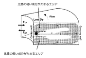
- FIG. 2 shows a cross section of the flow channel of the curved channel 10.
- Solid particles are supposed to gather on the inner circumference side in this secondary flow (Dean vortex), but depending on the balance of the density of solid particles, the flux of the fluid flowing in the channel, the curvature of the channel, etc.
- particles may gather on the outer peripheral side.
- the curved channel 10 may have a processing liquid outlet separated from the inner peripheral side of the flow channel and a concentrated liquid outlet separated from the outer peripheral side of the flow channel.
- the bending channel 10 adjusts the density of the solid particles in the bending channel 10, the flux of the fluid flowing in the flow path, the balance of the curvature of the flow path, and the like to adjust the density difference between the solid particles and the liquid, and gravity. By the hydrodynamic action, the solid particles can be separated from the liquid to be treated.
- a part of the inner wall surface of the flow path of the curved channel 10 is a slip wall surface.
- one of the upper and lower inner wall surfaces of the flow path of the bent channel 10 is a slip surface, and the remaining inner wall surface is a non-slip surface.
- the wall velocity becomes zero on the untreated wall surface due to the fluid frictional resistance. This is called a non-slip surface (see FIG. 3(a)).
- the water-repellent wall surface has the effect of reducing the fluid frictional resistance, so that the wall surface flow velocity does not become zero. This is called a slip surface (see FIG. 3B).
- the lower inner wall surface of the channel of the curved channel 10 is a slip surface, and the remaining three inner wall surfaces (upper inner wall surface and inner wall surfaces on both sides) are non-slip. Is a face.
- the cross section of the flow channel is circular or elliptical
- the lower inner wall surface of the flow channel of the curved channel 10 is a slip surface
- the remaining inner wall surface is a non-slip surface.
- the lower inner wall surface when the cross section of the flow path is circular or elliptic means the lower half of the flow path.
- the lower inner wall surface refers to a surface located on the lower side (gravitational direction) when the solid-liquid separation device 1 is used.
- the return flow to the inner side of the flow channel in the Dean vortex at the lower portion of the flow channel is weakened and the outer lower portion of the flow channel is lower than the conventional curved channel.
- the solid particles are easily collected and the solid-liquid separation accuracy is improved. Therefore, the performance of separating particles having a density close to that of the fluid from the fluid is excellent.
- the wall flow velocity on the slip wall surface of the flow channel of the curved channel 10 should be larger than 0.
- a water-repellent finishing treatment with a fluororesin, a silicone resin, or the like, or the use of a water-repellent material such as a fluororesin or a silicone resin can be mentioned.
- the curved channel 10 is not particularly limited as long as it has a flow path including a wall surface having a curvature.
- the curved channel 10 is, for example, a pipe in which a flow path including a wall surface having a curvature is formed in a spiral shape.
- the cross-sectional shape of the flow channel of the curved channel 10 may be rectangular, circular, elliptical, or the like, and it is desirable that the cross-sectional shape of the flow channel is rectangular in order to form a Dean vortex.
- the curved channel 10 has a flow path including an upper wall surface, a lower wall surface, and a side wall surface having a curvature, and at least a part of the upper wall surface or the lower wall surface is a slip wall surface.
- the curved channel 10 preferably has a predetermined curvature, length, and width determined according to the purpose of separating solid particles.
- the specifications of the curved channel that is most suitable for the separation of solid particles vary depending on the properties of the solid particles (density, particle size, etc.), so it is desirable to determine using flow analysis software.
- Examples of the flow analysis software include “ANSYS Fluent” (ANSYS).
- the solid particles can be separated by adjusting the balance of the density of the solid particles in the curved channel 10, the flux of the fluid flowing in the flow channel, the curvature of the flow channel, and the like.
- the object to be treated in the solid-liquid separation method and the solid-liquid separation apparatus according to the present embodiment is not particularly limited as long as it is a liquid containing solid particles.
- it can be used in solid-liquid separation in coagulation separation treatment, selective control and separation of solid particles in centimeter-micrometer size pipes and channels, and the like.
- the solid-liquid separation method and the solid-liquid separation apparatus according to this embodiment may be used to perform coagulation separation treatment, or to measure water quality in the coagulation separation treatment.
- An example is shown below.
- a water quality measuring device includes the solid-liquid separation device, and a treatment liquid quality measuring unit (treated water quality measuring unit) that measures a liquid quality (water quality) of a treatment liquid (treated water),
- the treated liquid quality measuring means is a means for measuring at least one of turbidity, chromaticity, organic matter concentration, particle size, and particle size distribution.
- the water quality measuring device is, for example, a coagulant addition means for adding a coagulant to the water to be treated, and a separation means for separating the concentrated water containing the flocs formed by adding the coagulant and the treated water.
- a treated water quality measuring means for measuring the water quality of the treated water; and the separating means is the solid-liquid separation device.
- the coagulation-separation device may further include a mixing means for mixing the water to be treated and the coagulant, and a floc forming means for forming flocs in the mixed admixture. You may use the said solid-liquid separation device as a mixing means or a floc formation means.
- a water quality measuring method includes the solid-liquid separation method and a treatment liquid quality measuring step (treatment water quality measuring step) for measuring a liquid quality (water quality) of a treatment liquid (treated water), In the treated liquid quality measuring step (treated water quality measuring step), at least one of turbidity, chromaticity, organic matter concentration, particle size, and particle size distribution is measured.
- the water quality measuring method includes, for example, a flocculating agent addition step of adding a flocculant to the water to be treated, and a separation step of separating concentrated water containing flocs formed by adding the flocculant and treated water.
- the coagulation-separation method may further include a mixing step of mixing the water to be treated and a coagulant, and a floc forming step of forming flocs in the mixed admixture.
- the solid-liquid separation device may be used in the mixing step and the floc forming step.
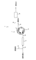
- FIG. 4 An outline of an example of the water quality measuring device according to the present embodiment is shown in FIG. 4, and its configuration will be described.
- the water quality measuring device 3 shown in FIG. 4 is, for example, a coagulant adding pipe 30 as a coagulant adding means for adding a coagulant to the water to be treated, and a line mixer as a mixing means for mixing the coagulant and the water to be treated. 18, the floc forming means for forming flocs in the mixed admixture, and the solid-liquid separation device 1 as the separating means for separating concentrated water containing the formed flocs and treated water, and the water quality of the treated water.
- a treated water quality measuring device 20 is provided as a treated water quality measuring means for measuring the.
- the treated water pipe 22 is connected to the inlet of the line mixer 18.
- the outlet of the line mixer 18 and the mixed liquid inlet of the curved channel 10 are connected by a mixed liquid pipe 24.
- a concentrated water pipe 26 is connected to the concentrated water outlet of the curved channel 10, and a treated water pipe 28 is connected to the treated water outlet.
- a coagulant-added pipe 30 is connected to the treated water pipe 22.
- a treated water quality measuring device 20 is installed in the treated water pipe 28.
- the water to be treated containing suspended substances and the like is sent to the line mixer 18 through the pipe 22 to be treated.
- the coagulant is added to the treated water through the coagulant addition pipe 30 (coagulant addition step), and in the line mixer 18, the coagulant and the treated water are stirred and mixed. (Mixing process).
- the mixed liquid in which the coagulant and the water to be treated are mixed is sent to the curved channel 10 through the mixed liquid pipe 24.
- the admixture was introduced from the admixture inlet of the curved channel 10 into the flow channel of the spiral channel, agitated by the hydrodynamic action in the flow channel, and formed by admixing and aggregating the coagulant and the water to be treated.
- the fine flocs collide with each other and the particle size of the flocs grows (floc forming step).
- As it flows through the flow channel it is separated into treated water on the outer peripheral side of the flow channel and concentrated water on the inner peripheral side of the flow channel, for example, due to the density difference between water and flocs, and gravity and hydrodynamic action. (Separation step).
- the concentrated water is discharged through the concentrated water pipe 26, and the treated water is discharged through the treated water pipe 28 (the above is the aggregation separation step).
- the treated water quality measuring device 20 measures the treated water quality (treated water quality measuring step).
- FIG. 5 uses a tester called a jar tester equipped with multiple stirring blades that can control the number of revolutions, and determines the optimum amount of flocculant to be added for flocculation and solid-liquid separation.
- the evaluation water quality measuring device 100 includes an evaluation mixing tank 102 as an evaluation mixing means, an evaluation floc forming tank 104 as an evaluation floc forming means, and an evaluation solid-liquid separation device 106 as an evaluation separating means.
- a flocculant is added to and mixed with the water to be treated, flocs are formed in the evaluation floc forming tank 104, and sedimentation separation by gravity or filtration is performed in the evaluation solid-liquid separation device 106 by gravity. Solid-liquid separation is performed to separate concentrated water and treated water. The quality of the treated water is measured by the treated water quality measuring device 108.
- the conventional auto jar tester has many parts, poor maintainability, and high cost.
- the jar tester is capable of testing 4 to 6 conditions at the same time.
- the conventional jar test is, for example, 3 minutes for mixing, 10 minutes for floc formation, and 10 minutes for solid-liquid separation. 10 minutes, 10 minutes for measurement of treated water, 33 minutes or more in total.
- a total of 30 minutes or more is required for the jar test. In some cases, a delay occurs, which makes it impossible to follow a rapid change in the water quality of the water to be treated, and the quality of the treated water deteriorates.
- the solid-liquid separation device 1 enables high-speed coagulation separation.
- the water quality measuring device 3 including the solid-liquid separation device 1 as a jar tester or an auto jar tester for performing a test for determining the optimum amount of coagulant added for aggregation, solid-liquid separation, etc.
- the speed can be increased, and the aggregating conditions and the like of the aggregating and separating treatment can be quickly determined based on the water quality of the treated water measured by the treated water quality measuring device 20.
- the jar test can be performed in-line, and the optimum coagulation-separation processing conditions can be continuously determined.
- the mixing (mixing step) of the coagulant and the water to be treated is performed using the line mixer 18, but instead of the line mixer 18, a stirring device having a stirring blade or the like.
- the agitation tank provided with may be used as the mixing means, or the same bending channel 10 as the floc forming means and the separating means or the bending channel different from the floc forming means and the separating means may be used as the mixing means.
- the flock forming means and the separating means are curved channels, but the mixing means, the flock forming means and the separating means may be curved channels. That is, although the floc forming step and the separating step are performed using the bent channel, the mixing step, the flock forming step and the separating step may be performed using the bent channel.
- the time required for the mixing step of mixing the coagulant and the water to be treated is, for example, about 1 second to 60 seconds, preferably about 5 seconds to 30 seconds, and includes the coagulant.
- the time required for the floc formation step of forming flocs in the water to be treated is, for example, about 10 seconds to 10 minutes, preferably about 1 minute to 5 minutes, and the time required for the separation step of separating concentrated water and treated water. Is, for example, about 1 second to 5 minutes, preferably about 1 second to 10 seconds, and the time required for the treated water quality measuring step of measuring the treated water quality is, for example, about 1 second to 30 seconds. Therefore, the time required from the mixing step to the treated water quality measuring step is about 10 seconds to 3 minutes, preferably about 10 seconds to 60 seconds.
- the flocs can be formed and separated by adjusting the balance of the density of particles in the curved channel 10, the flux of the fluid flowing in the flow channel, the curvature of the flow channel, and the like.
- the agent and the water to be treated can be mixed, flocs can be formed and separated.
- flock formation and separation can be performed in a continuous bending channel by asymptotically starting from a small curvature towards the optimum curvature for separation. You may make the cross-sectional area of a flow path asymptotic toward an optimal value.
- the flux is high and agitation is performed, and in a channel whose cross-sectional area is optimal for separation, separation is performed.
- the water quality measuring device 3 in FIG. 4 may be used as it is as a coagulation/separation device, or the water quality measuring device 3 in FIG. 4 excluding the treated water quality measurement device 20 may be used as a coagulation/separation device.
- the flocculation separator is a flocculant addition means for adding a flocculant to the water to be treated, and a separation means for separating concentrated water containing flocs formed by adding the flocculant and treated water.
- the separation means is the solid-liquid separation device.
- the coagulation/separation device may further include a mixing means for mixing the water to be treated and the coagulant, and a floc forming means for forming flocs in the mixed admixture.
- the coagulation separation method includes a coagulant addition step of adding a coagulant to the water to be treated, a separation step of separating the concentrated water containing flocs formed by adding the coagulant and the treated water,
- the solid-liquid separation device (solid-liquid separation method) is used in the separation step.
- the coagulation-separation method may further include a mixing step of mixing the water to be treated and a coagulant, and a floc forming step of forming flocs in the mixed admixture.
- the solid-liquid separation device may be used in the mixing step and the floc forming step.
- At least one of an inorganic coagulant and a polymer coagulant is used as the coagulant.
- inorganic flocculant examples include iron-based inorganic flocculants such as ferric chloride and polyferric sulfate, and aluminum-based inorganic flocculants such as aluminum sulfate and polyaluminum chloride (PAC).
- iron-based inorganic flocculants such as ferric chloride and polyferric sulfate
- aluminum-based inorganic flocculants such as aluminum sulfate and polyaluminum chloride (PAC).
- the amount of the inorganic coagulant added is, for example, in the range of 1 to 100 mg/L.
- the polymer coagulant is not particularly limited, such as a nonionic polymer coagulant, an anionic polymer coagulant or a cationic polymer coagulant, for example, polyacrylamide, sodium polyacrylate, acrylamide Examples thereof include acrylate copolymer, sodium acrylamidopropane sulfonate, chitosan, dimethylaminoethyl methacrylate, dimethylaminoethyl acrylate, polyamidine and the like.
- the polymer flocculants may be used alone or in combination of two or more.
- the amount of the polymer flocculant added is, for example, in the range of 0.1 to 2 mg/L.
- pH may be adjusted as necessary (pH adjusting process).
- the pH adjuster is an acid such as hydrochloric acid or sulfuric acid, or an alkali such as sodium hydroxide.
- the pH may be adjusted within the range of 4 to 11, for example.
- the treated water quality measuring device 20 is not particularly limited as long as it can measure the water quality of the treated water, and is at least one of turbidity, chromaticity, organic matter concentration, particle size, and particle size distribution. It is preferable that it is a device that measures at least one of the particle size and the particle size distribution by image analysis.
- the liquid temperature in the coagulation separation process is not particularly limited and is, for example, in the range of 15 to 35°C. Since the separability changes depending on the viscosity, it is desirable to adjust the liquid temperature so that it is as constant as possible.
- the water to be treated that is the treatment target in the water quality measuring device and the coagulation/separation device is, for example, water containing suspended substances and the like, and examples thereof include river water, industrial water, drainage water, and the like.
- treated water having a suspended substance concentration of 1 to 10 mg/L is removed at a rate of 90% to 99%. be able to.
- the mixing step, the floc formation step, and the separation step may be performed using curved channels.
- the water to be treated is sampled from the inlet water of the coagulation separation treatment apparatus of the actual machine, and the treated water quality of the coagulation separation apparatus
- the flocculation conditions of the actual flocculation/separation processing apparatus may be controlled based on the measurement result of 1.
- the amount of the coagulant added in the actual flocculation/separation treatment device may be controlled based on the quality of the treated water for evaluation measured by the treatment water quality measurement device.
- Example 1 The wall flow velocity of the lower inner wall surface of the curved channel is greater than 0 (the lower inner wall surface is a slip surface), and the wall fluid velocity of the remaining inner wall surface is 0 (the remaining inner wall surface is a non-slip surface)
- Example 1 An experiment was conducted to confirm In Example 1, the lower inner wall surface was a slip surface and the other three inner wall surfaces were non-slip surfaces in the cross-sectional direction of the rectangular flow path.
- Comparative Example 1 all the inner wall surfaces in the cross-sectional direction of the rectangular flow path were non-slip surfaces (wall surface flow velocity was 0). Density of the fluid, 998kg / m 3, the density of the particles is 1005kg / m 3. The degree of separation of particles was 0.95 in Example 1 and ⁇ 0.05 in Comparative Example 1.
- Example 1 it can be seen that the lower inner wall surface of the flow path of the curved channel is a slip surface, so that the flow toward the center is suppressed, and the lower outer wall surface is easily retained in the lower outer portion. This is considered to improve the separability.
- the solid-liquid separation device of the example was excellent in the separation performance from the fluid of particles having a density close to that of the fluid.
- 1 solid-liquid separation device 3 water quality measuring device, 10 curved channel, 12 treated liquid line, 14 outlet line, 16 treated liquid line, 18 line mixer, 20,108 treated water quality measuring device, 22 treated water pipe, 24 admixture Liquid piping, 26 concentrated water piping, 28 treated water piping, 30 coagulant addition piping, 100 evaluation water quality measuring device, 102 evaluation mixing tank, 104 evaluation floc forming tank, 106 evaluation solid-liquid separation device, 108 processed water quality Measuring device, 110 coagulation separation device for evaluation.
Landscapes
- Chemical & Material Sciences (AREA)
- Life Sciences & Earth Sciences (AREA)
- Health & Medical Sciences (AREA)
- Medicinal Chemistry (AREA)
- Engineering & Computer Science (AREA)
- Food Science & Technology (AREA)
- Chemical Kinetics & Catalysis (AREA)
- Physics & Mathematics (AREA)
- Analytical Chemistry (AREA)
- Biochemistry (AREA)
- General Health & Medical Sciences (AREA)
- General Physics & Mathematics (AREA)
- Immunology (AREA)
- Pathology (AREA)
- Separation Of Suspended Particles By Flocculating Agents (AREA)
Abstract
流体に近い密度を有する粒子の流体からの分離性能に優れる固液分離装置および固液分離方法を提供する。固体粒子を含む被処理液から固体粒子を含む濃縮液と処理液とに分離するための分離手段として曲がりチャネル(10)を有し、曲がりチャネル(10)は、曲率を有する壁面を含む流路を有し、流路の内壁面の一部がスリップ壁面である、固液分離装置(1)である。
Description
本発明は、固体と液体を分離する固液分離装置、固液分離方法、およびその固液分離装置または固液分離方法を用いた水質測定装置、水質測定方法に関する。
固体と液体を分離する固液分離装置として、流体から流体と同じ密度を有する中立浮力粒子を分離するシステムであって、遠心力を導入して中立浮力粒子がチャネルの中心からチャネルの渦巻きの中心側の方へずれた管状帯を流体中に形成するように適合された湾曲したチャネル形状を有する渦巻き状チャネルと、管状帯が流れる流体のための第1の出口と、残りの流体のための第2の出口と、を有し、管状帯が渦巻き状チャネル内で遠心力、壁揚力とサフマン慣性揚力、マグヌス力との平衡と、ディーン渦流の発生に基づき非対称的に流れ、流体が、液体であるシステムが知られている(特許文献1参照)。
特許文献1のシステムでは、上記各力の平衡が不安定であったり、ディーン渦流の発達が不十分である場合、粒子の分離性能が著しく低下する。また、特許文献1のシステムは、流体から流体と同じ密度を有する中立浮力粒子を分離するシステムではあるが、流体と異なる密度であるが流体に近い密度を有する粒子の分離性能が十分ではない。
本発明の目的は、流体に近い密度を有する粒子の流体からの分離性能に優れる固液分離装置および固液分離方法、ならびにその固液分離装置または固液分離方法を用いた水質測定装置および水質測定方法を提供することにある。
本発明は、固体粒子を含む被処理液から前記固体粒子を含む濃縮液と処理液とに分離するための分離手段を有する固液分離装置であって、前記分離手段は、曲率を有する壁面を含む流路を有し、前記流路の内壁面の一部がスリップ壁面である、固液分離装置である。
前記固液分離装置において、前記分離手段は、上壁面と下壁面と曲率を有する側壁面とを含む流路を有し、前記上壁面または前記下壁面の少なくとも一部がスリップ壁面であることが好ましい。
前記固液分離装置において、前記スリップ壁面上での壁面流速は、0より大きいことが好ましい。
前記固液分離装置において、前記スリップ壁面は、撥水加工処理が施された壁面、または撥水素材が使用された壁面であることが好ましい。
本発明は、前記固液分離装置と、前記処理液の液質を測定する処理液質測定手段と、を備え、前記処理液質測定手段は、濁度、色度、有機物濃度、粒子径、および粒子径分布のうちの少なくとも1つを測定する手段である、水質測定装置である。
本発明は、固体粒子を含む被処理液から前記固体粒子を含む濃縮液と処理液とに分離する分離工程を含み、前記分離工程は、曲率を有する壁面を含む流路を用いて行い、前記流路の内壁面の一部がスリップ壁面である、固液分離方法である。
前記固液分離方法において、前記分離工程は、上壁面と下壁面と曲率を有する側壁面とを含む流路を用いて行い、前記上壁面または前記下壁面の少なくとも一部がスリップ壁面であることが好ましい。
前記固液分離方法において、前記スリップ壁面上での壁面流速は、0より大きいことが好ましい。
前記固液分離方法において、前記スリップ壁面は、撥水加工処理が施された壁面、または撥水素材が使用された壁面であることが好ましい。
本発明は、前記固液分離方法と、前記処理液の液質を測定する処理液質測定工程と、を含み、前記処理液質測定工程において、濁度、色度、有機物濃度、粒子径、および粒子径分布のうちの少なくとも1つを測定する、水質測定方法である。
本発明では、流体に近い密度を有する粒子の流体からの分離性能に優れる固液分離装置および固液分離方法、ならびにその固液分離装置または固液分離方法を用いた水質測定装置および水質測定方法を提供することができる。
本発明の実施の形態について以下説明する。本実施形態は本発明を実施する一例であって、本発明は本実施形態に限定されるものではない。
本発明の実施形態に係る固液分離装置の一例の概略を図1に示し、その構成について説明する。
本実施形態に係る固液分離装置1は、固体粒子を含む被処理液から固体粒子を含む濃縮液と処理液とに分離するための分離手段として、曲がりチャネル10を有する。曲がりチャネル10は、曲率を有する壁面を含む流路を有し、流路の内壁面の一部がスリップ壁面である。固液分離装置1は、固体粒子が濃縮された濃縮液を曲がりチャネル10から取り出す出口ライン14と、処理液を曲がりチャネル10から取り出す処理液ライン16と、を有してもよい。
図1に示す固液分離装置1において、曲がりチャネル10の被処理液入口には、被処理液ライン12が接続されている。曲がりチャネル10の濃縮液出口には、出口ライン14が接続され、処理液出口には、処理液ライン16が接続されている。
本実施形態に係る固液分離方法および固液分離装置1の動作について説明する。
図1の固液分離装置1において、固体粒子を含む被処理液は、被処理液ライン12を通して、曲がりチャネル10へ送液される。
被処理液は、曲がりチャネル10の被処理液入口から渦巻き状チャネルの流路に導入され、流路を流れていくと、固体粒子と液体との密度差と重力と流体力学的作用とにより、流路の例えば外周側の処理液と流路の例えば内周側の濃縮液とに分離される(分離工程)。濃縮液は、出口ライン14を通して排出され、処理液は、処理液ライン16を通して排出される(分離工程)。
曲がりチャネル10は、被処理液を流入するための被処理液入口と、流体が流れるための例えば矩形状の流路を有する配管が渦巻き状に形成された渦巻き状チャネルと、処理液を排出するための、流路の例えば外周側から分かれた処理液出口と、濃縮液を排出するための、流路の例えば内周側から分かれた濃縮液出口と、を有する。図2に曲がりチャネル10の流路の断面を示すが、固体粒子を含む被処理液が被処理液入口から渦巻き状チャネルに導入されると、矩形状の流路の断面には二次流れ(ディーン渦)が生じる。これは遠心力による外向きの流れと、直進しようとする流れが外壁により強制的に曲げられることによる内向きへの圧力によるものである。
固体粒子はこの二次流れ(ディーン渦)の中では内周側に集まるとされるが、固体粒子の密度、流路中を流れる流体の流束、流路の曲率等のバランスによっては、固体粒子が外周側に集まる場合もある。この場合には、曲がりチャネル10は、流路の内周側から分かれた処理液出口と、流路の外周側から分かれた濃縮液出口と、を有していてもよい。曲がりチャネル10は、曲がりチャネル10における固体粒子の密度、流路中を流れる流体の流束、流路の曲率等のバランスを調整することにより、固体粒子と液体との密度差と、重力と、流体力学的作用とによって、被処理液から固体粒子を分離することができる。
本実施形態に係る固液分離装置1では、曲がりチャネル10の流路の内壁面の一部がスリップ壁面である。例えば、曲がりチャネル10の流路の上下内壁面のうちいずれか一方は、スリップ面であり、残りの内壁面は、ノンスリップ面である。粘性流体を通水した場合、例えば未処理の壁面では流体摩擦抵抗によって、壁面流速は0となる。これをノンスリップ面という(図3(a)参照)。一方、例えば撥水性の壁面では流体摩擦抵抗の軽減効果が得られるため、壁面流速は0とならない。これをスリップ面という(図3(b)参照)。例えば、流路の断面が図2に示すように矩形状の場合、曲がりチャネル10の流路の下内壁面はスリップ面であり、残りの3内壁面(上内壁面および両側内壁面)はノンスリップ面である。例えば、流路の断面が円状や楕円状の場合、曲がりチャネル10の流路の下内壁面はスリップ面であり、残りの内壁面はノンスリップ面である。なお、流路の断面が円状や楕円状の場合の下内壁面とは、流路の下半分のことを指す。また、下内壁面とは、固液分離装置1を使用する際に下側(重力方向)に位置する面のことを言う。
曲がりチャネル10の流路の内壁面の一部がスリップ壁面であることにより、従来の曲がりチャネルに比べて、流路下部のディーン渦流における、流路内側への戻り流れが弱まり、流路外側下部へ固体粒子が集まりやすくなり、固液分離精度が向上する。したがって、流体に近い密度を有する粒子の流体からの分離性能に優れる。
曲がりチャネル10の流路のスリップ壁面上での壁面流速は、0より大きければよい。
流路の内壁面をスリップ壁面とする方法としては、例えば、フッ素樹脂、シリコン系樹脂等による撥水加工処理や、フッ素樹脂、シリコン系樹脂等の撥水素材の使用等が挙げられる。
曲がりチャネル10は、曲率を有する壁面を含む流路を有するものであればよく、特に制限はない。曲がりチャネル10は、例えば、曲率を有する壁面を含む流路を有する配管が渦巻き状に形成されたものである。曲がりチャネル10の流路の断面形状は、矩形状、円状、楕円状等が挙げられ、ディーン渦の形成のためには、流路の断面形状が矩形状であることが望ましい。すなわち、曲がりチャネル10は、上壁面と下壁面と曲率を有する側壁面とを含む流路を有し、上壁面または下壁面の少なくとも一部がスリップ壁面であることが好ましい。
曲がりチャネル10は、固体粒子の分離の目的に応じて決められた所定の曲率、長さ、および幅を有することが好ましい。
固体粒子の分離に最適となる曲がりチャネルの仕様は、固体粒子の性状(密度、粒子径等)によって変化するため、流動解析ソフトを用いて決定することが望ましい。流動解析ソフトとしては、例えば、「ANSYS Fluent」(ANSYS社)等が挙げられる。
上記の通り、曲がりチャネル10における固体粒子の密度、流路中を流れる流体の流束、流路の曲率等のバランスを調整することにより、固体粒子の分離を行うことができる。
本実施形態に係る固液分離方法および固液分離装置における処理対象は、固体粒子を含む液体であればよく、特に制限はない。例えば、凝集分離処理における固液分離、センチメートルからマイクロメートルサイズの配管やチャネルにおける固体粒子の選択的な制御や分離等において用いることができる。
本実施形態に係る固液分離方法および固液分離装置を用いて、凝集分離処理を行ってもよいし、凝集分離処理における水質測定を行ってもよい。以下にその一例を示す。
本発明の実施形態に係る水質測定装置は、上記固液分離装置と、処理液(処理水)の液質(水質)を測定する処理液質測定手段(処理水質測定手段)と、を備え、処理液質測定手段(処理水質測定手段)は、濁度、色度、有機物濃度、粒子径、および粒子径分布のうちの少なくとも1つを測定する手段である。水質測定装置は、例えば、被処理水に凝集剤を添加するための凝集剤添加手段と、凝集剤が添加されて形成されたフロックを含む濃縮水と処理水とに分離するための分離手段と、を備える凝集分離装置と;処理水の水質を測定する処理水質測定手段と;を備え、分離手段が上記固液分離装置である。凝集分離装置は、被処理水と凝集剤とを混和するための混和手段と、混和された混和液中にフロックを形成するためのフロック形成手段と、をさらに備えてもよい。上記固液分離装置を、混和手段や、フロック形成手段として用いてもよい。
本発明の実施形態に係る水質測定方法は、上記固液分離方法と、処理液(処理水)の液質(水質)を測定する処理液質測定工程(処理水質測定工程)と、を含み、処理液質測定工程(処理水質測定工程)において、濁度、色度、有機物濃度、粒子径、および粒子径分布のうちの少なくとも1つを測定する方法である。水質測定方法は、例えば、被処理水に凝集剤を添加する凝集剤添加工程と、凝集剤が添加されて形成されたフロックを含む濃縮水と処理水とに分離する分離工程と、を含む凝集分離方法と;処理水の水質を測定する処理水質測定工程と;を含み、分離工程において上記固液分離装置(上記固液分離方法)を用いる。凝集分離方法は、被処理水と凝集剤とを混和する混和工程と、混和された混和液中にフロックを形成するフロック形成工程と、をさらに含んでもよい。混和工程や、フロック形成工程において、上記固液分離装置を用いてもよい。
本実施形態に係る水質測定装置の一例の概略を図4に示し、その構成について説明する。
図4に示す水質測定装置3は、例えば、被処理水に凝集剤を添加するための凝集剤添加手段として凝集剤添加配管30と、凝集剤と被処理水とを混和する混和手段としてラインミキサ18と、混和された混和液中にフロックを形成するフロック形成手段、および形成されたフロックを含む濃縮水と処理水とに分離する分離手段として、上記固液分離装置1と、処理水の水質を測定する処理水質測定手段として処理水質測定装置20と、を備える。
図4の水質測定装置3において、ラインミキサ18の入口に被処理水配管22が接続されている。ラインミキサ18の出口と曲がりチャネル10の混和液入口とは、混和液配管24により接続されている。曲がりチャネル10の濃縮水出口には、濃縮水配管26が接続され、処理水出口には、処理水配管28が接続されている。被処理水配管22には、凝集剤添加配管30が接続されている。処理水配管28には、処理水質測定装置20が設置されている。
本実施形態に係る水質測定方法、および固液分離装置1を備える水質測定装置3の動作について説明する。
図4の水質測定装置3において、懸濁物質等を含む被処理水は、被処理水配管22を通して、ラインミキサ18へ送液される。ここで、被処理水配管22において、凝集剤添加配管30を通して被処理水に凝集剤が添加され(凝集剤添加工程)、ラインミキサ18において、凝集剤と被処理水とが撹拌されて混和される(混和工程)。凝集剤と被処理水とが混和された混和液は、混和液配管24を通して、曲がりチャネル10へ送液される。
混和液は、曲がりチャネル10の混和液入口から渦巻き状チャネルの流路に導入され、流路における流体力学的作用により撹拌が行われ、凝集剤と被処理水との混和、凝集により形成された微細なフロック同士が衝突して、フロックの粒子径が成長する(フロック形成工程)。流路を流れていくと、水とフロックとの密度差と重力と流体力学的作用とにより、流路の例えば外周側の処理水と流路の例えば内周側の濃縮水とに分離される(分離工程)。濃縮水は、濃縮水配管26を通して排出され、処理水は、処理水配管28を通して排出される(以上が、凝集分離工程)。
次に、処理水配管28において、処理水質測定装置20によって、処理水の水質が測定される(処理水質測定工程)。
図5に、回転数を制御できる複数の撹拌翼を備えるジャーテスタと呼ばれる試験装置を用い、凝集、固液分離に最適な凝集剤の添加量等を決定する、従来のジャーテストによる凝集条件決定方法の一例の概略を示す。評価用水質測定装置100は、評価用混和手段として評価用混和槽102と、評価用フロック形成手段として評価用フロック形成槽104と、評価用分離手段として評価用固液分離装置106と、を備える評価用凝集分離装置110と;処理水質測定手段として処理水質測定装置108と;を備える。例えば、評価用混和槽102において、被処理水に凝集剤が添加されて混和され、評価用フロック形成槽104においてフロックが形成され、評価用固液分離装置106において重力による沈降分離、ろ過等により固液分離が行われ、濃縮水と処理水とに分離される。処理水の水質は、処理水質測定装置108により測定される。
従来のオートジャーテスタは部品点数が多く、メンテナンス性が悪い、高価になるという課題がある。また、ジャーテスタは、同時に4条件~6条件の試験が可能であるが、1回の試験には、従来のジャーテストでは、例えば、混和に3分、フロック形成に10分、固液分離に10分、処理水質の測定に10分、合計33分以上要する。実際の凝集分離処理において、被処理水の処理水質に応じて従来のジャーテストで凝集条件を決める場合、急激な被処理水の水質変動があった場合に、合計30分以上要するジャーテストでは時間遅れが生じてしまい、急激な被処理水の水質変動に追従できず、処理水質が悪化する場合がある。
本実施形態に係る固液分離装置1により、高速で凝集分離を行うことができる。この固液分離装置1を備える水質測定装置3を、例えば、凝集、固液分離に最適な凝集剤の添加量等を決定する試験を行うジャーテスタまたはオートジャーテスタとして用いることにより、ジャーテストの高速化が可能となり、処理水質測定装置20によって測定された処理水の水質に基づいて迅速に凝集分離処理の凝集条件等を決定することができる。そのため、被処理水の水質変動があっても、特に被処理水の急激な水質変動があっても、最適な凝集条件を追従させることができるため、処理水質の悪化が抑制される。ジャーテストをインラインで行うことができ、連続的に最適な凝集分離処理条件を決定することができる。
図4の水質測定装置3において、凝集剤と被処理水との混和(混和工程)は、ラインミキサ18を用いて行われているが、ラインミキサ18の代わりに、撹拌羽根等を有する撹拌装置を備える撹拌槽を混和手段として用いてもよいし、フロック形成手段および分離手段と同じ曲がりチャネル10、またはフロック形成手段および分離手段とは別の曲がりチャネルを混和手段として用いてもよい。
図4の水質測定装置3において、フロック形成手段および分離手段は曲がりチャネルであるが、混和手段、フロック形成手段および分離手段が曲がりチャネルであってもよい。すなわち、フロック形成工程および分離工程を、曲がりチャネルを用いて行うが、混和工程、フロック形成工程および分離工程を、曲がりチャネルを用いて行ってもよい。
図4の水質測定装置3において、凝集剤と被処理水とを混和する混和工程に要する時間は、例えば、1秒~60秒程度、好ましくは5秒~30秒程度であり、凝集剤を含む被処理水中にフロックを形成するフロック形成工程に要する時間は、例えば、10秒~10分程度、好ましくは1分~5分程度であり、濃縮水と処理水とに分離する分離工程に要する時間は、例えば、1秒~5分程度、好ましくは1秒~10秒程度であり、処理水の水質を測定する処理水質測定工程に要する時間は、例えば、1秒~30秒程度である。したがって、混和工程から処理水質測定工程に要する時間は、10秒~3分程度、好ましくは10秒~60秒程度である。
上記の通り、曲がりチャネル10における粒子の密度、流路中を流れる流体の流束、流路の曲率等のバランスを調整することにより、フロックの形成および分離を行うことができ、さらには、凝集剤と被処理水との混和、フロックの形成および分離を行うことができる。例えば、曲がりチャネル10において、分離に最適な曲率に向けて、小さい曲率から漸近させることによってフロックの形成および分離を連続した曲がりチャネルで行うことができる。流路の断面積を最適な値に向けて漸近させてもよい。狭い流路では流束が高く撹拌がなされ、断面積が分離に最適である流路では分離がなされる。
図4の水質測定装置3をそのまま凝集分離装置として用いてもよいし、図4の水質測定装置3において、例えば、処理水質測定装置20を除いたものを凝集分離装置として用いてもよい。例えば、凝集分離装置は、被処理水に凝集剤を添加するための凝集剤添加手段と、凝集剤が添加されて形成されたフロックを含む濃縮水と処理水とに分離するための分離手段と、を備え、分離手段が上記固液分離装置である。凝集分離装置は、被処理水と凝集剤とを混和するための混和手段と、混和された混和液中にフロックを形成するためのフロック形成手段と、をさらに備えてもよい。上記固液分離装置を、混和手段や、フロック形成手段として用いてもよい。また、凝集分離方法は、被処理水に凝集剤を添加する凝集剤添加工程と、凝集剤が添加されて形成されたフロックを含む濃縮水と処理水とに分離する分離工程と、を含み、分離工程において上記固液分離装置(固液分離方法)を用いる。凝集分離方法は、被処理水と凝集剤とを混和する混和工程と、混和された混和液中にフロックを形成するフロック形成工程と、をさらに含んでもよい。混和工程や、フロック形成工程において、上記固液分離装置を用いてもよい。
凝集剤としては、無機凝集剤および高分子凝集剤のうちの少なくとも1つが用いられる。
無機凝集剤としては、例えば、塩化第二鉄、ポリ硫酸第二鉄等の鉄系無機凝集剤、硫酸アルミニウム、ポリ塩化アルミニウム(PAC)等のアルミニウム系無機凝集剤等が挙げられる。
無機凝集剤の添加量は、例えば、1~100mg/Lの範囲である。
高分子凝集剤としては、ノニオン性高分子凝集剤、アニオン性高分子凝集剤またはカチオン性高分子凝集剤等、特に制限されるものではないが、例えば、ポリアクリルアミド、ポリアクリル酸ナトリウム、アクリルアミド・アクリル酸塩共重合体、アクリルアミドプロパンスルフォン酸ナトリウム、キトサン、ジメチルアミノエチルメタクリレート、ジメチルアミノエチルアクリレートおよびポリアミジン等が挙げられる。高分子凝集剤は、1種単独でも、2種以上を組み合わせて用いてもよい。
高分子凝集剤の添加量は、例えば、0.1~2mg/Lの範囲である。
混和工程において、必要に応じて、pH調整を行ってもよい(pH調整工程)。pH調整剤としては、塩酸、硫酸等の酸や、水酸化ナトリウム等のアルカリである。pHは、例えば、4~11の範囲に調整すればよい。
処理水質測定装置20は、処理水の水質を測定することができるものであればよく、特に制限はないが、濁度、色度、有機物濃度、粒子径、および粒子径分布のうちの少なくとも1つを測定する装置であることが好ましく、画像解析によって粒子径および粒子径分布のうちの少なくとも1つを測定する手段であることがより好ましい。
凝集分離処理(混和工程、フロック形成工程、分離工程)における液温度は、特に制限はなく、例えば、15~35℃の範囲である。粘性等によって分離性が変わるため、液温度はできるだけ一定になるように調整することが望ましい。
水質測定装置および凝集分離装置における処理対象である被処理水は、例えば、懸濁物質等を含む水であり、例えば、河川水、工業用水、排水等が挙げられる。
本実施形態に係る凝集分離方法および凝集分離装置、または水質測定方法および水質測定装置により、例えば、懸濁物質濃度1~10mg/Lの被処理水を、90%~99%の割合で除去することができる。
本実施形態に係る凝集分離方法および凝集分離装置、または水質測定方法および水質測定装置において、混和工程、フロック形成工程、分離工程を、それぞれ曲がりチャネルを用いて行ってもよい。
本実施形態に係る凝集分離方法および凝集分離装置、または水質測定方法および水質測定装置において、被処理水が、実機の凝集分離処理装置の入口水からサンプリングしたものであり、凝集分離装置の処理水質の測定結果に基づいて、実機の凝集分離処理装置の凝集条件を制御してもよい。例えば、処理水質測定装置によって測定された評価用処理水の水質に基づいて、実機の凝集分離処理装置において添加される凝集剤の量が制御されればよい。
以下、実施例および比較例を挙げ、本発明をより具体的に詳細に説明するが、本発明は、以下の実施例に限定されるものではない。
<実施例1および比較例1>
曲がりチャネルの流路の下内壁面の壁面流速が0より大きく(下内壁面がスリップ面である)、残りの内壁面の壁面流速が0である(残りの内壁面がノンスリップ面である)効果を確認する実験を行った。実施例1では、矩形状の流路の断面方向において下内壁面をスリップ面、他の3内壁面をノンスリップ面とした。比較例1では、矩形状の流路の断面方向の内壁面全てをノンスリップ面(壁面流速が0)とした。流体の密度は、998kg/m3、粒子の密度は、1005kg/m3である。粒子の分離度は、実施例1が0.95、比較例1が<0.05であった。
曲がりチャネルの流路の下内壁面の壁面流速が0より大きく(下内壁面がスリップ面である)、残りの内壁面の壁面流速が0である(残りの内壁面がノンスリップ面である)効果を確認する実験を行った。実施例1では、矩形状の流路の断面方向において下内壁面をスリップ面、他の3内壁面をノンスリップ面とした。比較例1では、矩形状の流路の断面方向の内壁面全てをノンスリップ面(壁面流速が0)とした。流体の密度は、998kg/m3、粒子の密度は、1005kg/m3である。粒子の分離度は、実施例1が0.95、比較例1が<0.05であった。
実施例1では、曲がりチャネルの流路の下内壁面がスリップ面であることによって、中心方向への流れが抑制され、外側下部に滞留しやすくなっていることがわかる。これによって、分離性が向上したと考えられる。
このように、実施例の固液分離装置は、流体に近い密度を有する粒子の流体からの分離性能に優れていた。
1 固液分離装置、3 水質測定装置、10 曲がりチャネル、12 被処理液ライン、14 出口ライン、16 処理液ライン、18 ラインミキサ、20,108 処理水質測定装置、22 被処理水配管、24 混和液配管、26 濃縮水配管、28 処理水配管、30 凝集剤添加配管、100 評価用水質測定装置、102 評価用混和槽、104 評価用フロック形成槽、106 評価用固液分離装置、108 処理水質測定装置、110 評価用凝集分離装置。
Claims (10)
- 固体粒子を含む被処理液から前記固体粒子を含む濃縮液と処理液とに分離するための分離手段を有する固液分離装置であって、
前記分離手段は、曲率を有する壁面を含む流路を有し、前記流路の内壁面の一部がスリップ壁面であることを特徴とする固液分離装置。 - 請求項1に記載の固液分離装置であって、
前記分離手段は、上壁面と下壁面と曲率を有する側壁面とを含む流路を有し、前記上壁面または前記下壁面の少なくとも一部がスリップ壁面であることを特徴とする固液分離装置。 - 請求項1または2に記載の固液分離装置であって、
前記スリップ壁面上での壁面流速は、0より大きいことを特徴とする固液分離装置。 - 請求項1~3のいずれか1項に記載の固液分離装置であって、
前記スリップ壁面は、撥水加工処理が施された壁面、または撥水素材が使用された壁面であることを特徴とする固液分離装置。 - 請求項1~4のいずれか1項に記載の固液分離装置と、
前記処理液の液質を測定する処理液質測定手段と、
を備え、
前記処理液質測定手段は、濁度、色度、有機物濃度、粒子径、および粒子径分布のうちの少なくとも1つを測定する手段であることを特徴とする水質測定装置。 - 固体粒子を含む被処理液から前記固体粒子を含む濃縮液と処理液とに分離する分離工程を含み、
前記分離工程は、曲率を有する壁面を含む流路を用いて行い、前記流路の内壁面の一部がスリップ壁面であることを特徴とする固液分離方法。 - 請求項6に記載の固液分離方法であって、
前記分離工程は、上壁面と下壁面と曲率を有する側壁面とを含む流路を用いて行い、前記上壁面または前記下壁面の少なくとも一部がスリップ壁面であることを特徴とする固液分離方法。 - 請求項6または7に記載の固液分離方法であって、
前記スリップ壁面上での壁面流速は、0より大きいことを特徴とする固液分離方法。 - 請求項6~8のいずれか1項に記載の固液分離方法であって、
前記スリップ壁面は、撥水加工処理が施された壁面、または撥水素材が使用された壁面であることを特徴とする固液分離方法。 - 請求項6~9のいずれか1項に記載の固液分離方法と、
前記処理液の液質を測定する処理液質測定工程と、
を含み、
前記処理液質測定工程において、濁度、色度、有機物濃度、粒子径、および粒子径分布のうちの少なくとも1つを測定することを特徴とする水質測定方法。
Applications Claiming Priority (2)
| Application Number | Priority Date | Filing Date | Title |
|---|---|---|---|
| JP2018-234211 | 2018-12-14 | ||
| JP2018234211A JP7287622B2 (ja) | 2018-12-14 | 2018-12-14 | 水質測定装置、および水質測定方法 |
Publications (1)
| Publication Number | Publication Date |
|---|---|
| WO2020122157A1 true WO2020122157A1 (ja) | 2020-06-18 |
Family
ID=71077341
Family Applications (1)
| Application Number | Title | Priority Date | Filing Date |
|---|---|---|---|
| PCT/JP2019/048604 Ceased WO2020122157A1 (ja) | 2018-12-14 | 2019-12-12 | 固液分離装置、固液分離方法、水質測定装置、および水質測定方法 |
Country Status (3)
| Country | Link |
|---|---|
| JP (1) | JP7287622B2 (ja) |
| TW (1) | TW202035005A (ja) |
| WO (1) | WO2020122157A1 (ja) |
Families Citing this family (1)
| Publication number | Priority date | Publication date | Assignee | Title |
|---|---|---|---|---|
| KR102934105B1 (ko) * | 2022-12-20 | 2026-03-05 | 한국광기술원 | 공기 중 부유 미생물을 신속하게 검출할 수 있는 검출장치 및 시스템 |
Citations (7)
| Publication number | Priority date | Publication date | Assignee | Title |
|---|---|---|---|---|
| JP2004042012A (ja) * | 2001-10-26 | 2004-02-12 | Nec Corp | 分離装置、分析システム、分離方法および分離装置の製造方法 |
| JP2004202336A (ja) * | 2002-12-25 | 2004-07-22 | Fuji Electric Systems Co Ltd | マイクロチャンネルチップ |
| JP2009128341A (ja) * | 2007-11-28 | 2009-06-11 | Rohm Co Ltd | マイクロチップおよびその製造方法 |
| US20110096327A1 (en) * | 2009-09-24 | 2011-04-28 | University Of Cincinnati | Spiral Microchannel Particle Separators, Straight Microchannel Particle Separators, and Continuous Particle Separator and Detector Systems |
| JP2016526479A (ja) * | 2013-06-14 | 2016-09-05 | パロ・アルト・リサーチ・センター・インコーポレーテッドPalo Alto Research Center Incorporated | 高アスペクト比のチャネルを使用する流体力学的分離 |
| WO2017168054A1 (en) * | 2016-04-01 | 2017-10-05 | Kemira Oyj | A method and system for optimization of coagulation and/or flocculation in a water treatment process |
| WO2019193849A1 (ja) * | 2018-04-05 | 2019-10-10 | オルガノ株式会社 | 凝集分離装置、凝集分離方法、水質測定装置、水質測定方法、凝集分離処理システム、および凝集分離処理方法 |
Family Cites Families (6)
| Publication number | Priority date | Publication date | Assignee | Title |
|---|---|---|---|---|
| JP2538466B2 (ja) * | 1991-11-27 | 1996-09-25 | 川崎重工業株式会社 | 凝集剤の注入制御方法及び装置 |
| US10052571B2 (en) | 2007-11-07 | 2018-08-21 | Palo Alto Research Center Incorporated | Fluidic device and method for separation of neutrally buoyant particles |
| US20100314327A1 (en) | 2009-06-12 | 2010-12-16 | Palo Alto Research Center Incorporated | Platform technology for industrial separations |
| JP5208061B2 (ja) * | 2009-06-29 | 2013-06-12 | 株式会社日立製作所 | 凝集剤注入制御システム |
| US9458489B2 (en) | 2010-03-04 | 2016-10-04 | Massachusetts Institute Of Technology | Microfluidics sorter for cell detection and isolation |
| CN104001349B (zh) | 2014-06-20 | 2015-08-05 | 西南民族大学 | 用于液液两相分离的微通道分离器 |
-
2018
- 2018-12-14 JP JP2018234211A patent/JP7287622B2/ja active Active
-
2019
- 2019-12-12 WO PCT/JP2019/048604 patent/WO2020122157A1/ja not_active Ceased
- 2019-12-13 TW TW108145793A patent/TW202035005A/zh unknown
Patent Citations (7)
| Publication number | Priority date | Publication date | Assignee | Title |
|---|---|---|---|---|
| JP2004042012A (ja) * | 2001-10-26 | 2004-02-12 | Nec Corp | 分離装置、分析システム、分離方法および分離装置の製造方法 |
| JP2004202336A (ja) * | 2002-12-25 | 2004-07-22 | Fuji Electric Systems Co Ltd | マイクロチャンネルチップ |
| JP2009128341A (ja) * | 2007-11-28 | 2009-06-11 | Rohm Co Ltd | マイクロチップおよびその製造方法 |
| US20110096327A1 (en) * | 2009-09-24 | 2011-04-28 | University Of Cincinnati | Spiral Microchannel Particle Separators, Straight Microchannel Particle Separators, and Continuous Particle Separator and Detector Systems |
| JP2016526479A (ja) * | 2013-06-14 | 2016-09-05 | パロ・アルト・リサーチ・センター・インコーポレーテッドPalo Alto Research Center Incorporated | 高アスペクト比のチャネルを使用する流体力学的分離 |
| WO2017168054A1 (en) * | 2016-04-01 | 2017-10-05 | Kemira Oyj | A method and system for optimization of coagulation and/or flocculation in a water treatment process |
| WO2019193849A1 (ja) * | 2018-04-05 | 2019-10-10 | オルガノ株式会社 | 凝集分離装置、凝集分離方法、水質測定装置、水質測定方法、凝集分離処理システム、および凝集分離処理方法 |
Also Published As
| Publication number | Publication date |
|---|---|
| JP7287622B2 (ja) | 2023-06-06 |
| JP2020093230A (ja) | 2020-06-18 |
| TW202035005A (zh) | 2020-10-01 |
Similar Documents
| Publication | Publication Date | Title |
|---|---|---|
| JP7233848B2 (ja) | 凝集分離制御装置、凝集分離制御方法、凝集分離処理システム、および凝集分離処理方法 | |
| US20130153510A1 (en) | Method and system for treating aqueous streams | |
| JP5621254B2 (ja) | 含油廃水の処理方法 | |
| WO2016006419A1 (ja) | 凝集方法および凝集装置 | |
| JP7287622B2 (ja) | 水質測定装置、および水質測定方法 | |
| JP7336790B2 (ja) | 水処理システム及び水処理方法 | |
| JP7083274B2 (ja) | 水処理方法および水処理装置 | |
| JP7056824B2 (ja) | 固液分離装置 | |
| JP7074406B2 (ja) | 薬剤添加量制御装置及び薬剤添加量制御方法 | |
| JPH05168818A (ja) | 清澄化プロセスを監視および(または)制御するための管型クラリファイヤ法 | |
| CN118414315A (zh) | 用于在废水处理中监测生物污泥质量的方法和装置 | |
| JP6993838B2 (ja) | 凝集沈殿装置及び凝集沈殿処理方法 | |
| Bubakova et al. | The influence of velocity gradient on properties and filterability of suspension formed during water treatment | |
| JP2022159603A (ja) | 固液分級装置、固液分級方法、凝集分離性評価装置、凝集分離性評価方法、凝集分離処理システム、および凝集分離処理方法 | |
| JP5210948B2 (ja) | 浄水場の薬品注入制御方法 | |
| JP2022159602A (ja) | 固液分離装置、固液分離方法、水質測定装置、および水質測定方法 | |
| WO2018168021A1 (ja) | 凝集剤注入制御方法、制御装置および水処理システム | |
| KR20080057364A (ko) | 수처리 시스템의 응집제 투입 방법 및 장치 | |
| JP2022159604A (ja) | 凝集分離処理システム、凝集分離処理方法、凝集状態検知装置、および凝集状態検知方法 | |
| JP7119658B2 (ja) | 有機物含有水の処理方法 | |
| Radzi | Removal of oil droplets from oil-in-water mixtures by dissolved air flotation (DAF) | |
| WO2004103521A1 (ja) | 凝集沈殿装置 | |
| Levecq et al. | A new design of flocculation tank: the Turbomix® applied to weighted flocculation | |
| JP6754680B2 (ja) | 加圧浮上分離装置の運転方法および加圧浮上分離装置 | |
| JP2018134625A (ja) | 廃水処理システム |
Legal Events
| Date | Code | Title | Description |
|---|---|---|---|
| 121 | Ep: the epo has been informed by wipo that ep was designated in this application |
Ref document number: 19895167 Country of ref document: EP Kind code of ref document: A1 |
|
| NENP | Non-entry into the national phase |
Ref country code: DE |
|
| 122 | Ep: pct application non-entry in european phase |
Ref document number: 19895167 Country of ref document: EP Kind code of ref document: A1 |