WO2020121919A1 - 無線通信システム、親局装置及び無線通信方法 - Google Patents
無線通信システム、親局装置及び無線通信方法 Download PDFInfo
- Publication number
- WO2020121919A1 WO2020121919A1 PCT/JP2019/047479 JP2019047479W WO2020121919A1 WO 2020121919 A1 WO2020121919 A1 WO 2020121919A1 JP 2019047479 W JP2019047479 W JP 2019047479W WO 2020121919 A1 WO2020121919 A1 WO 2020121919A1
- Authority
- WO
- WIPO (PCT)
- Prior art keywords
- optical
- wavelength
- signal
- phase
- transmission
- Prior art date
- Legal status (The legal status is an assumption and is not a legal conclusion. Google has not performed a legal analysis and makes no representation as to the accuracy of the status listed.)
- Ceased
Links
Images



Classifications
-
- H—ELECTRICITY
- H04—ELECTRIC COMMUNICATION TECHNIQUE
- H04B—TRANSMISSION
- H04B10/00—Transmission systems employing electromagnetic waves other than radio-waves, e.g. infrared, visible or ultraviolet light, or employing corpuscular radiation, e.g. quantum communication
- H04B10/25—Arrangements specific to fibre transmission
- H04B10/2575—Radio-over-fibre, e.g. radio frequency signal modulated onto an optical carrier
- H04B10/25752—Optical arrangements for wireless networks
- H04B10/25753—Distribution optical network, e.g. between a base station and a plurality of remote units
- H04B10/25754—Star network topology
-
- H—ELECTRICITY
- H04—ELECTRIC COMMUNICATION TECHNIQUE
- H04B—TRANSMISSION
- H04B10/00—Transmission systems employing electromagnetic waves other than radio-waves, e.g. infrared, visible or ultraviolet light, or employing corpuscular radiation, e.g. quantum communication
- H04B10/11—Arrangements specific to free-space transmission, i.e. transmission through air or vacuum
-
- H—ELECTRICITY
- H04—ELECTRIC COMMUNICATION TECHNIQUE
- H04B—TRANSMISSION
- H04B10/00—Transmission systems employing electromagnetic waves other than radio-waves, e.g. infrared, visible or ultraviolet light, or employing corpuscular radiation, e.g. quantum communication
- H04B10/25—Arrangements specific to fibre transmission
- H04B10/2507—Arrangements specific to fibre transmission for the reduction or elimination of distortion or dispersion
- H04B10/2513—Arrangements specific to fibre transmission for the reduction or elimination of distortion or dispersion due to chromatic dispersion
-
- H—ELECTRICITY
- H04—ELECTRIC COMMUNICATION TECHNIQUE
- H04B—TRANSMISSION
- H04B10/00—Transmission systems employing electromagnetic waves other than radio-waves, e.g. infrared, visible or ultraviolet light, or employing corpuscular radiation, e.g. quantum communication
- H04B10/25—Arrangements specific to fibre transmission
- H04B10/2575—Radio-over-fibre, e.g. radio frequency signal modulated onto an optical carrier
-
- H—ELECTRICITY
- H04—ELECTRIC COMMUNICATION TECHNIQUE
- H04B—TRANSMISSION
- H04B10/00—Transmission systems employing electromagnetic waves other than radio-waves, e.g. infrared, visible or ultraviolet light, or employing corpuscular radiation, e.g. quantum communication
- H04B10/50—Transmitters
- H04B10/516—Details of coding or modulation
- H04B10/548—Phase or frequency modulation
-
- H—ELECTRICITY
- H04—ELECTRIC COMMUNICATION TECHNIQUE
- H04J—MULTIPLEX COMMUNICATION
- H04J14/00—Optical multiplex systems
- H04J14/02—Wavelength-division multiplex systems
- H04J14/0227—Operation, administration, maintenance or provisioning [OAMP] of WDM networks, e.g. media access, routing or wavelength allocation
- H04J14/0254—Optical medium access
- H04J14/0272—Transmission of OAMP information
-
- H—ELECTRICITY
- H04—ELECTRIC COMMUNICATION TECHNIQUE
- H04J—MULTIPLEX COMMUNICATION
- H04J14/00—Optical multiplex systems
- H04J14/02—Wavelength-division multiplex systems
- H04J14/03—WDM arrangements
- H04J14/0305—WDM arrangements in end terminals
-
- Y—GENERAL TAGGING OF NEW TECHNOLOGICAL DEVELOPMENTS; GENERAL TAGGING OF CROSS-SECTIONAL TECHNOLOGIES SPANNING OVER SEVERAL SECTIONS OF THE IPC; TECHNICAL SUBJECTS COVERED BY FORMER USPC CROSS-REFERENCE ART COLLECTIONS [XRACs] AND DIGESTS
- Y02—TECHNOLOGIES OR APPLICATIONS FOR MITIGATION OR ADAPTATION AGAINST CLIMATE CHANGE
- Y02D—CLIMATE CHANGE MITIGATION TECHNOLOGIES IN INFORMATION AND COMMUNICATION TECHNOLOGIES [ICT], I.E. INFORMATION AND COMMUNICATION TECHNOLOGIES AIMING AT THE REDUCTION OF THEIR OWN ENERGY USE
- Y02D30/00—Reducing energy consumption in communication networks
- Y02D30/70—Reducing energy consumption in communication networks in wireless communication networks
Definitions
- the present invention relates to a wireless communication system, a master station device, and a wireless communication method.
- the millimeter wave band is drawing attention as a frequency band that enables high-speed transmission.
- long-distance transmission is difficult because the millimeter wave band has a large propagation loss.
- RoF Radio over Fiber
- an accommodating station master station
- RF Radio Frequency
- the base station slave station
- One of the solutions is beamforming by an array antenna.
- the phase of the RF signal incident on each antenna element of the array antenna is controlled so that the radio waves emitted from each antenna element interfere with each other. Thereby, the radiation direction of the radio wave is controlled as a whole.
- the phase difference of the RF signal incident on the antenna element is controlled by controlling the wavelength of the optical carrier by utilizing the delay difference between the optical signals of each wavelength due to the wavelength dispersion during the transmission of the optical fiber.
- FIG. 3 is a block diagram of the RoF system 900 to which the technique of Patent Document 1 is applied.
- the multi-wavelength variable light source 911 of the accommodation station 910 outputs a plurality of optical signals.
- the wavelength interval between these optical signals can be changed arbitrarily.
- the optical modulator 912 modulates the optical signal of each wavelength with the transmitted RF signal. As a result, the optical modulator 912 outputs a plurality of optical modulation signals.
- Each optical modulation signal is transmitted through the optical fiber 920.
- a delay difference different for each wavelength occurs in each optical modulation signal due to the influence of chromatic dispersion.
- the optical demultiplexer 931 of the base station 930 splits the plurality of optical modulation signals transmitted through the optical fiber 920 for each wavelength.
- a plurality of O/E (optical/electrical) converters 932-1,..., 932-n respectively convert the branched optical modulation signals of respective wavelengths into electric signals.
- the antenna elements 933-1,..., 933-n radiate the converted electric signal as an RF signal.
- a phase difference also occurs in the RF signal due to a delay difference due to chromatic dispersion during transmission in the optical fiber 920, and directivity can be formed.
- FIG. 4 is a diagram of a wireless system 905 to which the technique of Non-Patent Document 1 is applied.
- the multi-wavelength light source 951 outputs a plurality of optical signals having different wavelengths.
- the optical modulator 952 modulates the optical signal of each wavelength with the transmitted RF signal. As a result, the optical modulator 952 outputs a plurality of optical modulation signals.
- Each optical modulation signal is sent to a PDM (programmable dispersion matrix) 953.
- PDM programmable dispersion matrix
- FIG. 5 is a block diagram showing the configuration of the PDM 953.
- the PDM 953 includes n+1 2 ⁇ 2 optical switches 961-1,..., 961-(n+1) and n dispersion elements 962- whose dispersion values are D 0 , 2D 0 ,..., 2 n-1 D 0 , respectively. , 962-2,..., 962-n.
- the dispersion elements 962-1,..., 962-n are composed of dispersion fibers, grating fibers, or the like.
- the PDM 953 adjusts the dispersion value as a whole by switching the 2 ⁇ 2 optical switches 961-1,..., 961-(n+1).
- Each optical modulation signal input to the PDM 953 has a different delay difference according to the dispersion value adjusted by the PDM 953.
- the optical demultiplexer 954 of the wireless system 905 shown in FIG. 4 branches a plurality of optical modulation signals output from the PDM 953 for each wavelength. Since each wavelength corresponds to each antenna element 956-1,..., 956-n in advance, the optical branching is fixed.
- Each of the plurality of O/E (optical/electrical) converters 955-1,..., 955-n converts the branched optical modulation signal of each wavelength into an electric signal.
- the antenna elements 956-1,..., 956-n radiate the converted electric signal as an RF signal. At this time, a phase difference also occurs in the RF signal due to the delay difference due to the dispersion of the PDM 953, and directivity can be formed.
- Patent Document 1 is a method of making a wavelength variable and dispersion fixed to generate a delay difference in a modulated optical signal
- Non-Patent Document 1 is a method of fixing wavelength and variable dispersion to a modulated optical signal. This is a method of causing a delay difference in
- the technique of Patent Document 1 makes the wavelength variable and the dispersion fixed to generate a delay difference in the modulated optical signal. At this time, it is necessary to greatly adjust the wavelength interval between the optical modulation signals depending on the direction forming the directivity, the fiber length, and the frequency of the RF signal. Therefore, the wavelength band to be used is widened, and the wavelength utilization efficiency may be reduced. In particular, in WDM (Wavelength Division Multiplex)-PON (Passive Optical Network), different wavelengths must be used for each base station. If the technique of Patent Document 1 is applied in such a situation, the wavelength band for beamforming must be set in advance in the WDM-PON, and the wavelength band to be used will be greatly expanded.
- WDM Widelength Division Multiplex
- PON Passive Optical Network
- the wavelength is adjusted to form directivity. Therefore, it is necessary to adjust the wavelength sent to the antenna element of the base station. Therefore, the optical demultiplexer of the base station needs to change the wavelength sent to the antenna element of the base station every time the directivity is formed. Branches also need to be changed dynamically. This means that control of the optical demultiplexer of the base station is necessary.
- Non-Patent Document 1 has a fixed wavelength and a variable dispersion to cause a delay difference in a modulated optical signal. At this time, since the wavelength is fixed, the wavelength utilization efficiency is better than that of Patent Document 1. Further, since the optical branch is fixed, it is not necessary to control the optical demultiplexer. However, it is considered that high accuracy is required for designing and manufacturing a PDM for adjusting dispersion. Therefore, there is a fear that the size and cost of the device may increase.
- Non-Patent Document 1 does not mention application to RoF. Therefore, when applying RoF to Non-Patent Document 1 for long-distance optical fiber transmission, in addition to dispersion adjustment by the PDM, the influence of chromatic dispersion during optical fiber transmission must also be considered.
- the present invention provides a wireless communication system, a master station device, and a wireless communication method that can realize a RoF system that does not require base station control while suppressing deterioration of wavelength utilization efficiency and cost increase.
- the purpose is to
- An embodiment of the present invention is a wireless communication system including a master station device and a slave station device that radiates a transmission signal received by light from the master station device through an optical transmission path from a plurality of antenna elements.
- the master station device an optical signal output unit for outputting an optical signal of a plurality of different wavelengths, and for each wavelength, the phase rotation that the optical signal of the wavelength receives during transmission through the optical transmission line, and the wavelength
- a phase adjustment unit that adjusts the phase of the transmission signal based on the phase in the corresponding antenna element, and the optical signal of the wavelength output by the optical signal output unit for each wavelength, according to the wavelength.
- An optical modulation unit that modulates the phase of the transmission signal adjusted by the phase adjustment unit to generate an optical modulation signal, and the optical transmission line that combines the optical modulation signals for each wavelength generated by the optical modulation unit.
- a light demultiplexing unit for demultiplexing the optical modulation signal transmitted through the optical transmission line by the wavelength, and the wavelength demultiplexed by the optical demultiplexing unit.
- a photoelectric conversion unit that outputs the transmission signal obtained by converting the another optical modulation signal into an electric signal to each of the plurality of antenna elements corresponding to the wavelength.
- the optical signal output unit includes a multi-wavelength light source and an optical demultiplexer that separates the optical signal output by the multi-wavelength light source for each wavelength. Or a plurality of light sources that output optical signals of different wavelengths.
- One embodiment of the present invention is the above-mentioned wireless communication system, wherein the phase rotation that the optical signals of each of the plurality of wavelengths receive during transmission through the optical transmission line is It is obtained from the amount of phase rotation received during transmission through the optical transmission line and the difference between the amounts of phase rotation received by the optical signals of the different wavelengths during transmission through the optical transmission line.
- One embodiment of the present invention is a master station apparatus connected to a slave station apparatus that radiates a transmission signal received by light through an optical transmission path from a plurality of antenna elements, and outputs a plurality of optical signals of different wavelengths.
- An optical signal output unit for outputting, a phase rotation of the optical signal of the wavelength received during transmission through the optical transmission line for each wavelength, and a phase of the transmission signal based on a phase in the antenna element corresponding to the wavelength.
- a phase adjusting unit for adjusting the phase, and for each wavelength, the optical signal of the wavelength output by the optical signal output unit is modulated by the transmission signal whose phase is adjusted by the phase adjusting unit according to the wavelength.
- the master station device includes: an optical modulation unit that generates an optical modulation signal; and an optical combining unit that multiplexes the optical modulation signals for each wavelength generated by the optical modulation unit and outputs the multiplexed signal to the optical transmission path.
- One embodiment of the present invention is executed by a wireless communication system having a master station device and a slave station device that radiates a transmission signal received by light from the master station device via an optical transmission path from a plurality of antenna elements.
- a wireless communication method wherein the master station device outputs an optical signal of outputting optical signals of a plurality of different wavelengths, and a phase in which the optical signal of the wavelength is received during transmission through the optical transmission line for each wavelength.
- a phase adjustment step of adjusting the phase of the transmission signal based on the phase in the antenna element corresponding to the wavelength, for each wavelength, the optical signal of the wavelength output in the optical signal output step An optical modulation step of modulating the phase in the phase adjusting step according to the wavelength by the transmission signal to generate an optical modulation signal, and the wavelength-dependent optical modulation signal generated in the optical modulation step.
- the present invention makes it possible to realize a RoF system that does not require base station control, while suppressing deterioration of wavelength utilization efficiency and cost increase.
- FIG. 4 It is a block diagram which shows the structure of the light control beamforming system by the 1st Embodiment of this invention. It is a block diagram which shows the structure of the light control beamforming system by 2nd Embodiment. It is a block diagram which shows the structure of the RoF system to which a prior art is applied. It is a block diagram which shows the structure of the radio system to which a prior art is applied. 5 is a block diagram showing the configuration of the PDM in FIG. 4. FIG.
- the wireless communication system of this embodiment is used as an RoF system that performs beamforming.
- the accommodating station (master station) device causes optical signals of a plurality of wavelengths to be transmitted through the optical fiber toward the base station (slave station) device to have a phase generated by chromatic dispersion during optical fiber transmission.
- Optical modulation is performed by an RF signal whose rotation is previously compensated.
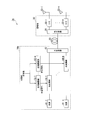
- FIG. 1 is a block diagram showing the configuration of a light control beamforming system 1 according to the first embodiment.
- the light control beamforming system 1 is an example of a wireless communication system.
- the optically controlled beamforming system 1 shown in the figure includes a storage station 10 and a base station 30.
- the accommodation station 10 is a master station device, and the base station 30 is a slave station device.
- the accommodation station 10 and the base station 30 are connected by an optical fiber 20.
- the accommodating station 10 includes a multi-wavelength light source 11, an optical demultiplexer 12, phase adjustment units 13-1,..., 13-n (n is an integer of 2 or more, the same applies below), an optical modulation unit 14-1, , 14-n and a photosynthesizer 15.
- the base station 30 includes an optical demultiplexer 31, O/E (optical/electrical) converters 32-1,..., 32-n and antenna elements 33-1,..., 33-n.
- the multi-wavelength light source 11 generates optical signals of wavelengths ⁇ 1,..., ⁇ n.
- the optical demultiplexer 12 fixedly branches optical signals of wavelengths ⁇ 1,..., ⁇ n.
- the phase adjuster 13-i (i is an integer of 1 or more and n or less, and the same below) is used for the phase of the RF signal in the antenna element 33-i of the base station 30 and the optical modulation of the wavelength ⁇ i during transmission of the optical fiber 20. Phase adjustment is performed on the RF signal based on the phase rotation that the signal is affected by chromatic dispersion.
- the phase adjustment unit 13-i outputs the RF signal #i generated by the phase adjustment.
- the optical modulator 14-i modulates the optical signal of wavelength ⁇ i with the RF signal #i to generate an optical modulation signal.
- the optical combiner 15 inputs the optical modulation signal of the wavelength ⁇ i from the optical modulator 14-i.
- the optical combiner 15 combines the input optical modulation signals of the wavelengths ⁇ 1,..., ⁇ n and outputs the combined optical modulation signals to the optical fiber 20.
- the optical fiber 20 transmits an optical modulation signal.
- the optical demultiplexer 31 of the base station 30 fixedly branches the optical modulation signal transmitted by the optical fiber 20.
- the optical demultiplexer 31 outputs the branched optical modulation signal of the wavelength ⁇ i to the O/E converter 32-i.
- the O/E converter 32-i converts the optical modulation signal of wavelength ⁇ i into an electric signal and outputs it to the antenna element 33-i.
- the antenna element 33-i radiates the electric signal output by the O/E converter 32-i as an RF signal.
- the phase adjustment in the phase adjustment unit 13-i causes a phase difference in the RF signal, so that directivity can be formed.
- the multi-wavelength light source 11 of the accommodation station 10 generates optical signals of n different wavelengths ⁇ 1,..., ⁇ n. Considering one arbitrary wavelength ⁇ i of the n wavelengths ⁇ 1,..., ⁇ n, the wavelength ⁇ i corresponds to the optical modulator 14-i and the antenna element 33-i.
- the optical demultiplexer 12 fixedly branches the optical signals of the wavelengths ⁇ 1,..., ⁇ n generated by the multi-wavelength light source 11 and outputs the optical signals to the optical modulators 14-1,..., 14-n corresponding to the respective wavelengths. To do. Since the optical branch is fixed, it is not necessary to control the optical demultiplexer 12.
- the phase adjuster 13-i takes into account the phase of the input RF signal at the antenna element 33-i of the base station 30 and the phase rotation that the optical modulation signal of wavelength ⁇ i receives during optical fiber transmission due to the influence of chromatic dispersion. Adjust the phase.
- the phase adjustment unit 13-i outputs the phase-adjusted RF signal #i.
- ⁇ i be the amount of phase rotation received as an RF signal when the optical modulation signal of wavelength ⁇ i is transmitted through the optical fiber 20. That is, the phase difference between the RF signal #i input to the optical modulator 14-i and the RF signal that the base station 30 converts and emits the optical modulated signal of wavelength ⁇ i is ⁇ i. Further, the phase of the RF signal radiated by the antenna element 33-i is ⁇ i. At this time, the phase adjusting unit 13-i outputs the RF signal #i in which the phase of the input RF signal is adjusted to ⁇ i ⁇ i. The optical modulator 14-i modulates the optical signal of wavelength ⁇ i with the RF signal #i and outputs the optical modulation signal.
- a signal obtained by modulating an optical signal with an RF signal becomes a DSB (double side band) signal.
- this DSB signal is transmitted through an optical fiber, it is affected by chromatic dispersion, a delay difference is generated between the lower sideband and the upper sideband, and fading occurs. Therefore, the length of the optical fiber that can be transmitted is limited. The higher the frequency of the RF signal, the wider the spacing between the sidebands, and the more pronounced the effect of fading.
- the optical modulator 14-i has a function of performing the fading countermeasure due to the wavelength dispersion, such as converting the optical modulation signal into an SSB (single side band) signal or a two-tone signal. Good.
- the optical combiner 15 combines the optical modulation signals of the wavelengths ⁇ 1,..., ⁇ n output from the optical modulators 14-1,..., 14-n, respectively, and transmits them to one optical fiber 20.
- an optical signal is transmitted through an optical fiber, it is affected by chromatic dispersion and causes a delay difference that differs for each wavelength.
- the optical modulation signal of wavelength ⁇ i is transmitted through the optical fiber 20, the phase is rotated by ⁇ i as an RF signal due to the influence of chromatic dispersion.
- the optical demultiplexer 31 of the base station 30 fixedly branches the optical modulation signals of the wavelengths ⁇ 1,..., ⁇ n transmitted through the optical fiber 20, and outputs them to the antenna elements 33-1,..., 33-n, respectively. To do. Since the optical branch is fixed, it is not necessary to control the optical demultiplexer 31. That is, it is not necessary to control the base station 30.
- the O/E converter 32-i converts the branched optical modulation signal of wavelength ⁇ i into an RF signal.
- the phase adjusting unit 13-i may adjust the phase of the input RF signal to ⁇ i ⁇ i.
- the optical modulation signals of the wavelengths ⁇ 1,..., ⁇ n are transmitted through an optical fiber, they are influenced by chromatic dispersion and are rotated by ⁇ i in phase as an RF signal.
- ⁇ is a difference in the amount of phase rotation received as an RF signal when the optical modulation signals of adjacent wavelengths are transmitted through the optical fiber 20.
- ⁇ is the difference between the phase rotation amount ⁇ j of the wavelength ⁇ j (j is an integer of 1 or more and n ⁇ 1 or less) and the phase rotation amount ⁇ k of the wavelength ⁇ k (j ⁇ k, k is an integer of 2 or more and n or less). Can be obtained by dividing by by (k ⁇ j).
- the accommodating station (master station) of the first embodiment has a multi-wavelength light source capable of generating optical signals of different wavelengths from a single multi-wavelength light source.
- the accommodating station of the present embodiment generates optical signals of different wavelengths by each of the plurality of light sources.
- the difference from the first embodiment will be mainly described.
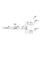
- FIG. 2 is a block diagram showing the configuration of the light control beamforming system 1a according to the second embodiment.
- the light-controlled beamforming system 1a shown in the figure is different from the light-controlled beamforming system 1 shown in FIG. 1 in that the accommodating station 10a is provided instead of the accommodating station 10.
- the accommodation station 10a is different from the accommodation station 10 shown in FIG. 1 in that it includes light sources 41-1,..., 41-n in place of the multi-wavelength light source 11 and the optical demultiplexer 12.
- the light sources 41-1,..., 41-n generate optical signals of different wavelengths.
- the light source 41-i generates an optical signal of wavelength ⁇ i.
- the optical modulator 14-i receives the optical signal of wavelength ⁇ i from the light source 41-i, and the phase adjuster 13-i modulates the RF signal with the RF signal #i obtained by phase adjustment.
- 41-n of the accommodating station 10a generate optical signals of n different wavelengths ⁇ 1,..., ⁇ n, respectively. That is, the light source 41-i generates an optical signal of wavelength ⁇ i. Considering one arbitrary wavelength ⁇ i of the n wavelengths ⁇ 1,..., ⁇ n, the wavelength ⁇ i corresponds to the optical modulator 14-i and the antenna element 33-i.
- the optical modulators 14-1,..., 4-n respectively input optical signals of wavelengths ⁇ 1,.
- the subsequent processing is the same as that of the light control beamforming system 1 of the first embodiment.
- the phase adjustment unit 13-i adjusts the phase of the input RF signal to ⁇ i- ⁇ i and outputs it.
- the amount of phase adjustment is the amount of phase rotation ⁇ i of the RF signal radiated by the antenna element 33-i of the base station 30 and the amount of phase rotation that the optical modulation signal of wavelength ⁇ i receives as an RF signal during transmission of the optical fiber 20 due to the influence of chromatic dispersion.
- the optical modulator 14-i modulates the optical signal having the wavelength ⁇ i with the RF signal #i and outputs the optical modulated signal.
- the optical modulator 14-i has a function of taking measures against fading due to chromatic dispersion, such as converting an optical modulation signal to an SSB signal or a two-tone signal, as in the first embodiment. May be.
- the optical combiner 15 combines the optical modulation signals of the wavelengths ⁇ 1,..., ⁇ n output from the optical modulators 14-1,..., 14-n, respectively, and transmits them to one optical fiber 20.
- an optical modulation signal of wavelength ⁇ i is transmitted through an optical fiber, it is affected by chromatic dispersion, and the phase is rotated by ⁇ i as an RF signal.
- the optical demultiplexer 31 of the base station 30 fixedly branches the optical modulation signals of the wavelengths ⁇ 1,..., ⁇ n transmitted through the optical fiber 20, and outputs them to the antenna elements 33-1,..., 33-n, respectively. To do. Since the optical branch is fixed, it is not necessary to control the optical demultiplexer 31. That is, it is not necessary to control the base station 30.
- the O/E converter 32-i converts the optical modulation signal of wavelength ⁇ i into an RF signal by O/E conversion.
- the optical modulation signal of the wavelength ⁇ i is modulated by the RF signal #i whose phase is adjusted to ⁇ i ⁇ i, and further, the phase is rotated by ⁇ i as an RF signal during transmission through the optical fiber 20.
- the phase of the RF signal obtained by the O/E conversion is ⁇ i.
- the RF signal of this phase ⁇ i is radiated from the antenna element 33-i.
- a phase difference occurs in the RF signals radiated from the antenna elements 33-1,..., 33-n, and directivity can be formed.
- the accommodating station (master station) device of the RoF system transmits each of the plurality of optical signals transmitted by the optical fiber toward the base station (slave station) device by chromatic dispersion during the optical fiber transmission.
- the phase rotation that occurs is optically modulated by an RF signal that has been previously compensated. Therefore, by fixing the wavelength and the dispersion and causing the delay difference in the optical fiber transmission in the optical modulation signal, the deterioration of the wavelength utilization efficiency and the cost increase are suppressed, and the base station control is unnecessary, while the RoF Beamforming in the system can be realized.
- the wireless communication system (for example, the optical control beamforming system 1, 1a) includes the master station device (for example, the accommodating station 10, 10a) and the optical transmission path (for example, the optical fiber 20). It has a slave station device (for example, base station 30) that radiates a transmission signal received by light from the master station device through a plurality of antenna elements (for example, antenna elements 33-1 to 33-n).
- the master station device includes an optical signal output unit, a phase adjustment unit, an optical modulation unit, and an optical combining unit.
- the optical signal output unit outputs optical signals having a plurality of different wavelengths.
- the phase adjusting unit (for example, the phase adjusting units 13-1 to 13-n) is configured to detect, for each wavelength, the phase rotation that an optical signal of one wavelength receives during transmission through the optical transmission line, and the phase in the antenna element corresponding to the wavelength. The phase of the transmission signal is adjusted based on and.
- the optical modulators are transmission signals in which the phase adjusting unit adjusts the phase of the optical signal of one wavelength output by the optical signal output unit for each wavelength. To generate an optical modulation signal.
- the optical combiner (for example, the optical combiner 15) combines the wavelength-dependent optical modulation signals generated by the optical modulator and outputs the multiplexed signals to the optical transmission line.
- the slave station device includes an optical demultiplexing unit (for example, the optical demultiplexer 31) and an optoelectric conversion unit (for example, O/E conversion units 32-1 to 32-n).
- the optical demultiplexing unit demultiplexes the optical modulation signal transmitted through the optical transmission line into wavelengths.
- the opto-electrical conversion unit converts the wavelength-dependent optical modulation signal demultiplexed by the optical demultiplexing unit into an electric signal, and outputs the electric signal to each of a plurality of antenna elements (for example, antenna elements 33-1 to 33-n) corresponding to the wavelength. Output.
- the optical signal output unit includes a multi-wavelength light source (for example, the multi-wavelength light source 11) and an optical demultiplexer (for example, the optical demultiplexer 12) that separates the optical signal output by the multi-wavelength light source for each wavelength. You may have. Further, the optical signal output section may include a plurality of light sources (for example, light sources 41-1 to 41-n) that output optical signals of different wavelengths.
- phase rotation that an optical signal of each of a plurality of wavelengths receives during transmission through the optical transmission line is determined by the amount of phase rotation that the optical signal of any wavelength receives during transmission of the optical transmission line and the optical signals of different wavelengths. May be obtained from the difference in the amount of phase rotation received during transmission through the optical transmission line.
Landscapes
- Engineering & Computer Science (AREA)
- Computer Networks & Wireless Communication (AREA)
- Signal Processing (AREA)
- Physics & Mathematics (AREA)
- Electromagnetism (AREA)
- Optical Communication System (AREA)
Abstract
親局装置は、光伝送路を介して光により受信した送信信号を複数のアンテナ素子から放射する子局装置と接続される。親局装置は、複数の波長の光信号を出力する光信号出力部と、波長別に、光信号が光伝送路を伝送中に受ける位相回転と、当該光信号の波長に対応するアンテナ素子における位相とに基づいて送信信号の位相を調整する位相調整部と、波長別に、光信号出力部が出力した光信号を、当該光信号の波長に応じて位相が調整された送信信号により変調する光変調部と、波長別の光変調信号を合波して光伝送路に出力する光合成部とを備える。子局装置は、光伝送路を伝送した光変調信号を分波する光分波部と、波長別の光変調信号を電気信号に変換して得た送信信号を、波長に対応した複数のアンテナ素子それぞれに出力する光電気変換部とを備える。
Description
本発明は、無線通信システム、親局装置及び無線通信方法に関する。
無線通信サービスにおいて、高速伝送が可能な周波数帯としてミリ波帯が注目されている。しかし、ミリ波帯は伝搬損失が大きいため、長距離伝送が困難であるという問題がある。
この問題の解決策の1つとして、RoF(Radio over Fiber)システムが知られている。RoFシステムでは、収容局(親局)が、伝送したいRF(Radio Frequency:無線周波数)信号により光キャリアを強度変調し、その変調信号を光ファイバで伝送する。基地局(子局)は、光ファイバを介して受信した光信号をRF信号に戻し、そのRF信号をアンテナから電波として放射する。このようなRoFシステムを利用することにより、ミリ波帯RF信号の長距離伝送が可能となる。
しかしながら、ミリ波帯にRoFシステムを適用したとしても、今度は基地局のカバーエリア拡大が課題となる。その解決策の1つがアレーアンテナによるビームフォーミングである。アレーアンテナによるビームフォーミングでは、アレーアンテナの各アンテナ素子に入射するRF信号の位相を制御し、各アンテナ素子から放射される電波を互いに干渉させる。これにより、全体として電波の放射方向を制御する。
RoFシステムにおけるビームフォーミングとして、光ファイバ伝送時の波長分散によって各波長の光信号間に遅延差が生じることを利用して、光キャリアの波長を制御することでアンテナ素子に入射するRF信号の位相を制御する技術が知られている(例えば、特許文献1参照)。
図3は、特許文献1の技術を適用した示したRoFシステム900のブロック図である。収容局910の多波長可変光源911は、複数の光信号を出力する。これら光信号間の波長間隔は、任意に変更可能である。光変調器912は、伝送するRF信号により各波長の光信号を変調する。これにより、光変調器912は、複数の光変調信号を出力する。各光変調信号は光ファイバ920内を伝送する。その際に、各光変調信号には、波長分散の影響により、波長毎に異なる遅延差が生じる。基地局930の光分波器931は、光ファイバ920内を伝送した複数の光変調信号を波長毎に分岐する。複数のO/E(光/電気)変換器932-1、…、932-nはそれぞれ、分岐された各波長の光変調信号を電気信号に変換する。アンテナ素子933-1、…、933-nは、変換後の電気信号をRF信号として放射する。この際、光ファイバ920内伝送時の波長分散による遅延差のためRF信号にも位相差が生じ、指向性を形成することができる。
また、RoFシステムに限らず、光信号を用いてアレーアンテナのビームフォーミングを行う手法がある。その一つとして、波長の制御を行わず、各アンテナ素子に固定波長を割り振っておき、各波長の光信号に対して、波長分散や経路差を利用して遅延差を生じさせる技術が知られている(例えば、非特許文献1参照)。
図4は、非特許文献1の技術を適用した無線システム905の図である。多波長光源951は、複数の異なる波長の光信号を出力する。光変調器952は、伝送するRF信号により各波長の光信号を変調する。これにより、光変調器952は、複数の光変調信号を出力する。各光変調信号は、PDM(programmable dispersion matrix)953に送られる。
図5は、PDM953の構成を示すブロック図である。PDM953は、n+1個の2×2光スイッチ961-1、…、961-(n+1)と、分散値がそれぞれD0、2D0、…、2n-1D0のn個の分散要素962-1、962-2、…、962-nとから構成される。分散要素962-1、…、962-nは、分散ファイバやグレーティングファイバなどにより構成される。PDM953は、2×2光スイッチ961-1、…、961-(n+1)を切り替えることで、全体としての分散値を調整する。PDM953に入力された各光変調信号には、PDM953により調整された分散値に従った異なる遅延差が生じる。
図4に示す無線システム905の光分波器954は、PDM953から出力された複数の光変調信号を波長毎に分岐する。各波長は、各アンテナ素子956-1、…、956-nにあらかじめ対応しているため、光分岐は固定的である。複数のO/E(光/電気)変換器955-1、…、955-nはそれぞれ、分岐された各波長の光変調信号を電気信号に変換する。アンテナ素子956-1、…、956-nは、変換後の電気信号をRF信号として放射する。この際、PDM953の分散による遅延差のためRF信号にも位相差が生じ、指向性を形成することができる。
以上を整理すると、特許文献1は、波長を可変とし、分散を固定として変調光信号に遅延差を生じさせる手法であり、非特許文献1は、波長を固定とし、分散を可変として変調光信号に遅延差を生じさせる手法である。
Dennis T. K. Tong,Ming C. Wu,"A Novel Multiwavelength Optically Controlled Phased Array Antenna with a Programmable Dispersion Matrix",IEEE Photonics Technology Letters,1996年6月,VOL.8,NO.6,p.812-814
上述のように、特許文献1の技術は、波長を可変とし、分散を固定として変調光信号に遅延差を生じさせる。このとき、指向性を形成する方向やファイバ長、RF信号の周波数によっては、光変調信号間の波長間隔を大きく調整する必要がある。そのため、利用する波長帯が広くなってしまい、波長利用効率の低下が考えられる。特に、WDM(Wavelength Division Multiplex)-PON(Passive Optical Network)では、各基地局に異なる波長を使用しなければならない。このような状況で、特許文献1の技術を適用すると、WDM-PONにさらにビームフォーミングのための波長帯をあらかじめ設定しておかなければならなくなり、利用する波長帯は大幅に拡大してしまう。
また、特許文献1の技術では、指向性形成のために波長を調整する。従って、基地局のアンテナ素子に送る波長も調整する必要がある。そのため、基地局の光分波器は、指向性形成の度に、基地局のアンテナ素子に送る波長を変更する必要があり、指向性を動的に変更する際にはさらに光分波器の分岐も動的に変更する必要がある。これは、基地局の光分波器の制御が必要であることを意味する。
RoFシステムを適用する利点の一つは、RF信号の長距離伝送以外に、収容局に機能を集約することで基地局を簡易化できることである。しかし、特許文献1の技術では、基地局の光分波器の制御が必要となり、基地局の簡易化に限界がある。
一方、非特許文献1の技術は、波長を固定とし、分散を可変として変調光信号に遅延差を生じさせる。このとき、波長が固定であるため、波長利用効率は特許文献1よりも良い。また、光分岐は固定的であるため、光分波器を制御する必要がない。しかし、分散を調整するためのPDMの設計・製作には、高い精度が必要になると考えられる。従って、装置の大型化・高コスト化の恐れがある。
また、非特許文献1には、RoFへの適用に関する言及はない。そのため、非特許文献1にRoFを適用して長距離光ファイバ伝送する場合には、PDMによる分散調整以外に、光ファイバ伝送時の波長分散の影響も考慮しなければならない。
上記事情に鑑み、本発明は、波長利用効率の悪化や高コスト化をおさえつつ、基地局制御が不要なRoFシステムを実現することができる無線通信システム、親局装置及び無線通信方法を提供することを目的としている。
本発明の一実施形態は、親局装置と、光伝送路を介して前記親局装置から光により受信した送信信号を複数のアンテナ素子から放射する子局装置とを有する無線通信システムであって、前記親局装置は、複数の異なる波長の光信号を出力する光信号出力部と、前記波長別に、前記波長の前記光信号が前記光伝送路を伝送中に受ける位相回転と、当該波長に対応する前記アンテナ素子における位相とに基づいて前記送信信号の位相を調整する位相調整部と、前記波長別に、前記光信号出力部が出力した前記波長の前記光信号を、当該波長に応じて前記位相調整部が位相を調整した前記送信信号により変調して光変調信号を生成する光変調部と、前記光変調部が生成した前記波長別の前記光変調信号を合波して前記光伝送路に出力する光合成部とを備え、前記子局装置は、前記光伝送路を伝送した前記光変調信号を前記波長により分波する光分波部と、前記光分波部が分波した前記波長別の前記光変調信号を電気信号に変換して得た前記送信信号を、前記波長に対応した複数の前記アンテナ素子それぞれに出力する光電気変換部とを備える、無線通信システムである。
本発明の一実施形態は、上述の無線通信システムであって、前記光信号出力部は、多波長光源及び前記多波長光源が出力した光信号を前記波長ごとに分離する光分波器とを有する、又は、それぞれ異なる前記波長の光信号を出力する複数の光源を有する。
本発明の一実施形態は、上述の無線通信システムであって、複数の前記波長それぞれの前記光信号が前記光伝送路を伝送中に受ける前記位相回転は、いずれかの前記波長の光信号が前記光伝送路を伝送中に受ける位相回転の量と、異なる前記波長それぞれの光信号が前記光伝送路を伝送中に受ける前記位相回転の量の差分とから得られる。
本発明の一実施形態は、光伝送路を介して光により受信した送信信号を複数のアンテナ素子から放射する子局装置と接続される親局装置であって、複数の異なる波長の光信号を出力する光信号出力部と、前記波長別に、前記波長の前記光信号が前記光伝送路を伝送中に受ける位相回転と、当該波長に対応する前記アンテナ素子における位相とに基づいて前記送信信号の位相を調整する位相調整部と、前記波長別に、前記光信号出力部が出力した前記波長の前記光信号を、当該波長に応じて前記位相調整部が位相を調整した前記送信信号により変調して光変調信号を生成する光変調部と、前記光変調部が生成した前記波長別の前記光変調信号を合波して前記光伝送路に出力する光合成部と、を備える親局装置である。
本発明の一実施形態は、親局装置と、光伝送路を介して前記親局装置から光により受信した送信信号を複数のアンテナ素子から放射する子局装置とを有する無線通信システムが実行する無線通信方法であって、前記親局装置が、複数の異なる波長の光信号を出力する光信号出力ステップと、前記波長別に、前記波長の前記光信号が前記光伝送路を伝送中に受ける位相回転と、当該波長に対応する前記アンテナ素子における位相とに基づいて前記送信信号の位相を調整する位相調整ステップと、前記波長別に、前記光信号出力ステップにおいて出力された前記波長の前記光信号を、当該波長に応じて前記位相調整ステップにおいて位相を調整した前記送信信号により変調して光変調信号を生成する光変調ステップと、前記光変調ステップにおいて生成された前記波長別の前記光変調信号を合波して前記光伝送路に出力する光合成ステップと、前記子局装置が、前記光伝送路を伝送した前記光変調信号を前記波長により分波する光分波ステップと、前記光分波ステップにおいて分波された前記波長別の前記光変調信号を電気信号に変換して得た前記送信信号を、前記波長に対応した複数の前記アンテナ素子それぞれに出力する光電気変換ステップと、を有する無線通信方法である。
本発明により、波長利用効率の悪化や高コスト化をおさえつつ、基地局制御が不要なRoFシステムを実現することが可能となる。
以下、図面を参照しながら本発明の実施形態を詳細に説明する。本実施形態の無線通信システムは、ビームフォーミングを行うRoFシステムとして用いられる。本実施形態の無線通信システムにおいて、収容局(親局)装置は、基地局(子局)装置に向けて光ファイバ伝送する複数の波長それぞれの光信号を、光ファイバ伝送時に波長分散で生じる位相回転を予め補償したRF信号により光変調する。これにより、波長利用効率の悪化や高コスト化をおさえつつ、基地局制御が不要なビームフォーミング型RoFシステムを実現することができる。以下に詳細な実施形態を説明する。
<第1の実施形態>
図1は、第1の実施形態による光制御ビームフォーミングシステム1の構成を示すブロック図である。光制御ビームフォーミングシステム1は、無線通信システムの一例である。同図に示す光制御ビームフォーミングシステム1は、収容局10と、基地局30とを有する。収容局10は親局装置であり、基地局30は子局装置である。収容局10及び基地局30は、光ファイバ20により接続される。
図1は、第1の実施形態による光制御ビームフォーミングシステム1の構成を示すブロック図である。光制御ビームフォーミングシステム1は、無線通信システムの一例である。同図に示す光制御ビームフォーミングシステム1は、収容局10と、基地局30とを有する。収容局10は親局装置であり、基地局30は子局装置である。収容局10及び基地局30は、光ファイバ20により接続される。
収容局10は、多波長光源11と、光分波器12と、位相調整部13-1、…、13-n(nは2以上の整数、以下同じ)と、光変調部14-1、…、14-nと、光合成器15とを備える。基地局30は、光分波器31と、O/E(光/電気)変換器32-1、…、32-nと、アンテナ素子33-1、…、33-nとを備える。
多波長光源11は、波長λ1、…、λnの光信号を生成する。光分波器12は、波長λ1、…、λnの光信号を固定的に分岐する。位相調整部13-i(iは1以上n以下の整数、以下同じ)は、RF信号に対し、基地局30のアンテナ素子33-iにおける位相と、光ファイバ20の伝送時に波長λiの光変調信号が波長分散の影響で受ける位相回転とに基づいて、RF信号に位相調整を行う。位相調整部13-iは、位相調整により生成されたRF信号#iを出力する。光変調部14-iは、波長λiの光信号をRF信号#iにより変調して光変調信号を生成する。光合成器15は、光変調部14-iから波長λiの光変調信号を入力する。光合成器15は、入力した波長λ1、…、λnそれぞれの光変調信号を合成し、合成した光変調信号を光ファイバ20に出力する。光ファイバ20は、光変調信号を伝送する。
基地局30の光分波器31は、光ファイバ20が伝送した光変調信号を固定的に分岐する。光分波器31は、分岐した波長λiの光変調信号をO/E変換器32-iに出力する。O/E変換器32-iは、波長λiの光変調信号を電気信号に変換し、アンテナ素子33-iに出力する。アンテナ素子33-iは、O/E変換器32-iが出力した電気信号をRF信号として放射する。このとき、位相調整部13-iにおける位相調整により、RF信号に位相差が生じ、指向性を形成することができる。
光制御ビームフォーミングシステム1の動作の詳細について説明する。
収容局10の多波長光源11は、n個の相異なる波長λ1、…、λnの光信号を生成する。n個の波長λ1、…、λnのうち、任意の1つの波長λiについて考えると、波長λiは、光変調部14-i及びアンテナ素子33-iに対応している。光分波器12は、多波長光源11が生成した波長λ1、…、λnの光信号を固定的に分岐し、各波長に応じた光変調部14-1、…、14-nそれぞれに出力する。光分岐は固定的なため、光分波器12の制御は必要ない。
収容局10の多波長光源11は、n個の相異なる波長λ1、…、λnの光信号を生成する。n個の波長λ1、…、λnのうち、任意の1つの波長λiについて考えると、波長λiは、光変調部14-i及びアンテナ素子33-iに対応している。光分波器12は、多波長光源11が生成した波長λ1、…、λnの光信号を固定的に分岐し、各波長に応じた光変調部14-1、…、14-nそれぞれに出力する。光分岐は固定的なため、光分波器12の制御は必要ない。
位相調整部13-iは、入力されるRF信号に対し、基地局30のアンテナ素子33-iにおける位相と、光ファイバ伝送時に波長λiの光変調信号が波長分散の影響で受ける位相回転をふまえて、位相調整を行う。位相調整部13-iは、位相調整されたRF信号#iを出力する。
波長λiの光変調信号が光ファイバ20を伝送するとき、波長分散の影響を受けて位相回転する。波長λiの光変調信号が光ファイバ20を伝送するときにRF信号として受ける位相回転量をφiとする。つまり、光変調部14-iに入力されるRF信号#iと、基地局30が波長λiの光変調信号を変換して放射するRF信号との位相差をφiとする。
また、アンテナ素子33-iが放射するRF信号の位相をθiとする。このとき、位相調整部13-iは、入力されたRF信号の位相をθi-φiに調整したRF信号#iを出力する。光変調部14-iは、波長λiの光信号をRF信号#iにより変調し、光変調信号を出力する。
また、アンテナ素子33-iが放射するRF信号の位相をθiとする。このとき、位相調整部13-iは、入力されたRF信号の位相をθi-φiに調整したRF信号#iを出力する。光変調部14-iは、波長λiの光信号をRF信号#iにより変調し、光変調信号を出力する。
一般に、光信号をRF信号で変調した信号はDSB(double side band)信号となる。
このDSB信号を光ファイバ伝送すると、波長分散の影響を受け、下側波帯と上側波帯との間に遅延差が生じ、フェージングが発生する。そのため、伝送可能な光ファイバ長が制限されてしまう。RF信号の周波数が高くなるほど、側波帯間の間隔が広くなるため、フェージングの影響が顕著になる。この波長分散によるフェージングを回避するため、光変調部14-iは、光変調信号をSSB(single side band)信号や2トーン信号にするなど、波長分散によるフェージング対策を行う機能を有していてもよい。
このDSB信号を光ファイバ伝送すると、波長分散の影響を受け、下側波帯と上側波帯との間に遅延差が生じ、フェージングが発生する。そのため、伝送可能な光ファイバ長が制限されてしまう。RF信号の周波数が高くなるほど、側波帯間の間隔が広くなるため、フェージングの影響が顕著になる。この波長分散によるフェージングを回避するため、光変調部14-iは、光変調信号をSSB(single side band)信号や2トーン信号にするなど、波長分散によるフェージング対策を行う機能を有していてもよい。
光合成器15は、光変調部14-1、…、14-nそれぞれが出力した波長λ1、…、λnの光変調信号を合成し、1本の光ファイバ20に伝送する。光信号が光ファイバ伝送されるとき、波長分散の影響を受け、波長毎に異なる遅延差を生じる。前述のとおり、波長λiの光変調信号が光ファイバ20中を伝送するとき、波長分散の影響を受けてRF信号としてφiだけ位相回転する。
基地局30の光分波器31は、光ファイバ20中を伝送した波長λ1、…、λnの光変調信号を固定的に分岐し、それぞれをアンテナ素子33-1、…、33-nに出力する。
光分岐は固定的なため、光分波器31の制御は必要ない。つまり、基地局30を制御する必要がない。
光分岐は固定的なため、光分波器31の制御は必要ない。つまり、基地局30を制御する必要がない。
O/E変換器32-iは、分岐された波長λiの光変調信号をRF信号に変換する。波長λiの光変調信号は、位相がθi-φiに調整されたRF信号#iにより変調されており、さらに光ファイバ20の伝送時にRF信号としてφiだけ位相回転した。そのため、波長λiの光変調信号をO/E変換して得られたRF信号の位相は、θi-φi+φi=θiとなる。よって、位相θiのRF信号が、アンテナ素子33-iから放射される。このとき、各アンテナ素子33-1、…、33-nから放射されるRF信号に位相差が生じ、指向性を形成することができる。
つまり、アンテナ素子33-iで放射するRF信号の位相をθiとしたい場合、位相調整部13-iは、入力されたRF信号の位相をθi-φiに調整すればよい。
<第1の実施形態の変形例>
第1の実施形態の多波長光源11が生成するn個の相異なる波長λ1、…、λnの間隔が十分小さい場合、各波長λ1、…、λnに対する光ファイバ20の分散値は等しいとみなせる。このとき、波長λ1、…、λnの間隔を等しくすると、波長λ1、…、λnの光変調信号が光ファイバ20を伝送する時に波長分散によって受ける位相回転の間隔も等しくなる。よって、位相調整部13-1、…、13-nにおける位相調整を簡易化できる。
第1の実施形態の多波長光源11が生成するn個の相異なる波長λ1、…、λnの間隔が十分小さい場合、各波長λ1、…、λnに対する光ファイバ20の分散値は等しいとみなせる。このとき、波長λ1、…、λnの間隔を等しくすると、波長λ1、…、λnの光変調信号が光ファイバ20を伝送する時に波長分散によって受ける位相回転の間隔も等しくなる。よって、位相調整部13-1、…、13-nにおける位相調整を簡易化できる。
多波長光源11が生成する光信号の波長λ1、…、λnの波長間隔が等しい場合、λi=λ1+(i-1)Δλと表せる。この波長λ1、…、λnの光変調信号が光ファイバ伝送されるとき、波長分散の影響を受け、RF信号としてφi位相回転する。ここで、波長λ1、…、λnの波長間隔は等しく、かつ分散値も等しいため、位相回転量も等間隔となる。つまり、φi=φ1+(i-1)Δφとなる。位相調整部13-iは、入力されたRF信号の位相をθi-φi=θi-{φ1+(i-1)Δφ}に調整すればよい。
上記のような計算により、各波長λ1、…、λnの光変調信号について、RF信号としての位相回転量φ1、…、φnをそれぞれ算出するのではなく、φ1とΔφのみを算出してからそれらの代数演算を行い、位相調整量を求めることもできる。なお、Δφは、隣接する波長の光変調信号それぞれが光ファイバ20を伝送する際にRF信号として受ける相回転量の差分である。例えば、Δφは、波長λj(jは1以上n-1以下の整数)の位相回転量φjと、波長λk(j<k、kは2以上n以下の整数)の位相回転量φkとの差分を(k-j)により除算することにより求めることができる。また、φ1に限らず、いずれかの波長λmの位相回転量φm(mは1以上n以下の整数)を用い、φi=φm+(i-m)Δφを算出してもよい。
<第2の実施形態>
第1の実施形態の収容局(親局)では、1台の多波長光源により異なる波長の光信号を生成可能な多波長光源を有していた。本実施形態の収容局は、複数のそれぞれ光源それぞれにより、異なる波長の光信号を生成する。以下では、第1の実施形態との差分を中心に説明する。
第1の実施形態の収容局(親局)では、1台の多波長光源により異なる波長の光信号を生成可能な多波長光源を有していた。本実施形態の収容局は、複数のそれぞれ光源それぞれにより、異なる波長の光信号を生成する。以下では、第1の実施形態との差分を中心に説明する。
図2は、第2の実施形態による光制御ビームフォーミングシステム1aの構成を示すブロック図である。同図において、図1に示す第1の実施形態による光制御ビームフォーミングシステム1と同一の部分には同一の符号を付している。同図に示す光制御ビームフォーミングシステム1aが、図1に示す光制御ビームフォーミングシステム1と異なる点は、収容局10に代えて収容局10aを備える点である。収容局10aが、図1に示す収容局10と異なる点は、多波長光源11及び光分波器12に代えて、光源41-1、…、41-nを備える点である。
光源41-1、…、41-nは、それぞれ相異なる波長の光信号を生成する。光源41-iは、波長λiの光信号を生成する。光変調部14-iは、光源41-iから波長λiの光信号を入力し、位相調整部13-iがRF信号を位相調整して得られたRF信号#iにより変調する。
光制御ビームフォーミングシステム1aの動作の詳細について説明する。
収容局10aの光源41-1、…、41-nはそれぞれ、n個の相異なる波長λ1、…、λnの光信号を生成する。すなわち、光源41-iは、波長λiの光信号を生成する。
n個の波長λ1、…、λnのうち、任意の1つの波長λiについて考えると、波長λiは、光変調部14-i及びアンテナ素子33-iに対応している。光変調部14-1、…、4-nはそれぞれ、波長λ1、…、λnの光信号を入力する。以下の処理は、第1の実施形態の光制御ビームフォーミングシステム1と同様である。
収容局10aの光源41-1、…、41-nはそれぞれ、n個の相異なる波長λ1、…、λnの光信号を生成する。すなわち、光源41-iは、波長λiの光信号を生成する。
n個の波長λ1、…、λnのうち、任意の1つの波長λiについて考えると、波長λiは、光変調部14-i及びアンテナ素子33-iに対応している。光変調部14-1、…、4-nはそれぞれ、波長λ1、…、λnの光信号を入力する。以下の処理は、第1の実施形態の光制御ビームフォーミングシステム1と同様である。
すなわち、位相調整部13-iは、入力されたRF信号の位相をθi-φiに調整し、出力する。この位相調整量は、基地局30のアンテナ素子33-iが放射するRF信号の位相θiと、光ファイバ20の伝送時に波長λiの光変調信号がRF信号として波長分散の影響で受ける位相回転量φiとに基づく。光変調部14-iは、波長λiの光信号をRF信号#iで変調し、光変調信号を出力する。波長分散によるフェージングを回避するため、光変調部14-iは、第1の実施形態と同様に、光変調信号をSSB信号や2トーン信号にするなど波長分散によるフェージング対策を行う機能を有していてもよい。光合成器15は、光変調部14-1、…、14-nそれぞれが出力した波長λ1、…、λnの光変調信号を合成し、1本の光ファイバ20に伝送する。波長λiの光変調信号が光ファイバ中を伝送されるとき、波長分散の影響を受け、RF信号としてφiだけ位相回転する。
基地局30の光分波器31は、光ファイバ20中を伝送した波長λ1、…、λnの光変調信号を固定的に分岐し、それぞれをアンテナ素子33-1、…、33-nに出力する。
光分岐は固定的なため、光分波器31の制御は必要ない。つまり、基地局30を制御する必要がない。O/E変換器32-iは、O/E変換により、波長λiの光変調信号をRF信号に変換する。波長λiの光変調信号は、位相がθi-φiに調整されたRF信号#iにより変調されており、さらに光ファイバ20の伝送時にRF信号としてφiだけ位相回転した。そのため、O/E変換により得られたRF信号の位相はθiとなる。この位相θiのRF信号は、アンテナ素子33-iから放射される。このとき、各アンテナ素子33-1、…、33-nから放射されるRF信号に位相差が生じ、指向性を形成することができる。
光分岐は固定的なため、光分波器31の制御は必要ない。つまり、基地局30を制御する必要がない。O/E変換器32-iは、O/E変換により、波長λiの光変調信号をRF信号に変換する。波長λiの光変調信号は、位相がθi-φiに調整されたRF信号#iにより変調されており、さらに光ファイバ20の伝送時にRF信号としてφiだけ位相回転した。そのため、O/E変換により得られたRF信号の位相はθiとなる。この位相θiのRF信号は、アンテナ素子33-iから放射される。このとき、各アンテナ素子33-1、…、33-nから放射されるRF信号に位相差が生じ、指向性を形成することができる。
<第2の実施形態の変形例>
第2の実施形態の光源41-1、…、41-nにより生成されるn個の相異なる波長λ1、…、λnの間隔が十分小さい場合、各波長λ1、…、λnに対する光ファイバ20の分散値は等しいとみなせる。つまり、λi=λ1+(i-1)Δλと表せる。このとき、波長λ1、…、λnの光変調信号が光ファイバ20を伝送する時に波長分散によって受ける位相回転の間隔も等しくなる。よって、第1の実施形態と同様に、位相調整部13-1、…、13-nにおける位相調整を簡易化できる。
第2の実施形態の光源41-1、…、41-nにより生成されるn個の相異なる波長λ1、…、λnの間隔が十分小さい場合、各波長λ1、…、λnに対する光ファイバ20の分散値は等しいとみなせる。つまり、λi=λ1+(i-1)Δλと表せる。このとき、波長λ1、…、λnの光変調信号が光ファイバ20を伝送する時に波長分散によって受ける位相回転の間隔も等しくなる。よって、第1の実施形態と同様に、位相調整部13-1、…、13-nにおける位相調整を簡易化できる。
すなわち、波長λiの光変調信号は、光ファイバ20中を伝送するとき、波長分散の影響を受け、RF信号としてφi位相回転する。波長λ1、…、λnの波長間隔が等しく、かつ分散値も等しいため、各波長間の位相回転量も等間隔となる。つまり、φi=φ1+(i―1)Δφとなる。よって、各波長λ1、…、λnの光変調信号について、RF信号としての位相回転量φ1、…、φnをそれぞれ算出するのではなく、φ1とΔφのみを算出してからそれらの代数演算を行い、位相調整量を求めることもできる。
以上説明した実施形態によれば、RoFシステムの収容局(親局)装置は、基地局(子局)装置に向けて光ファイバ伝送する複数の光信号の各々を、光ファイバ伝送時に波長分散で生じる位相回転を予め補償したRF信号により光変調する。よって、波長および分散を固定とした上で、光変調信号に光ファイバ伝送における遅延差を生じさせることにより、波長利用効率の悪化や高コスト化をおさえつつ、基地局制御を不要としながら、RoFシステムにおけるビームフォーミングを実現することができる。
上述した実施形態によれば、無線通信システム(例えば、光制御ビームフォーミングシステム1、1a)は、親局装置(例えば、収容局10、10a)と、光伝送路(例えば、光ファイバ20)を介して親局装置から光により受信した送信信号を複数のアンテナ素子(例えば、アンテナ素子33-1~33-n)から放射する子局装置(例えば、基地局30)とを有する。
親局装置は、光信号出力部と、位相調整部と、光変調部と、光合成部とを備える。光信号出力部は、複数の異なる波長の光信号を出力する。位相調整部(例えば、位相調整部13-1~13-n)は、波長別に、一の波長の光信号が光伝送路を伝送中に受ける位相回転と、当該波長に対応するアンテナ素子における位相とに基づいて送信信号の位相を調整する。光変調部(光変調部14-1~14-n)は、波長別に、光信号出力部が出力した一の波長の光信号を、当該波長に応じて位相調整部が位相を調整した送信信号により変調して光変調信号を生成する。光合成部(例えば、光合成器15)は、光変調部が生成した波長別の光変調信号を合波して光伝送路に出力する。
子局装置は、光分波部(例えば、光分波器31)と、光電気変換部(例えば、O/E変換部32-1~32-n)とを備える。光分波部は、光伝送路を伝送した光変調信号を波長により分波する。光電気変換部は、光分波部が分波した波長別の光変調信号を電気信号に変換し、波長に対応した複数のアンテナ素子(例えば、アンテナ素子33-1~33-n)それぞれに出力する。
なお、光信号出力部は、多波長光源(例えば、多波長光源11)と、多波長光源が出力した光信号を波長ごとに分離する光分波器(例えば、光分波器12)とを有してもよい。
また、光信号出力部は、それぞれ異なる波長の光信号を出力する複数の光源(例えば、光源41-1~41-n)を有してもよい。
また、光信号出力部は、それぞれ異なる波長の光信号を出力する複数の光源(例えば、光源41-1~41-n)を有してもよい。
また、複数の波長それぞれの光信号が光伝送路を伝送中に受ける位相回転を、いずれかの波長の光信号が光伝送路を伝送中に受ける位相回転の量と、異なる波長それぞれの光信号が光伝送路を伝送中に受ける位相回転の量の差分とから得てもよい。
以上、この発明の実施形態について図面を参照して詳述してきたが、具体的な構成はこの実施形態に限られるものではなく、この発明の要旨を逸脱しない範囲の設計等も含まれる。
1、1a…光制御ビームフォーミングシステム, 10、10a…収容局, 11…多波長光源, 12…光分波器, 13-1~13-n…位相調整部, 14-1~14-n…光変調部, 15…光合成器, 20…光ファイバ, 30…基地局, 31…光分波器, 32-1~32-n…O/E変換器, 33-1~33-n…アンテナ素子, 41-1~41-n…光源
Claims (5)
- 親局装置と、光伝送路を介して前記親局装置から光により受信した送信信号を複数のアンテナ素子から放射する子局装置とを有する無線通信システムであって、
前記親局装置は、
複数の異なる波長の光信号を出力する光信号出力部と、
前記波長別に、前記波長の前記光信号が前記光伝送路を伝送中に受ける位相回転と、当該波長に対応する前記アンテナ素子における位相とに基づいて前記送信信号の位相を調整する位相調整部と、
前記波長別に、前記光信号出力部が出力した前記波長の前記光信号を、当該波長に応じて前記位相調整部が位相を調整した前記送信信号により変調して光変調信号を生成する光変調部と、
前記光変調部が生成した前記波長別の前記光変調信号を合波して前記光伝送路に出力する光合成部とを備え、
前記子局装置は、
前記光伝送路を伝送した前記光変調信号を前記波長により分波する光分波部と、
前記光分波部が分波した前記波長別の前記光変調信号を電気信号に変換して得た前記送信信号を、前記波長に対応した複数の前記アンテナ素子それぞれに出力する光電気変換部とを備える、
無線通信システム。 - 前記光信号出力部は、多波長光源及び前記多波長光源が出力した光信号を前記波長ごとに分離する光分波器とを有する、又は、それぞれ異なる前記波長の光信号を出力する複数の光源を有する、
請求項1に記載の無線通信システム。 - 複数の前記波長それぞれの前記光信号が前記光伝送路を伝送中に受ける前記位相回転は、いずれかの前記波長の光信号が前記光伝送路を伝送中に受ける位相回転の量と、異なる前記波長それぞれの光信号が前記光伝送路を伝送中に受ける前記位相回転の量の差分とから得られる、
請求項1又は請求項2に記載の無線通信システム。 - 光伝送路を介して光により受信した送信信号を複数のアンテナ素子から放射する子局装置と接続される親局装置であって、
複数の異なる波長の光信号を出力する光信号出力部と、
前記波長別に、前記波長の前記光信号が前記光伝送路を伝送中に受ける位相回転と、当該波長に対応する前記アンテナ素子における位相とに基づいて前記送信信号の位相を調整する位相調整部と、
前記波長別に、前記光信号出力部が出力した前記波長の前記光信号を、当該波長に応じて前記位相調整部が位相を調整した前記送信信号により変調して光変調信号を生成する光変調部と、
前記光変調部が生成した前記波長別の前記光変調信号を合波して前記光伝送路に出力する光合成部と、
を備える親局装置。 - 親局装置と、光伝送路を介して前記親局装置から光により受信した送信信号を複数のアンテナ素子から放射する子局装置とを有する無線通信システムが実行する無線通信方法であって、
前記親局装置が、
複数の異なる波長の光信号を出力する光信号出力ステップと、
前記波長別に、前記波長の前記光信号が前記光伝送路を伝送中に受ける位相回転と、当該波長に対応する前記アンテナ素子における位相とに基づいて前記送信信号の位相を調整する位相調整ステップと、
前記波長別に、前記光信号出力ステップにおいて出力された前記波長の前記光信号を、当該波長に応じて前記位相調整ステップにおいて位相を調整した前記送信信号により変調して光変調信号を生成する光変調ステップと、
前記光変調ステップにおいて生成された前記波長別の前記光変調信号を合波して前記光伝送路に出力する光合成ステップと、
前記子局装置が、
前記光伝送路を伝送した前記光変調信号を前記波長により分波する光分波ステップと、
前記光分波ステップにおいて分波された前記波長別の前記光変調信号を電気信号に変換して得た前記送信信号を、前記波長に対応した複数の前記アンテナ素子それぞれに出力する光電気変換ステップと、
を有する無線通信方法。
Priority Applications (1)
| Application Number | Priority Date | Filing Date | Title |
|---|---|---|---|
| US17/311,665 US11405124B2 (en) | 2018-12-10 | 2019-12-04 | Wireless communication system, parent station apparatus and wireless communication method |
Applications Claiming Priority (2)
| Application Number | Priority Date | Filing Date | Title |
|---|---|---|---|
| JP2018-231144 | 2018-12-10 | ||
| JP2018231144A JP7193716B2 (ja) | 2018-12-10 | 2018-12-10 | 無線通信システム、親局装置及び無線通信方法 |
Publications (1)
| Publication Number | Publication Date |
|---|---|
| WO2020121919A1 true WO2020121919A1 (ja) | 2020-06-18 |
Family
ID=71075366
Family Applications (1)
| Application Number | Title | Priority Date | Filing Date |
|---|---|---|---|
| PCT/JP2019/047479 Ceased WO2020121919A1 (ja) | 2018-12-10 | 2019-12-04 | 無線通信システム、親局装置及び無線通信方法 |
Country Status (3)
| Country | Link |
|---|---|
| US (1) | US11405124B2 (ja) |
| JP (1) | JP7193716B2 (ja) |
| WO (1) | WO2020121919A1 (ja) |
Cited By (5)
| Publication number | Priority date | Publication date | Assignee | Title |
|---|---|---|---|---|
| CN112911428A (zh) * | 2021-01-29 | 2021-06-04 | 烽火通信科技股份有限公司 | 基于多波长路径的快速性能优化方法、装置及电子设备 |
| WO2022172413A1 (ja) * | 2021-02-12 | 2022-08-18 | 日本電信電話株式会社 | 無線通信システム及び無線通信方法 |
| JPWO2022269792A1 (ja) * | 2021-06-23 | 2022-12-29 | ||
| WO2023242932A1 (ja) * | 2022-06-13 | 2023-12-21 | 日本電信電話株式会社 | 送信指向性制御装置及び送信指向性制御方法 |
| JPWO2023242931A1 (ja) * | 2022-06-13 | 2023-12-21 |
Families Citing this family (5)
| Publication number | Priority date | Publication date | Assignee | Title |
|---|---|---|---|---|
| CN113853755B (zh) * | 2019-07-31 | 2022-12-30 | 华为技术有限公司 | 一种多波长光源以及光芯片 |
| WO2022037787A1 (en) * | 2020-08-20 | 2022-02-24 | Telefonaktiebolaget Lm Ericsson (Publ) | Generating a common and stable radio frequency (rf) carrier for a plurality of distributed units |
| JP7502680B2 (ja) * | 2020-08-31 | 2024-06-19 | 日本電信電話株式会社 | 無線通信方法、基地局装置、及び無線通信システム |
| JP2023012257A (ja) * | 2021-07-13 | 2023-01-25 | 日本電信電話株式会社 | 無線通信方法 |
| US11916595B1 (en) * | 2023-08-28 | 2024-02-27 | The Jalali Family Trust Dated December 30, 2006. | Wavelength-multiplexed subranging electro-optic modulator (SEOM) for high dynamic range applications |
Citations (2)
| Publication number | Priority date | Publication date | Assignee | Title |
|---|---|---|---|---|
| JPH10145286A (ja) * | 1996-11-13 | 1998-05-29 | Sumitomo Electric Ind Ltd | 移動体無線通信システム |
| JP2014096637A (ja) * | 2012-11-07 | 2014-05-22 | Kddi Corp | Rf信号光伝送システム |
Family Cites Families (6)
| Publication number | Priority date | Publication date | Assignee | Title |
|---|---|---|---|---|
| US20020012495A1 (en) * | 2000-06-29 | 2002-01-31 | Hiroyuki Sasai | Optical transmission system for radio access and high frequency optical transmitter |
| US7155127B2 (en) * | 2001-08-15 | 2006-12-26 | Nippon Telegraph And Telephone Corporation | Optical communication system, optical communication unit, and optical transceiving package |
| JP4246724B2 (ja) | 2005-08-31 | 2009-04-02 | 日本電信電話株式会社 | ビームフォーミング型rofシステム |
| EP3130090B1 (en) * | 2014-04-10 | 2018-01-03 | Telefonaktiebolaget LM Ericsson (publ) | Radio-over-fibre transmission in communications networks |
| WO2016092705A1 (ja) * | 2014-12-12 | 2016-06-16 | 三菱電機株式会社 | レーザレーダ装置 |
| US10868572B2 (en) * | 2017-11-14 | 2020-12-15 | Cable Television Laboratories, Inc | Systems and methods for delta-sigma digitization |
-
2018
- 2018-12-10 JP JP2018231144A patent/JP7193716B2/ja active Active
-
2019
- 2019-12-04 WO PCT/JP2019/047479 patent/WO2020121919A1/ja not_active Ceased
- 2019-12-04 US US17/311,665 patent/US11405124B2/en active Active
Patent Citations (2)
| Publication number | Priority date | Publication date | Assignee | Title |
|---|---|---|---|---|
| JPH10145286A (ja) * | 1996-11-13 | 1998-05-29 | Sumitomo Electric Ind Ltd | 移動体無線通信システム |
| JP2014096637A (ja) * | 2012-11-07 | 2014-05-22 | Kddi Corp | Rf信号光伝送システム |
Cited By (14)
| Publication number | Priority date | Publication date | Assignee | Title |
|---|---|---|---|---|
| CN112911428A (zh) * | 2021-01-29 | 2021-06-04 | 烽火通信科技股份有限公司 | 基于多波长路径的快速性能优化方法、装置及电子设备 |
| JP7557150B2 (ja) | 2021-02-12 | 2024-09-27 | 日本電信電話株式会社 | 無線通信システム及び無線通信方法 |
| WO2022172413A1 (ja) * | 2021-02-12 | 2022-08-18 | 日本電信電話株式会社 | 無線通信システム及び無線通信方法 |
| JPWO2022172413A1 (ja) * | 2021-02-12 | 2022-08-18 | ||
| US12556278B2 (en) | 2021-02-12 | 2026-02-17 | Ntt, Inc. | Wireless communication system and wireless communication method |
| JPWO2022269792A1 (ja) * | 2021-06-23 | 2022-12-29 | ||
| JP7689274B2 (ja) | 2021-06-23 | 2025-06-06 | 日本電信電話株式会社 | 無線通信方法 |
| WO2022269792A1 (ja) * | 2021-06-23 | 2022-12-29 | 日本電信電話株式会社 | 無線通信方法 |
| JPWO2023242931A1 (ja) * | 2022-06-13 | 2023-12-21 | ||
| WO2023242931A1 (ja) * | 2022-06-13 | 2023-12-21 | 日本電信電話株式会社 | 送信指向性制御装置及び送信指向性制御方法 |
| JPWO2023242932A1 (ja) * | 2022-06-13 | 2023-12-21 | ||
| WO2023242932A1 (ja) * | 2022-06-13 | 2023-12-21 | 日本電信電話株式会社 | 送信指向性制御装置及び送信指向性制御方法 |
| JP7701670B2 (ja) | 2022-06-13 | 2025-07-02 | 日本電信電話株式会社 | 送信指向性制御装置及び送信指向性制御方法 |
| JP7701669B2 (ja) | 2022-06-13 | 2025-07-02 | 日本電信電話株式会社 | 送信指向性制御装置及び送信指向性制御方法 |
Also Published As
| Publication number | Publication date |
|---|---|
| JP2020096238A (ja) | 2020-06-18 |
| JP7193716B2 (ja) | 2022-12-21 |
| US11405124B2 (en) | 2022-08-02 |
| US20220109518A1 (en) | 2022-04-07 |
Similar Documents
| Publication | Publication Date | Title |
|---|---|---|
| JP7193716B2 (ja) | 無線通信システム、親局装置及び無線通信方法 | |
| JP7111971B2 (ja) | 無線通信システム、収容局装置及び無線通信方法 | |
| JP7328578B2 (ja) | 無線送信システム、無線受信システム、基地局装置、及び無線通信システム、並びに無線送信方法、及び無線受信方法 | |
| JP4246724B2 (ja) | ビームフォーミング型rofシステム | |
| US11936429B2 (en) | Wireless transmitting system, wireless receiving system, base station apparatus, wireless communication system, wireless transmitting method, and wireless receiving method | |
| JP4632444B2 (ja) | 光制御アレイアンテナ装置 | |
| JP7684597B2 (ja) | 無線通信方法及び無線通信システム | |
| KR101025384B1 (ko) | 고주파 광전송 시스템, 장치 및 방법 | |
| JP7227536B2 (ja) | 無線通信システム、収容局装置及び無線通信方法 | |
| JP2023012257A (ja) | 無線通信方法 | |
| JP7684598B2 (ja) | 無線通信方法及び無線通信システム | |
| US20240267122A1 (en) | Wireless communication method | |
| JP7179234B2 (ja) | 光制御型アレイアンテナ装置 | |
| JP6513046B2 (ja) | 無線送信装置 | |
| WO2025017811A1 (ja) | 送信指向性制御装置、及び送信指向性制御方法 | |
| KR102041714B1 (ko) | 파장 분할 다중화기, 파장분할 다중화 송신기, 파장 분할 다중화 방법 및 파장 분할 다중화 송신 방법 | |
| JP2024044029A (ja) | 光送受信器、これを用いた光送受信装置、及び光源波長制御方法 | |
| WO2025154199A1 (ja) | 張出局、無線システム及び通信方法 | |
| WO2021100070A1 (ja) | 光変調器、及び光送信器 | |
| JP2010103614A (ja) | 光通信システム、光送信器および光送信方法 |
Legal Events
| Date | Code | Title | Description |
|---|---|---|---|
| 121 | Ep: the epo has been informed by wipo that ep was designated in this application |
Ref document number: 19894481 Country of ref document: EP Kind code of ref document: A1 |
|
| NENP | Non-entry into the national phase |
Ref country code: DE |
|
| 122 | Ep: pct application non-entry in european phase |
Ref document number: 19894481 Country of ref document: EP Kind code of ref document: A1 |