WO2020121839A1 - 通信制御装置 - Google Patents
通信制御装置 Download PDFInfo
- Publication number
- WO2020121839A1 WO2020121839A1 PCT/JP2019/046723 JP2019046723W WO2020121839A1 WO 2020121839 A1 WO2020121839 A1 WO 2020121839A1 JP 2019046723 W JP2019046723 W JP 2019046723W WO 2020121839 A1 WO2020121839 A1 WO 2020121839A1
- Authority
- WO
- WIPO (PCT)
- Prior art keywords
- reception
- data
- control
- communication
- unit
- Prior art date
- Legal status (The legal status is an assumption and is not a legal conclusion. Google has not performed a legal analysis and makes no representation as to the accuracy of the status listed.)
- Ceased
Links
Images






Classifications
-
- H—ELECTRICITY
- H04—ELECTRIC COMMUNICATION TECHNIQUE
- H04L—TRANSMISSION OF DIGITAL INFORMATION, e.g. TELEGRAPHIC COMMUNICATION
- H04L69/00—Network arrangements, protocols or services independent of the application payload and not provided for in the other groups of this subclass
- H04L69/40—Network arrangements, protocols or services independent of the application payload and not provided for in the other groups of this subclass for recovering from a failure of a protocol instance or entity, e.g. service redundancy protocols, protocol state redundancy or protocol service redirection
-
- H—ELECTRICITY
- H04—ELECTRIC COMMUNICATION TECHNIQUE
- H04L—TRANSMISSION OF DIGITAL INFORMATION, e.g. TELEGRAPHIC COMMUNICATION
- H04L12/00—Data switching networks
- H04L12/28—Data switching networks characterised by path configuration, e.g. LAN [Local Area Networks] or WAN [Wide Area Networks]
- H04L12/40—Bus networks
- H04L12/40169—Flexible bus arrangements
- H04L12/40176—Flexible bus arrangements involving redundancy
- H04L12/40182—Flexible bus arrangements involving redundancy by using a plurality of communication lines
-
- H—ELECTRICITY
- H04—ELECTRIC COMMUNICATION TECHNIQUE
- H04L—TRANSMISSION OF DIGITAL INFORMATION, e.g. TELEGRAPHIC COMMUNICATION
- H04L12/00—Data switching networks
- H04L12/28—Data switching networks characterised by path configuration, e.g. LAN [Local Area Networks] or WAN [Wide Area Networks]
- H04L12/40—Bus networks
- H04L2012/40267—Bus for use in transportation systems
- H04L2012/40273—Bus for use in transportation systems the transportation system being a vehicle
-
- H—ELECTRICITY
- H04—ELECTRIC COMMUNICATION TECHNIQUE
- H04L—TRANSMISSION OF DIGITAL INFORMATION, e.g. TELEGRAPHIC COMMUNICATION
- H04L67/00—Network arrangements or protocols for supporting network services or applications
- H04L67/01—Protocols
- H04L67/12—Protocols specially adapted for proprietary or special-purpose networking environments, e.g. medical networks, sensor networks, networks in vehicles or remote metering networks
Definitions
- the present invention relates to a communication control device, and more particularly, to a communication control device provided with a communication system in which a plurality of microcomputers are combined to perform predetermined control processing and the microcomputers (arithmetic control devices) are redundantly connected to each other.
- a vehicle control device In a level 2 or higher self-driving vehicle that simultaneously controls vertical (acceleration/deceleration) and lateral (steering) movements of the vehicle, a vehicle control device called an automatic driving ECU plays a central role in vehicle control.
- the autonomous driving ECU has (1) sensing for acquiring data on the own vehicle and the surrounding environment, (2) situation recognition for integrating and analyzing acquired sensor data and map information, and (3) safe driving based on the recognition result. Real-time execution of complicated various information processing including large-scale data, including an action plan for generating a trajectory and (4) actuator control for reflecting the action plan in the motion of the vehicle.
- the connection between multiple functional modules may cause a new bottleneck. That is, since the entire control processing is executed as a software pipeline by a plurality of microcomputers, intermediate data of the processing needs to be transferred in real time (for example, on the order of 10 milliseconds) between the microcomputers that are the main constituent devices of the module. The exchange of various intermediate data may cause a bottleneck.
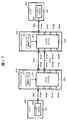
- FIG. 17 shows an example of an inter-microcomputer communication system in which route redundancy is made by a conventional method.
- the microcomputer 900 incorporates an Ethernet adapter 901 that processes an Ethernet protocol, and performs Ethernet communication with the outside of the microcomputer via a connection port 902 to the outside of the microcomputer and an Ethernet cable 903.
- an Ethernet switch 910 is added to the outside of each microcomputer 900, and an Ethernet cable 903 is provided to the plurality of switch connection ports 914 (914a) provided in the Ethernet switch 910. To 914h).
- the Ethernet switch 910 has a control table 911 that holds control information regarding frame transfer rules between the switch connection ports 914, and controls the operation of the switch matrix 913 via the switch matrix control interface 912. As a result, frame transfer is executed between the designated switch connection ports 914.
- An object of the present invention is to provide a communication control device capable of ensuring real-time communication and reducing the load factor of the arithmetic and control unit.
- FIG. 3 is a block diagram showing a detailed configuration of a transmission unit with delay 100.
- FIG. 4 is a block diagram showing a detailed configuration of a masked receiving unit 120.
- FIG. 4 is a table showing the relationship between the information held in the reception state holding register 137 and the operation of the reception mask control unit 136 based on the information.
- 3 is a block diagram showing a detailed configuration of an operation mode control unit 140.
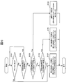
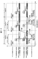
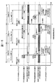
- FIG. 7 is a flowchart showing an operation mode determination flow of operation mode determination unit 150. 6 is a timing chart showing an operation mode determination mechanism of the operation mode control unit 140 based on the occurrence of underflow in the timer 152.
- the operation of the second microcomputer 20 based on the operation mode control method over the control cycle according to the vehicle control device 1 according to the second embodiment of the present invention will be described.
- the operation of the second microcomputer 20 based on the operation mode control method over the control cycle according to the vehicle control device 1 according to the second embodiment of the present invention will be described.
- the operation of the second microcomputer 20 based on the operation mode control method over the control cycle according to the vehicle control device 1 according to the second embodiment of the present invention will be described.
- the operation of the second microcomputer 20 based on the operation mode control method over the control cycle according to the vehicle control device 1 according to the second embodiment of the present invention will be described.
- the communication between the microcomputers with route redundancy by the conventional method is shown.
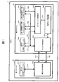
- FIG. 1 shows the configuration of a vehicle control device 1 (communication control device) according to a first embodiment of the present invention.
- the vehicle control device 1 (ECU) includes a first microcomputer 10 (first arithmetic and control unit) and a second microcomputer 20 (second control unit) that respectively execute a part of a predetermined control process imposed on the device. Arithmetic and control unit).
- the vehicle control device 1 is described as having two microcomputers 10 and 20 in FIG. 1, but the vehicle control device 1 may have more than two microcomputers. It goes without saying that it is good. Even when one vehicle control device includes more than two microcomputers, the configuration of the two microcomputers therein can be configured according to the following description.
- the connection between the first microcomputer 10 and the second microcomputer 20 is configured in the form of redundant connection by the first communication means 101 (hereinafter also referred to as TP1) and the second communication means 102 (hereinafter also referred to as TP2). It Although not particularly limited, in order to simplify the description, the data communication direction between the microcomputers will be limited to the first microcomputer 10 (transmission side) to the second microcomputer 20 (reception side).
- the first communication unit 101 and the second communication unit 102 may have common standards/specifications, or some or all of them may be different.
- the first communication unit 101 is a high-speed interface such as PCIe and the second communication unit 102 is a low-speed interface such as CAN or SPI, but the present invention is not limited to this.
- the first communication means 101 is an interface used to transfer all control data (hereinafter also referred to as “normal time data” or “first data”) necessary for executing a predetermined control process. Further, the second communication unit 102 has control data (hereinafter referred to as “control data” necessary for degeneration processing executed when a communication failure occurs in one of the first communication unit 101 and the second communication unit 102 forming the redundant connection. This is an interface used for transfer of "degenerate data" or "second data”).
- the degenerate data may be a part of the normal data. As an example, out of all the data necessary for automatic driving, only the data necessary for emergency stop can be extracted as the degeneration data.
- the degenerate data may be digest data generated based on a predetermined algorithm from a part or all of the normal data.
- the degenerate data may be any combination thereof.
- the number of interfaces between the two microcomputers 10 and 20 is not limited to two and may be three or more. It suffices that some of the three or more interfaces are used for the transfer of normal data and the other interfaces are made available for the transfer of degenerate data.
- the first microcomputer 10 is configured to be able to execute a first control application 210 corresponding to a part of predetermined control processing.
- the first microcomputer 10 includes a transmission unit with delay 100.
- the first control application 210 sends the normal data and the degenerate data obtained as a result of the execution to the second microcomputer 20 by using the transmission interface 211 provided by the delayed transmission unit 100.
- the transmission unit with delay 100 causes the completion of the reception of the normal data to precede the completion of the reception of the degenerate data, so that the second communication unit 102 has a higher priority than the transfer process of the first communication unit 101.
- the delay process for delaying the transfer process is executed.
- the second microcomputer 20 is configured to be able to execute the second control application 220, the first degraded mode system software 230, and the second degraded mode system software 240.
- the second control application 220 similar to the first control application 210, executes a process corresponding to a part of a predetermined control process.
- the first degenerate mode system software 230 is selected and executed when the communication failure caused in the redundant connection is in the first stage.
- the second degenerate mode system software 240 is selected and executed when the communication failure caused in the redundant connection is in the second stage.
- the second microcomputer 20 also includes a masked receiver 120, an operation mode controller 140, and a scheduling controller 160.
- the masked receiving unit 120 is connected to the first communication unit 101 and the second communication unit 102, and is based on the reception status of each communication unit and the occurrence of a failure (reception incomplete, or error detection during reception processing).
- the reception state notification generated by a predetermined procedure is output from the reception state control interface 122 to the operation mode control unit 140.
- the operation mode control unit 140 based on the state of the masked reception unit 120 (reception state notification received from the masked reception unit 120) and/or its own internal state, the state to which the second microcomputer 20 should transit next ( Mode). Then, the operation mode control unit 140 instructs the scheduling control unit 160 via the operation mode control interface 141 about the state to which the second microcomputer 20 should transition.
- the scheduling control unit 160 in accordance with the instruction from the operation mode control unit 140, gives an instruction to execute the software according to the instruction.
- the execution control interface 161 instructs the execution of the second control application 220.
- the execution control interface 162 instructs the execution of the first system software for the degenerate mode.
- the execution control interface 163 gives an instruction to execute the second degenerate mode system software.
- the software instructed to execute receives data using the reception interface 121 provided by the masked reception unit 120.
- the software excluded from the execution instruction does not receive any data.
- FIG. 2 shows an example of a detailed configuration of the transmission unit with delay 100.
- the transmission unit with delay 100 includes, for example, a transmission trigger control unit 110, a first transmission buffer 114, a second transmission buffer 116, a first transmission control unit 118, and a second transmission control unit 119.
- the first transmission buffer 114 is a data storage unit that temporarily stores normal time data in order to transmit the normal time data via the first communication unit 101.
- the normal data temporarily stored in the first transmission buffer 114 is output to the first transmission control unit 118 via the first transmission data interface 115.
- the second transmission buffer 116 is a data storage unit that temporarily stores the degenerate data in order to transmit the degenerate data via the second communication unit 102.
- the degenerate data temporarily stored in the second transmission buffer 116 is output to the second transmission control unit 119 via the second transmission data interface 117.
- the first transmission control unit 118 sends the transmission data (a part or all of the normal data) acquired from the first transmission data interface 115 to the first communication unit 101 according to a predetermined protocol. Further, the second transmission control unit 119 sends the transmission data (a part or all of the degenerate data) acquired from the second transmission data interface 117 to the second communication unit 102 according to a predetermined protocol.
- the transmission trigger control unit 110 is provided with a timer 111 capable of measuring the difference between transmission start timing times for the first communication unit 101 and the second communication unit 102 and performing a countdown operation.
- the transmission trigger control unit 110 via the transmission trigger interfaces 112 and 113, triggers for instructing the start of data transmission to the first communication unit 101 and the start of data transmission to the second communication unit 102, respectively. It transmits to the 1st transmission control part 118 and the 2nd transmission control part 119.
- the transmission trigger control unit 110 receives the transmission start request from the first control application 210 and sets the count value of the timer 111 to a predetermined initial count value. After that, the timer 111 is caused to start the countdown operation, and at the same time, the transmission trigger interface 112 is instructed to start the transmission of the normal data to the first communication means 101.
- the transmission trigger control unit 110 further stops the countdown operation when the count value of the timer 111 becomes less than or equal to zero (underflow), and at the same time, via the transmission trigger interface 113 to the second communication unit 102, the second To instruct the communication means 102 to start transmission of the degenerate data. It should be noted that under the condition that both the first communication unit 101 and the second communication unit 102 normally complete communication in one transmission/reception operation (that is, no retransmission occurs), the reception completion time of the normal time data is degenerated.
- the initial count value of the timer 111 can be set so as to precede the reception completion time of the hour data.
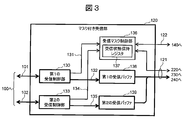
- FIG. 3 is a block diagram showing a detailed configuration of the masked receiving unit 120.
- the masked receiving unit 120 receives data (normal time data) from the first communication unit 101 according to a predetermined protocol, and receives data from the second communication unit 102 according to a predetermined protocol (when degenerate).
- Second reception control unit 133 for receiving data first reception buffer 138 for storing reception data (normal time data) obtained from first reception data interface 132, and second reception data interface 135
- a second reception buffer 139 for storing reception data (degenerated data) is provided.
- the masked reception unit 120 also includes a reception mask control unit 136.
- the first reception control unit 130 informs the first reception state notification interface 131 of the reception state (reception process completion and reception process in progress). Error detection of) is output.
- means defined by a protocol to which the first communication means 101 conforms such as a check of a cyclic redundancy check (CRC) code added to transmission data.
- CRC cyclic redundancy check
- the second reception control unit 133 When the reception process defined by the protocol conforming to the second communication unit 102 is completed, the second reception control unit 133 notifies the second reception state notification interface 134 of the reception state (reception process completion and reception process in progress). Error detection of) is output.
- Mean defined by a protocol to which the second communication means 102 conforms such as checking a cyclic redundancy check (CRC) code added to transmission data, is used.
- CRC cyclic redundancy check
- the reception mask control unit 136 receives the reception status of the first reception control unit 130 acquired via the first reception status notification interface 131 and the second reception status acquired via the second reception status notification interface 134. In addition to the reception state of the control unit 133, reception mask setting information designating the validity of the reception mask operation by itself is held in the reception state holding register 137.
- the reception mask control unit 136 further outputs a reception state notification generated by a procedure described later from the reception state control interface 122 to the operation mode control unit 140 based on the data held in the reception state holding register 137. Further, when the reception mask control unit 136 receives the update request for the reception state holding register 137 from the reception state control interface 122, the reception mask control unit 136 performs the requested update process.
- the reception interface 121 as an interface with the second control application 220, the first degenerate mode system software 230, and the second degenerate mode system software 240 includes a first receive buffer 138 and a second receive buffer 138.
- an interface that enables acquisition of a part or all of the held data in the reception state holding register 137 may be included.
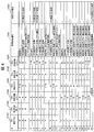
- FIG. 4 is a table showing the relationship between the information held in the reception state holding register 137 and the operation (reception state notification, reception mask update) of the reception mask control unit 136 based on the information.
- the reception state holding register 137 is configured to be able to hold the following setting information or data indicating the state information as an example.
- TP1 reception mask setting (C101) for setting whether to mask the completion notification to the operation mode control unit 140 when reception is completed
- TP1 reception state (completion) indicating whether the first reception control unit 130 has completed the reception process
- C102 TP1 reception state
- error indicating whether or not an error is detected during the reception processing of the first reception control unit 130
- TP2 reception mask setting (C201) that sets whether or not to mask the completion notification to the operation mode control unit 140 when reception is completed
- TP2 reception state (completion) indicating whether or not the second reception control unit 133 has completed the reception process
- C203 TP2 reception state (error) indicating whether or not an error is detected during the reception process of the second reception control unit 133
- the reception state holding register 137 independently sets information on the reception mask setting (C101, C201) in response to an update request from the reception interface 121 or the reception state control interface 122 (Y: mask is valid, The reception completion notification is invalidated) or cleared (N: the mask is invalidated, and the reception completion notification is validated).
- reception state holding register 137 sets (Y: reception completed) or clears (N: reception incomplete) information about the reception state (completed) (C102, C202) according to an instruction from the reception mask control unit 136. Can be configured. In addition, the reception state holding register 137 can only clear the information regarding the reception state (complete) (C102, C202) (N: reception incomplete) in response to a request from the reception interface 121 or the reception state control interface 122. Can also be configured.
- the reception status holding register 137 can set the information regarding the reception completion (error) (C103, C203) to be valid only when the reception status (completion) is Y (reception completion). Further, the reception state holding register 137 can be set (Y: there is an error) or clear (N: there is no error) for the information about the reception completion (error) (C103, C203) according to the instruction of the reception mask control unit 136. is there. Alternatively, it may be configured such that only clearing (N: no error) is possible in response to a request from the receiving interface 121 or the receiving state control interface 122.
- a setting independent of the reception mask setting (C101, C201) (hereinafter referred to as "extended reception mask setting”) It may be added as data to be held in the reception state holding register 137.
- any one of the following operations (1) to (3) can be set independently for each communication unit.
- the reception mask control unit 136 regarding the communication means of the first communication means 101 and the second communication means 102, for which the reception processing is completed first and the reception mask is set to be invalid. Outputs a reception status notification (C301) relating to the communication means from the reception status control interface 122. If the extended reception mask setting is added, the setting is also reflected.
- the reception mask is updated (C302) so as to suppress the notification of the reception status regarding the communication means for which the reception process is not completed.
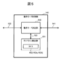
- FIG. 5 is a block diagram showing a detailed configuration of the operation mode control unit 140.
- the operation mode control unit 140 includes an operation mode determination unit 150 and a deadline detection unit 151 including one or more timers 152 (152a and 152b) capable of counting down.
- the operation mode determination unit 150 and the deadline detection unit 151 are interconnected by the deadline notification interface 153 for transmitting the data indicating that the count value of each of the timers 152 is less than or equal to zero (underflow).
- the operation mode control unit 140 determines the data reception status for each control cycle Tc and switches the operation mode.
- the deadline detection unit 151 has a function of detecting whether or not data is normally received within a predetermined time within a predetermined control cycle.
- the operation mode determination unit 150 of the second microcomputer 20 is based on the reception status notification acquired from the reception status control interface 122 and the deadline detection information acquired from the deadline detection unit 151 via the deadline notification interface 153.
- the operation mode is determined, and the result of the determination is output to the operation mode control interface 141 to notify the scheduling control unit 160.
- the operation mode control unit 140 is also configured to be able to receive a control cycle start trigger that specifies the start timing of the control cycle. Upon receiving the control cycle start trigger, the operation mode control unit 140 sets the count values of the one or more timers 152 to respective predetermined initial count values, and then starts the countdown operation of the timer 152. At the same time, the operation mode control unit 140 requests the reception mask control unit 136 in the masked reception unit 120 via the reception state control interface 122 to initialize the data held in the reception state holding register 137. Specifically, the held data C101, C102, C103, C201, C202, C203 are cleared. However, the contents of the extended reception mask setting are retained.
- the deadline time Tr2 can be set to a time longer than the above-mentioned TP1 reception window Tr1.
- the operation mode determination unit 150 determines the operation mode of the second microcomputer 20 by the following process flow based on the deadline information from the deadline notification interface 153 and the reception status notification (C301) from the reception status control interface 122. Then, the decision information is output to the operation mode control interface 141 and transferred to the scheduling control unit 160.
- step S101 first, by underflow of the timer 152a, it is confirmed whether or not the deadline time Tr2 has elapsed (deadline detection) from the start of the control cycle (step S101).
- step S101: Yes it is determined that a failure has occurred in both the first communication means 101 and the second communication means 102, and the operation mode control interface 141 determines that a failure has occurred.
- a transition to the degenerate mode 2 is requested (step S107).
- the scheduling control unit 160 triggers (instructs) the execution of the second reduced mode system software 240 by the execution control interface 163 to the second reduced mode system software.
- step S101 If the deadline detection is not recognized (step S101: No), then it is confirmed whether the reception status notification (C301) is "waiting for reception” (step S102), and if it is "waiting for reception” (step S102). (S102: Yes), the process returns to step S101, and the above loop is repeated until deadline detection or a reception status notification indicating completion of reception of either the first communication means 101 or the second communication means 102 is obtained. Be done.
- reception status notification is not "waiting for reception” (step S102: No)
- reception status notification C301 is "TP1 reception completion (normal)”
- step S103 If it is “TP1 reception completed (normal)” (step S103: Yes), it is determined that the normal time data can be normally received from the first communication unit 101, and the operation mode control interface 141 shifts to the normal mode. Required (step S105). Upon receiving this request, the scheduling control unit 160 triggers the execution of the second control application 220 by the execution control interface 161 to the second control application.
- step S103 No
- the reception status notification (C301) is “TP2 reception completion (normal)”.
- step S104 If “TP2 reception complete (normal)” (step S104: Yes), it is determined that the first communication unit 101 has a failure, but it is determined that the degenerate data can be normally received from TP2, and the operation mode control is performed.
- the interface 141 requests the transition to the first degenerate mode (step S106).
- the scheduling control unit 160 Upon receiving this request, the scheduling control unit 160 triggers the execution of the first degraded mode system software 230 by the execution control interface 162 to the first degraded mode system software.
- step S104 when the reception status notification is not “TP2 reception completed (normal)” (step S104: No), it is determined that a failure has occurred in both the first communication unit 101 and the second communication unit 102. Then, the operation mode control interface 141 requests the transition to the second degenerate mode (step S107). The scheduling control unit 160 that has received this request triggers the execution of the second degraded mode system software 240 by the execution control interface 163 to the second degraded mode system software.
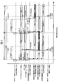
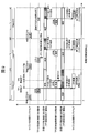
- FIG. 7 and 8 are timing charts showing in detail the operation mode determination mechanism of the operation mode control unit 140 based on the presence or absence of underflow in the timers 152b and 152a for measuring the TP1 reception window Tr1 and the deadline time Tr2, respectively.
- Cases 1-1 to 1-3 are shown. 7 and 8 respectively show timing charts in the case of Case 1-1 on the left side thereof, and Cases 1-2, 1-3 on the right side thereof. Cases 1-1 to 1-3 show actions that can occur due to changes in various situations, and are independent of each other.
- ⁇ Case1-1> As shown in FIGS. 7 and 8, in Case 1-1, the first communication unit 101 precedes the second communication unit 102 and normally completes the reception of the normal time data in the TP1 reception window Tr1.
- the control cycle shows the case where the second control application 220, which is the process for the normal mode, is executed.
- the operation mode determination unit 150 in the operation mode control unit 140 receives the control cycle start trigger (T) from the scheduling control unit 160 via the operation mode control interface 141.
- the operation mode determination unit 150 that has received the trigger (T) instructs the reloading (L) of the initial count value to the timers 152a and 152b by the deadline notification interface 153, and at the same time, the reception state control interface 122 receives the reception state.
- An initialization (reset) request (R) of the holding register 137 is output.
- the deadline detection unit 151 that has received the reload (L) instruction causes the timers 152a and 152b to perform predetermined counts for measuring the progress of the deadline time Tr2 and the TP1 reception window Tr1, respectively, based on the beginning of the control cycle. Set the value and instruct to start the decrement operation. Further, the reception mask control unit 136 that has received the initialization request (R) clears all the held data other than the extended reception mask setting in the reception state holding register 137, so that the first communication unit 101 and the second It is set so that the reception completion notification in the communication means 102 is valid.
- the reception mask control unit 136 updates the contents of the reception state holding register 137 to reflect the information (corresponding to #5 in FIG. 4), and at the same time notifies the reception state control interface 122 of the reception state notification “TP1 reception completed. (Normal)" is output.
- the TP2 reception mask (C201) transition to #7 in FIG. 4 for the second communication unit 102 that has not completed reception, the reception state within the control cycle is determined (FIG. 7). reference).
- the operation mode determination unit 150 which was monitoring the reception state notification of the reception state control interface 122, determines the transition to the normal mode based on the operation mode determination flow of FIG. 6, and the scheduling control unit via the operation mode control interface 141. Instruct (C) the transition to 160. At the same time, the operation mode determination unit 150 instructs the deadline notification interface 153 to stop the decrement operation of the timers 152a and 152b in order to suppress the occurrence of a false underflow event (see FIG. 7).
- the scheduling control unit 160 that has received the transition instruction (C) instructs the execution of the second control application 220 by the execution control interface 161 to the second control application.
- the first communication means 101 cannot normally complete the reception of the normal data within the TP1 reception window Tr1 (reception is not completed, or reception is completed but during reception). Any of the error detection), the second communication unit 102 normally completes the reception of the degeneration data by the deadline time Tr2. Therefore, the control cycle is the first degeneration mode process, that is, the first degeneration mode. The case where the degenerate mode system software 230 is executed is shown.
- the operation mode determination unit 150 receives the control cycle start trigger (T) from the scheduling control unit 160 via the operation mode control interface 141.
- the operation mode determination unit 150 that has received the trigger (T) instructs the reloading (L) of the initial count value to the timers 152a and 152b by the deadline notification interface 153, and at the same time, the reception state control interface 122 receives the reception state.
- the initialization request (R) of the holding register 137 is output.
- the deadline detection unit 151 instructs the timers 152a and 152b to measure the progress of the deadline time Tr2 and the TP1 reception window Tr1 with reference to the beginning of the control cycle. Set the count value of and instruct to start the decrement operation. Further, the reception mask control unit 136 that has received the initialization request (R) clears all the held data other than the extended reception mask setting in the reception state holding register 137. As a result, the reception completion notifications of the first communication unit 101 and the second communication unit 102 become valid.
- the operation mode determination unit 150 instructs the deadline notification interface 153 to stop the decrement operation of the timer 152b and outputs a TP1 reception mask setting request (M) to the reception state control interface 122.
- the reception mask control unit 136 sets the contents of the TP1 reception mask (C101) in the reception state holding register 137 (corresponding to #13 in FIG. 4) to receive the TP1 reception. After the elapse of the window time, the setting is updated so that only the reception completion notification in the second communication unit 102 becomes valid.
- the second reception control unit 133 completes the normal reception of the degenerate data by the deadline time Tr2
- the information is transmitted to the reception mask control unit 136 by the second reception state notification interface 134.
- the reception mask control unit 136 updates the contents of the reception state holding register 137 to reflect the information (corresponding to #15 in FIG. 4). Specifically, the TP reception state (completion) is switched from N to Y. At the same time, the reception mask control unit 136 outputs the reception state notification “TP2 reception completion (normal)” to the reception state control interface 122. Since the TP1 reception mask has already been set, the reception state within the control cycle is fixed.
- the operation mode determination unit 150 which was monitoring the reception state notification of the reception state control interface 122, determines the transition to the first degenerate mode based on the operation mode determination flow of FIG. 6, and via the operation mode control interface 141.
- the scheduling control unit 160 is instructed (C) about the transition.
- the operation mode determination unit 150 instructs the deadline notification interface 153 to stop the decrement operation of the timer 152a in order to suppress the occurrence of a false underflow event.
- the scheduling control unit 160 Upon receiving the transition instruction (C), the scheduling control unit 160 instructs the execution control interface 162 to the first degenerate mode system software to execute the first degenerate mode system software 230.
- ⁇ Case 1-3> As shown on the right side of FIG. 8, in Case 1-3, the first communication unit 101 cannot normally complete the reception of the normal data within the TP1 reception window Tr1 (reception is not completed, or reception is completed but during reception). Either the error is detected), and the second communication unit 102 cannot normally complete the reception of the degenerate data by the deadline time Tr2 (either the reception is not completed, or the reception is completed but the error is detected during the reception). Therefore, the control cycle shows a case where the second degenerate mode system software 240, which is the process for the second degenerate mode, is executed.
- the deadline detection unit 151 that has received the reload (L) instruction causes the timers 152a and 152b to perform predetermined counts for measuring the progress of the deadline time Tr2 and the TP1 reception window Tr1, respectively, based on the beginning of the control cycle. Set the value and instruct to start the decrement operation. Further, the reception mask control unit 136 that has received the initialization request (R) clears all the contents other than the extended reception mask setting in the reception state holding register 137, so that the first communication unit 101 and the second communication unit. It is set so that the reception completion notification in the means 102 becomes valid.
- the operation mode determination unit 150 instructs the deadline notification interface 153 to stop the decrement operation of the timer 152b and outputs a TP1 reception mask setting request (M) to the reception state control interface 122.
- the reception mask control unit 136 sets the contents of the TP1 reception mask (C101) in the reception state holding register 137 (corresponding to #13 in FIG. 4) to receive the TP1 reception. After the passage of the window Tr1, the setting is updated so that only the reception completion notification in the second communication unit 102 becomes valid.
- a TP2 reception mask setting request may be output to the reception state control interface 122 as an additional process not shown.
- the reception mask control unit 136 sets the content of the TP2 reception mask (C201) in the reception state holding register 137 (corresponding to #19 in FIG. 4). After the deadline time Tr2 has passed, the setting may be updated so that any reception completion notification of the first communication unit 101/second communication unit 102 becomes invalid.
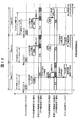
- Case 2-1 shown on the left side of FIGS. 9 and 10 indicates a case where the first communication unit 101 completes the normal reception of the normal data in the TP1 reception window Tr1 prior to the second communication unit 102. There is. In this case, the second microcomputer 20 in the control cycle executes the normal-time data reception process as a part of the process of the second control application 220.
- Case 2-2 shown in the center of FIG. 9 shows a case where the first communication means 101 has completed the reception within the TP1 reception window but has detected an error during the reception. In this case, the reception completion notification of the first communication unit 101 is masked based on the extended reception mask setting.
- the second communication unit 102 when the second communication unit 102 normally completes the reception of the degenerate data by the deadline time Tr2, the reception completion notification of the second communication unit 102 is not masked, and the operation mode is set by the reception state control interface 122. It is output to the control unit 140. Therefore, the second microcomputer 20 in the control cycle executes the degeneration data receiving process as a part of the process of the first degeneration mode system software 230.
- the TP1 reception mask is set when the normal reception of the second communication unit 102 is completed. Therefore, even if the reception of the normal time data is normally completed by the first communication unit 101 after that time point, the reception processing of the normal time data that is unnecessary for the execution of the first degenerate mode system software 230 is executed. It will not be done.
- Case 2-4 shown in the center of FIG. 10 is the first communication means 101, which normally completes the reception of the normal data in the TP1 reception window Tr1 prior to the second communication means 102, while The communication means 102 also shows the case where the reception is completed by the deadline time Tr2 but an error is detected during the reception.
- the second microcomputer 20 in the control cycle executes the normal-time data reception process as a part of the process of the second control application 220.
- the second communication unit 102 also completes the reception by the deadline time Tr2 but detects an error during the reception, and therefore the reception completion notification is masked by the mask setting in the reception mask control unit 136 based on the extended reception mask setting.
- the second control application Since the TP2 reception mask is set at the time point when the first communication means 101 completes the normal reception, even if the second communication means 102 side normally completes the reception by the retransmission processing after that time point, the second control application The process of receiving degenerate data, which is unnecessary for executing 220, is not executed. As a result, the load factor of the second microcomputer 20 is reduced.
- the second communication means 102 does not complete the reception by the deadline time Tr2 due to the failure of the transmission path.
- the reception mask control unit 136 sets the TP2 reception mask. Even if the second communication unit 102 normally completes the reception after that time point, the reception processing of the degenerate data, which is unnecessary for the execution of the second control application 220, is not executed. As a result, the load factor of the second microcomputer 20 is reduced.
- ⁇ Case3-1> In Case 3-1 shown on the left side of FIG. 11, the first communication unit 101 has completed reception of normal data in the TP1 reception window Tr1, but an error has been detected during reception, and the second communication unit 102 also has a deadline time. This shows a case where the degenerate data has been completely received by Tr2 but an error has been detected during the reception. In this case, the reception completion notification of the first communication unit 101 is masked based on the extended reception mask setting.
- the second communication means 102 also completes the reception by the deadline time Tr2, but since an error was detected during the reception, the reception completion notification of the second communication means 102 is masked based on the extended reception mask setting.
- the deadline time Tr2 elapses without the reception completion notification of either the first communication unit 101 or the second communication unit 102
- the second microcomputer 20 in the control cycle detects the deadline to perform the second degeneration.
- the mode system software 240 is executed.
- ⁇ Case 3-2> In Case 3-2 shown on the right side of FIG. 11, the first communication means 101 side does not complete the reception within the TP1 reception window Tr1 due to the failure of the transmission path, and the second communication means 102 also has the deadline time due to the failure of the transmission path. The case where reception is not completed by Tr2 is shown. In this case, the deadline time Tr2 elapses without any reception completion notification from the first communication unit 101/second communication unit 102.
- the second microcomputer 20 in the control cycle executes the second degenerate mode system software 240 by detecting the deadline.
- ⁇ Case4-2> In Case 4-2 shown in the center of FIG. 12, since the reception completion timing is delayed due to the retransmission due to the failure of the transmission path, the first communication unit 101 normalizes the normal data after the passage of the TP1 reception window Tr1. The case where reception is completed is shown. In this case, since the TP1 reception mask is set at the time when the TP1 reception window Tr1 has passed, the normal-time data reception process is not executed. On the other hand, regarding the second communication means 102, it is assumed that the degenerate data is normally received by the deadline time Tr2. In this case, the second microcomputer 20 in the control cycle executes the degenerate data receiving process as a part of the process of the first degenerate mode system software 230.
- ⁇ Case4-3> In Case 4-3 shown on the right side of FIG. 12, the first communication unit 101 normalizes the normal data after the passage of the TP1 reception window Tr1 because the retransmission has occurred due to the failure of the transmission path and the reception completion timing has been delayed. The case where reception is completed is shown. On the other hand, regarding the second communication means 102, it is assumed that the reception is completed by the deadline time Tr2, but an error is detected during the reception.
- the second communication means 102 Since the TP1 reception mask is set when the TP1 reception window Tr1 has passed, the normal-time data reception process is not executed. Also, the second communication means 102 has completed the reception by the deadline time Tr2, but since an error was detected during reception, the reception completion notification of the second communication means 102 is masked based on the extended reception mask setting. It For this reason, the deadline time Tr2 elapses without receiving the reception completion notification of either the first communication unit 101 or the second communication unit 102. Therefore, the second microcomputer 20 in the control cycle executes the second degenerate mode system software 240 by detecting the deadline.
- the masked reception unit 120 masks the reception of unnecessary data. It is cut off by the action. As a result, it is possible to provide a vehicle control device that can ensure real-time communication and reduce the load factor of the arithmetic and control unit.
- a vehicle control device 1 according to a second embodiment of the present invention will be described with reference to FIGS. 13 to 16. Since the configuration of the device of the second embodiment is substantially the same as that of the first embodiment, duplicated description will be omitted. However, as will be described later, since the timing control by the transmission unit with delay 100 is unnecessary, the delay control of the transmission unit with delay 100 is invalidated, or the transmission unit with delay 100 is replaced with a normal transmission unit. obtain.
- an operation mode control method that spans multiple control cycles is adopted.
- 13 to 16 show the operation of the second microcomputer 20 when the method is adopted. Unlike the control method described in the first embodiment, FIGS. 13 to 16 show that only one of the first communication means 101 and the second communication means 102 receives in one control cycle. Completion notification is set to valid (reception mask invalid).
- the operation mode determination unit 150 determines the state of reception by the first communication unit 101 or the second communication unit 102 in one control cycle, and determines the operation mode according to the result of the determination. The operation mode determined by the operation mode determination unit 150 is executed not in the control cycle (first control cycle) but in the control cycle next to the control cycle (second control cycle).
- the reception of the normal time data and the degeneration data may be completed within one control cycle, and the operation mode determined thereafter need not be completed within the cycle. It is executed in the next control cycle. Further, the order relation of the reception completion timing between the first communication means 101 and the second communication means 102 is not questioned. Therefore, the transmission timing control of the normal time data and the degenerate data in the delayed transmission unit 100 is unnecessary.
- This method has an advantage that the difficulty of timing design in which the processing time is allocated in time series to each processing within the control cycle is reduced.
- reception completion notification mask for normal mode that allows reception completion notification of only normal data is set.
- the reception completion notification on the side of the first communication unit 101 that transfers normal data is valid (mask invalid)
- the reception completion notification on the side of the second communication unit 102 that transfers degenerate data is invalid (masked).
- the extended reception mask setting is always invalid (the completion notification is valid even when an error is detected).
- the number of timers 152 in the second embodiment may be one (only 152a).
- the deadline time Tr2 is defined as the time during which the reception processing of the first communication unit 101 or the second communication unit 102, which is obtained by subtracting the time required for switching the TP1/TP2 reception mask described below from the control cycle, is set as the deadline time Tr2.
- the count value to be measured can be set in the timer 152a.
- Case 5-2 shown in the center of FIG. 13, in the state where the reception completion notification mask for the normal mode is set, the first communication means 101 side has completed the reception by the deadline time Tr2, but detected an error during reception.
- the second microcomputer 20 in the control cycle sets the reception mask setting pattern of the next control cycle to the first degeneration mode reception completion notification as the first error processing which is a part of the second control application 220. Set in the mask.
- the second communication unit 102 normally completes the reception of the degenerate data by the deadline time Tr2 of the control cycle, but since the TP2 reception mask is set, the degenerate data reception process is not executed. Absent.
- Case 5-3 illustrated on the right side of FIG. 13, Case 5-2 occurs and the first degeneration mode reception completion notification mask is set, and the second communication unit 102 is set to deadline time Tr2 in the next control cycle.
- the processing when the data at the time of degeneration is normally received is shown.
- the second microcomputer 20 in the next control cycle executes the degenerate data receiving process as a part of the process of the first degenerate mode system software 230. Further, the reception mask setting pattern of the next control cycle is not changed, and the first degeneration mode reception completion notification mask setting is maintained.
- Case 5-4 occurs, the first degeneration mode reception completion notification mask is set, and the second communication unit 102 side receives by the deadline time Tr2 in the control cycle. Although it is completed, it shows the case where an error is detected during reception in the next control cycle.
- the second microcomputer 20 in the control cycle sets the reception mask setting pattern of the next control cycle for the second degeneration mode as the second error processing which is a part of the first degeneration mode system software 230. Set in the reception completion notification mask.
- the degeneration level is changed according to the severity of the failure.
- Case 5-5 illustrated in FIG. 14 illustrates processing in the next control cycle when the second degeneration mode reception completion notification mask is set by Case 5-4.
- the second degenerate mode system software 240 is executed without waiting for the completion of reception of the normal data or the degenerate data.
- the blockage of the first communication unit 101/the second communication unit 102 as a part of a predetermined initialization process for the entire vehicle control device 1 or the second microcomputer 20. It may be possible to return to the setting state of the reception completion notification mask for normal mode.
- the reception completion notification mask for the normal mode is set after Case 5-1 occurs, but the reception completion notification of the first communication unit 101 is not performed in the next control cycle.
- the figure shows the case where the deadline time Tr2 has elapsed.
- the second microcomputer 20 in the control cycle uses the deadline notification by the deadline notification interface 153 as a trigger, and performs the first communication process as the first error processing that is a part of the second control application 220.
- the reception mask setting pattern of the next control cycle is changed to the reception completion notification mask for the first degenerate mode.
- the second communication unit 102 has normally received the degenerate data by the deadline time Tr2, but the TP2 reception mask is set, so that the degenerate data receiving process is not executed.
- Case 5-7 illustrated in FIG. 15, after the occurrence of Case 5-1 and Case 5-6, the second communication unit 102 side waits until the deadline time Tr2 with the reception completion notification mask for the first degenerate mode set. Shows the case where the degenerate data has been normally received.
- the second microcomputer 20 in the control cycle executes the degeneration data receiving process as a part of the process of the first degeneration mode system software 230. Further, the reception mask setting pattern of the next control cycle is not changed, and the first degeneration mode reception completion notification mask setting is maintained.
- Case 5-8 shows the case where the deadline time Tr2 has elapsed without the reception completion notification of (2) being issued.
- the second microcomputer 20 in the control cycle triggered by the deadline notification by the deadline notification interface 153, performs the second error processing, which is a part of the first degraded mode system software 230, as the second error processing. It is confirmed that the reception on the side of the communication means 102 is incomplete, and the reception mask setting pattern of the next control cycle is changed to the second degeneration mode reception completion notification mask.
- the degeneration level can be appropriately changed according to the severity of the failure.
- Case 5-9 shown on the right side of FIG. 16 is executed.
- the second degeneration mode system software 240 is executed without waiting for the reception completion of the normal data or the degeneration data. ..
- the second degeneration mode system software 240 is executed without waiting for the reception completion of the normal data or the degeneration data. ..
- the blockage of the first communication unit 101/the second communication unit 102 as a part of a predetermined initialization process for the entire vehicle control device 1 or the second microcomputer 20. It may be possible to return to the setting state of the reception completion notification mask for normal mode.
- Second reception status notification interface 135... Second reception data interface, 136... Reception mask control 137... Reception state holding register, 138... First reception buffer, 139... Second reception buffer, 140... Operation mode control section, 141... Operation mode control interface, 150... Operation mode determination section, 151... Deadline Detection unit, 152, 152a, 152b... Timer, 153... Deadline notification interface, 160... Scheduling control unit, 161-163... Execution control interface, 210... First control application, 211... Transmission interface, 220... Second Control application, 230... First degenerate mode system software, 240... Second degenerate mode system software, 900... Microcomputer, 901... Ethernet adapter, 902... Connection port, 903...
- Ethernet cable 910... Ethernet switch, 911 ... control table, 912... switch matrix control interface, 913... switch matrix, 914, 914a, 914b, 914c, 914d, 914e, 914f, 914g, 914h... switch connection port, 915-1, 915-2... Ethernet cable
Landscapes
- Engineering & Computer Science (AREA)
- Computer Networks & Wireless Communication (AREA)
- Signal Processing (AREA)
- Computer Security & Cryptography (AREA)
- Communication Control (AREA)
Abstract
通信のリアルタイム性を保証すると共に、演算制御装置の負荷率を軽減することを可能にした通信制御装置を提供する。第1の演算制御装置及び第2の演算制御装置の間を第1及び第2の通信手段で冗長接続し、それぞれ第1及び第2のデータを送受信する。マスク付き受信部は、前記第1のデータ又は前記第2のデータのいずれか一方を正常に受信完了した際には他方受信動作をマスクし、一方についてのみ受信処理を行う。
Description
本発明は、通信制御装置に関し、特に、複数のマイコンを組み合わせて所定の制御処理を実行するとともに、マイコン(演算制御装置)間を相互に冗長接続する通信方式を備えた通信制御装置に関する。
自動車に関連する様々な社会的課題を解決する手段として、自動運転に対するニーズが増大している。運転の自動化レベルを示す指標としてはSociety of Automotive Engineers(SAE)によるJ3016がよく知られている。レベル1に相当するアダプティブクルーズコントロールやレーンキーピングアシストシステムといった、運転者の操作を部分的に支援する機能はすでに実用化されている。一方で、運転者が運転に介入することを不要にしたレベル4やレベル5対応の自動運転車は、それぞれ2025年及び2030年を目途に市場投入されると期待されている。それらの実現に向け、従来の完成車メーカやサプライヤ各社に加え、例えば画像認識や機械学習に強みをもつ異業種からの参入プレーヤやベンチャ企業が開発に鎬を削っているのが現状である。
車両の縦方向(加減速)と横方向(ステアリング)の運動を同時に制御するレベル2以上の自動運転車では、自動運転ECUと呼ばれる車両制御装置が車両制御の中心的役割を担うことになる。自動運転ECUには、(1)自車及び周囲の環境に関するデータを取得するセンシング、(2)取得したセンサデータや地図情報を統合し分析する状況認識、(3)認識結果に基づき安全な走行軌道を生成する行動計画、(4)行動計画を自車の運動に反映させるためのアクチュエータ制御、等を含む複雑な各種情報処理を、大規模なデータに対しリアルタイムに実行することが求められる。
自動運転ECUのアーキテクチャや実装方式に関し共通プラットフォームと呼べるものは現在のところ存在しない。上記情報処理のステージごとに独立したマイコン上で動作する複数の機能モジュールを実装し、それら複数の機能モジュール間を通信手段により相互接続することで各処理を連携させる分散システムは、技術的なメリットが多いと考えられている。
一方で、上記のモジュラ設計を導入することにより、複数の機能モジュール間の接続が新たなボトルネックを発生させる可能性がある。すなわち、制御処理全体を複数のマイコンによりソフトウェアパイプラインとして実行するため、処理の中間データをモジュールの主要構成デバイスであるマイコン間でリアルタイム(例えば10ミリ秒オーダ)に受け渡す必要が生じ、このような中間データのやり取りがボトルネックを発生させ得る。
加えて、自動車向け応用においては、システムを構成する装置の一部が故障した場合でも、システム全体として所定の制御性と安全状態を維持することが期待される。そのため、自動運転ECUのような特に重要度の高い装置においては、マイコン間通信手段を含むハードウェアの冗長構成を採用することが求められる。
自動車向け応用ほどのリアルタイム性が要求されない分野においては、非特許文献1に開示されているように、イーサネットスイッチ(「イーサネット」は登録商標)を介して通信経路を冗長化するとともに、所定のプロトコルにより切り替えを含む経路管理を行う実装が公知である。
図17は、従来方式により経路冗長化したマイコン間通信システムの一例を示す。マイコン900はイーサネットプロトコルを処理するイーサネットアダプタ901を内蔵し、マイコン外部への接続ポート902及びイーサネットケーブル903を介して、マイコン外部とのイーサネット通信を行う。マイコン900に接続ポート902が1つのみ実装されている場合には、マイコン900ごとに外部にイーサネットスイッチ910が追加され、イーサネットケーブル903がイーサネットスイッチ910に備えられた複数のスイッチ接続ポート914(914a~914h)のいずれかに接続される。
更に、複数のスイッチ接続ポート914を利用して複数のイーサネットスイッチ910間をイーサネットケーブル915-1、915-2…により並列接続することで、マイコン間通信の経路冗長化を実現することができる。
イーサネットスイッチ910は、スイッチ接続ポート914間のフレーム転送ルールに関する制御情報を保持する制御テーブル911を有し、スイッチマトリクス制御インタフェース912を介してスイッチマトリクス913の動作を制御する。これにより、指定されたスイッチ接続ポート914間でフレーム転送が実行される。
更に、イーサネットスイッチ910はスパニングツリープロトコル(STP:Spanning Tree Protocol)をサポートすることで、STPの定める手順に従い、ループ状の通信経路に起因するブロードキャストストームを抑止する目的で冗長化された2つの通信経路のうち一方のみのフレーム転送を有効とする。また、イーサネットスイッチ910は、STPの定める手順に従い、ネットワーク管理用フレームの不達により通信経路の障害を検出した場合には、障害を含まない側の通信経路を有効とするよう、制御テーブル911の内容を適切に更新する。これにより、通信経路の冗長化及び障害時の経路切り替え制御が実現される。
ただし、STPの仕様により障害発生から経路切り替え完了までの数10秒間は通信不可となるため、リアルタイム性の要件を満たすことはできない。通信経路の冗長化によりマイコン間通信の耐障害性向上を図る場合、従来方式ではプロトコルに依存する切り替え時間に加え、通信エラー検出を起点とするリカバリ処理に伴うオーバヘッドが制御周期とは非同期に発生することで、通信のリアルタイム性を保証できなくなる虞がある。また冗長化された複数データの受信処理により演算制御装置(CPU)の負荷率が上昇する虞がある。
宇野俊夫(2011)『独習TCP/IP IPネットワーキング編』翔泳社
本発明は、通信のリアルタイム性を保証すると共に、演算制御装置の負荷率を軽減することを可能にした通信制御装置を提供することを目的とする。
本発明に係る通信制御装置は、第1の演算制御装置と第2の演算制御装置とを接続し、第1のデータを送受信する第1の通信手段と、前記第1の演算制御装置と前記第2の演算制御装置とを接続し、前記第1のデータとは異なる第2のデータを送受信する第2の通信手段と、前記第1の通信手段及び第2の通信手段に接続され、前記第1のデータ又は前記第2のデータのいずれか一方を正常に受信した際には、他方の受信動作をマスクするマスク付き受信部とを備えたことを特徴とする。
本発明に係る通信制御装置では、第1及び第2の演算制御装置の間を第1及び第2の通信手段で冗長接続し、それぞれ第1及び第2のデータを転送する。受信側では、第1のデータ又は第2のデータのいずれか一方を正常に受信完了した際には他方の受信動作をマスク付き受信部によりマスクし、一方についてのみ受信処理を行うことで、CPU負荷率の上昇を抑止することができる。従って、本発明によれば、通信のリアルタイム性を保証すると共に、演算制御装置の負荷率を軽減することを可能にした通信制御装置を提供することができる。
以下、添付図面を参照して本実施形態について説明する。添付図面では、機能的に同じ要素は同じ番号又は対応する番号で表示される場合もある。なお、添付図面は本開示の原理に則った実施形態と実装例を示しているが、これらは本開示の理解のためのものであり、決して本開示を限定的に解釈するために用いられるものではない。本明細書の記述は典型的な例示に過ぎず、本開示の特許請求の範囲又は適用例を如何なる意味においても限定するものではない。
本実施形態では、当業者が本開示を実施するのに十分詳細にその説明がなされているが、他の実装・形態も可能で、本開示の技術的思想の範囲と精神を逸脱することなく構成・構造の変更や多様な要素の置き換えが可能であることを理解する必要がある。従って、以降の記述をこれに限定して解釈してはならない。
[第1の実施の形態]
図1は、本発明の第1の実施の形態に係る車両制御装置1(通信制御装置)の構成を示す。車両制御装置1(ECU)は、当該装置に課せられた所定の制御処理のうち、それぞれ一部を実行する第1のマイコン10(第1の演算制御装置)及び第2のマイコン20(第2の演算制御装置)を備える。説明の簡単のため、図1では車両制御装置1が2個のマイコン10、20を有しているものとして説明をするが、車両制御装置1が2より大きい数のマイコンを有していてもよいことは言うまでもない。2より大きい数のマイコンが1つの車両制御装置に含まれている場合でも、その中の2つのマイコンの構成を、以下の説明に従って構成することが可能である。
図1は、本発明の第1の実施の形態に係る車両制御装置1(通信制御装置)の構成を示す。車両制御装置1(ECU)は、当該装置に課せられた所定の制御処理のうち、それぞれ一部を実行する第1のマイコン10(第1の演算制御装置)及び第2のマイコン20(第2の演算制御装置)を備える。説明の簡単のため、図1では車両制御装置1が2個のマイコン10、20を有しているものとして説明をするが、車両制御装置1が2より大きい数のマイコンを有していてもよいことは言うまでもない。2より大きい数のマイコンが1つの車両制御装置に含まれている場合でも、その中の2つのマイコンの構成を、以下の説明に従って構成することが可能である。
第1のマイコン10及び第2のマイコン20の間の接続は、第1の通信手段101(以下TP1とも記す)と第2の通信手段102(以下TP2とも記す)による冗長接続の態様で構成される。特に制限されないが、説明を簡潔にするため、マイコン間のデータ通信方向は第1のマイコン10(送信側)から第2のマイコン20(受信側)に限定して説明を行う。第1の通信手段101と第2の通信手段102は、準拠する規格/仕様は共通であってもよいし、その一部又は全部が異なるものであってもよい。一例としては、第1の通信手段101はPCIeなどの高速インタフェースであり、第2の通信手段102はCANやSPI等の低速インタフェースであるが、これに限られるものではない。
第1の通信手段101は、所定の制御処理の実行に必要な全制御データ(以下「通常時データ」又は「第1のデータ」とも記す)の転送に利用するインタフェースである。また、第2の通信手段102は、冗長接続を構成する第1の通信手段101と第2の通信手段102の一方に通信障害が生じた場合に実行する縮退処理に必要な制御データ(以下「縮退時データ」又は「第2のデータ」とも記す)の転送に利用するインタフェースである。
どのデータを縮退時データとするかは、装置構成、ネットワーク構成、通信路の状況等に応じて適宜決定することができる。縮退時データは、通常時データのうちの一部のデータとしてもよい。一例としては、自動運転に必要な全てのデータのうち、緊急停止に必要なデータのみを縮退時データとして抽出することができる。又は、縮退時データは、通常時データの一部又は全部から所定のアルゴリズムに基づき生成したダイジェストデータであってもよい。あるいは、縮退時データは、それらの任意の組み合わせであってもよい。
なお、2つのマイコン10、20の間のインタフェースの数は、2に限定されるものではなく、3以上であってもよい。3以上のインタフェースのうちの幾つかが通常時データの転送に利用され、それ以外のインタフェースが縮退時データの転送に利用可能とされていればよい。
なお、2つのマイコン10、20の間のインタフェースの数は、2に限定されるものではなく、3以上であってもよい。3以上のインタフェースのうちの幾つかが通常時データの転送に利用され、それ以外のインタフェースが縮退時データの転送に利用可能とされていればよい。
第1のマイコン10は、所定の制御処理の一部に相当する第1の制御アプリケーション210を実行可能に構成されている。第1のマイコン10は、遅延付き送信部100を備えている。第1の制御アプリケーション210は、実行の結果得られた通常時データ及び縮退時データを、遅延付き送信部100が提供する送信インタフェース211を利用し第2のマイコン20に送出する。遅延付き送信部100は、後述するように、通常時データの受信の完了を縮退時データの受信の完了に先行させるため、第1の通信手段101の転送処理よりも、第2の通信手段102の転送処理を遅延させる遅延処理を実行可能に構成されている。
第2のマイコン20は、第2の制御アプリケーション220、第1の縮退モード用システムソフトウェア230、及び第2の縮退モード用システムソフトウェア240を実行可能に構成されている。第2の制御アプリケーション220は、第1の制御アプリケーション210と同様に、所定の制御処理の一部に相当する処理を実行する。第1の縮退モード用システムソフトウェア230は、冗長接続に生じた通信障害が第1の段階である場合に選択・実行される。第2の縮退モード用システムソフトウェア240は、冗長接続に生じた通信障害が第2の段階である場合に選択・実行される。
また、第2のマイコン20は、マスク付き受信部120、動作モード制御部140、及びスケジューリング制御部160を備える。
マスク付き受信部120は、第1の通信手段101及び第2の通信手段102に接続され、各通信手段の受信状態や障害発生(受信未完了、又は受信処理中にエラー検出)の有無に基づき所定の手続きにより生成した受信状態通知を、受信状態制御インタフェース122から動作モード制御部140に対して出力する。
動作モード制御部140は、マスク付き受信部120の状態(マスク付き受信部120から受信した受信状態通知)及び/又は自身の内部状態に基づき、次に第2のマイコン20が遷移すべき状態(モード)を決定する。そして、動作モード制御部140は、動作モード制御インタフェース141経由でスケジューリング制御部160へ、第2のマイコン20が遷移すべき状態を指示する。
スケジューリング制御部160は、動作モード制御部140からの指示に従い、指示に従ったソフトウェアの実行を指示する。例えば、次に実行すべき(遷移すべき)ソフトウェアが第2の制御アプリケーション220の場合には、実行制御インタフェース161により、第2の制御アプリケーション220の実行が指示される。次に実行すべき(遷移すべき)ソフトウェアが第1の縮退モード用システムソフトウェアの場合には、実行制御インタフェース162により、第1の縮退モード用システムソフトウェアの実行が指示される。次に実行すべき(遷移すべき)ソフトウェアが第2の縮退モード用システムソフトウェアの場合には、実行制御インタフェース163により、第2の縮退モード用システムソフトウェアの実行が指示される。実行を指示されたソフトウェアは、マスク付き受信部120の提供する受信インタフェース121を利用してデータの受信を行う。実行を指示されたソフトウェアは、通常時データ及び/又は縮退時データの受信処理を行う。実行の指示に対象外とされたソフトウェアは、いずれのデータの受信処理も行わない。
図2は、遅延付き送信部100の詳細な構成の一例を示す。遅延付き送信部100は、一例として、送信トリガ制御部110、第1の送信バッファ114、第2の送信バッファ116、第1の送信制御部118、及び第2の送信制御部119を備える。
第1の送信バッファ114は、通常時データを第1の通信手段101を介して送信するために通常時データを一時格納するデータ記憶部である。第1の送信バッファ114に一時格納された通常時データは、第1の送信データインタフェース115を介し第1の送信制御部118に出力される。
また、第2の送信バッファ116は、縮退時データを第2の通信手段102を介して送信するために縮退時データを一時格納するデータ記憶部である。第2の送信バッファ116に一時格納された縮退時データは、第2の送信データインタフェース117を介し第2の送信制御部119に出力される。
第1の送信制御部118は、第1の送信データインタフェース115から取得した送信データ(通常時データの一部又は全部)を所定のプロトコルに従い第1の通信手段101に送出する。また、第2の送信制御部119は、第2の送信データインタフェース117から取得した送信データ(縮退時データの一部又は全部)を所定のプロトコルに従い第2の通信手段102に送出する。
送信トリガ制御部110は、第1の通信手段101及び第2の通信手段102への送信開始タイミング時間の差分を計測し、カウントダウン動作が可能なタイマ111を備える。送信トリガ制御部110は、送信トリガインタフェース112、113を介して、それぞれ第1の通信手段101へのデータの送信開始、及び第2の通信手段102へのデータの送信開始を指示するトリガを、第1の送信制御部118及び第2の送信制御部119に送信する。
なお、第1の制御アプリケーション210と遅延付き送信部100とのインタフェースとなる送信インタフェース211は、第1の送信バッファ114、第2の送信バッファ116への送信データ格納に加え、送信バッファの空き状態チェックや明示的な送信要求を可能とするインタフェースを含んでいてよい。
特に制限されないが、送信トリガ制御部110は、第1の制御アプリケーション210からの送信開始要求を受け、タイマ111のカウント値を所定の初期カウント値に設定する。その後、タイマ111にカウントダウン動作を開始させ、同時に送信トリガインタフェース112を介して、第1の通信手段101への通常時データの送信開始を指示する。
送信トリガ制御部110は更に、タイマ111のカウント値がゼロ以下(アンダフロー)となった時点でカウントダウン動作を停止させ、同時に第2の通信手段102への送信トリガインタフェース113を介して、第2の通信手段102への縮退時データの送信開始を指示する。なお、第1の通信手段101及び第2の通信手段102がいずれも一度の送受信動作で正常に通信が完了する(すなわち再送が発生しない)という条件下で、通常時データの受信完了時刻が縮退時データの受信完了時刻に対して先行するよう、タイマ111の初期カウント値を設定することができる。このように設定することで、通常時データの受信の完了を縮退時データの受信の完了に先行させることができ、データ送受信のオーバヘッドを低減することが可能になる。マスク付き受信部120は、受信の不要なデータをマスクすることにより演算制御装置の負荷率を軽減する役割を有するが、この遅延付き送信部100は、データ送信のタイミングの遅延により、通常時データの受信が縮退時データの受信に比べて先行するようにすることで、演算制御装置の負荷率を軽減することができる。
図3は、マスク付き受信部120の詳細な構成を示すブロック図である。
マスク付き受信部120は、所定のプロトコルに従い第1の通信手段101からデータ(通常時データ)を受信する第1の受信制御部130、所定のプロトコルに従い第2の通信手段102からデータ(縮退時データ)を受信する第2の受信制御部133、第1の受信データインタフェース132から取得した受信データ(通常時データ)を格納する第1の受信バッファ138、第2の受信データインタフェース135から取得した受信データ(縮退時データ)を格納する第2の受信バッファ139を備える。また、マスク付き受信部120は受信マスク制御部136を備える。
第1の受信制御部130は、第1の通信手段101の準拠するプロトコルで定義された受信処理が完了すると、第1の受信状態通知インタフェース131に対し、受信状態(受信処理完了及び受信処理中のエラー検出の有無)を出力する。通信エラーの検出については、送信データに対して付加された巡回冗長検査(CRC)コードのチェックなど、第1の通信手段101の準拠するプロトコルにて規定された手段を利用するものとする。
第2の受信制御部133は、第2の通信手段102の準拠するプロトコルで定義された受信処理が完了すると、第2の受信状態通知インタフェース134に対し、受信状態(受信処理完了及び受信処理中のエラー検出の有無)を出力する。通信エラーの検出については、送信データに対して付加された巡回冗長検査(CRC)コードのチェックなど、第2の通信手段102の準拠するプロトコルにて規定された手段を利用するものとする。
受信マスク制御部136は、第1の受信状態通知インタフェース131を経由して取得した第1の受信制御部130の受信状態、第2の受信状態通知インタフェース134を経由して取得した第2の受信制御部133の受信状態に加え、自身による受信マスク動作の有効性を指定する受信マスク設定情報を、受信状態保持レジスタ137に保持する。
受信マスク制御部136は更に、受信状態保持レジスタ137の保持データに基づき、後述する手続きにより生成した受信状態通知を、受信状態制御インタフェース122から動作モード制御部140へ出力する。また、受信マスク制御部136は、受信状態制御インタフェース122から受信状態保持レジスタ137の更新要求を受信した場合には、要求された更新処理を行う。
なお、第2の制御アプリケーション220、第1の縮退モード用システムソフトウェア230、及び第2の縮退モード用システムソフトウェア240とのインタフェースとしての受信インタフェース121は、第1の受信バッファ138、第2の受信バッファ139に格納された受信データに加え、受信状態保持レジスタ137の保持データの一部又は全部の取得を可能とするインタフェースを含んでいてよい。
図4は、受信状態保持レジスタ137に保持される情報と、その情報に基づく受信マスク制御部136の動作(受信状態通知、受信マスク更新)との関係を示すテーブルである。
受信状態保持レジスタ137は、一例として以下の設定情報、又は状態情報を示すデータを保持可能に構成されている。
(1)第1の通信手段101(TP1)に関して、受信完了時に動作モード制御部140への完了通知をマスクするかどうかを設定するTP1受信マスク設定(C101)
(2)第1の受信制御部130が受信処理を完了したか否かを示すTP1受信状態(完了)(C102)
(3)第1の受信制御部130の受信処理中にエラーを検出したか否かを示すTP1受信状態(エラー)(C103)
(4)第2の通信手段102(TP2)に関して、受信完了時に動作モード制御部140への完了通知をマスクするかどうかを設定するTP2受信マスク設定(C201)
(5)第2の受信制御部133が受信処理を完了したか否かを示すTP2受信状態(完了)(C202)
(6)第2の受信制御部133の受信処理中にエラーを検出したか否かを示すTP2受信状態(エラー)(C203)
受信状態保持レジスタ137は、受信マスク設定(C101、C201)に関する情報を、受信インタフェース121又は受信状態制御インタフェース122からの更新要求に応じて、それぞれ独立してセット(Y:マスクは有効とされ、受信完了通知は無効とされる)又はクリア(N:マスクは無効とされ、受信完了通知は有効とされる)を行うことが可能なように構成され得る。
また、受信状態保持レジスタ137は、受信状態(完了)(C102、C202)に関する情報を、受信マスク制御部136の指示によりセット(Y:受信完了)又はクリア(N:受信未完了)を行うことが可能に構成され得る。加えて、受信状態保持レジスタ137は、受信インタフェース121又は受信状態制御インタフェース122からの要求に応じて、受信状態(完了)(C102、C202)に関する情報のクリア(N:受信未完了)のみが可能に構成されることもできる。
更に、受信状態保持レジスタ137は、受信完了(エラー)(C103、C203)に関する情報を、受信状態(完了)がY(受信完了)である場合のみ有効に設定することができる。また、受信状態保持レジスタ137は、受信マスク制御部136の指示により、受信完了(エラー)(C103、C203)に関する情報についてセット(Y:エラーあり)又はクリア(N:エラーなし)を設定可能である。これに代えて、受信インタフェース121又は受信状態制御インタフェース122からの要求によりクリア(N:エラーなし)のみが可能に構成されることもできる。
なお、受信中にエラーを検出した場合の受信完了通知の有効性を選択可能とするため、受信マスク設定(C101、C201)とは独立した設定(以下「拡張受信マスク設定」と記す)を、受信状態保持レジスタ137の保持対象データとして追加してもよい。このとき、以下の(1)~(3)のうちのいずれかの動作を、通信手段毎に独立に設定することができる。
(1)受信マスク設定=Y(マスク有効) この場合、拡張受信マスク設定の設定内容によらず受信完了通知は無効とされる。
(2)受信マスク設定=N(マスク無効)、且つ拡張受信マスク設定=N(マスク無効)
この場合、受信中のエラー検出の有無によらず受信完了通知は有効とされる。
(3)受信マスク設定=N(マスク無効)、且つ拡張受信マスク設定=Y(マスク有効)
この場合、受信中にエラーが検出されなかった場合のみ受信完了通知は有効とされる。
(1)受信マスク設定=Y(マスク有効) この場合、拡張受信マスク設定の設定内容によらず受信完了通知は無効とされる。
(2)受信マスク設定=N(マスク無効)、且つ拡張受信マスク設定=N(マスク無効)
この場合、受信中のエラー検出の有無によらず受信完了通知は有効とされる。
(3)受信マスク設定=N(マスク無効)、且つ拡張受信マスク設定=Y(マスク有効)
この場合、受信中にエラーが検出されなかった場合のみ受信完了通知は有効とされる。
受信マスク制御部136は、図4のテーブルに従い、第1の通信手段101と第2の通信手段102のうち、受信処理が先行して完了し且つ受信マスクが無効に設定されている通信手段については、当該通信手段に関する受信状態通知(C301)を、受信状態制御インタフェース122から出力する。なお、拡張受信マスク設定が追加されていれば当該設定を併せて反映する。
同時に、先行して完了した受信処理でエラーが検出されなかった場合、受信処理が未完了の通信手段に関する受信状態通知を抑止するよう受信マスクを更新(C302)する。本制御により、第2のマイコン20の動作に影響しない受信データについてはソフトウェアによる受信処理を省略し、冗長化された通信手段であってもCPU負荷率の上昇を抑止することが可能となる。
図5は、動作モード制御部140の詳細な構成を示すブロック図である。
動作モード制御部140は、動作モード決定部150と、カウントダウン動作が可能な1つ以上のタイマ152(152a及び152b)を備えたデッドライン検出部151とを備える。動作モード決定部150とデッドライン検出部151とは、タイマ152のそれぞれについてカウント値がゼロ以下(アンダフロー)であることを示すデータを送信するためのデッドライン通知インタフェース153により相互接続される。この第1の実施の形態の動作モード制御部140は、1の制御周期Tc毎にデータ受信の状況を判断し、動作モードを切り替える。デッドライン検出部151は、所定の制御周期の中でデータが所定時間内に正常に受信を完了するか否かを検出する機能を有する。
動作モード決定部150は、受信状態制御インタフェース122から取得した受信状態通知、及びデッドライン検出部151からデッドライン通知インタフェース153を経由して取得したデッドライン検出情報に基づき、第2のマイコン20の動作モードを決定し、その決定の結果を動作モード制御インタフェース141に出力することでスケジューリング制御部160に通知する。
動作モード制御部140は、制御周期の開始タイミングを特定する制御周期開始トリガも受信可能に構成される。動作モード制御部140は、制御周期開始トリガを受信すると、1つ以上のタイマ152のカウント値をそれぞれ所定の初期カウント値に設定した後、タイマ152のカウントダウン動作を開始させる。同時に動作モード制御部140は、受信状態保持レジスタ137の保持データの初期化を、受信状態制御インタフェース122経由でマスク付き受信部120中の受信マスク制御部136に対して要求する。具体的には、保持データC101、C102、C103、C201、C202、C203がクリアされる。ただし、拡張受信マスク設定の内容は保持される。
また、動作モード決定部150は、1つ以上のタイマ152のうちいずれかのカウント値がゼロ以下(アンダフロー)となったことがデッドライン検出部151から通知されると、デッドライン通知インタフェース153を介して当該タイマ152のカウントダウン動作の停止を指示する。当該タイマ152が特定のタイマ(152b)であった場合には、受信状態保持レジスタ137に保持されたTP1受信マスク設定(C101)を有効(Y)とするよう、受信状態制御インタフェース122を介して受信マスク制御部136に対し要求する。
また、特に制限されないが、タイマ152bの初期カウント値には、制御周期Tcから第2の制御アプリケーション220の実行に要する時間Te1を減じた、第1の通信手段101の受信処理を許可する時間(TP1受信ウィンドウ(第1の経過時間))Tr1(=Tc-Te1)を計測するためのカウント値を設定することができる。これにより、第1の通信手段101の受信完了タイミングの遅延が原因として、第2の制御アプリケーション220の処理が当該制御周期内に完了しないという問題を回避することができる。
また、特に制限されないが、タイマ152aの初期カウント値には、制御周期Tcから第2の縮退モード用システムソフトウェア240の実行に要する時間Te2を減じた、第1の通信手段101又は第2の通信手段102の受信処理を許可する時間(デッドライン時間(第2の経過時間))Tr2(=Tc-Te2)を計測するためのカウント値を設定することができる。これにより、第1の通信手段101及び第2の通信手段102のいずれも正常に受信完了しなかったことを原因として、第2の縮退モード用システムソフトウェア240の処理が当該制御周期内に完了しないという問題を回避することができる。デッドライン時間Tr2は、上述のTP1受信ウィンドウTr1よりも長い時間に設定され得る。
次に、動作モード決定部150において動作モードを決定するための手順を、図6のフローチャートを参照して説明する。動作モード決定部150は、デッドライン通知インタフェース153からのデッドライン情報と、受信状態制御インタフェース122からの受信状態通知(C301)に基づき、以下の処理フローにより第2のマイコン20の動作モードを決定し、その決定情報を動作モード制御インタフェース141に出力してスケジューリング制御部160に転送する。
本手順では、まずタイマ152aのアンダフローにより、制御周期開始からデッドライン時間Tr2が経過(デッドライン検出)しているかどうかを確認する(ステップS101)。デッドライン検出が認められた場合には(ステップS101:Yes)、第1の通信手段101及び第2の通信手段102の両方で障害が発生していると判断し、動作モード制御インタフェース141により第2の縮退モードへの遷移を要求(ステップS107)する。この要求を受信したスケジューリング制御部160は、第2の縮退モード用システムソフトウェアへの実行制御インタフェース163により、第2の縮退モード用システムソフトウェア240の実行をトリガ(指示)する。
デッドライン検出が認められない場合(ステップS101:No)は、続いて受信状態通知(C301)が「受信待ち」であるかどうかを確認(ステップS102)し、「受信待ち」である場合(ステップS102:Yes)にはステップS101に戻り、デッドライン検出、又は第1の通信手段101又は第2の通信手段102のいずれかの受信完了を示す受信状態通知が得られるまで、上記のループが繰り返される。
受信状態通知が「受信待ち」でなかった場合には(ステップS102:No)、更に受信状態通知(C301)が「TP1受信完了(正常)」であるかどうかが確認される(ステップS103)。
「TP1受信完了(正常)」である場合(ステップS103:Yes)は、第1の通信手段101から通常時データを正常に受信できたと判断し、動作モード制御インタフェース141により通常モードへの遷移が要求される(ステップS105)。この要求を受信したスケジューリング制御部160は、第2の制御アプリケーションへの実行制御インタフェース161により、第2の制御アプリケーション220の実行をトリガする。
一方、受信状態通知が「TP1受信完了(正常)」でなかった場合(ステップS103:No)は、更に受信状態通知(C301)が「TP2受信完了(正常)」であるかどうかが確認される(ステップS104)。
「TP2受信完了(正常)」である場合(ステップS104:Yes)は、第1の通信手段101に障害が発生しているがTP2から縮退時データを正常に受信できたと判断し、動作モード制御インタフェース141により第1の縮退モードへの遷移を要求(ステップS106)する。この要求を受信したスケジューリング制御部160は、第1の縮退モード用システムソフトウェアへの実行制御インタフェース162により、第1の縮退モード用システムソフトウェア230の実行をトリガする。
一方、受信状態通知が「TP2受信完了(正常)」でなかった場合(ステップS104:No)は、第1の通信手段101、第2の通信手段102の両方で障害が発生していると判断し、動作モード制御インタフェース141により第2の縮退モードへの遷移を要求(ステップS107)する。この本要求を受信したスケジューリング制御部160は、第2の縮退モード用システムソフトウェアへの実行制御インタフェース163により、第2の縮退モード用システムソフトウェア240の実行をトリガする。
上記の構成によれば、第1の通信手段101/第2の通信手段102の受信状態と受信完了順序の様々な組み合わせが異なると、動作モード制御部140における制御情報の入出力、決定される動作モード、第2のマイコン20で実行されるソフトウェアが異なる。以下、図7~図16を参照して、異なる組合せ毎の各部の動作を説明する。
図7及び図8は、それぞれTP1受信ウィンドウTr1、デッドライン時間Tr2を計測するタイマ152b、152aにおけるアンダフロー発生の有無に基づく、動作モード制御部140の動作モード決定メカニズムを詳細に示したタイミングチャートである。図7~図8では、Case1-1~1-3を示している。図7、図8は、それぞれ、その左側においてCase1-1の場合のタイミングチャートを図示し、その右側にCase1-2、1-3を示している。Case1-1~1-3は、様々な状況の変化により生じ得動作を示したものであり、それぞれ独立である。
<Case1-1>
図7及び図8に示すように、Case1-1は、第1の通信手段101で第2の通信手段102に先行してTP1受信ウィンドウTr1内に通常時データを正常に受信完了したことで、当該制御周期は通常モード用の処理である第2の制御アプリケーション220を実行する場合を示している。
図7及び図8に示すように、Case1-1は、第1の通信手段101で第2の通信手段102に先行してTP1受信ウィンドウTr1内に通常時データを正常に受信完了したことで、当該制御周期は通常モード用の処理である第2の制御アプリケーション220を実行する場合を示している。
動作モード制御部140中の動作モード決定部150は、動作モード制御インタフェース141を介して、スケジューリング制御部160から制御周期開始トリガ(T)を受信する。トリガ(T)を受信した動作モード決定部150は、デッドライン通知インタフェース153によりタイマ152a及び152bへの初期カウント値の再ロード(L)を指示し、同時に受信状態制御インタフェース122に対して受信状態保持レジスタ137の初期化(リセット)要求(R)を出力する。
再ロード(L)の指示を受けたデッドライン検出部151は、タイマ152a、152bに対し、制御周期先頭を基準にそれぞれデッドライン時間Tr2、TP1受信ウィンドウTr1の経過を計測するための所定のカウント値を設定し、デクリメント動作の開始を指示する。また、初期化要求(R)を受けた受信マスク制御部136は、受信状態保持レジスタ137のうち拡張受信マスク設定以外の保持データをすべてクリアすることで、第1の通信手段101、及び第2の通信手段102での受信完了通知が有効となるよう設定する。
TP1受信ウィンドウTr1内に第1の受信制御部130が通常時データを正常に受信完了すると、当該情報は第1の受信状態通知インタフェース131により受信マスク制御部136に伝達される。受信マスク制御部136は、当該情報を反映するよう受信状態保持レジスタ137の内容を更新(図4の#5に相当)し、同時に受信状態制御インタフェース122に対して、受信状態通知「TP1受信完了(正常)」を出力する。加えて、受信が未完了である第2の通信手段102についてTP2受信マスク(C201)を設定(図4の#7に遷移)することで、当該制御周期内の受信状態が確定する(図7参照)。
受信状態制御インタフェース122の受信状態通知を監視していた動作モード決定部150は、図6の動作モード決定フローに基づき通常モードへの遷移を決定し、動作モード制御インタフェース141を介してスケジューリング制御部160に当該遷移を指示(C)する。動作モード決定部150は同時に、偽のアンダフローイベント発生を抑止するため、デッドライン通知インタフェース153によりタイマ152a、152bのデクリメント動作の停止を指示する(図7参照)。
遷移指示(C)を受けたスケジューリング制御部160は、第2の制御アプリケーションへの実行制御インタフェース161により、第2の制御アプリケーション220の実行を指示する。
<Case1-2>
図7の右側に示すように、Case1-2は、第1の通信手段101はTP1受信ウィンドウTr1内に通常時データを正常に受信完了できず(受信未完了、又は受信完了したが受信中にエラー検出のいずれか)、第2の通信手段102でデッドライン時間Tr2までに縮退時データを正常に受信完了し、このため、当該制御周期は第1の縮退モード用の処理である第1の縮退モード用システムソフトウェア230を実行する場合を示している。
図7の右側に示すように、Case1-2は、第1の通信手段101はTP1受信ウィンドウTr1内に通常時データを正常に受信完了できず(受信未完了、又は受信完了したが受信中にエラー検出のいずれか)、第2の通信手段102でデッドライン時間Tr2までに縮退時データを正常に受信完了し、このため、当該制御周期は第1の縮退モード用の処理である第1の縮退モード用システムソフトウェア230を実行する場合を示している。
動作モード決定部150は、動作モード制御インタフェース141を介して、スケジューリング制御部160から制御周期開始トリガ(T)を受信する。トリガ(T)を受信した動作モード決定部150は、デッドライン通知インタフェース153によりタイマ152a及び152bへの初期カウント値の再ロード(L)を指示し、同時に受信状態制御インタフェース122に対して受信状態保持レジスタ137の初期化要求(R)を出力する。
再ロード(L)の指示を受けたデッドライン検出部151は、タイマ152a、152bに対し、制御周期の先頭を基準に、それぞれデッドライン時間Tr2、TP1受信ウィンドウTr1の経過を計測するための所定のカウント値を設定し、デクリメント動作の開始を指示する。また、初期化要求(R)を受けた受信マスク制御部136は、受信状態保持レジスタ137のうち拡張受信マスク設定以外の保持データをすべてクリアする。これにより、第1の通信手段101、第2の通信手段102の受信完了通知が有効となる。
通常時データを正常に受信完了できないままTP1受信ウィンドウTr1が経過すると、タイマ152bでアンダフローが発生し、当該イベント情報がデッドライン通知インタフェース153を介して動作モード決定部150に通知される。通知を受けた動作モード決定部150は、デッドライン通知インタフェース153によりタイマ152bのデクリメント動作の停止を指示するとともに、受信状態制御インタフェース122に対してTP1受信マスク設定要求(M)を出力する。TP1受信マスク設定要求(M)を受けた受信マスク制御部136は、受信状態保持レジスタ137のうちTP1受信マスク(C101)の内容をセット(図4の#13に相当)することで、TP1受信ウィンドウ時間経過後は第2の通信手段102での受信完了通知のみが有効となるよう設定が更新される。
デッドライン時間Tr2までに第2の受信制御部133が縮退時データを正常に受信完了すると、当該情報は第2の受信状態通知インタフェース134により受信マスク制御部136に伝達される。受信マスク制御部136は、当該情報を反映するよう受信状態保持レジスタ137の内容を更新する(図4の#15に相当)。具体的には、TP受信状態(完了)をNからYに切り替える。受信マスク制御部136は、同時に受信状態制御インタフェース122に対して、受信状態通知「TP2受信完了(正常)」を出力する。TP1受信マスクはすでに設定されているため、以上で当該制御周期内の受信状態が確定する。
受信状態制御インタフェース122の受信状態通知を監視していた動作モード決定部150は、図6の動作モード決定フローに基づき第1の縮退モードへの遷移を決定し、動作モード制御インタフェース141を介してスケジューリング制御部160に当該遷移を指示(C)する。動作モード決定部150は同時に、偽のアンダフローイベント発生を抑止するため、デッドライン通知インタフェース153によりタイマ152aのデクリメント動作の停止を指示する。
遷移指示(C)を受けたスケジューリング制御部160は、第1の縮退モード用システムソフトウェアへの実行制御インタフェース162により、第1の縮退モード用システムソフトウェア230の実行を指示する。
<Case1-3>
図8の右側に示すように、Case1-3は、第1の通信手段101はTP1受信ウィンドウTr1内に通常時データを正常に受信完了できず(受信未完了、又は受信完了したが受信中にエラー検出のいずれか)、且つ第2の通信手段102もデッドライン時間Tr2までに縮退時データが正常に受信完了できず(受信未完了、又は受信完了したが受信中にエラー検出のいずれか)、このため、当該制御周期は第2の縮退モード用の処理である第2の縮退モード用システムソフトウェア240を実行する場合を示している。
図8の右側に示すように、Case1-3は、第1の通信手段101はTP1受信ウィンドウTr1内に通常時データを正常に受信完了できず(受信未完了、又は受信完了したが受信中にエラー検出のいずれか)、且つ第2の通信手段102もデッドライン時間Tr2までに縮退時データが正常に受信完了できず(受信未完了、又は受信完了したが受信中にエラー検出のいずれか)、このため、当該制御周期は第2の縮退モード用の処理である第2の縮退モード用システムソフトウェア240を実行する場合を示している。
動作モード決定部150は、動作モード制御インタフェース141を介して、スケジューリング制御部160から制御周期開始トリガ(T)を受信する。トリガ(T)を受信した動作モード決定部150は、デッドライン通知インタフェース153によりタイマ152a及び152bへの初期カウント値の再ロード(L)を指示し、同時に受信状態制御インタフェース122に対して受信状態保持レジスタ137の初期化要求(R)を出力する。
再ロード(L)の指示を受けたデッドライン検出部151は、タイマ152a、152bに対し、制御周期先頭を基準にそれぞれデッドライン時間Tr2、TP1受信ウィンドウTr1の経過を計測するための所定のカウント値を設定し、デクリメント動作の開始を指示する。また、初期化要求(R)を受けた受信マスク制御部136は、受信状態保持レジスタ137のうち拡張受信マスク設定以外の内容をすべてクリアすることで、第1の通信手段101、第2の通信手段102での受信完了通知が有効となるよう設定する。
通常時データを正常に受信完了できないままTP1受信ウィンドウTr1が経過すると、タイマ152bでアンダフローが発生し、当該イベント情報がデッドライン通知インタフェース153を介して動作モード決定部150に通知される。通知を受けた動作モード決定部150は、デッドライン通知インタフェース153によりタイマ152bのデクリメント動作の停止を指示するとともに、受信状態制御インタフェース122に対してTP1受信マスク設定要求(M)を出力する。TP1受信マスク設定要求(M)を受けた受信マスク制御部136は、受信状態保持レジスタ137のうちTP1受信マスク(C101)の内容をセット(図4の#13に相当)することで、TP1受信ウィンドウTr1経過後は第2の通信手段102での受信完了通知のみ有効となるよう設定を更新する。
更に、縮退時データを正常に受信完了できないままデッドライン時間Tr2が経過すると、タイマ152aでアンダフローが発生し、当該イベント情報がデッドライン通知インタフェース153を介して動作モード決定部150に通知される。通知を受けた動作モード決定部150は、デッドライン通知インタフェース153によりタイマ152aのデクリメント動作の停止を指示する。これに加え、図示しない追加の処理として、受信状態制御インタフェース122に対してTP2受信マスク設定要求を出力してもよい。TP2受信マスク設定要求を受けた受信マスク制御部136は、受信状態保持レジスタ137のうちTP2受信マスク(C201)の内容をセットする(図4の#19に相当)。デッドライン時間Tr2経過後は第1の通信手段101/第2の通信手段102のいずれの受信完了通知とも無効となるよう設定を更新してもよい。
動作モード決定部150は、図6の動作モード決定フローに基づき第2の縮退モードへの遷移を決定し、動作モード制御インタフェース141を介してスケジューリング制御部160に当該遷移を指示(C)する。遷移指示(C)を受けたスケジューリング制御部160は、第2の縮退モード用システムソフトウェアへの実行制御インタフェース163により、第2の縮退モード用システムソフトウェア240の実行を指示する。
次に、図9~図12のタイミングチャートを参照して、制御周期内の第1の通信手段101及び第2の通信手段102の受信完了順序と、第2のマイコン20での実行ソフトウェアとの関係を動作レベルで説明する。
<Case2-1>
図9及び図10の左側に示すCase2-1は、第1の通信手段101で第2の通信手段102に先行してTP1受信ウィンドウTr1内に通常時データを正常に受信完了した場合を示している。この場合、当該制御周期における第2のマイコン20は、第2の制御アプリケーション220の処理の一部として、通常時データの受信処理を実行する。
図9及び図10の左側に示すCase2-1は、第1の通信手段101で第2の通信手段102に先行してTP1受信ウィンドウTr1内に通常時データを正常に受信完了した場合を示している。この場合、当該制御周期における第2のマイコン20は、第2の制御アプリケーション220の処理の一部として、通常時データの受信処理を実行する。
Case2-1では、第1の通信手段101だけでなく、第2の通信手段102もデッドライン時間Tr2までに縮退時データを正常に受信完了している。しかし、第1の通信手段101の正常な受信が完了した時点でTP2受信マスクが受信マスク制御部136により設定される。このため、第2の制御アプリケーション220の実行には不要な、縮退時データの受信処理が第2のマイコン20において実行されることはない。これにより、第2のマイコン20における負荷率が軽減される。
<Case2-2>
図9の中央に示すCase2-2は、第1の通信手段101はTP1受信ウィンドウ内に受信完了したが受信中にエラーを検出した場合を示している。この場合、拡張受信マスク設定に基づき、第1の通信手段101の受信完了通知はマスクされる。
図9の中央に示すCase2-2は、第1の通信手段101はTP1受信ウィンドウ内に受信完了したが受信中にエラーを検出した場合を示している。この場合、拡張受信マスク設定に基づき、第1の通信手段101の受信完了通知はマスクされる。
一方、第2の通信手段102でデッドライン時間Tr2までに縮退時データが正常に受信完了すると、第2の通信手段102の受信完了通知についてはマスクがされず、受信状態制御インタフェース122により動作モード制御部140に出力される。このため、当該制御周期における第2のマイコン20は、第1の縮退モード用システムソフトウェア230の処理の一部として、縮退時データの受信処理を実行する。
このCase2-2では、第2の通信手段102の正常な受信が完了した時点でTP1受信マスクが設定される。このため、当該時点以降の再送処理により第1の通信手段101で正常に受信が完了したとしても、第1の縮退モード用システムソフトウェア230の実行には不要な通常時データの受信処理は実行されない。これにより、第2のマイコン20における負荷率が軽減される。
<Case2-3>
図9の右側に示すCase2-3は、第1の通信手段101は伝送路の障害によりTP1受信ウィンドウTr1内に受信完了せず、一方、第2の通信手段102ではデッドライン時間Tr2までに縮退時データを正常に受信完了した場合を示している。この場合、当該制御周期における第2のマイコン20は、第1の縮退モード用システムソフトウェア230の処理の一部として、縮退時データの受信処理を実行する。
図9の右側に示すCase2-3は、第1の通信手段101は伝送路の障害によりTP1受信ウィンドウTr1内に受信完了せず、一方、第2の通信手段102ではデッドライン時間Tr2までに縮退時データを正常に受信完了した場合を示している。この場合、当該制御周期における第2のマイコン20は、第1の縮退モード用システムソフトウェア230の処理の一部として、縮退時データの受信処理を実行する。
このCase2-3では、第2の通信手段102の正常な受信が完了した時点でTP1受信マスクが設定される。このため、当該時点以降に第1の通信手段101において正常に通常時データの受信が完了したとしても、第1の縮退モード用システムソフトウェア230の実行には不要な通常時データの受信処理が実行されることはない。
<Case2-4>
図10の中央に示すCase2-4は、第1の通信手段101で、第2の通信手段102に先行してTP1受信ウィンドウTr1内に通常時データを正常に受信完了し、一方、第2の通信手段102もデッドライン時間Tr2までに受信完了したが受信中にエラーを検出した場合を示している。この場合、当該制御周期における第2のマイコン20は、第2の制御アプリケーション220の処理の一部として、通常時データの受信処理を実行する。第2の通信手段102もデッドライン時間Tr2までに受信完了したが受信中にエラーを検出したため、拡張受信マスク設定に基づき受信完了通知は受信マスク制御部136でのマスク設定によりマスクされる。第1の通信手段101での正常受信完了時点でTP2受信マスクが設定されるので、当該時点以降の再送処理により第2の通信手段102側で正常に受信完了したとしても、第2の制御アプリケーション220の実行には不要な、縮退時データの受信処理が実行されることはない。これにより、第2のマイコン20における負荷率が軽減される。
図10の中央に示すCase2-4は、第1の通信手段101で、第2の通信手段102に先行してTP1受信ウィンドウTr1内に通常時データを正常に受信完了し、一方、第2の通信手段102もデッドライン時間Tr2までに受信完了したが受信中にエラーを検出した場合を示している。この場合、当該制御周期における第2のマイコン20は、第2の制御アプリケーション220の処理の一部として、通常時データの受信処理を実行する。第2の通信手段102もデッドライン時間Tr2までに受信完了したが受信中にエラーを検出したため、拡張受信マスク設定に基づき受信完了通知は受信マスク制御部136でのマスク設定によりマスクされる。第1の通信手段101での正常受信完了時点でTP2受信マスクが設定されるので、当該時点以降の再送処理により第2の通信手段102側で正常に受信完了したとしても、第2の制御アプリケーション220の実行には不要な、縮退時データの受信処理が実行されることはない。これにより、第2のマイコン20における負荷率が軽減される。
<Case2-5>
図10の右側に示すCase2-5は、第1の通信手段101で第2の通信手段102に先行してTP1受信ウィンドウTr1内に通常時データを正常に受信完了し、一方、第2の通信手段102は伝送路の障害によりデッドライン時間Tr2までに受信完了しなかった場合を示している。この場合、当該制御周期における第2のマイコン20は、第2の制御アプリケーション220の処理の一部として、通常時データの受信処理を実行する。
図10の右側に示すCase2-5は、第1の通信手段101で第2の通信手段102に先行してTP1受信ウィンドウTr1内に通常時データを正常に受信完了し、一方、第2の通信手段102は伝送路の障害によりデッドライン時間Tr2までに受信完了しなかった場合を示している。この場合、当該制御周期における第2のマイコン20は、第2の制御アプリケーション220の処理の一部として、通常時データの受信処理を実行する。
Case2-5では、第2の通信手段102は伝送路の障害によりデッドライン時間Tr2までに受信完了しない。第1の通信手段101の正常受信完了時点で、受信マスク制御部136によりTP2受信マスクが設定される。当該時点以降に第2の通信手段102側で正常に受信完了したとしても、第2の制御アプリケーション220の実行には不要な、縮退時データの受信処理は実行されない。これにより、第2のマイコン20における負荷率が軽減される。
<Case3-1>
図11の左側に示すCase3-1は、第1の通信手段101はTP1受信ウィンドウTr1内に通常時データを受信完了したが受信中にエラーが検出され、第2の通信手段102もデッドライン時間Tr2までに縮退時データを受信完了したが受信中にエラーを検出した場合を示している。この場合、拡張受信マスク設定に基づき、第1の通信手段101の受信完了通知はマスクされる。
図11の左側に示すCase3-1は、第1の通信手段101はTP1受信ウィンドウTr1内に通常時データを受信完了したが受信中にエラーが検出され、第2の通信手段102もデッドライン時間Tr2までに縮退時データを受信完了したが受信中にエラーを検出した場合を示している。この場合、拡張受信マスク設定に基づき、第1の通信手段101の受信完了通知はマスクされる。
また、第2の通信手段102もデッドライン時間Tr2までに受信完了したが受信中にエラーを検出したため、拡張受信マスク設定に基づき、第2の通信手段102の受信完了通知はマスクされる。第1の通信手段101/第2の通信手段102いずれの受信完了通知が行われないままデッドライン時間Tr2が経過すると、当該制御周期における第2のマイコン20は、デッドライン検出により第2の縮退モード用システムソフトウェア240を実行する。
<Case3-2>
図11の右側に示すCase3-2は、第1の通信手段101側は伝送路の障害によりTP1受信ウィンドウTr1内に受信完了せず、第2の通信手段102も伝送路の障害によりデッドライン時間Tr2までに受信完了しない場合を示している。この場合、第1の通信手段101/第2の通信手段102のいずれの受信完了通知も行われないままデッドライン時間Tr2が経過する。当該制御周期における第2のマイコン20は、デッドライン検出により第2の縮退モード用システムソフトウェア240を実行する。
図11の右側に示すCase3-2は、第1の通信手段101側は伝送路の障害によりTP1受信ウィンドウTr1内に受信完了せず、第2の通信手段102も伝送路の障害によりデッドライン時間Tr2までに受信完了しない場合を示している。この場合、第1の通信手段101/第2の通信手段102のいずれの受信完了通知も行われないままデッドライン時間Tr2が経過する。当該制御周期における第2のマイコン20は、デッドライン検出により第2の縮退モード用システムソフトウェア240を実行する。
<Case4-1>
図12の左側に示すCase4-1は、伝送路の障害による再送が発生し受信完了タイミングが遅延したにも拘わらず、第1の通信手段101側で第2の通信手段102側に先行してTP1受信ウィンドウTr1内に通常時データを正常に受信完了した場合を示している。また、第2の通信手段102では、デッドライン時間Tr2までに縮退時データを正常に受信完了したと想定している。
図12の左側に示すCase4-1は、伝送路の障害による再送が発生し受信完了タイミングが遅延したにも拘わらず、第1の通信手段101側で第2の通信手段102側に先行してTP1受信ウィンドウTr1内に通常時データを正常に受信完了した場合を示している。また、第2の通信手段102では、デッドライン時間Tr2までに縮退時データを正常に受信完了したと想定している。
この場合、当該制御周期における第2のマイコン20は、第2の制御アプリケーション220の処理の一部として、通常時データの受信処理を実行する。第1の通信手段101の正常な受信完了時点でTP2受信マスクが設定される。このため、第2の通信手段102がデッドライン時間Tr2までに縮退時データを正常に受信完了しても、その受信完了通知はマスクされる。このため、第2の制御アプリケーション220の実行には不要な、縮退時データの受信処理が実行されることはない。
<Case4-2>
図12の中央に示すCase4-2は、伝送路の障害による再送が発生し受信完了タイミングが遅延したことにより、第1の通信手段101はTP1受信ウィンドウTr1の経過以降に通常時データを正常に受信完了した場合を示している。この場合、TP1受信ウィンドウTr1が経過した時点でTP1受信マスクが設定されるため、通常時データの受信処理が実行されることはない。一方、第2の通信手段102に関してはデッドライン時間Tr2までに縮退時データを正常に受信完了したと想定している。この場合、当該制御周期における第2のマイコン20は、第1の縮退モード用システムソフトウェア230の処理の一部として、縮退時データの受信処理を実行する。
図12の中央に示すCase4-2は、伝送路の障害による再送が発生し受信完了タイミングが遅延したことにより、第1の通信手段101はTP1受信ウィンドウTr1の経過以降に通常時データを正常に受信完了した場合を示している。この場合、TP1受信ウィンドウTr1が経過した時点でTP1受信マスクが設定されるため、通常時データの受信処理が実行されることはない。一方、第2の通信手段102に関してはデッドライン時間Tr2までに縮退時データを正常に受信完了したと想定している。この場合、当該制御周期における第2のマイコン20は、第1の縮退モード用システムソフトウェア230の処理の一部として、縮退時データの受信処理を実行する。
<Case4-3>
図12の右側に示すCase4-3は、伝送路の障害により再送が発生し受信完了タイミングが遅延したことにより、第1の通信手段101はTP1受信ウィンドウTr1の経過以降に通常時データを正常に受信完了した場合を示している。一方、第2の通信手段102については、デッドライン時間Tr2までに受信完了したが、受信中にエラーが検出されたと想定している。
図12の右側に示すCase4-3は、伝送路の障害により再送が発生し受信完了タイミングが遅延したことにより、第1の通信手段101はTP1受信ウィンドウTr1の経過以降に通常時データを正常に受信完了した場合を示している。一方、第2の通信手段102については、デッドライン時間Tr2までに受信完了したが、受信中にエラーが検出されたと想定している。
TP1受信ウィンドウTr1が経過した時点でTP1受信マスクが設定されるため、通常時データの受信処理が実行されることはない。また、第2の通信手段102についても、デッドライン時間Tr2までに受信完了したが、受信中にエラーを検出したため、拡張受信マスク設定に基づき、第2の通信手段102の受信完了通知はマスクされる。このため、第1の通信手段101、及び第2の通信手段102いずれの受信完了通知も行われないままデッドライン時間Tr2が経過する。このため、当該制御周期における第2のマイコン20は、デッドライン検出により第2の縮退モード用システムソフトウェア240を実行する。
以上説明したように、第1の実施の形態の車両制御装置によれば、複数のマイコンを複数のインタフェースにより冗長接続した場合であっても、マスク付き受信部120により不要なデータの受信がマスク動作により遮断される。これにより、通信のリアルタイム性を保証すると共に、演算制御装置の負荷率を軽減することを可能にした車両制御装置を提供することができる。
[第2の実施の形態]
次に、図13~図16を参照して、本発明の第2の実施の形態に係る車両制御装置1を説明する。第2の実施の形態の装置の構成は、第1の実施の形態と略同一であるので、重複する説明は省略する。ただし、後述するように、遅延付き送信部100によるタイミング制御は不要であるので、遅延付き送信部100の遅延制御が無効とされるか、または遅延付き送信部100が通常の送信部に置換され得る。
次に、図13~図16を参照して、本発明の第2の実施の形態に係る車両制御装置1を説明する。第2の実施の形態の装置の構成は、第1の実施の形態と略同一であるので、重複する説明は省略する。ただし、後述するように、遅延付き送信部100によるタイミング制御は不要であるので、遅延付き送信部100の遅延制御が無効とされるか、または遅延付き送信部100が通常の送信部に置換され得る。
第2の実施の形態では、複数の制御周期を跨ぐ動作モード制御方式が採用されている。図13~図16は、その方式が採用される場合における第2のマイコン20の動作を示す。第1の実施の形態で説明した制御方式とは異なり、図13~図16は、1の制御周期において、第1の通信手段101、及び第2の通信手段102のうちの1つのみについて受信完了通知が有効(受信マスク無効)に設定される。動作モード決定部150は、1の制御周期における第1の通信手段101又は第2の通信手段102による受信の状態を判断し、その判断の結果に従い、動作モードを決定する。動作モード決定部150が決定した動作モードは、当該制御周期(第1の制御周期)ではなく、当該制御周期の次の制御周期(第2の制御周期)で実行される。
従って、図13~図16の方式では、通常時データ及び縮退時データの受信が1つの制御周期内で完了すればよく、その後決定された動作モードは、当該周期内で完了する必要はなく、次の制御周期で実行される。また、第1の通信手段101と第2の通信手段102の間での受信完了タイミングの順序関係は不問である。このため、遅延付き送信部100における通常時データ及び縮退時データの送信タイミング制御が不要となる。この方式は、制御周期内の各処理に対し処理時間を時系列的に割り当てるタイミング設計の難易度が低下するというメリットがある。
なお、この第2の実施の形態での制御方式においては、制御周期の先頭で設定するTP1/TP2受信マスクに3つの設定パタンが存在する。制御開始時点では、通常時データのみ受信完了通知を許可する通常モード用受信完了通知マスクが設定される。これによれば、通常時データを転送する第1の通信手段101側の受信完了通知が有効(マスク無効)に、縮退時データを転送する第2の通信手段102側の受信完了通知が無効(待機状態=マスク有効)にそれぞれ初期設定される。また、拡張受信マスク設定については常に無効(エラー検出時も完了通知は有効)とされる。
また、特に制限されないが、第2の実施形態におけるタイマ152は1つ(152aのみ)でもよい。制御周期から以下で説明するTP1/TP2受信マスク切り替えに要する時間を減じた、第1の通信手段101又は第2の通信手段102の受信処理を許可する時間をデッドライン時間Tr2とし、当該時間を計測するカウント値をタイマ152aに設定することができる。
<Case5-1>
図13の左側に示すCase5-1は、通常モード用受信完了通知マスクが設定された状態で、第1の通信手段101側がデッドライン時間Tr2までに通常時データを正常に受信完了し、第2の通信手段102側もデッドライン時間Tr2までに縮退時データを正常に受信完了した場合を示している。この場合、当該制御周期における第2のマイコン20は、第2の制御アプリケーション220の処理の一部として、通常時データの受信処理を実行する。第2の通信手段102側もデッドライン時間Tr2までに縮退時データを正常に受信完了したが、TP2受信マスクが設定されているため、縮退時データの受信処理が実行されることはない。次制御周期の受信マスク設定パタンは変更せず、通常モード用受信完了通知マスク設定が維持される。
図13の左側に示すCase5-1は、通常モード用受信完了通知マスクが設定された状態で、第1の通信手段101側がデッドライン時間Tr2までに通常時データを正常に受信完了し、第2の通信手段102側もデッドライン時間Tr2までに縮退時データを正常に受信完了した場合を示している。この場合、当該制御周期における第2のマイコン20は、第2の制御アプリケーション220の処理の一部として、通常時データの受信処理を実行する。第2の通信手段102側もデッドライン時間Tr2までに縮退時データを正常に受信完了したが、TP2受信マスクが設定されているため、縮退時データの受信処理が実行されることはない。次制御周期の受信マスク設定パタンは変更せず、通常モード用受信完了通知マスク設定が維持される。
<Case5-2>
図13の中央に示すCase5-2は、通常モード用受信完了通知マスクが設定された状態で、第1の通信手段101側はデッドライン時間Tr2までに受信完了したが受信中にエラーを検出した場合を示している。この場合、当該制御周期における第2のマイコン20は、第2の制御アプリケーション220の一部である第1のエラー処理として、次制御周期の受信マスク設定パタンを第1の縮退モード用受信完了通知マスクに設定する。これによれば、第1の通信手段101の受信完了通知が無効に変更され(閉塞=マスク有効かつ再解除禁止)、第2の通信手段102の受信完了通知が有効(待機状態解除=マスク無効)に変更される。第2の通信手段102は当該制御周期のデッドライン時間Tr2までに縮退時データを正常に受信完了するが、TP2受信マスクが設定されているため、縮退時データの受信処理が実行されることはない。
図13の中央に示すCase5-2は、通常モード用受信完了通知マスクが設定された状態で、第1の通信手段101側はデッドライン時間Tr2までに受信完了したが受信中にエラーを検出した場合を示している。この場合、当該制御周期における第2のマイコン20は、第2の制御アプリケーション220の一部である第1のエラー処理として、次制御周期の受信マスク設定パタンを第1の縮退モード用受信完了通知マスクに設定する。これによれば、第1の通信手段101の受信完了通知が無効に変更され(閉塞=マスク有効かつ再解除禁止)、第2の通信手段102の受信完了通知が有効(待機状態解除=マスク無効)に変更される。第2の通信手段102は当該制御周期のデッドライン時間Tr2までに縮退時データを正常に受信完了するが、TP2受信マスクが設定されているため、縮退時データの受信処理が実行されることはない。
<Case5-3>
図13の右側に示すCase5-3は、Case5-2が発生して第1の縮退モード用受信完了通知マスクが設定され、第2の通信手段102は次の制御周期におけるデッドライン時間Tr2までに縮退時データを正常に受信完了した場合における処理を示している。この場合、当該次の制御周期における第2のマイコン20は、第1の縮退モード用システムソフトウェア230の処理の一部として、縮退時データの受信処理を実行する。更に次の制御周期の受信マスク設定パタンは変更せず、第1の縮退モード用受信完了通知マスク設定が維持される。
図13の右側に示すCase5-3は、Case5-2が発生して第1の縮退モード用受信完了通知マスクが設定され、第2の通信手段102は次の制御周期におけるデッドライン時間Tr2までに縮退時データを正常に受信完了した場合における処理を示している。この場合、当該次の制御周期における第2のマイコン20は、第1の縮退モード用システムソフトウェア230の処理の一部として、縮退時データの受信処理を実行する。更に次の制御周期の受信マスク設定パタンは変更せず、第1の縮退モード用受信完了通知マスク設定が維持される。
<Case5-4>
図14に示すCase5-4は、Case5-2が発生して第1の縮退モード用受信完了通知マスクが設定され、第2の通信手段102側は当該制御周期においてはデッドライン時間Tr2までに受信完了したが、次の制御周期での受信中にエラーを検出した場合を示している。この場合、当該制御周期における第2のマイコン20は、第1の縮退モード用システムソフトウェア230の一部である第2のエラー処理として、次制御周期の受信マスク設定パタンを第2の縮退モード用受信完了通知マスクに設定する。このマスクにより、第1の通信手段101側の受信完了通知は無効(閉塞=マスク有効かつ再解除禁止)を維持し、第2の通信手段102側の受信完了通知も無効(閉塞=マスク有効かつ再解除禁止)に変更される。このCase5-3、5-4の説明から明らかなように、この第2の実施の形態では、障害の深刻度に応じて縮退レベルが変更される。
図14に示すCase5-4は、Case5-2が発生して第1の縮退モード用受信完了通知マスクが設定され、第2の通信手段102側は当該制御周期においてはデッドライン時間Tr2までに受信完了したが、次の制御周期での受信中にエラーを検出した場合を示している。この場合、当該制御周期における第2のマイコン20は、第1の縮退モード用システムソフトウェア230の一部である第2のエラー処理として、次制御周期の受信マスク設定パタンを第2の縮退モード用受信完了通知マスクに設定する。このマスクにより、第1の通信手段101側の受信完了通知は無効(閉塞=マスク有効かつ再解除禁止)を維持し、第2の通信手段102側の受信完了通知も無効(閉塞=マスク有効かつ再解除禁止)に変更される。このCase5-3、5-4の説明から明らかなように、この第2の実施の形態では、障害の深刻度に応じて縮退レベルが変更される。
<Case5-5>
図14に示すCase5-5は、Case5-4により第2の縮退モード用受信完了通知マスクが設定された場合における次の制御周期における処理を示している。この場合、通常時データ又は縮退時データの受信完了を待たずに、第2の縮退モード用システムソフトウェア240が実行される。特に制限されないが、車両制御装置1全体、又は第2のマイコン20を対象とする所定の初期化処理の一部として第1の通信手段101/第2の通信手段102の閉塞を解除することで、通常モード用受信完了通知マスクの設定状態に復帰可能としてよい。
図14に示すCase5-5は、Case5-4により第2の縮退モード用受信完了通知マスクが設定された場合における次の制御周期における処理を示している。この場合、通常時データ又は縮退時データの受信完了を待たずに、第2の縮退モード用システムソフトウェア240が実行される。特に制限されないが、車両制御装置1全体、又は第2のマイコン20を対象とする所定の初期化処理の一部として第1の通信手段101/第2の通信手段102の閉塞を解除することで、通常モード用受信完了通知マスクの設定状態に復帰可能としてよい。
<Case5-6>
図15に示すCase5-6は、Case5-1が発生した後、通常モード用受信完了通知マスクが設定されたが、次の制御周期において、第1の通信手段101の受信完了通知が行われないままデッドライン時間Tr2が経過した場合を示している。この場合、当該制御周期における第2のマイコン20は、デッドライン通知インタフェース153によるデッドライン通知を契機に、第2の制御アプリケーション220の一部である第1のエラー処理として、第1の通信手段101側の受信が未完了であることを確認し、次制御周期の受信マスク設定パタンを第1の縮退モード用受信完了通知マスクに変更する。第2の通信手段102はデッドライン時間Tr2までに縮退時データを正常に受信完了したが、TP2受信マスクが設定されているため、縮退時データの受信処理が実行されることはない。
図15に示すCase5-6は、Case5-1が発生した後、通常モード用受信完了通知マスクが設定されたが、次の制御周期において、第1の通信手段101の受信完了通知が行われないままデッドライン時間Tr2が経過した場合を示している。この場合、当該制御周期における第2のマイコン20は、デッドライン通知インタフェース153によるデッドライン通知を契機に、第2の制御アプリケーション220の一部である第1のエラー処理として、第1の通信手段101側の受信が未完了であることを確認し、次制御周期の受信マスク設定パタンを第1の縮退モード用受信完了通知マスクに変更する。第2の通信手段102はデッドライン時間Tr2までに縮退時データを正常に受信完了したが、TP2受信マスクが設定されているため、縮退時データの受信処理が実行されることはない。
<Case5-7>
図15に示すCase5-7は、Case5-1及びCase5-6が発生した後、第1の縮退モード用受信完了通知マスクが設定された状態で、第2の通信手段102側がデッドライン時間Tr2までに縮退時データを正常に受信完了した場合を示している。当該制御周期における第2のマイコン20は、第1の縮退モード用システムソフトウェア230の処理の一部として、縮退時データの受信処理を実行する。更に次の制御周期の受信マスク設定パタンは変更せず、第1の縮退モード用受信完了通知マスク設定が維持される。
図15に示すCase5-7は、Case5-1及びCase5-6が発生した後、第1の縮退モード用受信完了通知マスクが設定された状態で、第2の通信手段102側がデッドライン時間Tr2までに縮退時データを正常に受信完了した場合を示している。当該制御周期における第2のマイコン20は、第1の縮退モード用システムソフトウェア230の処理の一部として、縮退時データの受信処理を実行する。更に次の制御周期の受信マスク設定パタンは変更せず、第1の縮退モード用受信完了通知マスク設定が維持される。
<Case5-8>
図16に示すCase5-8は、Case5-1に続いてCase5-6が発生した後、第1の縮退モード用受信完了通知マスクが設定され、次の制御周期において、第2の通信手段102側の受信完了通知が行われないままデッドライン時間Tr2が経過した場合を示している。この場合、当該制御周期における第2のマイコン20は、デッドライン通知インタフェース153によるデッドライン通知を契機に、第1の縮退モード用システムソフトウェア230の一部である第2のエラー処理として、第2の通信手段102側の受信が未完了であることを確認し、更に次の制御周期の受信マスク設定パタンを第2の縮退モード用受信完了通知マスクに変更する。このように、この第2の実施の形態では、障害の深刻度に応じて縮退レベルを適宜変更することが可能にされている。
図16に示すCase5-8は、Case5-1に続いてCase5-6が発生した後、第1の縮退モード用受信完了通知マスクが設定され、次の制御周期において、第2の通信手段102側の受信完了通知が行われないままデッドライン時間Tr2が経過した場合を示している。この場合、当該制御周期における第2のマイコン20は、デッドライン通知インタフェース153によるデッドライン通知を契機に、第1の縮退モード用システムソフトウェア230の一部である第2のエラー処理として、第2の通信手段102側の受信が未完了であることを確認し、更に次の制御周期の受信マスク設定パタンを第2の縮退モード用受信完了通知マスクに変更する。このように、この第2の実施の形態では、障害の深刻度に応じて縮退レベルを適宜変更することが可能にされている。
<Case5-9>
Case5-8の後、図16の右側に示すCase5-9が実行される。このCase5-9では、第2の縮退モード用受信完了通知マスクが設定されているため、通常時データ又は縮退時データの受信完了を待たずに、第2の縮退モード用システムソフトウェア240を実行する。特に制限されないが、車両制御装置1全体、又は第2のマイコン20を対象とする所定の初期化処理の一部として第1の通信手段101/第2の通信手段102の閉塞を解除することで、通常モード用受信完了通知マスクの設定状態に復帰可能としてよい。
Case5-8の後、図16の右側に示すCase5-9が実行される。このCase5-9では、第2の縮退モード用受信完了通知マスクが設定されているため、通常時データ又は縮退時データの受信完了を待たずに、第2の縮退モード用システムソフトウェア240を実行する。特に制限されないが、車両制御装置1全体、又は第2のマイコン20を対象とする所定の初期化処理の一部として第1の通信手段101/第2の通信手段102の閉塞を解除することで、通常モード用受信完了通知マスクの設定状態に復帰可能としてよい。
以上、本発明の実施形態を説明したが、これらの実施形態は、例として提示したものであり、発明の範囲を限定することは意図していない。これら新規な実施形態は、その他の様々な形態で実施されることが可能であり、発明の要旨を逸脱しない範囲で、種々の省略、置き換え、変更を行うことができる。これら実施形態やその変形は、発明の範囲や要旨に含まれるとともに、特許請求の範囲に記載された発明とその均等の範囲に含まれる。実施の形態中で説明された構成要素は、ハードウェアにより実現されてもよいし、ソフトウェアにより実現されてもよい。
1…車両制御装置、10…第1のマイコン、20…第2のマイコン、100…遅延付き送信部、101…第1の通信手段(TP1)、102…第2の通信手段(TP2)、110…送信トリガ制御部、111…タイマ、112、113…送信トリガインタフェース、114…第1の送信バッファ、115…第1の送信データインタフェース、116…第2の送信バッファ、117…第2の送信データインタフェース、118…第1の送信制御部、119…第2の送信制御部、120…マスク付き受信部、121…受信インタフェース、122…受信状態制御インタフェース、130…第1の受信制御部、131…第1の受信状態通知インタフェース、132…第1の受信データインタフェース、133…第2の受信制御部、134…第2の受信状態通知インタフェース、135…第2の受信データインタフェース、136…受信マスク制御部、137…受信状態保持レジスタ、138…第1の受信バッファ、139…第2の受信バッファ、140…動作モード制御部、141…動作モード制御インタフェース、150…動作モード決定部、151…デッドライン検出部、152、152a、152b…タイマ、153…デッドライン通知インタフェース、160…スケジューリング制御部、161~163…実行制御インタフェース、210…第1の制御アプリケーション、211…送信インタフェース、220…第2の制御アプリケーション、230…第1の縮退モード用システムソフトウェア、240…第2の縮退モード用システムソフトウェア、900…マイコン、901…イーサネットアダプタ、902…接続ポート、903…イーサネットケーブル、910…イーサネットスイッチ、911…制御テーブル、912…スイッチマトリクス制御インタフェース、913…スイッチマトリクス、914、914a、914b、914c、914d、914e、914f、914g、914h…スイッチ接続ポート、915-1、915-2…イーサネットケーブル
Claims (8)
- 第1の演算制御装置と第2の演算制御装置とを接続し、第1のデータを送受信する第1の通信手段と、
前記第1の演算制御装置と前記第2の演算制御装置とを接続し、前記第1のデータとは異なる第2のデータを送受信する第2の通信手段と、
前記第1の通信手段及び第2の通信手段に接続され、前記第1のデータ又は前記第2のデータのいずれか一方を正常に受信した際には、他方の受信動作をマスクするマスク付き受信部とを備えた通信制御装置。 - 前記第1のデータが前記第2のデータに先行して前記第2の演算制御装置において受信されるよう送信タイミングを制御する遅延付き送信部を更に含む、請求項1に記載の通信制御装置。
- 少なくとも前記マスク付き受信部の状態に基づき、前記第2の演算制御装置が遷移すべき動作モードを切り替える動作モード制御部を更に含む、請求項1又は2に記載の通信制御装置。
- 前記動作モード制御部は、制御周期毎に前記第1の通信手段又は前記第2の通信手段による受信の状態を判断して動作モードを切り替えるよう構成された、請求項3に記載の通信制御装置。
- 前記動作モード制御部は、制御周期毎に第1の経過時間と、前記第1の経過時間よりも長い第2の経過時間を計測するよう構成され、 前記動作モード制御部は、前記第1の経過時間又は前記第2の経過時間の間に前記第1のデータ又は前記第2のデータの受信が完了しない場合に、前記マスク付き受信部におけるマスクの状態を切り替えるよう構成された、請求項3に記載の通信制御装置。
- 前記動作モード制御部は、前記第1のデータ及び第2のデータのうちいずれか一方を前記第1の経過時間の間に受信できなかった場合には、動作モードを第1の縮退モードに切り替え、
前記第1のデータ及び第2のデータのいずれも前記第2の経過時間の間に受信できなかった場合には、動作モードを前記第1の縮退モードとは異なる第2の縮退モードに切り替える、請求項5に記載の通信制御装置。 - 前記動作モード制御部は、第1の制御周期において前記第1の通信手段又は前記第2の通信手段による受信の状態に従って動作モードを決定し、前記第1の制御周期に続く第2の制御周期において決定した動作モードを実行する、請求項3に記載の通信制御装置。
- 前記第2のデータは、前記第1のデータのうちの一部のデータ、又は前記第1のデータの一部又は全部から所定のアルゴリズムに従って生成されたダイジェストデータである、請求項1~7のいずれか一項に記載の通信制御装置。
Priority Applications (1)
| Application Number | Priority Date | Filing Date | Title |
|---|---|---|---|
| DE112019005638.7T DE112019005638T5 (de) | 2018-12-13 | 2019-11-29 | Kommunikationssteuervorrichtung |
Applications Claiming Priority (2)
| Application Number | Priority Date | Filing Date | Title |
|---|---|---|---|
| JP2018-233728 | 2018-12-13 | ||
| JP2018233728A JP7214459B2 (ja) | 2018-12-13 | 2018-12-13 | 通信制御装置 |
Publications (1)
| Publication Number | Publication Date |
|---|---|
| WO2020121839A1 true WO2020121839A1 (ja) | 2020-06-18 |
Family
ID=71075995
Family Applications (1)
| Application Number | Title | Priority Date | Filing Date |
|---|---|---|---|
| PCT/JP2019/046723 Ceased WO2020121839A1 (ja) | 2018-12-13 | 2019-11-29 | 通信制御装置 |
Country Status (3)
| Country | Link |
|---|---|
| JP (1) | JP7214459B2 (ja) |
| DE (1) | DE112019005638T5 (ja) |
| WO (1) | WO2020121839A1 (ja) |
Citations (2)
| Publication number | Priority date | Publication date | Assignee | Title |
|---|---|---|---|---|
| JP2009017531A (ja) * | 2007-06-04 | 2009-01-22 | Mitsubishi Electric Corp | 通信システム、送信局、リレー局、受信局および通信方法 |
| JP2009152796A (ja) * | 2007-12-19 | 2009-07-09 | Fujitsu Ltd | ネットワーク中継装置 |
-
2018
- 2018-12-13 JP JP2018233728A patent/JP7214459B2/ja active Active
-
2019
- 2019-11-29 WO PCT/JP2019/046723 patent/WO2020121839A1/ja not_active Ceased
- 2019-11-29 DE DE112019005638.7T patent/DE112019005638T5/de active Pending
Patent Citations (2)
| Publication number | Priority date | Publication date | Assignee | Title |
|---|---|---|---|---|
| JP2009017531A (ja) * | 2007-06-04 | 2009-01-22 | Mitsubishi Electric Corp | 通信システム、送信局、リレー局、受信局および通信方法 |
| JP2009152796A (ja) * | 2007-12-19 | 2009-07-09 | Fujitsu Ltd | ネットワーク中継装置 |
Also Published As
| Publication number | Publication date |
|---|---|
| DE112019005638T5 (de) | 2021-08-26 |
| JP7214459B2 (ja) | 2023-01-30 |
| JP2020096298A (ja) | 2020-06-18 |
Similar Documents
| Publication | Publication Date | Title |
|---|---|---|
| US5245609A (en) | Communication network and a method of regulating the transmission of data packets in a communication network | |
| US5513345A (en) | Searching system for determining alternative routes during failure in a network of links and nodes | |
| EP3119063B1 (en) | System and method for a flexible deterministic communications network | |
| US9876598B2 (en) | Switch for transmission of data between heterogeneous networks for aircraft | |
| JP3827772B2 (ja) | 分散型制御システムのための投票ノード | |
| CN110545152A (zh) | 一种以太网中具有实时传输功能的上位机及以太网系统 | |
| US10686732B2 (en) | Method and control device for transmitting safety-relevant data in a motor vehicle by means of an ethernet standard | |
| KR102284080B1 (ko) | 2채널 아키텍처 | |
| CN106716931B (zh) | 网络节点、用于部件的控制模块和以太网环 | |
| JP6280590B2 (ja) | ネットワーク・トラフィック・ポリシング・モジュールを動作させる方法および装置 | |
| Kostrzewa et al. | Achieving safety and performance with reconfiguration protocol for ethernet TSN in automotive systems | |
| US20040011579A1 (en) | Method for actuating a component of distributed security system | |
| JP2017011519A (ja) | ネットワークを用いた通信システム | |
| US20040223504A1 (en) | Apparatus and method for workflow-based routing in a distributed architecture router | |
| US7808982B2 (en) | Method for verifying shared state synchronization of redundant modules in a high availability network switch | |
| JP7214459B2 (ja) | 通信制御装置 | |
| US11258637B2 (en) | Method for operating TSN-enabled network coupling elements | |
| KR20150009909A (ko) | 소프트웨어 정의 네트워킹 네트워크에서 트랜잭션 관리 방법 | |
| CN114245978A (zh) | 主机装置、运算处理装置、可编程逻辑控制器、网络以及方法 | |
| CN106603431B (zh) | 基于混合关键任务的工业无线网络数据调度方法及装置 | |
| CN115065444A (zh) | 一种星载管控计算机在轨双冗余数据处理方法 | |
| Armbruster et al. | Ethernet-based and function-independent vehicle control-platform: motivation, idea and technical concept fulfilling quantitative safety-requirements from ISO 26262 | |
| US10958474B2 (en) | Network interface, network and method for data transmission within the network | |
| KR102163762B1 (ko) | 자율 주행 제어기의 에러 처리를 위한 방법 | |
| JP7512529B2 (ja) | データ処理のためのデータ処理ネットワーク |
Legal Events
| Date | Code | Title | Description |
|---|---|---|---|
| 121 | Ep: the epo has been informed by wipo that ep was designated in this application |
Ref document number: 19897106 Country of ref document: EP Kind code of ref document: A1 |
|
| 122 | Ep: pct application non-entry in european phase |
Ref document number: 19897106 Country of ref document: EP Kind code of ref document: A1 |