WO2020121743A1 - 車両及び車両の制御方法 - Google Patents
車両及び車両の制御方法 Download PDFInfo
- Publication number
- WO2020121743A1 WO2020121743A1 PCT/JP2019/045114 JP2019045114W WO2020121743A1 WO 2020121743 A1 WO2020121743 A1 WO 2020121743A1 JP 2019045114 W JP2019045114 W JP 2019045114W WO 2020121743 A1 WO2020121743 A1 WO 2020121743A1
- Authority
- WO
- WIPO (PCT)
- Prior art keywords
- rotation speed
- vehicle
- switching mechanism
- reverse switching
- ring gear
- Prior art date
- Legal status (The legal status is an assumption and is not a legal conclusion. Google has not performed a legal analysis and makes no representation as to the accuracy of the status listed.)
- Ceased
Links
Images






Classifications
-
- F—MECHANICAL ENGINEERING; LIGHTING; HEATING; WEAPONS; BLASTING
- F16—ENGINEERING ELEMENTS AND UNITS; GENERAL MEASURES FOR PRODUCING AND MAINTAINING EFFECTIVE FUNCTIONING OF MACHINES OR INSTALLATIONS; THERMAL INSULATION IN GENERAL
- F16H—GEARING
- F16H59/00—Control inputs to control units of change-speed- or reversing-gearings for conveying rotary motion
- F16H59/36—Inputs being a function of speed
- F16H59/38—Inputs being a function of speed of gearing elements
-
- F—MECHANICAL ENGINEERING; LIGHTING; HEATING; WEAPONS; BLASTING
- F16—ENGINEERING ELEMENTS AND UNITS; GENERAL MEASURES FOR PRODUCING AND MAINTAINING EFFECTIVE FUNCTIONING OF MACHINES OR INSTALLATIONS; THERMAL INSULATION IN GENERAL
- F16H—GEARING
- F16H61/00—Control functions within control units of change-speed- or reversing-gearings for conveying rotary motion ; Control of exclusively fluid gearing, friction gearing, gearings with endless flexible members or other particular types of gearing
- F16H61/02—Control functions within control units of change-speed- or reversing-gearings for conveying rotary motion ; Control of exclusively fluid gearing, friction gearing, gearings with endless flexible members or other particular types of gearing characterised by the signals used
-
- F—MECHANICAL ENGINEERING; LIGHTING; HEATING; WEAPONS; BLASTING
- F16—ENGINEERING ELEMENTS AND UNITS; GENERAL MEASURES FOR PRODUCING AND MAINTAINING EFFECTIVE FUNCTIONING OF MACHINES OR INSTALLATIONS; THERMAL INSULATION IN GENERAL
- F16H—GEARING
- F16H61/00—Control functions within control units of change-speed- or reversing-gearings for conveying rotary motion ; Control of exclusively fluid gearing, friction gearing, gearings with endless flexible members or other particular types of gearing
- F16H61/66—Control functions within control units of change-speed- or reversing-gearings for conveying rotary motion ; Control of exclusively fluid gearing, friction gearing, gearings with endless flexible members or other particular types of gearing specially adapted for continuously variable gearings
- F16H61/662—Control functions within control units of change-speed- or reversing-gearings for conveying rotary motion ; Control of exclusively fluid gearing, friction gearing, gearings with endless flexible members or other particular types of gearing specially adapted for continuously variable gearings with endless flexible members
Definitions
- the present invention relates to a vehicle and a vehicle control method.
- JP2005-273769A discloses a forward/reverse switching mechanism having a planetary gear mechanism that inputs a ring gear and outputs a sun gear.
- the rotation speed of the ring gear is the same as the turbine rotation speed of the torque converter. Therefore, in JP2005-273769A, the turbine rotation speed can be directly obtained by detecting the rotation speed of the ring gear with a sensor, and it is easy to secure a sensor mounting space around the ring gear. ing.
- the forward/reverse switching mechanism it is possible to use the sun gear as input and the carrier as output.
- the present invention has been made in view of such a problem, and in acquiring the turbine rotation speed, it enables a compact design of a forward/reverse switching mechanism that uses a sun gear as an input and a carrier as an output, thereby providing a degree of freedom in layout.
- the purpose is to improve.
- one of an input and an output is set to a sun gear
- the other of the input and an output is set to a carrier
- a forward/reverse switching mechanism is connected to the forward/reverse switching mechanism.
- a continuously variable shift mechanism on the carrier side of the forward/reverse switching mechanism wherein the ring gear rotation speed sensor detects a rotational speed of a ring gear of the forward/reverse switching mechanism.
- a pulley rotation speed sensor that detects the rotation speed of the pulley of the mechanism, and a control unit that calculates the rotation speed of the sun gear based on the output of the ring gear rotation speed sensor and the output of the pulley rotation speed sensor.
- the rotation speed of the ring gear which is neither an input nor an output, which is a floating member, is detected. Since the pulley rotation speed of the continuously variable transmission mechanism is the same as or proportional to the rotation speed of the carrier, the pulley rotation speed sensor essential for the continuously variable transmission mechanism is used to determine the sun gear from the relationship of the collinear diagram of the planetary gear mechanism. Calculate the rotation speed of.
- the ring gear rotation speed sensor may be provided to obtain the turbine rotation speed, it is possible to design the forward/reverse switching mechanism having the input/output relationship as described above in a compact manner.
- the layout flexibility can be improved.
- FIG. 1 is a diagram showing a main part of a vehicle.
- FIG. 2 is a flowchart illustrating an example of control according to the first embodiment.
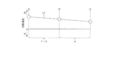
- FIG. 3 is an explanatory diagram of a method of calculating the sun gear rotation speed using the relationship of the collinear chart.
- FIG. 4 is a flowchart showing an example of control according to the second embodiment.
- FIG. 5 is a flowchart showing an execution procedure of various controls using the rotation speed of the primary pulley.
- FIG. 6 is a flowchart showing an example of control according to the third embodiment.
- FIG. 7 is a flowchart showing a modified example of the control of the third embodiment.
- FIG. 8 is an explanatory diagram of the rotation speed detection structure of the ring gear rotation speed sensor.
- FIG. 1 is a diagram showing a main part of a vehicle.
- the vehicle includes an engine ENG, a continuously variable transmission TM, and drive wheels DW.
- the engine ENG constitutes a drive source for running the vehicle.
- the continuously variable transmission TM is a belt type continuously variable transmission, and includes a torque converter TC, a forward/reverse switching mechanism SWM, and a variator VA.
- the power of the engine ENG is transmitted to the drive wheels DW via the torque converter TC, the forward/reverse switching mechanism SWM, and the variator VA.
- the torque converter TC, the forward/reverse switching mechanism SWM, and the variator VA are provided in the power transmission path that connects the engine ENG and the drive wheels DW.
- the torque converter TC transmits power via fluid.
- the power transmission efficiency is increased by engaging the lockup clutch LU.
- the forward/reverse switching mechanism SWM is provided in the power transmission path connecting the engine ENG and the variator VA.
- the forward/reverse switching mechanism SWM switches the forward/backward movement of the vehicle by switching the rotation direction of the input rotation.
- the forward/reverse switching mechanism SWM includes a forward clutch FWD/C that is engaged when the D range, that is, the forward range is selected, and a reverse brake REV/B that is engaged when the R range, that is, the reverse range is selected.
- the continuously variable transmission TM enters the neutral state, that is, the power cutoff state.
- the forward/reverse switching mechanism SWM has a forward clutch FWD/C and a reverse brake REV/B, and a planetary gear mechanism PGM.
- the planetary gear mechanism PGM is a double pinion type planetary gear mechanism, and has a plurality of rotating elements, namely, a sun gear S, a carrier C, a ring gear R, a first planetary pinion P1, and a second planetary pinion P2.
- the sun gear S is connected to the input shaft of the forward/reverse switching mechanism SWM. That is, in the forward/reverse switching mechanism SWM, the input is set to the sun gear S.
- the first planetary pinion P1 meshes with the sun gear S
- the second planetary pinion P2 meshes with the first planetary pinion P1.
- the carrier C is coupled to the output shaft of the forward/reverse switching mechanism SWM. That is, the output is set to the carrier C in the forward/reverse switching mechanism SWM.
- the carrier C rotatably supports the first planetary pinion P1 and the second planetary pinion P2.
- the ring gear R meshes with the second planetary pinion P2.
- the ring gear R is provided with a reverse brake REV/B, and the ring gear R is fixed to the fixing member FM of the forward/reverse switching mechanism SWM by the reverse brake REV/B.
- the fixing member FM is, for example, the case of the forward/reverse switching mechanism SWM.
- a ring gear rotation speed sensor 3 that detects the rotation speed Nr of the ring gear R is provided.
- the variator VA is connected to the forward/reverse switching mechanism SWM.
- the variator VA constitutes a belt type continuously variable transmission mechanism having a primary pulley PRI, a secondary pulley SEC, and a belt BLT wound around the primary pulley PRI and the secondary pulley SEC.
- the primary pressure Ppri is supplied to the primary pulley PRI
- the secondary pressure Psec is supplied to the secondary pulley SEC from a hydraulic control circuit 12 described later.
- the primary pulley PRI is connected to the carrier C.
- the PRI rotation speed sensor 2 is provided for the primary pulley PRI.
- the PRI rotation speed sensor 2 detects the rotation speed Npri of the primary pulley PRI.
- the PRI rotation speed sensor 2 is a pulley that detects the rotation speed of the pulley of the continuously variable transmission TM on the carrier C side of the forward/reverse switching mechanism SWM, that is, on the carrier C side of the sun gear S and the carrier C in the forward/reverse switching mechanism SWM. It constitutes a rotation speed sensor.
- the continuously variable transmission TM further includes a controller 11 and a hydraulic control circuit 12.
- the controller 11 controls the continuously variable transmission TM.
- the controller 11 for example, in addition to the PRI rotation speed sensor 2 and the ring gear rotation speed sensor 3, the engine rotation speed sensor 1 that detects the rotation speed Ne, the operation position of the select lever 20, in other words, the selected range is selected.
- Signals are input from an inhibitor switch 4 that detects a shift position, a vehicle speed sensor 5 that detects a vehicle speed VSP, and the like.
- the controller 11 further includes an accelerator opening sensor that detects the accelerator opening APO, a primary pressure sensor that detects the primary pressure Ppri, a secondary pressure sensor that detects the secondary pressure Psec, and a SEC that detects the rotation speed Nsec of the secondary pulley SEC. Signals from a rotation speed sensor, an oil temperature sensor that detects the oil temperature T OIL of the continuously variable transmission TM, and the like are also input.
- the controller 11 controls the continuously variable transmission TM based on these signals. Specifically, the controller 11 controls the hydraulic control circuit 12 based on these signals.
- the hydraulic control circuit 12 performs hydraulic control of the lockup clutch LU, the forward clutch FWD/C, the reverse brake REV/B, the primary pulley PRI, the secondary pulley SEC, etc. based on the instruction from the controller 11.
- Oil is supplied to the hydraulic control circuit 12 from, for example, an oil pump driven by the power of the engine ENG. Signals from sensors and switches may be input to the controller 11 via another controller such as a controller for controlling the engine ENG.
- the ring gear rotation speed sensor 3 is provided, the turbine rotation speed Nt is acquired by the following control performed by the controller 11, and various controls are performed.
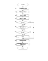
- FIG. 2 is a flowchart showing an example of control performed by the controller 11 in the present embodiment.
- the controller 11 is configured to have the control unit by being configured to perform the processing of this flowchart.
- the controller 11 acquires the rotation speed Npri based on the signal from the PRI rotation speed sensor 2 in step S1, and acquires the rotation speed Nr based on the signal from the ring gear rotation speed sensor 3 in step S2.
- the controller 11 calculates the rotation speed Ns of the sun gear S based on the rotation speed Nr and the rotation speed Npri in step S3.
- the rotation speed Ns is calculated as described below using the relationship of the alignment chart of the planetary gear mechanism PGM.
- FIG. 3 is an explanatory diagram of a method of calculating the rotation speed Ns using the relationship of the alignment chart.
- the collinear diagram of the planetary gear mechanism PGM is a diagram in which the vertical axis represents the rotational speed and the horizontal axis represents the sun gear S, the ring gear R, and the carrier C of the planetary gear mechanism PGM.
- the distance between the sun gear S and the carrier C shown on the horizontal axis is 1
- the distance ⁇ between the carrier C and the ring gear R is the size obtained by dividing the number of teeth ZS of the sun gear S by the number of teeth ZR of the ring gear R. To be done.
- the rotation speed Nc of the carrier C is equal to the rotation speed Npri. Therefore, according to Equation 1, the rotation speed Ns of the sun gear S can be calculated based on the output of the ring gear rotation speed sensor 3 and the output of the PRI rotation speed sensor 2. Moreover, since the rotation speed Ns is equal to the turbine rotation speed Nt, the turbine rotation speed Nt can be calculated according to Equation 1.
- step S4 the controller 11 executes various controls using the calculated turbine rotation speed Nt.
- Various controls are, for example, engagement of the lockup clutch LU, self-diagnosis, and the like.
- step S4 various controls using the turbine rotation speed Nt are appropriately executed using the calculated turbine rotation speed Nt. After step S4, the process ends once.
- one of the input and the output is set to the sun gear S, and the other of the input and the output is set to the carrier C.
- PRI rotation speed sensor 2 that detects the rotation speed Npri of the primary pulley PRI
- a controller 11 that calculates the rotation speed Ns of the sun gear S based on the output of the ring gear rotation speed sensor 3 and the output of the PRI rotation speed sensor 2. It is configured to have.
- the space around the ring gear R arranged on the outer peripheral side of the forward/reverse switching mechanism SWM is much easier to secure a space than the space around the sun gear S, it is neither input nor output, so to speak, floating.
- the rotation speed Nr of the ring gear R which can be called a member, is intentionally detected. Since the rotation speed Npri is the same as the rotation speed Nc of the carrier C, the PRI rotation speed sensor 2 essential to the variator VA is used to determine the rotation speed Ns of the sun gear S from the relationship of the alignment chart of the planetary gear mechanism PGM. Is calculated.
- the ring gear rotation speed sensor 3 may be provided to obtain the turbine rotation speed Nt, the compact design of the forward/reverse switching mechanism SWM having the above-mentioned input/output relationship is possible. Therefore, the layout flexibility can be improved.
- the controller 11 is configured to perform the control described below. Except for this point, the vehicle is configured similarly to the first embodiment.
- FIG. 4 is a flowchart showing an example of control performed by the controller 11 in the present embodiment.
- the processing of step S11, step S12, step S17, and step S18 is the same as the processing of step S1 to step S4 of the flowchart shown in FIG. Therefore, the processing other than these is mainly described here.
- step S13 the controller 11 acquires the vehicle speed VSP based on the signal from the vehicle speed sensor 5.
- step S14 the controller 11 determines whether the rotation speed Npri is lower than a predetermined value Npri1 (for example, 25 rpm).
- the predetermined value Npri1 is preset as a determination value for determining whether the output accuracy of the PRI rotation speed sensor 2 deteriorates, and it is determined that the output accuracy deteriorates when the rotation speed Npri is equal to or less than the predetermined value Npri1. .. If a positive determination is made in step S14, the process proceeds to step S15. When the rotation speed Npri is the predetermined value Npri1, it may be included in the positive determination in step S14.
- step S15 the controller 11 determines whether the vehicle speed VSP is lower than a predetermined vehicle speed VSP1 (for example, 1 km/h).
- the predetermined vehicle speed VSP1 is preset as a determination value for considering that the vehicle is stopped, and when the vehicle speed VSP is lower than the predetermined vehicle speed VSP1, the vehicle is considered to be stopped. If a positive determination is made in step S15, the process proceeds to step S16. When the vehicle speed VSP is the predetermined vehicle speed VSP1, it may be included in the positive determination in step S14.
- step S16 the controller 11 sets the rotation speed Npri to zero.
- step S16 when the vehicle can be considered to be stopped, the primary pulley PRI is also considered to be stopped, so that the rotation speed Npri is set to zero.
- step S17 When the process of step S17 is performed after step S16, the rotation speed Npri used for calculating the rotation speed Ns is set to zero. Therefore, the deviation of the calculation result due to the deterioration of the output accuracy of the PRI rotation speed sensor 2 is suppressed.
- step S17 the rotation speed Ns of the sun gear S is calculated based on the output of the ring gear rotation speed sensor 3 and the output of the PRI rotation speed sensor 2.
- the rotation speed Npri is also used for various controls other than the calculation of the rotation speed Ns.
- FIG. 5 is a flowchart showing an execution procedure of various controls using the rotation speed Npri. The process of this flowchart is also performed in the vehicle described in the first embodiment.
- step S101 the controller 11 acquires the rotation speed Npri based on the signal from the PRI rotation speed sensor 2.
- step S102 the controller 11 executes various controls such as determination of the gear ratio of the variator VA using the acquired rotation speed Npri.
- various controls using the rotation speed Npri are appropriately executed using the rotation speed Npri acquired based on the signal from the PRI rotation speed sensor 2. That is, when the rotation speed Npri is used for various controls other than the calculation of the rotation speed Ns, the rotation speed Npri is not set to zero.
- the process of this flowchart is temporarily terminated.
- the forward/reverse switching mechanism SWM has the input set to the sun gear S and the output set to the carrier C, and the controller 11 uses the rotation speed Npri of the primary pulley PRI to rotate the sun gear S. Ns is calculated, and when the rotation speed Npri is lower than the predetermined value Npri1 and the vehicle speed VSP is lower than the predetermined vehicle speed VSP1, the rotation speed Npri is set to zero and the rotation speed Ns is calculated.
- the primary pulley PRI is also considered to be stopped, and the rotational speed Ns is calculated, so that the deviation of the calculation result can be suppressed.
- the controller 11 is configured to perform the control described below. Except for this point, the vehicle is configured similarly to the first embodiment.
- FIG. 6 is a flowchart showing an example of control performed by the controller 11 in the present embodiment.
- the processing from step S21 to step S23, step S29, and step S30 is the same as the processing from step S11 to step S13, step S17, and step S18 in the flowchart shown in FIG. Therefore, the processing other than these is mainly described here.
- step S24 the controller 11 acquires the selection range based on the signal from the inhibitor switch 4.
- step S25 the controller 11 determines whether the selected range is the R range. This is because the deterioration of the output accuracy of the ring gear rotation speed sensor 3 occurs in the R range according to the conditions of the next step S26 and step S27. If a positive determination is made in S25, the process proceeds to step S26.
- step S26 the controller 11 determines whether the vehicle speed VSP is equal to or higher than a predetermined vehicle speed VSP1, or whether the rotation speed Npri is equal to or higher than a predetermined value Npri1. In step S26, it is determined whether or not the vehicle is in the deemed stop state and whether or not the output accuracy of the PRI rotation speed sensor 2 is deteriorated. If either determination is affirmative, a positive determination is made in step S26. Then, the process proceeds to step S27. In step S27, an affirmative determination is made even when the vehicle speed VSP is equal to or higher than the predetermined vehicle speed VSP1 and the rotation speed Npri is equal to or higher than the predetermined value Npri1. When the rotation speed Npri is the predetermined value Npri1, it may be included in the negative determination in step S26, and when the vehicle speed VSP is the predetermined vehicle speed VSP1, it may be included in the negative determination in step S26.
- step S27 the controller 11 determines whether the rotation speed Nr of the ring gear R is lower than a predetermined value Nr1 (for example, 25 rpm).
- the predetermined value Nr1 is preset as a determination value for determining whether the output accuracy of the ring gear rotation speed sensor 3 is deteriorated, and it is determined that the output accuracy is deteriorated when the rotation speed Nr is lower than the predetermined value Nr1. To be done. If a positive determination is made in step S27, the process proceeds to step S28. When the rotation speed Nr is the predetermined value Nr1, it may be included in the positive determination in step S27.
- step S28 the controller 11 sets the rotation speed Nr to zero.
- the deviation of the calculation result due to the deterioration of the output accuracy of the ring gear rotation speed sensor 3 is suppressed.
- the forward/reverse switching mechanism SWM has the input set to the sun gear S and the output set to the carrier C, and the controller 11 uses the rotation speed Nr of the ring gear R to rotate the sun gear S.
- the vehicle speed VSP is equal to or higher than the predetermined vehicle speed VSP1 or the rotation speed Npri is equal to or higher than the predetermined value Npri1, and the rotation speed Nr is lower than the predetermined value Nr1, the rotation speed Nr. Is set to zero and the rotation speed Ns is calculated.
- FIG. 7 shows a similar modification applied to the flowchart shown in FIG.
- step S25, step S27, and step S28 are added after the negative determination in step S14 and the negative determination in step S15. Then, if the affirmative determination is made in steps S25 and S27, the process proceeds to step S28 and further to step S17, and if the negative determination is made in any of the steps S25 and S27, the process proceeds to step S17.
- FIG. 8 is an explanatory diagram of a rotation speed detection structure of the ring gear rotation speed sensor 3.
- a rotational speed detection structure will be described using a forward/reverse switching mechanism SWM′ having a single pinion type planetary gear mechanism PGM′. The same structure can be applied to the forward/reverse switching mechanism SWM.
- the respective components of the forward/reverse switching mechanism SWM′ corresponding to the respective components of the forward/reverse switching mechanism SWM are indicated by reference numerals with dashes.
- the forward/reverse switching mechanism SWM′ includes a planetary gear mechanism PGM′ having a sun gear S′, a carrier C′, and a ring gear R′, a forward clutch FWD/C′, a reverse brake REV/B′, and a clutch drum DR.
- the clutch drum DR corresponds to a tubular portion and has a spline SP into which a plurality of clutch plates of a forward clutch FWD/C′ and a reverse brake REV/B′, which are multi-plate clutches, are fitted.
- the spline SP can be configured so that the clutch plate of at least one of the forward clutch FWD/C' and the reverse brake REV/B' is engaged.
- the spline SP is formed by pressing. Therefore, in the portion of the clutch drum DR where the spline SP is provided, the spline SP is formed not only inside the clutch drum DR but also outside the clutch drum DR.
- the ring gear rotation speed sensor 3 is provided so as to detect the rotation speed Nr of the ring gear R′ by using such a spline SP as a detected portion.
- the ring gear rotation speed sensor 3 is arranged in a region adjacent to the reverse brake REV/B' in the axial direction and in a region opposite to the forward clutch FWD/C' across the clutch drum DR.
- the region may be a region adjacent to the reverse brake REV/B′ in the axial direction or a region opposite to the forward clutch FWD/C′ with the clutch drum DR interposed therebetween.
- the forward/reverse switching mechanism SWM may have a configuration in which the input is set to the carrier C and the output is set to the sun gear S.
- the pulley rotation speed sensor 2 constitutes a pulley rotation speed sensor
- the pulley rotation speed sensor may be composed of, for example, an SEC rotation speed sensor.
- the rotation speed Nc of the carrier C can be calculated using the gear ratio of the variator VA.
- the planetary gear mechanism PGM is the double pinion type planetary gear mechanism.
- the planetary gear mechanism PGM may be, for example, a single-pinion type planetary gear mechanism.
- the forward clutch FWD/C connects the carrier C and the ring gear R
- the forward clutch FWD/C may be configured to connect the sun gear S and the carrier C or the sun gear S and the ring gear R.
- the planetary gear mechanism PGM is configured by a single-pinion type planetary gear mechanism.
- the controller 11 may be, for example, a plurality of controllers configured to perform processing in a distributed manner, or may be configured to include a control unit by such a plurality of controllers.
Landscapes
- Engineering & Computer Science (AREA)
- General Engineering & Computer Science (AREA)
- Mechanical Engineering (AREA)
- Control Of Transmission Device (AREA)
Abstract
車両は、入力及び出力のうちの一方がサンギアに設定されるとともに、入力及び出力のうちの他方がキャリアに設定された前後進切替機構と、前後進切替機構と接続されたバリエータとを有する車両であって、前後進切替機構のリングギアの回転速度を検出するリングギア回転速度センサと、前後進切替機構のキャリア側にあるバリエータのプライマリプーリの回転速度を検出するPRI回転速度センサと、リングギア回転速度センサの出力とPRI回転速度センサの出力とに基づきサンギアの回転速度を演算するコントローラとを備える構成とされる。
Description
本発明は、車両及び車両の制御方法に関する。
JP2005-273769Aには、リングギアを入力としサンギアを出力とする遊星歯車機構を有する前後進切替機構が開示されている。この場合、リングギアの回転速度は、トルクコンバータのタービン回転速度と同じである。このため、JP2005-273769Aでは、リングギアの回転速度をセンサにより検出することで、タービン回転速度を直接的に取得可能な構成となっており、リングギアの周囲はセンサ取付スペースも確保し易くなっている。
前後進切替機構においては、サンギアを入力としキャリアを出力とすることが考えられる。この場合、サンギア及び前後進切替機構の入力軸周りには多くの部材が存在しており、特にコンパクト化を追求する近年においてはその集積度(密集度)が非常に高くなっている。このため、タービン回転速度を直接的に取得するためのセンサの取付スペースをサンギア及び前後進切替機構の入力軸周りに無理に作ろうとするとコンパクト化の妨げとなる虞がある。
本発明はこのような課題に鑑みてなされたもので、タービン回転速度を取得するにあたり、サンギアを入力としキャリアを出力とする前後進切替機構のコンパクトな設計を可能にし、以てレイアウト自由度を向上させることを目的とする。
本発明のある態様の車両は、入力及び出力のうちの一方がサンギアに設定されるとともに、入力及び出力のうちの他方がキャリアに設定された前後進切替機構と、前記前後進切替機構と接続された無段変速機構とを有する車両であって、前記前後進切替機構のリングギアの回転速度を検出するリングギア回転速度センサと、前記前後進切替機構の前記キャリア側にある前記無段変速機構のプーリの回転速度を検出するプーリ回転速度センサと、前記リングギア回転速度センサの出力と前記プーリ回転速度センサの出力とに基づき前記サンギアの回転速度を演算する制御部と、を有する。
本発明の別の態様によれば、上記車両に対応する車両の制御方法が提供される。
ここで、前後進切替機構の外周側に配置されるリングギアの周囲は、サンギア周囲と比較して遥かにスペースを確保し易い。このためこれらの態様では、入力とも出力ともされないいわば浮遊部材と言えるリングギアの回転速度を敢えて検出する。そして、無段変速機構のプーリ回転速度はキャリアの回転速度と同じか比例することから、無段変速機構に必須のプーリ回転速度センサを利用して、遊星歯車機構の共線図の関係からサンギアの回転速度を演算する。
このような態様によれば、タービン回転速度を取得するにあたり、リングギア回転速度センサを設ければよいので、上記のような入出力関係を有する前後進切替機構のコンパクトな設計が可能になり、レイアウト自由度を向上させることができる。
以下、添付図面を参照しながら本発明の実施形態について説明する。
(第1実施形態)
図1は、車両の要部を示す図である。車両は、エンジンENGと、無段変速機TMと、駆動輪DWと、を備える。
図1は、車両の要部を示す図である。車両は、エンジンENGと、無段変速機TMと、駆動輪DWと、を備える。
エンジンENGは、車両の走行用駆動源を構成する。無段変速機TMは、ベルト式の無段変速機であり、トルクコンバータTCと、前後進切替機構SWMと、バリエータVAとを有する。エンジンENGの動力は、トルクコンバータTC、前後進切替機構SWM、バリエータVAを介して駆動輪DWへと伝達される。換言すれば、トルクコンバータTC、前後進切替機構SWM、バリエータVAは、エンジンENGと駆動輪DWとを結ぶ動力伝達経路に設けられる。
トルクコンバータTCは、流体を介して動力を伝達する。トルクコンバータTCでは、ロックアップクラッチLUを締結することで、動力伝達効率が高められる。
前後進切替機構SWMは、エンジンENGとバリエータVAとを結ぶ動力伝達経路に設けられる。前後進切替機構SWMは、入力される回転の回転方向を切り替えることで車両の前後進を切り替える。前後進切替機構SWMは、Dレンジつまり前進レンジ選択の際に係合される前進クラッチFWD/Cと、Rレンジつまりリバースレンジ選択の際に係合される後退ブレーキREV/Bとを備える。前進クラッチFWD/C及び後退ブレーキREV/Bを解放すると、無段変速機TMはニュートラル状態つまり動力遮断状態になる。
前後進切替機構SWMは、前進クラッチFWD/C及び後退ブレーキREV/Bのほか、遊星歯車機構PGMを有して構成される。遊星歯車機構PGMは、ダブルピニオン式の遊星歯車機構であり、複数の回転要素であるサンギアS、キャリアC、リングギアRと、第1プラネタリピニオンP1と、第2プラネタリピニオンP2とを有する。
サンギアSは、前後進切替機構SWMの入力軸に結合される。つまり、前後進切替機構SWMにおいて、入力はサンギアSに設定される。第1プラネタリピニオンP1は、サンギアSと噛み合い、第2プラネタリピニオンP2は、第1プラネタリピニオンP1と噛み合う。キャリアCは、前後進切替機構SWMの出力軸に結合される。つまり、前後進切替機構SWMにおいて、出力はキャリアCに設定される。キャリアCは、第1プラネタリピニオンP1と第2プラネタリピニオンP2とを回転可能に支持する。
リングギアRは、第2プラネタリピニオンP2と噛み合う。リングギアRには後進ブレーキREV/Bが設けられ、リングギアRは、後進ブレーキREV/Bによって前後進切替機構SWMの固定部材FMに固定される。固定部材FMは例えば、前後進切替機構SWMのケースである。リングギアRに対しては、リングギアRの回転速度Nrを検出するリングギア回転速度センサ3が設けられる。
バリエータVAは、前後進切替機構SWMに接続される。バリエータVAは、プライマリプーリPRIと、セカンダリプーリSECと、プライマリプーリPRI及びセカンダリプーリSECに巻き掛けられたベルトBLTとを有するベルト式無段変速機構を構成する。プライマリプーリPRIにはプライマリ圧Ppriが、セカンダリプーリSECにはセカンダリ圧Psecが、後述する油圧制御回路12からそれぞれ供給される。
プライマリプーリPRIは、キャリアCと連結する。プライマリプーリPRIに対しては、PRI回転速度センサ2が設けられる。PRI回転速度センサ2は、プライマリプーリPRIの回転速度Npriを検出する。PRI回転速度センサ2は、前後進切替機構SWMのキャリアC側、つまり前後進切替機構SWMにおいてサンギアS及びキャリアCのうちキャリアC側にある無段変速機TMのプーリの回転速度を検出するプーリ回転速度センサを構成する。
無段変速機TMは、コントローラ11と油圧制御回路12とをさらに有する。
コントローラ11は、無段変速機TMを制御する。コントローラ11には例えば、PRI回転速度センサ2、リングギア回転速度センサ3のほか、回転速度Neを検出するエンジン回転速度センサ1、セレクトレバー20の操作位置、換言すれば選択レンジを含む選択されたシフトポジションを検出するインヒビタスイッチ4、車速VSPを検出する車速センサ5等からの信号が入力される。
コントローラ11にはこのほか、アクセル開度APOを検出するアクセル開度センサ、プライマリ圧Ppriを検出するプライマリ圧センサ、セカンダリ圧Psecを検出するセカンダリ圧センサ、セカンダリプーリSECの回転速度Nsecを検出するSEC回転速度センサ、無段変速機TMの油温TOILを検出する油温センサ等からの信号も入力される。
コントローラ11は、これらの信号に基づき無段変速機TMを制御する。具体的にはコントローラ11は、これらの信号に基づき油圧制御回路12を制御する。油圧制御回路12は、コントローラ11からの指示に基づき、ロックアップクラッチLU、前進クラッチFWD/C、後退ブレーキREV/B、プライマリプーリPRI、セカンダリプーリSEC等の油圧制御を行う。油圧制御回路12には例えば、エンジンENGの動力により駆動されるオイルポンプから油が供給される。コントローラ11には、エンジンENG制御用のコントローラなど、他のコントローラを介してセンサ、スイッチからの信号が入力されてもよい。
ところで、サンギアS及び前後進切替機構SWMの入力軸周りには多くの部材が存在しており、特にコンパクト化を追求する近年においてはその集積度(密集度)が非常に高くなっている。このため、トルクコンバータTCのタービン回転速度Ntを直接的に取得するためのセンサの取付スペースをサンギアS及び前後進切替機構SWMの入力軸周りに無理に作ろうとするとコンパクト化の妨げとなることが懸念される。
このような事情に鑑み、本実施形態ではリングギア回転速度センサ3を設け、コントローラ11が行う次の制御によりタービン回転速度Ntを取得し、各種制御を行う。
図2は、本実施形態でコントローラ11が行う制御の一例をフローチャートで示す図である。コントローラ11は、本フローチャートの処理を行うように構成されることで、制御部を有した構成とされる。
コントローラ11は、ステップS1でPRI回転速度センサ2からの信号に基づき、回転速度Npriを取得し、ステップS2でリングギア回転速度センサ3からの信号に基づき、回転速度Nrを取得する。
コントローラ11は、ステップS3で回転速度Nrと回転速度Npriとに基づき、サンギアSの回転速度Nsを演算する。回転速度Nsは、遊星歯車機構PGMの共線図の関係を用いて次に説明するように演算される。
図3は、共線図の関係を利用した回転速度Nsの演算方法の説明図である。遊星歯車機構PGMの共線図は、縦軸に回転速度、横軸に遊星歯車機構PGMのサンギアS、リングギアR、キャリアCを配置した図である。横軸上に示されるサンギアSとキャリアCとの距離を1とした場合、キャリアCとリングギアRとの距離αはサンギアSの歯数ZSをリングギアRの歯数ZRで割った大きさとされる。
共線図においては、共線L1上に斜辺を有し、底辺が1及びαとなる大小2つの直角三角形の相似関係に基づき、次の数1が得られる。
[数1]
Ns=[Nr-Nc(1-α)]/α
[数1]
Ns=[Nr-Nc(1-α)]/α
従って、サンギアSの回転速度Nsは、数1により演算することができる。
本実施形態では、キャリアCの回転速度Ncは回転速度Npriと等しい。このため、数1によれば、リングギア回転速度センサ3の出力とPRI回転速度センサ2の出力とに基づきサンギアSの回転速度Nsを演算できる。また、回転速度Nsはタービン回転速度Ntと等しいので、数1によれば、タービン回転速度Ntを演算できる。
図2に戻り、ステップS4で、コントローラ11は、演算されたタービン回転速度Ntを用いて各種制御を実行する。各種制御は例えば、ロックアップクラッチLUの締結や自己診断等である。ステップS4では、タービン回転速度Ntを用いる各種制御が、演算されたタービン回転速度Ntを用いて適宜実行される。ステップS4の後には処理は一旦終了する。
次に、本実施形態の主な作用効果について説明する。
本実施形態における車両は、入力及び出力のうちの一方がサンギアSに設定されるとともに、入力及び出力のうちの他方がキャリアCに設定された前後進切替機構SWMと、前後進切替機構SWMと接続されたバリエータVAとを有する車両であって、前後進切替機構SWMのリングギアRの回転速度Nrを検出するリングギア回転速度センサ3と、前後進切替機構SWMのキャリアC側にあるバリエータVAのプライマリプーリPRIの回転速度Npriを検出するPRI回転速度センサ2と、リングギア回転速度センサ3の出力とPRI回転速度センサ2の出力とに基づきサンギアSの回転速度Nsを演算するコントローラ11とを備える構成とされる。
このような構成では、前後進切替機構SWMの外周側に配置されるリングギアRの周囲は、サンギアS周囲と比較して遥かにスペースを確保し易いことに鑑み、入力とも出力ともされないいわば浮遊部材と言えるリングギアRの回転速度Nrを敢えて検出する。そして、回転速度NpriはキャリアCの回転速度Ncと同じであることから、バリエータVAに必須のPRI回転速度センサ2を利用し、遊星歯車機構PGMの共線図の関係からサンギアSの回転速度Nsを演算する。
このような構成によれば、タービン回転速度Ntを取得するにあたり、リングギア回転速度センサ3を設ければよいので、上記のような入出力関係を有する前後進切替機構SWMのコンパクトな設計が可能になり、レイアウト自由度を向上させることができる。
(第2実施形態)
本実施形態では、コントローラ11が以下で説明する制御を行うように構成される。この点以外、車両は、第1実施形態と同様に構成される。
本実施形態では、コントローラ11が以下で説明する制御を行うように構成される。この点以外、車両は、第1実施形態と同様に構成される。
図4は、本実施形態でコントローラ11が行う制御の一例をフローチャートで示す図である。ステップS11、ステップS12、ステップS17及びステップS18の処理は、図2に示すフローチャートのステップS1からステップS4の処理と同じである。このため、ここでは主にこれら以外の処理について説明する。
ステップS13で、コントローラ11は、車速センサ5からの信号に基づき、車速VSPを取得する。
ステップS14で、コントローラ11は、回転速度Npriが所定値Npri1(例えば25rpm)よりも低いか否かを判定する。所定値Npri1は、PRI回転速度センサ2の出力精度が悪化するか否かを判定するための判定値として予め設定され、回転速度Npriが所定値Npri1以下の場合に出力精度が悪化すると判定される。ステップS14で肯定判定であれば、処理はステップS15に進む。回転速度Npriが所定値Npri1の場合は、ステップS14の肯定判定に含まれてもよい。
ステップS15で、コントローラ11は、車速VSPが所定車速VSP1(例えば1km/h)よりも低いか否かを判定する。所定車速VSP1は、車両が停止しているとみなすための判定値として予め設定され、車速VSPが所定車速VSP1よりも低い場合に車両が停止しているとみなされる。ステップS15で肯定判定であれば、処理はステップS16に進む。車速VSPが所定車速VSP1の場合は、ステップS14の肯定判定に含まれてもよい。
ステップS16で、コントローラ11は、回転速度Npriをゼロに設定する。ステップS16では、車両が停止しているとみなせる場合にはプライマリプーリPRIも停止しているとみなすことにより、回転速度Npriがゼロに設定される。
ステップS16に続いてステップS17の処理が行われた場合、回転速度Nsの演算に用いられる回転速度Npriがゼロに設定される。このため、PRI回転速度センサ2の出力精度の悪化による演算結果のずれが抑制される。
ステップS14、ステップS15で否定判定の場合も、処理はステップS17に進む。この場合は、第1実施形態で前述したように、リングギア回転速度センサ3の出力とPRI回転速度センサ2の出力とに基づきサンギアSの回転速度Nsが演算される。
回転速度Npriは、回転速度Nsの演算以外の各種制御にも用いられる。
図5は、回転速度Npriを用いた各種制御の実行手順をフローチャートで示す図である。なお、本フローチャートの処理は、第1実施形態で前述した車両でも行われる。
ステップS101で、コントローラ11は、PRI回転速度センサ2からの信号に基づき回転速度Npriを取得する。
ステップS102で、コントローラ11は、取得された回転速度Npriを用いて、バリエータVAの変速比の決定等の各種制御を実行する。ステップS102では、回転速度Npriを用いる各種制御が、PRI回転速度センサ2からの信号に基づき取得された回転速度Npriを用いて適宜実行される。つまり、回転速度Nsの演算以外の各種制御に回転速度Npriが用いられる場合、回転速度Npriはゼロに設定されない。ステップS102の後には、本フローチャートの処理は一旦終了する。
次に、本実施形態の主な作用効果について説明する。
本実施形態において、前後進切替機構SWMは、入力がサンギアSに設定されるとともに出力がキャリアCに設定されており、コントローラ11は、プライマリプーリPRIの回転速度Npriを用いてサンギアSの回転速度Nsを演算し、回転速度Npriが所定値Npri1よりも低く且つ車速VSPが所定車速VSP1よりも低い場合には、回転速度Npriをゼロに設定して、回転速度Nsを演算する。
このような構成によれば、車両が停止しているとみなせる場合にプライマリプーリPRIも停止しているとみなして回転速度Nsの演算を行うことで、演算結果のずれを抑制できる。
(第3実施形態)
本実施形態では、コントローラ11が以下で説明する制御を行うように構成される。この点以外、車両は、第1実施形態と同様に構成される。
本実施形態では、コントローラ11が以下で説明する制御を行うように構成される。この点以外、車両は、第1実施形態と同様に構成される。
図6は、本実施形態でコントローラ11が行う制御の一例をフローチャートで示す図である。ステップS21からステップS23、ステップS29、ステップS30の処理は、図4に示すフローチャートのステップS11からステップS13、ステップS17、ステップS18の処理と同じである。このため、ここでは主にこれら以外の処理について説明する。
ステップS24で、コントローラ11は、インヒビタスイッチ4からの信号に基づき選択レンジを取得する。
ステップS25で、コントローラ11は、選択レンジがRレンジか否かを判定する。これは、リングギア回転速度センサ3の出力精度の悪化が、次のステップS26及びステップS27の条件に応じて、Rレンジのときに発生することによる。S25で肯定判定であれば、処理はステップS26に進む。
ステップS26で、コントローラ11は、車速VSPが所定車速VSP1以上か否か、又は回転速度Npriが所定値Npri1以上か否かを判定する。ステップS26では、車両がみなし停止状態でないか否かと、PRI回転速度センサ2の出力精度が悪化していないか否かが判定され、いずれかの判定が肯定判定であれば、ステップS26で肯定判定されて、処理はステップS27に進む。ステップS27では、車速VSPが所定車速VSP1以上、且つ回転速度Npriが所定値Npri1以上の場合も肯定判定される。回転速度Npriが所定値Npri1の場合は、ステップS26の否定判定に含まれてもよく、また、車速VSPが所定車速VSP1の場合は、ステップS26の否定判定に含まれてもよい。
ステップS27で、コントローラ11は、リングギアRの回転速度Nrが所定値Nr1(例えば、25rpm)よりも低いか否かを判定する。所定値Nr1は、リングギア回転速度センサ3の出力精度が悪化するか否かを判定するための判定値として予め設定され、回転速度Nrが所定値Nr1よりも低い場合に出力精度が悪化すると判定される。ステップS27で肯定判定であれば、処理はステップS28に進む。回転速度Nrが所定値Nr1の場合は、ステップS27の肯定判定に含まれてもよい。
ステップS28で、コントローラ11は、回転速度Nrをゼロに設定する。これにより、次のステップS29で回転速度Nsを演算する際に、リングギア回転速度センサ3の出力精度の悪化による演算結果のずれが抑制される。ステップS25、ステップS26、ステップS27のいずれかで否定判定の場合は、ステップS28の処理は行われず、処理はステップS29に進む。
次に、本実施形態の主な作用効果について説明する。
本実施形態において、前後進切替機構SWMは、入力がサンギアSに設定されるとともに出力がキャリアCに設定されており、コントローラ11は、リングギアRの回転速度Nrを用いてサンギアSの回転速度Nsを演算し、選択レンジがRレンジであり、車速VSPが所定車速VSP1以上又は回転速度Npriが所定値Npri1以上であり、且つ回転速度Nrが所定値Nr1よりも低い場合には、回転速度Nrをゼロに設定して、回転速度Nsを演算する。
このような構成によれば、回転速度Nsを演算する際に、リングギア回転速度センサ3の出力精度の悪化による演算結果のずれを抑制できる。
同様の変更は、第2実施形態における車両に適用することもできる。この場合のフローチャートを図7に示す。図7は、図4に示すフローチャートに同様の変更を適用したものである。ステップS14又はステップS15で否定判定の場合、回転速度Npriが所定値Npri1以上という条件、及び車速VSPが所定車速VSP1以上という条件のうち少なくともいずれかが成立していることになる。
このため、図7に示すフローチャートでは、ステップS14の否定判定とステップS15の否定判定とに続いて、ステップS25、ステップS27、ステップS28が追加されている。そして、ステップS25及びステップS27で肯定判定であれば、処理はステップS28さらにはステップS17に進み、ステップS25及びステップS27のうちいずれかで否定判定であれば、処理はステップS17に進む。
このように構成すれば、PRI回転速度センサ2及びリングギア回転速度センサ3の両出力精度の悪化に対処することができる。
(第4実施形態)
本実施形態では、リングギア回転速度センサ3の回転速度検出構造について説明する。本実施形態の取付構造は、上述した各実施形態の車両に適用することができる。
本実施形態では、リングギア回転速度センサ3の回転速度検出構造について説明する。本実施形態の取付構造は、上述した各実施形態の車両に適用することができる。
図8は、リングギア回転速度センサ3の回転速度検出構造の説明図である。図8では、シングルピニオン式の遊星歯車機構PGM´を有する前後進切替機構SWM´を用いて回転速度検出構造を説明する。同様の構造は、前後進切替機構SWMにも適用することができる。図8では、前後進切替機構SWMの各構成に対応する前後進切替機構SWM´の各構成をダッシュ付きの符号で示す。
前後進切替機構SWM´は、サンギアS´、キャリアC´及びリングギアR´を有する遊星歯車機構PGM´のほか、フォワードクラッチFWD/C´、リバースブレーキREV/B´、クラッチドラムDRを備える。クラッチドラムDRは、筒状部に相当し、多板式クラッチであるフォワードクラッチFWD/C´及びリバースブレーキREV/B´の複数のクラッチプレートが嵌合するスプラインSPを有する。スプラインSPは、フォワードクラッチFWD/C´及びリバースブレーキREV/B´のうち少なくともいずれかの締結要素のクラッチプレートが嵌合するように構成することができる。
スプラインSPはプレス加工により形成されている。このため、クラッチドラムDRのうちスプラインSPが設けられた部分には、クラッチドラムDRの内側だけでなく外側にもスプラインSPが形成されている。リングギア回転速度センサ3は、このようなスプラインSPを被検出部としてリングギアR´の回転速度Nrを検出するように設けられる。
リングギア回転速度センサ3は、リバースブレーキREV/B´の軸方向隣の領域且つクラッチドラムDRを挟んでフォワードクラッチFWD/C´とは反対側の領域に配置される。当該領域は、リバースブレーキREV/B´の軸方向隣の領域、又はクラッチドラムDRを挟んでフォワードクラッチFWD/C´と反対側の領域とされてもよい。
上記領域にはスペースを確保し易い。このため本実施形態によれば、上記領域に隣接する部分のスプラインSPを被検出部とすることにより、前後進切替機構SWMのコンパクト化に寄与することができる。
以上、本発明の実施形態について説明したが、上記実施形態は本発明の適用例の一部を示したに過ぎず、本発明の技術的範囲を上記実施形態の具体的構成に限定する趣旨ではない。
上述した実施形態では、前後進切替機構SWMにおいて、入力がサンギアSに設定されるとともに出力がキャリアCに設定される場合について説明した。しかしながら、前後進切替機構SWMは、入力がキャリアCに設定されるとともに出力がサンギアSに設定された構成であってもよい。
上述した実施形態では、PRI回転速度センサ2がプーリ回転速度センサを構成する場合について説明した。しかしながら、プーリ回転速度センサは例えば、SEC回転速度センサにより構成されてもよい。この場合、バリエータVAの変速比を用いてキャリアCの回転速度Ncを演算することができる。
上述した実施形態では、遊星歯車機構PGMがダブルピニオン式の遊星歯車機構である場合について説明した。しかしながら、遊星歯車機構PGMは例えば、シングルピニオン式の遊星歯車機構であってもよい。
上述した実施形態では、前進クラッチFWD/CがキャリアCとリングギアRを接続する場合について説明した。しかしながら、前進クラッチFWD/Cは、サンギアSとキャリアC、或いはサンギアSとリングギアRを接続するように構成されてもよい。遊星歯車機構PGMをシングルピニオン式の遊星歯車機構で構成した場合も同様である。
コントローラ11は例えば、処理を分散させて行うように構成された複数のコントローラであってもよく、このような複数のコントローラによって制御部を有した構成とされてもよい。
本願は2018年12月14日に日本国特許庁に出願された特願2018-234838に基づく優先権を主張し、この出願のすべての内容は参照により本明細書に組み込まれる。
Claims (5)
- 入力及び出力のうちの一方がサンギアに設定されるとともに、入力及び出力のうちの他方がキャリアに設定された前後進切替機構と、前記前後進切替機構と接続された無段変速機構とを有する車両であって、
前記前後進切替機構のリングギアの回転速度を検出するリングギア回転速度センサと、
前記前後進切替機構の前記キャリア側にある前記無段変速機構のプーリの回転速度を検出するプーリ回転速度センサと、
前記リングギア回転速度センサの出力と前記プーリ回転速度センサの出力とに基づき前記サンギアの回転速度を演算する制御部と、
を有する車両。 - 請求項1に記載の車両であって、
前記前後進切替機構は、入力が前記サンギアに設定されるとともに出力が前記キャリアに設定され、
前記制御部は、前記プーリの前記回転速度を用いて前記サンギアの前記回転速度を演算し、前記プーリの前記回転速度が所定値よりも低く且つ車速が所定車速よりも低い場合には、前記プーリの前記回転速度をゼロに設定して、前記サンギアの前記回転速度を演算する、
車両。 - 請求項1に記載の車両であって、
前記前後進切替機構は、入力が前記サンギアに設定されるとともに出力が前記キャリアに設定され、
前記制御部は、前記リングギアの前記回転速度を用いて前記サンギアの前記回転速度を演算し、選択レンジがRレンジであり、車速が所定車速よりも高いか又は前記プーリの前記回転速度が所定値よりも高く、且つ前記リングギアの前記回転速度が所定値よりも低い場合には、前記リングギアの前記回転速度をゼロに設定して、前記サンギアの前記回転速度を演算する、
車両。 - 請求項1に記載の車両であって、
前記前後進切替機構はスプラインを有する筒状部を有し、
前記スプラインに前記前後進切替機構の締結要素のプレートが嵌合していると共に前記スプラインを前記リングギア回転速度センサの被検出部とする、
車両。 - 入力及び出力のうちの一方がサンギアに設定されるとともに、入力及び出力のうちの他方がキャリアに設定された前後進切替機構と、前記前後進切替機構と接続された無段変速機構とを有する車両の制御方法であって、
前記前後進切替機構のリングギアの回転速度を検出することと、
前記前後進切替機構の前記キャリア側にある前記無段変速機構のプーリの回転速度を検出することと、
検出された前記リングギアの前記回転速度と検出された前記プーリの前記回転速度とに基づき前記サンギアの回転速度を演算することと、
を含む車両の制御方法。
Priority Applications (1)
| Application Number | Priority Date | Filing Date | Title |
|---|---|---|---|
| JP2020559879A JP7112513B2 (ja) | 2018-12-14 | 2019-11-18 | 車両及び車両の制御方法 |
Applications Claiming Priority (2)
| Application Number | Priority Date | Filing Date | Title |
|---|---|---|---|
| JP2018-234838 | 2018-12-14 | ||
| JP2018234838 | 2018-12-14 |
Publications (1)
| Publication Number | Publication Date |
|---|---|
| WO2020121743A1 true WO2020121743A1 (ja) | 2020-06-18 |
Family
ID=71076320
Family Applications (1)
| Application Number | Title | Priority Date | Filing Date |
|---|---|---|---|
| PCT/JP2019/045114 Ceased WO2020121743A1 (ja) | 2018-12-14 | 2019-11-18 | 車両及び車両の制御方法 |
Country Status (2)
| Country | Link |
|---|---|
| JP (1) | JP7112513B2 (ja) |
| WO (1) | WO2020121743A1 (ja) |
Citations (5)
| Publication number | Priority date | Publication date | Assignee | Title |
|---|---|---|---|---|
| JPH09133203A (ja) * | 1995-11-06 | 1997-05-20 | Hitachi Ltd | 自動変速機のタービン回転数の検出方法および装置 |
| JP2003130209A (ja) * | 2001-10-24 | 2003-05-08 | Aisin Aw Co Ltd | 車両のレンジ切り替え装置 |
| JP2005164001A (ja) * | 2003-12-05 | 2005-06-23 | Fuji Heavy Ind Ltd | 動力伝達機構の故障診断装置 |
| JP2009537753A (ja) * | 2006-05-19 | 2009-10-29 | ツェットエフ、フリードリッヒスハーフェン、アクチエンゲゼルシャフト | トランスミッションの主軸の回転数を求める方法及び回転数検出装置を備えたトランスミッション |
| JP2014134275A (ja) * | 2013-01-11 | 2014-07-24 | Toyota Motor Corp | 車両の制御装置 |
-
2019
- 2019-11-18 JP JP2020559879A patent/JP7112513B2/ja active Active
- 2019-11-18 WO PCT/JP2019/045114 patent/WO2020121743A1/ja not_active Ceased
Patent Citations (5)
| Publication number | Priority date | Publication date | Assignee | Title |
|---|---|---|---|---|
| JPH09133203A (ja) * | 1995-11-06 | 1997-05-20 | Hitachi Ltd | 自動変速機のタービン回転数の検出方法および装置 |
| JP2003130209A (ja) * | 2001-10-24 | 2003-05-08 | Aisin Aw Co Ltd | 車両のレンジ切り替え装置 |
| JP2005164001A (ja) * | 2003-12-05 | 2005-06-23 | Fuji Heavy Ind Ltd | 動力伝達機構の故障診断装置 |
| JP2009537753A (ja) * | 2006-05-19 | 2009-10-29 | ツェットエフ、フリードリッヒスハーフェン、アクチエンゲゼルシャフト | トランスミッションの主軸の回転数を求める方法及び回転数検出装置を備えたトランスミッション |
| JP2014134275A (ja) * | 2013-01-11 | 2014-07-24 | Toyota Motor Corp | 車両の制御装置 |
Also Published As
| Publication number | Publication date |
|---|---|
| JPWO2020121743A1 (ja) | 2020-06-18 |
| JP7112513B2 (ja) | 2022-08-03 |
Similar Documents
| Publication | Publication Date | Title |
|---|---|---|
| KR101635302B1 (ko) | 차량용 변속기의 제어 장치 | |
| JP4333784B2 (ja) | 無段変速機の故障判定装置および故障判定方法 | |
| KR101706898B1 (ko) | 무단 변속기 및 그 제어 방법 | |
| JP6622924B2 (ja) | 自動変速機のプーリ推進装置および自動変速機の制御装置 | |
| JP6015852B2 (ja) | 車両の制御装置および方法 | |
| JP2005291111A (ja) | 車両用ベルト式無段変速機の入力トルク制御装置 | |
| JPWO2013088875A1 (ja) | 無段変速機及びその制御方法 | |
| JP2000055177A (ja) | 無段変速機の制御装置 | |
| JP7112513B2 (ja) | 車両及び車両の制御方法 | |
| WO2019239885A1 (ja) | 自動変速機の制御装置 | |
| JP2010053939A (ja) | ベルト式無段変速機 | |
| JP2017036783A (ja) | 動力伝達装置の制御装置 | |
| JP6851699B2 (ja) | 自動変速機のクラッチ滑り診断装置及びクラッチ滑り診断方法 | |
| WO2016152289A1 (ja) | 変速機の制御装置及び変速機の制御方法 | |
| WO2020162148A1 (ja) | ベルト式無段変速機 | |
| JP6913258B2 (ja) | 無段変速機の制御装置および制御方法 | |
| JP6774574B2 (ja) | 車両の制御装置及び車両の制御方法 | |
| JP6310900B2 (ja) | 変速機 | |
| JPH02180358A (ja) | 車両用自動変速機の制御装置 | |
| JP2008196581A (ja) | ベルト式無段変速機の変速制御装置 | |
| JP2004251359A (ja) | 無段変速機の制御装置 | |
| JP4321414B2 (ja) | パワートレインの制御装置 | |
| JP2007100886A (ja) | ベルト式無段変速機 | |
| JP2014224562A (ja) | 自動変速機の制御装置 | |
| JP2007255550A (ja) | 無段変速装置の前後進切換制御装置 |
Legal Events
| Date | Code | Title | Description |
|---|---|---|---|
| 121 | Ep: the epo has been informed by wipo that ep was designated in this application |
Ref document number: 19894420 Country of ref document: EP Kind code of ref document: A1 |
|
| ENP | Entry into the national phase |
Ref document number: 2020559879 Country of ref document: JP Kind code of ref document: A |
|
| NENP | Non-entry into the national phase |
Ref country code: DE |
|
| 122 | Ep: pct application non-entry in european phase |
Ref document number: 19894420 Country of ref document: EP Kind code of ref document: A1 |