WO2020121370A1 - 空調機、制御装置、空調システム、空調制御方法及びプログラム - Google Patents
空調機、制御装置、空調システム、空調制御方法及びプログラム Download PDFInfo
- Publication number
- WO2020121370A1 WO2020121370A1 PCT/JP2018/045275 JP2018045275W WO2020121370A1 WO 2020121370 A1 WO2020121370 A1 WO 2020121370A1 JP 2018045275 W JP2018045275 W JP 2018045275W WO 2020121370 A1 WO2020121370 A1 WO 2020121370A1
- Authority
- WO
- WIPO (PCT)
- Prior art keywords
- user
- biometric data
- air conditioning
- air
- thermal image
- Prior art date
Links
Images


Classifications
-
- F—MECHANICAL ENGINEERING; LIGHTING; HEATING; WEAPONS; BLASTING
- F24—HEATING; RANGES; VENTILATING
- F24F—AIR-CONDITIONING; AIR-HUMIDIFICATION; VENTILATION; USE OF AIR CURRENTS FOR SCREENING
- F24F11/00—Control or safety arrangements
- F24F11/30—Control or safety arrangements for purposes related to the operation of the system, e.g. for safety or monitoring
Definitions
- the present invention relates to an air conditioner, a control device, an air conditioning system, an air conditioning control method, and a program.
- an air conditioner adjusts environmental factors such as indoor temperature, humidity, and airflow to maintain the comfort of people in the room.
- environmental factors such as indoor temperature, humidity, and airflow.
- the sensation (ie, thermal sensation) of the indoor thermal environment varies from individual to individual, it is difficult to properly maintain the comfort of the occupants with air conditioning that depends only on environmental factors. ..
- the present invention has been made to solve the above problems, and an object thereof is to provide an air conditioner or the like for accurately realizing comfortable air conditioning for a user.
- the air conditioner for adjusting indoor air
- a thermal image sensor for acquiring the indoor thermal image
- Biometric data acquisition means worn by a user to acquire the biometric data from a biometric data measuring device that measures biometric data including at least the body temperature of the user
- An air conditioning control means is provided for performing air conditioning control based on the acquired thermal image and the acquired biological data.
- FIG. 3 is a block diagram showing a hardware configuration of a control board included in the indoor unit of the first embodiment.
- Block diagram showing the hardware configuration of the outdoor unit of the first embodiment FIG. 3 is a block diagram showing the hardware configuration of the biological data measuring device according to the first embodiment.
- FIG. 3 is a diagram for explaining clothing amount estimation according to the first embodiment.
- the flowchart which shows the procedure of the air-conditioning control processing in Embodiment 1.
- the figure which shows the whole structure of the air conditioning system which concerns on Embodiment 2 of this invention Block diagram showing the hardware configuration of the cloud server of the second embodiment
- FIG. 1 is a diagram showing an overall configuration of an air conditioning system 1 according to Embodiment 1 of the present invention.
- the air conditioning system 1 is a system that air-conditions a room R in a building, and includes an air conditioner 2 and a biological data measuring device 3 as shown in FIG.
- the air conditioner 2 is an example of the air conditioner according to the present invention.
- the air conditioner 2 includes an indoor unit 4 installed in the room R, an outdoor unit 5 installed outside the room R, and an air conditioning remote controller 6 installed in the room R.
- the indoor unit 4 and the outdoor unit 5 are connected via a communication line 7 and a refrigerant pipe 8 for circulating a refrigerant.
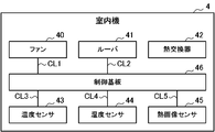
- the indoor unit 4 includes a fan 40, a louver 41, a heat exchanger 42, a temperature sensor 43, a humidity sensor 44, a thermal image sensor 45, and a control board 46.
- the fan 40 is, for example, a sirocco fan, takes in the air in the room R from a suction port (not shown) of the indoor unit 4, and sends out the air that has been heat-exchanged by the heat exchanger 42 from a blowout port (not shown) of the indoor unit 4. ..
- the fan 40 is communicatively connected to the control board 46 via a communication line CL1.
- the rotation speed of the fan 40 that is, the amount of air blown by the fan 40 is adjusted according to a control command from the control board 46.
- the louver 41 adjusts the direction of the air sent to the room R by the fan 40.
- the louver 41 is communicatively connected to the control board 46 via a communication line CL2.
- the angle of the louver 41, that is, the wind direction is adjusted according to a control command from the control board 46.
- the heat exchanger 42 exchanges heat between the air taken in by the fan 40 and the refrigerant from the outdoor unit 5.
- the heat exchanger 42 functions as an evaporator during cooling operation, and functions as a condenser during heating operation.
- the temperature sensor 43 measures the temperature of the air taken in by the fan 40.
- the temperature sensor 43 is communicatively connected to the control board 46 via the communication line CL3.
- the temperature sensor 43 transmits data indicating the measured temperature (hereinafter, referred to as temperature data) to the control board 46.
- the humidity sensor 44 measures the humidity of the air taken in by the fan 40.
- the humidity sensor 44 is communicatively connected to the control board 46 via the communication line CL4.
- the humidity sensor 44 transmits data indicating the measured humidity (hereinafter, referred to as humidity data) to the control board 46 in response to a request from the control board 46.
- the thermal image sensor 45 is an example of the thermal image sensor according to the present invention.
- the thermal image sensor 45 is infrared thermography and acquires a thermal image of the room R.
- the thermal image sensor 45 is communicatively connected to the control board 46 via a communication line CL5.
- the thermal image sensor 45 transmits data indicating the acquired thermal image (hereinafter referred to as thermal image data) to the control board 46.
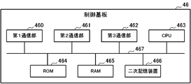
- the control board 46 includes a first communication unit 460, a second communication unit 461, a third communication unit 462, a CPU 463, a ROM 464, a RAM 465, and a secondary storage device 466. .. These components are connected to each other via a bus 467.
- the first communication unit 460 is hardware that communicates with the outdoor unit 5 via the communication line 7.
- the second communication unit 461 is hardware that performs wireless communication such as infrared communication with the air conditioning remote controller 6.
- the third communication unit 462 is hardware that performs wireless communication with the biological data measuring device 3 in accordance with communication standards such as Wi-Fi (registered trademark) and BLE (Bluetooth Low Energy; Bluetooth is a registered trademark).
- a CPU (Central Processing Unit) 463 centrally controls the air conditioner 2. That is, like the general indoor unit, the fan 40 and the louver 41 are controlled to perform the air conditioning according to the contents operated by the user via the air conditioning remote controller 6, and the operation of the outdoor unit 5 is controlled. Further, the CPU 463 also performs air conditioning control according to the thermal sensation of the user in the room R. Details of the function peculiar to the control board 46 realized by the CPU 463 will be described later.
- a ROM (Read Only Memory) 464 stores a plurality of firmware and data used when these firmwares are executed.
- a RAM (Random Access Memory) 465 is used as a work area of the CPU 463.
- the secondary storage device 466 is composed of a readable/writable nonvolatile semiconductor memory such as an EEPROM (Electrically Erasable Programmable Read-Only Memory) and a flash memory.
- the secondary storage device 466 stores an air conditioning control program for executing the air conditioning control and data used when the air conditioning control program is executed.
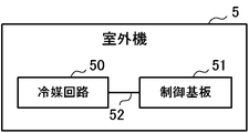
- the outdoor unit 5 includes a refrigerant circuit 50 and a control board 51, as shown in FIG.
- the refrigerant circuit 50 and the control board 51 are communicatively connected via a communication line 52.
- the refrigerant circuit 50 includes a compressor, a condenser, an expansion valve, an evaporator, and the like.
- the control board 51 is communicably connected to the indoor unit 4 via the communication line 7.
- the control board 51 is configured to include a CPU, a ROM, a RAM, a communication interface, a readable/writable nonvolatile semiconductor memory, etc. (none of which is shown).
- the control board 51 controls the operation of the refrigerant circuit 50, more specifically, the drive of the compressor, based on the control command received from the control board 46 of the indoor unit 4.
- the air conditioning remote controller 6 is a remote controller that is installed so as to be embedded in the wall of the room R or installed in a manner hung on the wall to accept operations related to air conditioning from a user who uses the room R.
- the user operates the air conditioning remote controller 6 to instruct to start or stop the operation, change the operation mode such as cooling, heating, dehumidification, and air blowing, and change the set temperature, set humidity, air blowing amount, air direction, and the like. It is also possible to set the timer.
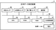
- the biometric data measuring device 3 is an example of the biometric data measuring device according to the present invention.
- the biometric data measuring device 3 is a human-body-mounted (for example, wristband type) device that measures biometric data of a user who uses the room R.
- the biological data includes body temperature, heart rate, sweat rate, and the like.
- the biological data measuring device 3 includes a body temperature sensor 30, a heart rate sensor 31, a sweat rate sensor 32, a communication unit 33, a CPU 34, a ROM 35, a RAM 36, and a secondary storage device 37. With. These components are connected to each other via a bus 38. Further, the biological data measuring device 3 includes a battery 39 such as a primary battery or a secondary battery that supplies electric power to each component.
- the body temperature sensor 30 measures the body temperature of the user wearing the biological data measuring device 3.
- the heart rate sensor 31 measures the heart rate of the user.
- the sweat rate sensor 32 measures the sweat rate of the user.
- the communication unit 33 is hardware that wirelessly communicates with the indoor unit 4.
- the CPU 34 controls the biological data measuring device 3 in a centralized manner.
- the ROM 35 stores a plurality of firmware and data used when these firmwares are executed.
- the RAM 36 is used as a work area of the CPU 34.
- the secondary storage device 37 is composed of a readable/writable nonvolatile semiconductor memory such as an EEPROM or a flash memory. Although not shown, the secondary storage device 37 stores a program for measuring biometric data, a program for communicating with the indoor unit 4, and data used when these programs are executed.
- the CPU 34 stores data (hereinafter, referred to as measurement data) in which the biometric data (that is, body temperature, heart rate, and sweat rate) measured by the body temperature sensor 30, the heart rate sensor 31, and the sweat rate sensor 32 are stored.
- the data is wirelessly transmitted to the indoor unit 4 via the communication unit 33 at regular time intervals (for example, one minute intervals).
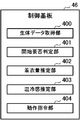
- control board 46 is functionally provided with a biometric data acquisition section 400, a start necessity determination section 401, a clothing amount estimation section 402, a thermal sensation estimation section 403, and an operation command section. And 404.
- These functional units are realized by the CPU 463 executing the above-described air conditioning control program stored in the secondary storage device 466.
- the biometric data acquisition unit 400 is an example of biometric data acquisition means according to the present invention.
- the biometric data acquisition unit 400 receives the above-described measurement data sent from the biometric data measuring device 3 periodically (for example, every one minute).
- the biometric data acquisition unit 400 extracts and acquires each biometric data (that is, body temperature, heart rate, and sweat rate) from the received measurement data.
- the biometric data acquisition unit 400 stores the acquired biometric data in a biometric data table (not shown) stored in the RAM 465 or the secondary storage device 466 in association with the time when the biometric data is acquired (that is, the time when the measurement data is received). ..
- the start necessity determination unit 401 determines whether or not it is necessary to start the air conditioning control (hereinafter referred to as comfort control) according to the user's thermal sensation so that the user feels comfortable. For example, the start necessity determination unit 401 determines that it is necessary to start comfort control when the elapsed time after the user enters the room R reaches a predetermined reference time. This is for avoiding execution of comfort control when the user's thermal sensation is unstable. The start necessity determination unit 401 may determine that the comfort control needs to be started when the heart rate of the user who has entered the room R has settled at a normal value.
- Whether or not the user has entered the room R can be determined from the communication status with the biological data measuring device 3 or the thermal image in the room R. That is, the start necessity determination unit 401 may determine that the user has entered the room R when the communication with the biological data measuring device 3 is started, or the person is reflected in the thermal image in the room R. If so, it may be determined that the user has entered the room R.
- the clothing amount estimation unit 402 estimates the clothing amount of the user who is in the room R.
- the clothing amount estimation unit 402 analyzes the thermal image acquired by the thermal image sensor 45 by a well-known method to estimate the surface temperature of the user's clothing portion (hereinafter referred to as clothing surface temperature).
- the clothing amount estimation unit 402 also acquires the latest body temperature of the user from the biometric data table. Then, the clothing amount estimation unit 402 estimates the clothing amount of the user according to the difference between the acquired body temperature of the user and the estimated clothing surface temperature.
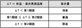
- the clothing amount estimation unit 402 when the difference ( ⁇ T) between the body temperature and the clothing surface temperature is smaller than a predetermined first threshold value, the clothing amount estimation unit 402 has a small amount of clothing for the user, That is, it is presumed that it is light clothing. If ⁇ T is equal to or larger than the first threshold and equal to or smaller than the second threshold set in advance, the clothing amount estimation unit 402 estimates that the clothing amount of the user is normal. When ⁇ T is larger than the second threshold, the clothing amount estimation unit 402 estimates that the clothing amount of the user is heavy clothing.
- the thermal sensation estimation unit 403 estimates the user's sense of the current thermal environment, that is, thermal sensation, based on the clothing amount of the user estimated by the clothing amount estimation unit 402. Specifically, when the user wears heavy clothing, the thermal sensation estimation unit 403 estimates that the user feels cold. Further, when the user wears light clothing, the thermal sensation estimation unit 403 estimates that the user feels hot. When the amount of clothing of the user is normal, the thermal sensation estimation unit 403 estimates that the user feels neither hot nor cold (that is, comfortable).
- the operation command unit 404 determines the content of the air conditioning control based on the user's thermal sensation estimated by the thermal sensation estimation unit 403, and the fan 40, the louver 41, and the outdoor unit 5 according to the determined content of the air conditioning control.
- the control command for each is generated and transmitted to each.
- the operation command unit 404 generates a control command for intensifying heating to each of the fan 40, the louver 41, and the outdoor unit 5 when the user feels cold during heating operation.
- a control command for increasing the set temperature (also referred to as a target temperature) by 1 to 3° C. or increasing the air flow rate is generated.
- the operation command unit 404 generates a control command for weakening the heating to each of the fan 40, the louver 41, and the outdoor unit 5 when the user feels hot during the heating operation.
- a control command for lowering the set temperature by 1 to 3° C. or reducing the air flow is generated.
- the operation command unit 404 generates a control command for strengthening the cooling to each of the fan 40, the louver 41, and the outdoor unit 5 when the user feels hot during the cooling operation.
- a control command for lowering the set temperature by 1 to 3° C. or increasing the blown air volume is generated.
- the operation command unit 404 generates a control command for weakening the cooling to each of the fan 40, the louver 41, and the outdoor unit 5 when the user feels cold during the cooling operation.
- a control command for increasing the set temperature by 1 to 3° C. or reducing the air flow is generated.
- the start necessity determination unit 401, the clothing amount estimation unit 402, the thermal sensation estimation unit 403, and the operation command unit 404 are examples of the air conditioning control unit according to the present invention.
- FIG. 8 is a flowchart showing the procedure of the air conditioning control process executed by the control board 46 of the indoor unit 4.
- the air conditioning control process is started when the user enters the room R.
- the clothing amount estimation unit 402 estimates the clothing amount of the user in the room R (step S102).
- the thermal sensation estimation unit 403 estimates the current thermal sensation of the user based on the clothing amount of the user estimated by the clothing amount estimation unit 402 (step S103).
- the operation command unit 404 determines the content of the air conditioning control based on the user's thermal sensation estimated by the thermal sensation estimation unit 403 (step S104).
- the operation command unit 404 generates a control command for each of the fan 40, the louver 41, and the outdoor unit 5 based on the determined content of the air conditioning control (step S105). Then, the operation command unit 404 transmits each generated control command to each of the fan 40, the louver 41, and the outdoor unit 5 (step S106).
- step S108 the CPU 463 of the control board 46 determines whether or not the user has exited the room R (step S108). ). Whether or not the user has left the room R can be determined from the communication status with the biological data measuring device 3 or the thermal image in the room R. That is, the CPU 463 may determine that the user has exited the room when communication with the biological data measuring device 3 is not possible, and when the person in the thermal image in the room R is not included in the room R, the user exits the room. You may judge that it has been completed.
- a predetermined waiting time for example, 10 minutes
- step S108 If the user has already left the room (step S108; YES), the CPU 463 ends the air conditioning control process. On the other hand, if the user has not left the room (step S108; NO), the process returns to step S102.
- the thermal sensation of the user is estimated and estimated based on the thermal image of the room R and the biometric data of the user who has entered the room R.
- the room R is air-conditioned according to the sense of heat and cold. This makes it possible to accurately realize comfortable air conditioning for the user in the room R.
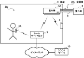
- FIG. 9 is a diagram showing an overall configuration of an air conditioning system 1A according to the second embodiment of the present invention.
- the air conditioning system 1A is a system for air conditioning the room R in the building, and as shown in FIG. 9, includes an air conditioner 2A, a biometric data measuring device 3A, a home gateway 9, and a cloud server 10.
- the air conditioner 2A is an example of the air conditioner according to the present invention.
- the air conditioner 2A includes an indoor unit 4A installed in the room R, an outdoor unit 5 installed outside the room R, and an air conditioning remote controller 6 installed in the room R.
- the indoor unit 4A and the outdoor unit 5 are connected via a communication line 7 and a refrigerant pipe 8 for circulating a refrigerant.
- the hardware configuration of the indoor unit 4A is the same as that of the indoor unit 4 of the first embodiment (see FIGS. 2 and 3). However, the third communication unit 462 of the control board 46 included in the indoor unit 4A communicates with the cloud server 10 connected to the Internet via the home gateway 9 having a function as a broadband router.
- the CPU 463 of the control board 46 included in the indoor unit 4A does not perform the air conditioning control according to the thermal sensation of the user in the room R as in the first embodiment, and instead, the heat acquired by the thermal image sensor 45 is used.
- Air conditioning information that stores the image, the current operating state (for example, operating or stopped, operating mode, set temperature, set humidity, etc.) and the current air state (room temperature, humidity, etc.) of the room R is fixed.
- the data is transmitted to the cloud server 10 at time intervals (for example, 1 minute intervals).
- the CPU 463 of the indoor unit 4A also performs air conditioning control according to control data from the cloud server 10 in addition to air conditioning control according to a user operation via the air conditioning remote controller 6.
- the hardware configuration of the biometric data measuring device 3A is the same as that of the biometric data measuring device 3 of the first embodiment (see FIG. 5). However, the communication unit 33 of the biometric data measuring device 3A communicates with the cloud server 10 via the home gateway 9.
- the CPU 34 of the biometric data measuring device 3A keeps constant the measurement data in which the biometric data (that is, the body temperature, the heart rate, and the sweat rate) measured by the body temperature sensor 30, the heart rate sensor 31, and the sweat rate sensor 32 are stored.
- the data is transmitted to the cloud server 10 at time intervals (for example, 1 minute intervals).
- the cloud server 10 is an example of the control device according to the present invention.
- the cloud server 10 is a server computer installed and operated by a manufacturer of the air conditioner 2A, a sales company, etc., and is connected to the Internet.
- the cloud server 10 includes a communication unit 11, a CPU 12, a ROM 13, a RAM 14, and a secondary storage device 15. These components are connected to each other via a bus 16.
- the communication unit 11 is hardware for connecting to the Internet and communicating with the indoor unit 4A and the biological data measuring device 3A via the home gateway 9.
- the CPU 12 centrally controls the cloud server 10. Details of the functions of the cloud server 10 realized by the CPU 12 will be described later.
- the ROM 13 stores a plurality of firmware and data used when these firmwares are executed.
- the RAM 14 is used as a work area of the CPU 12.
- the secondary storage device 15 is a large-capacity storage device configured to include a readable/writable non-volatile semiconductor memory such as an EEPROM or a flash memory, or an HDD (Hard Disk Drive).
- the secondary storage device 15 stores an air conditioning control program for executing the air conditioning control and data used when the air conditioning control program is executed.
- the cloud server 10 functionally has an air conditioning information acquisition unit 100, a biometric data acquisition unit 101, a start necessity determination unit 102, a clothing amount estimation unit 103, and a thermal sensation estimation.
- the unit 104 and the operation command unit 105 are provided. These functional units are realized by the CPU 12 executing the above-described air conditioning control program stored in the secondary storage device 15.
- the air conditioning information acquisition unit 100 is an example of an air conditioning information acquisition unit according to the present invention.
- the air-conditioning information acquisition unit 100 receives and acquires the above-mentioned air-conditioning information sent from the indoor unit 4A periodically (for example, every minute).
- the air conditioning information acquisition unit 100 stores the received air conditioning information in an air conditioning information table (not shown) stored in the secondary storage device 15 in association with the time of reception.
- the biometric data acquisition unit 101 is an example of biometric data acquisition means according to the present invention.
- the biometric data acquisition unit 101 receives the above-described measurement data sent from the biometric data measuring device 3A periodically (for example, every one minute).
- the biometric data acquisition unit 101 extracts and acquires each biometric data (that is, body temperature, heart rate, and sweat rate) from the received measurement data.
- the biometric data acquisition unit 101 stores the acquired biometric data in a biometric data table (not shown) stored in the secondary storage device 15 in association with the time when the biometric data was acquired (that is, the time when the measurement data was received).
- the start necessity determination unit 102 determines whether or not it is necessary to start comfort control by the same method as the start necessity determination unit 401 of the first embodiment.
- the clothing amount estimation unit 103 estimates the amount of clothing of the user who is in the room R in the same manner as the clothing amount estimation unit 402 of the first embodiment.
- the thermal sensation estimation unit 104 estimates the current thermal sensation of the user by the same method as the thermal sensation estimation unit 403 of the first embodiment.
- the operation command unit 105 determines the content of the air conditioning control by the same method as the operation command unit 404 of the first embodiment.
- the operation command unit 105 generates control data based on the determined content of the air conditioning control, and transmits the control data to the indoor unit 4A of the air conditioner 2A.
- the indoor unit 4A that has received the control data executes the air conditioning control indicated by the control data.
- the start necessity determination unit 102, the clothing amount estimation unit 103, the thermal sensation estimation unit 104, and the operation command unit 105 are an example of an air conditioning control unit according to the present invention.
- the cloud server 10 determines the thermal sensation of the user based on the thermal image of the room R and the biometric data of the user in the room R.
- the air conditioning of the room R is performed by controlling the air conditioner 2A according to the estimated thermal sensation. This makes it possible to accurately realize comfortable air conditioning for the user.
- the biometric data measuring device 3A may be replaced with the biometric data measuring device 3.
- the biological data measuring device 3 transmits the measurement data to the indoor unit 4A
- the indoor unit 4A transmits the measurement data received from the biological data measuring device 3 to the cloud server 10.
- the amount of clothing in each of the above-mentioned embodiments, three levels of indicators of light wear, normal wear, and heavy wear are shown, but the degree of light wear and heavy wear may be indicated in multiple levels. Alternatively, the amount of clothing may be indicated by a numerical value.
- the threshold value (for example, the above-mentioned first threshold value and second threshold value) that is compared with the difference ( ⁇ T) between the body temperature and the clothing surface temperature may be changed according to the season.
- the estimated user's thermal sensation is not limited to “hot”, “comfortable”, or “cold”, and may be “slightly hot”, “very hot”, “slightly cold”, “very cold”, etc. , May be estimated in more detail.
- the indoor unit 4 or the cloud server 10 may estimate the activity amount of the user who has entered the room R and may determine the content of the air conditioning control in consideration of the estimated activity amount.
- the amount of user activity is estimated by the heart rate and/or the amount of sweat.
- the indoor unit 4 or the cloud server 10 may estimate the amount of activity by calculating the amount of movement of the user from the thermal image.
- the reference time used when determining whether or not the comfort control needs to be started, the degree of air conditioning strength according to the user's thermal sensation, etc. are appropriately updated by learning based on the operation of the air conditioning remote controller 6 by the user. It may be done.
- biometric data measuring devices 3 and 3A may be configured to further include other sensors for measuring biometric data, or may be configured to include only the body temperature sensor 30.
- the biometric data measuring devices 3 and 3A may be configured by one or a plurality of sensors that measure biometric data and a data collecting device that is connected to each sensor in a wired or wireless manner. In this case, each sensor is attached to an appropriate place on the user's body.
- control board 46 of the indoor units 4 and 4A may be realized by the control board 51 of the outdoor unit 5.
- a control device having the same function as the cloud server 10 may be installed in the building having the room R.
- the air conditioning control program stored in the secondary storage device 15 is executed by the CPU 12 of the CPU cloud server 10 to realize the functional unit of the cloud server 10 (see FIG. 11 ). Was done.
- the dedicated hardware is, for example, a single circuit, a composite circuit, a programmed processor, an ASIC (Application Specific Integrated Circuit), an FPGA (Field-Programmable Gate Array), or a combination thereof.
- ASIC Application Specific Integrated Circuit
- FPGA Field-Programmable Gate Array
- the above-mentioned air conditioning control program is used for CD-ROM (Compact Disc Read Only Memory), DVD (Digital Versatile Disc), magneto-optical disc (Magneto-Optical Disc), USB (Universal Serial Bus) memory, memory card, HDD, etc. It is also possible to store it in a computer-readable recording medium and distribute it. Then, by installing the air conditioning control program on a specific or general-purpose computer, it is possible to cause the computer to function as the cloud server 10 in the second embodiment.
- CD-ROM Compact Disc Read Only Memory
- DVD Digital Versatile Disc
- magneto-optical disc Magneto-optical disc
- USB Universal Serial Bus
- the air conditioning control program may be stored in a storage device included in a server (not shown) on the Internet, and the air conditioning control program may be downloaded from the server to the cloud server 10.
- the present invention can be suitably applied to a system for air conditioning in a building.
Abstract
空調機の室内機(4)は、屋内の熱画像を取得する熱画像センサ(45)と、空調制御を行う制御基板(46)とを備える。制御基板(46)は、ユーザに装着される生体データ測定装置から測定された生体データを取得する。生体データ測定装置により測定される生体データには、少なくともユーザの体温が含まれている。制御基板(46)は、熱画像センサ(45)により取得された熱画像と、生体データ測定装置から取得した生体データとに基づいて、空調制御を行う。
Description
本発明は、空調機、制御装置、空調システム、空調制御方法及びプログラムに関する。
一般に、空調機は、室内の温度、湿度、気流等の環境的要因を調整して、在室者の快適性を維持する。しかし、室内の温熱環境に対する感覚(即ち、温冷感)は、個々人で様々であるため、環境的要因のみに依拠した空調では、適切に在室者の快適性を維持するのは困難である。
これに対し、空調機が備える赤外線サーモグラフィによって得られた室内の熱画像から在室者の体温を定めることで温冷感を推定し、推定した温冷感に基づいて空調を行う技術が知られている(例えば、特許文献1)。
しかしながら、熱画像でユーザの体温を正確に定めることは困難であり、その結果、当該ユーザの温冷感の推定精度を下げることになり、当該ユーザのための快適な空調に支障を来すという課題がある。
本発明は、上記課題を解決するためになされたものであり、ユーザにとって快適な空調を精度よく実現するための空調機等を提供することを目的とする。
上記目的を達成するため、本発明に係る空調機は、
屋内の空気調整を行う空調機であって、
前記屋内の熱画像を取得する熱画像センサと、
ユーザに装着され、前記ユーザの体温を少なくとも含む生体データを測定する生体データ測定装置から前記生体データを取得する生体データ取得手段と、
前記取得された熱画像と、前記取得された生体データとに基づいて、空調制御を行う空調制御手段と、を備える。
屋内の空気調整を行う空調機であって、
前記屋内の熱画像を取得する熱画像センサと、
ユーザに装着され、前記ユーザの体温を少なくとも含む生体データを測定する生体データ測定装置から前記生体データを取得する生体データ取得手段と、
前記取得された熱画像と、前記取得された生体データとに基づいて、空調制御を行う空調制御手段と、を備える。
本発明によれば、ユーザにとって快適な空調を精度よく実現することが可能となる。
以下、本発明の実施の形態について図面を参照して詳細に説明する。
実施の形態1.
図1は、本発明の実施の形態1に係る空調システム1の全体構成を示す図である。空調システム1は、建物内における部屋Rの空調を行うシステムであり、図1に示すように、空調機2と、生体データ測定装置3とを備える。
図1は、本発明の実施の形態1に係る空調システム1の全体構成を示す図である。空調システム1は、建物内における部屋Rの空調を行うシステムであり、図1に示すように、空調機2と、生体データ測定装置3とを備える。
空調機2は、本発明に係る空調機の一例である。空調機2は、部屋Rに設置される室内機4と、部屋Rの外に設置される室外機5と、部屋Rに設置される空調リモコン6とを備える。室内機4と室外機5は、通信線7と、冷媒を循環させるための冷媒配管8とを介して接続される。
室内機4は、図2に示すように、ファン40と、ルーバ41と、熱交換器42と、温度センサ43と、湿度センサ44と、熱画像センサ45と、制御基板46とを備える。
ファン40は、例えば、シロッコファンであり、部屋Rの空気を室内機4の図示しない吸込口から取り込むと共に、室内機4の図示しない吹出口から、熱交換器42によって熱交換された空気を送り出す。ファン40は、制御基板46と通信線CL1を介して通信可能に接続される。ファン40の回転数、即ち、ファン40による送風量は、制御基板46からの制御指令に従って調整される。
ルーバ41は、ファン40によって部屋Rに送り出される空気の向きを調整する。ルーバ41は、制御基板46と通信線CL2を介して通信可能に接続される。ルーバ41の角度、即ち、風向きは、制御基板46からの制御指令に従って調整される。
熱交換器42は、ファン40により取り込まれた空気と室外機5からの冷媒との熱交換を行う。熱交換器42は、冷房運転時においては、蒸発器として機能し、暖房運転時においては、凝縮器として機能する。
温度センサ43は、ファン40により取り込まれた空気の温度を測定する。温度センサ43は、通信線CL3を介して制御基板46と通信可能に接続される。温度センサ43は、制御基板46からの要求に応答して、測定した温度を示すデータ(以下、温度データという。)を制御基板46に送信する。
湿度センサ44は、ファン40により取り込まれた空気の湿度を測定する。湿度センサ44は、通信線CL4を介して制御基板46と通信可能に接続される。湿度センサ44は、制御基板46からの要求に応答して、測定した湿度を示すデータ(以下、湿度データという。)を制御基板46に送信する。
熱画像センサ45は、本発明に係る熱画像センサの一例である。熱画像センサ45は、赤外線サーモグラフィであり、部屋R内の熱画像を取得する。熱画像センサ45は、通信線CL5を介して制御基板46と通信可能に接続される。熱画像センサ45は、制御基板46からの要求に応答して、取得した熱画像を示すデータ(以下、熱画像データという。)を制御基板46に送信する。
制御基板46は、図3に示すように、第1通信部460と、第2通信部461と、第3通信部462と、CPU463と、ROM464と、RAM465と、二次記憶装置466とを備える。これらの構成部は、バス467を介して相互に接続される。
第1通信部460は、通信線7を介して室外機5と通信を行うハードウェアである。第2通信部461は、空調リモコン6と赤外線通信等の無線通信を行うハードウェアである。第3通信部462は、生体データ測定装置3とWi-Fi(登録商標)、BLE(Bluetooth Low Energy;Bluetoothは登録商標)等の通信規格に則った無線通信を行うハードウェアである。
CPU(Central Processing Unit)463は、空調機2を統括的に制御する。即ち、一般的な室内機と同様、空調リモコン6を介してユーザにより操作された内容に従った空調を行うようファン40、ルーバ41を制御し、また、室外機5の動作を制御する。さらに、CPU463は、部屋Rに居るユーザの温冷感に従った空調制御も行う。CPU463によって実現される制御基板46の特有の機能の詳細については後述する。
ROM(Read Only Memory)464は、複数のファームウェア及びこれらのファームウェアの実行時に使用されるデータを記憶する。RAM(Random Access Memory)465は、CPU463の作業領域として使用される。
二次記憶装置466は、EEPROM(Electrically Erasable Programmable Read-Only Memory)、フラッシュメモリ等の読み書き可能な不揮発性の半導体メモリで構成される。二次記憶装置466は、空調制御を実行するための空調制御プログラムと、空調制御プログラムの実行時に使用されるデータとを記憶する。
室外機5は、図4に示すように、冷媒回路50と、制御基板51とを備える。冷媒回路50と制御基板51は、通信線52を介して通信可能に接続される。冷媒回路50は、何れも図示しないが、圧縮機、凝縮器、膨張弁、蒸発器などを備える。制御基板51は、室内機4と通信線7を介して通信可能に接続される。制御基板51は、CPU、ROM、RAM、通信インタフェース、読み書き可能な不揮発性の半導体メモリなど(何れも図示せず)を含んで構成される。制御基板51は、室内機4の制御基板46から受信した制御指令に基づいて、冷媒回路50の運転、より詳細には、圧縮機の駆動を制御する。
空調リモコン6は、部屋Rの壁に埋設して設置されたり、あるいは壁に掛けられた態様で設置され、部屋Rを利用するユーザから、空調に関する操作を受け付けるためのリモートコントローラである。例えば、ユーザは、空調リモコン6を操作することで、運転の開始又は停止、冷房、暖房、除湿、送風などの運転モードの変更、設定温度、設定湿度、送風量、風向き等の変更を指示することができ、また、タイマ設定を行うことができる。
生体データ測定装置3は、本発明に係る生体データ測定装置の一例である。生体データ測定装置3は、部屋Rを利用するユーザの生体データを測定する人体装着型(例えば、リストバンド型)の装置である。生体データには、体温、心拍数、発汗量等が含まれる。図5に示すように、生体データ測定装置3は、体温センサ30と、心拍数センサ31と、発汗量センサ32と、通信部33と、CPU34と、ROM35と、RAM36と、二次記憶装置37とを備える。これらの構成部は、バス38を介して相互に接続される。また、生体データ測定装置3は、各構成部に電力を供給する一次電池、二次電池等の電池39を備える。
体温センサ30は、当該生体データ測定装置3を装着したユーザの体温を測定する。心拍数センサ31は、当該ユーザの心拍数を測定する。発汗量センサ32は、当該ユーザの発汗量を測定する。通信部33は、室内機4と無線通信を行うハードウェアである。
CPU34は、当該生体データ測定装置3を統括的に制御する。ROM35は、複数のファームウェア及びこれらのファームウェアの実行時に使用されるデータを記憶する。RAM36は、CPU34の作業領域として使用される。
二次記憶装置37は、EEPROM、フラッシュメモリ等の読み書き可能な不揮発性の半導体メモリで構成される。二次記憶装置37は、図示しないが、生体データの測定に関するプログラム及び室内機4と通信するためのプログラムと、これらのプログラムの実行時に使用されるデータとを記憶する。
CPU34は、体温センサ30、心拍数センサ31及び発汗量センサ32の各々により測定された各生体データ(即ち、体温、心拍数及び発汗量)が格納されたデータ(以下、測定データという。)を一定時間間隔(例えば、1分間隔)で通信部33を介して室内機4に無線送信する。
続いて、室内機4が備える制御基板46の特有の機能について詳細に説明する。図6に示すように、制御基板46は、機能的には、生体データ取得部400と、開始要否判定部401と、着衣量推定部402と、温冷感推定部403と、動作指令部404とを備える。これらの機能部は、CPU463が二次記憶装置466に記憶されている上記の空調制御プログラムを実行することで実現される。
生体データ取得部400は、本発明に係る生体データ取得手段の一例である。生体データ取得部400は、生体データ測定装置3から定期的(例えば、1分毎)に送られてくる前述した測定データを受信する。生体データ取得部400は、受信した測定データから、各生体データ(即ち、体温、心拍数及び発汗量)を抽出して取得する。生体データ取得部400は、取得した各生体データを取得した時刻(即ち、測定データを受信した時刻)と対応付けて、RAM465又は二次記憶装置466に記憶される図示しない生体データテーブルに格納する。
開始要否判定部401は、ユーザが快適感を得るように当該ユーザの温冷感に従った空調制御(以下、快適制御という。)を開始する必要があるか否かを判定する。例えば、開始要否判定部401は、ユーザが部屋Rに入室してからの経過時間が予め定めた基準時間に達した場合、快適制御を開始する必要があると判定する。これは、ユーザの温冷感が不安定な状態での快適制御の実行を回避するためである。なお、開始要否判定部401は、部屋Rに入室したユーザの心拍数が平常値に落ち着いた場合、快適制御を開始する必要があると判定してもよい。
ユーザが部屋Rに入室したか否かについては、生体データ測定装置3との通信状況又は部屋R内の熱画像から判定することが可能である。即ち、開始要否判定部401は、生体データ測定装置3との通信が開始されると、ユーザが部屋Rに入室したと判定してもよいし、部屋R内の熱画像に人が映り込んでいる場合、ユーザが部屋Rに入室したと判定してもよい。
着衣量推定部402は、部屋Rに在室中のユーザの着衣量を推定する。詳細には、着衣量推定部402は、熱画像センサ45により取得された熱画像を周知の手法により解析して、ユーザの着衣部分における表面温度(以下、着衣表面温度という。)を推定する。また、着衣量推定部402は、上記の生体データテーブルからユーザの最新の体温を取得する。そして、着衣量推定部402は、取得したユーザの体温と推定した着衣表面温度との差に応じて、当該ユーザの着衣量を推定する。
具体的には、図7に示すように、体温と着衣表面温度との差(ΔT)が、予め定めた第1閾値より小さい場合、着衣量推定部402は、当該ユーザの着衣量が少ない、即ち、薄着であると推定する。また、ΔTが、第1閾値以上であり、予め定めた第2閾値以下の場合、着衣量推定部402は、当該ユーザの着衣量が普通であると推定する。また、ΔTが、第2閾値より大きい場合、着衣量推定部402は、当該ユーザの着衣量が厚着であると推定する。
温冷感推定部403は、着衣量推定部402により推定されたユーザの着衣量に基づいて、ユーザの現在の温熱環境に対する感覚、即ち、温冷感を推定する。詳細には、ユーザの着衣量が厚着の場合、温冷感推定部403は、ユーザは寒いと感じていると推定する。また、ユーザの着衣量が薄着の場合、温冷感推定部403は、ユーザは暑いと感じていると推定する。ユーザの着衣量が普通の場合、温冷感推定部403は、ユーザは暑くもなく寒くもない(即ち、快適)と感じていると推定する。
動作指令部404は、温冷感推定部403により推定されたユーザの温冷感に基づいて、空調制御の内容を決定し、決定した空調制御の内容に従って、ファン40、ルーバ41及び室外機5を動作させるよう各々に対する制御指令を生成し、各々に送信する。
詳細には、動作指令部404は、暖房運転時において、ユーザが寒いと感じている場合、ファン40、ルーバ41及び室外機5の各々に対して、暖房を強めるための制御指令を生成する。この場合、例えば、設定温度(目標温度ともいう。)を1~3℃上げたり、あるいは、送風量を増加させるための制御指令を生成する。
また、動作指令部404は、暖房運転時において、ユーザが暑いと感じている場合、ファン40、ルーバ41及び室外機5の各々に対して、暖房を弱めるための制御指令を生成する。この場合、例えば、設定温度を1~3℃下げたり、送風量を低下させるための制御指令を生成する。
また、動作指令部404は、冷房運転時において、ユーザが暑いと感じている場合、ファン40、ルーバ41及び室外機5の各々に対して、冷房を強めるための制御指令を生成する。この場合、例えば、設定温度を1~3℃下げたり、送風量を増加させるための制御指令を生成する。
また、動作指令部404は、冷房運転時において、ユーザが寒いと感じている場合、ファン40、ルーバ41及び室外機5の各々に対して、冷房を弱めるための制御指令を生成する。この場合、例えば、設定温度を1~3℃上げたり、送風量を低下させるための制御指令を生成する。
開始要否判定部401、着衣量推定部402、温冷感推定部403及び動作指令部404は、本発明に係る空調制御手段の一例である。
図8は、室内機4の制御基板46によって実行される空調制御処理の手順を示すフローチャートである。空調制御処理は、部屋Rにユーザが入室すると開始される。
開始要否判定部401が、快適制御を開始する必要があると判定すると(ステップS101:YES)、着衣量推定部402は、部屋Rに居るユーザの着衣量を推定する(ステップS102)。温冷感推定部403は、着衣量推定部402により推定されたユーザの着衣量に基づいて、ユーザの現在の温冷感を推定する(ステップS103)。
動作指令部404は、温冷感推定部403により推定されたユーザの温冷感に基づいて、空調制御の内容を決定する(ステップS104)。動作指令部404は、決定した空調制御の内容に基づいて、ファン40、ルーバ41及び室外機5の各々に対する制御指令を生成する(ステップS105)。そして、動作指令部404は、生成した各制御指令をファン40、ルーバ41及び室外機5の各々に送信する(ステップS106)。
ステップS106の処理後、予め定めた待機時間(例えば、10分)が経過すると(ステップS107;YES)、制御基板46のCPU463は、ユーザが部屋Rから退室済みか否かを判定する(ステップS108)。ユーザが部屋Rから退室済みか否かについては、生体データ測定装置3との通信状況又は部屋R内の熱画像から判定することが可能である。即ち、CPU463は、生体データ測定装置3との通信ができない状態であると、ユーザが退室済みと判定してもよいし、部屋R内の熱画像に人が映り込んでいない場合、ユーザが退室済みと判定してもよい。
ユーザが退室済みの場合(ステップS108;YES)、CPU463は、空調制御処理を終了する。一方、ユーザが退室済みでない場合(ステップS108;NO)、ステップS102に戻る。
以上説明したように、実施の形態1に係る空調システム1では、部屋R内の熱画像と、部屋Rに入室したユーザの生体データとに基づいて、当該ユーザの温冷感を推定し、推定した温冷感に従って、部屋Rの空調を行う。これにより、部屋Rに居るユーザにとって快適な空調を精度よく実現することが可能となる。
実施の形態2.
続いて、本発明の実施の形態2について説明する。なお、以下の説明において、実施の形態1と共通する構成要素等については、同一の符号を付し、その説明を省略する。
続いて、本発明の実施の形態2について説明する。なお、以下の説明において、実施の形態1と共通する構成要素等については、同一の符号を付し、その説明を省略する。
図9は、本発明の実施の形態2に係る空調システム1Aの全体構成を示す図である。空調システム1Aは、建物内における部屋Rの空調を行うシステムであり、図9に示すように、空調機2Aと、生体データ測定装置3Aと、ホームゲートウェイ9と、クラウドサーバ10とを備える。
空調機2Aは、本発明に係る空調機の一例である。空調機2Aは、部屋Rに設置される室内機4Aと、部屋Rの外に設置される室外機5と、部屋Rに設置される空調リモコン6とを備える。室内機4Aと室外機5は、通信線7と、冷媒を循環させるための冷媒配管8とを介して接続される。
室内機4Aのハードウェア構成は、実施の形態1の室内機4と同様(図2、図3参照)である。ただし、室内機4Aが備える制御基板46の第3通信部462は、ブロードバンドルータとしての機能を有するホームゲートウェイ9を介して、インターネットに接続されるクラウドサーバ10と通信を行う。
室内機4Aが備える制御基板46のCPU463は、実施の形態1のように、部屋Rに居るユーザの温冷感に従った空調制御を行わず、代わりに、熱画像センサ45により取得された熱画像と、現在の運転状態(例えば、運転中又は停止中、運転モード、設定温度、設定湿度等)と、現在の部屋Rの空気状態(室温、湿度等)とが格納された空調情報を一定時間間隔(例えば、1分間隔)でクラウドサーバ10に送信する。また、室内機4AのCPU463は、空調リモコン6を介したユーザ操作に従った空調制御に加え、クラウドサーバ10からの制御データに従った空調制御も行う。
生体データ測定装置3Aのハードウェア構成は、実施の形態1の生体データ測定装置3と同様(図5参照)である。ただし、生体データ測定装置3Aの通信部33は、ホームゲートウェイ9を介してクラウドサーバ10と通信を行う。
生体データ測定装置3AのCPU34は、体温センサ30、心拍数センサ31及び発汗量センサ32の各々により測定された各生体データ(即ち、体温、心拍数及び発汗量)が格納された測定データを一定時間間隔(例えば、1分間隔)でクラウドサーバ10に送信する。
クラウドサーバ10は、本発明に係る制御装置の一例である。クラウドサーバ10は、空調機2Aのメーカ、販売会社等によって設置され、運用されるサーバコンピュータであり、インターネットに接続される。クラウドサーバ10は、図10に示すように、通信部11と、CPU12と、ROM13と、RAM14と、二次記憶装置15とを備える。これらの構成部は、バス16を介して相互に接続される。
通信部11は、インターネットに接続し、ホームゲートウェイ9を介して室内機4A、生体データ測定装置3Aと通信するためのハードウェアである。CPU12は、当該クラウドサーバ10を統括的に制御する。CPU12によって実現されるクラウドサーバ10の機能の詳細については後述する。
ROM13は、複数のファームウェア及びこれらのファームウェアの実行時に使用されるデータを記憶する。RAM14は、CPU12の作業領域として使用される。
二次記憶装置15は、EEPROM、フラッシュメモリ等の読み書き可能な不揮発性の半導体メモリ又はHDD(Hard Disk Drive)を含んで構成される大容量の記憶装置である。二次記憶装置15は、空調制御を実行するための空調制御プログラムと、空調制御プログラムの実行時に使用されるデータとを記憶する。
クラウドサーバ10は、機能的には、図11に示すように、空調情報取得部100と、生体データ取得部101と、開始要否判定部102と、着衣量推定部103と、温冷感推定部104と、動作指令部105とを備える。これらの機能部は、CPU12が二次記憶装置15に記憶されている上記の空調制御プログラムを実行することで実現される。
空調情報取得部100は、本発明に係る空調情報取得手段の一例である。空調情報取得部100は、室内機4Aから定期的(例えば、1分毎)に送られてくる前述した空調情報を受信して取得する。空調情報取得部100は、受信した空調情報を受信した時刻と対応付けて、二次記憶装置15に記憶される図示しない空調情報テーブルに格納する。
生体データ取得部101は、本発明に係る生体データ取得手段の一例である。生体データ取得部101は、生体データ測定装置3Aから定期的(例えば、1分毎)に送られてくる前述した測定データを受信する。生体データ取得部101は、受信した測定データから、各生体データ(即ち、体温、心拍数及び発汗量)を抽出して取得する。生体データ取得部101は、取得した各生体データを取得した時刻(即ち、測定データを受信した時刻)と対応付けて、二次記憶装置15に記憶される図示しない生体データテーブルに格納する。
開始要否判定部102は、実施の形態1の開始要否判定部401と同様の手法で、快適制御を開始する必要があるか否かを判定する。
着衣量推定部103は、実施の形態1の着衣量推定部402と同様の手法で、部屋Rに在室中のユーザの着衣量を推定する。
温冷感推定部104は、実施の形態1の温冷感推定部403と同様の手法で、ユーザの現在の温冷感を推定する。
動作指令部105は、実施の形態1の動作指令部404と同様の手法で、空調制御の内容を決定する。動作指令部105は、決定した空調制御の内容に基づいて制御データを生成し、空調機2Aの室内機4Aに送信する。かかる制御データを受信した室内機4Aは、当該制御データで示される空調制御を実行する。これにより、実施の形態1と同様に、部屋Rに居るユーザの温冷感に従った空調を実現できる。
開始要否判定部102、着衣量推定部103、温冷感推定部104及び動作指令部105は、本発明に係る空調制御手段の一例である。
以上説明したように、実施の形態2に係る空調システム1Aでは、クラウドサーバ10は、部屋R内の熱画像と、部屋Rに居るユーザの生体データとに基づいて、当該ユーザの温冷感を推定し、推定した温冷感に従って、空調機2Aを制御して部屋Rの空調を行う。これにより、ユーザにとって快適な空調を精度よく実現することが可能となる。
なお、空調システム1Aの変形例として、生体データ測定装置3Aを生体データ測定装置3に替えてもよい。この場合、生体データ測定装置3が、室内機4Aに測定データを送信し、室内機4Aが、生体データ測定装置3から受信した測定データをクラウドサーバ10に送信する。
本発明は、上記の各実施の形態に限定されず、本発明の要旨を逸脱しない範囲での種々の変更は勿論可能である。
例えば、上記の各実施の形態では、着衣量として、薄着、普通、厚着の3段階の指標を例示したが、さらに、薄着、厚着の程度を各々複数段階で示してもよい。あるいは、着衣量を数値で示してもよい。
また、着衣量を推定する際に、体温と着衣表面温度との差(ΔT)と比較する閾値(例えば、上述した第1閾値、第2閾値)は、季節に応じて変更してもよい。
また、推定するユーザの温冷感は、「暑い」、「快適」又は「寒い」の何れかに限定されず、「やや暑い」、「大変暑い」、「やや寒い」、「大変寒い」等、さらに詳細に推定してもよい。
また、室内機4又はクラウドサーバ10は、部屋Rに入室したユーザの活動量を推定し、推定した活動量も加味して空調制御の内容を決定してもよい。ユーザの活動量は、心拍数及び/又は発汗量によって推定される。あるいは、室内機4又はクラウドサーバ10は、熱画像からユーザの移動量を算出することで、活動量を推定してもよい。
また、快適制御の開始の要否を判定する際に使用される基準時間、ユーザの温冷感に応じた空調の強弱の度合等は、ユーザによる空調リモコン6の操作に基づいた学習により適宜更新されるようにしてもよい。
また、生体データ測定装置3,3Aは、さらに他の生体データを測定するセンサを備える構成であってもよいし、体温センサ30のみを備える構成であってもよい。
また、生体データ測定装置3,3Aを、生体データを測定する1又は複数のセンサと、各センサと有線又は無線にて通信可能に接続されるデータ収集装置とにより構成してもよい。この場合、各センサは、それぞれユーザの身体の適切な場所に装着される。
また、室内機4,4Aの制御基板46の機能が、室外機5の制御基板51により実現される構成であってもよい。
また、部屋Rを有する建物内に、クラウドサーバ10と同等の機能を有する制御装置を設置してもよい。
また、上記の実施の形態2では、CPUクラウドサーバ10のCPU12によって二次記憶装置15に記憶されている空調制御プログラムが実行されることで、クラウドサーバ10の機能部(図11参照)が実現された。
しかし、クラウドサーバ10の機能部の全部又は一部が、専用のハードウェアで実現されるようにしてもよい。専用のハードウェアとは、例えば、単一回路、複合回路、プログラム化されたプロセッサ、ASIC(Application Specific Integrated Circuit)、FPGA(Field-Programmable Gate Array)、又は、これらの組み合わせである。
また、上記の空調制御プログラムは、CD-ROM(Compact Disc Read Only Memory)、DVD(Digital Versatile Disc)、光磁気ディスク(Magneto-Optical Disc)、USB(Universal Serial Bus)メモリ、メモリカード、HDD等のコンピュータ読み取り可能な記録媒体に格納して配布することも可能である。そして、空調制御プログラムを特定の又は汎用のコンピュータにインストールすることによって、当該コンピュータを上記の実施の形態2におけるクラウドサーバ10として機能させることも可能である。
また、空調制御プログラムをインターネット上の図示しないサーバが有する記憶装置に格納しておき、当該サーバからクラウドサーバ10に空調制御プログラムがダウンロードされるようにしてもよい。
本発明は、広義の精神と範囲を逸脱することなく、様々な実施の形態及び変形が可能である。また、上述した実施の形態は、本発明を説明するためのものであり、本発明の範囲を限定するものではない。つまり、本発明の範囲は、実施の形態ではなく、請求の範囲によって示される。そして、請求の範囲内及びそれと同等の発明の意義の範囲内で施される様々な変形が、本発明の範囲内とみなされる。
本発明は、建物内の空調を行うシステムに好適に採用され得る。
1,1A 空調システム、2,2A 空調機、3,3A 生体データ測定装置、4,4A 室内機、5 室外機、6 空調リモコン、7,52 通信線、8 冷媒配管、9 ホームゲートウェイ、10 クラウドサーバ、11,33 通信部、12,34,463 CPU、13,35,464 ROM、14,36,465 RAM、15,37,466 二次記憶装置、16,38,467 バス、30 体温センサ、31 心拍数センサ、32 発汗量センサ、39 電池、40 ファン、41 ルーバ、42 熱交換器、43 温度センサ、44 湿度センサ、45 熱画像センサ、46 制御基板、50 冷媒回路、51 制御基板、100 空調情報取得部、101 生体データ取得部、102 開始要否判定部、103 着衣量推定部、104 温冷感推定部、105 動作指令部、400 生体データ取得部、401 開始要否判定部、402 着衣量推定部、403 温冷感推定部、404 動作指令部、460 第1通信部、461 第2通信部、462 第3通信部
Claims (12)
- 屋内の空気調整を行う空調機であって、
前記屋内の熱画像を取得する熱画像センサと、
ユーザに装着され、前記ユーザの体温を少なくとも含む生体データを測定する生体データ測定装置から前記生体データを取得する生体データ取得手段と、
前記取得された熱画像と、前記取得された生体データとに基づいて、空調制御を行う空調制御手段と、を備える、空調機。 - 前記空調制御手段は、前記熱画像と、前記生体データとに基づいて、前記ユーザの着衣量を推定し、推定した着衣量に基づいて、前記ユーザの温冷感を推定し、推定した温冷感に基づいて、前記空調制御を行う、請求項1に記載の空調機。
- 前記空調制御手段は、前記熱画像から前記ユーザの着衣部分における表面温度を推定し、前記生体データに含まれる前記ユーザの体温と前記推定した表面温度との差に基づいて、前記ユーザの着衣量を推定する、請求項2に記載の空調機。
- 前記空調制御手段は、前記ユーザが前記屋内に入ってからの経過時間も加味して、前記空調制御を行う、請求項1から3の何れか1項に記載の空調機。
- 屋内の熱画像を取得する熱画像センサを備える空調機から前記熱画像を含む空調情報を取得する空調情報取得手段と、
ユーザに装着され、前記ユーザの体温を少なくとも含む生体データを測定する生体データ測定装置から前記生体データを取得する生体データ取得手段と、
前記取得された空調情報に含まれる熱画像と、前記取得された生体データとに基づいて、前記空調機を制御する空調制御手段と、を備える、制御装置。 - 前記空調制御手段は、前記熱画像と、前記生体データとに基づいて、前記ユーザの着衣量を推定し、推定した着衣量に基づいて、前記ユーザの温冷感を推定し、推定した温冷感に基づいて、前記空調機を制御する、請求項5に記載の制御装置。
- 前記空調制御手段は、前記熱画像から前記ユーザの着衣部分における表面温度を推定し、前記生体データに含まれる前記ユーザの体温と前記推定した表面温度との差に基づいて、前記ユーザの着衣量を推定する、請求項6に記載の制御装置。
- 前記空調制御手段は、前記ユーザが前記屋内に入ってからの経過時間も加味して、前記空調機を制御する、請求項5から7の何れか1項に記載の制御装置。
- ユーザに装着され、前記ユーザの生体データを測定する生体データ測定装置と、
請求項1から4の何れか1項に記載の空調機と、を備える、空調システム。 - 屋内の熱画像を取得する熱画像センサを備える空調機と、
ユーザに装着され、前記ユーザの生体データを測定する生体データ測定装置と、
請求項5から8の何れか1項に記載の制御装置と、を備える、空調システム。 - 屋内の熱画像を取得し、
ユーザに装着され、前記ユーザの生体データを測定する生体データ測定装置から前記生体データを取得し、
前記取得した熱画像と、前記取得した生体データとに基づいて、前記屋内の空調の制御を行う、空調制御方法。 - コンピュータを、
屋内の熱画像を取得する熱画像センサを備える空調機から前記熱画像を含む空調情報を通信により取得する空調情報取得手段、
ユーザに装着され、前記ユーザの生体データを測定する生体データ測定装置から前記生体データを通信により取得する生体データ取得手段、
前記取得された空調情報に含まれる熱画像と、前記取得された生体データとに基づいて、前記空調機を制御する空調制御手段、として機能させる、プログラム。
Priority Applications (2)
| Application Number | Priority Date | Filing Date | Title |
|---|---|---|---|
| PCT/JP2018/045275 WO2020121370A1 (ja) | 2018-12-10 | 2018-12-10 | 空調機、制御装置、空調システム、空調制御方法及びプログラム |
| JP2020558807A JP7086219B2 (ja) | 2018-12-10 | 2018-12-10 | 空調機、制御装置、空調システム、空調制御方法及びプログラム |
Applications Claiming Priority (1)
| Application Number | Priority Date | Filing Date | Title |
|---|---|---|---|
| PCT/JP2018/045275 WO2020121370A1 (ja) | 2018-12-10 | 2018-12-10 | 空調機、制御装置、空調システム、空調制御方法及びプログラム |
Publications (1)
| Publication Number | Publication Date |
|---|---|
| WO2020121370A1 true WO2020121370A1 (ja) | 2020-06-18 |
Family
ID=71077228
Family Applications (1)
| Application Number | Title | Priority Date | Filing Date |
|---|---|---|---|
| PCT/JP2018/045275 WO2020121370A1 (ja) | 2018-12-10 | 2018-12-10 | 空調機、制御装置、空調システム、空調制御方法及びプログラム |
Country Status (2)
| Country | Link |
|---|---|
| JP (1) | JP7086219B2 (ja) |
| WO (1) | WO2020121370A1 (ja) |
Cited By (3)
| Publication number | Priority date | Publication date | Assignee | Title |
|---|---|---|---|---|
| WO2020230895A1 (ja) * | 2019-05-15 | 2020-11-19 | ダイキン工業株式会社 | 温熱快適性を推定するためのシステム |
| JP2020189081A (ja) * | 2019-05-15 | 2020-11-26 | ダイキン工業株式会社 | 温熱快適性を推定するためのシステム |
| CN113482962A (zh) * | 2021-08-06 | 2021-10-08 | 中山市技佳传动科技有限公司 | 一种基于风扇温度自适应控制系统和方法 |
Citations (9)
| Publication number | Priority date | Publication date | Assignee | Title |
|---|---|---|---|---|
| JPH06117836A (ja) * | 1992-08-21 | 1994-04-28 | Matsushita Electric Ind Co Ltd | 画像処理装置と空気調和機の制御装置と画像処理装置を用いた応用機器 |
| JP2008241135A (ja) * | 2007-03-27 | 2008-10-09 | Toshiba Corp | 温冷感判定装置及び方法、及び前記温冷感判定結果を用いた空調制御装置及び方法 |
| WO2013145544A1 (ja) * | 2012-03-29 | 2013-10-03 | パナソニック株式会社 | 機器制御装置、機器制御システムおよびプログラム |
| WO2013145541A1 (ja) * | 2012-03-29 | 2013-10-03 | パナソニック株式会社 | 機器制御装置、機器制御システムおよびプログラム |
| WO2015122201A1 (ja) * | 2014-02-17 | 2015-08-20 | パナソニック株式会社 | 空気調和機及び熱画像センサシステム |
| JP2016065848A (ja) * | 2014-03-03 | 2016-04-28 | パナソニック インテレクチュアル プロパティ コーポレーション オブ アメリカPanasonic Intellectual Property Corporation of America | センシング方法、センシングシステムおよびそれらを備える空調機器 |
| JP2018077256A (ja) * | 2013-05-17 | 2018-05-17 | パナソニック インテレクチュアル プロパティ コーポレーション オブ アメリカPanasonic Intellectual Property Corporation of America | 熱画像センサ、及び、ユーザインターフェース |
| JP2018524538A (ja) * | 2015-06-12 | 2018-08-30 | ユニバーシティー オブ メリーランド,カレッジ パーク | コンフォートユニット及びシステム、それらを用いる方法及び装置 |
| JP2018185083A (ja) * | 2017-04-25 | 2018-11-22 | 三菱電機株式会社 | 環境制御システムおよび環境制御方法 |
Family Cites Families (3)
| Publication number | Priority date | Publication date | Assignee | Title |
|---|---|---|---|---|
| JP2008232467A (ja) * | 2007-03-16 | 2008-10-02 | Toshiba Corp | 空調制御システム |
| JP2018091573A (ja) * | 2016-12-06 | 2018-06-14 | アイシン精機株式会社 | 空調機器制御装置 |
| JP6967730B2 (ja) * | 2018-09-27 | 2021-11-17 | パナソニックIpマネジメント株式会社 | 空気調和システムおよび空気調和方法 |
-
2018
- 2018-12-10 JP JP2020558807A patent/JP7086219B2/ja active Active
- 2018-12-10 WO PCT/JP2018/045275 patent/WO2020121370A1/ja active Application Filing
Patent Citations (9)
| Publication number | Priority date | Publication date | Assignee | Title |
|---|---|---|---|---|
| JPH06117836A (ja) * | 1992-08-21 | 1994-04-28 | Matsushita Electric Ind Co Ltd | 画像処理装置と空気調和機の制御装置と画像処理装置を用いた応用機器 |
| JP2008241135A (ja) * | 2007-03-27 | 2008-10-09 | Toshiba Corp | 温冷感判定装置及び方法、及び前記温冷感判定結果を用いた空調制御装置及び方法 |
| WO2013145544A1 (ja) * | 2012-03-29 | 2013-10-03 | パナソニック株式会社 | 機器制御装置、機器制御システムおよびプログラム |
| WO2013145541A1 (ja) * | 2012-03-29 | 2013-10-03 | パナソニック株式会社 | 機器制御装置、機器制御システムおよびプログラム |
| JP2018077256A (ja) * | 2013-05-17 | 2018-05-17 | パナソニック インテレクチュアル プロパティ コーポレーション オブ アメリカPanasonic Intellectual Property Corporation of America | 熱画像センサ、及び、ユーザインターフェース |
| WO2015122201A1 (ja) * | 2014-02-17 | 2015-08-20 | パナソニック株式会社 | 空気調和機及び熱画像センサシステム |
| JP2016065848A (ja) * | 2014-03-03 | 2016-04-28 | パナソニック インテレクチュアル プロパティ コーポレーション オブ アメリカPanasonic Intellectual Property Corporation of America | センシング方法、センシングシステムおよびそれらを備える空調機器 |
| JP2018524538A (ja) * | 2015-06-12 | 2018-08-30 | ユニバーシティー オブ メリーランド,カレッジ パーク | コンフォートユニット及びシステム、それらを用いる方法及び装置 |
| JP2018185083A (ja) * | 2017-04-25 | 2018-11-22 | 三菱電機株式会社 | 環境制御システムおよび環境制御方法 |
Cited By (3)
| Publication number | Priority date | Publication date | Assignee | Title |
|---|---|---|---|---|
| WO2020230895A1 (ja) * | 2019-05-15 | 2020-11-19 | ダイキン工業株式会社 | 温熱快適性を推定するためのシステム |
| JP2020189081A (ja) * | 2019-05-15 | 2020-11-26 | ダイキン工業株式会社 | 温熱快適性を推定するためのシステム |
| CN113482962A (zh) * | 2021-08-06 | 2021-10-08 | 中山市技佳传动科技有限公司 | 一种基于风扇温度自适应控制系统和方法 |
Also Published As
| Publication number | Publication date |
|---|---|
| JPWO2020121370A1 (ja) | 2021-06-03 |
| JP7086219B2 (ja) | 2022-06-17 |
Similar Documents
| Publication | Publication Date | Title |
|---|---|---|
| JP6334299B2 (ja) | 空調制御装置、空調制御方法、及びプログラム | |
| WO2020121370A1 (ja) | 空調機、制御装置、空調システム、空調制御方法及びプログラム | |
| JP5175643B2 (ja) | 空調制御システムおよび空調制御装置 | |
| WO2020075244A1 (ja) | 空気調和機、空気調和機制御方法及びプログラム | |
| JP4864019B2 (ja) | 空調システムで所在環境の快適性を制御する方法 | |
| WO2021199381A1 (ja) | 空気調和システムおよび空気調和装置の制御方法 | |
| JP2016173198A (ja) | 空気調和機および空気調和機の制御方法 | |
| JP6280456B2 (ja) | 空調システムおよび空調制御方法 | |
| JP6698947B1 (ja) | 空調装置、制御装置、空調方法及びプログラム | |
| JP6701449B1 (ja) | 空調装置、制御装置、空調方法及びプログラム | |
| JP6685418B2 (ja) | 空調システム、空調制御装置、空調方法及びプログラム | |
| WO2017159632A1 (ja) | 空気調和機 | |
| KR20120083140A (ko) | 공기조화시스템 및 그 제어방법 | |
| JP6920991B2 (ja) | コントローラ、機器制御方法、及び、プログラム | |
| JP2014020650A (ja) | 湿度推定装置及び空調システム | |
| JP2013164260A (ja) | 空調制御装置、空調制御方法、および空調制御用プログラム | |
| JP4022537B2 (ja) | 空調システム | |
| JP2014142099A (ja) | 空気調和機 | |
| WO2020035907A1 (ja) | 空調装置、制御装置、空調方法及びプログラム | |
| KR101664267B1 (ko) | 바이패스통로를 구비한 열회수 환기장치의 제어방법 | |
| JP7309382B2 (ja) | 空調機、空調制御方法、及び、プログラム | |
| WO2019159241A1 (ja) | 空調システム、空調制御装置、空調制御方法及びプログラム | |
| WO2012144625A1 (ja) | 空調制御システム | |
| JP7283157B2 (ja) | 空調制御装置 | |
| JP7016601B2 (ja) | 空調装置、制御装置、空調方法及びプログラム |
Legal Events
| Date | Code | Title | Description |
|---|---|---|---|
| 121 | Ep: the epo has been informed by wipo that ep was designated in this application |
Ref document number: 18942714 Country of ref document: EP Kind code of ref document: A1 |
|
| ENP | Entry into the national phase |
Ref document number: 2020558807 Country of ref document: JP Kind code of ref document: A |
|
| NENP | Non-entry into the national phase |
Ref country code: DE |
|
| 122 | Ep: pct application non-entry in european phase |
Ref document number: 18942714 Country of ref document: EP Kind code of ref document: A1 |