WO2020116461A1 - 変性粒子の製造方法、変性粒子、分散液、組成物及び積層体 - Google Patents
変性粒子の製造方法、変性粒子、分散液、組成物及び積層体 Download PDFInfo
- Publication number
- WO2020116461A1 WO2020116461A1 PCT/JP2019/047265 JP2019047265W WO2020116461A1 WO 2020116461 A1 WO2020116461 A1 WO 2020116461A1 JP 2019047265 W JP2019047265 W JP 2019047265W WO 2020116461 A1 WO2020116461 A1 WO 2020116461A1
- Authority
- WO
- WIPO (PCT)
- Prior art keywords
- group
- particles
- polymer
- modified
- modified particles
- Prior art date
- Legal status (The legal status is an assumption and is not a legal conclusion. Google has not performed a legal analysis and makes no representation as to the accuracy of the status listed.)
- Ceased
Links
Classifications
-
- C—CHEMISTRY; METALLURGY
- C08—ORGANIC MACROMOLECULAR COMPOUNDS; THEIR PREPARATION OR CHEMICAL WORKING-UP; COMPOSITIONS BASED THEREON
- C08J—WORKING-UP; GENERAL PROCESSES OF COMPOUNDING; AFTER-TREATMENT NOT COVERED BY SUBCLASSES C08B, C08C, C08F, C08G or C08H
- C08J3/00—Processes of treating or compounding macromolecular substances
- C08J3/28—Treatment by wave energy or particle radiation
-
- C—CHEMISTRY; METALLURGY
- C08—ORGANIC MACROMOLECULAR COMPOUNDS; THEIR PREPARATION OR CHEMICAL WORKING-UP; COMPOSITIONS BASED THEREON
- C08F—MACROMOLECULAR COMPOUNDS OBTAINED BY REACTIONS ONLY INVOLVING CARBON-TO-CARBON UNSATURATED BONDS
- C08F14/00—Homopolymers and copolymers of compounds having one or more unsaturated aliphatic radicals, each having only one carbon-to-carbon double bond, and at least one being terminated by a halogen
- C08F14/18—Monomers containing fluorine
- C08F14/26—Tetrafluoroethene
-
- C—CHEMISTRY; METALLURGY
- C08—ORGANIC MACROMOLECULAR COMPOUNDS; THEIR PREPARATION OR CHEMICAL WORKING-UP; COMPOSITIONS BASED THEREON
- C08F—MACROMOLECULAR COMPOUNDS OBTAINED BY REACTIONS ONLY INVOLVING CARBON-TO-CARBON UNSATURATED BONDS
- C08F8/00—Chemical modification by after-treatment
-
- C—CHEMISTRY; METALLURGY
- C08—ORGANIC MACROMOLECULAR COMPOUNDS; THEIR PREPARATION OR CHEMICAL WORKING-UP; COMPOSITIONS BASED THEREON
- C08L—COMPOSITIONS OF MACROMOLECULAR COMPOUNDS
- C08L101/00—Compositions of unspecified macromolecular compounds
-
- C—CHEMISTRY; METALLURGY
- C08—ORGANIC MACROMOLECULAR COMPOUNDS; THEIR PREPARATION OR CHEMICAL WORKING-UP; COMPOSITIONS BASED THEREON
- C08L—COMPOSITIONS OF MACROMOLECULAR COMPOUNDS
- C08L27/00—Compositions of homopolymers or copolymers of compounds having one or more unsaturated aliphatic radicals, each having only one carbon-to-carbon double bond, and at least one being terminated by a halogen; Compositions of derivatives of such polymers
- C08L27/02—Compositions of homopolymers or copolymers of compounds having one or more unsaturated aliphatic radicals, each having only one carbon-to-carbon double bond, and at least one being terminated by a halogen; Compositions of derivatives of such polymers not modified by chemical after-treatment
- C08L27/12—Compositions of homopolymers or copolymers of compounds having one or more unsaturated aliphatic radicals, each having only one carbon-to-carbon double bond, and at least one being terminated by a halogen; Compositions of derivatives of such polymers not modified by chemical after-treatment containing fluorine atoms
- C08L27/18—Homopolymers or copolymers or tetrafluoroethene
-
- C—CHEMISTRY; METALLURGY
- C08—ORGANIC MACROMOLECULAR COMPOUNDS; THEIR PREPARATION OR CHEMICAL WORKING-UP; COMPOSITIONS BASED THEREON
- C08J—WORKING-UP; GENERAL PROCESSES OF COMPOUNDING; AFTER-TREATMENT NOT COVERED BY SUBCLASSES C08B, C08C, C08F, C08G or C08H
- C08J2327/00—Characterised by the use of homopolymers or copolymers of compounds having one or more unsaturated aliphatic radicals, each having only one carbon-to-carbon double bond, and at least one being terminated by a halogen; Derivatives of such polymers
- C08J2327/02—Characterised by the use of homopolymers or copolymers of compounds having one or more unsaturated aliphatic radicals, each having only one carbon-to-carbon double bond, and at least one being terminated by a halogen; Derivatives of such polymers not modified by chemical after-treatment
- C08J2327/12—Characterised by the use of homopolymers or copolymers of compounds having one or more unsaturated aliphatic radicals, each having only one carbon-to-carbon double bond, and at least one being terminated by a halogen; Derivatives of such polymers not modified by chemical after-treatment containing fluorine atoms
- C08J2327/18—Homopolymers or copolymers of tetrafluoroethylene
Definitions
- the present invention provides a method for producing a modified particle in which a polar group is introduced into a mother particle of a fluoroethylene polymer having a predetermined volume-based cumulative 50% diameter, and a modified particle excellent in dispersibility obtained by introducing a polar group into the mother particle. , A dispersion and a composition containing such modified particles, and a laminate.
- An insulating material having a small relative permittivity and a small dielectric loss tangent is used for a printed wiring board for transmitting a high frequency signal for the purpose of improving its transmission characteristics.
- Fluorine resin is known as such an insulating material.
- resin powder resin particles
- a metal layer that is in contact with the resin layer Has proposed a method of manufacturing a patterned circuit by processing a metal layer (see Patent Document 1).
- printed wiring boards have been required to be further thinned in order to further reduce the size of electronic devices. In order to reduce the thickness of the printed wiring board, it is necessary to reduce the thickness of the resin layer.
- a dispersion liquid in which resin particles are dispersed is used.
- the dispersion liquid is prepared by using a mixer having a low stirring power, the resin particles are insufficiently dispersed and aggregates are generated.
- the resin layer is made thinner, the shape of the agglomerate is reflected and the unevenness is more likely to be formed on the surface.
- the adhesiveness between the resin layer and the pattern circuit (metal layer) deteriorates.
- the transmission characteristics may deteriorate.
- the present invention is excellent in dispersibility, a method for producing modified particles capable of suppressing unevenness of the surface of the layer, modified particles capable of forming a thin layer in which unevenness of the surface is suppressed, a dispersion liquid and a composition, and thinned.
- the purpose is to provide a laminate.
- the present invention has the following aspects. ⁇ 1> Production of modified particles in which modified particles having polar groups introduced therein are obtained by surface-treating mother particles of tetrafluoroethylene-based polymer having a volume-based cumulative 50% diameter of 0.01 to 100 ⁇ m. Method. ⁇ 2> The manufacturing method according to ⁇ 2>, wherein the surface treatment is plasma treatment or corona treatment. ⁇ 3> The production method according to ⁇ 2>, wherein the mother particles are plasma-treated in an atmosphere containing at least one selected from the group consisting of argon gas, helium gas, and oxygen gas.
- ⁇ 4> Any one of the above items ⁇ 1> to ⁇ 3>, wherein the tetrafluoroethylene-based polymer contains 99.5 mol% or more of units based on tetrafluoroethylene based on all units contained in the polymer.
- the manufacturing method described in. ⁇ 5> Any one of the above ⁇ 1> to ⁇ 3>, wherein the tetrafluoroethylene-based polymer contains more than 0.5 mol% of a unit based on a comonomer other than tetrafluoroethylene with respect to all units contained in the polymer.
- the tetrafluoroethylene-based polymer has at least one functional group selected from the group consisting of a carbonyl group-containing group, a hydroxy group, an epoxy group, an oxetanyl group, an amino group, a nitrile group and an isocyanate group,
- the modified particles are modified particles having a polar group introduced into the mother particles and having a zeta potential smaller than that of the mother particles.
- the tetrafluoroethylene-based polymer has at least one functional group selected from the group consisting of a carbonyl group-containing group, a hydroxy group, an epoxy group, an oxetanyl group, an amino group, a nitrile group and an isocyanate group,
- the modified particle according to 8> isocyanate group
- ⁇ 12> 100 g of the modified particles are dispersed in 100 g of water to prepare a dispersion liquid, and the dispersion liquid after passing 30 days at 25° C. is passed through a 200 mesh sieve of JIS Z 8801-1:2006.
- the modified particles according to any one of ⁇ 8> to ⁇ 12> and another polymer different from the tetrafluoroethylene-based polymer are contained, and the modified particles are dispersed in the other polymer.
- Composition. ⁇ 15> A laminate having a base material and a layer provided on the surface of the base material and formed from the modified particles according to any one of ⁇ 8> to ⁇ 12>.
- modified particles having excellent dispersibility and capable of suppressing unevenness on the surface of the layer can be easily produced. Further, according to the modified particles, the dispersion and the composition of the present invention, it is possible to form a thin layer in which surface irregularities are suppressed.
- the laminated body having such a layer is thin, the unevenness of the surface is suppressed, and when it is used as a printed wiring board, the pattern circuit and the above layer have high adhesiveness and excellent transmission characteristics.
- the “heat-melting polymer” means a polymer in which a MFR is in a range of 0.01 to 1000 g/10 minutes at a temperature 20° C. or more higher than the melting point of the polymer under a load of 49 N.
- Melting point of polymer means the temperature corresponding to the maximum value of the melting peak of the polymer measured by the differential scanning calorimetry (DSC) method.
- MFR of polymer is a melt mass flow rate specified in JIS K 7210-1:2014 (corresponding international standard ISO 1133-1:2011).
- D50 of particle is the point where the cumulative volume is 50% on the cumulative curve by measuring the particle size distribution of the particle by the laser diffraction/scattering method and setting the total volume of the particle group as 100%.
- D90 of particle is a point where the cumulative volume is 90% on the cumulative curve by measuring the particle size distribution of the particle by the laser diffraction/scattering method and setting the total volume of the particle group as 100%.
- Zeta potential is "Zeta potential in distilled water of pH 7.0".
- the “heat resistant resin” means a polymer compound having a melting point of 280° C. or higher, or a polymer compound having a maximum continuous use temperature of 121° C. or higher defined by JIS C 4003:2010 (IEC 60085:2007).
- the “unit based on a monomer” is a generic term for an atomic group directly formed by polymerizing one molecule of a monomer and an atomic group obtained by chemically converting a part of this atomic group. In the present specification, the unit based on the monomer is also simply referred to as “unit”.
- a mother particle of a tetrafluoroethylene-based polymer (hereinafter, also referred to as “F polymer”) having a D50 of 0.01 to 100 ⁇ m is surface-treated to form a polar group on the mother particle. It is a method of obtaining modified particles having introduced thereinto. Since the modified particles obtained by the method for producing such modified particles have a large number of polar groups introduced on the surface of the mother particles, when the dispersion liquid is prepared by dispersing the modified particles in a liquid medium, The dispersibility in the dispersion is enhanced. It is considered that the polar group is introduced not only on the surface of the mother particle but also on the region of a predetermined depth from the surface.
- F polymer tetrafluoroethylene-based polymer
- the mother particle in the present invention contains an F polymer.
- the mother particles may optionally contain other components than the F polymer.
- the amount of the F polymer contained in the mother particles is preferably 80% by mass or more, more preferably 85% by mass or more, further preferably 90% by mass or more, and particularly preferably 100% by mass.
- the layer formed from the modified particles hereinafter, also referred to as “F layer” has a pattern circuit formed on the surface thereof to form a printed wiring board. In that case, the transmission characteristics are improved.
- the F polymers may be used alone or in combination of two or more.
- Other components include polymers other than the F polymer, inorganic fillers having a low dielectric constant and dielectric loss tangent, and rubber.
- the other polymer a compound that does not impair the electrical reliability of the F layer is preferable, and a fluoropolymer other than the F polymer (polytetrafluoroethylene or the like), an aromatic polyester, a polyamideimide, a thermoplastic polyimide, a polyphenylene ether, Mention may be made of polyphenylene oxide.
- the F polymer is preferably a hot melt polymer.
- the melting point of the heat-meltable polymer is preferably 260 to 320° C., more preferably 280 to 320° C., further preferably 295 to 315° C., particularly preferably 295 to 310° C.
- the melting point is at least the above lower limit value, the heat resistance of the modified particles (mother particles) is increased.
- the melting point is at most the above upper limit, the heat-meltable polymer will be more easily melted.
- the melting point of the heat-fusible polymer can be adjusted by the kind and ratio of units constituting the polymer, the molecular weight and the like. For example, the melting point of the heat-meltable polymer tends to increase as the proportion of units based on tetrafluoroethylene (hereinafter also referred to as “TFE units”) increases.
- TFE units tetrafluoroethylene
- the MFR at a temperature 20° C. or more higher than the melting point of the hot-melt polymer is preferably 0.01 to 1000 g/10 minutes, more preferably 0.05 to 1000 g/10 minutes, and even more preferably 0.1 to 1000 g/10 minutes. , 0.5 to 100 g/10 minutes are more preferable, 1 to 30 g/10 minutes are particularly preferable, and 5 to 20 g/10 minutes are most preferable.
- MFR is at least the above lower limit value, the heat-meltable polymer will be more easily melted, and the surface smoothness and appearance of the F layer will be good.
- the MFR is at most the above upper limit, the mechanical strength of the F layer will increase.
- MFR is a measure of the molecular weight of the heat-fusible polymer.
- a large MFR indicates a small molecular weight
- a small MFR indicates a large molecular weight.
- the MFR of the heat-meltable polymer can be adjusted depending on the manufacturing conditions. For example, when the polymerization time is shortened during the polymerization of the monomer, the MFR of the heat-meltable polymer tends to increase.
- the relative permittivity of the F polymer is preferably 2.5 or less, more preferably 2.4 or less.
- the lower limit of the relative permittivity is usually 2.0.
- the relative dielectric constant of the F polymer can be adjusted by the ratio of TFE units.
- F polymer tetrafluoroethylene-perfluoro(alkyl vinyl ether) copolymer, tetrafluoroethylene-hexafluoropropylene copolymer, ethylene-tetrafluoroethylene copolymer, polyvinylidene fluoride, polychlorotrifluoroethylene, ethylene-chlorotrifluoroethylene copolymer, At least one functional group (hereinafter, also referred to as "adhesive group”) selected from the group consisting of a carbonyl group-containing group, a hydroxy group, an epoxy group, an oxetanyl group, an amino group, a nitrile group and an isocyanate group is introduced into these. And modified polytetrafluoroethylene. Note that polytetrafluoroethylene can also be used as the F polymer as long as it exhibits heat melting property.
- the modified polytetrafluoroethylene (i) a copolymer of tetrafluoroethylene (hereinafter, also referred to as “TFE”) and an extremely small amount of CH 2 ⁇ CH(CF 2 ) 4 F, (ii) the above (i) A copolymer of a copolymer and a monomer having an extremely small amount of an adhesive group (hereinafter, also referred to as "adhesive monomer”), (iii) a copolymer of TFE and an extremely small amount of an adhesive monomer, (iv) plasma treatment Examples thereof include polytetrafluoroethylene having an adhesive group introduced therein by (v), and (v) the copolymer of (i) having an adhesive group introduced by plasma treatment.
- the modified polytetrafluoroethylene preferably contains 99.5 mol% or more, more preferably 99.9 mol% or more, of units based on TFE with respect to all units contained in this polymer.
- the F polymer is preferably a polymer having an adhesive group introduced (a polymer having an adhesive group).
- This F polymer has a highly reactive adhesive group. Therefore, when the mother particles containing the F polymer are surface-treated, the adhesive group is converted into a polar group depending on the type of the adhesive group, and, unexpectedly, the presence of the adhesive group is probably present. As a result, the polar group is introduced into the main chain portion, which is originally low in reactivity. The present inventors have also found that the introduced polar group is less likely to decrease with time. This is because the polar groups introduced on the surface of the mother particles are prevented from being embedded in the mother particles by receiving an electric repulsive force from the adhesive groups present in the mother particles in large numbers. Be done.
- Examples of the method of introducing an adhesive group into the F polymer include (i) a method of copolymerizing a fluorine monomer and an adhesive monomer, and (ii) a method of bringing a surface treatment agent into contact with the F polymer.
- the surface treatment agent it is sufficient that the adhesive group can be introduced into the F polymer, and examples thereof include a sodium metal solution such as a complex of sodium metal and naphthalene.
- a fluorocopolymer having a unit having an adhesive group hereinafter, also referred to as "adhesive unit” and a TFE unit (hereinafter, “ Also referred to as “copolymer A”).
- Copolymer A may contain units other than adhesive units and TFE units. This copolymer A preferably contains more than 0.5 mol% of units other than TFE units based on all units of this polymer.
- a carbonyl group-containing group is preferable from the viewpoint of excellent mechanical grindability of the raw material (particles, pellets, etc.) containing the copolymer A and excellent adhesiveness between the F layer and the metal layer (metal foil).
- the carbonyl group-containing group include a hydrocarbon group having a carbonyl group between carbon atoms, a carbonate group, a carboxy group, a haloformyl group, an alkoxycarbonyl group, an acid anhydride residue, a polyfluoroalkoxycarbonyl group, and a fatty acid residue. ..
- the carbonyl group-containing group is a hydrocarbon group, a carbonate group, a carboxy group, a haloformyl group, or an alkoxycarbonyl group, which is more excellent in mechanical pulverizability of the raw material containing the copolymer A and adhesiveness between the F layer and the metal layer. And at least one selected from the group consisting of acid anhydride residues, and more preferably at least one of a carboxy group and an acid anhydride residue.
- the carbonyl group-containing group includes an amide group.
- Examples of the hydrocarbon group include alkylene groups having 2 to 8 carbon atoms. The carbon number of the alkylene group does not include the carbon number of the carbonyl group.
- Examples of the alkoxy group in the alkoxycarbonyl group include a methoxy group and an ethoxy group.
- the number of adhesive groups contained in the adhesive monomer may be one or two or more. When the adhesive monomer has two or more adhesive groups, the two or more adhesive groups may be the same or different from each other.
- the adhesive monomer examples include a monomer having a carbonyl group-containing group, a monomer having a hydroxy group, a monomer having an epoxy group, a monomer having an oxetanyl group, a monomer having an amino group, a monomer having a nitrile group, and a monomer having an isocyanate group.
- a monomer having a carbonyl group-containing group is preferable in terms of excellent mechanical pulverizability of the raw material containing the copolymer A and excellent adhesiveness between the F layer and the metal layer.
- the monomer having a carbonyl group-containing group a cyclic monomer having an acid anhydride residue, a monomer having a carboxy group, a vinyl ester, (meth)acrylate, CF 2 ⁇ CFOR f1 CO 2 X 1 (where R f1 is A perfluoroalkylene group having 1 to 10 carbon atoms, or a perfluoroalkylene group having 2 to 10 carbon atoms having an etheric oxygen atom between carbon atoms, and X 1 is a hydrogen atom or an alkyl group having 1 to 3 carbon atoms. ).
- Examples of the cyclic monomer having an acid anhydride residue include unsaturated dicarboxylic acid anhydrides (itaconic anhydride (hereinafter also referred to as “IAH”), citraconic anhydride (hereinafter also referred to as “CAH”), and 5-norbornene.
- IAH unsaturated dicarboxylic acid anhydrides
- CAH citraconic anhydride
- NASH 5-norbornene
- -2,3-dicarboxylic acid anhydride other name: hymic acid anhydride; hereinafter also referred to as "NAH”
- maleic anhydride and the like can be mentioned.
- Examples of the monomer having a carboxy group include unsaturated dicarboxylic acids (itaconic acid, citraconic acid, 5-norbornene-2,3-dicarboxylic acid, maleic acid, etc.) and unsaturated monocarboxylic acids (acrylic acid, methacrylic acid, etc.). Be done.
- Examples of the vinyl ester include vinyl acetate, vinyl chloroacetate, vinyl butanoate, vinyl pivalate, vinyl benzoate and vinyl crotonic acid.
- Examples of the (meth)acrylate include (polyfluoroalkyl)acrylate and (polyfluoroalkyl)methacrylate.
- a cyclic monomer having an acid anhydride residue is preferable, from the viewpoint of excellent thermal stability of the modified particles (mother particles) and further improving the adhesiveness between the F layer and the metal layer.
- IAH, CAH or NAH are more preferred.
- the use of IAH, CAH or NAH facilitates the production of the copolymer A having an acid anhydride residue.
- NAH is particularly preferable because the adhesiveness of the F layer formed from the modified particles is likely to increase.
- Examples of the monomer having a hydroxy group include vinyl ester having a hydroxy group, vinyl ether having a hydroxy group, allyl ether having a hydroxy group, (meth)acrylate having a hydroxy group, hydroxyethyl crotonate, and allyl alcohol.
- Examples of the monomer having an epoxy group include unsaturated glycidyl ether (allyl glycidyl ether, 2-methylallyl glycidyl ether, vinyl glycidyl ether, etc.) and unsaturated glycidyl ester (glycidyl (meth)acrylate, etc.).
- Examples of the monomer having an isocyanate group include 2-(meth)acryloyloxyethyl isocyanate, 2-(2-(meth)acryloyloxyethoxy)ethyl isocyanate, and 1,1-bis((meth)acryloyloxymethyl)ethyl isocyanate. Be done.
- the adhesive monomers may be used alone or in combination of two or more.
- units based on perfluoro(alkyl vinyl ether) hereinafter, also referred to as “PAVE”
- PAVE unit units based on perfluoro(alkyl vinyl ether)
- HFP unit hexafluoropropylene
- TFE hexafluoropropylene
- PAVE unit units based on a monomer other than HFP.
- CF 2 CFOCF 3
- CF 2 CFOCF 2 CF 3
- CF 2 CFOCF 2 CF 2 CF 3
- PPVE CFOCF 2 CF 2 CF 3
- CF 2 CFO (CF 2) 8 F
- PAVE may be used alone or in combination of two or more.
- Examples of the other monomer include other fluorine-containing monomers (excluding adhesive monomers, TFE, PAVE and HFP) and other non-fluorine-containing monomers (excluding adhesive monomers).
- Other fluorine-containing monomers include vinyl fluoride, vinylidene fluoride, trifluoroethylene, chlorotrifluoroethylene, CF 2 ⁇ CFOR f3 SO 2 X 3 (where R f3 is a perfluoroalkylene group having 1 to 10 carbon atoms).
- a perfluoroalkylene group having 2 to 10 carbon atoms having an etheric oxygen atom between carbon atoms, X 3 is a halogen atom or a hydroxy group.
- CF 2 ⁇ CF(CF 2 ) p OCF ⁇ CF 2 However, p is 1 or 2.
- CH 2 ⁇ CX 4 (CF 2 ) q X 5 (where X 4 is a hydrogen atom or a fluorine atom, q is an integer of 2 to 10, and X is 5 is a hydrogen atom or a fluorine atom.), and perfluoro(2-methylene-4-methyl-1,3-dioxolane).
- the other fluorine-containing monomers may be used alone or in combination of two or more.
- non-fluorine-containing monomers include ethylene and propylene, with ethylene being preferred.
- the other fluorine monomer one type may be used alone, or two or more types may be used in combination.
- the other monomer another fluorine monomer and another non-fluorine monomer may be used in combination.
- the copolymer A may have an adhesive group as an end group bonded to the end of the main chain.
- the adhesive group as the terminal group is preferably an alkoxycarbonyl group, a carbonate group, a carboxy group, a fluoroformyl group, an acid anhydride residue or a hydroxy group.
- such an adhesive group can be introduced by appropriately selecting a radical polymerization initiator, a chain transfer agent or the like used in the production of the copolymer A.
- the proportion of the adhesive unit in the copolymer A is preferably 0.002 to 3 mol %, more preferably 0.01 to 1 mol %, and 0.02 to 0.5 mol% based on all the units constituting the copolymer A. Is more preferable.
- the ratio of the adhesive unit is at least the above lower limit, the amount of the polar group introduced by the surface treatment can be sufficiently increased, and the dispersibility of the modified particles in the composition and the difference with other polymers.
- the adhesiveness between the F layer and the other layer (metal layer or the like) is further improved.
- the ratio of the adhesive unit is at most the above upper limit, the modified particles will have good heat resistance and color tone.
- the ratio of the adhesive unit to 10,000 carbon atoms in the main chain is preferably 150 or less, more preferably 50 or less, further preferably 25 or less, particularly preferably 15 or less.
- the ratio of the adhesive units is preferably 0.1 or more, more preferably 0.5 or more, still more preferably 1 or more. A necessary and sufficient amount of polar groups can be introduced into the copolymer A containing the adhesive unit in such a ratio.
- the copolymer A is preferably a copolymer A1 having an adhesive unit, a TFE unit and a PAVE unit, and a copolymer A2 having an adhesive unit, a TFE unit and a HFP unit, from the viewpoint of enhancing the heat resistance of the modified particles (mother particles).
- Copolymer A1 is more preferred.
- the copolymer A1 may have at least one of an HFP unit and another unit, if necessary.
- the copolymer A1 may be a copolymer having an adhesive unit, a TFE unit and a PAVE unit, a copolymer having an adhesive unit, a TFE unit, a PAVE unit and a HFP unit, an adhesive unit, a TFE unit and a PAVE unit. And other units, or a copolymer having adhesive units, TFE units, PAVE units, HFP units, and other units.
- the copolymer A1 has a unit based on a monomer having a carbonyl group-containing group, a TFE unit and a PAVE unit from the viewpoint of further improving mechanical pulverizability of a raw material containing the copolymer A1 and adhesion between the F layer and the metal layer.
- Copolymers are preferred, and more preferred are copolymers having units based on cyclic monomers with anhydride residues, TFE units and PAVE units.
- Specific preferred examples of the copolymer A1 include a copolymer having TFE units, PPVE units and NAH units, a copolymer having TFE units, PPVE units and IAH units, and a copolymer having TFE units, PPVE units and CAH units. ..
- the proportion of TFE units in the copolymer A1 is preferably 90 to 99.89 mol%, more preferably 96 to 98.95 mol%, based on all units constituting the copolymer A1. In this case, it is easy to balance the electrical characteristics (low dielectric constant, etc.), heat resistance, chemical resistance, etc. of the F layer with the heat melting property, stress crack resistance, etc. of the copolymer A1.
- the proportion of PAVE units in the copolymer A1 is preferably 0.1 to 9.99 mol% and more preferably 1 to 9.95 mol% based on all units constituting the copolymer A1. In this case, it is easy to adjust the heat melting property of the copolymer A1.
- the total amount of the adhesive unit, TFE unit and PAVE unit in the copolymer A1 is preferably 90 mol% or more, more preferably 98 mol% or more.
- the upper limit value is 100 mol %.
- the copolymer A2 may have at least one of a PAVE unit and another monomer unit, if necessary. That is, the fluorocopolymer A2 may be a copolymer having an adhesive unit, a TFE unit and an HFP unit, a copolymer having an adhesive unit, a TFE unit, an HFP unit and a PAVE unit, an adhesive unit, a TFE unit and an HFP. It may be a copolymer having units and other monomer units, or may be a copolymer having adhesive units, TFE units, HFP units, PAVE units and other units.
- the copolymer A2 has a unit based on a monomer having a carbonyl group-containing group, a TFE unit, and an HFP unit from the viewpoint of further improving the mechanical pulverizability of the raw material containing the copolymer A2 and the adhesiveness between the F layer and the metal layer.
- Copolymers are preferred, with copolymers having units based on cyclic monomers having anhydride residues, TFE units and HFP units being more preferred.
- Specific preferred examples of the copolymer A2 include a copolymer having TFE units, HFP units and NAH units, a copolymer having TFE units, HFP units and IAH units, and a copolymer having TFE units, HFP units and CAH units. ..
- the proportion of TFE units in the copolymer A2 is preferably 90 to 99.89 mol%, and more preferably 92 to 96 mol%, based on all units constituting the copolymer A2. In this case, it is easy to balance the electrical characteristics (low dielectric constant, etc.), heat resistance, chemical resistance, etc. of the F layer with the heat melting property, stress crack resistance, etc. of the copolymer A2.
- the proportion of HFP units in the copolymer A2 is preferably 0.1 to 9.99 mol% and more preferably 2 to 8 mol% based on all units constituting the copolymer A2. When the proportion of HFP units is within the above range, the heat melting property of the copolymer A2 is further enhanced.
- the total proportion of the adhesive unit, TFE unit and HFP unit in the copolymer A2 is preferably 90 mol% or more, more preferably 98 mol% or more.
- the upper limit value is 100 mol %.
- the ratio of each unit in the copolymer A is determined by NMR analysis such as melting nuclear magnetic resonance (NMR) analysis, fluorine content analysis, and infrared absorption spectrum analysis. For example, as described in JP-A-2007-314720, the ratio (mol %) of the adhesive unit in all the units constituting the copolymer A is obtained by using a method such as infrared absorption spectrum analysis.
- the method for producing the copolymer A (i) a method in which an adhesive monomer and TFE are polymerized with PAVE, FEP, or another monomer as necessary, (ii) a functional group capable of generating an adhesive group by thermal decomposition A method of heating a fluorocopolymer having a unit having TFE units and thermally decomposing a functional group to generate an adhesive group (for example, a carboxy group), (iii) grafting an adhesive monomer to the fluorocopolymer having a TFE unit A method of polymerizing is mentioned, and the method (i) is preferable.
- the polymerization method (bulk polymerization method, solution polymerization method, suspension polymerization method, emulsion polymerization method, etc.) is not particularly limited and can be appropriately set. Further, the amounts and types of the solvent, the polymerization initiator and the chain transfer agent used in the polymerization can be set appropriately. Also, the polymerization conditions (temperature, pressure, time, etc.) can be appropriately set depending on the type of the monomer used.
- the D50 of the mother particles is 0.01 to 100 ⁇ m.
- the lower limit of D50 is preferably 0.1 ⁇ m, more preferably 0.5 ⁇ m, even more preferably 0.8 ⁇ m.
- the upper limit of D50 is preferably 30 ⁇ m, more preferably 6 ⁇ m, further preferably 3 ⁇ m, particularly preferably 2.7 ⁇ m, most preferably 2.5 ⁇ m.
- the D50 of the mother particles is at least the above lower limit value, it is difficult for the obtained modified particles to aggregate when dispersed in a liquid medium, and the dispersibility in the dispersion liquid and the F layer is excellent.
- the D50 of the mother particles is equal to or less than the above upper limit value, surface irregularities can be suppressed even if the F layer is thin.
- the D90 of the mother particles is preferably 2.0 to 150 ⁇ m, more preferably 2.5 to 4 ⁇ m, further preferably 2.7 to 3.9 ⁇ m, particularly preferably 2.9 to 3.9 ⁇ m.
- the D90 of the mother particles is at least the above lower limit value, the modified particles obtained are less likely to aggregate when dispersed in a liquid medium, and the dispersibility in the dispersion liquid and the F layer is excellent.
- the D90 of the mother particles is equal to or less than the above upper limit, unevenness on the surface of the F layer can be suppressed.
- D50 and D90 of the modified particles of the present invention are substantially equal to D50 and D90 of the mother particles.
- the mother particles commercially available particles may be used, or particles produced by the following method may be used.
- a method for producing mother particles (i) an F polymer is obtained by a solution polymerization method, a suspension polymerization method or an emulsion polymerization method, and an organic solvent or an aqueous medium is removed to obtain particles, and then the particles may be added as necessary. Is pulverized by mechanical pulverization and classified, (ii) F polymer and other components are melt-kneaded as necessary, the kneaded product is pulverized by mechanical pulverization, and the pulverized product is classified as necessary. There is a method of doing.
- the mechanical crushing process is a process of crushing the raw material using a crusher capable of exerting at least one of shearing force and crushing force sufficient to crush (crush) the raw material.
- the pulverizer include jet mills, hammer mills, pin mills, bead mills and turbo mills, jet mills, bead mills and pin mills are preferable, and jet mills are more preferable. According to these methods, the target mother particles of D50 can be easily obtained with a small number of mechanical pulverization treatments, and thus the production efficiency of the finally obtained mother particles can be further improved.
- the jet mill is a collision type in which particles are collided with each other or colliding with a colliding body (target), and by mutual collision of particles in a grinding zone formed by a plurality of grinding nozzles arranged in a circulating air flow.
- Examples thereof include a swirling air flow type and a loop type for crushing, a fluidized bed type for crushing by collision or friction of particles in a fluidized bed, and a supersonic type. Details of the collision type, swirling airflow type, loop type, and fluidized bed type jet mills are described in "Pulverizing Technology and Application", edited by Japan Powder Industry Technology Association, NG Co., Ltd., p. 162.
- a fluid such as compressed air is discharged from a nozzle, and a crusher that crushes particles by mutually colliding in a high-speed turbulent airflow formed in the jet mill, conveys particles by a high-speed airflow,
- a crusher for crushing by colliding with a colliding body can be mentioned.
- Jet Mills include Cross Jet Mill (Kurimoto Iron Works Co., Ltd.); Jet O Mill, AO Jet Mill, Sanitary AOM, Cojet, Single Track Jet Mill, Super STJ Mill (all of which are Seishin Enterprise Co., Ltd. Current Jet Mill (manufactured by Nisshin Engineering Co., Ltd.); Ulmax (manufactured by Nisso Engineering Co., Ltd.); Supersonic Jet Crusher PJM type, Supersonic Jet Crusher CPY type, Supersonic Jet Crusher LJ-3 type, Supersonic jet crusher type I (all manufactured by Nippon Pneumatic Mfg.
- the crushing pressure in the jet mill is preferably 0.5 to 2 MPa, more preferably 0.6 to 0.9 MPa.
- the crushing pressure in the jet mill is preferably 5 to 80 kg/hr, more preferably 8 to 50 kg/hr.
- the processing speed is at least the above lower limit, the productivity of the mother particles will be improved.
- the processing speed is equal to or lower than the above upper limit, particles having a relatively large particle size (hereinafter, also referred to as “coarse particles”) are less mixed with the mother particles.
- the number of mechanical pulverization treatments may be the number of times that the target mother particles of D50 are obtained. From the viewpoint of productivity of the mother particles, the number of mechanical pulverization treatments is preferably small, more preferably once.
- the classification is a treatment for removing at least one of coarse particles and particles having a too small particle diameter (hereinafter, also referred to as “fine particles”).
- coarse particles and particles having a too small particle diameter
- fine particles are examples of the classification method.
- the classification method include sieving and air classification, and wind classification is preferable from the viewpoint of operability and classification accuracy.
- a classifier used for air classification a precision airflow classifier is preferable from the viewpoint of productivity or classification accuracy.
- the classification may be carried out continuously from the mechanical pulverization treatment of particles by using a jet mill device equipped with a classifier.
- a polar group is introduced into at least the surface of the mother particles to obtain modified particles.
- the surface treatment include plasma treatment, corona treatment, glow discharge treatment, and sputtering treatment.
- the polar group include a carboxy group, a carboxylate group, an aldehyde group, a hydroxy group and an amino group.
- plasma treatment or corona treatment is preferable, and plasma treatment is more preferable, because modified particles having excellent dispersibility are easily obtained and unevenness on the surface of the F layer is easily suppressed.
- the plasma treatment can sufficiently increase the amount of polar groups introduced into the mother particles.
- the plasma irradiation device used for plasma treatment is a device adopting a high frequency induction system, a capacitive coupling type electrode system, a corona discharge electrode-plasma jet system, a parallel plate type, a remote plasma type, an atmospheric pressure plasma type, and an ICP type high density plasma type. Is mentioned.
- the gas used for the plasma treatment is selected according to the type of polar group to be introduced, and includes hydrogen gas, oxygen gas, nitrogen gas, rare gas (argon gas, helium gas), and ammonia gas.
- a gas containing at least one selected from the group consisting of an argon gas, a helium gas, and an oxygen gas is preferable because modified particles having excellent dispersibility are easily obtained and unevenness of the surface of the F layer is easily suppressed. Moreover, when these gases are used, it becomes easy to introduce a group containing an oxygen atom as a polar group.
- the energy of electrons generated (about 1 to 10 eV) is controlled by adjusting the gap between electrodes, the output of the apparatus, etc., and the processing time is set.
- the treatment time of the plasma treatment is preferably 0.1 to 60 minutes, more preferably 1 to 40 minutes, still more preferably 2 to 30 minutes.
- the modified particles thus obtained contain the F polymer and have polar groups introduced into the mother particles having D50 of 0.01 to 100 ⁇ m. Then, due to the introduction of the polar group, the zeta potential of the modified particles is smaller than the zeta potential of the mother particles. The reduced zeta potential enhances the dispersibility of the modified particles in the liquid medium.
- the modified particles are less likely to aggregate in the dispersion or composition, the modified particles are monodispersed in the F layer, and even if the F layer is thinned, surface irregularities are suppressed. Since the modified particles have excellent dispersibility, they can be easily dispersed in a liquid medium by mechanical stirring. In addition, there is no need to change the polymerization process for obtaining the F polymer, which is industrially advantageous.
- Y 0 /X is preferably 1.3 or more, and 1.3 It is more preferably to 3 and even more preferably 1.5 to 2.5.
- Y 0 /X is at least the above lower limit value, the dispersibility of the modified particles in the liquid medium is further improved. Even if Y 0 /X exceeds the upper limit and becomes large, further increase in the effect cannot be expected.
- the dispersion liquid can be stably stored for a long period of time.
- the degree of this suppression can be represented by the degree of fluctuation of the zeta potential.
- Y 30 /Y 0 is preferably 0.8 or more, and 0.85 or more. Is more preferable, and 0.9 or more is further preferable. If Y 30 /Y 0 varies within the above range, it can be considered that the polar group is not sufficiently embedded in the mother particles.
- the upper limit of Y 30 /Y 0 is 1.
- the degree of the above suppression can also be expressed by the degree of aggregation of the modified particles.
- 100 g of the modified particles are dispersed in 100 g of water to prepare a dispersion, and the dispersion after 30 days at 25° C. is passed through a 200 mesh sieve of JIS Z8801-1:2006.
- the amount of the residue remaining on the sieve is preferably 5 g or less, more preferably 3 g or less. When the amount of the residue is within the above range, it can be considered that the embedding of the polar group in the mother particles is sufficiently small.
- the dispersion of the present invention contains the modified particles and a liquid medium, and the modified particles are dispersed in the liquid medium, and the dispersion of the present invention contains a surfactant, an antifoaming agent and an inorganic substance as necessary.
- Such a dispersion is obtained by mixing and stirring the above components.
- the disperser used for dispersion include a homomixer, a high-speed stirrer, an ultrasonic disperser, a homogenizer, a wet ball mill, a bead mill, and a wet jet mill.
- Liquid media include water, alcohols (methanol, ethanol, etc.), nitrogen-containing compounds (N,N-dimethylformamide, N,N-dimethylacetamide, N-methyl-2-pyrrolidone, etc.), sulfur-containing compounds (dimethyl sulfoxide, etc.) ), ether (diethyl ether, dioxane, etc.), ester (ethyl lactate, ethyl acetate, etc.), ketone (methyl ethyl ketone, methyl isopropyl ketone, etc.), glycol ether (ethylene glycol monoisopropyl ether, etc.), cellosolve (methyl cellosolve, ethyl cellosolve, etc.) ) Is mentioned.
- the liquid medium may be used alone or in combination of two or more. The liquid medium preferably does not react with the F polymer or has poor reactivity.
- the surfactant examples include nonionic surfactants, anionic surfactants and cationic surfactants. Among them, the nonionic surfactant is preferable as the surfactant. As the surfactant, one type may be used alone, or two or more types may be used in combination.
- the defoaming agent examples include silicone type and fluorosilicone type emulsion type, self-emulsifying type, oil type, oil compound type, solution type, powder type and solid type. The defoaming agent may be appropriately selected depending on the liquid medium used.
- a hydrophilic or water-soluble silicone defoaming agent is used.
- the use of agents is preferred.
- the defoaming agents may be used alone or in combination of two or more.
- silica silica, clay, talc, calcium carbonate, mica, diatomaceous earth, alumina, zinc oxide, titanium oxide, calcium oxide, magnesium oxide, iron oxide, tin oxide, antimony oxide, calcium hydroxide, magnesium hydroxide, water.
- the inorganic fillers may be used alone or in combination of two or more.
- the inorganic filler may be porous or non-porous (dense).
- the inorganic filler may be subjected to a surface treatment with a surface treatment agent such as a silane coupling agent or a titanate coupling agent from the viewpoint of improving dispersibility in the dispersion liquid.
- the amount of the liquid medium contained in the dispersion liquid is preferably 1 to 1000 parts by mass, more preferably 10 to 500 parts by mass, and further preferably 30 to 250 parts by mass with respect to 100 parts by mass of the modified particles.
- the amount of the liquid medium is within the above range, the coatability of the dispersion liquid during film formation becomes good.
- the amount of the liquid medium is equal to or less than the above upper limit, the amount of the liquid medium used is small, and thus the appearance defect of the F layer, which is affected by the removal of the liquid medium, hardly occurs.
- the amount of the surfactant contained in the dispersion is preferably 1 to 30 parts by mass, more preferably 3 to 20 parts by mass, based on 100 parts by mass of the modified particles. More preferably, it is about 10 parts by mass.
- the amount of the surfactant is at least the above lower limit value, excellent dispersibility of the modified particles can be easily obtained.
- the amount of the surfactant is less than or equal to the above upper limit, it is difficult to impair the characteristics (transmission characteristics, etc.) of the modified particles.
- the amount of the antifoaming agent contained in the dispersion varies depending on the amount of the modified particles, and is 1% by mass as an active ingredient with respect to the total mass of the dispersion. The following are preferred.
- the amount of the inorganic filler contained in the dispersion liquid is preferably 0.1 to 300 parts by mass, more preferably 1 to 200 parts by mass, and more preferably 3 to 100 parts by mass of the modified particles. Is more preferably from 150 to 150 parts by mass, particularly preferably from 5 to 100 parts by mass, most preferably from 10 to 60 parts by mass.
- the larger the amount of the inorganic filler the lower the linear expansion coefficient (CTE) of the F layer, and the higher the dimensional stability of the F layer during heating. Furthermore, the dimensional change of the F layer during the heating process is small, and the molding stability is excellent.
- CTE linear expansion coefficient
- the composition of the present invention contains the modified particles and another polymer different from the F polymer, and the modified particles are dispersed in the other polymer.
- other polymers include thermoplastic resins, thermosetting resins, and photosensitive resins.
- non-fluorine resin is preferable.
- thermoplastic resin polycarbonate, polyethylene terephthalate, polyethylene naphthalate, polybutylene terephthalate, polyarylate, polycaprolactone, phenoxy resin, polysulfone, polyether sulfone, polyether ketone, polyether ether ketone, polyether imide, semi-aromatic Polyamide, polyamide 6, polyamide 66, polyamide 11, polyamide 12, polyamide 610, polyphenylene oxide, polyphenylene sulfide, polytetrafluoroethylene, acrylonitrile-styrene-butadiene copolymer, polymethylmethacrylate, polypropylene, polyethylene, polybutadiene, butadiene- Styrene copolymer, ethylene-propylene copolymer, ethylene-propylene-diene rubber, styrene-butadiene block copolymer, butadiene-acrylonitrile copolymer, acrylic rubber, styrene-
- the melting point of the thermoplastic resin is preferably 280°C or higher. When the melting point of the thermoplastic resin is 280° C. or higher, swelling (foaming) due to heat can be suppressed when the F layer composed of the composition is exposed to an atmosphere corresponding to solder reflow.
- the thermosetting resin include polyimide, epoxy resin, acrylic resin, phenol resin, polyester resin, bismaleimide resin, polyolefin, polyphenylene ether, and fluororesin.
- the thermosetting resins may be used alone or in combination of two or more.
- the thermosetting resin is preferably polyimide, epoxy resin, acrylic resin, bismaleimide resin or polyphenylene ether, and more preferably at least one selected from the group consisting of polyimide and epoxy resin.
- thermosetting resin The resin composition containing a thermosetting resin is suitably used for a printed wiring board.
- the photosensitive resin include resins used for resist materials and the like, specifically acrylic resins.
- a thermosetting resin having photosensitivity can also be used as the photosensitive resin.
- Specific examples of such a photosensitive resin include thermosetting resins having a methacryloyl group, an acryloyl group or the like introduced by reacting a reactive group (epoxy group or the like) with methacrylic acid, acrylic acid or the like.
- the composition may optionally include other polymers and other ingredients besides the modified particles.
- Other components include a liquid medium, an inorganic filler having a low dielectric constant and a low dielectric loss tangent, a surfactant, and an antifoaming agent.
- the surfactant, the defoaming agent and the inorganic filler the same ones as those mentioned in the dispersion can be used.
- the liquid medium preferably does not react with the F polymer and other polymers or has poor reactivity.
- the amount of the modified particles contained in the composition is preferably 5 to 500 parts by mass, more preferably 20 to 300 parts by mass, relative to 100 parts by mass of the other polymer. In this case, the electrical properties of the composition and the mechanical strength of the F layer are enhanced.
- the composition is a liquid composition
- the total amount of solids contained in the liquid composition is preferably 30 to 80% by mass, more preferably 45 to 65% by mass. In this case, the coatability of the liquid composition when forming the F layer becomes good.
- the amount of the surfactant contained in the liquid composition is preferably 1 to 30 parts by mass and more preferably 5 to 10 parts by mass with respect to 100 parts by mass of the modified particles.
- the dispersibility of the modified particles in the liquid composition and the characteristics (transmission characteristics, etc.) of the F layer are easily balanced.
- the amount of the defoaming agent contained in the liquid composition is preferably 1% by mass or less.
- the amount of the inorganic filler contained in the composition is preferably 0.1 to 100 parts by mass, more preferably 0.1 to 60 parts by mass, relative to 100 parts by mass of the other polymer. preferable.
- the composition of the present invention comprises (i) a method of mixing a thermoplastic resin which is another polymer and modified particles and melt-kneading, (ii) a varnish containing a thermosetting resin which is another polymer, and modified particles And (iii) a method of mixing a varnish containing a thermosetting resin, which is another polymer, with a dispersion liquid containing modified particles.
- Applications of the composition of the present invention include the F layer in the laminate described below. Other applications include base films such as interlayer insulating films, solder resists and coverlay films.
- the composition contains modified particles having a D50 of 0.01 to 100 ⁇ m, that is, modified particles having a sufficiently small average particle size. Therefore, a thin F layer can be formed. Furthermore, the dispersibility of the modified particles in other polymers is good.
- the laminate of the present invention has a base material and an F layer provided on the surface of the base material. That is, the laminate may have a structure in which the F layer is laminated only on one surface of the base material or a structure in which the F layer is laminated on both surfaces of the base material.
- the latter laminate is preferable in terms of suppressing warpage of the laminate or obtaining a double-sided metal laminate having excellent electrical reliability.
- the composition and thickness of the two F layers may be the same or different. From the viewpoint of suppressing warpage of the laminate, it is preferable that the two F layers have the same composition and the same thickness.
- the F layer is composed of the composition of the present invention. Therefore, the F layer contains the modified particles of the present invention. Therefore, the effects described above are exhibited.
- the thickness of the F layer is preferably 0.5 to 300 ⁇ m, more preferably 3 to 200 ⁇ m, and further preferably 10 to 150 ⁇ m, from the viewpoint of thinning and balance of electric characteristics. preferable.
- the relative dielectric constant of the F layer is preferably 2 to 3.5, more preferably 2 to 3.
- the laminate can be suitably used for a printed wiring board or the like that requires a low dielectric constant, and the F layer has excellent electrical characteristics and adhesiveness.
- the substrate examples include a heat resistant resin film, a fiber reinforced resin plate, a laminated film having a heat resistant resin film layer, and a laminated film having a fiber reinforced resin layer.
- a heat resistant resin film is preferable as the base material.
- the heat resistant resin film is a film containing one or more heat resistant resins, and may be a single layer film or a multilayer film.
- polyimide aromatic polyimide etc.
- polyarylate polysulfone
- polyallyl sulfone polyether sulfone etc.
- aromatic polyamide aromatic polyetheramide
- polyphenylene sulfide polyallyl ether ketone
- polyamide imide A liquid crystal polyester
- a polyimide film is preferable.
- the polyimide film is a film made of polyimide.
- the polyimide film may contain components other than polyimide, if necessary.
- the thickness of the heat-resistant resin film is preferably 0.5 to 100 ⁇ m, more preferably 1 to 50 ⁇ m, and more preferably 3 to 10 from the viewpoint of balance between thinning and mechanical strength. 25 ⁇ m is more preferable.
- the heat resistant resin film can be produced by a method of molding a heat resistant resin or a resin composition containing a heat resistant resin into a film by a known molding method (casting method, extrusion molding method, inflation molding method, etc.).
- the heat resistant resin film may be a commercially available product.
- the surface of the heat resistant resin film may be surface-treated. Examples of the surface treatment method include corona discharge treatment and plasma treatment.
- the laminate of the present invention can also be used as a metal laminate having a metal layer as a base material.
- the metal laminated plate may further include a substrate provided on the surface of the F layer opposite to the metal layer. That is, the layer structure of the metal laminated plate includes metal layer/F layer, metal layer/F layer/metal layer, substrate/F layer/metal layer, metal layer/F layer/substrate/F layer/metal layer. ..
- metal layer/F layer indicates a structure in which a metal layer and an F layer are stacked in this order, and the same applies to other layer structures.
- Examples of the metal forming the metal layer include copper, copper alloy, stainless steel, nickel, nickel alloy (including 42 alloy), aluminum, and aluminum alloy.
- Examples of the metal layer include a layer made of a metal foil and a metal vapor deposition film.
- Examples of the metal foil include rolled copper foil and electrolytic copper foil.
- a rust preventive layer oxide film such as chromate
- a heat resistant layer may be formed on the surface of the metal foil.
- the surface of the metal foil may be treated with a coupling agent or the like.
- the metal layer may have any thickness as long as it has a sufficient function in the intended use of the metal laminated plate.
- the laminate (metal laminate) is (i) a liquid composition, which is the composition of the present invention, is applied to the surface of a substrate (metal foil), the liquid medium is removed by drying, and another polymer is added if necessary.
- Curing method (ii) a method in which the F layer (resin film) and the base material (metal foil) are pressure-bonded by a hot pressing method, and (iii) a vacuum deposition method, a sputtering method, an ion plating method on the surface of the F layer.
- a method of vapor-depositing a metal by a coating method or the like can be given.
- the metal laminated plate can be used as a printed wiring board by processing the metal layer into a pattern circuit (shape having a predetermined pattern) by etching.
- a printed wiring board unevenness at the interface between the pattern circuit and the F layer can be suppressed.
- the adhesion between the pattern circuit and the F layer is excellent and the transmission characteristics are excellent.
- the interlayer insulating film and the pattern circuit may be laminated in this order on the pattern circuit.
- the interlayer insulating film may be formed using the composition of the present invention.
- a solder resist may be laminated on the pattern circuit.
- the solder resist may be formed using the composition of the present invention.
- a coverlay film may be laminated on the surface of the printed wiring board.
- the coverlay film is composed of a base film and an adhesive layer formed on the surface of the base film.
- the base film of the coverlay film may be formed using the composition of the present invention.
- an interlayer insulating film (adhesive layer) using the composition of the present invention and a polyimide film as a coverlay film may be laminated in this order on a patterned circuit.
- the present invention is not limited to the configurations of the above-described embodiments.
- the modified particles, the dispersion, the composition, and the laminate of the present invention may have any other configuration added in the configuration of the above-described embodiment, or may be replaced with any configuration exhibiting the same function. It may have been done.
- the method for producing a modified particle of the present invention may have an additional arbitrary step in the configuration of the above embodiment, or may be replaced with an arbitrary step that produces a similar action.
- the melting point and MFR of the F polymer and D50 and D90 of the mother particles were measured as follows.
- the melting point of the F polymer was measured using a differential scanning calorimeter (DSC-7020) manufactured by Seiko Instruments Inc.
- the temperature rising rate of the F polymer was 10° C./min.
- the MFR of the F polymer was measured by using a melt indexer manufactured by Techno Seven under a load of 372° C. and 49 N, and a mass (g) of the F polymer flowing out from a nozzle having a diameter of 2 mm and a length of 8 mm for 10 minutes (unit time). ) was measured.
- the D50 and D90 of the mother particles were calculated by dispersing the particles in water using a laser diffraction/scattering type particle size distribution measuring device (LA-920 measuring device manufactured by Horiba Ltd.) and measuring the particle size distribution.
- LA-920 measuring device manufactured by Horiba Ltd. laser diffraction/scattering type particle size
- Example 1 Production example of mother particles
- Raw material particles A1 made of F polymer 1 were produced using NAH, TFE, and PPVE according to the procedure described in paragraph [0123] of International Publication No. 2016/017801.
- the proportions (mol %) of NAH units, TFE units and PPVE units contained in F polymer 1 were 0.1, 97.9 and 2.0 in this order.
- the melting point of F polymer 1 was 300° C.
- the MFR was 17.6 g/10 minutes.
- Raw material particles A1 were first crushed using a jet mill (manufactured by Seishin Enterprise Co., Ltd., single track jet mill STJ-400 type) at a crushing pressure of 0.65 MPa and a processing speed of 10 kg/hr to obtain crushed particles (D50:2). 1.9 ⁇ m, D90: 10.0 ⁇ m). The crushed particles were again charged into the jet mill and subjected to secondary crushing under the conditions of a crushing pressure of 0.65 MPa and a processing speed of 10 kg/hr to obtain mother particles 1 (D50: 1.7 ⁇ m, D90: 3.9 ⁇ m). ..
- Example 1-2 Using a jet mill (manufactured by Seishin Enterprise Co., Ltd., single track jet mill FS-4 type), raw material particles A2 made of polytetrafluoroethylene (PTFE. AGC Co., product number: L169J) were treated at a pulverizing pressure of 0.5 MPa. Primary pulverization and secondary pulverization were performed at a speed of 1 kg/hr to obtain mother particles 2 (D50:3.0 ⁇ m, D90:8.5 ⁇ m).
- PTFE polytetrafluoroethylene
- Example 1-3 (Comparative example)
- the raw material particles A1 are subjected to primary crushing and secondary crushing under the conditions of a crushing pressure of 0.5 MPa and a processing speed of 3 kg/hr using a jet mill (manufactured by Seishin Enterprise Co., Ltd., single track jet mill FS-4 type).
- Mother particles 3 (D50:6.5 ⁇ m, D90:11.5 ⁇ m) were obtained.
- Example 2 Production Example of Modified Particles
- Example 2-1 Modified particles 1 were obtained by subjecting mother particles 1 to plasma treatment using a plasma processing apparatus (PDC210, manufactured by YAMATO).
- the plasma treatment conditions were RF output of 300 W, interelectrode gap of 20 cm, introduced gas of argon gas, introduced gas flow rate of 20 cm 3 /min, pressure of 13 Pa, and treatment time of 30 minutes.
- Examples 2-2 to 2-8 Modified particles 2 to 8 were obtained in the same manner as in Example 2-1, except that the type of mother particles and the type of introduced gas used for plasma treatment were changed as shown in Table 1.
- Example 3 Evaluation example of dispersibility of modified particles and zeta potential The results of evaluation of dispersibility and zeta potential of modified particles by the following methods are collectively shown in Table 2.
- ⁇ Dispersibility> A dispersion prepared by dispersing 100 g of modified particles in 100 g of water is left at 25° C. for 30 days and then passed through a 200 mesh sieve of JIS Z 8801-1:2006 to recover the residue remaining on the sieve. did. The mass of the recovered residue was measured and evaluated according to the following criteria. 1: The mass of the residue is more than 5 g. 2: The mass of the residue is more than 3 g and 5 g or less. 3: The mass of the residue is 3 g or less.
- Y 0 /X value is the ratio of the zeta potential value of the modified particles immediately after the plasma treatment to the zeta potential value of the mother particles
- Y 30 /Y 0 value is the zeta potential value of the modified particles immediately after the plasma treatment. It is the ratio of the zeta potential values of the modified particles after 30 days from the plasma treatment.
- Example 3 Production example of laminated body [Example 3-1] Using each of the modified particles 1 immediately after the surface treatment and the modified particles 1 14 days after the surface treatment, a laminated body was manufactured as follows. First, 300 g of the modified particles 1, 30 g of a nonionic surfactant (Neos Co., Futergent 710FL), and 330 g of N-methyl-2-pyrrolidone were put into a horizontal ball mill pot, and then a 15 mm diameter Dispersion liquid 1 was obtained by filling zirconia balls and performing dispersion treatment. This dispersion liquid 1 was allowed to stand for 1 day, and then stirred for 5 minutes using a lab stirrer (LT-500 manufactured by Yamato Scientific Co., Ltd.).
- a lab stirrer LT-500 manufactured by Yamato Scientific Co., Ltd.
- thermosetting modified polyimide varnish manufactured by PII Laboratories, Inc., solvent: N-methylpyrrolidone, solid content: 15% by mass
- dispersion liquid 1 were mixed in a thermosetting modified polyimide and F polymer 1 mass ratio. And mixed at 80:20 to obtain a liquid composition 1.
- Liquid composition 1 was applied to the surface of a copper foil having a thickness of 12 ⁇ m, dried in a nitrogen atmosphere at 150° C. for 10 minutes, heated at 260° C. for 10 minutes, and then cooled to 25° C. to obtain an F polymer having a thickness of 10 ⁇ m.
- a laminate (a single-sided copper-clad laminate) having a polymer layer containing 1 was obtained.
- Laminates were produced in the same manner as in Example 3-1, except that the modified particles 2 to 8 and the mother particles 1 to 2 were used instead of the modified particles 1. In addition, in the manufacturing example of the laminated body using the mother particles, the mother particles immediately after the manufacturing were used.
- Table 3 collectively shows the results of evaluation of the surface smoothness of the polymer layer of the obtained laminate by the following method.
- ⁇ Surface smoothness> The polymer layer surface of the laminate was visually observed and evaluated according to the following criteria. 1: Surface unevenness is formed by streak unevenness and coarse particles, and there is no gloss. 2: There is no gloss due to the rough surface of the particles. 3: Surface roughness due to coarse particles is slightly observed, but glossy. 4: The surface is flat and glossy.
- the modified particles of the present invention are useful for improving the transmission characteristics of a printed wiring board by being used in a resin layer in contact with a pattern circuit in the printed wiring board.
- the dispersion and composition of the present invention can be used for the production of a resin layer provided in a film, an impregnated material (prepreg, etc.), and the like, and the releasability, electrical characteristics, water/oil repellency, chemical resistance, weather resistance, It can also be used for the production of molded products for applications where heat resistance, slipperiness, wear resistance, etc. are required.
- the resin layer composed of such a composition is useful as an antenna component, a printed circuit board, an aircraft component, an automobile component, a sports equipment, a food industry product, a paint, a cosmetic, and the like.
Landscapes
- Chemical & Material Sciences (AREA)
- Health & Medical Sciences (AREA)
- Chemical Kinetics & Catalysis (AREA)
- Medicinal Chemistry (AREA)
- Polymers & Plastics (AREA)
- Organic Chemistry (AREA)
- General Chemical & Material Sciences (AREA)
- Laminated Bodies (AREA)
- Compositions Of Macromolecular Compounds (AREA)
- Processes Of Treating Macromolecular Substances (AREA)
- Addition Polymer Or Copolymer, Post-Treatments, Or Chemical Modifications (AREA)
Abstract
Description
近年、電子機器をさらに小型にするために、プリント配線板には更なる薄型化が求められる傾向にある。プリント配線板を薄型化するためには、樹脂層の厚さも小さくする必要がある。
これに対して、樹脂粒子を分散液中に充分に分散させるために、比較的剪断力の強い(撹拌能力の高い)撹拌機を用いるのは、工業的に不利となる。
<1>体積基準累積50%径が0.01~100μmのテトラフルオロエチレン系ポリマーの母粒子を表面処理することにより、該母粒子に極性基が導入された変性粒子を得る、変性粒子の製造方法。
<2>前記表面処理が、プラズマ処理又はコロナ処理である、前記<2>に記載の製造方法。
<3>アルゴンガス、ヘリウムガス及び酸素ガスからなる群から選ばれる少なくとも1種を含む雰囲気下、前記母粒子をプラズマ処理する、前記<2>に記載の製造方法。
<4>前記テトラフルオロエチレン系ポリマーが、該ポリマーに含まれる全単位に対して、テトラフルオロエチレンに基づく単位を99.5モル%以上含む、前記<1>~<3>のいずれか1項に記載の製造方法。
<5>前記テトラフルオロエチレン系ポリマーが、該ポリマーに含まれる全単位に対して、テトラフルオロエチレン以外のコモノマーに基づく単位を0.5モル%超含む、前記<1>~<3>のいずれか1項に記載の製造方法。
<6>前記テトラフルオロエチレン系ポリマーが、カルボニル基含有基、ヒドロキシ基、エポキシ基、オキセタニル基、アミノ基、ニトリル基及びイソシアネート基からなる群から選ばれる少なくとも1種の官能基を有する、前記<1>~<5>のいずれか1項に記載の製造方法。
<7>前記テトラフルオロエチレン系ポリマーが、融点が260~320℃の熱溶融性ポリマーである、前記<1>~<6>のいずれか1項に記載の製造方法。
<8>体積基準累積50%径が0.01~100μmのテトラフルオロエチレン系ポリマーの母粒子を表面処理してなる変性粒子であって、
当該変性粒子は、前記母粒子に導入された極性基を有し、そのゼータ電位が前記母粒子のゼータ電位より小さい、変性粒子。
<9>前記テトラフルオロエチレン系ポリマーが、カルボニル基含有基、ヒドロキシ基、エポキシ基、オキセタニル基、アミノ基、ニトリル基及びイソシアネート基からなる群から選ばれる少なくとも1種の官能基を有する、前記<8>に記載の変性粒子。
<10>前記母粒子のゼータ電位をXとし、前記表面処理直後における前記変性粒子のゼータ電位をY0としたとき、Y0/Xが1.3以上である、前記<8>又は<9>に記載の変性粒子。
<11>前記表面処理直後における前記変性粒子のゼータ電位をY0とし、前記表面処理終了時から25℃で30日経過後の前記変性粒子のゼータ電位をY30としたとき、Y30/Y0が0.8以上である、前記<8>~<10>のいずれか1項に記載の変性粒子。
<12>100gの当該変性粒子を、100gの水に分散させて分散液を調製し、25℃で30日経過後の前記分散液をJIS Z 8801-1:2006の200メッシュ篩に通過させたとき、該篩上に残留する残留物の量が5g以下である、前記<8>~<11>のいずれか1項に記載の変性粒子。
<13>前記<8>~<12>のいずれか1項に記載の変性粒子と液状媒体とを含み、前記変性粒子が前記液状媒体に分散した、分散液。
<14>前記<8>~<12>のいずれか1項に記載の変性粒子と前記テトラフルオロエチレン系ポリマーとは異なる他のポリマーとを含み、該他のポリマーに前記変性粒子が分散した、組成物。
<15>基材と、該基材の表面に設けられ、前記<8>~<12>のいずれか1項に記載の変性粒子から形成された層とを有する、積層体。
かかる層を有する積層体は、薄型であり、表面の凹凸が抑制され、プリント配線板として使用する場合には、パターン回路と上記層との接着性が高く、伝送特性にも優れる。
「熱溶融性のポリマー」とは、荷重49Nの条件下、ポリマーの融点よりも20℃以上高い温度において、MFRが0.01~1000g/10分となる状態が存在するポリマーを意味する。
「ポリマーの融点」は、示差走査熱量測定(DSC)法で測定したポリマーの融解ピークの最大値に対応する温度を意味する。
「ポリマーのMFR」は、JIS K 7210-1:2014(対応国際規格ISO 1133-1:2011)に規定されるメルトマスフローレイトである。
「粒子のD50」は、レーザー回折・散乱法によって粒子の粒度分布を測定し、粒子の集団の全体積を100%として累積カーブを求め、その累積カーブ上で累積体積が50%となる点の粒子径(体積基準累積50%径)である。
「粒子のD90」は、レーザー回折・散乱法によって粒子の粒度分布を測定し、粒子の集団の全体積を100%として累積カーブを求め、その累積カーブ上で累積体積が90%となる点の粒子径(体積基準累積90%径)である。
つまり、粒子のD50及びD90は、粒子の集合体であるパウダーの体積基準累積50%径及び体積基準累積90%径である。
「ゼータ電位」は、「pH7.0の蒸留水におけるゼータ電位」である。
「耐熱性樹脂」とは、融点が280℃以上の高分子化合物、又はJIS C 4003:2010(IEC 60085:2007)で規定される最高連続使用温度が121℃以上の高分子化合物を意味する。
「モノマーに基づく単位」は、モノマー1分子が重合して直接形成される原子団と、この原子団の一部を化学変換して得られる原子団との総称である。本明細書において、モノマーに基づく単位を、単に「単位」とも記す。
かかる変性粒子の製造方法により得られる変性粒子は、母粒子の表面に導入された多数の極性基を有するため、変性粒子を液状媒体に分散させて分散液を調製した際には、変性粒子の分散液中での分散性が高まる。なお、極性基は、母粒子の表面のみならず、表面から所定の深さの領域にも導入されると考えられる。
母粒子中に含まれるFポリマーの量は、80質量%以上が好ましく、85質量%以上がより好ましく、90質量%以上がさらに好ましく、100質量%が特に好ましい。かかる量でFポリマーを含む母粒子から得られる変性粒子を用いれば、変性粒子から形成される層(以下、「F層」とも記す。)は、その表面にパターン回路を形成してプリント配線板とした際の伝送特性が向上する。Fポリマーは、1種を単独で使用しても、2種以上を併用してもよい。
他の成分としては、Fポリマー以外の他のポリマー、誘電率や誘電正接が低い無機フィラー、ゴムが挙げられる。
他のポリマーとしては、F層の電気的信頼性を損なわない化合物が好ましく、Fポリマー以外の他のフッ素ポリマー(ポリテトラフルオロエチレン等)、芳香族ポリエステル、ポリアミドイミド、熱可塑性ポリイミド、ポリフェニレンエーテル、ポリフェニレンオキシドが挙げられる。
熱溶融性ポリマーの融点は、該ポリマーを構成する単位の種類や割合、分子量等によって調整できる。例えば、テトラフルオロエチレンに基づく単位(以下、「TFE単位」とも記す。)の割合が多くなるほど、熱溶融性ポリマーの融点が上昇する傾向がある。
MFRは、熱溶融性ポリマーの分子量の目安であり、MFRが大きいと分子量が小さく、MFRが小さいと分子量が大きいことを示す。
熱溶融性ポリマーのMFRは、その製造条件によって調整できる。例えば、モノマーの重合時に重合時間を短縮すると、熱溶融性ポリマーのMFRが大きくなる傾向がある。
なお、変性ポリテトラフルオロエチレンは、このポリマーに含まれる全単位に対して、TFEに基づく単位を、99.5モル%以上含むのが好ましく、99.9モル%以上含むのがより好ましい。
また、本発明者らは、導入された極性基が経時的に減少し難くなることも知見している。これは、母粒子の表面に導入された極性基が、母粒子内に多数存在する接着性基からの電気的な反発力を受け、母粒子内に埋没するのが阻止されるためである考えられる。
表面処理剤としては、接着性基をFポリマーに導入できればよく、金属ナトリウムとナフタレンとの錯体等の金属ナトリウム溶液が挙げられる。
このコポリマーAは、このポリマーの全単位に対して、TFE単位以外の他の単位を0.5モル%超含むのが好ましい。
カルボニル基含有基としては、炭素原子間にカルボニル基を有する炭化水素基、カーボネート基、カルボキシ基、ハロホルミル基、アルコキシカルボニル基、酸無水物残基、ポリフルオロアルコキシカルボニル基、脂肪酸残基が挙げられる。
カルボニル基含有基としては、コポリマーAを含む原料の機械的粉砕性、F層と金属層との接着性がさらに優れる点から、上記炭化水素基、カーボネート基、カルボキシ基、ハロホルミル基、アルコキシカルボニル基及び酸無水物残基からなる群から選択される少なくとも1種が好ましく、カルボキシ基及び酸無水物残基のうちの少なくとも一方がより好ましい。なお、カルボニル基含有基には、アミド基が含まれる。
上記炭化水素基としては、炭素数2~8のアルキレン基が挙げられる。なお、アルキレン基の炭素数は、カルボニル基を構成する炭素の数を含んでいない。
ハロホルミル基としては、-C(=O)-F、-C(=O)Clが挙げられる。
アルコキシカルボニル基におけるアルコキシ基としては、メトキシ基又はエトキシ基が挙げられる。
接着性モノマーが有する接着性基は、1個でも2個以上でもよい。接着性モノマーが2個以上の接着性基を有する場合、2個以上の接着性基は、互いに同じでも異なってもよい。
カルボニル基含有基を有するモノマーとしては、酸無水物残基を有する環状モノマー、カルボキシ基を有するモノマー、ビニルエステル、(メタ)アクリレート、CF2=CFORf1CO2X1(ただし、Rf1は、炭素数1~10のペルフルオロアルキレン基、又は炭素原子間にエーテル性酸素原子を有する炭素数2~10のペルフルオロアルキレン基であり、X1は、水素原子又は炭素数1~3のアルキル基である。)が挙げられる。
カルボキシ基を有するモノマーとしては、不飽和ジカルボン酸(イタコン酸、シトラコン酸、5-ノルボルネン-2,3-ジカルボン酸、マレイン酸等)、不飽和モノカルボン酸(アクリル酸、メタクリル酸等)が挙げられる。
ビニルエステルとしては、酢酸ビニル、クロロ酢酸ビニル、ブタン酸ビニル、ピバル酸ビニル、安息香酸ビニル、クロトン酸ビニルが挙げられる。
(メタ)アクリレートとしては、(ポリフルオロアルキル)アクリレート、(ポリフルオロアルキル)メタクリレートが挙げられる。
エポキシ基を有するモノマーとしては、不飽和グリシジルエーテル(アリルグリシジルエーテル、2-メチルアリルグリシジルエーテル、ビニルグリシジルエーテル等)、不飽和グリシジルエステル((メタ)アクリル酸グリシジル等)が挙げられる。
イソシアネート基を有するモノマーとしては、2-(メタ)アクリロイルオキシエチルイソシアネート、2-(2-(メタ)アクリロイルオキシエトキシ)エチルイソシアネート、1,1-ビス((メタ)アクリロイルオキシメチル)エチルイソシアネートが挙げられる。
接着性モノマーは、1種を単独で使用しても、2種以上を併用してもよい。
PAVEとしては、CF2=CFOCF3、CF2=CFOCF2CF3、CF2=CFOCF2CF2CF3(以下、「PPVE」とも記す。)、CF2=CFOCF2CF2CF2CF3、CF2=CFO(CF2)8Fが挙げられ、PPVEが好ましい。
PAVEは、1種を単独で使用してもよく、2種以上を併用してもよい。
他の含フッ素モノマーとしては、フッ化ビニル、フッ化ビニリデン、トリフルオロエチレン、クロロトリフルオロエチレン、CF2=CFORf3SO2X3(ただし、Rf3は、炭素数1~10のペルフルオロアルキレン基、又は炭素原子間にエーテル性酸素原子を有する炭素数2~10のペルフルオロアルキレン基であり、X3はハロゲン原子又はヒドロキシ基である。)、CF2=CF(CF2)pOCF=CF2(ただし、pは1又は2である。)、CH2=CX4(CF2)qX5(ただし、X4は水素原子又はフッ素原子であり、qは2~10の整数であり、X5は水素原子又はフッ素原子である。)、ペルフルオロ(2-メチレン-4-メチル-1,3-ジオキソラン)が挙げられる。他の含フッ素モノマーは、1種を単独で使用しても、2種以上を併用してもよい。
CH2=CX4(CF2)qX5としては、CH2=CH(CF2)2F、CH2=CH(CF2)3F、CH2=CH(CF2)4F、CH2=CF(CF2)3H、CH2=CF(CF2)4Hが挙げられ、CH2=CH(CF2)4F、CH2=CH(CF2)2Fが好ましい。
他のモノマーとして、他のフッ素モノマーと他の非フッ素モノマーとを併用してもよい。
コポリマーAは、主鎖の末端に結合する末端基として接着性基を有してもよい。末端基としての接着性基としては、アルコキシカルボニル基、カーボネート基、カルボキシ基、フルオロホルミル基、酸無水物残基、ヒドロキシ基が好ましい。なお、かかる接着性基は、コポリマーAの製造時に用いられる、ラジカル重合開始剤、連鎖移動剤等を適宜選定して導入できる。
コポリマーAにおいて、主鎖の炭素数10000個に対する接着性単位の割合は、150個以下が好ましく、50個以下がより好ましく、25個以下がさらに好ましく、15個以下が特に好ましい。上記接着性単位の割合は、0.1個以上が好ましく、0.5個以上がより好ましく、1個以上がさらに好ましい。このような割合で接着性単位を含むコポリマーAには、必要かつ充分な量の極性基を導入できる。
コポリマーA1は、必要に応じてHFP単位及び他の単位のうちの少なくとも一方を有してもよい。すなわち、コポリマーA1は、接着性単位とTFE単位とPAVE単位とを有するコポリマーでもよく、接着性単位とTFE単位とPAVE単位とHFP単位とを有するコポリマーでもよく、接着性単位とTFE単位とPAVE単位と他の単位とを有するコポリマーでもよく、接着性単位とTFE単位とPAVE単位とHFP単位と他の単位とを有するコポリマーでもよい。
コポリマーA1の好ましい具体例としては、TFE単位とPPVE単位とNAH単位とを有するコポリマー、TFE単位とPPVE単位とIAH単位とを有するコポリマー、TFE単位とPPVE単位とCAH単位とを有するコポリマーが挙げられる。
コポリマーA1におけるPAVE単位の割合は、コポリマーA1を構成する全単位のうち、0.1~9.99モル%が好ましく、1~9.95モル%がより好ましい。この場合、コポリマーA1の熱溶融性を調整し易い。
コポリマーA1における接着性単位、TFE単位及びPAVE単位の合計は、90モル%以上が好ましく、98モル%以上がより好ましい。その上限値は、100モル%である。
コポリマーA2の好ましい具体例としては、TFE単位とHFP単位とNAH単位とを有するコポリマー、TFE単位とHFP単位とIAH単位とを有するコポリマー、TFE単位とHFP単位とCAH単位とを有するコポリマーが挙げられる。
コポリマーA2におけるHFP単位の割合は、コポリマーA2を構成する全単位のうち、0.1~9.99モル%が好ましく、2~8モル%がより好ましい。HFP単位の割合が上記範囲内であれば、コポリマーA2の熱溶融性がより高まる。
コポリマーA2における接着性単位、TFE単位及びHFP単位の合計での割合は、90モル%以上が好ましく、98モル%以上がより好ましい。その上限値は、100モル%である。
コポリマーAにおける各単位の割合は、溶融核磁気共鳴(NMR)分析等のNMR分析、フッ素含有量分析、赤外吸収スペクトル分析によって求められる。例えば、特開2007-314720号公報に記載のように、赤外吸収スペクトル分析等の方法を用いて、コポリマーAを構成する全単位中の接着性単位の割合(モル%)が求められる。
重合方法(塊状重合法、溶液重合法、懸濁重合法、乳化重合法等)は、特に限定されず、適宜設定できる。また、重合において使用する、溶媒、重合開始剤、連鎖移動剤の量と種類も適宜設定できる。
また、重合条件(温度、圧力、時間等)も、使用するモノマーの種類に応じて、適宜設定できる。
D50の上限は、30μmが好ましく、6μmがより好ましく、3μmがさらに好ましく、2.7μmが特に好ましく、2.5μmが最も好ましい。母粒子のD50が上記下限値以上であれば、得られた変性粒子を液状媒体に分散させたときに凝集し難く、分散液中及びF層中での分散性に優れる。母粒子のD50が上記上限値以下であれば、F層を薄くしても表面の凹凸を抑制できる。また、変性粒子のF層への充填率を高くでき、F層の伝送特性も向上する。
母粒子のD90は、2.0~150μmが好ましく、2.5~4μmがより好ましく、2.7~3.9μmがさらに好ましく、2.9~3.9μmが特に好ましい。母粒子のD90が上記下限値以上であれば、得られた変性粒子を液状媒体に分散させたときに凝集し難く、分散液中及びF層中での分散性に優れる。母粒子のD90が上記上限値以下であれば、F層の表面の凹凸が抑えられる。
なお、本発明の変性粒子のD50及びD90は、母粒子のD50及びD90と実質的に等しい。
母粒子の製造方法としては、(i)溶液重合法、懸濁重合法又は乳化重合法によってFポリマーを得て、有機溶媒又は水性媒体を除去して粒子を得た後、必要に応じて粒子を機械的粉砕処理により粉砕し、分級する方法、(ii)Fポリマー、必要に応じて他の成分を溶融混練し、混練物を機械的粉砕処理により粉砕し、必要に応じて粉砕物を分級する方法が挙げられる。
機械的粉砕処理は、原料に対して破砕(解砕)するのに充分な剪断力及び破砕力のうちの少なくとも一方を作用させ得る粉砕機を用いて、原料を粉砕する処理である。
粉砕機としては、ジェットミル、ハンマーミル、ピンミル、ビーズミル、ターボミルが挙げられ、ジェットミル、ビーズミル、ピンミルが好ましく、ジェットミルがより好ましい。これらの方法によれば、少ない機械的粉砕処理の回数で目的とするD50の母粒子を得易く、よって、最終的に得られる母粒子の生産効率がより向上する。
衝突型、旋回気流型、ループ型及び流動層型のジェットミルについては、日本粉体工業技術協会編、「先端粉砕技術と応用」、有限会社エヌジーティー、162頁に詳細が記載されている。
衝突型のジェットミルとしては、圧縮空気等の流体をノズルから吐出させ、ジェットミル中で形成される高速乱気流中で粒子を相互衝突させて粉砕する粉砕機、高速の気流で粒子を搬送し、衝突体に衝突させて粉砕する粉砕機が挙げられる。
ジェットミルとしては、母粒子の生産性に優れる点から、シングルトラックジェットミルが好ましい。
ジェットミルにおける処理速度は、5~80kg/hrが好ましく、8~50kg/hrがより好ましい。処理速度が上記下限値以上であれば、母粒子の生産性が向上する。処理速度が上記上限値以下であれば、比較的粒径の大きい粒子(以下、「粗大粒子」とも記す。)の母粒子への混入が少なくなる。
機械的粉砕処理の回数は、目的とするD50の母粒子が得られる回数であればよい。機械的粉砕処理の回数は、母粒子の生産性の点からは、少ない方が好ましく、1回がより好ましい。
分級方法としては、篩い分け、風力分級が挙げられ、操作性又は分級精度の点から、風力分級が好ましい。風力分級に用いる分級機としては、生産性又は分級精度の点から、精密気流分級機が好ましい。
分級には、分級機を備えるジェットミル装置を用いる等して、粒子の機械的粉砕処理から連続して行ってもよい。
表面処理としては、プラズマ処理、コロナ処理、グロー放電処理、スパッタリング処理が挙げられる。なお、極性基としては、カルボキシ基、カルボキシレート基、アルデヒド基、ヒドロキシ基、アミノ基が挙げられる。
表面処理としては、分散性に優れた変性粒子が得られ易く、F層の表面の凹凸を抑制し易い点から、プラズマ処理又はコロナ処理が好ましく、プラズマ処理がより好ましい。特に、プラズマ処理によれば、母粒子に導入される極性基の量を充分に多くすることができる。
プラズマ処理に使用するガスとしては、導入すべき極性基の種類に応じて選択され、水素ガス、酸素ガス、窒素ガス、希ガス(アルゴンガス、ヘリウムガス)、アンモニアガスが挙げられる。分散性に優れた変性粒子が得られ易く、F層の表面の凹凸を抑制し易い点から、アルゴンガス、ヘリウムガス及び酸素ガスからなる群から選ばれる少なくとも1種を含むガスが好ましい。また、これらのガスを用いれば、極性基として、酸素原子を含有する基を導入し易くなる。
プラズマ処理においては、電極間ギャップ、装置の出力等を調節して発生する電子のエネルギー(1~10eV程度)を制御し、処理時間を設定する。
プラズマ処理の処理時間は、0.1~60分が好ましく、1~40分がより好ましく、2分~30分がさらに好ましい。
ゼータ電位が小さくなることで、変性粒子は、液状媒体への分散性が高まる。また、分散液や組成物中で凝集し難いため、F層中に変性粒子が単分散され、F層を薄くしても表面の凹凸が抑制される。変性粒子は分散性に優れるため、機械的撹拌による液状媒体への分散が容易である。加えて、Fポリマーを得る際の重合プロセスを変更する必要もなく、工業的に有利である。
この抑制の程度は、ゼータ電位の変動の程度によって表せる。具体的には、表面処理終了時から25℃で30日経過後の変性粒子のゼータ電位をY30[mV]としたとき、Y30/Y0は、0.8以上が好ましく、0.85以上がより好ましく、0.9以上がさらに好ましい。Y30/Y0が上記範囲内の変動であれば、極性基の母粒子内への埋没が充分に少ないとみなせる。なお、Y30/Y0の上限値は1である。
かかる分散液は、上記成分を混合及び撹拌して得られる。
分散に用いる分散機としては、ホモミキサー、高速撹拌機、超音波分散機、ホモジナイザー、湿式ボールミル、ビーズミル、湿式ジェットミルが挙げられる。
消泡剤としては、シリコーン系やフルオロシリコーン系のエマルジョン型、自己乳化型、オイル型、オイルコンパウンド型、溶液型、粉末型、固形型が挙げられる。なお、消泡剤は、用いる液状媒体に応じて適宜選択すればよい。特に、非水系溶剤の液状媒体の場合は、液状媒体とFポリマーとの界面よりも、液状媒体と空気との界面に消泡剤を存在させるために、親水性や水溶性のシリコーン系消泡剤の使用が好ましい。消泡剤は、1種を単独で使用しても、2種以上を併用してもよい。
無機フィラーは、多孔質でも、非多孔質(緻密質)でもよい。
無機フィラーは、分散液への分散性の向上の点から、シランカップリング剤、チタネートカップリング剤等の表面処理剤による表面処理が施されてもよい。
分散液が消泡剤を含有する場合、分散液中に含まれる消泡剤の量は、変性粒子の量に依存して変動し、分散液の総質量に対して、有効成分として1質量%以下が好ましい。
他のポリマーとしては、熱可塑性樹脂、熱硬化性樹脂、感光性樹脂が挙げられる。なお、他のポリマーとしては、非フッ素樹脂が好ましい。
熱硬化性樹脂としては、ポリイミド、エポキシ樹脂、アクリル樹脂、フェノール樹脂、ポリエステル樹脂、ビスマレイミド樹脂、ポリオレフィン、ポリフェニレンエーテル、フッ素樹脂が挙げられる。熱硬化性樹脂は、1種を単独で使用しても、2種以上を併用してもよい。
熱硬化性樹脂としては、ポリイミド、エポキシ樹脂、アクリル樹脂、ビスマレイミド樹脂、ポリフェニレンエーテルが好ましく、ポリイミド及びエポキシ樹脂からなる群から選ばれる少なくとも1種がより好ましい。熱硬化性樹脂を含む樹脂組成物は、プリント配線板に好適に用いられる。
感光性樹脂としては、レジスト材料等に用いられる樹脂、具体的にはアクリル樹脂が挙げられる。また、感光性樹脂には、感光性を付与した熱硬化性樹脂も使用できる。かかる感光性樹脂の具体例としては、反応性基(エポキシ基等)にメタクリル酸、アクリル酸等を反応させることにより導入されたメタクリロイル基、アクリロイル基等を有する熱硬化性樹脂が挙げられる。
他の成分としては、液状媒体、誘電率や誘電正接が低い無機フィラー、界面活性剤、消泡剤が挙げられる。
液状媒体、界面活性剤、消泡剤、無機フィラーには、分散液で挙げたのと同じものを使用できる。なお、液状媒体は、Fポリマー及び他のポリマーと反応しないか、反応性が乏しいのが好ましい。
組成物を液状組成物とする場合、液状組成物中に含まれる固形分の合計量は、30~80質量%が好ましく、45~65質量%がより好ましい。この場合、F層を形成する際の液状組成物の塗布性が良好となる。
組成物が界面活性剤を含む場合、液状組成物中に含まれる界面活性剤の量は、変性粒子100質量部に対して、1~30質量部が好ましく、5~10質量部がより好ましい。この場合、変性粒子の液状組成物中での分散性と、F層の特性(伝送特性等)とがバランスし易い。
液状組成物が消泡剤を含む場合、液状組成物中に含まれる消泡剤の量は、1質量%以下が好ましい。
組成物が無機フィラーを含む場合、組成物中に含まれる無機フィラーの量は、他のポリマー100質量部に対して、0.1~100質量部が好ましく、0.1~60質量部がより好ましい。
本発明の組成物の用途としては、後述する積層体におけるF層が挙げられる。他の用途としては、層間絶縁膜、ソルダーレジスト、カバーレイフィルムの基材フィルムが挙げられる。
以上説明したように、組成物は、D50が0.01~100μmの変性粒子、すなわち平均粒径が充分に小さい変性粒子を含む。このため、薄型のF層を形成できる。さらに、変性粒子の他のポリマーへの分散性が良好である。
積層体の反りを抑制する点、又は電気的信頼性に優れる両面金属積層板を得る点では、後者の積層体が好ましい。この場合、2つのF層の組成及び厚さは同じでも異なってもよい。積層体の反りを抑制する点では、2つのF層の組成及び厚さは同じであるのが好ましい。
F層の厚さは、積層体をプリント配線板に使用する場合、その薄型化及び電気特性のバランスの点から、0.5~300μmが好ましく、3~200μmがより好ましく、10~150μmがさらに好ましい。
F層の比誘電率は、2~3.5が好ましく、2~3がより好ましい。この場合、低誘電率が求められるプリント配線板等に積層体を好適に使用でき、そのF層の電気特性及び接着性の双方が優れる。
耐熱性樹脂フィルムは、1種以上の耐熱性樹脂を含むフィルムであり、単層フィルムでも、多層フィルムでもよい。
耐熱性樹脂としては、ポリイミド(芳香族ポリイミド等)、ポリアリレート、ポリスルホン、ポリアリルスルホン(ポリエーテルスルホン等)、芳香族ポリアミド、芳香族ポリエーテルアミド、ポリフェニレンスルフィド、ポリアリルエーテルケトン、ポリアミドイミド、液晶ポリエステルが挙げられる。
耐熱性樹脂フィルムとしては、ポリイミドフィルムが好ましい。ポリイミドフィルムは、ポリイミドから構成されるフィルムである。ポリイミドフィルムは、必要に応じてポリイミド以外の他の成分を含んでいてもよい。
耐熱性樹脂フィルムは、耐熱性樹脂又は耐熱性樹脂を含む樹脂組成物を、公知の成形方法(キャスト法、押出成形法、インフレーション成形法等)によってフィルム状に成形する方法で製造できる。耐熱性樹脂フィルムは、市販品でもよい。
耐熱性樹脂フィルムの表面は、表面処理が施されてもよい。表面処理方法としては、コロナ放電処理、プラズマ処理が挙げられる。
すなわち、金属積層板の層構成としては、金属層/F層、金属層/F層/金属層、基板/F層/金属層、金属層/F層/基板/F層/金属層が挙げられる。ここで、「金属層/F層」とは、金属層とF層とがこの順に積層された構成を示し、他の層構成も同様である。
金属層としては、金属箔からなる層、金属蒸着膜が挙げられる。
金属箔としては、圧延銅箔、電解銅箔が挙げられる。金属箔の表面には、防錆層(クロメート等の酸化物皮膜等)、耐熱層等が形成されてもよい。また、F層との密着性を向上させるために、金属箔の表面にカップリング剤処理等を施してもよい。
金属層の厚さは、金属積層板の用途において充分な機能が発揮できる大きさであればよい。
かかるプリント配線板では、パターン回路とF層との界面の凹凸が抑えられる。その結果、パターン回路とF層との接着性に優れるとともに、伝送特性に優れる。
プリント配線板においては、パターン回路上に、層間絶縁膜とパターン回路とがこの順で積層されてもよい。層間絶縁膜は、本発明の組成物を用いて形成してもよい。
プリント配線板においては、パターン回路上に、ソルダーレジストが積層されてもよい。ソルダーレジストは、本発明の組成物を用いて形成してもよい。
プリント配線板は、パターン回路上に、本発明の組成物を用いた層間絶縁膜(接着剤層)とカバーレイフィルムとしてのポリイミドフィルムとがこの順で積層されてもよい。
例えば、本発明の変性粒子、分散液、組成物及び積層体は、前述した実施形態に構成において、他の任意の構成を追加してもよいし、同様の機能を発揮する任意の構成と置換されていてよい。
また、本発明の変性粒子の製造方法は、上記実施形態に構成において、他の任意の工程を追加で有してもよいし、同様の作用を生じる任意の工程と置換されていてよい。
Fポリマーの融点及びMFRと、母粒子のD50及びD90とは、次のようにして測定した。
Fポリマーの融点は、セイコーインスツル社製の示差走査熱量計(DSC-7020)を用いて測定した。Fポリマーの昇温速度は、10℃/分とした。
FポリマーのMFRは、テクノセブン社製のメルトインデクサーを用いて、372℃、49N荷重下で、直径2mm、長さ8mmのノズルから10分間(単位時間)に流出するFポリマーの質量(g)を測定して求めた。
母粒子のD50及びD90は、レーザー回折・散乱式粒度分布測定装置(堀場製作所社製、LA-920測定器)を用い、粒子を水中に分散させ、粒度分布を測定して算出した。
[例1-1]
NAH、TFE及びPPVEを用いて、国際公開第2016/017801号の段落[0123]に記載の手順に従って、Fポリマー1からなる原料粒子A1を製造した。
Fポリマー1中に含まれるNAH単位、TFE単位及びPPVE単位の割合(モル%)は、この順に0.1、97.9、2.0であった。また、Fポリマー1の融点は300℃であり、MFRは17.6g/10分であった。
ジェットミル(セイシン企業社製、シングルトラックジェットミル STJ-400型)を用いて、原料粒子A1を粉砕圧力0.65MPa、処理速度10kg/hrの条件で一次粉砕して、粉砕粒子(D50:2.9μm、D90:10.0μm)を得た。この粉砕粒子をジェットミルに再度投入し、粉砕圧力0.65MPa、処理速度10kg/hrの条件で二次粉砕して、母粒子1(D50:1.7μm、D90:3.9μm)を得た。
ジェットミル(セイシン企業社製、シングルトラックジェットミル FS-4型)を用いて、ポリテトラフルオロエチレン(PTFE。AGC社製、品番:L169J)からなる原料粒子A2を、粉砕圧力0.5MPa、処理速度1kg/hrの条件で1次粉砕及び2次粉砕して、母粒子2(D50:3.0μm、D90:8.5μm)を得た。
[例1-3(比較例)]
原料粒子A1を、ジェットミル(セイシン企業社製、シングルトラックジェットミル FS-4型)を用いて、粉砕圧力0.5MPa、処理速度3kg/hrの条件で1次粉砕及び2次粉砕して、母粒子3(D50:6.5μm、D90:11.5μm)を得た。
[例2-1]
プラズマ処理装置(YAMATO社製、PDC210)を用いて、母粒子1をプラズマ処理して、変性粒子1を得た。なお、プラズマ処理の条件は、RF出力を300W、電極間ギャップを20cm、導入ガスをアルゴンガス、導入ガス流量を20cm3/分、圧力を13Pa、処理時間を30分とした。
[例2-2~2-8]
母粒子の種類とプラズマ処理に使用する導入ガスの種類とを、表1に示すように変更した以外は、例2-1と同様にして、変性粒子2~8をそれぞれ得た。

変性粒子の分散性及びゼータ電位を、以下の方法にて評価した結果を、まとめて表2に示す。
<分散性>
100gの変性粒子を100gの水に分散させた分散液を、25℃で30日放置した後、JIS Z 8801-1:2006の200メッシュ篩に通過させて、篩上に残留する残留物を回収した。回収された残留物の質量を測定し、下記基準に従って評価した。
1:残留物の質量が5g超である。
2:残留物の質量が3g超、5g以下である。
3:残留物の質量が3g以下である。
母粒子と、プラズマ処理直後及び25℃で30日間経過後の変性粒子とについて、ゼータ電位測定装置(大塚電子社製、ELS-8000)を用いてゼータ電位を測定し、Y0/X値とY30/Y0値とを求めた結果を、まとめて表2に示す。
なお、Y0/X値は、母粒子のゼータ電位値に対するプラズマ処理直後の変性粒子のゼータ電位値の比であり、Y30/Y0値は、プラズマ処理直後の変性粒子のゼータ電位値に対するプラズマ処理後30日が経過した変性粒子のゼータ電位値の比である。
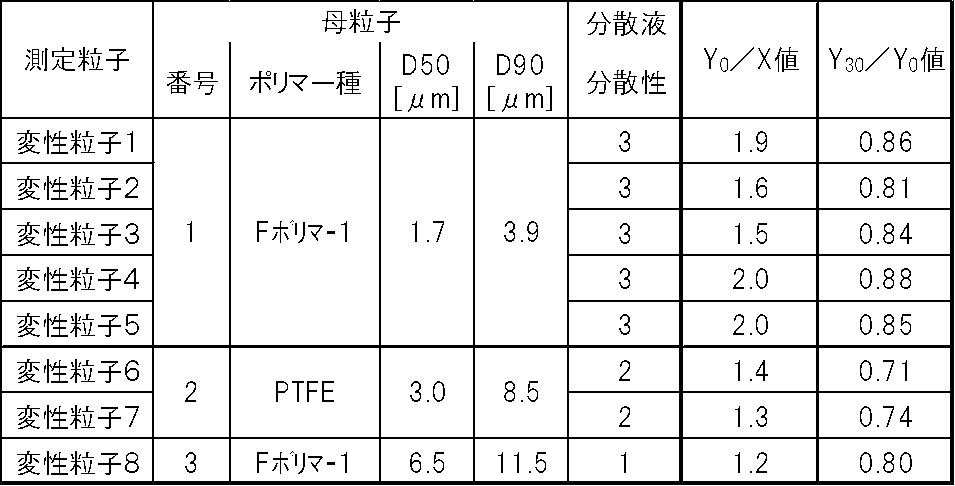
[例3-1]
表面処理直後の変性粒子1と、表面処理から14日経過後の変性粒子1のそれぞれを用いて、次のようにして積層体を製造した。
まず、300gの変性粒子1と、30gのノニオン性界面活性剤(ネオス社製、フタージェント710FL)と、330gのN-メチル-2-ピロリドンとを、横型ボールミルポットに投入した後、15mm径のジルコニアボールを充填して、分散処理することにより分散液1を得た。この分散液1を1日静置した後、ラボスターラー(ヤマト科学社製、LT-500)を用いて5分撹拌した。
次に、熱硬化性変性ポリイミドワニス(ピーアイ研究所社製、溶媒:N-メチルピロリドン、固形分:15質量%)と分散液1とを、熱硬化性変性ポリイミドとFポリマー1とが質量比で80:20となるように混合して液状組成物1を得た。
液状組成物1を厚さ12μmの銅箔の表面に塗布し、窒素雰囲気下において150℃で10分間乾燥し、260℃で10分加熱した後、25℃まで冷却して厚さ10μmのFポリマー1を含むポリマー層を有する積層体(片面銅張積層板)を得た。
[例3-2~3-10]
変性粒子1のかわりに、変性粒子2~8及び母粒子1~2を用いた以外は、例3-1と同様にして、積層体をそれぞれ製造した。なお、母粒子を使用した積層体の製造例においては、製造直後の母粒子を用いた。
<表面平滑性>
積層体のポリマー層表面を目視で観察し、下記基準に従って評価した。
1:筋ムラや粗大粒子によって表面に凹凸が形成されており、光沢がない。
2:粗大粒子による表面の荒れにより、光沢がない。
3:粗大粒子による表面の荒れがわずかに見られるが、光沢がある。
4:表面が平坦であり、光沢がある。
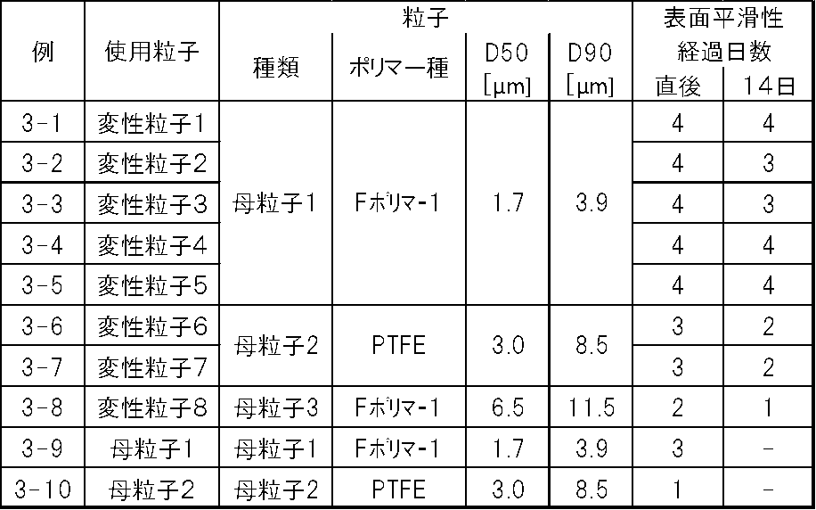
なお、2018年12月5日に出願された日本特許出願2018-228362号の明細書、特許請求の範囲及び要約書の全内容をここに引用し、本発明の明細書の開示として、取り入れるものである。
Claims (15)
- 体積基準累積50%径が0.01~100μmのテトラフルオロエチレン系ポリマーの母粒子を表面処理することにより、該母粒子に極性基が導入された変性粒子を得る、変性粒子の製造方法。
- 前記表面処理が、プラズマ処理又はコロナ処理である、請求項1に記載の製造方法。
- アルゴンガス、ヘリウムガス及び酸素ガスからなる群から選ばれる少なくとも1種を含む雰囲気下、前記母粒子をプラズマ処理する、請求項2に記載の製造方法。
- 前記テトラフルオロエチレン系ポリマーが、該ポリマーに含まれる全単位に対して、テトラフルオロエチレンに基づく単位を99.5モル%以上含む、請求項1~3のいずれか1項に記載の製造方法。
- 前記テトラフルオロエチレン系ポリマーが、該ポリマーに含まれる全単位に対して、テトラフルオロエチレン以外のコモノマーに基づく単位を0.5モル%超含む、請求項1~3のいずれか1項に記載の製造方法。
- 前記テトラフルオロエチレン系ポリマーが、カルボニル基含有基、ヒドロキシ基、エポキシ基、オキセタニル基、アミノ基、ニトリル基及びイソシアネート基からなる群から選ばれる少なくとも1種の官能基を有する、請求項1~5のいずれか1項に記載の製造方法。
- 前記テトラフルオロエチレン系ポリマーが、融点が260~320℃の熱溶融性ポリマーである、請求項1~6のいずれか1項に記載の製造方法。
- 体積基準累積50%径が0.01~100μmのテトラフルオロエチレン系ポリマーの母粒子を表面処理してなる変性粒子であって、
当該変性粒子は、前記母粒子に導入された極性基を有し、そのゼータ電位が前記母粒子のゼータ電位より小さい、変性粒子。 - 前記テトラフルオロエチレン系ポリマーが、カルボニル基含有基、ヒドロキシ基、エポキシ基、オキセタニル基、アミノ基、ニトリル基及びイソシアネート基からなる群から選ばれる少なくとも1種の官能基を有する、請求項8に記載の変性粒子。
- 前記母粒子のゼータ電位をXとし、前記表面処理直後における前記変性粒子のゼータ電位をY0としたとき、Y0/Xが1.3以上である、請求項8又は9に記載の変性粒子。
- 前記表面処理直後における前記変性粒子のゼータ電位をY0とし、前記表面処理終了時から25℃で30日経過後の前記変性粒子のゼータ電位をY30としたとき、Y30/Y0が0.8以上である、請求項8~10のいずれか1項に記載の変性粒子。
- 100gの当該変性粒子を、100gの水に分散させて分散液を調製し、25℃で30日経過後の前記分散液をJIS Z 8801-1:2006の200メッシュ篩に通過させたとき、該篩上に残留する残留物の量が5g以下である、請求項8~11のいずれか1項に記載の変性粒子。
- 請求項8~12のいずれか1項に記載の変性粒子と液状媒体とを含み、前記変性粒子が前記液状媒体に分散した、分散液。
- 請求項8~12のいずれか1項に記載の変性粒子と前記テトラフルオロエチレン系ポリマーとは異なる他のポリマーとを含み、該他のポリマーに前記変性粒子が分散した、組成物。
- 基材と、該基材の表面に設けられ、請求項8~12のいずれか1項に記載の変性粒子から形成された層とを有する、積層体。
Priority Applications (3)
| Application Number | Priority Date | Filing Date | Title |
|---|---|---|---|
| JP2020559235A JP7444072B2 (ja) | 2018-12-05 | 2019-12-03 | 変性粒子の製造方法、変性粒子、分散液、組成物及び積層体 |
| CN201980080578.3A CN113166442A (zh) | 2018-12-05 | 2019-12-03 | 改性粒子的制造方法、改性粒子、分散液、组合物以及层叠体 |
| KR1020217016165A KR102821012B1 (ko) | 2018-12-05 | 2019-12-03 | 변성 입자의 제조 방법, 변성 입자, 분산액, 조성물 및 적층체 |
Applications Claiming Priority (2)
| Application Number | Priority Date | Filing Date | Title |
|---|---|---|---|
| JP2018228362 | 2018-12-05 | ||
| JP2018-228362 | 2018-12-05 |
Publications (1)
| Publication Number | Publication Date |
|---|---|
| WO2020116461A1 true WO2020116461A1 (ja) | 2020-06-11 |
Family
ID=70974710
Family Applications (1)
| Application Number | Title | Priority Date | Filing Date |
|---|---|---|---|
| PCT/JP2019/047265 Ceased WO2020116461A1 (ja) | 2018-12-05 | 2019-12-03 | 変性粒子の製造方法、変性粒子、分散液、組成物及び積層体 |
Country Status (5)
| Country | Link |
|---|---|
| JP (1) | JP7444072B2 (ja) |
| KR (1) | KR102821012B1 (ja) |
| CN (1) | CN113166442A (ja) |
| TW (1) | TWI815999B (ja) |
| WO (1) | WO2020116461A1 (ja) |
Cited By (3)
| Publication number | Priority date | Publication date | Assignee | Title |
|---|---|---|---|---|
| WO2022127116A1 (zh) * | 2020-12-19 | 2022-06-23 | 广东西敦千江粉漆科学研究有限公司 | 一种耐候耐磨疏水助剂的制备方法及应用 |
| JPWO2022149551A1 (ja) * | 2021-01-06 | 2022-07-14 | ||
| EP4203085A1 (en) * | 2021-12-22 | 2023-06-28 | Arkema France | Binder for dry-coated electrode |
Families Citing this family (1)
| Publication number | Priority date | Publication date | Assignee | Title |
|---|---|---|---|---|
| CN113716218B (zh) * | 2021-11-01 | 2022-03-04 | 宁波昌亚新材料科技股份有限公司 | 自热式可降解包装盒及其制备方法 |
Citations (3)
| Publication number | Priority date | Publication date | Assignee | Title |
|---|---|---|---|---|
| JP2004323593A (ja) * | 2003-04-22 | 2004-11-18 | Toyota Industries Corp | フッ素樹脂粉体の改質方法及びフッ素樹脂粉体 |
| JP2007510027A (ja) * | 2003-10-30 | 2007-04-19 | ライプニッツ−インスティチュート フュア ポリマーフォルシュング ドレスデン エーファウ | ラジカル結合ptfeポリマーコンパウンド及びその製造法 |
| JP2013014663A (ja) * | 2011-07-01 | 2013-01-24 | Fuji Electric Co Ltd | ポリマーナノコンポジット樹脂組成物 |
Family Cites Families (1)
| Publication number | Priority date | Publication date | Assignee | Title |
|---|---|---|---|---|
| CN106574055B (zh) | 2014-08-01 | 2019-09-20 | Agc株式会社 | 树脂粉末、其制造方法、复合体、成形体、陶瓷成形体的制造方法、金属层叠板、印刷基板以及预浸料 |
-
2019
- 2019-12-03 JP JP2020559235A patent/JP7444072B2/ja active Active
- 2019-12-03 KR KR1020217016165A patent/KR102821012B1/ko active Active
- 2019-12-03 WO PCT/JP2019/047265 patent/WO2020116461A1/ja not_active Ceased
- 2019-12-03 CN CN201980080578.3A patent/CN113166442A/zh active Pending
- 2019-12-05 TW TW108144458A patent/TWI815999B/zh active
Patent Citations (3)
| Publication number | Priority date | Publication date | Assignee | Title |
|---|---|---|---|---|
| JP2004323593A (ja) * | 2003-04-22 | 2004-11-18 | Toyota Industries Corp | フッ素樹脂粉体の改質方法及びフッ素樹脂粉体 |
| JP2007510027A (ja) * | 2003-10-30 | 2007-04-19 | ライプニッツ−インスティチュート フュア ポリマーフォルシュング ドレスデン エーファウ | ラジカル結合ptfeポリマーコンパウンド及びその製造法 |
| JP2013014663A (ja) * | 2011-07-01 | 2013-01-24 | Fuji Electric Co Ltd | ポリマーナノコンポジット樹脂組成物 |
Cited By (6)
| Publication number | Priority date | Publication date | Assignee | Title |
|---|---|---|---|---|
| WO2022127116A1 (zh) * | 2020-12-19 | 2022-06-23 | 广东西敦千江粉漆科学研究有限公司 | 一种耐候耐磨疏水助剂的制备方法及应用 |
| JPWO2022149551A1 (ja) * | 2021-01-06 | 2022-07-14 | ||
| WO2022149551A1 (ja) * | 2021-01-06 | 2022-07-14 | Agc株式会社 | テトラフルオロエチレン系ポリマー組成物の製造方法、組成物、金属張積層体および延伸シート |
| JP7803286B2 (ja) | 2021-01-06 | 2026-01-21 | Agc株式会社 | テトラフルオロエチレン系ポリマー組成物の製造方法、組成物、金属張積層体および延伸シート |
| EP4203085A1 (en) * | 2021-12-22 | 2023-06-28 | Arkema France | Binder for dry-coated electrode |
| WO2023117595A1 (en) * | 2021-12-22 | 2023-06-29 | Arkema France | Binder for dry-coated electrode |
Also Published As
| Publication number | Publication date |
|---|---|
| TWI815999B (zh) | 2023-09-21 |
| KR20210100092A (ko) | 2021-08-13 |
| JPWO2020116461A1 (ja) | 2021-10-28 |
| KR102821012B1 (ko) | 2025-06-16 |
| TW202031693A (zh) | 2020-09-01 |
| CN113166442A (zh) | 2021-07-23 |
| JP7444072B2 (ja) | 2024-03-06 |
Similar Documents
| Publication | Publication Date | Title |
|---|---|---|
| US11041053B2 (en) | Resin powder, method for its production, composite, molded product, method for producing ceramic molded product, metal laminated plate, printed circuit board and prepreg | |
| JP7396403B2 (ja) | 液状組成物、並びに該液状組成物を使用した、フィルムおよび積層体の製造方法 | |
| JP6954293B2 (ja) | 金属積層板およびその製造方法、ならびにプリント基板の製造方法 | |
| CN109415571B (zh) | 含有氟树脂粉末的液态组合物的制造方法 | |
| JP7444072B2 (ja) | 変性粒子の製造方法、変性粒子、分散液、組成物及び積層体 | |
| JP7205487B2 (ja) | 樹脂パウダーの製造方法、樹脂パウダーおよび積層体の製造方法 | |
| WO2020145133A1 (ja) | フッ素樹脂組成物、フッ素樹脂シート、積層体及び回路用基板 | |
| JP2019104843A (ja) | 樹脂組成物、積層体、金属積層板及びプリント配線板 | |
| JPWO2019131809A1 (ja) | 分散液、金属積層板及びプリント基板の製造方法 | |
| CN115803390B (zh) | 粉体组合物及复合粒子 | |
| KR20230129182A (ko) | 개질 불소 수지 재료, 회로 기판용 재료, 회로 기판용적층체, 회로 기판, 및, 개질 불소 수지 재료의 제조 방법 | |
| WO2020050178A1 (ja) | 分散液の製造方法 |
Legal Events
| Date | Code | Title | Description |
|---|---|---|---|
| 121 | Ep: the epo has been informed by wipo that ep was designated in this application |
Ref document number: 19892563 Country of ref document: EP Kind code of ref document: A1 |
|
| ENP | Entry into the national phase |
Ref document number: 2020559235 Country of ref document: JP Kind code of ref document: A |
|
| ENP | Entry into the national phase |
Ref document number: 20217016165 Country of ref document: KR Kind code of ref document: A |
|
| NENP | Non-entry into the national phase |
Ref country code: DE |
|
| 122 | Ep: pct application non-entry in european phase |
Ref document number: 19892563 Country of ref document: EP Kind code of ref document: A1 |