WO2020116377A1 - 情報処理装置および情報処理方法 - Google Patents
情報処理装置および情報処理方法 Download PDFInfo
- Publication number
- WO2020116377A1 WO2020116377A1 PCT/JP2019/046963 JP2019046963W WO2020116377A1 WO 2020116377 A1 WO2020116377 A1 WO 2020116377A1 JP 2019046963 W JP2019046963 W JP 2019046963W WO 2020116377 A1 WO2020116377 A1 WO 2020116377A1
- Authority
- WO
- WIPO (PCT)
- Prior art keywords
- threshold
- value
- threshold value
- abnormality
- information processing
- Prior art date
- Legal status (The legal status is an assumption and is not a legal conclusion. Google has not performed a legal analysis and makes no representation as to the accuracy of the status listed.)
- Ceased
Links
Images




Classifications
-
- H—ELECTRICITY
- H02—GENERATION; CONVERSION OR DISTRIBUTION OF ELECTRIC POWER
- H02P—CONTROL OR REGULATION OF ELECTRIC MOTORS, ELECTRIC GENERATORS OR DYNAMO-ELECTRIC CONVERTERS; CONTROLLING TRANSFORMERS, REACTORS OR CHOKE COILS
- H02P29/00—Arrangements for regulating or controlling electric motors, appropriate for both AC and DC motors
- H02P29/02—Providing protection against overload without automatic interruption of supply
- H02P29/032—Preventing damage to the motor, e.g. setting individual current limits for different drive conditions
Definitions
- the present invention relates to an information processing device that detects an abnormality in a servo motor mechanism.
- the servo motor mechanism includes a servo motor and a driven device driven by the servo motor.
- the operation of such a servo motor mechanism is controlled by the control device.
- the control device detects an abnormality in the servo motor mechanism, it takes measures such as issuing an alarm.
- Some of such control devices detect an abnormality by monitoring the torque value of a servo motor and detecting a torque value exceeding a normal range. For example, Patent Document 1 discloses that an abnormality is detected when the torque value exceeds a threshold value.
- the servo motor mechanism undergoes changes in coil resistance, thermal deformation, etc. when affected by temperature. Therefore, even when the servo motor mechanism gives a predetermined operation to the driven device by controlling the torque of the servo motor, the torque of the servo motor also changes when the temperature changes. Therefore, the torque value for detecting the abnormality of the servo motor is affected by the temperature.
- Patent Document 1 discloses a system that reduces the influence of the temperature of the torque value by correcting the temperature of the torque value.
- a temperature correction formula for the torque value is created based on the temperature characteristic of the torque value of the drive motor when the robot arm is operated. Then, when the abnormality is detected, the system uses the drive motor or speed reducer temperature measurement value obtained by the temperature sensor to perform temperature correction of the torque value by the temperature correction formula.
- the torque load tends to increase in the running-in state immediately after restarting the operation after suspending the operation of the servo motor mechanism. Therefore, the abnormality may be erroneously detected even when the temperature correction of the torque value as described above is performed. Further, the torque load changes depending on the temperature or the time during which the operation is stopped. In particular, when the temperature is low, the torque load in the operation during the running-in is larger than when the temperature is high. This increase in torque load causes erroneous detection of abnormality.
- One aspect of the present invention is intended to prevent erroneous detection of an abnormality in the torque value after restart of operation.
- the present invention adopts the following configurations in order to solve the above problems.
- the information processing apparatus is that an abnormality that occurs in the operation of a drive mechanism that includes a driven device and a motor that drives the driven device is caused by a torque value of the motor exceeding a threshold value.
- FIG. 6 is a block diagram showing composition of a control system concerning one embodiment of the present invention.
- 6 is a flowchart showing a processing procedure of preparation for performing an abnormality determination of a servo motor mechanism in the control system. It is a graph which shows the relationship between the temperature variable and temperature for calculating the offset amount of the torque value in a running-in period. 6 is a graph showing a relationship between a pause period variable and a pause time for calculating the offset amount. It is a graph which shows the relationship between the number of operations variable and the number of operations for calculating the above-mentioned offset amount. It is a graph which shows the change of the amount of offsets with respect to the number of operations during a break-in period.
- FIG. 8 is a side view showing a ball screw drive stage which is an example of a machine tool showing data necessary for the processing shown in FIG. 7.
- (A)-(c) is a figure which shows the offset correction of the torque value by the said control system.
- FIG. 9 is a diagram for explaining calculation of a torque correction value based on an offset with respect to a reference curve indicating a change in torque value with temperature. It is a figure which shows the relationship of the correction value of a torque value with respect to the frequency
- FIG. 1 is a block diagram showing a schematic configuration of a control system 100 according to this embodiment.
- the control system 100 includes a PLC (programmable logic controller) 1 (information processing device), a servo driver 2, a servo motor mechanism 3 (driving mechanism), and a temperature sensor 4.
- the servo motor mechanism 3 is a control target of the PLC 1, and includes a servo motor 31 and a machine tool 32 (driven part).
- the control system 100 detects an abnormality by the PLC 1 based on the torque value of the servo motor 31. Since the torque value is affected by the temperature, the PLC 1 creates a reference curve in which the reference value of the torque value according to the temperature is plotted. In addition, the PLC 1 also sets a threshold value that defines a normal range around the reference curve. Further, the PLC 1 calculates the offset amount C immediately after the start of a predetermined period (break-in operation period) in which the break-in operation is performed after the servo motor mechanism 3 has stopped operating (pause time) and then restarted. Create the formula of. The offset amount C is the amount by which the torque value that defines the reference curve is offset.
- the PLC 1 calculates a correction value by correcting the torque value during the running-in period during which the abnormality detection is determined, detects the abnormality when the correction value exceeds the threshold value, and detects the abnormality when the correction value is less than or equal to the threshold value. do not do.
- the PLC 1 calculates the offset amount C calculated by applying the acquired variable to the above equation with respect to the torque value specified by the reference curve based on the actual torque value and the temperature of the servo motor 31. Is subtracted from the offset amount X of the torque value. The PLC 1 calculates the correction value in this way.
- the servomotor 31 is a motor that drives a machine tool 32 (driven device), and a rotary encoder for detecting a rotation angle and a rotation angular velocity is attached to the rotation shaft.
- the machine tool 32 is a driven part of a machine such as a robot, and has a mechanism for converting the rotational driving force generated by the servo motor 31 into a predetermined motion.
- the servo driver 2 drives the servo motor 31 by applying torque as optimum drive energy according to the state quantity (rotation angle, rotation angular velocity, etc.) of the servo motor 31 based on the command received from the PLC 1.
- the PLC 1 includes a control unit 11 that gives a control command to the servo driver 2 and a memory 12.
- the control unit 11 generates a command position, a command speed, and a command acceleration for motion control given to the servo driver 2.
- the control unit 11 also includes a pause time recording unit 111 and an operation number counting unit 112.
- the pause time recording unit 111 measures the pause time during which the servo motor mechanism 3 is paused and stores it in the memory 12.
- the operation number counting unit 112 counts the number of times (the number of operations) the predetermined operation performed by the servo motor mechanism 3 is repeated, and stores it in the memory 12.
- the PLC 1 has a data acquisition unit 13, a data correction unit 14 (threshold correction unit), and an abnormality detection unit 15 in order to detect an abnormality in the servomotor mechanism 3.
- the data acquisition unit 13 uses the communication function of the PLC 1 to acquire the torque value of the servo motor 31 from the servo driver 2 and the temperature of the servo motor 31 from the temperature sensor 4.
- the torque value is obtained from the current value output by the servo driver 2 to the servo motor 31.
- the temperature sensor 4 is arranged near the servo motor 31 and detects the temperature of the servo motor 31. Further, the data acquisition unit 13 acquires the above-described pause time and the number of operations stored in the memory 12.
- the data correction unit 14 creates the above-described reference curve and the threshold value, and creates an equation for calculating the offset amount C, prior to the determination of abnormality detection during the running-in period.
- the data correction unit 14 also calculates a correction value during the running-in period.
- the data correction unit 14 corrects the threshold value so that the threshold value used in the running-in period becomes larger than that in the normal operation.
- the abnormality detection unit 15 determines the presence or absence of the servo motor mechanism 3 using the above correction value as a determination standard.
- FIG. 2 is a flowchart showing a processing procedure of preparation for determining whether or not there is an abnormality in the servo motor mechanism in the control system 100.
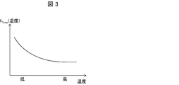
- FIG. 3 is a graph showing the relationship between the temperature variable and the temperature for calculating the offset amount C of the torque value.
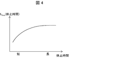
- FIG. 4 is a graph showing the relationship between the pause period variable and the pause time for calculating the offset amount C.
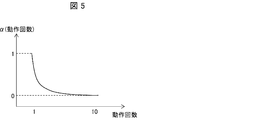
- FIG. 5 is a graph showing the relationship between the operation number variable for calculating the offset amount C and the operation number.
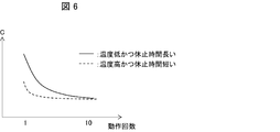
- FIG. 6 is a graph showing changes in the offset amount with respect to the number of operations during the running-in period.
- the data acquisition unit 13 acquires the torque value from the servo driver 2 and the temperature of the servo motor 31 from the temperature sensor 4 during normal operation (step S1).
- the data correction unit 14 creates a reference curve based on the acquired torque value and temperature (step S2).
- the data correction unit 14 plots the torque value corresponding to the temperature when creating the reference curve (for example, the reference curve R shown in FIG. 9A).
- the data correction unit 14 sets a threshold value for the reference curve (step S3).
- the data correction unit 14 sets the upper limit threshold and the lower limit threshold that define the range of the normal value of the torque value based on each value on the reference curve (for example, (a in FIG. 9). ) Threshold TH (upper limit) and threshold TL (lower limit)).
- the data correction unit 14 creates a calculation formula for calculating the offset amount C immediately after the start of the break-in operation (step S4).
- the calculation formula is represented as the following formula as a function of the three variables, the temperature variable f Temp , the pause time variable f Time, and the operation frequency variable ⁇ .
- the offset amount C does not need to be calculated using all of the above three variables, and may be calculated using at least one variable as necessary.
- the value of the variable is set to “1” in the above equation.
- the temperature variable f Temp is represented by a curve that is large at low temperature and small at high temperature, as shown in FIG. Further, the torque value becomes smaller as the pause time becomes shorter and approaches a constant value as the pause time becomes longer. Therefore, as shown in FIG. 4, the pause time variable f Time becomes small for a short pause time. , A large (almost constant value) curve for a long rest time. The torque value decreases as the number of operations increases. Therefore, as shown in FIG. 5, the operation number variable ⁇ is the largest when the number of operations is one, is rapidly reduced when the number of operations is two or three, and is 10 when the number of operations is ten. It is represented by a curve that reaches almost 0 at some time.
- the data correction unit 14 calculates the offset amount C by applying all three variables to the above calculation formula.
- the calculated offset amount C is expressed as a curve with respect to the number of operations as shown in FIG. 6, it can be seen that the dependence of the temperature and the rest time temperature appears clearly.
- the offset amount C has a large value with one operation and a steep decrease in a range with few operations, as shown by the solid line in FIG. It is represented by a sharp curve.
- the offset amount C takes a small value with one operation and has a large change up to two times as shown by the broken line in FIG. After that, it is represented by a gentle curve with little change.
- FIG. 7 is a flowchart showing a processing procedure for abnormality detection in the running-in operation.
- FIG. 8 is a side view showing a ball screw drive stage which is an example of a machine tool showing data necessary for the processing shown in FIG. 7.
- 9A to 9C are diagrams showing torque value offset correction by the control system.
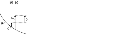
- FIG. 10 is a diagram for explaining that the torque correction value is calculated based on the offset with respect to the reference curve indicating the temperature change of the torque value.
- the pause time measuring unit 111 measures the pause time and stores it in the memory 12.
- the operation number counting unit 112 counts the number of operations of the servo motor mechanism 3.
- the data acquisition unit 13 in the PLC 1 acquires the pause time from the memory 12 (step S11). Further, the data acquisition unit 13 acquires the torque value from the servo driver 2 and the temperature of the servo motor 31 from the temperature sensor 4 in synchronization with the acquisition of the operation number from the operation number counting unit 112 (step). S12).
- the machine tool 32 of the servomotor mechanism 3 is a ball screw drive stage including a ball screw 51 and a stage 52 driven by the ball screw 51 shown in FIG.
- the stage 52 moves from a point P1 (predetermined point) to a certain point P2 (predetermined point) from the point P1 (predetermined point) in the operation of the ball screw driving stage, To obtain the torque value and the temperature.
- the data correction unit 14 calculates the offset amount X of the acquired torque value with respect to the reference value of the torque value corresponding to the acquired temperature in the reference curve created in advance as described above (step S13). ). In addition, the data correction unit 14 calculates the offset amount C based on the above calculation formula using the acquired torque value and temperature (step S14).
- the offset amount C is calculated to be small, and as shown in (b) and (c) of FIG. 9, the temperature becomes low. As the offset amount C increases. Further, as shown in (a) to (c) of FIG. 9, the reference curve R changes to the reference curves R1 to R3 according to the offset amount C, and the threshold R also changes to the threshold value according to the change of the reference curve R. It changes to TH1 to TH3 and thresholds TL1 to TL3, respectively.
- the data correction unit 14 calculates the correction value D of the torque value by subtracting the offset amount C of the same temperature from the acquired offset amount X of the temperature, as shown in FIG. 10 (step S15). In addition, the data correction unit 14 increases the threshold to a value obtained by adding the value of the offset amount C (threshold correction step).
- the abnormality detection unit 15 determines whether or not the calculated correction value exceeds the threshold value (step S16, abnormality detection step).
- step S16 abnormality detection step.
- the abnormality detection unit 15 determines in step S16 that the correction value exceeds the threshold value (YES)
- step S12 If the abnormality detection unit 15 determines in step S16 that the correction value does not exceed the threshold value (NO), the process returns to step S12.
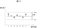
- the calculated correction value is corrected so that it becomes larger than that during normal operation, and the upper limit threshold value THn and the lower limit threshold value TLn are corrected. It is determined whether or not it is in the normal range between. Accordingly, even if the torque value increases in accordance with at least one of the temperature, the rest time, and the number of times of operation during the running-in period, the torque value is corrected based on the offset amount C calculated in advance. Therefore, it is possible to properly determine the abnormality detection of the torque value. Therefore, erroneous detection can be suppressed.
- step S12 it is preferable to use the average of the torque values until the stage 52 moves from point P1 to point P2.
- the offset amount C is calculated using the maximum value of the torque, if abnormality detection is determined based on the correction value calculated by the offset amount C, there is a risk of overlooking a locally existing abnormal portion.
- the average of the torque values it becomes possible to detect a wide range of abnormal places.
- the information processing device is not limited to the PLC 1 and may be a server.
- the data acquisition unit 13 may acquire the pause time and the number of operations from the PLC provided separately.
- the control block (particularly the control unit 11, the data acquisition unit 13, the data correction unit 14, and the abnormality detection unit 15) of the PLC 1 may be realized by a logic circuit (hardware) formed in an integrated circuit (IC chip) or the like. ..
- the control block may be realized by software using a CPU (Central Processing Unit) that executes the instructions of a control program that is software that realizes the functions of the respective units.
- CPU Central Processing Unit
- the PLC 1 includes a CPU, a ROM (Read Only Memory) or a storage device (these are referred to as a “recording medium”), a RAM (Random Access Memory), and the like.
- the ROM records the program and various data so that they can be read by the CPU.
- the RAM expands the above program. Then, the CPU reads the program from the recording medium and executes the program to achieve the object of the present embodiment.
- a “non-transitory tangible medium”, for example, a tape, a disk, a card, a semiconductor memory, a programmable logic circuit, or the like can be used as the recording medium.
- the program may be supplied to the computer via any transmission medium (communication network, broadcast wave, etc.) capable of transmitting the program.
- the present invention can also be realized in the form of a data signal embedded in a carrier wave, in which the above program is embodied by electronic transmission.
- the information processing apparatus detects an abnormality that occurs in the operation of a drive mechanism that includes a driven device and a motor that drives the driven device when the torque value of the motor exceeds a threshold value. And a threshold value correction unit that corrects the threshold value so that the threshold value used in a predetermined period after the drive mechanism restarts operation after a pause period becomes larger than that during normal operation.
- the threshold correction unit may correct the threshold based on the temperature of the motor.
- the threshold correction unit may correct the threshold based on the length of the suspension period.
- the torque value increases when the length of the rest period (rest time) is long. Therefore, by correcting the threshold value based on the pause time, it is possible to early detect an abnormality that may occur immediately after the restart.
- the threshold correction unit may correct the threshold based on the number of operations of the drive mechanism in the predetermined period.
- the torque value is the largest during the first operation immediately after startup, and decreases as the number of operations increases. Therefore, by correcting the threshold value based on the number of operations, it is possible to early detect an abnormality that may occur immediately after restarting.
- the abnormality detection unit may determine the abnormality detection by using the average of the torque values at which the driven device moves between two predetermined points.
- the information processing method detects an abnormality that occurs in the operation of a drive mechanism having a driven device and a motor that drives the driven device when the torque value of the motor exceeds a threshold value. And a threshold value correction step of correcting the threshold value so that the threshold value used in a predetermined period after the drive mechanism restarts the operation after a pause period is larger than that in the normal operation.
Landscapes
- Engineering & Computer Science (AREA)
- Power Engineering (AREA)
- Control Of Electric Motors In General (AREA)
- Numerical Control (AREA)
Abstract
運転再開後のトルク値の異常の誤検知を防止する。PLC(1)は、工作機械(32)と、工作機械(32)を駆動するサーボモータ(31)とを有するサーボモータ機構(3)の動作に生じる異常をサーボモータ(31)のトルク値が閾値を超えたことにより検知する異常検知部(15)と、サーボモータ(31)が休止期間を経て運転を再開した後の所定期間において用いられる前記閾値が通常運転時よりも大きくなるように前記閾値を補正する閾値を補正するデータ補正部(14)と、を備えている。
Description
本発明は、サーボモータ機構の異常を検知する情報処理装置に関する。
サーボモータ機構は、サーボモータおよびサーボモータによって駆動される被駆動装置を含む。このようなサーボモータ機構の動作は、制御装置によって制御される。制御装置は、サーボモータ機構の異常を検知すると、アラームを発するなどの措置を行う。このような制御装置には、サーボモータのトルク値を監視することにより、トルク値が正常範囲を超える値を示すと異常を検知するものがある。例えば、特許文献1には、トルク値が閾値を超えると、異常を検知することが開示されている。
ところで、サーボモータ機構は、温度による影響を受けることにより、コイルの抵抗の変化、熱変形などを生じる。このため、サーボモータ機構は、サーボモータのトルクを制御することにより被駆動装置に所定の動作を与える場合においても、温度が異なると、サーボモータのトルクも異なる。よって、サーボモータの異常を検知するためのトルク値は温度の影響を受ける。
特許文献1には、トルク値の温度補正を行うことにより、トルク値の温度による影響を軽減するシステムが開示されている。このシステムは、減速機の各温度において、ロボットアームを動作させたときの駆動モータのトルク値の温度特性に基づいてトルク値の温度補正式を作成しておく。そして、当該システムは、異常検出時に、温度センサによって得られた駆動モータあるいは減速機温度測定値を用いて、温度補正式によりトルク値の温度補正を行う。
しかしながら、サーボモータ機構の運転を休止させた後に運転を再開した直後の慣らし運転の状態では、トルク負荷が大きくなる傾向にある。このため、上記のようなトルク値の温度補正を行っても異常を誤検知することがある。また、温度または運転を休止した時間によってトルク負荷が変動する。特に、温度が低い場合、温度が高い場合に比べて、慣らし運転時の動作でのトルク負荷がより大きくなる。このトルク負荷の増大が、異常の誤検知の原因となる。
本発明の一態様は、運転再開後のトルク値の異常の誤検知を防止することを目的とする。
本発明は、上述した課題を解決するために、以下の構成を採用する。
すなわち、本開示の一側面に係る情報処理装置は、被駆動装置と、前記被駆動装置を駆動するモータとを有する駆動機構の動作に生じる異常を前記モータのトルク値が閾値を超えたことにより検知する異常検知部と、前記駆動機構が休止期間を経て運転を再開した後の所定期間において用いられる前記閾値が通常運転時よりも大きくなるように前記閾値を補正する閾値補正部と、を備えている。
本発明の一態様によれば、運転再開後のトルク値の異常の誤検知を防止することができる。
以下、本発明の一側面に係る実施の形態(以下、「本実施形態」とも表記する)を、図面に基づいて説明する。
§1 適用例
図1を用いて、本発明が適用される場面の一例について説明する。
図1を用いて、本発明が適用される場面の一例について説明する。
図1は、本実施形態に係る制御システム100の概略構成を示すブロック図である。
図1に示すように、制御システム100は、PLC(programmable logic controller)1(情報処理装置)と、サーボドライバ2と、サーボモータ機構3(駆動機構)と、温度センサ4とを備えている。サーボモータ機構3は、PLC1の制御対象であり、サーボモータ31と、工作機械32(被駆動部)とを含んでいる。
制御システム100は、PLC1によって、サーボモータ31のトルク値に基づいて異常を検知する。トルク値が温度による影響を受けることから、PLC1は、温度に応じたトルク値の基準値をプロットした基準曲線を作成しておく。また、PLC1は、基準曲線を中心にした正常範囲を規定する閾値も併せて設定しておく。また、PLC1は、サーボモータ機構3が運転を休止した時間(休止時間)を経て運転を再開した後の慣らし運転を行う所定期間(慣らし運転期間)の開始直後に、オフセット量Cを算出するための式を作成しておく。オフセット量Cは、基準曲線を規定するトルク値をオフセットさせる量である。
PLC1は、異常検知の判断を行う慣らし運転期間に、トルク値を補正した補正値を算出し、当該補正値が閾値を超えると異常を検知し、当該補正値が閾値以下であると異常を検知しない。PLC1は、補正値の算出において、取得した変数を上記の式に適用して算出したオフセット量Cを、サーボモータ31の実際のトルク値および温度に基づいて基準曲線で特定されるトルク値に対する実際のトルク値のオフセット量Xから減算する。PLC1は、このようにして補正値を算出する。
§2 構成例
図1を用いて、実施形態1に係る制御システム100の構成例について説明する。
図1を用いて、実施形態1に係る制御システム100の構成例について説明する。
サーボモータ31は、工作機械32(被駆動装置)を駆動するモータであり、回転角度および回転角速度を検出するためのロータリエンコーダが回転軸に取り付けられている。工作機械32は、ロボットなどの機械における駆動される部分であり、サーボモータ31が発生する回転駆動力を所定の運動に変換する機構を有している。
サーボドライバ2は、PLC1から受けた指令に基づき、サーボモータ31の状態量(回転角度、回転角速度など)に応じた最適な駆動エネルギーとしてトルクを与えることによってサーボモータ31を駆動する。
PLC1は、サーボドライバ2に制御指令を与える制御部11と、メモリ12とを含んでいる。制御部11は、サーボドライバ2に与えるモーション制御のための指令位置、指令速度および指令加速度を生成する。また、制御部11は、休止時間記録部111と、動作回数計数部112とを含んでいる。休止時間記録部111は、サーボモータ機構3が休止している休止時間を計測してメモリ12に記憶させる。動作回数計数部112は、サーボモータ機構3が行う所定の動作の繰り返しの回数(動作回数)を計数して、メモリ12に記憶させる。
PLC1は、サーボモータ機構3の異常検知を行うために、データ取得部13と、データ補正部14(閾値補正部)と、異常検知部15とを有している。
データ取得部13は、PLC1の通信機能を利用して、サーボドライバ2からサーボモータ31のトルク値を取得するとともに、温度センサ4からサーボモータ31の温度を取得する。なお、トルク値は、サーボドライバ2がサーボモータ31に出力する電流値から求められる。温度センサ4は、サーボモータ31の近傍に配置されており、サーボモータ31の温度を検出する。また、データ取得部13は、メモリ12に記憶されている上記の休止時間および動作回数を取得する。
データ補正部14は、慣らし運転期間における異常検知の判定に先立って、上述の基準曲線の作成および閾値の設定を行うとともに、オフセット量Cを算出する式の作成を行う。また、データ補正部14は、慣らし運転期間において補正値の算出を行う。また、データ補正部14は、慣らし運転期間において用いられる閾値が通常運転時よりも大きくなるように閾値を補正する。
異常検知部15は、上記の補正値を判断基準として、サーボモータ機構3の有無を判定する。
以上のように構成される制御システム100による慣らし運転期間における異常判定の動作について説明する。
まず、異常判定の処理に先立って、オフセット量Cを算出する算出式を作成する処理を行う。
図2は、制御システム100におけるサーボモータ機構の異常有無判定を行うための準備の処理手順を示すフローチャートである。図3は、トルク値のオフセット量Cを算出するための温度変数と温度との関係を示すグラフである。図4は、オフセット量Cを算出するための休止期間変数と休止時間との関係を示すグラフである。図5は、オフセット量Cを算出するための動作回数変数と動作回数との関係を示すグラフである。図6は、慣らし運転期間における動作回数に対するオフセット量の変化を示すグラフである。
図2に示すように、PLC1において、データ取得部13は、通常動作時に、サーボドライバ2からトルク値を取得するとともに、温度センサ4からサーボモータ31の温度を取得する(ステップS1)。
データ補正部14は、取得されたトルク値および温度に基づいて基準曲線を作成する(ステップS2)。データ補正部14は、基準曲線の作成において、温度に対応するトルク値をプロットしていく(例えば、図9の(a)に示す基準曲線R)。
次いで、データ補正部14は、基準曲線に対して閾値を設定する(ステップS3)。データ補正部14は、閾値の設定において、基準曲線における各値を基準とするトルク値の正常値の範囲を規定する上限の閾値および下限の閾値を設定していく(例えば、図9の(a)に示す閾値TH(上限)および閾値TL(下限))。
さらに、データ補正部14は、慣らし運転開始直後のオフセット量Cを算出するための算出式を作成する(ステップS4)。当該算出式は、3つの変数である温度変数fTemp、休止時間変数fTimeおよび動作回数変数αの関数として次式のように表される。
C=f(fTemp,fTime,α)
=α*fTemp*fTime
ここで、オフセット量Cは、上記の3つの変数を全て用いて算出される必要はなく、必要に応じて少なくとも1つの変数が用いられて算出されればよい。オフセット量Cの算出に用いない変数については、上式で当該変数の値が“1”とされる。
=α*fTemp*fTime
ここで、オフセット量Cは、上記の3つの変数を全て用いて算出される必要はなく、必要に応じて少なくとも1つの変数が用いられて算出されればよい。オフセット量Cの算出に用いない変数については、上式で当該変数の値が“1”とされる。
トルク値が、低温状態では大きく、高温状態では小さいことから、温度変数fTempは、図3に示すように、低温では大きく、高温では小さくなる曲線で表される。また、トルク値が、休止時間が短いほど小さく、休止時間が長くなるに連れて一定値に近づくことから、休止時間変数fTimeは、図4に示すように、短い休止時間に対しては小さく、長い休止時間に対しては大きく(ほぼ一定値)なる曲線で表される。トルク値は、動作回数が多くなるほど、小さくなる。ことため、図5に示すように、動作回数変数αは、動作回数が1回であるときに最も大きく、動作回数が2,3回であるときに急激に減少し、動作回数が10回であるときにほぼ0に達する曲線で表される。
データ補正部14は、上記の算出式に3つの変数を全て適用してオフセット量Cを算出する。算出されたオフセット量Cは、図6に示すように、動作回数に対する曲線として表すと、温度および休止時間温の依存性が如実に現れることがわかる。温度が低くかつ休止時間が長い場合、オフセット量Cは、図6において実線にて示すように、動作回数が1回で大きい値をとり、動作回数が少ない範囲で急峻に減少するような傾斜が急な曲線で表される。一方、温度が高くかつ休止時間が短い場合、オフセット量Cは、図6において破線にて示すように、動作回数が1回で小さい値をとり、動作回数が2回まで変化が大きいが、それ以降は変化量が少ない緩やかな曲線で表される。
続いて、サーボモータ機構3の休止期間が終了した再起動以降の処理について説明する。
図7は、慣らし運転における異常検知の処理手順を示すフローチャートである。図8は、図7に示す処理において必要なデータを示す工作機械の一例であるボールねじ駆動ステージを示す側面図である。図9の(a)~(c)は、上記制御システムによるトルク値のオフセット補正を示す図である。図10は、トルク値の温度変化を示す基準曲線に対するオフセットに基づいてトルクの補正値を算出することを説明するための図である。
なお、休止期間には、休止時間計測部111が休止時間を計測して、メモリ12に記憶させている。また、休止時間が終了してサーボモータ機構3の動作が再開した後に続く慣らし運転期間には、動作回数計数部112が、サーボモータ機構3の動作回数を計数する。
図7に示すように、サーボモータ機構3が起動すると、PLC1において、データ取得部13は、メモリ12から休止時間を取得する(ステップS11)。また、データ取得部13は、動作回数計数部112から動作回数を取得するのに同期して、サーボドライバ2からトルク値を取得するとともに、温度センサ4からサーボモータ31の温度を取得する(ステップS12)。
ここで、サーボモータ機構3の工作機械32が、図8に示す、ボールねじ51と、ボールねじ51によって駆動されるステージ52とを備えるボールねじ駆動ステージであるとする。データ取得部13は、このようなボールねじ駆動ステージの動作において、ステージ52が、例えば、ポイントP1(所定点)から、ポイントP3に至るまでのあるポイントP2(所定点)に移動しているときのトルク値と温度とを取得する。
次いで、データ補正部14は、取得されたトルク値の、上述のようにして予め作成された基準曲線における、取得された温度に対応するトルク値の基準値に対するオフセット量Xを算出する(ステップS13)。また、データ補正部14は、取得されたトルク値および温度を用いて上述の算出式に基づいてオフセット量Cを算出する(ステップS14)。
図9の(a)に示すように、慣らし運転期間Tにおいて、温度が高い状態では、オフセット量Cが小さく算出され、図9の(b)および(c)に示すように、温度が低くなる程、オフセット量Cが大きくなる。また、図9の(a)~(c)に示すように、オフセット量Cに応じて基準曲線Rが基準曲線R1~R3にそれぞれ変化し、基準曲線Rの変化に応じて、閾値Rも閾値TH1~TH3および閾値TL1~TL3にそれぞれ変化する。
その後、データ補正部14は、図10に示すように、取得された温度のオフセット量Xから同じ温度のオフセット量Cを減じることによってトルク値の補正値Dを算出する(ステップS15)。また、データ補正部14は、閾値をオフセット量Cの値を加算した値に大きくしておく(閾値補正工程)。
そして、異常検知部15は、算出された補正値が閾値を超えたか否かを判定する(ステップS16,異常検知工程)。異常検知部15は、ステップS16において、補正値が閾値を超えたと判定すると(YES)、異常が発生したことを通知して(ステップS17)、処理をステップS12に戻す。また、異常検知部15は、ステップS16において、補正値が閾値を超えていないと判定すると(NO)、処理をステップS12に戻す。
このような処理を動作回数ごとに繰り返すことにより、図11に示すように、算出された補正値が、通常運転時よりも大きくなるように補正された上限の閾値THnと下限の閾値TLnとの間の正常範囲にあるか否かが判定される。これにより、慣らし運転期間において、温度、休止時間および動作回数の少なくともいずれか1つの値に応じてトルク値が大きくなっても、トルク値が予め算出されたオフセット量Cに基づいて補正される。それゆえ、適正にトルク値の異常検知を判定することができる。したがって、誤検知を抑制することが可能になる。
なお、ステップS12においては、ステージ52がポイントP1からポイントP2に移動するまでのトルク値の平均を用いることが好ましい。オフセット量Cをトルクの最大値を用いて算出した場合、当該オフセット量Cによって算出された補正値を基に異常検知を判定すると、局所的に存在する異常箇所を見逃すおそれがある。これに対し、トルク値の平均を用いるとることにより、広範囲の異常箇所を検知することが可能になる。
また、本発明に係る情報処理装置は、PLC1に限らず、サーバであってもよい。このように構成する場合、データ取得部13は、別途設けられるPLCから休止時間および動作回数を取得するようにしてもよい。
〔ソフトウェアによる実現例〕
PLC1の制御ブロック(特に制御部11、データ取得部13、データ補正部14および異常検知部15)は、集積回路(ICチップ)等に形成された論理回路(ハードウェア)によって実現してもよい。あるいは、当該制御ブロックは、各部の機能を実現するソフトウェアである制御プログラムの命令を実行するCPU(Central Processing Unit)を用いてソフトウェアによって実現してもよい。
PLC1の制御ブロック(特に制御部11、データ取得部13、データ補正部14および異常検知部15)は、集積回路(ICチップ)等に形成された論理回路(ハードウェア)によって実現してもよい。あるいは、当該制御ブロックは、各部の機能を実現するソフトウェアである制御プログラムの命令を実行するCPU(Central Processing Unit)を用いてソフトウェアによって実現してもよい。
後者の場合、PLC1は、CPU、ROM(Read Only Memory)または記憶装置(これらを「記録媒体」と称する)、RAM(Random Access Memory)などを備えている。ROMは、上記プログラムおよび各種データをCPUによって読み取り可能となるように記録する。RAMは、上記プログラムを展開する。そして、CPUが上記プログラムを上記記録媒体から読み取って実行することにより、本実施形態の目的が達成される。
上記記録媒体としては、「一時的でない有形の媒体」、例えば、テープ、ディスク、カード、半導体メモリ、プログラマブルな論理回路などを用いることができる。また、上記プログラムは、該プログラムを伝送可能な任意の伝送媒体(通信ネットワークや放送波等)を介して上記コンピュータに供給されてもよい。
なお、本発明は、上記プログラムが電子的な伝送によって具現化された、搬送波に埋め込まれたデータ信号の形態でも実現され得る。
〔総括〕
本実施形態に係る情報処理装置は、被駆動装置と、前記被駆動装置を駆動するモータとを有する駆動機構の動作に生じる異常を前記モータのトルク値が閾値を超えたことにより検知する異常検知部と、前記駆動機構が休止期間を経て運転を再開した後の所定期間において用いられる前記閾値が通常運転時よりも大きくなるように前記閾値を補正する閾値補正部と、を備えている。
本実施形態に係る情報処理装置は、被駆動装置と、前記被駆動装置を駆動するモータとを有する駆動機構の動作に生じる異常を前記モータのトルク値が閾値を超えたことにより検知する異常検知部と、前記駆動機構が休止期間を経て運転を再開した後の所定期間において用いられる前記閾値が通常運転時よりも大きくなるように前記閾値を補正する閾値補正部と、を備えている。
上記の構成によれば、休止期間後の所定期間における異常検知の誤検知を防ぐことができる。特に、休止期間後の再起動直後には、駆動機構に異常が発生しやすい。したがって、再起動直後(休止期間終了直後)に生じ得る異常を早期に発見することができる。
前記閾値補正部は、前記モータの温度に基づいて前記閾値を補正してもよい。
駆動機構の再起動直後の温度の低い状態では、トルク値が大きくなる。そこで、モータの温度に基づいて閾値を補正することにより、再起動直後に生じ得る異常を早期に発見することができる。
前記閾値補正部は、前記休止期間の長さに基づいて前記閾値を補正してもよい。
トルク値は休止期間の長さ(休止時間)が長いときに大きくなる。そこで、休止時間に基づいて閾値を補正することにより、再起動直後に生じ得る異常を早期に発見することができる。
前記閾値補正部は、前記所定期間における前記駆動機構の動作回数に基づいて前記閾値を補正してもよい。
トルク値は、起動直後の1回目の動作時に最も大きく、動作回数を重ねるにしたがって小さくなる。そこで、動作回数に基づいて閾値を補正することにより、再起動直後に生じ得る異常を早期に発見することができる。
前記異常検知部は、被駆動装置が2つの所定点を移動する前記トルク値の平均を用いて異常検知の判定を行ってもよい。
トルク値の平均を用いるとることにより、広範囲の異常箇所を検知することが可能になる。
本実施形態に係る情報処理方法は、被駆動装置と、前記被駆動装置を駆動するモータとを有する駆動機構の動作に生じる異常を前記モータのトルク値が閾値を超えたことにより検知する異常検知工程と、前記駆動機構が休止期間を経て運転を再開した後の所定期間において用いられる前記閾値が通常運転時よりも大きくなるように前記閾値を補正する閾値補正工程と、を含んでいる。
本発明は上述した実施形態に限定されるものではなく、請求項に示した範囲で種々の変更が可能であり、実施形態にそれぞれ開示された技術的手段を適宜組み合わせて得られる実施形態についても本発明の技術的範囲に含まれる。
1 PLC
3 サーボモータ機構(駆動機構)
4 温度センサ
14 データ補正部(閾値補正部)
15 異常検知部
31 サーボモータ(モータ)
32 工作機械(被駆動装置)
3 サーボモータ機構(駆動機構)
4 温度センサ
14 データ補正部(閾値補正部)
15 異常検知部
31 サーボモータ(モータ)
32 工作機械(被駆動装置)
Claims (6)
- 被駆動装置と、前記被駆動装置を駆動するモータとを有する駆動機構の動作に生じる異常を前記モータのトルク値が閾値を超えたことにより検知する異常検知部と、
前記駆動機構が休止期間を経て運転を再開した後の所定期間において用いられる前記閾値が通常運転時よりも大きくなるように前記閾値を補正する閾値補正部と、を備えている情報処理装置。 - 前記閾値補正部は、前記モータの温度に基づいて前記閾値を補正する請求項1に記載の情報処理装置。
- 前記閾値補正部は、前記休止期間の長さに基づいて前記閾値を補正する請求項1または2に記載の情報処理装置。
- 前記閾値補正部は、前記所定期間における前記駆動機構の動作回数に基づいて前記閾値を補正する請求項1から3のいずれか1項に記載の情報処理装置。
- 前記異常検知部は、被駆動装置が2つの所定点を移動する前記トルク値の平均を用いて異常検知の判定を行う請求項1から4のいずれか1項に記載の情報処理装置。
- 被駆動装置と、前記被駆動装置を駆動するモータとを有する駆動機構の動作に生じる異常を前記モータのトルク値が閾値を超えたことにより検知する異常検知工程と、
前記駆動機構が休止期間を経て運転を再開した後の所定期間において用いられる前記閾値が通常運転時よりも大きくなるように前記閾値を補正する閾値補正工程と、を含んでいる情報処理方法。
Applications Claiming Priority (2)
| Application Number | Priority Date | Filing Date | Title |
|---|---|---|---|
| JP2018-230161 | 2018-12-07 | ||
| JP2018230161A JP7192458B2 (ja) | 2018-12-07 | 2018-12-07 | 情報処理装置、情報処理方法および情報処理プログラム |
Publications (1)
| Publication Number | Publication Date |
|---|---|
| WO2020116377A1 true WO2020116377A1 (ja) | 2020-06-11 |
Family
ID=70975117
Family Applications (1)
| Application Number | Title | Priority Date | Filing Date |
|---|---|---|---|
| PCT/JP2019/046963 Ceased WO2020116377A1 (ja) | 2018-12-07 | 2019-12-02 | 情報処理装置および情報処理方法 |
Country Status (2)
| Country | Link |
|---|---|
| JP (1) | JP7192458B2 (ja) |
| WO (1) | WO2020116377A1 (ja) |
Cited By (1)
| Publication number | Priority date | Publication date | Assignee | Title |
|---|---|---|---|---|
| CN121176929A (zh) * | 2025-09-30 | 2025-12-23 | 东软医疗系统股份有限公司 | 扫描床的运动保护方法、电子设备及医疗影像设备 |
Citations (3)
| Publication number | Priority date | Publication date | Assignee | Title |
|---|---|---|---|---|
| JP2000107987A (ja) * | 1998-07-27 | 2000-04-18 | Hitachi Metals Ltd | 工具異常検出装置 |
| JP2007286904A (ja) * | 2006-04-17 | 2007-11-01 | Fanuc Ltd | 電動機の制御装置及び制御方法 |
| JP2018148690A (ja) * | 2017-03-06 | 2018-09-20 | 株式会社デンソー | モータ制御装置 |
Family Cites Families (1)
| Publication number | Priority date | Publication date | Assignee | Title |
|---|---|---|---|---|
| JP6542713B2 (ja) * | 2016-06-09 | 2019-07-10 | ファナック株式会社 | 異常負荷検出の閾値を学習する機械学習器,数値制御装置および機械学習方法 |
-
2018
- 2018-12-07 JP JP2018230161A patent/JP7192458B2/ja active Active
-
2019
- 2019-12-02 WO PCT/JP2019/046963 patent/WO2020116377A1/ja not_active Ceased
Patent Citations (3)
| Publication number | Priority date | Publication date | Assignee | Title |
|---|---|---|---|---|
| JP2000107987A (ja) * | 1998-07-27 | 2000-04-18 | Hitachi Metals Ltd | 工具異常検出装置 |
| JP2007286904A (ja) * | 2006-04-17 | 2007-11-01 | Fanuc Ltd | 電動機の制御装置及び制御方法 |
| JP2018148690A (ja) * | 2017-03-06 | 2018-09-20 | 株式会社デンソー | モータ制御装置 |
Cited By (1)
| Publication number | Priority date | Publication date | Assignee | Title |
|---|---|---|---|---|
| CN121176929A (zh) * | 2025-09-30 | 2025-12-23 | 东软医疗系统股份有限公司 | 扫描床的运动保护方法、电子设备及医疗影像设备 |
Also Published As
| Publication number | Publication date |
|---|---|
| JP2020092567A (ja) | 2020-06-11 |
| JP7192458B2 (ja) | 2022-12-20 |
Similar Documents
| Publication | Publication Date | Title |
|---|---|---|
| US20170102000A1 (en) | Motor drive device capable of informing malfunction in operation of fan, and method thereof | |
| TWI660162B (zh) | 馬達控制裝置及使用該控制裝置之馬達裝置 | |
| JP4109280B2 (ja) | サーボモータによって駆動制御される可動部を有する機械 | |
| US11465286B2 (en) | Robot control apparatus, maintenance management method, and maintenance management program | |
| CN110174873B (zh) | 伺服控制装置 | |
| US10081088B2 (en) | Main spindle failure detection device for machine tool and method of detecting main spindle failure | |
| JP2007286904A (ja) | 電動機の制御装置及び制御方法 | |
| US9122258B2 (en) | Motor control device | |
| KR20170139608A (ko) | 고장 진단 장치 및 고장 진단 방법 | |
| CN102445920A (zh) | 用于驱动单元用的碰撞识别的方法 | |
| US8242734B2 (en) | Controller of spindle provided with encoder | |
| US10639759B2 (en) | Load state diagnosis device and load state diagnosis method for servomotor | |
| US9356550B2 (en) | Motor controller having abnormality detection function of power transmission unit between motor and main shaft | |
| JP7192458B2 (ja) | 情報処理装置、情報処理方法および情報処理プログラム | |
| JP6763286B2 (ja) | モータ制御システム | |
| US20210181730A1 (en) | Robot system and control device for robot | |
| CN109643113B (zh) | 故障诊断装置及故障诊断方法 | |
| CN120262319A (zh) | 一种后视镜电机的堵转保护方法及装置 | |
| JP5498363B2 (ja) | 制御システムコントローラ | |
| JP7021656B2 (ja) | 情報処理装置、情報処理方法、及び情報処理プログラム | |
| JP4240195B2 (ja) | エンコーダ検出位置データのビット誤り検出・推定方法およびエンコーダビット誤り検出・推定機能付acサーボドライバ並びにモータ | |
| US20080129549A1 (en) | System and method for encoder failure detection | |
| JP2020163557A (ja) | ねじ締め不良判定装置、ねじ締め装置、ねじ締め不良判定方法、および制御プログラム | |
| JP7110845B2 (ja) | 情報処理装置及び情報処理方法 | |
| JP6802013B2 (ja) | 位置制御システム |
Legal Events
| Date | Code | Title | Description |
|---|---|---|---|
| 121 | Ep: the epo has been informed by wipo that ep was designated in this application |
Ref document number: 19894140 Country of ref document: EP Kind code of ref document: A1 |
|
| NENP | Non-entry into the national phase |
Ref country code: DE |
|
| 122 | Ep: pct application non-entry in european phase |
Ref document number: 19894140 Country of ref document: EP Kind code of ref document: A1 |