WO2020116191A1 - 内燃機関のシール構造 - Google Patents
内燃機関のシール構造 Download PDFInfo
- Publication number
- WO2020116191A1 WO2020116191A1 PCT/JP2019/045738 JP2019045738W WO2020116191A1 WO 2020116191 A1 WO2020116191 A1 WO 2020116191A1 JP 2019045738 W JP2019045738 W JP 2019045738W WO 2020116191 A1 WO2020116191 A1 WO 2020116191A1
- Authority
- WO
- WIPO (PCT)
- Prior art keywords
- seal
- piston member
- housing
- main piece
- piece
- Prior art date
- Legal status (The legal status is an assumption and is not a legal conclusion. Google has not performed a legal analysis and makes no representation as to the accuracy of the status listed.)
- Ceased
Links
Images


Classifications
-
- F—MECHANICAL ENGINEERING; LIGHTING; HEATING; WEAPONS; BLASTING
- F01—MACHINES OR ENGINES IN GENERAL; ENGINE PLANTS IN GENERAL; STEAM ENGINES
- F01C—ROTARY-PISTON OR OSCILLATING-PISTON MACHINES OR ENGINES
- F01C19/00—Sealing arrangements in rotary-piston machines or engines
- F01C19/02—Radially-movable sealings for working fluids
-
- F—MECHANICAL ENGINEERING; LIGHTING; HEATING; WEAPONS; BLASTING
- F02—COMBUSTION ENGINES; HOT-GAS OR COMBUSTION-PRODUCT ENGINE PLANTS
- F02B—INTERNAL-COMBUSTION PISTON ENGINES; COMBUSTION ENGINES IN GENERAL
- F02B53/00—Internal-combustion aspects of rotary-piston or oscillating-piston engines
-
- F—MECHANICAL ENGINEERING; LIGHTING; HEATING; WEAPONS; BLASTING
- F16—ENGINEERING ELEMENTS AND UNITS; GENERAL MEASURES FOR PRODUCING AND MAINTAINING EFFECTIVE FUNCTIONING OF MACHINES OR INSTALLATIONS; THERMAL INSULATION IN GENERAL
- F16J—PISTONS; CYLINDERS; SEALINGS
- F16J15/00—Sealings
- F16J15/02—Sealings between relatively-stationary surfaces
- F16J15/06—Sealings between relatively-stationary surfaces with solid packing compressed between sealing surfaces
-
- Y—GENERAL TAGGING OF NEW TECHNOLOGICAL DEVELOPMENTS; GENERAL TAGGING OF CROSS-SECTIONAL TECHNOLOGIES SPANNING OVER SEVERAL SECTIONS OF THE IPC; TECHNICAL SUBJECTS COVERED BY FORMER USPC CROSS-REFERENCE ART COLLECTIONS [XRACs] AND DIGESTS
- Y02—TECHNOLOGIES OR APPLICATIONS FOR MITIGATION OR ADAPTATION AGAINST CLIMATE CHANGE
- Y02T—CLIMATE CHANGE MITIGATION TECHNOLOGIES RELATED TO TRANSPORTATION
- Y02T10/00—Road transport of goods or passengers
- Y02T10/10—Internal combustion engine [ICE] based vehicles
- Y02T10/12—Improving ICE efficiencies
Definitions
- the present disclosure relates to a seal structure for an internal combustion engine.
- the present disclosure provides a seal structure that can improve the sealing performance of the combustion chamber.
- a seal structure that maintains airtightness in the combustion chamber of an internal combustion engine.
- the internal combustion engine includes a housing, a first piston member rotatably supported in the housing, and a second piston member rotatably supported in the housing.
- a combustion chamber for burning fuel is formed by the housing, the first piston member, and the second piston member.
- the first piston member has an annular first rotating body and a first wall surface member that constitutes a wall surface in the circumferential direction of the combustion chamber.
- the second piston member includes an annular second rotating body and a second wall surface member that forms a wall surface in the circumferential direction of the combustion chamber. The second rotating body is arranged adjacent to the first rotating body in the axial direction.
- the second rotating body has a facing surface that faces the first rotating body.
- the first wall surface member has a first side facing the facing surface of the second piston member, a second side facing the housing, and a corner portion where the first side and the second side intersect.
- the seal structure has a first apex seal and a second apex seal which is a member separate from the first apex seal.
- the first apex seal is held on the first side and is in contact with the second piston member.
- the first apex seal has a longitudinally divided structure including a first main piece and a first side piece.
- the second apex seal is held on the second side and is in contact with the housing.
- the second apex seal has a structure divided in the longitudinal direction having a second main piece and a second side piece.
- the first apex seal divided in the longitudinal direction and the second apex seal divided in the longitudinal direction are configured as separate members, and the first apex seal and the second apex seal are combined to form a seal structure. .. Even if the required seal distance between the two piston members varies depending on the object, the length of the apex seal can be changed and can follow up, whereby the sealing performance of the combustion chamber can be improved.
- the first main piece in the first apex seal, is arranged on the corner side of the first wall member, and in the second apex seal, the second main piece is arranged on the corner side of the first wall member. It is located in.
- the corner sealing performance can be improved.
- the second main piece has a sliding surface that comes into contact with the housing and an opposite surface on the opposite side of the sliding surface.
- the first main piece is in contact with the opposite surface. Accordingly, it is possible to reliably realize the structure in which the first main piece and the second main piece seal the corners.
- the second main piece abuts and seals between the second piston member and the housing
- the first outer peripheral seal abuts the second side piece and the gap between the first piston member and the housing.
- a second outer peripheral seal for sealing is provided.
- the above seal structure further includes a mating face seal that seals the inner peripheral portion of the combustion chamber. Thereby, the sealing property can be further improved.
- the sealing performance of the combustion chamber can be improved.
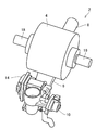
- FIG. 1 is a perspective view showing the configuration of the internal combustion engine of the embodiment.
- the internal combustion engine of the embodiment is a rotary piston type engine 2.
- fuel for the engine 2 for example, gas, gasoline, light oil, or the like is used.
- the engine 2 includes a housing 4, an intake pipe 6, an exhaust pipe 8, an injector 10, a throttle motor 14, a first output shaft 16, and a second output shaft 18.
- One end of the intake pipe 6 is connected to the intake port (not shown) of the housing 4.
- An air cleaner (not shown) is connected to the other end of the intake pipe 6, for example. The air cleaner removes foreign matter from the air sucked from the outside of the engine 2. During operation of the engine 2, the air taken in from the air cleaner flows through the intake pipe 6. The air flowing through the intake pipe 6 flows into the intake port of the housing 4.
- the intake pipe 6 is provided with a throttle valve that limits the flow rate of air flowing through the intake pipe 6.
- the throttle motor 14 adjusts the opening of the throttle valve.
- the injector 10 is provided upstream of the throttle valve of the intake pipe 6 and injects fuel (for example, gas) into the intake pipe 6.
- fuel for example, gas
- the injected fuel is mixed with air in the intake pipe 6 and flows into the intake port of the housing 4.
- the outer peripheral part of the housing 4 is formed in a cylindrical shape as shown in FIG. 1, and the inner peripheral part is also formed in a cylindrical shape.
- the housing 4 accommodates therein a first piston member connected to the first output shaft 16 and a second piston member connected to the second output shaft 18.
- One end of the exhaust pipe 8 is connected to the exhaust port (not shown) of the housing 4.
- An exhaust treatment device (not shown) is connected to the other end of the exhaust pipe 8, for example.
- Exhaust gas generated by combustion in the housing 4 while the engine 2 is operating flows from the exhaust port of the housing 4 to the exhaust pipe 8.
- Exhaust gas flowing through the exhaust pipe 8 is purified by the exhaust treatment device and is discharged to the outside of the engine 2.
- Both the first output shaft 16 and the second output shaft 18 rotate due to combustion of fuel in the housing 4.
- the first output shaft 16 and the second output shaft 18 are connected to, for example, a rotating shaft of a motor generator (not shown).
- This motor generator is, for example, a three-phase AC rotating electric machine.
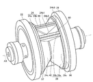
- FIG. 2 is a diagram showing an example of a configuration of a piston member provided inside the engine 2. An example of the internal structure of the engine 2 will be described with reference to FIG.
- the first piston member 24 and the second piston member 28 are combined and housed in the housing 4.
- the first piston member 24 includes a first rotating body 24a and a first wall surface member 24b.
- the second piston member 28 includes a second rotating body 28a and a second wall surface member 28b.
- the first piston member 24 and the second piston member 28 are rotatably supported by the housing 4.
- the first rotary body 24a and the second rotary body 28a each have an annular shape.
- the first rotary body 24a and the second rotary body 28a have the same rotation center axis AX indicated by the alternate long and short dash line in FIG.
- the first rotary body 24a and the second rotary body 28a are rotatable about the rotation center axis AX.
- the first rotating body 24a and the second rotating body 28a are provided such that one end surface of the first rotating body 24a and one end surface of the second rotating body 28a face each other in the axial direction.
- the first rotary body 24a and the second rotary body 28a are arranged adjacent to each other in the axial direction.
- a direction parallel to the rotation center axis AX is referred to as an axial direction
- a direction along a circumference centered on the rotation center axis AX is referred to as a circumferential direction
- a direction orthogonal to the rotation center axis AX is referred to as the radial direction.
- the side closer to the rotation center axis AX in the radial direction is called the inner side
- the side away from the rotation center axis AX is called the outer side.
- the first rotating body 24a is formed to have a sloped portion 24c in a cross section including the rotation center axis AX.
- the second rotating body 28a is formed to have a sloped portion 28c in a cross section including the rotation center axis AX.
- a concave portion having a V-shaped cross section is circumferentially formed between the first rotating body 24a and the second rotating body 28a.
- the inclined surface portion 24c of the first rotary body 24a faces the second rotary body 28a.
- the inclined surface portion 28c of the second rotating body 28a faces the first rotating body 24a.
- the inclined surface portion 28c corresponds to the facing surface in the embodiment.
- the first wall member 24b is provided so as to extend radially outward from the slope portion 24c of the first rotating body 24a and axially extend toward the slope portion 28c of the second rotating body 28a.
- the first wall surface member 24b is composed of two triangular plate-shaped members.
- the two triangular plate-shaped members of the first wall member 24b are arranged at positions symmetrical to each other with respect to the rotation center axis AX.
- the second wall member 28b is provided so as to extend radially outward from the sloped portion 28c of the second rotary body 28a and axially toward the sloped portion 24c of the first rotary body 24a.
- the second wall surface member 28b is composed of two triangular plate members having the same shape as the plate member forming the first wall member 24b.
- the two triangular plate-shaped members of the second wall surface member 28b are arranged at positions symmetrical to each other with respect to the rotation center axis AX. In FIG. 2, only one of the two plate-shaped members of the second wall surface member 28b is shown.
- the triangular plate-shaped members of the first wall surface member 24b and the second wall surface member 28b are both the first rotary member 24a and the first rotary member 24a when the first piston member 24 and the second piston member 28 are housed in the housing 4. It is formed so as to match the triangular sectional shape formed by the V-shaped concave portion between the two rotating bodies 28a and the inner peripheral surface of the housing 4.
- the first wall member 24b has a first side 24b1 forming one side of the triangle, a second side 24b2 forming one side of the triangle, and a corner portion 24b3 where the first side 24b1 and the second side 24b2 intersect. It has a rectangular shape.
- the first side 24b1 of the first wall member 24b faces the inclined surface portion 28c of the second rotating body 28a.
- the second side 24b2 of the first wall member 24b faces the inner peripheral surface of the housing 4.
- the first wall member 24b is fixed to the inclined surface portion 24c of the first rotating body 24a on the other side of the triangle.
- the second wall member 28b has the same rectangular shape as the first wall member 24b.
- One side of the triangle of the second wall member 28b faces the inclined surface portion 24c of the first rotating body 24a.
- One side of the triangle of the second wall member 28 b faces the inner peripheral surface of the housing 4.
- the second wall member 28b is fixed to the inclined surface portion 28c of the second rotating body 28a on the other side of the triangle.
- the first output shaft 16 is connected to the first rotating body 24a so that the centers of rotation coincide with each other.
- the one-way clutch 22 is provided between the first rotating body 24 a and the housing 4. The one-way clutch 22 allows rotation of the first rotating body 24a only in a predetermined rotation direction within the housing 4, and suppresses rotation in a direction opposite to the predetermined rotation direction.
- the second output shaft 18 is connected to the second rotating body 28a so that the centers of rotation coincide with each other.
- the one-way clutch 26 is provided between the second rotating body 28 a and the housing 4. The one-way clutch 26 allows rotation of the second rotating body 28a only in a predetermined rotation direction within the housing 4, and suppresses rotation in a direction opposite to the predetermined rotation direction.
- the first wall member 24b holds the apex seal 80.
- the second wall surface member 28b holds the apex seal 80.
- the second rotating body 28a holds an annular outer peripheral seal 96.
- the first rotating body 24a holds an annular outer peripheral seal 97.
- a mating face seal 40 is provided between the first rotary body 24a and the second rotary body 28a. Details of these seals will be described later.
- FIG. 3 is a schematic diagram for explaining the operations of the combustion chambers A to D and the engine 2.
- FIG. 3 schematically shows a cross section of the central portion of the housing 4 (for example, a contact portion between the first rotating body 24a and the second rotating body 28a) orthogonal to the rotation center axis AX.
- the housing 4 in the housing 4, the housing 4, the first piston member 24, and the second piston member 28 form four combustion chambers A to D for burning fuel.
- the combustion chambers A to D respectively include an inner peripheral surface of the housing 4, a first wall surface member 24b and a sloped surface portion 24c of the first piston member 24, a second wall surface member 28b and a sloped surface portion 28c of the second piston member 28, respectively. Stipulated by The first wall surface member 24b and the second wall surface member 28b form wall surfaces in the circumferential direction of the combustion chambers A to D. The two combustion chambers adjacent to each other in the circumferential direction are partitioned by the first wall surface member 24b and the second wall surface member 28b.
- the one-way clutches 22 and 26 shown in FIG. 2 suppress the counterclockwise rotation of the first piston member 24 and the second piston member 28 in FIG. 3 and allow the clockwise rotation.
- an expansion stroke occurs in which a mixture of compressed air and fuel is ignited by self-ignition. That is, when the fuel burns in the combustion chamber A, the counterclockwise movement of the first piston member 24 is suppressed by the one-way clutch 22, so that the rotational position of the first piston member 24 is maintained and the second piston member 28 is maintained. Only rotates in the direction of the dashed arrow, and the volume of the combustion chamber A increases as the gas in the combustion chamber A expands.
- the expanded exhaust gas is discharged through the exhaust pipe 8 in the exhaust stroke. That is, when the second piston member 28 rotates in the direction of the dashed arrow due to the combustion of the fuel in the combustion chamber A, the rotational position of the first piston member 24 is maintained, and the volume of the combustion chamber B decreases. At this time, the combustion chamber B communicates with the exhaust pipe 8. Therefore, the exhaust gas in the combustion chamber B is discharged to the exhaust pipe 8 as the volume of the combustion chamber B decreases.
- the combustion chamber C shown in FIG. 3 has an intake stroke in which a mixture of air and fuel is sucked from the intake pipe 6. That is, when the second piston member 28 rotates in the direction of the dashed arrow due to the combustion of fuel in the combustion chamber A, the rotational position of the first piston member 24 is maintained, and the volume of the combustion chamber C increases. At this time, the combustion chamber C communicates with the intake pipe 6 while the second piston member 28 rotates in the direction of the dashed arrow. Therefore, as the volume of the combustion chamber C increases, the air-fuel mixture is sucked into the combustion chamber C from the intake pipe 6.
- the air-fuel mixture sucked from the intake pipe 6 is compressed. That is, when the second piston member 28 rotates in the direction of the dashed arrow due to the combustion of fuel in the combustion chamber A, the rotational position of the first piston member 24 is maintained, and the volume of the combustion chamber D decreases. At this time, since the combustion chamber D does not communicate with either the intake pipe 6 or the exhaust pipe 8, the volume of the combustion chamber D is reduced and the air-fuel mixture in the combustion chamber D is compressed.
- the engine 2 operates by alternately rotating the first piston member 24 and the second piston member 28 each time combustion occurs in any of the combustion chambers A to D.
- FIG. 4 is a sectional view of the first piston member 24 and the second piston member 28.
- FIG. 4 shows a cross section of the first piston member 24 and the second piston member 28 including the rotation center axis AX shown in FIG. 2 and passing through the first wall surface member 24b of the first piston member 24.
- the left-right direction in the figure is the axial direction.
- the first piston member 24 and the second piston member 28 are arranged side by side in the axial direction.
- the first piston member 24 and the second piston member 28 are connected via a bearing 100 and are configured to be rotatable relative to each other.
- a lubricating oil passage 241 is formed in the first piston member 24.
- a lubricating oil passage 281 is formed in the second piston member 28. The lubricating oil passage 241 and the lubricating oil passage 281 communicate with each other.
- the sealing structure for hermetically sealing the combustion chambers AD includes apex seals 50 and 80, a mating face seal 40, a corner seal 60, and outer peripheral seals 96 and 97. There is.
- the apex seal 50 is held by the first wall surface member 24b of the first piston member 24.
- An accommodation groove 245 is formed in the first wall member 24b, and the apex seal 50 is accommodated in the accommodation groove 245.
- the housing groove 245 is formed on the edge of the first wall member 24b that faces the inclined surface portion 28c of the second piston member 28, that is, on the first side 24b1 of the first wall member 24b shown in FIG.
- the apex seal 50 is held on the first side 24b1 of the first wall surface member 24b.
- the apex seal 50 corresponds to the first apex seal in the embodiment.
- the apex seal 80 is provided as a separate member from the apex seal 50.
- the apex seal 80 is held by the first wall surface member 24b of the first piston member 24.
- An accommodation groove 248 is formed in the first wall member 24b, and the apex seal 80 is accommodated in the accommodation groove 248.
- the housing groove 248 is formed on the outer peripheral edge of the first wall surface member 24b facing the inner peripheral surface of the housing 4, that is, on the second side 24b2 of the first wall surface member 24b shown in FIG.
- the apex seal 80 is held by the second side 24b2 of the first wall surface member 24b.
- the apex seal 80 corresponds to the second apex seal in the embodiment.
- the mating face seal 40 has an annular shape as shown in FIG. As shown in FIG. 4, the mating surface seal 40 is arranged radially inward of the inclined surface portion 28c of the second piston member 28. The mating face seal 40 is arranged radially inward of the first wall member 24b. Therefore, the mating face seal 40 is arranged radially inward of the combustion chambers A to D and seals the inner peripheral portions of the combustion chambers A to D. The mating face seal 40 suppresses gas leakage from the combustion chambers A to D to the inner peripheral side.
- the mating face seal 40 is held by the first piston member 24.
- An annular groove is formed in the first piston member 24, and the mating face seal 40 is accommodated in the annular groove.
- the mating face seal 40 is in close contact with the second piston member 28. With the relative rotation of the first piston member 24 and the second piston member 28, the mating face seal 40 slides with respect to the second piston member 28.
- the corner seal 60 is arranged at the intersection of the mating face seal 40 and the apex seal 50.
- the first piston member 24 is formed with a housing recess at the radially inner end of the first wall member 24b, and the corner seal 60 is housed in the housing recess. Therefore, the corner seal 60 is held by the first piston member 24 at the radially inner end of the first wall member 24b.
- a spring member 73 is provided on the bottom surface of the accommodation recess, and the spring member 73 urges the corner seal 60 toward the outside of the accommodation recess.
- the corner seal 60 has a sealing surface 61.
- the sealing surface 61 is in contact with the second piston member 28. As the first piston member 24 and the second piston member 28 rotate relative to each other, the sealing surface 61 slides on the second piston member 28. Since the spring member 73 biases the corner seal 60, the adhesion of the seal surface 61 to the second piston member 28 is secured.
- the corner seal 60 is formed with a recess in which a part of the sealing surface 61 is depressed. A part of the mating face seal 40 is arranged in the recess, and the mating face seal 40 is engaged with the corner seal 60. A slit-shaped insertion portion is formed on the radially outer surface of the corner seal 60. The apex seal 50 is inserted into this insertion portion, and the apex seal 50 is engaged with the corner seal 60. The corner seal 60 connects the apex seal 50 and the mating face seal 40 so as not to generate a break in the seal.
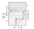
- FIG. 5 is an enlarged sectional view showing the seal structure.
- the apex seal 50 is divided into a main piece 51 and a side piece 52 at an end portion in the longitudinal direction thereof by an inclined surface inclined with respect to the longitudinal direction.
- the apex seal 50 has a structure that is divided in the longitudinal direction and has a main piece 51 and a side piece 52.
- the main piece 51 corresponds to the first main piece in the embodiment.
- the side piece 52 corresponds to the first side piece in the embodiment.
- the length of the side piece 52 in the longitudinal direction of the apex seal 50 is considerably shorter than the length of the main piece 51.
- the main piece 51 is arranged outside and the side piece 52 is arranged inside.
- the main piece 51, instead of the side piece 52, is arranged at the corner 24b3 of the first wall member 24b.
- the bow-shaped spring portions 53 and 54 are installed on the bottom side of the housing groove 245 with respect to the main piece 51 and the side piece 52.
- the spring portions 53 and 54 urge the main piece 51 and the side piece 52 toward the outside of the housing groove 245, that is, toward the second piston member 28. Thereby, the main piece 51 and the side piece 52 are in contact with the second piston member 28, more specifically, the inclined surface portion 28c of the second rotating body 28a.
- the spring portions 53 and 54 also urge the main piece 51 and the side piece 52 toward both ends in the longitudinal direction.
- the apex seal 80 is divided at its longitudinal end portion into a main piece 81 and a side piece 82 by an inclined surface that is inclined with respect to the longitudinal direction.
- the apex seal 80 has a structure that is divided in the longitudinal direction and has a main piece 81 and a side piece 82.
- the main piece 81 corresponds to the second main piece in the embodiment.
- the side piece 82 corresponds to the second side piece in the embodiment.
- the length of the side piece 82 in the longitudinal direction of the apex seal 80 is considerably shorter than the length of the main piece 81.
- the main piece 81 In the axial direction (the left-right direction in the drawing in FIG. 5), the main piece 81 is arranged near the second piston member 28, and the side piece 82 is arranged apart from the second piston member 28.
- the main piece 81, not the side piece 82, is arranged at the corner 24b3 of the first wall member 24b.
- the bow-shaped spring portions 83 and 84 are installed on the bottom side of the housing groove 248 with respect to the main piece 81 and the side piece 82.
- the spring portions 83 and 84 urge the main piece 81 and the side piece 82 toward the outside of the housing groove 248, that is, toward the housing 4.
- the main piece 81 and the side piece 82 are in contact with the inner peripheral surface of the housing 4.
- the spring portions 83 and 84 also urge the main piece 81 and the side pieces 82 toward both ends in the longitudinal direction.
- the main piece 81 has a sliding surface 81s1 contacting the housing 4 and an opposite surface 81s2 opposite to the sliding surface 81s1.
- the end of the main piece 51 on the side not facing the side piece 52 is in contact with the opposite surface 81s2 of the main piece 81.
- the corner portion 24b3 of the first wall member 24b is sealed by the main piece 51 and the main piece 81.
- the orientation of the main piece and side piece of the apex seal is not necessarily limited to the above.
- the side piece may be arranged on the side of the mating portion between the apex seal 50 and the apex seal 80, that is, on the side of the corner 24b3 of the first wall member 24b.
- the outer peripheral seal 96 has an annular shape as shown in FIG. As shown in FIGS. 4 and 5, the outer peripheral seal 96 is held by the second piston member 28. The end of the main piece 81 on the side not facing the side piece 82 is in contact with the outer peripheral seal 96. The outer peripheral seal 96 contacts the apex seal 80, contacts the second piston member 28, and contacts the inner peripheral surface of the housing 4. The outer peripheral seal 96 seals between the second piston member 28 and the housing 4. The outer peripheral seal 96 corresponds to the first outer peripheral seal of the embodiment.
- the outer peripheral seal 97 has an annular shape as shown in FIG. As shown in FIGS. 4 and 5, the outer peripheral seal 97 is held by the first piston member 24. The side piece 82 is in contact with the outer peripheral seal 97. The outer peripheral seal 97 contacts the apex seal 80, contacts the first piston member 24, and contacts the inner peripheral surface of the housing 4. The outer peripheral seal 97 seals between the first piston member 24 and the housing 4. The outer peripheral seal 97 corresponds to the second outer peripheral seal of the embodiment.
- FIG. 6 is a schematic diagram showing a seal generating force between the first piston member 24 and the housing 4.
- the spring portions 83 and 84 exert the urging force on the main piece 81 and the side piece 52.
- the seal generating force F1 acts on the main piece 81 by the biasing force of the spring portion 84.
- the seal generating force F1 acts to press the outer peripheral seal 96 against the second piston member 28. In this way, the gap between the second piston member 28 and the housing 4 is reliably sealed by the outer peripheral seal 96.
- the seal generating force F2 acts on the main piece 81 by the biasing force of the spring portions 83 and 84.
- the seal generating force F2 acts so as to press the main piece 81 against the housing 4.
- the urging force of the spring portion 84 causes the seal generating forces F3 and F4 to act on the side piece 82.
- the seal generating force F3 acts so as to press the side piece 82 against the main piece 81.
- the seal generating force F4 acts so as to press the outer peripheral seal 97 against the first piston member 24. In this way, the gap between the first piston member 24 and the housing 4 is reliably sealed by the apex seal 80 and the outer peripheral seal 97.
- FIG. 7 is a schematic diagram showing a seal generating force between the first piston member 24 and the second piston member 28.
- the spring portions 53 and 54 exert the urging force on the main piece 51 and the side piece 52.
- Sealing forces F5 and F6 act on the main piece 51 by the urging forces of the spring portions 53 and 54.
- the seal generating force F5 acts so as to press the main piece 51 against the opposite surface 81s2 of the main piece 81.
- the seal generating force F6 acts so as to press the main piece 51 against the second piston member 28.
- the seal generating forces F7 and F8 act on the side piece 52 by the biasing force of the spring portion 54.
- the seal generating force F7 acts so as to press the side piece 52 against the main piece 51.
- the seal generating force F8 acts so as to press the side piece 52 against the corner seal 60. In this way, the gap between the first piston member 24 and the second piston member 28 is reliably sealed by the apex seal 50.
- the apex seals 50 and 80 are held by the rectangular first wall surface member 24b of the first piston member 24.
- the apex seal 50 contacts the second piston member 28 and seals between the first piston member 24 and the second piston member 28.
- the apex seal 80 contacts the housing 4 and seals between the first piston member 24 and the housing 4.
- the apex seal 50 and the apex seal 80 are configured as separate members, and each is divided in the longitudinal direction.
- combustion chambers A to D are hermetically sealed by the seal structure of the embodiment, gas leakage from the combustion chambers A to D can be reduced. Therefore, the combustion efficiency and exhaust performance of the engine 2 can be improved, and the performance improvement of the engine 2 can be achieved.
- the corner 24b3 of the first wall member 24b is sealed by the main piece 51 of the apex seal 50 and the main piece 81 of the apex seal 80.
- the sealing performance of the corner portion 24b3 can be improved.
- the shape of the spring portion 84 of the apex seal 80 can be easily designed.
- the main piece 51 of the apex seal 50 is in contact with the opposite surface 81s2 of the main piece 81 of the apex seal 80. Accordingly, it is possible to reliably realize the structure in which the main piece 51 and the main piece 81 seal the corner portion 24b3.
- outer peripheral seals 96 and 97 that seal between the piston member and the housing 4 are provided. Thereby, the sealing property can be further improved.
- a mating face seal 40 that seals the inner peripheral portions of the combustion chambers A to D is provided. Thereby, the sealing property can be further improved.
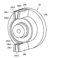
- FIG. 8 is a perspective view of the first piston member 24 in the second embodiment.
- the first wall surface member 24b and the second wall surface member 28b are not limited to the triangular plate shape described in the first embodiment.
- the first wall surface member 24b and the second wall surface member 28b may have a quadrangular plate shape as shown in FIG. 8, for example.
- the first wall surface member 24b shown in FIG. 8 has a second side 24b2 facing the housing 4, and a first side 24b1 and a third side 24b4 facing the second rotating body 28a of the second piston member 28. ing.
- the first wall surface member 24b has a corner portion 24b3 where the first side 24b1 and the second side 24b2 intersect, and a corner portion 24b5 where the first side 24b1 and the third side 24b4 intersect.
- first wall member 24b may have an arbitrary rectangular shape having a corner portion 24b3 where the first side 24b1 and the second side 24b2 intersect.
- FIG. 9 is a schematic diagram of the seal structure in the second embodiment.
- the seal structure shown in FIG. 9 has an apex seal 50 held by the first side 24b1 and in contact with the second piston member 28, and an apex held by the second side 24b2 and in contact with the housing 4.
- the seal structure further comprises a third apex seal 130.
- the apex seal 130 is held by the third side 24b4 of the first wall surface member 24b.
- An accommodation groove is formed on the third side 24b4 of the first wall member 24b, and the apex seal 130 is accommodated in the accommodation groove.
- the apex seal 130 is divided into a main piece 131 and a side piece 132.
- the main piece 131 In the axial direction (the left-right direction in FIG. 9), the main piece 131 is arranged near the second piston member 28, and the side piece 132 is arranged apart from the second piston member 28.
- the main piece 131 is arranged at the corner 24b5.
- the main piece 131 is in contact with the second piston member 28. Due to the biasing force of the spring portion, a seal generating force that presses the main piece 131 against the second piston member 28 acts, and a seal generating force that presses the side piece 132 against the main piece 131 and the first piston member 24 acts.
- the apex seal 50 shown in FIG. 9 has, in addition to the main piece 51 and the side piece 52 described in the first embodiment, a longitudinal end portion opposite to the longitudinal end portion where the side piece 52 is provided. , A side piece 55.
- the side piece 52 is in contact with the apex seal 130, and the side piece 55 is in contact with the apex seal 80.
- the seal structure of the second embodiment having such a configuration can reliably seal the gap between the first piston member 24 and the second piston member 28.
- the apex seal 50 may have the same structure as the first embodiment without the side piece 55.
- the first wall surface member 24b holds two sets of seal structures arranged in the circumferential direction.
- the first wall surface member 24b may be configured to hold one set of seal structures as in the first embodiment, or the first wall surface member 24b may be configured to hold a plurality of sets of seal structure as in the second embodiment. Good.
Landscapes
- Engineering & Computer Science (AREA)
- General Engineering & Computer Science (AREA)
- Mechanical Engineering (AREA)
- Chemical & Material Sciences (AREA)
- Combustion & Propulsion (AREA)
- Gasket Seals (AREA)
- Valve Device For Special Equipments (AREA)
Abstract
第1ピストン部材(24)の角型の第1壁面部材(24b)に、アペックスシール(50),(80)が保持されている。アペックスシール(50)は、第2ピストン部材(28)に接触して、第1ピストン部材(24)と第2ピストン部材(28)との間をシールする。アペックスシール(50)は、メインピース(51)とサイドピース(52)とを有する、長手方向に分割された構造を有している。アペックスシール(80)は、ハウジング(4)に接触して、第1ピストン部材(24)とハウジング(4)との間をシールする。アペックスシール(80)は、メインピース(81)とサイドピース(82)とを有する、長手方向に分割された構造を有している。
Description
本開示は、内燃機関のシール構造に関する。
従来、回転軸と共に回転可能に設置された第1ロータおよび第2ロータを備えるロータリエンジンにおいて、第1ロータおよび第2ロータそれぞれの基部の間の気密性を保つリング状のシール材が提案されている(たとえば、特許文献1参照)。
また従来、バンケル型ロータリエンジンのロータとハウジングとの間をアペックスシールでシールする構成が提案されている(たとえば、特許文献2および3参照)。
回転可能な2つのピストン部材で燃焼室を構成する内燃機関では、ピストン部材とハウジングとの間のシールに加えて、組み合わせた2つのピストン部材間のシールが必要となる。燃焼室の壁面を構成する部材が角部を有する形状の場合、ピストン部材間の必要シール距離が物によってばらつくため、上記各文献に記載のシール構造を適用しても対応することができず、シール性は良くない。
本開示では、燃焼室のシール性能を向上できるシール構造が提供される。
本開示に従うと、内燃機関の燃焼室内の気密を保つシール構造が提供される。内燃機関は、ハウジングと、ハウジング内に回転可能に支持される第1ピストン部材と、ハウジング内に回転可能に支持される第2ピストン部材と、を含んでいる。ハウジング、第1ピストン部材および第2ピストン部材によって、燃料を燃焼させるための燃焼室が形成される。第1ピストン部材は、環状の第1回転体と、燃焼室の周方向の壁面を構成する第1壁面部材とを有している。第2ピストン部材は、環状の第2回転体と、燃焼室の周方向の壁面を構成する第2壁面部材とを有している。第2回転体は、第1回転体に対して軸方向に隣り合って配置されている。第2回転体は、第1回転体に対向する対向面を有している。第1壁面部材は、第2ピストン部材の対向面に対向する第一辺と、ハウジングに対向する第二辺と、第一辺と第二辺とが交わる角部とを有している。シール構造は、第1アペックスシールと、第1アペックスシールとは別部材の第2アペックスシールとを有している。第1アペックスシールは、第一辺に保持されており、第2ピストン部材に接触している。第1アペックスシールは、第1メインピースと第1サイドピースとを有する長手方向に分割された構造を有している。第2アペックスシールは、第二辺に保持されており、ハウジングに接触している。第2アペックスシールは、第2メインピースと第2サイドピースとを有する長手方向に分割された構造を有している。
長手方向に分割された第1アペックスシールと、長手方向に分割された第2アペックスシールとを、それぞれ別部材として構成し、第1アペックスシールと第2アペックスシールとを組み合わせてシール構造を形成する。2つのピストン部材間の必要シール距離が物によってばらついたとしても、アペックスシールの長さが変化して追従することができ、これにより、燃焼室のシール性能を向上することができる。
上記のシール構造において、第1アペックスシールでは、第1メインピースが第1壁面部材の角部側に配置されており、第2アペックスシールでは、第2メインピースが第1壁面部材の角部側に配置されている。第1メインピースおよび第2メインピースが角部をシールする構造とすることにより、角部のシール性能を向上することができる。
上記のシール構造において、第2メインピースは、ハウジングに接触する摺動面と、摺動面の反対側の反対面とを有している。第1メインピースは、反対面に当接している。これにより、第1メインピースと第2メインピースとが角部をシールする構造を確実に実現することができる。
上記のシール構造は、第2メインピースが当接し、第2ピストン部材とハウジングとの間をシールする、第1外周シールと、第2サイドピースが当接し、第1ピストン部材とハウジングとの間をシールする、第2外周シールとを備えている。これにより、シール性をさらに向上することができる。
上記のシール構造は、燃焼室の内周部をシールする合せ面シールをさらに備えている。これにより、シール性をさらに向上することができる。
本開示に係るシール構造に従えば、燃焼室のシール性能を向上することができる。
以下、図面を参照しつつ、実施形態について説明する。以下の説明では、同一の部品には同一の符号が付されている。それらの名称および機能も同じである。したがってそれらについての詳細な説明は繰返さない。
[第1実施形態]
<エンジン2の概略構成>
図1は、実施形態の内燃機関の構成を示す斜視図である。実施形態の内燃機関は、回転ピストン型のエンジン2である。エンジン2の燃料には、たとえば、ガスやガソリンや軽油等が用いられる。エンジン2は、ハウジング4と、吸気管6と、排気管8と、インジェクタ10と、スロットルモータ14と、第1出力軸16と、第2出力軸18とを含む。
<エンジン2の概略構成>
図1は、実施形態の内燃機関の構成を示す斜視図である。実施形態の内燃機関は、回転ピストン型のエンジン2である。エンジン2の燃料には、たとえば、ガスやガソリンや軽油等が用いられる。エンジン2は、ハウジング4と、吸気管6と、排気管8と、インジェクタ10と、スロットルモータ14と、第1出力軸16と、第2出力軸18とを含む。
吸気管6の一方端は、ハウジング4の吸気ポート(図示せず)に接続される。吸気管6の他方端には、たとえば、エアクリーナ(図示せず)が接続される。エアクリーナは、エンジン2の外部から吸入される空気から異物を除去する。エンジン2の作動中において、吸気管6には、エアクリーナから吸入された空気が流通する。吸気管6を流通する空気は、ハウジング4の吸気ポートに流通する。
吸気管6には、吸気管6を流通する空気の流量を制限するスロットルバルブが設けられている。スロットルモータ14は、スロットルバルブの開度を調整する。
インジェクタ10は、吸気管6のスロットルバルブよりも上流側に設けられ、燃料(たとえば、ガス)を吸気管6内に噴射する。噴射された燃料は、吸気管6内で空気と混合されてハウジング4の吸気ポートに流通する。
ハウジング4の外周部分は、図1に示すように円筒形状によって形成されており、その内周部分も円筒形状に形成されている。ハウジング4は、その内部に、第1出力軸16に接続される第1ピストン部材と、第2出力軸18に接続される第2ピストン部材とを収納する。
排気管8の一方端は、ハウジング4の排気ポート(図示せず)に接続される。排気管8の他方端には、たとえば、排気処理装置(図示せず)が接続される。エンジン2の作動中において、ハウジング4内での燃焼により生じた排気は、ハウジング4の排気ポートから排気管8に流通する。排気管8に流通する排気は、排気処理装置によって浄化されて、エンジン2の外部に排出される。
第1出力軸16および第2出力軸18は、いずれもハウジング4内での燃料の燃焼によって回転する。第1出力軸16および第2出力軸18は、たとえば、モータジェネレータ(図示せず)の回転軸に接続される。このモータジェネレータは、たとえば、三相交流回転電機である。
<エンジン2の内部構造>
図2は、エンジン2内部に設けられるピストン部材の構成の一例を示す図である。図2を参照して、エンジン2の内部構造の一例について説明する。
図2は、エンジン2内部に設けられるピストン部材の構成の一例を示す図である。図2を参照して、エンジン2の内部構造の一例について説明する。
図2に示すように、ハウジング4内には、第1ピストン部材24と、第2ピストン部材28とが組み合わされて収納される。第1ピストン部材24は、第1回転体24aと、第1壁面部材24bとを含む。第2ピストン部材28は、第2回転体28aと、第2壁面部材28bとを含む。
第1ピストン部材24と、第2ピストン部材28とは、ハウジング4によって回転可能に支持されている。第1回転体24aと第2回転体28aとは、各々環状の形状を有している。第1回転体24aと第2回転体28aとは、図2中に一点鎖線で図示される回転中心軸AXが一致している。第1回転体24aと第2回転体28aとは、回転中心軸AXを中心に回転可能である。第1回転体24aと第2回転体28aとは、第1回転体24aの一方の端面と第2回転体28aの一方の端面とが軸方向に対向するように設けられている。第1回転体24aと第2回転体28aとは、軸方向に隣り合って配置されている。
なお本明細書中の説明では、回転中心軸AXと平行な方向を軸方向と称し、回転中心軸AXを中心とする円周に沿う方向を周方向と称し、回転中心軸AXと直交する方向を径方向と称する。径方向において、回転中心軸AXに近い側を内側と称し、回転中心軸AXから離れる側を外側と称する。
第1回転体24aは、その回転中心軸AXを含む断面に斜面部分24cを有するように形成される。第2回転体28aは、その回転中心軸AXを含む断面に斜面部分28cを有するように形成される。これにより、第1回転体24aと第2回転体28aとが組み合わされた状態において、第1回転体24aと第2回転体28aとの間には、V字形状の断面を有する凹部が周方向に形成される。第1回転体24aの斜面部分24cは、第2回転体28aに対向している。第2回転体28aの斜面部分28cは、第1回転体24aに対向している。斜面部分28cは、実施形態における対向面に相当する。
第1壁面部材24bは、第1回転体24aの斜面部分24cから、径方向外側に向けて延在し、第2回転体28aの斜面部分28cに向けて軸方向に延在するように、設けられている。第1壁面部材24bは、2つの三角形の板状部材によって構成される。第1壁面部材24bの2つの三角形の板状部材は、回転中心軸AXについて互いに対称となる位置に配置されている。
第2壁面部材28bは、第2回転体28aの斜面部分28cから、径方向外側に向けて延在し、第1回転体24aの斜面部分24cに向けて軸方向に延在するように、設けられている。第2壁面部材28bは、上述の第1壁面部材24bを構成する板状部材と同形状となる、2つの三角形の板状部材によって構成される。第2壁面部材28bの2つの三角形の板状部材は、回転中心軸AXについて互いに対称となる位置に配置されている。図2には、第2壁面部材28bの2つの板状部材のうちの一方のみが図示されている。
第1壁面部材24bおよび第2壁面部材28bの三角形の板状部材は、いずれも、第1ピストン部材24と第2ピストン部材28がハウジング4に収納されている状態において第1回転体24aと第2回転体28aとの間のV字形状の凹部とハウジング4の内周面とによって形成される三角形の断面形状に合致するように、形成される。
第1壁面部材24bは、三角形の一辺を構成する第一辺24b1と、三角形の一辺を構成する第二辺24b2と、第一辺24b1と第二辺24b2とが交わる角部24b3とを有する、角型の形状を有している。第1壁面部材24bの第一辺24b1は、第2回転体28aの斜面部分28cに対向している。第1壁面部材24bの第二辺24b2は、ハウジング4の内周面に対向している。第1壁面部材24bは、三角形の他の一辺において、第1回転体24aの斜面部分24cに固定されている。
第2壁面部材28bは、第1壁面部材24bと同様の角型の形状を有している。第2壁面部材28bの三角形の一辺は、第1回転体24aの斜面部分24cに対向している。第2壁面部材28bの三角形の一辺は、ハウジング4の内周面に対向している。第2壁面部材28bは、三角形の他の一辺において、第2回転体28aの斜面部分28cに固定されている。
第1回転体24aには、回転中心が一致するように第1出力軸16が接続される。第1回転体24aとハウジング4との間には、ワンウェイクラッチ22が設けられる。ワンウェイクラッチ22は、第1回転体24aのハウジング4内における予め定められた回転方向へのみ回転を許容し、予め定められた回転方向とは逆方向への回転を抑制する。
第2回転体28aには、回転中心が一致するように第2出力軸18が接続される。第2回転体28aとハウジング4との間には、ワンウェイクラッチ26が設けられる。ワンウェイクラッチ26は、第2回転体28aのハウジング4内における予め定められた回転方向へのみ回転を許容し、予め定められた回転方向とは逆方向への回転を抑制する。
第1壁面部材24bは、アペックスシール80を保持している。第2壁面部材28bは、アペックスシール80を保持している。第2回転体28aは、円環状の外周シール96を保持している。第1回転体24aは、円環状の外周シール97を保持している。第1回転体24aと第2回転体28aとの間に、合せ面シール40が設けられている。これらシールの詳細については後述する。
<燃焼室>
図3は、燃焼室A~Dおよびエンジン2の動作を説明するための模式図である。図3には、ハウジング4の中央部分(たとえば、第1回転体24aと第2回転体28aとの当接部分)における、回転中心軸AXに直交する断面が模式的に示される。図3に示すように、ハウジング4内には、ハウジング4、第1ピストン部材24および第2ピストン部材28によって、燃料を燃焼させるための4つの燃焼室A~Dが形成される。
図3は、燃焼室A~Dおよびエンジン2の動作を説明するための模式図である。図3には、ハウジング4の中央部分(たとえば、第1回転体24aと第2回転体28aとの当接部分)における、回転中心軸AXに直交する断面が模式的に示される。図3に示すように、ハウジング4内には、ハウジング4、第1ピストン部材24および第2ピストン部材28によって、燃料を燃焼させるための4つの燃焼室A~Dが形成される。
燃焼室A~Dは、各々、ハウジング4の内周面と、第1ピストン部材24の第1壁面部材24bおよび斜面部分24cと、第2ピストン部材28の第2壁面部材28bおよび斜面部分28cとによって、規定されている。第1壁面部材24bおよび第2壁面部材28bは、燃焼室A~Dの周方向の壁面を構成している。周方向に隣り合う2つの燃焼室は、第1壁面部材24bおよび第2壁面部材28bによって仕切られている。
図2に示されるワンウェイクラッチ22,26は、図3においては、第1ピストン部材24と第2ピストン部材28との反時計回りの回転を抑制し、時計回りの回転を許容する。
図3に示される燃焼室Aでは、圧縮された空気と燃料との混合気が自着火によって着火する膨張行程となる。すなわち、燃焼室Aで燃料が燃焼すると、第1ピストン部材24の反時計回りの移動がワンウェイクラッチ22によって抑制されるため、第1ピストン部材24の回転位置が維持されつつ、第2ピストン部材28のみが破線矢印の方向に回転し、燃焼室A内の気体の膨張とともに燃焼室Aの容積が増加する。
図3に示される燃焼室Bでは、膨張した排気が排気管8から排出される排気行程となる。すなわち、燃焼室Aでの燃料の燃焼によって、第2ピストン部材28が破線矢印の方向に回転すると、第1ピストン部材24の回転位置が維持されるため、燃焼室Bの容積が減少する。このとき、燃焼室Bは、排気管8と連通している。そのため、燃焼室B内の排気は、燃焼室Bの容積の減少とともに、排気管8に排出されていく。
図3に示される燃焼室Cでは、吸気管6から空気と燃料との混合気が吸入される吸気行程となる。すなわち、燃焼室Aでの燃料の燃焼によって、第2ピストン部材28が破線矢印の方向に回転すると、第1ピストン部材24の回転位置が維持されるため、燃焼室Cの容積が増加する。このとき、燃焼室Cは、第2ピストン部材28が破線矢印の方向に回転する途中で、吸気管6と連通する。そのため、燃焼室Cの容積の増加とともに、吸気管6から混合気が燃焼室C内に吸入される。
図3に示される燃焼室Dでは、吸気管6から吸入された混合気が圧縮される圧縮行程となる。すなわち、燃焼室Aでの燃料の燃焼によって、第2ピストン部材28が破線矢印の方向に回転すると、第1ピストン部材24の回転位置が維持されるため、燃焼室Dの容積が減少する。このとき、燃焼室Dは、吸気管6および排気管8のいずれにも連通していないため、燃焼室Dの容積の減少によって燃焼室D内の混合気が圧縮される。
そして、燃焼室D内の圧力が上昇することによって第1ピストン部材24に時計回りの力が作用すると、第1ピストン部材24が回転し、第1ピストン部材24と第2ピストン部材28との位置関係が入れ替わることとなる。
このようにして、燃焼室A~Dのうちのいずれかで燃焼する毎に、第1ピストン部材24と第2ピストン部材28とが交互に回転することによって、エンジン2が動作する。
<シール構造>
以下、燃焼室A~D内の気密を保つためのシール構造について説明する。図4は、第1ピストン部材24および第2ピストン部材28の断面図である。図4には、図2に示す回転中心軸AXを含み第1ピストン部材24の第1壁面部材24bを通る、第1ピストン部材24および第2ピストン部材28の断面が図示されている。図4においては、図中の左右方向が軸方向である。
以下、燃焼室A~D内の気密を保つためのシール構造について説明する。図4は、第1ピストン部材24および第2ピストン部材28の断面図である。図4には、図2に示す回転中心軸AXを含み第1ピストン部材24の第1壁面部材24bを通る、第1ピストン部材24および第2ピストン部材28の断面が図示されている。図4においては、図中の左右方向が軸方向である。
第1ピストン部材24と第2ピストン部材28とは、軸方向に並んで配置されている。第1ピストン部材24と第2ピストン部材28とは、軸受100を介して連結されており、互いに相対回転可能に構成されている。第1ピストン部材24には、潤滑油路241が形成されている。第2ピストン部材28には、潤滑油路281が形成されている。潤滑油路241と潤滑油路281とは連通している。
図4に示されるように、燃焼室A~Dを気密にシールするためのシール構造は、アペックスシール50,80と、合せ面シール40と、コーナーシール60と、外周シール96,97を備えている。
アペックスシール50は、第1ピストン部材24の第1壁面部材24bに保持されている。第1壁面部材24bには収容溝245が形成されており、収容溝245内にアペックスシール50が収容されている。収容溝245は、第1壁面部材24bの、第2ピストン部材28の斜面部分28cに対向する縁、すなわち図2に示される第1壁面部材24bの第一辺24b1に、形成されている。アペックスシール50は、第1壁面部材24bの第一辺24b1に保持されている。アペックスシール50は、実施形態における第1アペックスシールに相当する。
アペックスシール80は、アペックスシール50とは別部材として設けられている。アペックスシール80は、第1ピストン部材24の第1壁面部材24bに保持されている。第1壁面部材24bには収容溝248が形成されており、収容溝248内にアペックスシール80が収容されている。収容溝248は、第1壁面部材24bの、ハウジング4の内周面に対向する外周縁、すなわち図2に示される第1壁面部材24bの第二辺24b2に、形成されている。アペックスシール80は、第1壁面部材24bの第二辺24b2に保持されている。アペックスシール80は、実施形態における第2アペックスシールに相当する。
合せ面シール40は、図2に示されるように、環状の形状を有している。合せ面シール40は、図4に示されるように、第2ピストン部材28の斜面部分28cよりも径方向の内側に配置されている。合せ面シール40は、第1壁面部材24bよりも径方向の内側に配置されている。したがって合せ面シール40は、燃焼室A~Dよりも径方向の内側に配置されており、燃焼室A~Dの内周部をシールしている。合せ面シール40は、燃焼室A~Dから内周側へのガスの漏れを抑制している。
合せ面シール40は、第1ピストン部材24に保持されている。第1ピストン部材24には環状溝が形成されており、この環状溝内に合せ面シール40が収容されている。合せ面シール40は、第2ピストン部材28に密着している。第1ピストン部材24と第2ピストン部材28との相対回転に伴い、合せ面シール40は第2ピストン部材28に対して摺動する。
コーナーシール60は、合せ面シール40とアペックスシール50との交差部に配置されている。第1ピストン部材24には、第1壁面部材24bの径方向内側の端部に収容凹部が形成されており、この収容凹部内にコーナーシール60が収容されている。したがってコーナーシール60は、第1壁面部材24bの径方向内側の端部において、第1ピストン部材24に保持されている。収容凹部の底面にはばね部材73が設けられており、ばね部材73はコーナーシール60を収容凹部の外側へ向けて付勢している。
コーナーシール60は、シール面61を有している。シール面61は、第2ピストン部材28に接触している。第1ピストン部材24と第2ピストン部材28との相対回転に伴い、シール面61は第2ピストン部材28に対して摺動する。ばね部材73がコーナーシール60を付勢していることにより、シール面61の第2ピストン部材28への密着性が確保されている。
コーナーシール60には、シール面61の一部分が窪んだ凹部が形成されている。この凹部内に合せ面シール40の一部が配置されて、合せ面シール40はコーナーシール60と係合している。コーナーシール60の径方向外側の表面に、スリット状の差込部が形成されている。この差込部にアペックスシール50が差し込まれて、アペックスシール50はコーナーシール60と係合している。コーナーシール60は、アペックスシール50と合せ面シール40とを接続して、シールの切れ目を発生させないようにしている。
図5は、シール構造を拡大して示す断面図である。図5に示されるように、アペックスシール50は、その長手方向端部において、当該長手方向に対して傾斜する傾斜面によって、メインピース51とサイドピース52とに分割されている。アペックスシール50は、メインピース51とサイドピース52とを有する、長手方向に分割された構造を有している。メインピース51は、実施形態における第1メインピースに相当する。サイドピース52は、実施形態における第1サイドピースに相当する。
アペックスシール50の長手方向におけるサイドピース52の長さは、メインピース51の長さに比べてかなり短い。径方向(図5においては図中の上下方向)において、メインピース51が外側に配置され、サイドピース52が内側に配置されている。第1壁面部材24bの角部24b3には、サイドピース52ではなく、メインピース51が配置されている。
メインピース51とサイドピース52とに対して収容溝245の底側に、弓型形状のスプリング部53,54が設置されている。スプリング部53,54は、メインピース51とサイドピース52とを、収容溝245の外側へ向けて、すなわち第2ピストン部材28へ向けて付勢している。これによりメインピース51とサイドピース52とは、第2ピストン部材28、より具体的には第2回転体28aの斜面部分28cに接触している。スプリング部53,54はまた、メインピース51とサイドピース52とを、その長手方向の両端に向けて付勢している。
アペックスシール80は、その長手方向端部において、当該長手方向に対して傾斜する傾斜面によって、メインピース81とサイドピース82とに分割されている。アペックスシール80は、メインピース81とサイドピース82とを有する、長手方向に分割された構造を有している。メインピース81は、実施形態における第2メインピースに相当する。サイドピース82は、実施形態における第2サイドピースに相当する。
アペックスシール80の長手方向におけるサイドピース82の長さは、メインピース81の長さに比べてかなり短い。軸方向(図5においては図中の左右方向)において、メインピース81が第2ピストン部材28に近く配置され、サイドピース82が第2ピストン部材28から離れて配置されている。第1壁面部材24bの角部24b3には、サイドピース82ではなく、メインピース81が配置されている。
メインピース81とサイドピース82とに対して収容溝248の底側に、弓型形状のスプリング部83,84が設置されている。スプリング部83,84は、メインピース81とサイドピース82とを、収容溝248の外側へ向けて、すなわちハウジング4へ向けて付勢している。これによりメインピース81とサイドピース82とは、ハウジング4の内周面に接触している。スプリング部83,84はまた、メインピース81とサイドピース82とを、その長手方向の両端に向けて付勢している。
メインピース81は、ハウジング4に接触する摺動面81s1と、摺動面81s1の反対側の反対面81s2とを有している。メインピース51の、サイドピース52に対向しない側の端部が、メインピース81の反対面81s2に当接している。これにより、第1壁面部材24bの角部24b3が、メインピース51およびメインピース81によってシールされることになる。
アペックスシールのメインピースとサイドピースとの配置の向きは、必ずしも上記内容に限定されない。たとえば、アペックスシール50とアペックスシール80との合わせ部側、すなわち第1壁面部材24bの角部24b3側に、サイドピースを配置しても良い。
外周シール96は、図2に示されるように、環状の形状を有している。図4,5に示されるように、外周シール96は、第2ピストン部材28に保持されている。メインピース81の、サイドピース82に対向しない側の端部が、外周シール96に当接している。外周シール96は、アペックスシール80に接触し、第2ピストン部材28に接触し、かつ、ハウジング4の内周面に接触している。外周シール96は、第2ピストン部材28とハウジング4との間をシールしている。外周シール96は、実施形態の第1外周シールに相当する。
外周シール97は、図2に示されるように、環状の形状を有している。図4,5に示されるように、外周シール97は、第1ピストン部材24に保持されている。サイドピース82が、外周シール97に当接している。外周シール97は、アペックスシール80に接触し、第1ピストン部材24に接触し、かつ、ハウジング4の内周面に接触している。外周シール97は、第1ピストン部材24とハウジング4との間をシールしている。外周シール97は、実施形態の第2外周シールに相当する。
図6は、第1ピストン部材24とハウジング4との間のシール発生力を示す模式図である。上述した通り、スプリング部83,84がメインピース81およびサイドピース52に付勢力を作用する。スプリング部84の付勢力によって、メインピース81にシール発生力F1が作用する。シール発生力F1は、外周シール96を第2ピストン部材28に押し付けるように作用する。このようにして、第2ピストン部材28とハウジング4との間の隙間が、外周シール96によって確実にシールされる。
スプリング部83,84の付勢力によって、メインピース81にシール発生力F2が作用する。シール発生力F2は、メインピース81をハウジング4に押し付けるように作用する。スプリング部84の付勢力によって、サイドピース82にシール発生力F3,F4が作用する。シール発生力F3は、サイドピース82をメインピース81に押し付けるように作用する。シール発生力F4は、外周シール97を第1ピストン部材24に押し付けるように作用する。このようにして、第1ピストン部材24とハウジング4との間の隙間が、アペックスシール80および外周シール97によって確実にシールされる。
図7は、第1ピストン部材24および第2ピストン部材28の間のシール発生力を示す模式図である。上述した通り、スプリング部53,54がメインピース51およびサイドピース52に付勢力を作用する。スプリング部53,54の付勢力によって、メインピース51にシール発生力F5,F6が作用する。シール発生力F5は、メインピース51をメインピース81の反対面81s2に押し付けるように作用する。シール発生力F6は、メインピース51を第2ピストン部材28に押し付けるように作用する。
スプリング部54の付勢力によって、サイドピース52にシール発生力F7,F8が作用する。シール発生力F7は、サイドピース52をメインピース51に押し付けるように作用する。シール発生力F8は、サイドピース52をコーナーシール60に押し付けるように作用する。このようにして、第1ピストン部材24と第2ピストン部材28との間の隙間が、アペックスシール50によって確実にシールされる。
<作用および効果>
以上説明した実施形態のシール構造では、図5に示されるように、第1ピストン部材24の角型の第1壁面部材24bに、アペックスシール50,80が保持されている。アペックスシール50は、第2ピストン部材28に接触して、第1ピストン部材24と第2ピストン部材28との間をシールする。アペックスシール80は、ハウジング4に接触して、第1ピストン部材24とハウジング4との間をシールする。アペックスシール50とアペックスシール80とは、別部材として構成されており、各々が長手方向に分割されている。このようなアペックスシール50とアペックスシール80とを組み合わせてシール構造を形成することで、ハウジング4、第1ピストン部材24、および第2ピストン部材28の寸法ばらつきおよび相対動きにより発生する隙間を吸収できるので、燃焼室A~Dのシール性能を向上することができる。
以上説明した実施形態のシール構造では、図5に示されるように、第1ピストン部材24の角型の第1壁面部材24bに、アペックスシール50,80が保持されている。アペックスシール50は、第2ピストン部材28に接触して、第1ピストン部材24と第2ピストン部材28との間をシールする。アペックスシール80は、ハウジング4に接触して、第1ピストン部材24とハウジング4との間をシールする。アペックスシール50とアペックスシール80とは、別部材として構成されており、各々が長手方向に分割されている。このようなアペックスシール50とアペックスシール80とを組み合わせてシール構造を形成することで、ハウジング4、第1ピストン部材24、および第2ピストン部材28の寸法ばらつきおよび相対動きにより発生する隙間を吸収できるので、燃焼室A~Dのシール性能を向上することができる。
実施形態のシール構造によって燃焼室A~Dが気密にシールされるので、燃焼室A~Dからの気体の漏れを低減できる。したがって、エンジン2の燃焼効率および排気性能の向上が可能であり、エンジン2の性能向上を達成することができる。
図5に示されるように、第1壁面部材24bの角部24b3を、アペックスシール50のメインピース51とアペックスシール80のメインピース81とがシールしている。このようにすれば、角部24b3のシール性能を向上することができる。また、アペックスシール80のスプリング部84の形状の設計を容易にできる。
図5に示されるように、アペックスシール50のメインピース51が、アペックスシール80のメインピース81の反対面81s2に当接している。これにより、メインピース51およびメインピース81が角部24b3をシールする構造を確実に実現することができる。
図5に示されるように、ピストン部材とハウジング4との間をシールする外周シール96,97が設けられている。これにより、シール性をさらに向上することができる。
図4に示されるように、燃焼室A~Dの内周部をシールする合せ面シール40が設けられている。これにより、シール性をさらに向上することができる。
[第2実施形態]
図8は、第2実施形態における第1ピストン部材24の斜視図である。第1壁面部材24bおよび第2壁面部材28bは、第一実施形態で説明した三角形の板状形状に限られない。第1壁面部材24bおよび第2壁面部材28bは、たとえば図8に示されるように、四角形の板状形状を有してもよい。図8に示される第1壁面部材24bは、ハウジング4に対向する第二辺24b2と、第2ピストン部材28の第2回転体28aに対向する第一辺24b1および第三辺24b4とを有している。第1壁面部材24bは、第一辺24b1と第二辺24b2とが交わる角部24b3と、第一辺24b1と第三辺24b4とが交わる角部24b5とを有している。
図8は、第2実施形態における第1ピストン部材24の斜視図である。第1壁面部材24bおよび第2壁面部材28bは、第一実施形態で説明した三角形の板状形状に限られない。第1壁面部材24bおよび第2壁面部材28bは、たとえば図8に示されるように、四角形の板状形状を有してもよい。図8に示される第1壁面部材24bは、ハウジング4に対向する第二辺24b2と、第2ピストン部材28の第2回転体28aに対向する第一辺24b1および第三辺24b4とを有している。第1壁面部材24bは、第一辺24b1と第二辺24b2とが交わる角部24b3と、第一辺24b1と第三辺24b4とが交わる角部24b5とを有している。
代替的には、第1壁面部材24bは、第一辺24b1と第二辺24b2とが交わる角部24b3を有する、任意の角型の形状を有してもよい。
図9は、第2実施形態におけるシール構造の模式図である。なお図9では、各アペックスシールのスプリング部は図示を省略されている。図9に示されるシール構造は、第1実施形態と同様に、第一辺24b1に保持され第2ピストン部材28に接触するアペックスシール50と、第二辺24b2に保持されハウジング4に接触するアペックスシール80とを備えている。シール構造はさらに、第3のアペックスシール130を備えている。アペックスシール130は、第1壁面部材24bの第三辺24b4に保持されている。第1壁面部材24bの第三辺24b4には収容溝が形成されており、この収容溝内にアペックスシール130が収容されている。
アペックスシール130は、メインピース131とサイドピース132とに分割されている。軸方向(図9においては図中の左右方向)において、メインピース131が第2ピストン部材28に近く配置され、サイドピース132が第2ピストン部材28から離れて配置されている。角部24b5には、メインピース131が配置されている。メインピース131は、第2ピストン部材28に接触している。スプリング部の付勢力によって、メインピース131を第2ピストン部材28に押し付けるシール発生力が作用し、サイドピース132をメインピース131および第1ピストン部材24に押し付けるシール発生力が作用する。
図9に示されるアペックスシール50は、第1実施形態で説明したメインピース51およびサイドピース52に加えて、サイドピース52が設けられている長手方向端部とは逆側の長手方向端部に、サイドピース55を備えている。サイドピース52はアペックスシール130に当接し、サイドピース55はアペックスシール80に当接している。
このような構成を備えている第2実施形態のシール構造によって、第1ピストン部材24と第2ピストン部材28との間の隙間を確実にシールすることができる。なおアペックスシール50は、サイドピース55を有しない第1実施形態と同じ構造であっても構わない。
第2実施形態では、第1壁面部材24bは、周方向に並ぶ2組のシール構造を保持している。第1実施形態のように第1壁面部材24bが1組のシール構造を保持する構成としてもよく、第2実施形態のように第1壁面部材24bが複数組のシール構造を保持する構成としてもよい。
以上のように実施形態について説明を行なったが、今回開示された実施形態はすべての点で例示であって制限的なものではないと考えられるべきである。本発明の範囲は上記した説明ではなくて特許請求の範囲によって示され、特許請求の範囲と均等の意味および範囲内でのすべての変更が含まれることが意図される。
2 エンジン
4 ハウジング
24 第1ピストン部材
24a 第1回転体
24b 第1壁面部材
24b1 第一辺
24b2 第二辺
24b3,24b5 角部
24b4 第三辺
24c,28c 斜面部分
28 第2ピストン部材
28a 第2回転体
28b 第2壁面部材
40 合せ面シール
50,80,130 アペックスシール
51,81,131 メインピース
52,55,82,132 サイドピース
53,54,83,84 スプリング部
60 コーナーシール
61 シール面
73 ばね部材
81s1 摺動面
81s2 反対面
96,97 外周シール
245,248 収容溝
A,B,C,D 燃焼室
AX 回転中心軸
F1~F8 シール発生力
4 ハウジング
24 第1ピストン部材
24a 第1回転体
24b 第1壁面部材
24b1 第一辺
24b2 第二辺
24b3,24b5 角部
24b4 第三辺
24c,28c 斜面部分
28 第2ピストン部材
28a 第2回転体
28b 第2壁面部材
40 合せ面シール
50,80,130 アペックスシール
51,81,131 メインピース
52,55,82,132 サイドピース
53,54,83,84 スプリング部
60 コーナーシール
61 シール面
73 ばね部材
81s1 摺動面
81s2 反対面
96,97 外周シール
245,248 収容溝
A,B,C,D 燃焼室
AX 回転中心軸
F1~F8 シール発生力
Claims (5)
- ハウジングと、前記ハウジング内に回転可能に支持される第1ピストン部材と、前記ハウジング内に回転可能に支持される第2ピストン部材と、を含み、前記ハウジング、前記第1ピストン部材および前記第2ピストン部材によって燃料を燃焼させるための燃焼室が形成される、内燃機関において、前記燃焼室内の気密を保つシール構造であって、
前記第1ピストン部材は、環状の第1回転体と、前記燃焼室の周方向の壁面を構成する第1壁面部材とを有し、
前記第2ピストン部材は、前記第1回転体に対して軸方向に隣り合って配置された環状の第2回転体と、前記燃焼室の周方向の壁面を構成する第2壁面部材とを有し、前記第2回転体は前記第1回転体に対向する対向面を有し、
前記第1壁面部材は、前記第2ピストン部材の前記対向面に対向する第一辺と、前記ハウジングに対向する第二辺と、前記第一辺と前記第二辺とが交わる角部とを有し、
前記シール構造は、
前記第一辺に保持され、前記第2ピストン部材に接触する、第1メインピースと第1サイドピースとを有する長手方向に分割された、第1アペックスシールと、
前記第二辺に保持され、前記ハウジングに接触する、第2メインピースと第2サイドピースとを有する長手方向に分割された、前記第1アペックスシールとは別部材の第2アペックスシールとを有する、内燃機関のシール構造。 - 前記第1メインピースおよび前記第2メインピースが前記角部側に配置されている、請求項1に記載のシール構造。
- 前記第2メインピースは、前記ハウジングに接触する摺動面と、前記摺動面の反対側の反対面とを有し、
前記第1メインピースは、前記反対面に当接する、請求項2に記載のシール構造。 - 前記第2メインピースが当接し、前記第2ピストン部材と前記ハウジングとの間をシールする、第1外周シールと、
前記第2サイドピースが当接し、前記第1ピストン部材と前記ハウジングとの間をシールする、第2外周シールとを備える、請求項2または3に記載のシール構造。 - 前記燃焼室の内周部をシールする合せ面シールをさらに備える、請求項1~4のいずれか1項に記載のシール構造。
Applications Claiming Priority (2)
| Application Number | Priority Date | Filing Date | Title |
|---|---|---|---|
| JP2018230119A JP7047736B2 (ja) | 2018-12-07 | 2018-12-07 | 内燃機関のシール構造 |
| JP2018-230119 | 2018-12-07 |
Publications (1)
| Publication Number | Publication Date |
|---|---|
| WO2020116191A1 true WO2020116191A1 (ja) | 2020-06-11 |
Family
ID=70975446
Family Applications (1)
| Application Number | Title | Priority Date | Filing Date |
|---|---|---|---|
| PCT/JP2019/045738 Ceased WO2020116191A1 (ja) | 2018-12-07 | 2019-11-22 | 内燃機関のシール構造 |
Country Status (2)
| Country | Link |
|---|---|
| JP (1) | JP7047736B2 (ja) |
| WO (1) | WO2020116191A1 (ja) |
Citations (3)
| Publication number | Priority date | Publication date | Assignee | Title |
|---|---|---|---|---|
| US5406916A (en) * | 1990-04-07 | 1995-04-18 | Rodrigues; Michael V. | Double acting, rectangular faced, arc shaped, oscillating piston quadratic internal combustion engine or machine |
| WO2007132069A1 (fr) * | 2006-05-12 | 2007-11-22 | Mrcc Industries Sas | Segments d'etancheite pour des machines a pistons rotatifs |
| JP2014055583A (ja) * | 2012-09-11 | 2014-03-27 | Takeshi Hatanaka | ロータリ燃焼機関、ハイブリッドロータリ燃焼機関及びこれらを具備した機械装置 |
Family Cites Families (2)
| Publication number | Priority date | Publication date | Assignee | Title |
|---|---|---|---|---|
| GB1187052A (en) | 1967-01-26 | 1970-04-08 | Charles John Francis | Improvements in or relating to Rotary-Piston Internal Combustion Engines. |
| JPS4718163Y1 (ja) * | 1969-02-17 | 1972-06-23 |
-
2018
- 2018-12-07 JP JP2018230119A patent/JP7047736B2/ja active Active
-
2019
- 2019-11-22 WO PCT/JP2019/045738 patent/WO2020116191A1/ja not_active Ceased
Patent Citations (3)
| Publication number | Priority date | Publication date | Assignee | Title |
|---|---|---|---|---|
| US5406916A (en) * | 1990-04-07 | 1995-04-18 | Rodrigues; Michael V. | Double acting, rectangular faced, arc shaped, oscillating piston quadratic internal combustion engine or machine |
| WO2007132069A1 (fr) * | 2006-05-12 | 2007-11-22 | Mrcc Industries Sas | Segments d'etancheite pour des machines a pistons rotatifs |
| JP2014055583A (ja) * | 2012-09-11 | 2014-03-27 | Takeshi Hatanaka | ロータリ燃焼機関、ハイブリッドロータリ燃焼機関及びこれらを具備した機械装置 |
Also Published As
| Publication number | Publication date |
|---|---|
| JP2020090951A (ja) | 2020-06-11 |
| JP7047736B2 (ja) | 2022-04-05 |
Similar Documents
| Publication | Publication Date | Title |
|---|---|---|
| JPH0693872A (ja) | 複合回転羽根エンジン | |
| CN107110031A (zh) | 阀装置 | |
| CA2782745C (en) | Apex seal arrangement for rotary internal combustion engine | |
| JP7047736B2 (ja) | 内燃機関のシール構造 | |
| WO2021039531A1 (ja) | 圧縮機、ガスタービン | |
| US9850758B2 (en) | Apex and face seals with rotary internal combustion engine | |
| JP7188290B2 (ja) | シール構造 | |
| CA2782794C (en) | Apex seal for rotary internal combustion engine | |
| JP7143821B2 (ja) | シール構造 | |
| JP6950649B2 (ja) | 内燃機関のシール構造 | |
| JP5563370B2 (ja) | ロータリーピストンエンジンのためのロータリーピストン、及びロータリーピストンエンジン | |
| JP7200794B2 (ja) | 内燃機関のシール構造 | |
| JP7078907B2 (ja) | 内燃機関のシール構造 | |
| US20130028773A1 (en) | Apex seal for rotary internal combustion engine | |
| JP2021050720A (ja) | 内燃機関 | |
| JP6107800B2 (ja) | ロータリーピストンエンジンのアペックスシール構造 | |
| KR20190076386A (ko) | 기밀 유지가 향상된 회전용 동력 기관 및 이에 포함되는 기밀 유지 장치 | |
| JP2016109061A (ja) | ロータリーピストンエンジンのアペックスシール構造 | |
| CA2782732C (en) | Gas seal arrangement for rotary internal combustion engine | |
| US20250264023A1 (en) | Internal combustion engine | |
| RU2272164C2 (ru) | Роторный двигатель внутреннего сгорания | |
| KR20220100438A (ko) | 로터리 엔진 | |
| KR20220103447A (ko) | 로터리 엔진 | |
| US8905736B2 (en) | Port for rotary internal combustion engine | |
| WO2017051484A1 (ja) | 火花点火内燃機関 |
Legal Events
| Date | Code | Title | Description |
|---|---|---|---|
| 121 | Ep: the epo has been informed by wipo that ep was designated in this application |
Ref document number: 19893054 Country of ref document: EP Kind code of ref document: A1 |
|
| NENP | Non-entry into the national phase |
Ref country code: DE |
|
| 122 | Ep: pct application non-entry in european phase |
Ref document number: 19893054 Country of ref document: EP Kind code of ref document: A1 |