WO2020116079A1 - 回転操作装置 - Google Patents
回転操作装置 Download PDFInfo
- Publication number
- WO2020116079A1 WO2020116079A1 PCT/JP2019/043504 JP2019043504W WO2020116079A1 WO 2020116079 A1 WO2020116079 A1 WO 2020116079A1 JP 2019043504 W JP2019043504 W JP 2019043504W WO 2020116079 A1 WO2020116079 A1 WO 2020116079A1
- Authority
- WO
- WIPO (PCT)
- Prior art keywords
- rotation
- stopper
- rotating member
- operation knob
- rotary
- Prior art date
- Legal status (The legal status is an assumption and is not a legal conclusion. Google has not performed a legal analysis and makes no representation as to the accuracy of the status listed.)
- Ceased
Links
Images


Classifications
-
- G—PHYSICS
- G05—CONTROLLING; REGULATING
- G05G—CONTROL DEVICES OR SYSTEMS INSOFAR AS CHARACTERISED BY MECHANICAL FEATURES ONLY
- G05G1/00—Controlling members, e.g. knobs or handles; Assemblies or arrangements thereof; Indicating position of controlling members
- G05G1/08—Controlling members for hand actuation by rotary movement, e.g. hand wheels
-
- G—PHYSICS
- G05—CONTROLLING; REGULATING
- G05G—CONTROL DEVICES OR SYSTEMS INSOFAR AS CHARACTERISED BY MECHANICAL FEATURES ONLY
- G05G5/00—Means for preventing, limiting or returning the movements of parts of a control mechanism, e.g. locking controlling member
-
- G—PHYSICS
- G05—CONTROLLING; REGULATING
- G05G—CONTROL DEVICES OR SYSTEMS INSOFAR AS CHARACTERISED BY MECHANICAL FEATURES ONLY
- G05G5/00—Means for preventing, limiting or returning the movements of parts of a control mechanism, e.g. locking controlling member
- G05G5/03—Means for enhancing the operator's awareness of arrival of the controlling member at a command or datum position; Providing feel, e.g. means for creating a counterforce
-
- B—PERFORMING OPERATIONS; TRANSPORTING
- B60—VEHICLES IN GENERAL
- B60K—ARRANGEMENT OR MOUNTING OF PROPULSION UNITS OR OF TRANSMISSIONS IN VEHICLES; ARRANGEMENT OR MOUNTING OF PLURAL DIVERSE PRIME-MOVERS IN VEHICLES; AUXILIARY DRIVES FOR VEHICLES; INSTRUMENTATION OR DASHBOARDS FOR VEHICLES; ARRANGEMENTS IN CONNECTION WITH COOLING, AIR INTAKE, GAS EXHAUST OR FUEL SUPPLY OF PROPULSION UNITS IN VEHICLES
- B60K20/00—Arrangement or mounting of change-speed gearing control devices in vehicles
- B60K20/02—Arrangement or mounting of change-speed gearing control devices in vehicles of initiating means
Definitions
- the present invention relates to a rotary operation device.
- a rotation operation device capable of electrically controlling a shift change of a transmission by a rotation operation using an operation knob is known.
- a rotary operation device when a predetermined condition is satisfied (for example, when the current shift position is at the left or right shift position in the shift pattern), the operation knob is rotated by driving the motor. Techniques have been devised that can be restricted.
- Patent Document 1 relates to an operating device capable of controlling a rotation angle of a rotary knob by bringing an abutment cam provided on a rotary knob capable of rotating operation into contact with a stopper device.
- a technique is disclosed in which the contact position between the contact cam and the stopper device can be changed by rotating the stopper device by driving.
- Patent Document 2 a shift capable of controlling the displacement of a knob by bringing a protrusion provided on a rotatable knob into contact with a first engaging portion and a second engaging portion.
- the apparatus there is a technique capable of changing the contact position between the protrusion and the first engaging portion and the second engaging portion by rotating the first cam and the second cam by driving the motor. It is disclosed.
- a rotary operation device includes an operation knob that is rotationally operated, a rotation system of the operation knob that is provided integrally with or separately from the operation knob that rotates together with the rotation operation of the operation knob, and an operation feeling for the rotation operation. And a plurality of stoppers arranged so as to be movable between the outside and the inside of the circumferential movement path of the rotation system of the operation knob.
- the rotating member has a pressing portion provided so as to project toward the stopper, and when the pressing portion moves in accordance with the rotational driving of the rotating member, the pressing portion corresponds to the pressing portion of the plurality of stoppers. Only the stopper at the position is moved from the outside to the inside of the circumferential movement path of the rotation system of the operation knob, and the stopper is engaged with the rotation system of the operation knob.
- FIG. 1 is an external perspective view of a rotary operation device according to an embodiment.
- the top view of the rotation operating device which concerns on one Embodiment Side view of the rotary operation device according to one embodiment 1 is an exploded perspective view of a rotary operation device according to an embodiment.
- the Z-axis direction in the drawing is the vertical direction (the height direction of the case 120), and the X-axis direction in the drawing is the front-back direction (the short side direction of the case 120).
- the axial direction is the left-right direction (longitudinal direction of the case 120).
- FIG. 1 is an external perspective view of a rotary operation device 100 according to an embodiment.
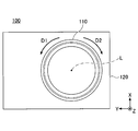
- FIG. 2 is a plan view of the rotary operation device 100 according to the embodiment.
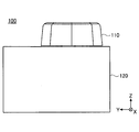
- FIG. 3 is a side view of the rotation operation device 100 according to the embodiment.
- a rotary operation device 100 shown in FIGS. 1 to 3 is a rotary operation device installed in the vicinity of a driver's seat in a vehicle such as an automobile, and electrically changes a shift of a transmission mounted on the vehicle. It is a rotary operation device for controlling.
- the rotation operating device 100 does not mechanically control the transmission, but employs a so-called shift-by-wire system in which a transmission is electrically controlled by outputting a control signal according to a shift operation to the outside. ..
- the rotary operation device 100 may be used for purposes other than shift change of the transmission, and may be used for devices other than vehicles (for example, aircraft, railway vehicles, game machines, remote controllers, etc.). Further, the rotary operation device 100 actually has an electrical configuration for outputting an electrical signal according to a shift operation, but in the present embodiment, illustration and description of this electrical configuration are given. Will be omitted.
- the rotary operation device 100 has an overall shape in which a cylindrical operation knob 110 is projected from the upper surface of a case 120 having a rectangular parallelepiped shape. Further, the rotation operation device 100 has a counterclockwise direction (direction of arrow D1 shown in FIG. 2) and a clockwise direction (direction of arrow D2 shown in FIG. 2) in a plan view from above (the positive direction of the Z axis in the drawing). The operation knob 110 can be rotated in each direction.
- the rotary operation device 100 can switch the shift position of the transmission to any of a plurality of shift positions (for example, P, R, N, D, S, etc.) by rotating the operation knob 110.
- a plurality of shift positions for example, P, R, N, D, S, etc.
- the rotation operation device 100 is provided with an operation feeling imparting mechanism 130. Thereby, the rotation operation device 100 can switch the shift position of the transmission every time a rotation operation of a predetermined angle is performed, while giving an operation feeling (a so-called click feeling) to the rotation operation. is there. That is, the rotation operation device 100 can make the operator of the rotation operation tactilely know that the switching of the shift position has been reliably performed. Further, the rotation operating device 100 can display to the operator which shift position the shift operating position is by a display device of the operation knob 110 (not shown).
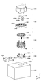
- FIG. 4 is an exploded perspective view of the rotary operation device 100 according to the embodiment.
- the rotation operation device 100 is configured to include an operation knob 110, an operation feeling imparting mechanism 130, a stopper mechanism 140, a drive mechanism 150, and a case 120 in order from the upper side in the drawing.
- the operation knob 110 is a columnar member that protrudes from the upper surface of the case 120 and is rotatably provided around a rotation axis L set along the Z axis.
- the operation knob 110 is rotated counterclockwise or clockwise in a plan view from above (Z axis positive direction in the figure) when a rotation operation is performed by the operator.
- the operation feeling imparting mechanism 130 is a mechanism for imparting an operation feeling to the rotating operation of the operation knob 110.
- the operation feeling imparting mechanism 130 has a plunger 132 and a feeling cam 134.
- the feeling cam 134 is an annular member arranged coaxially with the rotation axis L of the operation knob 110.
- a plurality of cam ridges 134A protruding toward the rotation axis L are continuously provided along the inner peripheral surface.
- a valley portion 134B is formed between two adjacent cam ridges 134A.
- the feeling cam 134 is fixed inside the case 120 by an arbitrary fixing means (not shown) so as not to rotate.
- the plunger 132 is provided inside the feeling cam 134.
- the plunger 132 is a columnar member extending in the horizontal direction (direction orthogonal to the rotation axis L direction (Z axis direction)).
- the plunger 132 is connected to the bottom portion 110A of the operation knob 110 and rotates together with the operation knob 110.
- protrusions 132A On both end surfaces of the plunger 132, protrusions 132A that protrude outward in the radial direction are provided.
- the protrusion 132A is expandable/contractible in the longitudinal direction of the plunger 132, and is biased toward the outer side in the longitudinal direction of the plunger 132 by a coil spring (not shown) provided inside the plunger 132.
- the protrusion 132A has a protrusion shape that fits in a valley 134B formed on the inner peripheral surface of the feeling cam 134.
- the projection 132A moves along the inner peripheral surface of the feeling cam 134 while repeatedly expanding and contracting as the operation knob 110 rotates.
- the projection 132A is gradually pressed in the direction of the rotation center axis by the cam crest 134A from the valley 134B to the top of the cam crest 134A.
- the load related to the rotation operation of the operation knob 110 gradually increases.
- the protrusion 132A exceeds the top of the cam crest 134A, the protrusion 132A extends outward due to the elastic return force of the coil spring that biases the protrusion 132A.
- the protrusion 132A slides into the valley 134B while urging the rotation of the operation knob 110. At this time, the load related to the rotation operation of the operation knob 110 is rapidly reduced. Then, when the protrusion 132A reaches the bottom of the valley 134B, the rotation of the operation knob 110 is suddenly stopped.
- the operation feeling imparting mechanism 130 changes the load related to the rotation operation of the operation knob 110 in this manner, thereby giving an operation feeling (so-called click feeling) to the rotation operation of the operation knob 110, and When the rotation operation is completed, the operation knob 110 is held at a predetermined position at the position of the valley portion 134B.
- both ends of the bottom surface of the plunger 132 are provided with restricting portions 132B (an example of a rotating system of the operation knob) protruding outward in the longitudinal direction of the plunger 132.
- the restriction portion 132B restricts the rotation of the plunger 132 by the stopper 146 pushed upward by the pressing portion 152A of the rotating member 152 coming into contact with the side surface of the restriction portion 132B. Since the plunger 132 is connected to the operation knob 110, when the rotation of the plunger 132 is restricted, the rotation of the operation knob 110 is also restricted.
- the stopper mechanism 140 has a stopper holder 142, a plurality of stoppers 146, and a coil spring 144.
- the stopper holder 142 is an annular member that is arranged coaxially with the rotation axis L together with the operation knob 110, the feeling cam 134, and the rotation member 152.
- the stopper holder 142 is provided with a plurality of through holes 142 ⁇ /b>A penetrating the stopper holder 142 in the vertical direction side by side along the circumferential direction.
- the stopper holder 142 supports the upper portions of the plurality of stoppers 146 slidably in the vertical direction by the upper portions of the stoppers 146 penetrating through the respective through holes 142A.
- the stopper 146 is a rod-shaped member that is provided so as to be vertically slidable in the through hole 142A formed in the stopper holder 142.
- the pressing portion 152A of the rotating member 152 moves to the position corresponding to the stopper, one end of the stopper 146 is pushed upward by the pressing portion 152A and the other end of the restriction portion 132B of the plunger 132. Penetrate inside the circumferential movement path.
- the stopper 146 engages with the restricting portion 132B of the plunger 132 that has been rotationally operated, interrupts the movement path in the circumferential direction, and thus limits the rotational operation of the operation knob 110.
- the rotary operation device 100 of the present embodiment includes a plurality of stoppers 146 arranged in a ring shape along the circumferential direction of the rotary member 152.
- the rotary operation device 100 of the present embodiment is provided with a coil spring 144 for each stopper 146.
- the coil spring 144 is sandwiched between the lower surface of the stopper holder 142 and the support portion of the stopper 146 extending in the lateral direction, and urges the stopper 146 downward.
- the stopper 146 is pushed upward, the coil spring 144 is compressed between the lower surface of the stopper holder 142 and the support portion of the stopper 146.
- the coil spring 144 pushes the stopper 146 downward due to the elastic return force, which causes the stopper 146 to move to the outside of the circumferential movement path of the restriction portion 132B of the plunger 132. evacuate.
- the drive mechanism 150 includes a rotating member 152, a gear 154, and a motor 156.
- the rotating member 152 is an annular member that is arranged coaxially with the stopper holder 142 with respect to the rotation axis L and has the same radius as the stopper holder 142.
- the rotating member 152 has an external gear 152B formed over the entire outer peripheral surface of the rotating member 152.
- the external gear 152B meshes with the gear 154, and receives the rotational force from the motor 156 via the gear 154 to rotate the rotating member 152.
- the upper end surface of the rotating member 152 supports the lower end portions of the stoppers 146 by abutting the lower end portions of the stoppers 146.
- the upper end surface of the rotating member 152 is provided with a pressing portion 152A protruding toward the upper stopper 146.
- the four pressing portions 152A are provided on the upper end surface of the rotating member 152 at 90° intervals as an example of predetermined intervals.
- the pressing portion 152A moves along the circumference of the rotating member 152 along with the rotating member 152, and sequentially pushes up only the stopper 146 corresponding to the position of the pressing portion 152A among the plurality of stoppers 146.
- the pressing portion 152A moves to a position where it comes into contact with the lower side of the stopper 146, which is a target for limiting the rotation of the operation knob 110, by a sensor that detects the rotation angle of the rotating member 152, and moves the stopper 146 upward. By pushing up, the upper end portion of the stopper 146 engages with the restriction portion 132B of the plunger 132, thereby blocking the movement path in the circumferential direction. As a result, the pressing portion 152A can lock the rotation operation of the operation knob 110 at a desired position.
- the gear 154 meshes with an external gear (not shown) formed on the outer peripheral surface of the drive shaft 156 ⁇ /b>A of the motor 156 and an external gear 152 ⁇ /b>B formed on the outer peripheral surface of the rotating member 152, so that the rotational force of the motor 156 is prevented. , To the rotating member 152.
- the motor 156 controls the rotation of the drive shaft 156A by a controller (not shown), and rotates the rotating member 152 via the gear 154.
- the case 120 is a box-shaped member having a rectangular parallelepiped shape. Each component (operation feeling imparting mechanism 130, stopper mechanism 140, drive mechanism 150) is incorporated in the case 120. A circular opening 120A is formed on the upper surface of the case 120, and a part of the bottom surface side of the operation knob 110 is penetrated to hold the operation knob 110 rotatably, and the operation knob 110 and the plunger 132 are connected to each other. Can be connected.
- the case 120 is not limited to a rectangular parallelepiped, and may have any shape.
- the case 120 actually has a holding structure for holding each component, a guide structure for guiding the operation of each component, and the like, but in the present embodiment, these are not shown for convenience. Omit it.
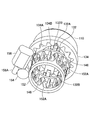
- FIG. 5 and 6 are diagrams showing an internal configuration of the rotation operation device 100 according to the embodiment.
- FIG. 5 is a perspective view of the rotary operation device 100 when viewed from above.
- FIG. 6 is a perspective view of the rotary operation device 100 when viewed from below.
- the rotation member 152 is rotationally driven by the motor 156 to move the pressing portion 152A provided on the rotation member 152 in the circumferential direction.
- the target stopper 146 is pushed upward by the pressing portion 152A of the rotating member 152, and the movement path of the restriction portion 132B in the circumferential direction is blocked.
- the rotation operation device 100 of the present embodiment can limit the rotation operation of the plunger 132, that is, the rotation operation of the operation knob 110 at a desired position.
- the stopper 146 closest to the counterclockwise direction from the current position of the restricting portion 132B of the plunger 132 is the target. It becomes the stopper 146, and the stopper 146 may be pushed upward.
- the stopper 146 closest to the clockwise direction from the current position of the restricting portion 132B of the plunger 132 is the target. It becomes the stopper 146, and the stopper 146 may be pushed upward.
- the contact surface of the pressing portion 152A with the stopper 146 is convex so that the stopper 146 can be smoothly pushed upward by the circumferential movement of the pressing portion 152A.
- the contact surface of the stopper 146 with the pressing portion 152A is curved in a convex shape.
- the plurality of stoppers 146 arranged side by side in the circumferential direction are sequentially pushed upward by the pressing portion 152A provided on the rotary member 152. ing. Therefore, in the rotary operation device 100 of the present embodiment, even if the motor 156 abnormally operates and the rotating member 152 automatically rotates, the pressing portion 152A moves in the circumferential direction and the rotating member 152 rotates. The plurality of stoppers 146 arranged side by side in the direction are simply pushed upward by the pressing portion 152A, and thus the operation knob 110 does not rotate against the user's intention.
- the rotation operating device 100 of the present embodiment controls the rotation angle of the rotating member 152 by driving the motor 156 under the control of the controller.
- the controller needs to obtain the current rotation angle of the restriction portion 132B and the current rotation angle of each pressing portion 152A in order to limit the rotation of the operation knob 110.
- the rotation operation device 100 is provided with a sensor that detects the current rotation angle of the plunger 132 and a sensor that detects the current rotation angle of the rotating member 152, and outputs the detection value of each sensor to the controller. Thereby, the controller can detect the current rotation angles of the plunger 132 and the rotating member 152.
- the controller can easily obtain the current rotation angle of the restriction unit 132B based on the current rotation angle of the plunger 132.
- the controller easily obtains the current rotation angle of each pressing portion 152A based on the current rotation angle of the rotating member 152. be able to.
- the controller selects any one of the stoppers 146 as the stopper 146 for restricting the rotation of the operation knob 110 based on the current rotation angle of the restriction unit 132B.
- the controller uses, as the stopper 146 for limiting the rotation of the operation knob 110, the stopper 146 that is closest to the direction in which the rotation of the operation knob 110 is limited (hereinafter, referred to as “regulation target rotation direction”) from the regulation portion 132B. select.
- the controller causes one of the pressing portions 152A to move to a position corresponding to the selected stopper 146 by rotationally driving the rotating member 152 by the motor 156 based on the current rotation angle of each pressing portion 152A.
- the controller selects the pressing portion 152A closest to the position corresponding to the selected stopper 146 among the four pressing portions 152A provided at 90° intervals on the rotating member 152 to the selected stopper 146. Move to the corresponding position.
- the protrusion 132A of the plunger 132 is fitted into the valley 134B of the feeling cam 134 each time the operation knob 110 is rotated by a predetermined angle, as shown in FIG. As a result, the rotation of the operation knob 110 is stopped.
- the operation knob 110 is simply pushed up by pushing up the stopper 146 arranged at a position corresponding to the rotation angle.
- a plurality of stoppers 146 are arranged at appropriate intervals in the circumferential direction so that the rotation of can be restricted.
- a stopper 146 is arranged inside each of the plurality of cam lobes 134A (on the rotation center axis side). That is, the installation number of the cam crests 134A is the same as the installation number of the stoppers 146, and the installation angle of the cam crests 134A and the installation angle of the stoppers 146 are the same.
- 16 cam ridges 134A are formed on the inner peripheral surface of the feeling cam 134 at intervals of 22.5°.
- the rotary operation device 100 of the present embodiment is fitted into the valley portion 134B of the feeling cam 134 every time the operation knob 110 is rotated by 22.5°, and the rotation of the operation knob 110 is stopped. It is supposed to do.
- 16 stoppers 146 are arranged at intervals of 22.5° in the circumferential direction according to the number of installation and the installation angle of the cam crests 134A.
- the rotary operation device 100 has the restriction portion 132B of the plunger 132 provided with two stoppers regardless of the rotation angle of the operation knob 110. It can be arranged at a position sandwiched by 146. Therefore, by pushing up one of the two stoppers 146 in the clockwise direction, the one stopper 146 can limit the rotation of the operation knob 110 in the clockwise direction, and the counterclockwise rotation can be achieved. By merely pushing up the other stopper 146 in the direction, the other stopper 146 can limit the rotation of the operation knob 110 in the counterclockwise direction.
- each of the operation knob 110, the operation feeling imparting mechanism 130, the stopper mechanism 140, and the drive mechanism 150 has the same shape when rotated by 180°. It has a rotationally symmetric structure.
- the stopper 146 is used for the one restricting portion 132B of the plunger 132 and the other restricting portion 132B of the plunger 132.
- the movement path in the circumferential direction can be blocked. That is, the rotation operation device 100 of the present embodiment can stably limit the rotation of the operation knob 110 at two locations in the circumferential direction of the operation knob 110.
- the operation knob 110 that is rotationally operated and the rotation system of the operation knob 110 (the rotation system of the operation knob 110 is integrated with or separate from the operation knob 110). It is provided and includes all members that rotate with the rotation of the operation knob 110.), a feeling cam 134 that gives an operation feeling to the rotating operation of the operation knob 110, and a motor 156 can be rotationally driven.
- the rotary member 152 and a plurality of stoppers 146 arranged so as to be movable between the outer side and the inner side of the movement path in the circumferential direction of the rotation system of the operation knob 110 are provided, and the rotation member 152 projects toward the stopper 146.
- the stopper located at a position corresponding to the pressing portion 152A among the plurality of stoppers 146 by the pressing portion 152A. Only 146 is moved from the outer side to the inner side of the movement path in the circumferential direction of the rotation system of the operation knob 110, and the stopper 146 is engaged with the rotation system of the operation knob 110.
- the rotary operation device 100 of the present embodiment even if the motor 156 abnormally operates and the rotating member 152 automatically rotates, the stopper 146 is only pushed upward by the pressing portion 152A. Therefore, the operation knob 110 does not rotate against the intention of the user. Therefore, according to the present embodiment, it is possible to provide a highly safe rotation operation device 100 in which the operation knob 110 does not automatically rotate even when the motor 156 operates abnormally. it can.
- the rotary operation device 100 of the present embodiment includes a plurality of stoppers 146 arranged side by side in a ring shape along the circumferential direction of the rotary member 152.
- the rotary operation device 100 of the present embodiment selectively uses the arbitrary one of the stoppers 146 (for example, the stopper 146 according to the rotation angle of the operation knob 110) to operate the operation knob.
- the rotation of 110 can be limited.
- the rotary operation device 100 of the present embodiment even if the motor 156 abnormally operates and the rotating member 152 automatically rotates, the plurality of stoppers 146 are sequentially moved upward by the pressing portion 152A. It is only pushed up, and therefore the operation knob 110 does not rotate against the user's intention. Therefore, according to the present embodiment, it is possible to provide a highly safe rotation operation device 100 in which the operation knob 110 does not automatically rotate even when the motor 156 operates abnormally. it can.
- the rotary member 152 has a plurality of pressing portions 152A arranged at predetermined intervals along the circumferential direction of the rotary member 152.
- the rotary operation device 100 of the present embodiment selectively uses one arbitrary pressing portion 152A (for example, the pressing portion 152A closest to the stopper 146) of the plurality of pressing portions 152A, The stopper 146 can be pushed upward.
- the rotary member 152 has an external gear 152B that rotates the rotary member 152 by receiving the rotational force of the motor 156, on the outer peripheral surface of the rotary member 152.
- the rotation operating device 100 of the present embodiment can increase the reduction ratio between the drive shaft 156A of the motor 156 and the rotating member 152, that is, the drive torque of the drive shaft 156A of the motor 156 can be made relatively small. Therefore, a relatively small motor 156 can be used.
- the stopper 146 is engaged with the plunger 132 to limit the rotation of the operation knob 110.
- the present invention is not limited to this, and at least the stopper 146 is pushed up. Any structure may be adopted as long as it can engage with the rotation system of the operation knob 110 and limit the rotation of the operation knob 110.
- a configuration may be adopted in which the stopper 146 is directly engaged with the operation knob 110.
- a configuration may be adopted in which the stopper 146 is engaged with another member that rotates together with the operation knob 110.
- the stopper 146 and the rotating member 152 are arranged below the rotating system of the operation knob 110, and the stopper 146 is pushed upward by the pressing portion 152A of the rotating member 152 to cause the stopper.
- the configuration in which the rotation of the operation knob 110 is restricted by engaging the rotation system of the operation knob 110 with 146 is adopted, the invention is not limited to this.
- the stopper 146 and the rotating member 152 are arranged on the outer side in the radial direction of the rotating system of the operation knob 110, and the stopper 146 is pushed in the rotation center axis direction by the pressing portion 152A of the rotating member 152 to move the stopper 146.
- a configuration may be adopted in which the rotation of the operation knob 110 is restricted by engaging with the rotation system.
- the rotating member 152 is provided with the four pressing portions 152A, but the present invention is not limited to this. It may be provided.
- the pressing portion 152A of the rotating member 152 is provided at the pitch of the two adjacent stoppers 146, and the circumferential movement path of the rotating system of the operation knob 110 is simultaneously blocked by the two stoppers 146 from both directions, so that You may make it lock so that rotation operation cannot be performed.
- Rotating Operation Device 110 Operating Knob 120 Case 130 Operation Feeling Mechanism 132 Plunger 132A Projection 132B Restriction Part 134 Feeling Cam 134A Cam Mountain 134B Valley 140 Stopper Mechanism 142 Stopper Holder 144 Spring 146 Stopper 150 Drive Mechanism 152 Rotating Member 152A Pressing Part 152B External gear 154 Gear 156 Motor L Rotating shaft
Landscapes
- Physics & Mathematics (AREA)
- General Physics & Mathematics (AREA)
- Engineering & Computer Science (AREA)
- Automation & Control Theory (AREA)
- Mechanical Control Devices (AREA)
- Arrangement Or Mounting Of Control Devices For Change-Speed Gearing (AREA)
Abstract
回転操作装置は、回転操作される操作ノブと、操作ノブの回転操作とともに回転する操作ノブと一体または別体に設けられた操作ノブの回転系と、回転操作に対して操作感を付与するフィーリングカムと、モータにより回転駆動が可能な回転部材と、操作ノブの回転系の周方向の移動経路の外側と内側との間を移動可能に配置された複数のストッパとを備え、回転部材は、ストッパに向かって突出して設けられた押圧部を有し、当該回転部材の回転駆動に伴って押圧部が移動したとき、押圧部によって複数のストッパのうち当該押圧部と対応する位置にあるストッパのみを操作ノブの回転系の周方向の移動経路の外側から内側へと移動させ、当該ストッパを操作ノブの回転系に係合させる。
Description
本発明は、回転操作装置に関する。
従来、例えば、自動車等の車両に搭載される操作装置として、操作ノブによる回転操作によって、変速機のシフトチェンジを電気的に制御することが可能な回転操作装置が知られている。
また、このような回転操作装置に関し、所定の条件を満たしたとき(例えば、現在のシフトポジションが、シフトパターンにおける左端または右端のシフトポジションにあるとき)に、モータの駆動によって操作ノブの回転を制限することができるようにした技術が考案されている。
例えば、下記特許文献1には、回転操作可能な回転つまみに設けられた当接カムをストッパ装置に当接させることにより、回転つまみの回転角を制御することが可能な操作装置に関し、モータの駆動によってストッパ装置を回転させることで、当接カムとストッパ装置との当接位置を変化させることができるようにした技術が開示されている。
また、下記特許文献2には、回転操作可能なノブに設けられた突起部を第1係合部および第2係合部に当接させることにより、ノブの変位を制御することが可能なシフト装置に関し、モータの駆動によって第1カムおよび第2カムを回転させることで、突起部と第1係合部および第2係合部との当接位置を変化させることができるようにした技術が開示されている。
しかしながら、上記特許文献1の技術では、モータが異常動作した場合、ストッパ装置が回転つまみの当接カムを周方向に押し込んでしまうことにより、回転つまみが自動的に回転してしまい、その結果、シフトチェンジがユーザの意図に反して行われてしまう虞がある。
同様に、上記特許文献2の技術では、モータが異常動作した場合、第1カムまたは第2カムがノブの突起部を周方向に押し込んでしまうことにより、ノブが自動的に回転してしまい、その結果、シフトチェンジがユーザの意図に反して行われてしまう虞がある。
このようなことから、発明者は、モータが異常動作した場合であっても、操作ノブが自動的に回転してしまうことがない、安全性の高い回転操作装置の必要性を見出した。
一実施形態の回転操作装置は、回転操作される操作ノブと、操作ノブの回転操作とともに回転する操作ノブと一体または別体に設けられた操作ノブの回転系と、回転操作に対して操作感を付与するフィーリングカムと、モータにより回転駆動が可能な回転部材と、操作ノブの回転系の周方向の移動経路の外側と内側との間を移動可能に配置された複数のストッパとを備え、回転部材は、ストッパに向かって突出して設けられた押圧部を有し、当該回転部材の回転駆動に伴って押圧部が移動したとき、押圧部によって複数のストッパのうち当該押圧部と対応する位置にあるストッパのみを操作ノブの回転系の周方向の移動経路の外側から内側へと移動させ、当該ストッパを操作ノブの回転系に係合させる。
一実施形態によれば、モータが異常動作した場合であっても、操作ノブが自動的に回転してしまうことがない、安全性の高い回転操作装置を提供することができる。
以下、図面を参照して、一実施形態について説明する。なお、以降の説明では、便宜上、図中Z軸方向を、上下方向(ケース120の高さ方向)とし、図中X軸方向を、前後方向(ケース120の短手方向)とし、図中Y軸方向を、左右方向(ケース120の長手方向)とする。
(回転操作装置100の概要)
図1は、一実施形態に係る回転操作装置100の外観斜視図である。図2は、一実施形態に係る回転操作装置100の平面図である。図3は、一実施形態に係る回転操作装置100の側面図である。
図1は、一実施形態に係る回転操作装置100の外観斜視図である。図2は、一実施形態に係る回転操作装置100の平面図である。図3は、一実施形態に係る回転操作装置100の側面図である。
図1~図3に示す回転操作装置100は、自動車等の車両の車内において、運転席の近傍に設置される回転操作装置であって、車両に搭載された変速機のシフトチェンジを電気的に制御するための回転操作装置である。回転操作装置100は、変速機を機械的に制御するものではなく、シフト操作に応じた制御信号を外部に出力することによって変速機を電気的に制御する、いわゆるシフトバイワイヤ方式を採用している。
なお、回転操作装置100は、変速機のシフトチェンジ以外の目的に用いられてよく、車両以外の機器(例えば、航空機、鉄道車両、ゲーム機、リモコン等)に用いられてもよい。また、回転操作装置100は、実際には、シフト操作に応じた電気信号を出力するための電気的な構成を有しているが、本実施形態では、この電気的な構成についての図示および説明を省略することとする。
図1~図3に示すように、回転操作装置100は、直方体形状を有するケース120の上面から、円柱状の操作ノブ110が突出した、全体形状をなしている。また、回転操作装置100は、上方(図中Z軸正方向)からの平面視において、反時計回り方向(図2に示す矢印D1方向)および時計回り方向(図2に示す矢印D2方向)のそれぞれの方向に、操作ノブ110を回転操作することが可能である。
回転操作装置100は、操作ノブ110による回転操作により、変速機のシフトポジションを、複数のシフトポジション(例えば、P,R,N,D,S等)のいずれかに切り替えることが可能である。
回転操作装置100は、操作感付与機構130が設けられている。これにより、回転操作装置100は、所定の角度の回転操作がなされる毎に、当該回転操作に対して操作感(いわゆるクリック感)を付与しつつ、変速機のシフトポジションを切り替えることが可能である。すなわち、回転操作装置100は、回転操作の操作者に対して、シフトポジションの切り替えが確実になされたことを、触覚的に把握させることができるようになっている。また、回転操作装置100は、図示しない操作ノブ110の表示装置により、いずれのシフトポジションにあるかを操作者に対して表示することができる。
(回転操作装置100の構成)
図4は、一実施形態に係る回転操作装置100の分解斜視図である。図4に示すように、回転操作装置100は、図中上方から順に、操作ノブ110、操作感付与機構130、ストッパ機構140、駆動機構150、およびケース120を備えて構成されている。
図4は、一実施形態に係る回転操作装置100の分解斜視図である。図4に示すように、回転操作装置100は、図中上方から順に、操作ノブ110、操作感付与機構130、ストッパ機構140、駆動機構150、およびケース120を備えて構成されている。
操作ノブ110は、ケース120の上面から突出してZ軸に沿って設定された回転軸Lを中心に回転自在に設けられた円柱状の部材である。操作ノブ110は、操作者による回転操作がなされることにより、上方(図中Z軸正方向)からの平面視において、反時計回り方向または時計回り方向に回転する。
操作感付与機構130は、操作ノブ110の回転操作に対して操作感を付与するための機構である。操作感付与機構130は、プランジャ132およびフィーリングカム134を有する。
フィーリングカム134は、操作ノブ110の回転軸Lと同軸上に配置される環状の部材である。フィーリングカム134の内周面には、回転軸Lに向って突出した複数のカム山134Aが、当該内周面に沿って連続的に設けられている。フィーリングカム134の内周面において、隣接する2つのカム山134Aの間には、谷部134Bが形成されている。なお、フィーリングカム134は、ケース120の内部において任意の固定手段(図示省略)によって回転しないように固定されている。
プランジャ132は、フィーリングカム134の内側に設けられている。プランジャ132は、水平方向(回転軸L方向(Z軸方向)と直交する方向)に延在する柱状の部材である。プランジャ132は、操作ノブ110の底部110Aと連結されており、操作ノブ110とともに回転する。プランジャ132の両端面には、半径方向における外側に向って突出した突起部132Aが設けられている。突起部132Aは、プランジャ132の長手方向に伸縮可能であり、且つ、プランジャ132の内部に設けられたコイルばね(図示省略)によって、プランジャ132の長手方向における外側に向って付勢されている。突起部132Aは、フィーリングカム134の内周面に形成された谷部134Bに収まる突起形状を有している。
突起部132Aは、操作ノブ110の回転に伴って、フィーリングカム134の内周面に沿って伸縮を繰り返しながら移動する。突起部132Aは、谷部134Bからカム山134Aの頂部に至るまでの間は、カム山134Aによって回転中心軸方向に徐々に押圧される。これにより、操作ノブ110の回転操作に係る負荷は、徐々に増加する。
突起部132Aは、カム山134Aの頂部を越えると、突起部132Aを付勢するコイルばねの弾性復帰力により、突起部132Aが外側方向へ伸張する。そして、突起部132Aは、操作ノブ110の回転を付勢しつつ、谷部134Bに滑り込む。このとき、操作ノブ110の回転操作に係る負荷は、急激に減少する。そして、突起部132Aは、谷部134Bの底部に達すると、操作ノブ110の回転を急停止させる。
操作感付与機構130は、このように操作ノブ110の回転操作に係る負荷を変化させることにより、操作ノブ110の回転操作に対して操作感(いわゆるクリック感)を付与するとともに、操作ノブ110の回転操作が終了すると、操作ノブ110を谷部134Bの位置で所定のポジションに保持する。
なお、プランジャ132の底面における両端部には、プランジャ132の長手方向における外側に向って突出した規制部132B(操作ノブの回転系の一例)が設けられている。規制部132Bは、回転部材152の押圧部152Aによって上方に押し上げられたストッパ146が、当該規制部132Bの側面に当接することにより、プランジャ132の回転を制限する。プランジャ132は操作ノブ110に連結されているため、プランジャ132の回転が制限されると、操作ノブ110の回転も制限されることとなる。
ストッパ機構140は、ストッパホルダ142、複数のストッパ146、およびコイルスプリング144を有する。ストッパホルダ142は、操作ノブ110、フィーリングカム134、および回転部材152とともに回転軸Lに関して同軸上に配置される環状の部材である。ストッパホルダ142は、当該ストッパホルダ142を上下方向に貫通する複数の貫通孔142Aが、周方向に沿って並べて設けられている。ストッパホルダ142は、各貫通孔142Aにストッパ146の上部が貫通することにより、複数のストッパ146の上部を上下方向にスライド可能に支持する。
ストッパ146は、ストッパホルダ142に形成された貫通孔142A内を上下方向にスライド可能に設けられる棒状の部材である。ストッパ146は、当該ストッパに対応する位置に、回転部材152の押圧部152Aが移動してきたときに、一端部が当該押圧部152Aによって上方に押し上げられ、他端部がプランジャ132の規制部132Bの周方向の移動経路の内部へ侵入する。これにより、ストッパ146は、回転操作されたプランジャ132の規制部132Bと係合して、周方向への移動経路を遮断し、よって、操作ノブ110の回転操作を制限する。図4に示すように、本実施形態の回転操作装置100は回転部材152の周方向に沿って環状に並べて配置された複数のストッパ146を備える。
なお、簡略化のため、図5、図6では図示を省略しているが、図4に示すように、本実施形態の回転操作装置100は、各ストッパ146に対して、コイルスプリング144が設けられている。コイルスプリング144は、ストッパホルダ142の下面とストッパ146の短手方向に延びる支持部との間に挟持され、ストッパ146を下方へ付勢する。コイルスプリング144は、ストッパ146が上方に押し上げられると、ストッパホルダ142の下面とストッパ146の支持部との間で押し縮められる。コイルスプリング144は、ストッパ146の押し上げが解除されると、弾性復帰力によって、ストッパ146を下方へ押し下げ、これにより、ストッパ146は、プランジャ132の規制部132Bの周方向の移動経路の外部へと退避する。
駆動機構150は、回転部材152、ギヤ154、およびモータ156を備える。回転部材152は、回転軸Lに関してストッパホルダ142と同軸上に配置され、且つ、ストッパホルダ142と同一半径を有する環状の部材である。回転部材152は、当該回転部材152の外周面の全域に亘って形成された外歯車152Bを有する。外歯車152Bは、ギヤ154と噛み合っており、モータ156からの回転力を、ギヤ154を介して受けることにより、回転部材152を回転させる。回転部材152の上端面は、複数のストッパ146の各々の下端部が当接することにより、複数のストッパ146の各々の下端部を支持する。回転部材152の上端面には、上方のストッパ146に向って突出した押圧部152Aが設けられている。特に、本実施形態の回転操作装置100は、回転部材152の上端面に対し、4つの押圧部152Aが、所定の間隔の一例として90°間隔を有して設けられている。押圧部152Aは、回転部材152に伴って回転部材152の円周上を移動し、複数のストッパ146のうち押圧部152Aの位置に対応したストッパ146のみを順次押し上げる。押圧部152Aは、図示しない回転部材152の回転角度を検知するセンサにより、操作ノブ110の回転を制限する対象とされたストッパ146の下側で当接する位置に移動し、当該ストッパ146を上方へ押し上げることにより、当該ストッパ146の上端部によって、プランジャ132の規制部132Bと係合することで周方向への移動経路を遮断する。これにより、押圧部152Aは、所望の位置で操作ノブ110の回転操作を係止することができる。
ギヤ154は、モータ156の駆動軸156Aの外周面に形成された外歯車(図示省略)と、回転部材152の外周面に形成された外歯車152Bとに噛み合っており、モータ156の回転力を、回転部材152に伝達する。モータ156は、コントローラ(図示省略)によって駆動軸156Aの回転が制御され、ギヤ154を介して、回転部材152を回転させる。
ケース120は、直方体をなす箱状の部材である。ケース120は、各構成部品(操作感付与機構130、ストッパ機構140、駆動機構150)が内部に組み込まれる。ケース120の上面には円形の開口部120Aが形成されており、操作ノブ110の底面側の一部を貫通させて、操作ノブ110を回転可能に保持した状態で、操作ノブ110とプランジャ132とを連結できるようになっている。なお、ケース120は、直方体に限らず、如何なる形状であってもよい。また、ケース120は、実際には、各構成部品を保持する保持構造、各構成部品の動作をガイドするガイド構造等を内部に有しているが、本実施形態では、便宜上、これらの図示を省略する。
(回転操作装置100の内部構成および動作)
図5および図6は、一実施形態に係る回転操作装置100の内部構成を示す図である。図5は、回転操作装置100を上方から見たときの斜視図である。図6は、回転操作装置100を下方から見たときの斜視図である。
図5および図6は、一実施形態に係る回転操作装置100の内部構成を示す図である。図5は、回転操作装置100を上方から見たときの斜視図である。図6は、回転操作装置100を下方から見たときの斜視図である。
図5および図6では、ケース120の図示を省略して、回転操作装置100の内部構成を示している。また、図5および図6では、回転操作装置100において、回転部材152の押圧部152Aによって、一部のストッパ146が上方へ押し上げられ、当該ストッパ146によって操作ノブ110の反時計回り方向への回転操作が制限されている状態を示している。
図5および図6に示すように、本実施形態の回転操作装置100は、モータ156によって回転部材152を回転駆動させて、回転部材152に設けられた押圧部152Aを周方向に移動させることにより、回転部材152の押圧部152Aによって対象のストッパ146を上方へ押し上げて、規制部132Bの周方向への移動経路を遮断する。これにより、本実施形態の回転操作装置100は、プランジャ132の回転操作を制限し、すなわち、操作ノブ110の回転操作を所望の位置で制限することができる。
操作ノブ110に対して、現状のポジション状態からの反時計回り方向への回転操作を制限する場合には、現状のプランジャ132の規制部132Bの位置から反時計回り方向に最も近いストッパ146が対象のストッパ146となり、このストッパ146を上方へ押し上げればよい。反対に、操作ノブ110に対して、現状のポジション状態からの時計回り方向への回転を制限する場合には、現状のプランジャ132の規制部132Bの位置から時計回り方向に最も近いストッパ146が対象のストッパ146となり、このストッパ146を上方へ押し上げればよい。
本実施形態の回転操作装置100は、押圧部152Aの周方向への移動により、ストッパ146を上方へスムーズに押し上げることができるように、押圧部152Aにおけるストッパ146との当接面が凸状に湾曲しており、ストッパ146における押圧部152Aとの当接面が凸状に湾曲している。
本実施形態の回転操作装置100は、回転部材152が回転する際、周方向に並べて配置された複数のストッパ146が、回転部材152に設けられた押圧部152Aによって順次上方に押し上げられるようになっている。このため、本実施形態の回転操作装置100は、万が一、モータ156が異常動作して、回転部材152が自動的に回転した場合であっても、押圧部152Aが周方向に移動して、周方向に並べて配置された複数のストッパ146が、当該押圧部152Aによって順次上方に押し上げられるだけであり、したがって、ユーザの意図に反して操作ノブ110が回転することはない。
本実施形態の回転操作装置100は、コントローラからの制御によりモータ156を駆動することによって、回転部材152の回転角度を制御する。
コントローラは、操作ノブ110の回転を制限するために、規制部132Bの現在の回転角度と、各押圧部152Aの現在の回転角度とを求める必要がある。例えば、回転操作装置100に対し、プランジャ132の現在の回転角度を検知するセンサと、回転部材152の現在の回転角度を検知するセンサとを設け、各センサの検出値をコントローラへ出力する。これにより、コントローラは、プランジャ132および回転部材152の現在の回転角度を検知することができる。
規制部132Bはプランジャ132の所定の位置に設けられているため、コントローラは、プランジャ132の現在の回転角度に基づいて、規制部132Bの現在の回転角度を容易に求めることができる。同様に、各押圧部152Aは回転部材152の所定の位置に設けられているため、コントローラは、回転部材152の現在の回転角度に基づいて、各押圧部152Aの現在の回転角度を容易に求めることができる。
コントローラは、規制部132Bの現在の回転角度に基づいて、操作ノブ110の回転を制限するためのストッパ146として、いずれかのストッパ146を選択する。例えば、コントローラは、操作ノブ110の回転を制限するためのストッパ146として、規制部132Bから、操作ノブ110の回転を制限する方向(以下「規制対象回転方向」と示す)に最も近いストッパ146を選択する。
そして、コントローラは、各押圧部152Aの現在の回転角度に基づいて、モータ156により回転部材152を回転駆動させることにより、選択されたストッパ146に対応する位置に、いずれかの押圧部152Aを移動させる。例えば、コントローラは、回転部材152に90°間隔で設けられた4つの押圧部152Aのうち、選択されたストッパ146に対応する位置に最も近い位置にある押圧部152Aを、選択されたストッパ146に対応する位置に移動させる。
これにより、回転部材152の回転駆動が最小限の距離で完了し、押圧部152Aによって、選択されたストッパ146が上方に押し上げられ、当該ストッパ146により、規制部132Bの規制対象回転方向への移動経路が遮断される。その結果、操作ノブ110の規制対象回転方向への回転操作の制限が最小限の時間で完了される。
本実施形態の回転操作装置100は、操作ノブ110による所定角度の回転操作がなされる毎に、図6に示すように、プランジャ132の突起部132Aが、フィーリングカム134の谷部134Bに嵌合することにより、操作ノブ110の回転が停止する。本実施形態の回転操作装置100は、操作ノブ110がいずれの回転角度で停止している場合であっても、その回転角度に対応する位置に配置されたストッパ146を押し上げるだけで、操作ノブ110の回転を制限することができるように、複数のストッパ146が周方向に適切な間隔で配置されている。
具体的には、本実施形態の回転操作装置100は、図6に示すように、複数のカム山134Aの各々の内側(回転中心軸側)に、ストッパ146が配置されている。すなわち、カム山134Aの設置数と、ストッパ146の設置数とは同数であり、且つ、カム山134Aの設置角度と、ストッパ146の設置角度とは同角度である。
例えば、本実施形態の回転操作装置100は、フィーリングカム134の内周面には、22.5°間隔で16個のカム山134Aが形成されている。これにより、本実施形態の回転操作装置100は、操作ノブ110による22.5°の回転操作がなされる毎に、フィーリングカム134の谷部134Bに嵌合し、操作ノブ110の回転が停止するようになっている。そして、本実施形態の回転操作装置100は、カム山134Aの設置数および設置角度に合わせて、16個のストッパ146が、周方向に22.5°間隔で配置されている。
これにより、本実施形態の回転操作装置100は、操作ノブ110がいずれの回転角度で停止している場合であっても、図6に示すように、プランジャ132の規制部132Bを、2つのストッパ146で挟み込まれる位置に配置することができる。したがって、2つのストッパ146のうち、時計回り方向にある一方のストッパ146を押し上げるだけで、当該一方のストッパ146により、操作ノブ110の時計回り方向への回転を制限することができ、反時計回り方向にある他方のストッパ146を押し上げるだけで、当該他方のストッパ146により、操作ノブ110の反時計回り方向への回転を制限することができる。
また、図6に示すように、本実施形態の回転操作装置100は、操作ノブ110、操作感付与機構130、ストッパ機構140、および駆動機構150の各々が、180°回転させたときに同一形状となる回転対称構造を有している。これにより、本実施形態の回転操作装置100は、図6に示すように、プランジャ132が有する一方の規制部132Bと、プランジャ132が有する他方の規制部132Bとに対して同様に、ストッパ146によって周方向への移動経路を遮断することができる。すなわち、本実施形態の回転操作装置100は、操作ノブ110の周方向における2か所で、操作ノブ110の回転を安定的に制限することができる。
以上説明したように、本実施形態の回転操作装置100は、回転操作される操作ノブ110と、操作ノブ110の回転系(操作ノブ110の回転系とは、操作ノブ110と一体または別体に設けられ、操作ノブ110の回転に伴って回転する部材全般を含むものである。)と、操作ノブ110の回転操作に対して操作感を付与するフィーリングカム134と、モータ156により回転駆動が可能な回転部材152と、操作ノブ110の回転系の周方向の移動経路の外側と内側との間を移動可能に配置された複数のストッパ146とを備え、回転部材152は、ストッパ146に向かって突出して設けられた押圧部152Aを有し、当該回転部材152の回転駆動に伴って押圧部152Aが移動したとき、押圧部152Aによって複数のストッパ146のうち当該押圧部152Aと対応する位置にあるストッパ146のみを操作ノブ110の回転系の周方向の移動経路の外側から内側へと移動させ、当該ストッパ146を操作ノブ110の回転系に係合させる。
これにより、本実施形態の回転操作装置100は、万が一、モータ156が異常動作して、回転部材152が自動的に回転した場合であっても、ストッパ146が押圧部152Aによって上方に押し上げられるだけであり、したがって、ユーザの意図に反して操作ノブ110が回転することはない。このため、本実施形態によれば、モータ156が異常動作した場合であっても、操作ノブ110が自動的に回転してしまうことがない、安全性の高い回転操作装置100を提供することができる。
特に、本実施形態の回転操作装置100は、回転部材152の周方向に沿って環状に並べて配置された複数のストッパ146を備える。
これにより、本実施形態の回転操作装置100は、複数のストッパ146のうちの任意の一のストッパ146(例えば、操作ノブ110の回転角度に応じたストッパ146)を選択的に用いて、操作ノブ110の回転を制限することができる。
加えて、本実施形態の回転操作装置100は、万が一、モータ156が異常動作して、回転部材152が自動的に回転した場合であっても、複数のストッパ146が押圧部152Aによって順次上方に押し上げられるだけであり、したがって、ユーザの意図に反して操作ノブ110が回転することはない。このため、本実施形態によれば、モータ156が異常動作した場合であっても、操作ノブ110が自動的に回転してしまうことがない、安全性の高い回転操作装置100を提供することができる。
また、本実施形態の回転操作装置100において、回転部材152は、当該回転部材152の周方向に沿って所定の間隔を有して配置された複数の押圧部152Aを有する。
これにより、本実施形態の回転操作装置100は、複数の押圧部152Aのうちの任意の一の押圧部152A(例えば、ストッパ146に最も近い位置にある押圧部152A)を選択的に用いて、ストッパ146を上方に押し上げることができる。
また、本実施形態の回転操作装置100において、回転部材152は、モータ156の回転力を受けて当該回転部材152を回転させる外歯車152Bを、当該回転部材152の外周面に有する。
これにより、本実施形態の回転操作装置100は、モータ156の駆動軸156Aと回転部材152との減速比を大きくすることができ、すなわち、モータ156の駆動軸156Aの駆動トルクを比較的小さくすることができるため、比較的小型のモータ156を用いることができる。
以上、本発明の一実施形態について詳述したが、本発明はこれらの実施形態に限定されるものではなく、特許請求の範囲に記載された本発明の要旨の範囲内において、種々の変形又は変更が可能である。
例えば、上記実施形態の回転操作装置100では、ストッパ146をプランジャ132に係合させることにより、操作ノブ110の回転を制限する構成を採用しているが、これに限らず、少なくともストッパ146が押し上げられることによって操作ノブ110の回転系に係合し、操作ノブ110の回転を制限することが可能な構成であれば、如何なる構成を採用してもよい。例えば、ストッパ146を直接的に操作ノブ110に係合させる構成を採用してもよい。また、例えば、ストッパ146を操作ノブ110と共に回転する別の部材に係合させる構成を採用してもよい。
また、上記実施形態の回転操作装置100では、ストッパ146および回転部材152を操作ノブ110の回転系の下方に配置し、ストッパ146を回転部材152の押圧部152Aによって上方に押しこんで、当該ストッパ146を操作ノブ110の回転系に係合させることにより、操作ノブ110の回転を制限する構成を採用しているが、これに限らない。例えば、ストッパ146および回転部材152を操作ノブ110の回転系の半径方向における外側に配置し、ストッパ146を回転部材152の押圧部152Aによって回転中心軸方向に押し込んで、当該ストッパ146を操作ノブ110の回転系に係合させることにより、操作ノブ110の回転を制限する構成を採用してもよい。
また、上記実施形態の回転操作装置100では、回転部材152に4つの押圧部152Aを設けているが、これに限らず、例えば、回転部材152に3つ以下または5つ以上の押圧部152Aを設けるようにしてもよい。例えば、回転部材152の押圧部152Aを隣接する2つのストッパ146のピッチで設け、操作ノブ110の回転系の周方向の移動経路を2つのストッパ146で同時に両方向から遮断して、操作ノブ110の回転操作ができないようにロックするようにしてもよい。
本国際出願は、2018年12月6日に出願した日本国特許出願第2018-228936号に基づく優先権を主張するものであり、当該出願の全内容を本国際出願に援用する。
100 回転操作装置
110 操作ノブ
120 ケース
130 操作感付与機構
132 プランジャ
132A 突起部
132B 規制部
134 フィーリングカム
134A カム山
134B 谷部
140 ストッパ機構
142 ストッパホルダ
144 スプリング
146 ストッパ
150 駆動機構
152 回転部材
152A 押圧部
152B 外歯車
154 ギヤ
156 モータ
L 回転軸
110 操作ノブ
120 ケース
130 操作感付与機構
132 プランジャ
132A 突起部
132B 規制部
134 フィーリングカム
134A カム山
134B 谷部
140 ストッパ機構
142 ストッパホルダ
144 スプリング
146 ストッパ
150 駆動機構
152 回転部材
152A 押圧部
152B 外歯車
154 ギヤ
156 モータ
L 回転軸
Claims (6)
- 回転操作される操作ノブと、
前記操作ノブの回転操作とともに回転する前記操作ノブと一体または別体に設けられた前記操作ノブの回転系と、
前記回転操作に対して操作感を付与するフィーリングカムと、
モータにより回転駆動が可能な回転部材と、
前記操作ノブの回転系の周方向の移動経路の外側と内側との間を移動可能に配置された複数のストッパと
を備え、
前記回転部材は、
前記ストッパに向かって突出して設けられた押圧部を有し、
当該回転部材の前記回転駆動に伴って前記押圧部が移動したとき、前記押圧部によって複数の前記ストッパのうち当該押圧部と対応する位置にある前記ストッパのみを前記操作ノブの回転系の前記周方向の移動経路の外側から内側へと移動させ、当該ストッパを前記操作ノブの回転系に係合させる
ことを特徴とする回転操作装置。 - 前記回転部材の周方向に沿って配置された複数の前記ストッパを備える
ことを特徴とする請求項1に記載の回転操作装置。 - 前記回転部材は、
当該回転部材の周方向に沿って所定の間隔を有して配置された複数の前記押圧部を有する
ことを特徴とする請求項1または2に記載の回転操作装置。 - 前記ストッパは、
前記回転部材の回転軸と同軸上に配置されたストッパホルダによって、前記回転部材の回転軸に沿ってスライド可能に保持されている
ことを特徴とする請求項1から3のいずれか一項に記載の回転操作装置。 - 前記回転部材は、
前記モータの回転力を受けて当該回転部材を回転させる外歯車を、当該回転部材の外周面に有する
ことを特徴とする請求項1から4のいずれか一項に記載の回転操作装置。 - 前記回転部材は、
前記操作ノブの回転軸と同軸上に設けられている
ことを特徴とする請求項1から5のいずれか一項に記載の回転操作装置。
Applications Claiming Priority (2)
| Application Number | Priority Date | Filing Date | Title |
|---|---|---|---|
| JP2018228936A JP2022034085A (ja) | 2018-12-06 | 2018-12-06 | 回転操作装置 |
| JP2018-228936 | 2018-12-06 |
Publications (1)
| Publication Number | Publication Date |
|---|---|
| WO2020116079A1 true WO2020116079A1 (ja) | 2020-06-11 |
Family
ID=70974579
Family Applications (1)
| Application Number | Title | Priority Date | Filing Date |
|---|---|---|---|
| PCT/JP2019/043504 Ceased WO2020116079A1 (ja) | 2018-12-06 | 2019-11-06 | 回転操作装置 |
Country Status (2)
| Country | Link |
|---|---|
| JP (1) | JP2022034085A (ja) |
| WO (1) | WO2020116079A1 (ja) |
Cited By (1)
| Publication number | Priority date | Publication date | Assignee | Title |
|---|---|---|---|---|
| DE102022204022A1 (de) | 2022-04-26 | 2023-10-26 | Signata GmbH | Wählhebelanordnung für ein Automatikgetriebe eines Fahrzeuges |
Citations (3)
| Publication number | Priority date | Publication date | Assignee | Title |
|---|---|---|---|---|
| JPS5226099U (ja) * | 1975-08-15 | 1977-02-23 | ||
| JP2009069931A (ja) * | 2007-09-11 | 2009-04-02 | Alps Electric Co Ltd | 回転式入力装置 |
| KR20180062141A (ko) * | 2016-11-30 | 2018-06-08 | 에스엘 주식회사 | 차량용 변속 장치 |
-
2018
- 2018-12-06 JP JP2018228936A patent/JP2022034085A/ja active Pending
-
2019
- 2019-11-06 WO PCT/JP2019/043504 patent/WO2020116079A1/ja not_active Ceased
Patent Citations (3)
| Publication number | Priority date | Publication date | Assignee | Title |
|---|---|---|---|---|
| JPS5226099U (ja) * | 1975-08-15 | 1977-02-23 | ||
| JP2009069931A (ja) * | 2007-09-11 | 2009-04-02 | Alps Electric Co Ltd | 回転式入力装置 |
| KR20180062141A (ko) * | 2016-11-30 | 2018-06-08 | 에스엘 주식회사 | 차량용 변속 장치 |
Cited By (1)
| Publication number | Priority date | Publication date | Assignee | Title |
|---|---|---|---|---|
| DE102022204022A1 (de) | 2022-04-26 | 2023-10-26 | Signata GmbH | Wählhebelanordnung für ein Automatikgetriebe eines Fahrzeuges |
Also Published As
| Publication number | Publication date |
|---|---|
| JP2022034085A (ja) | 2022-03-03 |
Similar Documents
| Publication | Publication Date | Title |
|---|---|---|
| JP6246183B2 (ja) | シフト装置 | |
| US11364798B2 (en) | Shift device | |
| JP6144722B2 (ja) | 車両用シフト装置 | |
| JP7125196B2 (ja) | シフト装置 | |
| JP6576838B2 (ja) | シフト装置 | |
| US12098768B2 (en) | Rotary shifter | |
| WO2017110593A1 (ja) | シフト装置 | |
| US20240116616A1 (en) | Mounting device for a lever configured for controlling a marine vehicle | |
| JP7108851B2 (ja) | 入力装置 | |
| US20180111507A1 (en) | Power seat operation device and power seat | |
| JP2022034085A (ja) | 回転操作装置 | |
| US10266072B2 (en) | Power seat operation device and power seat | |
| JP2019006137A (ja) | シフト装置 | |
| WO2019054153A1 (ja) | シフト装置 | |
| EP3680747A1 (en) | Operating device | |
| WO2019176364A1 (ja) | シフト装置 | |
| WO2017110592A1 (ja) | シフト装置 | |
| JP2019156369A (ja) | シフト装置 | |
| JP6162589B2 (ja) | シフト装置 | |
| KR20130067762A (ko) | 변속레버의 쉬프트록 장치 | |
| JP7545286B2 (ja) | シフト操作装置 | |
| JP7359644B2 (ja) | レンジ選択機構 | |
| JP2020172172A (ja) | シフト装置 | |
| JP2022149815A (ja) | 回転入力装置 | |
| KR101972971B1 (ko) | 차량용 변속기 제어 장치 |
Legal Events
| Date | Code | Title | Description |
|---|---|---|---|
| 121 | Ep: the epo has been informed by wipo that ep was designated in this application |
Ref document number: 19891892 Country of ref document: EP Kind code of ref document: A1 |
|
| NENP | Non-entry into the national phase |
Ref country code: DE |
|
| 122 | Ep: pct application non-entry in european phase |
Ref document number: 19891892 Country of ref document: EP Kind code of ref document: A1 |
|
| NENP | Non-entry into the national phase |
Ref country code: JP |