WO2020115812A1 - 空気調和機 - Google Patents
空気調和機 Download PDFInfo
- Publication number
- WO2020115812A1 WO2020115812A1 PCT/JP2018/044519 JP2018044519W WO2020115812A1 WO 2020115812 A1 WO2020115812 A1 WO 2020115812A1 JP 2018044519 W JP2018044519 W JP 2018044519W WO 2020115812 A1 WO2020115812 A1 WO 2020115812A1
- Authority
- WO
- WIPO (PCT)
- Prior art keywords
- heat exchanger
- refrigerant
- temperature
- boundary
- upper heat
- Prior art date
Links
Images


Classifications
-
- F—MECHANICAL ENGINEERING; LIGHTING; HEATING; WEAPONS; BLASTING
- F24—HEATING; RANGES; VENTILATING
- F24F—AIR-CONDITIONING; AIR-HUMIDIFICATION; VENTILATION; USE OF AIR CURRENTS FOR SCREENING
- F24F11/00—Control or safety arrangements
- F24F11/30—Control or safety arrangements for purposes related to the operation of the system, e.g. for safety or monitoring
- F24F11/41—Defrosting; Preventing freezing
- F24F11/42—Defrosting; Preventing freezing of outdoor units
-
- F—MECHANICAL ENGINEERING; LIGHTING; HEATING; WEAPONS; BLASTING
- F24—HEATING; RANGES; VENTILATING
- F24F—AIR-CONDITIONING; AIR-HUMIDIFICATION; VENTILATION; USE OF AIR CURRENTS FOR SCREENING
- F24F1/00—Room units for air-conditioning, e.g. separate or self-contained units or units receiving primary air from a central station
- F24F1/06—Separate outdoor units, e.g. outdoor unit to be linked to a separate room comprising a compressor and a heat exchanger
- F24F1/14—Heat exchangers specially adapted for separate outdoor units
- F24F1/16—Arrangement or mounting thereof
-
- F—MECHANICAL ENGINEERING; LIGHTING; HEATING; WEAPONS; BLASTING
- F24—HEATING; RANGES; VENTILATING
- F24F—AIR-CONDITIONING; AIR-HUMIDIFICATION; VENTILATION; USE OF AIR CURRENTS FOR SCREENING
- F24F11/00—Control or safety arrangements
- F24F11/30—Control or safety arrangements for purposes related to the operation of the system, e.g. for safety or monitoring
- F24F11/41—Defrosting; Preventing freezing
-
- F—MECHANICAL ENGINEERING; LIGHTING; HEATING; WEAPONS; BLASTING
- F25—REFRIGERATION OR COOLING; COMBINED HEATING AND REFRIGERATION SYSTEMS; HEAT PUMP SYSTEMS; MANUFACTURE OR STORAGE OF ICE; LIQUEFACTION SOLIDIFICATION OF GASES
- F25B—REFRIGERATION MACHINES, PLANTS OR SYSTEMS; COMBINED HEATING AND REFRIGERATION SYSTEMS; HEAT PUMP SYSTEMS
- F25B13/00—Compression machines, plants or systems, with reversible cycle
-
- F—MECHANICAL ENGINEERING; LIGHTING; HEATING; WEAPONS; BLASTING
- F25—REFRIGERATION OR COOLING; COMBINED HEATING AND REFRIGERATION SYSTEMS; HEAT PUMP SYSTEMS; MANUFACTURE OR STORAGE OF ICE; LIQUEFACTION SOLIDIFICATION OF GASES
- F25B—REFRIGERATION MACHINES, PLANTS OR SYSTEMS; COMBINED HEATING AND REFRIGERATION SYSTEMS; HEAT PUMP SYSTEMS
- F25B39/00—Evaporators; Condensers
- F25B39/02—Evaporators
-
- F—MECHANICAL ENGINEERING; LIGHTING; HEATING; WEAPONS; BLASTING
- F25—REFRIGERATION OR COOLING; COMBINED HEATING AND REFRIGERATION SYSTEMS; HEAT PUMP SYSTEMS; MANUFACTURE OR STORAGE OF ICE; LIQUEFACTION SOLIDIFICATION OF GASES
- F25B—REFRIGERATION MACHINES, PLANTS OR SYSTEMS; COMBINED HEATING AND REFRIGERATION SYSTEMS; HEAT PUMP SYSTEMS
- F25B41/00—Fluid-circulation arrangements
- F25B41/20—Disposition of valves, e.g. of on-off valves or flow control valves
-
- F—MECHANICAL ENGINEERING; LIGHTING; HEATING; WEAPONS; BLASTING
- F25—REFRIGERATION OR COOLING; COMBINED HEATING AND REFRIGERATION SYSTEMS; HEAT PUMP SYSTEMS; MANUFACTURE OR STORAGE OF ICE; LIQUEFACTION SOLIDIFICATION OF GASES
- F25B—REFRIGERATION MACHINES, PLANTS OR SYSTEMS; COMBINED HEATING AND REFRIGERATION SYSTEMS; HEAT PUMP SYSTEMS
- F25B47/00—Arrangements for preventing or removing deposits or corrosion, not provided for in another subclass
- F25B47/02—Defrosting cycles
- F25B47/022—Defrosting cycles hot gas defrosting
-
- F—MECHANICAL ENGINEERING; LIGHTING; HEATING; WEAPONS; BLASTING
- F25—REFRIGERATION OR COOLING; COMBINED HEATING AND REFRIGERATION SYSTEMS; HEAT PUMP SYSTEMS; MANUFACTURE OR STORAGE OF ICE; LIQUEFACTION SOLIDIFICATION OF GASES
- F25B—REFRIGERATION MACHINES, PLANTS OR SYSTEMS; COMBINED HEATING AND REFRIGERATION SYSTEMS; HEAT PUMP SYSTEMS
- F25B2313/00—Compression machines, plants or systems with reversible cycle not otherwise provided for
- F25B2313/025—Compression machines, plants or systems with reversible cycle not otherwise provided for using multiple outdoor units
- F25B2313/0251—Compression machines, plants or systems with reversible cycle not otherwise provided for using multiple outdoor units being defrosted alternately
-
- F—MECHANICAL ENGINEERING; LIGHTING; HEATING; WEAPONS; BLASTING
- F25—REFRIGERATION OR COOLING; COMBINED HEATING AND REFRIGERATION SYSTEMS; HEAT PUMP SYSTEMS; MANUFACTURE OR STORAGE OF ICE; LIQUEFACTION SOLIDIFICATION OF GASES
- F25B—REFRIGERATION MACHINES, PLANTS OR SYSTEMS; COMBINED HEATING AND REFRIGERATION SYSTEMS; HEAT PUMP SYSTEMS
- F25B2313/00—Compression machines, plants or systems with reversible cycle not otherwise provided for
- F25B2313/025—Compression machines, plants or systems with reversible cycle not otherwise provided for using multiple outdoor units
- F25B2313/0253—Compression machines, plants or systems with reversible cycle not otherwise provided for using multiple outdoor units in parallel arrangements
-
- F—MECHANICAL ENGINEERING; LIGHTING; HEATING; WEAPONS; BLASTING
- F25—REFRIGERATION OR COOLING; COMBINED HEATING AND REFRIGERATION SYSTEMS; HEAT PUMP SYSTEMS; MANUFACTURE OR STORAGE OF ICE; LIQUEFACTION SOLIDIFICATION OF GASES
- F25B—REFRIGERATION MACHINES, PLANTS OR SYSTEMS; COMBINED HEATING AND REFRIGERATION SYSTEMS; HEAT PUMP SYSTEMS
- F25B2313/00—Compression machines, plants or systems with reversible cycle not otherwise provided for
- F25B2313/031—Sensor arrangements
- F25B2313/0315—Temperature sensors near the outdoor heat exchanger
-
- F—MECHANICAL ENGINEERING; LIGHTING; HEATING; WEAPONS; BLASTING
- F25—REFRIGERATION OR COOLING; COMBINED HEATING AND REFRIGERATION SYSTEMS; HEAT PUMP SYSTEMS; MANUFACTURE OR STORAGE OF ICE; LIQUEFACTION SOLIDIFICATION OF GASES
- F25B—REFRIGERATION MACHINES, PLANTS OR SYSTEMS; COMBINED HEATING AND REFRIGERATION SYSTEMS; HEAT PUMP SYSTEMS
- F25B2700/00—Sensing or detecting of parameters; Sensors therefor
- F25B2700/21—Temperatures
- F25B2700/2106—Temperatures of fresh outdoor air
-
- F—MECHANICAL ENGINEERING; LIGHTING; HEATING; WEAPONS; BLASTING
- F25—REFRIGERATION OR COOLING; COMBINED HEATING AND REFRIGERATION SYSTEMS; HEAT PUMP SYSTEMS; MANUFACTURE OR STORAGE OF ICE; LIQUEFACTION SOLIDIFICATION OF GASES
- F25B—REFRIGERATION MACHINES, PLANTS OR SYSTEMS; COMBINED HEATING AND REFRIGERATION SYSTEMS; HEAT PUMP SYSTEMS
- F25B2700/00—Sensing or detecting of parameters; Sensors therefor
- F25B2700/21—Temperatures
- F25B2700/2117—Temperatures of an evaporator
- F25B2700/21174—Temperatures of an evaporator of the refrigerant at the inlet of the evaporator
Definitions
- the present invention relates to an air conditioner that simultaneously performs defrosting of an outdoor heat exchanger and indoor heating.
- Patent Document 1 there is an air conditioner that simultaneously performs defrosting of the outdoor heat exchanger and heating of the room (see, for example, Patent Document 1).
- a compressor, a four-way valve, an indoor heat exchanger, a decompression device, and an outdoor heat exchanger are provided with a refrigerant circuit, and a hot gas flows from the discharge side of the compressor to the outdoor heat exchanger.
- a bypass circuit is provided.
- the outdoor heat exchanger has a lower heat exchanger and an upper heat exchanger which are divided into upper and lower refrigerant circuits.
- the control device opens and closes the main circuit opening/closing mechanism and the second expansion device to heat the upper heat exchanger while defrosting the lower heat exchanger, and then defrosting the lower heat exchanger to heat the upper heat exchanger.
- the outdoor heat exchanger has a plurality of paths that are refrigerant passages, and one of the plurality of paths is a cooling inlet side pipe, that is, heating that continues heating while defrosting.
- the path inlet at the time of defrost operation is arranged at the boundary between the upper heat exchanger and the lower heat exchanger.
- Patent Document 1 when the upper heat exchanger is defrosted during heating defrosting, drain water melted in the upper heat exchanger flows down on the heat transfer fins of the outdoor heat exchanger. Further, the lower heat exchanger becomes an evaporator, and when the temperature of the heat exchanger drops to 0° C. or lower, drain water is re-frozen in the lower heat exchanger. After that, when the lower heat exchanger is defrosted, the drain water re-iced in the lower heat exchanger melts, but the upper heat exchanger becomes an evaporator, so the heat of the upper heat exchanger and the lower heat exchanger is Due to conduction, the temperature at the boundary between the upper heat exchanger and the lower heat exchanger is hard to rise. Therefore, there is a problem that the ice re-freezing the drain water grows without melting and inhibits the air flow of the heat transfer fins of the outdoor heat exchanger, resulting in a decrease in heating capacity.
- the present invention has been made to solve the above problems, and suppresses a decrease in heating capacity due to re-freezing of drain water at the boundary between the upper heat exchanger and the lower heat exchanger. It is intended to provide an air conditioner that can do the work.
- the air conditioner according to the present invention includes a compressor for compressing and discharging a refrigerant, an indoor heat exchanger for exchanging heat between the refrigerant and room air, a first throttle device for decompressing the refrigerant, and flow paths arranged in parallel with each other.
- An outdoor heat exchanger configured by an upper heat exchanger and a lower heat exchanger for exchanging heat between a refrigerant and the outside air, and a flow for switching the refrigerant flow to the upper heat exchanger side or the lower heat exchanger side.
- a line switching device is sequentially connected by a pipe, a refrigerant circuit in which a refrigerant circulates, a hot gas bypass pipe connecting the discharge side of the compressor and the flow path switching device, and the upper heat exchange while performing a heating normal operation.
- a controller for performing a heating defrost operation that alternately defrosts the lower heat exchanger and the lower heat exchanger, wherein the outdoor heat exchanger has a plurality of hairpin tubes forming a part of heat transfer piping, and the upper side.
- the heat exchanger serves as a refrigerant inlet when all the hairpin tubes located at the bottom are defrosted, and the lower heat exchanger is where all the hairpin tubes located at the top are defrosted. It becomes the refrigerant inlet.
- the hairpin tubes located at the lowermost stage of the upper heat exchanger and the uppermost stage of the lower heat exchanger that is, all the hairpin tubes located at their boundaries, are defrosted. It becomes the refrigerant inlet. Therefore, it is possible to suppress re-freezing of the drain water at the boundary between the upper heat exchanger and the lower heat exchanger, and it is possible to suppress deterioration of the heating capacity.
- FIG. 1 is a schematic diagram showing a cross section near a boundary between an upper heat exchanger and a lower heat exchanger when the upper heat exchanger of an outdoor heat exchanger of an air conditioner according to Embodiment 1 of the present invention is defrosted. is there.
- the schematic diagram which shows the cross section near the boundary of an upper side heat exchanger and a lower side heat exchanger at the time of defrosting the lower side heat exchanger of the outdoor heat exchanger of the air conditioner which concerns on Embodiment 1 of this invention. Is.
- FIG. 5 is a temperature distribution diagram near the boundary of the outdoor heat exchanger during the heating defrost operation of the air conditioner according to Embodiment 1 of the present invention. It is a refrigerant circuit diagram of the air conditioner which concerns on Embodiment 2 of this invention. It is a refrigerant circuit diagram of the air conditioner which concerns on Embodiment 3 of this invention. It is a refrigerant circuit diagram of the air conditioner which concerns on Embodiment 4 of this invention.
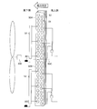
- FIG. 1 is a refrigerant circuit diagram of an air conditioner 100 according to Embodiment 1 of the present invention.
- the air conditioner 100 according to Embodiment 1 includes an outdoor unit 1 and an indoor unit 2, and the outdoor unit 1 and the indoor unit 2 are connected by refrigerant pipes 83, 84 and electric wiring (not shown). It is a separate type.
- the outdoor unit 1 includes a compressor 10, a first flow path switching device 20, a first expansion device 30, a second expansion device 60, a second flow path switching device 70, an outdoor heat exchanger 50, and an outdoor fan. 500, an outside air temperature detection device 200, a first boundary temperature detection device 201, a second boundary temperature detection device 202, and a control device 300.
- the indoor unit 2 includes an indoor heat exchanger 40 and an indoor fan 400.
- the air conditioner 100 has a refrigerant circuit in which a refrigerant circulates.
- the compressor 10, the first flow path switching device 20, the indoor heat exchanger 40, the first expansion device 30, the outdoor heat exchanger 50, and the second flow path switching device 70 are refrigerant pipes 81 to 85, 86A. .About.87A and 86B to 87B, 89 and 91 are sequentially connected.
- Various kinds of refrigerant can be adopted as the refrigerant circulating in the refrigerant circuit, for example, R32 or R410A.
- the discharge side of the compressor 10 and the port A of the second flow path switching device 70 are connected by hot gas bypass pipes 80, 88, and the hot gas bypass pipes 80, 88 are provided with a second expansion device 60. Has been.
- refrigerant pipe 81 One end of the refrigerant pipe 81 is connected to the discharge side of the compressor 10, and the other end branches into a hot gas bypass pipe 80 and a refrigerant pipe 82.
- the refrigerant pipe 82 is connected to the G port of the first flow path switching device 20, and the hot gas bypass pipe 80 is connected to the second expansion device 60.
- the refrigerant pipe 83 connects the H port of the first flow path switching device 20 and the indoor heat exchanger 40.
- the refrigerant pipe 84 connects the indoor heat exchanger 40 and the first expansion device 30.
- the refrigerant pipe 85 is connected to the first expansion device 30, and the other end branches into a refrigerant pipe 86A and a refrigerant pipe 86B.
- the refrigerant pipe 86A is connected to the upper heat exchanger 50A included in the outdoor heat exchanger 50
- the refrigerant pipe 86B is connected to the lower heat exchanger 50B included in the outdoor heat exchanger 50.
- the refrigerant pipe 87A connects the upper heat exchanger 50A and the B2 port of the second flow path switching device 70
- the refrigerant pipe 87B connects the lower heat exchanger 50B and the B1 port of the second flow path switching device 70. ..
- the hot gas bypass pipe 88 connects the second expansion device 60 and the A port of the second flow path switching device 70.
- the refrigerant pipe 89 connects the C port of the second flow path switching device 70 and the E port of the first flow path switching device 20.
- the refrigerant pipe 91 connects the F port of the first flow path switching device 20 and the suction side of the compressor 10.
- the control device 300 includes, for example, dedicated hardware, a CPU (Central Processing Unit, a central processing unit, a processing device, an arithmetic device, a microprocessor, a processor) which executes a program stored in a memory, a RAM, a ROM, or the like. It consists of memory.
- a CPU Central Processing Unit
- a processing device a processing device, an arithmetic device, a microprocessor, a processor
- a program stored in a memory a RAM, a ROM, or the like. It consists of memory.
- the air conditioner 100 There are two types of operation operation of the air conditioner 100 according to the first embodiment, that is, cooling operation and heating operation.
- the heating operation the heating normal operation in which both the upper heat exchanger 50A and the lower heat exchanger 50B function as an evaporator, and one of the upper heat exchanger 50A and the lower heat exchanger 50B is an evaporator.
- heating defrost operation in which the other functions as a condenser. Then, the control device 300 performs one of the driving operations according to the selection by the user.
- the compressor 10 is configured so that the operating frequency can be changed by a control signal received from the control device 300.
- the output of the compressor 10 can be adjusted by changing the operating frequency of the compressor 10.
- Various types of compressors 10 can be adopted, for example, a rotary type, a reciprocating type, a scroll type, or a screw type.
- the first flow path switching device 20 is a device that switches between cooling operation and heating operation, and is, for example, a four-way valve, but may be configured by combining a two-way valve and a three-way valve.
- the heating operation as shown by the solid line in FIG. 1, the refrigerant pipe 82 and the refrigerant pipe 83 which are the discharge pipes of the compressor 10 are connected, and the refrigerant pipe 89 and the refrigerant pipe 91 which is the compressor suction pipe are connected. To do.
- the refrigerant pipe 82 and the refrigerant pipe 89 are connected and the refrigerant pipe 83 and the refrigerant pipe 91 are connected as shown by the broken line in FIG. 1.
- the first expansion device 30 is a device that reduces the pressure of the refrigerant flowing into it, and is, for example, an expansion valve.
- the indoor fan 400 is installed adjacent to the indoor heat exchanger 40 and supplies air to the indoor heat exchanger 40.
- the outdoor fan 500 is attached to the outdoor heat exchanger 50 and supplies air to the outdoor heat exchanger 50.
- the outdoor heat exchanger 50 is a fin-tube heat exchanger having heat transfer pipes, a plurality of heat transfer fins 52, and a header 53.
- the heat transfer pipe is composed of a plurality of U-shaped hairpin tubes 51 and a U-bend tube (not shown) connecting the hairpin tubes 51 to each other (see FIGS. 7 and 8 described later).
- the outdoor heat exchanger 50 is composed of an upper heat exchanger 50A and a lower heat exchanger 50B that are divided into two parts, and the upper heat exchanger 50A and the lower heat exchanger 50B are arranged vertically. And are connected in parallel with each other.
- the heat transfer fins 52 are divided in the upper heat exchanger 50A and the lower heat exchanger 50B.
- the heat transfer fins 52 may not be divided. Further, the upper heat exchanger 50A and the lower heat exchanger 50B have flow paths arranged in parallel with each other. The flow direction of the refrigerant will be described when explaining the driving operation.
- the outside air temperature detection device 200 detects the outside air temperature.
- the first boundary temperature detecting device 201 is provided in the inlet pipe of the upper heat exchanger 50A and detects the inlet temperature of the upper heat exchanger 50A. There is a correlation between the temperature detected by the first boundary temperature detecting device 201 and the temperature of the hairpin tube 51 located at the lowermost stage of the upper heat exchanger 50A. Therefore, by correcting the temperature detected by the first boundary temperature detecting device 201, the temperature of the hairpin tube 51 located at the lowermost stage of the upper heat exchanger 50A can be indirectly detected.
- the second boundary temperature detecting device 202 is provided in the inlet pipe of the lower heat exchanger 50B and detects the inlet temperature of the lower heat exchanger 50B.
- the outside air temperature detection device 200, the first boundary temperature detection device 201, and the second boundary temperature detection device 202 are, for example, thermistors.
- the first boundary temperature detecting device 201 may be provided not on the inlet pipe of the upper heat exchanger 50A but on the hairpin tube 51 located at the lowermost stage of the upper heat exchanger 50A.
- the temperature of the hairpin tube 51 located at the lowermost stage of the upper heat exchanger 50A can be directly detected without correcting the temperature detected by the first boundary temperature detection device 201.
- the second boundary temperature detecting device 202 may be provided not at the inlet pipe of the lower heat exchanger 50B but at the hairpin tube 51 located at the uppermost stage of the lower heat exchanger 50B. By doing so, the temperature of the hairpin tube 51 located at the uppermost stage of the lower heat exchanger 50B can be directly detected without correcting the temperature detected by the second boundary temperature detection device 202.
- the hot gas bypass pipes 80 and 88 are provided to utilize a part of the refrigerant discharged from the compressor 10 for defrosting (defrosting) the upper heat exchanger 50A and the lower heat exchanger 50B.
- a second throttling device 60 which is, for example, an expansion valve, is connected to the hot gas bypass pipe 80 as a throttling mechanism. Then, after partially depressurizing a part of the refrigerant discharged from the compressor 10 to an intermediate pressure by the second expansion device 60, one of the upper heat exchanger 50A and the lower heat exchanger 50B via the second flow path switching device 70. , Guides the refrigerant toward the defrost target.
- the compressor 10 sucks the refrigerant from the refrigerant pipe 91 and compresses it.
- the compressed high-temperature high-pressure gas refrigerant is discharged from the compressor 10 and flows into the refrigerant pipe 89 via the refrigerant pipe 81, the refrigerant pipe 82, and the first flow path switching device 20.
- the gas refrigerant flowing through the refrigerant pipe 89 is branched by the second flow path switching device 70 as shown by the solid line in FIG. 1, one flows from the port B2 to the refrigerant pipe 87A, and the other flows from the port B1 to the refrigerant pipe 87B.
- the gas refrigerant branched to the refrigerant pipe 87A flows to the upper heat exchanger 50A, exchanges heat with the outdoor air in the upper heat exchanger 50A, is condensed and becomes a high-pressure liquid refrigerant, and then flows to the refrigerant pipe 86A.
- gas refrigerant branched to the refrigerant pipe 87B flows into the lower heat exchanger 50B, exchanges heat with outdoor air in the lower heat exchanger 50B, is condensed and becomes a high-pressure liquid refrigerant, and then flows into the refrigerant pipe 86B.
- control device 300 can adjust the rotation speed of the outdoor fan 500 by a control signal. Then, by adjusting the rotation speed of the outdoor fan 500 by the control device 300, the amount of air transported to the outdoor heat exchanger 50 changes, and the amount of heat exchanged between the refrigerant and the air in the outdoor heat exchanger 50 can be adjusted. it can.
- the control device 300 can adjust the opening degree of the first expansion device 30 by the control signal. Then, at this time, by adjusting the opening degree of the first expansion device 30 by the control device 300, the depressurizing amount of the refrigerant can be adjusted.
- the refrigerant pressure on the outlet side of the first expansion device 30 increases and the dryness of the refrigerant decreases.
- the refrigerant pressure on the outlet side of the first expansion device 30 decreases and the dryness of the refrigerant increases.
- the liquid refrigerant flowing through the refrigerant pipe 84 flows into the indoor heat exchanger 40, exchanges heat with the indoor air in the indoor heat exchanger 40, evaporates and becomes a low-temperature low-pressure gas refrigerant, and flows into the refrigerant pipe 83.
- control device 300 can adjust the rotation speed of the indoor fan 400 by a control signal. Then, by adjusting the rotation speed of the indoor fan 400 by the control device 300, the amount of air transported to the indoor heat exchanger 40 changes, and the amount of heat exchanged between the refrigerant and the air in the indoor heat exchanger 40 can be adjusted. it can.
- the gas refrigerant flowing through the refrigerant pipe 83 flows from the refrigerant pipe 91 to the compressor 10 again via the first flow path switching device 20.
- the compressor 10 sucks the refrigerant from the refrigerant pipe 91 and compresses it.
- the compressed high-temperature and high-pressure gas refrigerant is discharged from the compressor 10 and flows into the refrigerant pipe 83 via the refrigerant pipe 81, the refrigerant pipe 82, and the first flow path switching device 20.
- the gas refrigerant flowing from the refrigerant pipe 83 into the indoor heat exchanger 40 exchanges heat with the indoor air in the indoor heat exchanger 40, condenses into a high-pressure liquid refrigerant, and flows into the refrigerant pipe 84.
- the control device 300 controls the rotation speed of the indoor fan 400 to the indoor heat exchanger 40 to adjust the amount of heat exchanged between the refrigerant and the air in the indoor heat exchanger 40.
- the liquid refrigerant flowing out from the indoor heat exchanger 40 passes through the refrigerant pipe 84, is decompressed by the first expansion device 30, becomes a low-temperature low-pressure two-phase refrigerant, and flows into the refrigerant pipe 85.
- the decompression amount of the refrigerant can be adjusted.
- the opening degree of the first expansion device 30 is changed in the opening direction, the refrigerant pressure on the outlet side of the first expansion device 30 increases and the dryness of the refrigerant decreases.
- the opening degree of the first expansion device 30 is changed to the closing direction, the refrigerant pressure on the outlet side of the first expansion device 30 decreases and the dryness of the refrigerant increases.
- the two-phase refrigerant flowing through the refrigerant pipe 85 branches into a refrigerant pipe 86A and a refrigerant pipe 86B.
- the two-phase refrigerant branched to the refrigerant pipe 86A flows to the upper heat exchanger 50A, exchanges heat with the outdoor air in the upper heat exchanger 50A, evaporates and becomes a low-temperature low-pressure gas refrigerant, and flows to the refrigerant pipe 87A.
- the two-phase refrigerant branched to the refrigerant pipe 86B flows to the lower heat exchanger 50B, exchanges heat with the outdoor air in the lower heat exchanger 50B, evaporates to become a low-temperature low-pressure gas refrigerant, and then to the refrigerant pipe 87B. Flowing.
- the control device 300 controls the rotation speed of the outdoor fan 500 to the control device 300, the amount of air transported to the outdoor heat exchanger 50 changes, and the amount of heat exchanged between the refrigerant and the air in the outdoor heat exchanger 50 is adjusted. You can
- the gas refrigerant flowing through the refrigerant pipe 87A and the gas refrigerant flowing through the refrigerant pipe 87B are joined by the second flow path switching device 70 as shown by the solid line in FIG. 1, and flow from the C port to the refrigerant pipe 89.
- the gas refrigerant flowing through the refrigerant pipe 89 flows from the refrigerant pipe 91 to the compressor 10 again via the first flow path switching device 20.
- the opening of the second expansion device 60 may be open or fully closed during the normal heating operation. Since the second flow path switching device 70 communicates the port B1 and the port C with each other and the port B2 and the port C with each other, even if the refrigerant is present in the hot gas bypass pipe 88, the port A and other ports are connected to each other. Refrigerant does not flow out to the port.
- heating defrost operation Next, the heating defrost operation will be described.
- the second flow path switching device 70 is operated to alternately defrost the upper heat exchanger 50A and the lower heat exchanger 50B.
- the high-temperature high-pressure gas refrigerant flowing into the hot gas bypass pipe 80 is decompressed by the second expansion device 60, and passes through the hot gas bypass pipe 88, the second flow path switching device 70, and the refrigerant pipe 87A to defrost the upper heat. It flows into the exchanger 50A.
- the high-temperature gas refrigerant that has flowed into the upper heat exchanger 50A condenses while exchanging heat with frost, and defrosts the upper heat exchanger 50A.
- the amount of refrigerant flowing into the upper heat exchanger 50A that is the object of defrosting is adjusted, and the amount of heat exchanged between the refrigerant and frost is adjusted.
- the amount of refrigerant at the outlet of the second expansion device 60 increases, the amount of refrigerant flowing through the upper heat exchanger 50A increases, and the amount of heat exchanged between the refrigerant and frost is increased. Will increase. At this time, the amount of refrigerant flowing through the indoor heat exchanger 40 decreases, so the heating capacity decreases.
- the opening degree of the second expansion device 60 when the opening degree of the second expansion device 60 is changed to the closing direction, the amount of refrigerant at the outlet of the second expansion device 60 decreases, the amount of refrigerant flowing through the upper heat exchanger 50A decreases, and the amount of refrigerant and frost The amount of heat exchanged is reduced. At this time, the amount of refrigerant flowing through the indoor heat exchanger 40 increases, so the heating capacity increases.
- the refrigerant condensed in the upper heat exchanger 50A merges with the refrigerant condensed in the indoor heat exchanger 40 and decompressed in the first expansion device 30 at the confluence of the refrigerant pipe 86A and the refrigerant pipe 85, and then flows into the refrigerant pipe 86B. Flowing.
- the refrigerant flowing through the refrigerant pipe 86B flows into the lower heat exchanger 50B and evaporates. After that, the refrigerant flows from the refrigerant pipe 91 to the compressor 10 again via the refrigerant pipe 87B, the second passage switching device 70, the refrigerant pipe 89, and the first passage switching device 20.
- the hot gas bypass pipe 88 and the refrigerant pipe 87B are The second flow path switching device 70 is operated so that the refrigerant pipe 87A and the refrigerant pipe 89 are connected to each other. Thereby, a part of the high-temperature high-pressure gas refrigerant discharged from the compressor 10 flows into the hot gas bypass pipe 80, and the remaining high-temperature high-pressure gas refrigerant is the refrigerant pipe 82, the first flow path switching device 20, and the refrigerant pipe 83. To the indoor heat exchanger 40 via.
- the high-temperature and high-pressure gas refrigerant flowing into the hot gas bypass pipe 80 is decompressed by the second expansion device 60, passes through the hot gas bypass pipe 88, the second flow path switching device 70, and the refrigerant pipe 87B, and is a target of defrosting. It flows into the side heat exchanger 50B.
- the high-temperature gas refrigerant that has flowed into the lower heat exchanger 50B condenses while exchanging heat with frost, and defrosts the lower heat exchanger 50B.
- the refrigerant condensed in the lower heat exchanger 50B merges with the refrigerant condensed in the indoor heat exchanger 40 and decompressed in the first expansion device 30 at the confluence of the refrigerant pipe 86B and the refrigerant pipe 85, and the refrigerant pipe 86A. Flow to.
- the refrigerant flowing through the refrigerant pipe 86A flows into the upper heat exchanger 50A and evaporates. After that, the refrigerant flows from the refrigerant pipe 91 to the compressor 10 again via the refrigerant pipe 87A, the second passage switching device 70, the refrigerant pipe 89, and the first passage switching device 20.
- the defrosting order of the upper heat exchanger 50A and the lower heat exchanger 50B connected in parallel to each other is such that the lower heat exchanger 50B is defrosted, the upper heat exchanger 50A is defrosted, and then the lower heat exchanger is again defrosted. It is desirable to defrost the heat exchanger 50B. The reason will be described below.
- the frost adhering to the heat transfer fins 52 melts into water droplets, which flow down on the surface of the heat transfer fins 52 of the upper heat exchanger 50A.
- a water droplet or a water stream in which frost is melted is referred to as drain water.
- a part of the drain water flowing down from the upper heat exchanger 50A to the lower heat exchanger 50B is re-iced in the lower heat exchanger 50B functioning as an evaporator.
- the lower heat exchanger 50B is defrosted to defrost the frost generated during the normal heating operation, and then the upper heat exchanger 50A is defrosted to defrost the frost generated during the normal heating operation. Finally, the lower heat exchanger 50B is again defrosted in order to defrost a part of the drain water that has flowed down from the upper heat exchanger 50A and re-freezes. Thereby, the defrost time can be shortened.
- FIG. 2 is a schematic diagram showing a cross section of the outdoor heat exchanger 50 of the conventional air conditioner 100A and the outdoor fan 500.
- FIG. 3 is a schematic diagram showing a cross section near the boundary between the upper heat exchanger 50A and the lower heat exchanger 50B when the upper heat exchanger 50A of the outdoor heat exchanger 50 of the conventional air conditioner 100A is defrosted. It is a figure.
- FIG. 4 shows a cross section near the boundary between the upper heat exchanger 50A and the lower heat exchanger 50B when the lower heat exchanger 50B of the outdoor heat exchanger 50 of the conventional air conditioner 100A is defrosted. It is a schematic diagram.
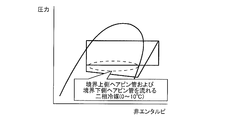
- FIG. 5 is a Mollier diagram during the heating defrost operation of the conventional air conditioner 100A.
- FIG. 6 is a temperature distribution diagram near the boundary between the upper heat exchanger 50A and the lower heat exchanger 50B during the heating defrost operation of the conventional air conditioner 100A.
- FIGS. 2 to 4 indicate a boundary line 50C between the upper heat exchanger 50A and the lower heat exchanger 50B.
- the black arrows shown in FIGS. 3 and 4 indicate the flow of the refrigerant.
- the thick solid line shown in FIG. 6 indicates the temperature at each position of the upper heat exchanger 50A during defrosting, and the thick broken line shown in FIG. 6 indicates the temperature at each position of the lower heat exchanger 50B during defrosting. Shows.
- FIG. 6 shows the temperature related to the windward side of the hairpin tube 51 (hereinafter, referred to as the boundary upper hairpin tube 51a and the boundary lower hairpin tube 51b) located at the boundary between the upper heat exchanger 50A and the lower heat exchanger 50B.
- the temperature distribution is the same on the leeward side.
- the configuration of the outdoor heat exchanger 50 shown is not limited.
- a high-temperature refrigerant is poured into the lower heat exchanger 50B from one boundary lower hairpin tube 51b, and the lower heat exchanger 50B is defrosted to re-ice (hereinafter, ice). It is called re-freezing).
- the upper heat exchanger 50A serves as an evaporator.
- the evaporation temperature of the refrigerant flowing in the evaporator is lowered, and the amount of frost formed on the heat transfer fins 52 of the evaporator is increased.
- the amount of frost is increased, when the upper heat exchanger 50A is defrosted again, there arises a problem that the heating capacity is lowered and the defrosting completion time becomes long.
- the temperature Ta1 of the lower boundary hairpin tube 51b at the time of defrosting the lower heat exchanger 50B is relatively lower than Ta2 of the first embodiment described later. Further, the temperature Tc1 at the boundary between the upper heat exchanger 50A and the lower heat exchanger 50B becomes 0° C. or lower both when the upper heat exchanger 50A is defrosted and when the lower heat exchanger 50B is defrosted, and 0° C. There is an area that does not grow. And re-freezing does not melt in that area.
- the temperature Te1 shown in FIG. 6 is the temperature of the lower boundary hairpin tube 51b when the upper heat exchanger 50A is defrosted.
- FIG. 7 shows the upper heat exchanger 50A and the lower heat exchanger 50B when the upper heat exchanger 50A of the outdoor heat exchanger 50 of the air conditioner 100 according to Embodiment 1 of the present invention is defrosted.
- It is a schematic diagram which shows the cross section near a boundary.
- FIG. 8 shows an upper heat exchanger 50A and a lower heat exchanger 50B when the lower heat exchanger 50B of the outdoor heat exchanger 50 of the air conditioner 100 according to Embodiment 1 of the present invention is defrosted.
- 3 is a schematic view showing a cross section near the boundary of FIG.
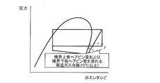
- FIG. 9 is a Mollier diagram during heating defrost operation of air conditioner 100 according to Embodiment 1 of the present invention.
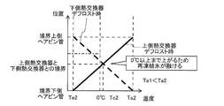
- FIG. 10 is a temperature distribution diagram near the boundary of the outdoor heat exchanger 50 during the heating defrost operation of the air conditioner 100 according to Embodiment 1 of the present invention.
- FIGS. 7 and 8 indicate a boundary line 50C between the upper heat exchanger 50A and the lower heat exchanger 50B.
- the black arrows shown in FIGS. 7 and 8 indicate the flow of the refrigerant.
- the thick solid line shown in FIG. 10 indicates the temperature at each position of the upper heat exchanger 50A during defrosting, and the thick broken line shown in FIG. 10 indicates the temperature at each position of the lower heat exchanger 50B during defrosting. Shows.
- FIG. 10 shows temperature distributions on the windward side of the upper boundary hairpin tube 51a and the lower boundary hairpin tube 51b, similar temperature distributions are also obtained on the leeward side.
- the configuration of the outdoor heat exchanger 50 shown is not limited.
- all the hairpin tubes 51 located at the lowermost stage of the upper heat exchanger 50A to be defrosted are designated as inlets of high-temperature gas refrigerant (hereinafter referred to as refrigerant inlets).
- refrigerant inlets high-temperature gas refrigerant
- all the hairpin tubes 51 located at the uppermost stage of the lower heat exchanger 50B to be defrosted are arranged so as to serve as refrigerant inlets. That is, all the hairpin tubes 51 located at the boundary between the upper heat exchanger 50A and the lower heat exchanger 50B are arranged so as to serve as the refrigerant inlet when defrosting is performed.
- the hairpin tube 51 located at the boundary is the hairpin tube 51 facing the boundary line 50C in the schematic views showing the cross section of the outdoor heat exchanger 50 shown in FIGS. 7 and 8.
- the boundary upper hairpin tube 51a located at the lowermost stage of each row and adjacent to the lower heat exchanger 50B, and in the lower heat exchanger 50B, the uppermost of each row.
- the lower boundary hairpin tube 51b located in the upper stage and adjacent to the upper heat exchanger 50A.
- the heat exchanger 50B is arranged so as to serve as a refrigerant inlet when a defrost target is set.
- two hairpin tubes 51 (boundary upper hairpin tube 51a and lower boundary hairpin tube 51b) are used as the refrigerant when defrosting. It is arranged to be the entrance.
- the number of the hairpin tubes 51 serving as the refrigerant inlets is not limited to two, and when the number of rows of the outdoor heat exchangers 50 is three, the number of the hairpin tubes 51 serving as the refrigerant inlets is three, respectively. It becomes a book.
- the high-temperature gas refrigerant flowing from the refrigerant inlet during the heating defrosting operation becomes a boundary between the upper heat exchanger 50A and the lower heat exchanger 50B as shown in FIG. Flows to the upper boundary hairpin tube 51a or the lower boundary hairpin tube 51b located at. Therefore, the temperatures of the upper boundary hairpin tube 51a, the lower boundary hairpin tube 51b, and the heat transfer fin 52 are likely to rise.
- control device 300 controls the second expansion device 60 to keep the temperature Ta2 (>Ta1) of the lower boundary hairpin tube 51b at a high temperature. Specifically, when the temperature Ta2 of the lower boundary hairpin tube 51b decreases and becomes equal to or lower than a preset temperature Ta1+ ⁇ , the opening degree of the second expansion device 60 is changed to the closing direction. Then, the temperature difference at the boundary between the upper heat exchanger 50A and the lower heat exchanger 50B is increased. By doing so, as shown in FIG. 10, the temperature Tc2 at the boundary between the upper heat exchanger 50A and the lower heat exchanger 50B is at the time of defrosting of the upper heat exchanger 50A and at the time of defrosting of the lower heat exchanger 50B.
- the temperature is higher than 0°C. Therefore, the heating defrost operation does not reach 0° C. or lower in both the upper heat exchanger 50A and the lower heat exchanger 50B, and the drainage near the boundary between the upper heat exchanger 50A and the lower heat exchanger 50B. It can suppress re-freezing of water.
- the compressor 10, the indoor heat exchanger 40, the first expansion device 30, the outdoor heat exchanger 50, and the second flow path switching device 70 are sequentially piped. It is provided with a refrigerant circuit that is connected and circulates the refrigerant. Further, the hot gas bypass pipes 80 and 88 that connect the discharge side of the compressor 10 and the second flow path switching device 70, and the upper heat exchanger 50A and the lower heat exchanger 50B alternate while performing the heating normal operation.
- the controller 300 which performs the heating defrost operation which defrosts.
- the outdoor heat exchanger 50 has a plurality of hairpin tubes 51 forming a part of the heat transfer piping.
- the upper heat exchanger 50A serves as a refrigerant inlet when all the hairpin tubes 51 located at the lowermost stage are defrosted.
- the lower heat exchanger 50B serves as a refrigerant inlet when all the hairpin tubes 51 located at the uppermost stage are defrosted.
- the pipe 51 serves as a refrigerant inlet when defrosted. Therefore, re-freezing of the drain water can be suppressed at the boundary between the upper heat exchanger 50A and the lower heat exchanger 50B, and the reduction of the heating capacity can be suppressed, so that the highly reliable air conditioner 100 is provided. can do.
- the air conditioner 100 includes the second expansion device 60 provided in the hot gas bypass pipes 80 and 88. Further, the first boundary temperature detection device 201 that directly or indirectly detects the temperature of the hairpin tube 51 located at the lowermost stage of the upper heat exchanger 50A, and the hairpin tube located at the uppermost stage of the lower heat exchanger 50B. And a second boundary temperature detection device 202 that directly or indirectly detects the temperature of 51. Then, during the heating defrost operation, the control device 300 causes the second throttle device so that both the temperature detected by the first boundary temperature detecting device 201 and the temperature detected by the second boundary temperature detecting device 202 are higher than 0°C. It controls 60.
- the upper side heat is detected based on the temperature detected by the first boundary temperature detecting device 201 and the temperature detected by the second boundary temperature detecting device 202 during the heating defrosting operation.
- the second expansion device 60 is controlled so that both the temperature of the hairpin tube 51 located at the lowermost stage of the exchanger 50A and the temperature of the hairpin tube 51 located at the uppermost stage of the lower heat exchanger 50B are higher than 0°C. .. Therefore, the heating defrost operation does not become an operation at 0° C. or less in both of the upper heat exchanger 50A and the lower heat exchanger 50B, and the vicinity of the boundary between the upper heat exchanger 50A and the lower heat exchanger 50B. This can prevent the drain water from refreezing.
- the opening of the second expansion device 60, the operating frequency of the compressor 10, and the opening of the first expansion device 30 may be changed as necessary.
- the operating frequency of the compressor 10 may be increased.
- the opening degree of the second expansion device 60 may be changed to the closing direction. In this case, since the flow rate of the refrigerant flowing through the hot gas bypass pipe 88 decreases, the heat exchange amount in the upper heat exchanger 50A or the lower heat exchanger 50B that is the object of defrosting decreases.
- the opening degree of the first expansion device 30 may be changed to the opening direction.
- Embodiment 2 the second embodiment of the present invention will be described, but the description of the same parts as those of the first embodiment will be omitted, and the same or corresponding parts as those of the first embodiment will be designated by the same reference numerals.
- FIG. 11 is a refrigerant circuit diagram of the air conditioner 100 according to Embodiment 2 of the present invention.
- the second flow path switching device 70 is configured by an integrated valve that selectively switches the flow of the refrigerant to the upper heat exchanger 50A side or the lower heat exchanger 50B side.
- the second flow path switching device 70 is composed of four electromagnetic valves 70A to 70D. Even if the second flow path switching device 70 has such a configuration, the same effect as that of the first embodiment can be obtained.
- Embodiment 3 Hereinafter, the third embodiment of the present invention will be described, but the description of the same parts as those of the first embodiment will be omitted, and the same or corresponding parts as those of the first embodiment will be designated by the same reference numerals.
- FIG. 12 is a refrigerant circuit diagram of the air conditioner 100 according to Embodiment 3 of the present invention.
- the second flow path switching device 70 is configured by an integrated valve that selectively switches the flow of the refrigerant to the upper heat exchanger 50A side or the lower heat exchanger 50B side.
- the second flow path switching device 70 is composed of two three-way valves 600 and 700. Even if the second flow path switching device 70 has such a configuration, the same effect as that of the first embodiment can be obtained.
- FIG. 13 is a refrigerant circuit diagram of the air conditioner 100 according to Embodiment 4 of the present invention.
- the second flow path switching device 70 is configured by an integrated valve that selectively switches the flow of the refrigerant to the upper heat exchanger 50A side or the lower heat exchanger 50B side.
- the second flow path switching device 70 is composed of two three-way valves 600A and 700A. Since these two three-way valves 600A and 700A are operated by differential pressure, respectively, in order to secure the differential pressure, the E port of the first flow path switching device 20, the Q port of the three-way valve 600A, and the U port of 700A are provided. A check valve 90 is provided between the two. Even if the second flow path switching device 70 has such a configuration, the same effect as that of the first embodiment can be obtained.
Abstract
空気調和機は、冷媒を圧縮して吐出する圧縮機、冷媒と室内空気とを熱交換させる室内熱交換器、冷媒を減圧する第一絞り装置、互いに流路が並列している上側熱交換器と下側熱交換器とで構成され冷媒と外気とを熱交換させる室外熱交換器、および、冷媒の流れを前記上側熱交換器側または前記下側熱交換器側に切り替える流路切替装置が順次配管で接続され、冷媒が循環する冷媒回路と、前記圧縮機の吐出側と前記流路切替装置とを連結するホットガスバイパス配管と、暖房通常運転を行いながら前記上側熱交換器および前記下側熱交換器を交互にデフロストする暖房デフロスト運転を行う制御装置と、を備え、前記室外熱交換器は伝熱配管の一部を構成する複数のヘアピン管を有し、前記上側熱交換器は、最下段に位置する全ての前記ヘアピン管が、デフロストされる際に冷媒入口となり、前記下側熱交換器は、最上段に位置する全ての前記ヘアピン管が、デフロストされる際に冷媒入口となるものである。
Description
本発明は、室外熱交換器のデフロストと室内の暖房とを同時に行う空気調和機に関するものである。
従来、室外熱交換器のデフロストと室内の暖房とを同時に行う空気調和機がある(例えば、特許文献1参照)。特許文献1では、圧縮機、四方弁、室内熱交換器、減圧装置および室外熱交換器を冷媒配管で連結した冷媒回路を有し、圧縮機の吐出側から室外熱交換器にホットガスを流すバイパス回路を設けている。室外熱交換器は、その冷媒回路を上下に2つに分けて、下側熱交換器と上側熱交換器とを構成している。
そして、制御装置により、主回路開閉機構と第二絞り装置とを開閉して、上側熱交換器をデフロストしつつ下側熱交換器で暖房した後に、下側熱交換器をデフロストしつつ上側熱交換器で暖房する、暖房デフロスト運転を行う。このように暖房デフロスト運転を行うことで、室内機の暖房能力の低下を抑制しつつ、室内の温度低下を抑えることができる。そのため、デフロストしながら室内の快適感が失われるのを防ぐことができる。
また、特許文献1では、室外熱交換器は複数の冷媒流路であるパスを有し、その複数あるパスのうちの1つである、冷房入口側配管すなわち除霜しながら暖房を継続する暖房デフロスト運転時のパス入口を、上側熱交換器と下側熱交換器との境界に配置している。
特許文献1は、暖房デフロスト運転時において、上側熱交換器をデフロストする際、上側熱交換器で融解したドレン水が室外熱交換器の伝熱フィン上を流下する。また、下側熱交換器は蒸発器となり、その熱交換器の温度が0℃以下まで低下すると、ドレン水が下側熱交換器で再氷結する。その後、下側熱交換器を除霜すると下側熱交換器で再氷結したドレン水は融けるが、上側熱交換器が蒸発器となるため、上側熱交換器と下側熱交換器との熱伝導により、上側熱交換器と下側熱交換器との境界の温度は上がりづらい。そのため、ドレン水が再氷結した氷が融けずに成長して室外熱交換器の伝熱フィンの空気流を阻害し、暖房能力の低下を招くなどの課題があった。
また、これまでのパス構成では、上側熱交換器と下側熱交換器との境界に複数あるヘアピン管のうち、暖房デフロスト運転時の高温のガス冷媒の入口配管が1本しかない。そのため、境界のその他のヘアピン管およびその周囲の伝熱フィンの温度は上昇せず、ドレン水が再氷結した氷を融かしづらいという課題があった。
本発明は、以上のような課題を解決するためになされたもので、上側熱交換器と下側熱交換器との境界でドレン水が再氷結して、暖房能力が低下するのを抑制することができる空気調和機を提供することを目的としている。
本発明に係る空気調和機は、冷媒を圧縮して吐出する圧縮機、冷媒と室内空気とを熱交換させる室内熱交換器、冷媒を減圧する第一絞り装置、互いに流路が並列している上側熱交換器と下側熱交換器とで構成され冷媒と外気とを熱交換させる室外熱交換器、および、冷媒の流れを前記上側熱交換器側または前記下側熱交換器側に切り替える流路切替装置が順次配管で接続され、冷媒が循環する冷媒回路と、前記圧縮機の吐出側と前記流路切替装置とを連結するホットガスバイパス配管と、暖房通常運転を行いながら前記上側熱交換器および前記下側熱交換器を交互にデフロストする暖房デフロスト運転を行う制御装置と、を備え、前記室外熱交換器は伝熱配管の一部を構成する複数のヘアピン管を有し、前記上側熱交換器は、最下段に位置する全ての前記ヘアピン管が、デフロストされる際に冷媒入口となり、前記下側熱交換器は、最上段に位置する全ての前記ヘアピン管が、デフロストされる際に冷媒入口となるものである。
本発明に係る空気調和機によれば、上側熱交換器の最下段および下側熱交換器の最上段に位置するヘアピン管、つまりそれらの境界に位置する全てのヘアピン管が、デフロストされる際に冷媒入口となるものである。そのため、上側熱交換器と下側熱交換器との境界でドレン水が再氷結するのを抑制でき、暖房能力が低下するのを抑制することができる。
以下、本発明の実施の形態を図面に基づいて説明する。なお、以下に説明する実施の形態によって本発明が限定されるものではない。また、以下の図面では各構成部材の大きさの関係が実際のものとは異なる場合がある。
実施の形態1.
図1は、本発明の実施の形態1に係る空気調和機100の冷媒回路図である。
本実施の形態1に係る空気調和機100は、室外機1と室内機2とを備え、室外機1と室内機2とが冷媒配管83、84および電気配線(図示せず)で接続されたセパレート形である。
図1は、本発明の実施の形態1に係る空気調和機100の冷媒回路図である。
本実施の形態1に係る空気調和機100は、室外機1と室内機2とを備え、室外機1と室内機2とが冷媒配管83、84および電気配線(図示せず)で接続されたセパレート形である。
[室外機]
室外機1は、圧縮機10と、第一流路切替装置20と、第一絞り装置30と、第二絞り装置60と、第二流路切替装置70と、室外熱交換器50と、室外ファン500と、外気温度検出装置200と、第一境界温度検出装置201と、第二境界温度検出装置202と、制御装置300と、を備えている。
室外機1は、圧縮機10と、第一流路切替装置20と、第一絞り装置30と、第二絞り装置60と、第二流路切替装置70と、室外熱交換器50と、室外ファン500と、外気温度検出装置200と、第一境界温度検出装置201と、第二境界温度検出装置202と、制御装置300と、を備えている。
[室内機]
室内機2は、室内熱交換器40と、室内ファン400と、を備えている。
室内機2は、室内熱交換器40と、室内ファン400と、を備えている。
空気調和機100は、冷媒が循環する冷媒回路を有している。冷媒回路は、圧縮機10、第一流路切替装置20、室内熱交換器40、第一絞り装置30、室外熱交換器50、および、第二流路切替装置70が冷媒配管81~85、86A~87Aおよび86B~87B、89、91で順次接続されて構成されている。この冷媒回路を循環する冷媒には様々なものを採用することが可能であり、例えば、R32またはR410Aなどである。
また、圧縮機10の吐出側と第二流路切替装置70のAポートとがホットガスバイパス配管80、88で接続されており、ホットガスバイパス配管80、88には第二絞り装置60が設けられている。
[冷媒配管、ホットガスバイパス配管]
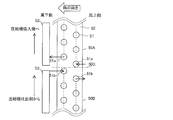
冷媒配管81は一端が圧縮機10の吐出側に接続され、他端がホットガスバイパス配管80と冷媒配管82とに分岐する。冷媒配管82は第一流路切替装置20のGポートに接続され、ホットガスバイパス配管80は第二絞り装置60に接続される。冷媒配管83は第一流路切替装置20のHポートと室内熱交換器40とを接続する。冷媒配管84は室内熱交換器40と第一絞り装置30とを接続する。冷媒配管85は一端が第一絞り装置30に接続され、他端が冷媒配管86Aと冷媒配管86Bとに分岐する。冷媒配管86Aは室外熱交換器50が有する上側熱交換器50Aに接続され、冷媒配管86Bは室外熱交換器50が有する下側熱交換器50Bに接続される。冷媒配管87Aは上側熱交換器50Aと第二流路切替装置70のB2ポートとを接続し、冷媒配管87Bは下側熱交換器50Bと第二流路切替装置70のB1ポートとを接続する。ホットガスバイパス配管88は第二絞り装置60と第二流路切替装置70のAポートとを接続する。冷媒配管89は第二流路切替装置70のCポートと第一流路切替装置20のEポートとを接続する。冷媒配管91は第一流路切替装置20のFポートと圧縮機10の吸入側とを接続する。
冷媒配管81は一端が圧縮機10の吐出側に接続され、他端がホットガスバイパス配管80と冷媒配管82とに分岐する。冷媒配管82は第一流路切替装置20のGポートに接続され、ホットガスバイパス配管80は第二絞り装置60に接続される。冷媒配管83は第一流路切替装置20のHポートと室内熱交換器40とを接続する。冷媒配管84は室内熱交換器40と第一絞り装置30とを接続する。冷媒配管85は一端が第一絞り装置30に接続され、他端が冷媒配管86Aと冷媒配管86Bとに分岐する。冷媒配管86Aは室外熱交換器50が有する上側熱交換器50Aに接続され、冷媒配管86Bは室外熱交換器50が有する下側熱交換器50Bに接続される。冷媒配管87Aは上側熱交換器50Aと第二流路切替装置70のB2ポートとを接続し、冷媒配管87Bは下側熱交換器50Bと第二流路切替装置70のB1ポートとを接続する。ホットガスバイパス配管88は第二絞り装置60と第二流路切替装置70のAポートとを接続する。冷媒配管89は第二流路切替装置70のCポートと第一流路切替装置20のEポートとを接続する。冷媒配管91は第一流路切替装置20のFポートと圧縮機10の吸入側とを接続する。
[制御装置300]
制御装置300は、例えば、専用のハードウェア、メモリに格納されるプログラムを実行するCPU(Central Processing Unit、中央処理装置、処理装置、演算装置、マイクロプロセッサ、プロセッサともいう)、またはRAMおよびROMなどのメモリから構成されている。
制御装置300は、例えば、専用のハードウェア、メモリに格納されるプログラムを実行するCPU(Central Processing Unit、中央処理装置、処理装置、演算装置、マイクロプロセッサ、プロセッサともいう)、またはRAMおよびROMなどのメモリから構成されている。
本実施の形態1に係る空気調和機100の運転動作としては、冷房運転および暖房運転の2種類がある。また、暖房運転には、上側熱交換器50Aおよび下側熱交換器50Bの両方が蒸発器として機能する暖房通常運転と、上側熱交換器50Aおよび下側熱交換器50Bのうち一方が蒸発器として機能し、もう一方が凝縮器として機能する暖房デフロスト運転との2種類がある。そして、制御装置300は、ユーザーによる選択などに応じて、それら運転動作のいずれかを行う。
圧縮機10は、制御装置300から受ける制御信号によって運転周波数を変更できるように構成されている。圧縮機10の運転周波数を変更することで、圧縮機10の出力を調整することができる。圧縮機10は種々のタイプを採用可能であり、例えば、ロータリータイプ、往復タイプ、スクロールタイプ、または、スクリュータイプなどである。
第一流路切替装置20は冷房運転と暖房運転とを切り替える装置であり、例えば四方弁であるが、二方弁と三方弁とを組み合わせて構成してもよい。暖房運転では、図1中の実線のように、圧縮機10の吐出配管である冷媒配管82と冷媒配管83とを接続するとともに、冷媒配管89と圧縮機吸入配管である冷媒配管91とを接続する。また、冷房運転では、図1中の破線のように、冷媒配管82と冷媒配管89とを接続するとともに、冷媒配管83と冷媒配管91とを接続する。
第一絞り装置30は、それに流れ込む冷媒を減圧する装置であり、例えば膨張弁である。
室内ファン400は、室内熱交換器40に併設され、室内熱交換器40に空気を供給するものである。
室外ファン500は、室外熱交換器50に併設され、室外熱交換器50に空気を供給するものである。
室外熱交換器50は、伝熱配管と複数の伝熱フィン52とヘッダ53とを有するフィンチューブ型熱交換器である。また、伝熱配管は、U字形状の複数のヘアピン管51とヘアピン管51同士を接続するUベンド管(図示せず)とで構成されている(後述する図7および図8参照)。また、室外熱交換器50は、2つに分割された上側熱交換器50Aと下側熱交換器50Bとで構成され、上側熱交換器50Aおよび下側熱交換器50Bは上下に配置されており、互いに並列に接続されている。また、上側熱交換器50Aおよび下側熱交換器50Bは、伝熱フィン52が分割されている。ただし、上側熱交換器50Aおよび下側熱交換器50Bは、伝熱フィン52が分割されていなくてもよい。また、上側熱交換器50Aおよび下側熱交換器50Bは、互いに流路が並列している。なお、冷媒の流れ方向については運転動作の説明の際に述べる。
外気温度検出装置200は、外気温度を検出するものである。また、第一境界温度検出装置201は、上側熱交換器50Aの入口配管に設けられており、上側熱交換器50Aの入口温度を検出するものである。この第一境界温度検出装置201が検出した温度と上側熱交換器50Aの最下段に位置するヘアピン管51の温度とは相関関係がある。そのため、第一境界温度検出装置201が検出した温度を補正することで、上側熱交換器50Aの最下段に位置するヘアピン管51の温度を間接的に検出することができる。また、第二境界温度検出装置202は、下側熱交換器50Bの入口配管に設けられており、下側熱交換器50Bの入口温度を検出するものである。この第二境界温度検出装置202が検出した温度と下側熱交換器50Bの最上段に位置するヘアピン管51の温度とは相関関係がある。そのため、第二境界温度検出装置202が検出した温度を補正することで、下側熱交換器50Bの最上段に位置するヘアピン管51の温度を間接的に検出することができる。外気温度検出装置200、第一境界温度検出装置201、および、第二境界温度検出装置202は、例えばサーミスタである。なお、第一境界温度検出装置201は、上側熱交換器50Aの入口配管ではなく、上側熱交換器50Aの最下段に位置するヘアピン管51に設けてもよい。そうすることで、第一境界温度検出装置201が検出した温度を補正することなく、上側熱交換器50Aの最下段に位置するヘアピン管51の温度を直接的に検出することができる。また、第二境界温度検出装置202は、下側熱交換器50Bの入口配管ではなく、下側熱交換器50Bの最上段に位置するヘアピン管51に設けてもよい。そうすることで、第二境界温度検出装置202が検出した温度を補正することなく、下側熱交換器50Bの最上段に位置するヘアピン管51の温度を直接的に検出することができる。
ホットガスバイパス配管80、88は、圧縮機10から吐出された冷媒の一部を上側熱交換器50Aおよび下側熱交換器50Bのデフロスト(除霜)に利用するために設けられている。ホットガスバイパス配管80には絞り機構として、例えば膨張弁である第二絞り装置60が接続されている。そして、第二絞り装置60で圧縮機10の吐出冷媒の一部を中圧に減圧してから、第二流路切替装置70を介して上側熱交換器50Aおよび下側熱交換器50Bのうち、デフロスト対象の方に冷媒を導く。
次に、本実施の形態1に係る空気調和機100の運転動作について説明する。
[冷房運転]
まず、冷房運転について説明する。圧縮機10は、冷媒配管91から冷媒を吸入して圧縮する。圧縮された高温高圧のガス冷媒は、圧縮機10から吐出され、冷媒配管81、冷媒配管82、第一流路切替装置20を経由し、冷媒配管89へ流れる。
まず、冷房運転について説明する。圧縮機10は、冷媒配管91から冷媒を吸入して圧縮する。圧縮された高温高圧のガス冷媒は、圧縮機10から吐出され、冷媒配管81、冷媒配管82、第一流路切替装置20を経由し、冷媒配管89へ流れる。
冷媒配管89を流れるガス冷媒は、第二流路切替装置70によって図1の実線のように分岐し、一方がポートB2から冷媒配管87Aへ流れ、もう一方がポートB1から冷媒配管87Bへ流れる。冷媒配管87Aに分岐したガス冷媒は上側熱交換器50Aに流れ、上側熱交換器50Aで室外空気と熱交換し、凝縮して高圧の液冷媒となって冷媒配管86Aに流れる。また、冷媒配管87Bに分岐したガス冷媒は下側熱交換器50Bに流れ、下側熱交換器50Bで室外空気と熱交換し、凝縮して高圧の液冷媒となって冷媒配管86Bに流れる。
ここで、制御装置300は、制御信号によって室外ファン500の回転数を調整することができる。そして、制御装置300により室外ファン500の回転数を調整することで、室外熱交換器50に輸送される空気量が変化し、室外熱交換器50における冷媒と空気の交換熱量を調整することができる。
冷媒配管86Aを流れる液冷媒と、冷媒配管86Bを流れる液冷媒とは、冷媒配管86A、86Bと冷媒配管85との合流部で合流し、冷媒配管85に流れ、第一絞り装置30によって減圧され、低温低圧の二相冷媒となって冷媒配管84へ流れる。ここで、制御装置300は、制御信号によって第一絞り装置30の開度を調整することができる。そして、このとき制御装置300により第一絞り装置30の開度を調整することで、冷媒の減圧量を調整することができる。第一絞り装置30の開度を開方向に変化させると、第一絞り装置30の出口側の冷媒圧力は上昇し、冷媒の乾き度が低下する。一方で、第一絞り装置30の開度を閉方向に変化させると、第一絞り装置30の出口側の冷媒圧力は低下し、冷媒の乾き度が上昇する。
冷媒配管84を流れる液冷媒は、室内熱交換器40に流入し、室内熱交換器40で室内空気と熱交換し、蒸発して低温低圧のガス冷媒となって冷媒配管83に流れる。
ここで、制御装置300は、制御信号によって室内ファン400の回転数を調整することができる。そして、制御装置300により室内ファン400の回転数を調整することで、室内熱交換器40に輸送される空気量が変化し、室内熱交換器40における冷媒と空気の交換熱量を調整することができる。
冷媒配管83を流れるガス冷媒は、第一流路切替装置20を経由して冷媒配管91から再び圧縮機10に流れる。
[暖房通常運転]
次に、暖房通常運転について説明する。圧縮機10は、冷媒配管91から冷媒を吸入して圧縮する。圧縮された高温高圧のガス冷媒は、圧縮機10から吐出され、冷媒配管81、冷媒配管82、第一流路切替装置20を経由し、冷媒配管83へ流れる。
次に、暖房通常運転について説明する。圧縮機10は、冷媒配管91から冷媒を吸入して圧縮する。圧縮された高温高圧のガス冷媒は、圧縮機10から吐出され、冷媒配管81、冷媒配管82、第一流路切替装置20を経由し、冷媒配管83へ流れる。
冷媒配管83から室内熱交換器40に流入したガス冷媒は、室内熱交換器40で室内空気と熱交換し、凝縮して高圧の液冷媒となって冷媒配管84に流れる。このとき、制御装置300により室内ファン400の回転数を調整することで、室内熱交換器40に輸送される空気量が変化し、室内熱交換器40における冷媒と空気の交換熱量を調整することができる。
室内熱交換器40から流出した液冷媒は、冷媒配管84を通り、第一絞り装置30によって減圧され、低温低圧の二相冷媒となって冷媒配管85へ流れる。このとき、制御装置300により第一絞り装置30の開度を調整することで、冷媒の減圧量を調整することができる。第一絞り装置30の開度を開方向に変化させると、第一絞り装置30の出口側の冷媒圧力は上昇し、冷媒の乾き度が低下する。一方で、第一絞り装置30の開度を閉方向に変化させると、第一絞り装置30の出口側の冷媒圧力は低下し、冷媒の乾き度が上昇する。
冷媒配管85を流れる二相冷媒は、冷媒配管86Aと冷媒配管86Bとに分岐する。冷媒配管86Aに分岐した二相冷媒は上側熱交換器50Aに流れ、上側熱交換器50Aで室外空気と熱交換し、蒸発して低温低圧のガス冷媒となって冷媒配管87Aに流れる。また、冷媒配管86Bに分岐した二相冷媒は下側熱交換器50Bに流れ、下側熱交換器50Bで室外空気と熱交換し、蒸発して低温低圧のガス冷媒となって冷媒配管87Bに流れる。このとき、制御装置300により室外ファン500の回転数を調整することで、室外熱交換器50に輸送される空気量が変化し、室外熱交換器50における冷媒と空気の交換熱量を調整することができる。
冷媒配管87Aを流れるガス冷媒と、冷媒配管87Bを流れるガス冷媒とは、第二流路切替装置70によって図1の実線のように合流し、Cポートから冷媒配管89へ流れる。冷媒配管89を流れるガス冷媒は、第一流路切替装置20を経由して冷媒配管91から再び圧縮機10に流れる。
なお、暖房通常運転が行われている間、第二絞り装置60の開度は開いていても全閉でもよい。第二流路切替装置70が、ポートB1とポートCとを連通し、ポートB2とポートCとを連通しているため、ホットガスバイパス配管88に冷媒が存在していても、ポートAから他のポートに冷媒が流れ出すことはない。
上記のように暖房通常運転が行われている間、室外熱交換器50に霜が付き、デフロストする必要が生じる場合がある。その際は、一旦暖房通常運転を停止し、冷房運転に切り替え、圧縮機10で圧縮された高温高圧のガス冷媒を、室外熱交換器50に流すデフロスト運転を行うことが考えられる。この場合、暖房通常運転が中断されるため、室温が低下し、室内の快適性が失われる。
[暖房デフロスト運転]
次に、暖房デフロスト運転について説明する。
暖房デフロスト運転では、暖房通常運転を継続しながら、第二流路切替装置70を動作させて上側熱交換器50Aと下側熱交換器50Bとを交互にデフロストする。
次に、暖房デフロスト運転について説明する。
暖房デフロスト運転では、暖房通常運転を継続しながら、第二流路切替装置70を動作させて上側熱交換器50Aと下側熱交換器50Bとを交互にデフロストする。
暖房通常運転が行われている間に室外熱交換器50に霜が付き、例えば、上側熱交換器50Aをデフロストする必要が生じた場合、ホットガスバイパス配管88と冷媒配管87Aとが接続され、冷媒配管87Bと冷媒配管89とが接続されるよう第二流路切替装置70を動作させる。これにより、圧縮機10から吐出された高温高圧のガス冷媒の一部がホットガスバイパス配管80に流れ込み、残りの高温高圧のガス冷媒は、冷媒配管82、第一流路切替装置20、冷媒配管83を経由して室内熱交換器40に流れる。
ホットガスバイパス配管80に流れ込んだ高温高圧のガス冷媒は第二絞り装置60によって減圧され、ホットガスバイパス配管88、第二流路切替装置70、冷媒配管87Aを経由してデフロスト対象である上側熱交換器50Aに流れ込む。上側熱交換器50Aに流れ込んだ高温のガス冷媒は、霜と熱交換しながら凝縮し、上側熱交換器50Aのデフロストを行う。
このとき、制御装置300により第二絞り装置60の開度を変更することで、デフロスト対象である上側熱交換器50Aに流れ込む冷媒量を調節して、冷媒と霜との交換熱量を調整することができる。
第二絞り装置60の開度を開方向に変化させると、第二絞り装置60の出口の冷媒量が増加して上側熱交換器50Aを流れる冷媒量が増加し、冷媒と霜との交換熱量が増加する。このとき、室内熱交換器40を流れる冷媒量は減少するため、暖房能力が下がる。
一方、第二絞り装置60の開度を閉方向に変化させると、第二絞り装置60の出口の冷媒量が減少して上側熱交換器50Aを流れる冷媒量が減少し、冷媒と霜との交換熱量が減少する。このとき、室内熱交換器40を流れる冷媒量は増加するため、暖房能力が上がる。
上側熱交換器50Aで凝縮した冷媒は、冷媒配管86Aと冷媒配管85との合流部で、室内熱交換器40で凝縮され第一絞り装置30で減圧された冷媒と合流し、冷媒配管86Bに流れる。
冷媒配管86Bに流れた冷媒は下側熱交換器50Bに流れ込み、蒸発する。その後、冷媒配管87B、第二流路切替装置70、冷媒配管89、第一流路切替装置20を経由して冷媒配管91から再び圧縮機10に流れる。
また、暖房通常運転が行われている間に室外熱交換器50に霜が付き、例えば、下側熱交換器50Bをデフロストする必要が生じた場合、ホットガスバイパス配管88と冷媒配管87Bとが接続され、冷媒配管87Aと冷媒配管89とが接続されるよう第二流路切替装置70を動作させる。これにより、圧縮機10から吐出された高温高圧のガス冷媒の一部がホットガスバイパス配管80に流れ込み、残りの高温高圧のガス冷媒は、冷媒配管82、第一流路切替装置20、冷媒配管83を経由して室内熱交換器40に流れる。
ホットガスバイパス配管80に流れ込んだ高温高圧のガス冷媒は、第二絞り装置60によって減圧され、ホットガスバイパス配管88、第二流路切替装置70、冷媒配管87Bを経由してデフロスト対象である下側熱交換器50Bに流れ込む。下側熱交換器50Bに流れ込んだ高温のガス冷媒は、霜と熱交換しながら凝縮し、下側熱交換器50Bのデフロストを行う。
下側熱交換器50Bで凝縮した冷媒は、冷媒配管86Bと冷媒配管85との合流部で、室内熱交換器40で凝縮され第一絞り装置30で減圧された冷媒と合流し、冷媒配管86Aに流れる。
冷媒配管86Aに流れた冷媒は上側熱交換器50Aに流れ込み、蒸発する。その後、冷媒配管87A、第二流路切替装置70、冷媒配管89、第一流路切替装置20を経由して冷媒配管91から再び圧縮機10に流れる。
なお、互いに並列に接続された上側熱交換器50Aおよび下側熱交換器50Bのデフロスト順序は、下側熱交換器50Bのデフロストの後、上側熱交換器50Aのデフロストを行い、その後再度下側熱交換器50Bのデフロストを行うことが望ましい。以下でその理由について説明する。
例えば、上側熱交換器50Aのデフロストの後、下側熱交換器50Bのデフロストを行う場合について考える。上側熱交換器50Aのデフロスト中、伝熱フィン52に付着した霜が融解して水滴となり、上側熱交換器50Aの伝熱フィン52面上を流下する。以下、霜が融解した水滴または水流をドレン水と称する。上側熱交換器50Aから下側熱交換器50Bに流下したドレン水の一部は、蒸発器として機能している下側熱交換器50Bで再氷結する。
その後、下側熱交換器50Bをデフロストする際は、暖房通常運転中に下側熱交換器50Bの伝熱フィン52に生じた霜と、上側熱交換器50Aから流下して再氷結したドレン水とをデフロストする必要があり、デフロスト完了に要する時間が長くなる。このとき、上側熱交換器50Aが蒸発器として機能しているため、上側熱交換器50Aに付く霜の量が多くなる。すると、次回の上側熱交換器50Aのデフロスト時に、デフロスト完了に要する時間が長くなる。
そのため、最初に下側熱交換器50Bをデフロストして暖房通常運転中に生じた霜をデフロストし、次に上側熱交換器50Aをデフロストして暖房通常運転中に生じた霜をデフロストする。最後に、上側熱交換器50Aから流下して再氷結したドレン水の一部をデフロストするために、再度下側熱交換器50Bをデフロストする。これにより、デフロスト時間を短縮することができる。
次に、上下に分割された上側熱交換器50Aと下側熱交換器50Bとで構成された室外熱交換器50を有する冷媒回路における、暖房デフロスト運転での課題について説明する。
図2は、従来の空気調和機100Aの室外熱交換器50の断面および室外ファン500を示す模式図である。図3は、従来の空気調和機100Aの室外熱交換器50の上側熱交換器50Aをデフロストしている場合における上側熱交換器50Aと下側熱交換器50Bとの境界付近の断面を示す模式図である。図4は、従来の空気調和機100Aの室外熱交換器50の下側熱交換器50Bをデフロストしている場合における上側熱交換器50Aと下側熱交換器50Bとの境界付近の断面を示す模式図である。図5は、従来の空気調和機100Aの暖房デフロスト運転時におけるモリエル線図である。図6は、従来の空気調和機100Aの暖房デフロスト運転時における上側熱交換器50Aと下側熱交換器50Bとの境界付近の温度分布図である。
なお、図2~図4に示す破線は、上側熱交換器50Aと下側熱交換器50Bとの境界線50Cを示している。また、図3および図4に示す黒矢印は、冷媒の流れを示している。また、図6に示す太い実線は、上側熱交換器50Aのデフロスト時における各位置に対する温度を、図6に示す太い破線は、下側熱交換器50Bのデフロスト時における各位置に対する温度を、それぞれ示している。また、図6は、上側熱交換器50Aと下側熱交換器50Bとの境界に位置するヘアピン管51(以下、境界上側ヘアピン管51aおよび境界下側ヘアピン管51bと称する)の風上側に関する温度分布を示しているが、風下側に関しても同様の温度分布となる。また、図2~図4の室外熱交換器50の伝熱配管の段数、伝熱フィン52の分割数、伝熱配管の列数、パス数などはあくまでも一例であり、図2~図4に示す室外熱交換器50の構成に限定されない。
従来では、図3に示すように下側熱交換器50Bの上側に配置された上側熱交換器50Aのデフロスト時、1本の境界上側ヘアピン管51aから高温の冷媒が上側熱交換器50Aに流れ込む。その後、上側熱交換器50Aの伝熱フィン52に付着した霜が融解して、その伝熱フィン52面上を流下し、下側熱交換器50Bの伝熱フィン52面上へと流れる。なお、上側熱交換器50Aをデフロストしている間、下側熱交換器50Bは蒸発器として機能する。
そして、下側熱交換器50Bの温度が0℃以下まで低下すると、上側熱交換器50Aから流下したドレン水が下側熱交換器50Bで再氷結する。
その後、図4に示すように1本の境界下側ヘアピン管51bから高温の冷媒を下側熱交換器50Bに流し込み、下側熱交換器50Bをデフロストすることで、再氷結した氷(以下、再氷結氷と称する)は融ける。ここでは、上側熱交換器50Aが蒸発器となる。そして、上側熱交換器50Aと下側熱交換器50Bとの熱伝導により、上側熱交換器50Aと下側熱交換器50Bとの境界付近の温度は上がりづらい。そのため、その境界付近の再氷結氷が融けずに成長して、室外ファン500による空気流を阻害して交換熱量が減少することで、暖房能力の低下を招く。また、蒸発器内を流れる冷媒の蒸発温度が低下して、蒸発器の伝熱フィン52への着霜量が増加する。着霜量が増加することで、再度上側熱交換器50Aをデフロストする際、暖房能力の低下およびデフロスト完了時間が長くなるなどの問題が生じる。
また、図2~図4に示すような従来の冷媒流路構成、つまりパス構成において、図3に示すように上側熱交換器50Aのデフロスト時の境界上側ヘアピン管51aおよび境界下側ヘアピン管51bを流れる冷媒は、図5に示すように二相冷媒になる。また、図4に示すように下側熱交換器50Bのデフロスト時の境界上側ヘアピン管51aおよび境界下側ヘアピン管51bを流れる冷媒は、図5に示すように二相冷媒になる。そのため、図6に示すように下側熱交換器50Bのデフロスト時の境界下側ヘアピン管51bの温度Ta1は後述する本実施の形態1のTa2に比べて比較的低くなる。また、上側熱交換器50Aと下側熱交換器50Bとの境界での温度Tc1は、上側熱交換器50Aのデフロスト時でも下側熱交換器50Bのデフロスト時でも0℃以下となり、0℃より大きくならない領域ができる。そして、その領域では再氷結氷は融けない。なお、図6に示す温度Te1は、上側熱交換器50Aのデフロスト時の境界下側ヘアピン管51bの温度である。
図7は、本発明の実施の形態1に係る空気調和機100の室外熱交換器50の上側熱交換器50Aをデフロストしている場合における上側熱交換器50Aと下側熱交換器50Bとの境界付近の断面を示す模式図である。図8は、本発明の実施の形態1に係る空気調和機100の室外熱交換器50の下側熱交換器50Bをデフロストしている場合における上側熱交換器50Aと下側熱交換器50Bとの境界付近の断面を示す模式図である。図9は、本発明の実施の形態1に係る空気調和機100の暖房デフロスト運転時におけるモリエル線図である。図10は、本発明の実施の形態1に係る空気調和機100の暖房デフロスト運転時における室外熱交換器50の境界付近の温度分布図である。
なお、図7および図8に示す破線は、上側熱交換器50Aと下側熱交換器50Bとの境界線50Cを示している。また、図7および図8に示す黒矢印は、冷媒の流れを示している。また、図10に示す太い実線は、上側熱交換器50Aのデフロスト時における各位置に対する温度を、図10に示す太い破線は、下側熱交換器50Bのデフロスト時における各位置に対する温度を、それぞれ示している。また、図10は、境界上側ヘアピン管51aおよび境界下側ヘアピン管51bの風上側に関する温度分布を示しているが、風下側に関しても同様の温度分布となる。また、図10に示す温度Te2は、上側熱交換器50Aのデフロスト時の境界下側ヘアピン管51bの温度である。また、図7および図8の室外熱交換器50の伝熱配管の段数、伝熱フィン52の分割数、伝熱配管の列数、パス数などはあくまでも一例であり、図7および図8に示す室外熱交換器50の構成に限定されない。
以下、本実施の形態1に係る空気調和機100の室外熱交換器50のパス構成について説明する。
図7に示すように、暖房デフロスト運転時において、デフロスト対象である上側熱交換器50Aの最下段に位置する全てのヘアピン管51を、高温のガス冷媒の入口(以下、冷媒入口と称する)となるように配置する。同様に、図8に示すように、暖房デフロスト運転時において、デフロスト対象である下側熱交換器50Bの最上段に位置する全てのヘアピン管51を、冷媒入口となるように配置する。つまり、上側熱交換器50Aと下側熱交換器50Bとの境界に位置する全てのヘアピン管51が、デフロスト対象時に冷媒入口となるように配置されている。
ここで、境界に位置するヘアピン管51とは、図7および図8に示す室外熱交換器50の断面を示す模式図において、境界線50Cに対向するヘアピン管51である。具体的には、上側熱交換器50Aでは、各列の最下段に位置し、下側熱交換器50Bと隣接する境界上側ヘアピン管51aであり、下側熱交換器50Bでは、各列の最上段に位置し、上側熱交換器50Aと隣接する境界下側ヘアピン管51bである。
このように、本実施の形態1では、上側熱交換器50Aと下側熱交換器50Bとの境界に位置するヘアピン管51のうち1本だけでなく全てを、上側熱交換器50Aまたは下側熱交換器50Bがデフロスト対象時に冷媒入口となるように配置する。なお、本実施の形態1では、上側熱交換器50Aおよび下側熱交換器50Bにおいて、それぞれ2本のヘアピン管51(境界上側ヘアピン管51aおよび境界下側ヘアピン管51b)が、デフロスト対象時に冷媒入口となるように配置されている。ただし、上記の冷媒入口となるヘアピン管51の数はそれぞれ2本に限定されず、例えば室外熱交換器50の列数が3の場合、上記の冷媒入口となるヘアピン管51の数はそれぞれ3本になる。
図7および図8に示すパス構成とすることで、図9に示すように暖房デフロスト運転時の冷媒入口から流れる高温のガス冷媒が、上側熱交換器50Aと下側熱交換器50Bとの境界に位置する境界上側ヘアピン管51aまたは境界下側ヘアピン管51bに流れる。そのため、境界上側ヘアピン管51a、境界下側ヘアピン管51b、および、伝熱フィン52の温度が上がりやすくなる。
また、制御装置300は第二絞り装置60を制御し、境界下側ヘアピン管51bの温度Ta2(>Ta1)を高温に保つようにする。具体的には、境界下側ヘアピン管51bの温度Ta2の温度が下がってきて、あらかじめ設定された温度Ta1+α以下となったら、第二絞り装置60の開度を閉方向に変化させる。そして、上側熱交換器50Aと下側熱交換器50Bとの境界での温度差を大きくする。そうすることで、図10に示すように上側熱交換器50Aと下側熱交換器50Bとの境界での温度Tc2が、上側熱交換器50Aのデフロスト時および下側熱交換器50Bのデフロスト時のいずれでも0℃より大きくなる。そのため、暖房デフロスト運転が、上側熱交換器50Aおよび下側熱交換器50Bのいずれでも0℃以下となる運転にならず、上側熱交換器50Aと下側熱交換器50Bとの境界付近でドレン水が再氷結するのを抑制できる。
以上、本実施の形態1に係る空気調和機100は、圧縮機10、室内熱交換器40、第一絞り装置30、室外熱交換器50、および、第二流路切替装置70が順次配管で接続され、冷媒が循環する冷媒回路を備えている。また、圧縮機10の吐出側と第二流路切替装置70とを連結するホットガスバイパス配管80、88と、暖房通常運転を行いながら上側熱交換器50Aおよび下側熱交換器50Bを交互にデフロストする暖房デフロスト運転を行う制御装置300と、を備えている。また、室外熱交換器50は伝熱配管の一部を構成する複数のヘアピン管51を有している。そして、上側熱交換器50Aは、最下段に位置する全てのヘアピン管51が、デフロストされる際に冷媒入口となるものである。さらに、下側熱交換器50Bは、最上段に位置する全てのヘアピン管51が、デフロストされる際に冷媒入口となるものである。
本実施の形態1に係る空気調和機100によれば、上側熱交換器50Aの最下段および下側熱交換器50Bの最上段に位置するヘアピン管51、つまりそれらの境界に位置する全てのヘアピン管51が、デフロストされる際に冷媒入口となるものである。そのため、上側熱交換器50Aと下側熱交換器50Bとの境界でドレン水が再氷結するのを抑制でき、暖房能力が低下するのを抑制できるため、信頼性の高い空気調和機100を提供することができる。
また、本実施の形態1に係る空気調和機100は、ホットガスバイパス配管80、88に設けられた第二絞り装置60を備えている。また、上側熱交換器50Aの最下段に位置するヘアピン管51の温度を直接的または間接的に検出する第一境界温度検出装置201と、下側熱交換器50Bの最上段に位置するヘアピン管51の温度を直接的または間接的に検出する第二境界温度検出装置202と、を備えている。そして、制御装置300は、暖房デフロスト運転時において、第一境界温度検出装置201が検出した温度および第二境界温度検出装置202が検出した温度のいずれでも0℃より大きくなるように第二絞り装置60を制御するものである。
本実施の形態1に係る空気調和機100によれば、暖房デフロスト運転時において、第一境界温度検出装置201が検出した温度および第二境界温度検出装置202が検出した温度に基づいて、上側熱交換器50Aの最下段に位置するヘアピン管51の温度および下側熱交換器50Bの最上段に位置するヘアピン管51の温度のいずれでも0℃より大きくなるように第二絞り装置60を制御する。そのため、暖房デフロスト運転が、上側熱交換器50Aおよび下側熱交換器50Bのいずれでも0℃以下となるような運転にならず、上側熱交換器50Aと下側熱交換器50Bとの境界付近でドレン水が再氷結するのを抑制できる。
なお、暖房デフロスト運転時は、必要に応じて第二絞り装置60の開度、圧縮機10の運転周波数、および、第一絞り装置30の開度を変更してもよい。例えば、暖房デフロスト運転時に室内熱交換器40の交換熱量を増加させたい場合、圧縮機10の運転周波数を増加させてもよい。また、室内熱交換器40の交換熱量を増加させたい場合、第二絞り装置60の開度を閉方向に変更してもよい。この場合は、ホットガスバイパス配管88を流れる冷媒流量が減少するため、デフロスト対象である上側熱交換器50Aまたは下側熱交換器50Bにおける交換熱量が減少する。さらに、圧縮機10から吐出される冷媒の温度を低下させたい場合は、第一絞り装置30の開度を開方向に変更してもよい。
実施の形態2.
以下、本発明の実施の形態2について説明するが、実施の形態1と重複するものについては説明を省略し、実施の形態1と同じ部分または相当する部分には同じ符号を付す。
以下、本発明の実施の形態2について説明するが、実施の形態1と重複するものについては説明を省略し、実施の形態1と同じ部分または相当する部分には同じ符号を付す。
図11は、本発明の実施の形態2に係る空気調和機100の冷媒回路図である。
実施の形態1では、第二流路切替装置70が冷媒の流れを上側熱交換器50A側または下側熱交換器50B側に選択的に切り替える一体型の弁で構成されていた。しかし、本実施の形態2では、図11に示すように、第二流路切替装置70が4つの電磁弁70A~70Dで構成されている。第二流路切替装置70がこのような構成であっても、実施の形態1と同様の効果を得ることができる。
実施の形態1では、第二流路切替装置70が冷媒の流れを上側熱交換器50A側または下側熱交換器50B側に選択的に切り替える一体型の弁で構成されていた。しかし、本実施の形態2では、図11に示すように、第二流路切替装置70が4つの電磁弁70A~70Dで構成されている。第二流路切替装置70がこのような構成であっても、実施の形態1と同様の効果を得ることができる。
実施の形態3.
以下、本発明の実施の形態3について説明するが、実施の形態1と重複するものについては説明を省略し、実施の形態1と同じ部分または相当する部分には同じ符号を付す。
以下、本発明の実施の形態3について説明するが、実施の形態1と重複するものについては説明を省略し、実施の形態1と同じ部分または相当する部分には同じ符号を付す。
図12は、本発明の実施の形態3に係る空気調和機100の冷媒回路図である。
実施の形態1では、第二流路切替装置70が冷媒の流れを上側熱交換器50A側または下側熱交換器50B側に選択的に切り替える一体型の弁で構成されていた。しかし、本実施の形態3では、図12に示すように、第二流路切替装置70が2つの三方弁600、700で構成されている。第二流路切替装置70がこのような構成であっても、実施の形態1と同様の効果を得ることができる。
実施の形態1では、第二流路切替装置70が冷媒の流れを上側熱交換器50A側または下側熱交換器50B側に選択的に切り替える一体型の弁で構成されていた。しかし、本実施の形態3では、図12に示すように、第二流路切替装置70が2つの三方弁600、700で構成されている。第二流路切替装置70がこのような構成であっても、実施の形態1と同様の効果を得ることができる。
実施の形態4.
以下、本発明の実施の形態4について説明するが、実施の形態1と重複するものについては説明を省略し、実施の形態1と同じ部分または相当する部分には同じ符号を付す。
以下、本発明の実施の形態4について説明するが、実施の形態1と重複するものについては説明を省略し、実施の形態1と同じ部分または相当する部分には同じ符号を付す。
図13は、本発明の実施の形態4に係る空気調和機100の冷媒回路図である。
実施の形態1では、第二流路切替装置70が冷媒の流れを上側熱交換器50A側または下側熱交換器50B側に選択的に切り替える一体型の弁で構成されていた。しかし、本実施の形態4では、図13に示すように、第二流路切替装置70が2つの三方弁600A、700Aで構成されている。この2つの三方弁600A、700Aは、それぞれ差圧で動作する弁であるため、差圧を確保するために第一流路切替装置20のEポートと三方弁600AのQポートおよび700AのUポートとの間に逆止弁90が設けられている。第二流路切替装置70がこのような構成であっても、実施の形態1と同様の効果を得ることができる。
実施の形態1では、第二流路切替装置70が冷媒の流れを上側熱交換器50A側または下側熱交換器50B側に選択的に切り替える一体型の弁で構成されていた。しかし、本実施の形態4では、図13に示すように、第二流路切替装置70が2つの三方弁600A、700Aで構成されている。この2つの三方弁600A、700Aは、それぞれ差圧で動作する弁であるため、差圧を確保するために第一流路切替装置20のEポートと三方弁600AのQポートおよび700AのUポートとの間に逆止弁90が設けられている。第二流路切替装置70がこのような構成であっても、実施の形態1と同様の効果を得ることができる。
1 室外機、2 室内機、10 圧縮機、20 第一流路切替装置、30 第一絞り装置、40 室内熱交換器、50 室外熱交換器、50A 上側熱交換器、50B 下側熱交換器、50C 境界線、51 ヘアピン管、51a 境界上側ヘアピン管、51b 境界下側ヘアピン管、52 伝熱フィン、53 ヘッダ、60 第二絞り装置、70 第二流路切替装置、70A~70D 電磁弁、80 ホットガスバイパス配管、81~85 冷媒配管、86A 冷媒配管、86B 冷媒配管、87A 冷媒配管、87B 冷媒配管、88 ホットガスバイパス配管、89 冷媒配管、90 逆止弁、91 冷媒配管、100 空気調和機、100A 空気調和機、200 外気温度検出装置、201 第一境界温度検出装置、202 第二境界温度検出装置、300 制御装置、400 室内ファン、500 室外ファン、600 三方弁、600A 三方弁、700 三方弁、700A 三方弁。
Claims (2)
- 冷媒を圧縮して吐出する圧縮機、冷媒と室内空気とを熱交換させる室内熱交換器、冷媒を減圧する第一絞り装置、互いに流路が並列している上側熱交換器と下側熱交換器とで構成され冷媒と外気とを熱交換させる室外熱交換器、および、冷媒の流れを前記上側熱交換器側または前記下側熱交換器側に切り替える流路切替装置が順次配管で接続され、冷媒が循環する冷媒回路と、
前記圧縮機の吐出側と前記流路切替装置とを連結するホットガスバイパス配管と、
暖房通常運転を行いながら前記上側熱交換器および前記下側熱交換器を交互にデフロストする暖房デフロスト運転を行う制御装置と、を備え、
前記室外熱交換器は伝熱配管の一部を構成する複数のヘアピン管を有し、
前記上側熱交換器は、
最下段に位置する全ての前記ヘアピン管が、デフロストされる際に冷媒入口となり、
前記下側熱交換器は、
最上段に位置する全ての前記ヘアピン管が、デフロストされる際に冷媒入口となる
空気調和機。 - 前記ホットガスバイパス配管に設けられた第二絞り装置と、
前記上側熱交換器の最下段に位置する前記ヘアピン管の温度を直接的または間接的に検出する第一境界温度検出装置と、
前記下側熱交換器の最上段に位置する前記ヘアピン管の温度を直接的または間接的に検出する第二境界温度検出装置と、を備え、
前記制御装置は、
暖房デフロスト運転時において、前記第一境界温度検出装置が検出した温度および前記第二境界温度検出装置が検出した温度に基づいて、前記上側熱交換器の最下段に位置する前記ヘアピン管の温度および前記下側熱交換器の最上段に位置する前記ヘアピン管の温度のいずれでも0℃より大きくなるように前記第二絞り装置を制御するものである
請求項1に記載の空気調和機。
Priority Applications (5)
| Application Number | Priority Date | Filing Date | Title |
|---|---|---|---|
| JP2020558709A JP6964803B2 (ja) | 2018-12-04 | 2018-12-04 | 空気調和機 |
| EP18942549.9A EP3892928A4 (en) | 2018-12-04 | 2018-12-04 | AIR CONDITIONER |
| CN201880099720.4A CN113167486B (zh) | 2018-12-04 | 2018-12-04 | 空调机 |
| PCT/JP2018/044519 WO2020115812A1 (ja) | 2018-12-04 | 2018-12-04 | 空気調和機 |
| US17/278,939 US20220049869A1 (en) | 2018-12-04 | 2018-12-04 | Air-conditioning apparatus |
Applications Claiming Priority (1)
| Application Number | Priority Date | Filing Date | Title |
|---|---|---|---|
| PCT/JP2018/044519 WO2020115812A1 (ja) | 2018-12-04 | 2018-12-04 | 空気調和機 |
Publications (1)
| Publication Number | Publication Date |
|---|---|
| WO2020115812A1 true WO2020115812A1 (ja) | 2020-06-11 |
Family
ID=70975423
Family Applications (1)
| Application Number | Title | Priority Date | Filing Date |
|---|---|---|---|
| PCT/JP2018/044519 WO2020115812A1 (ja) | 2018-12-04 | 2018-12-04 | 空気調和機 |
Country Status (5)
| Country | Link |
|---|---|
| US (1) | US20220049869A1 (ja) |
| EP (1) | EP3892928A4 (ja) |
| JP (1) | JP6964803B2 (ja) |
| CN (1) | CN113167486B (ja) |
| WO (1) | WO2020115812A1 (ja) |
Cited By (1)
| Publication number | Priority date | Publication date | Assignee | Title |
|---|---|---|---|---|
| CN111637593A (zh) * | 2020-05-25 | 2020-09-08 | 宁波奥克斯电气股份有限公司 | 一种能延缓结霜的空调器及其控制方法 |
Citations (4)
| Publication number | Priority date | Publication date | Assignee | Title |
|---|---|---|---|---|
| JP2008064381A (ja) | 2006-09-07 | 2008-03-21 | Hitachi Appliances Inc | 空気調和機 |
| JP2010139097A (ja) * | 2008-12-09 | 2010-06-24 | Mitsubishi Electric Corp | 空気調和機 |
| WO2016113850A1 (ja) * | 2015-01-13 | 2016-07-21 | 三菱電機株式会社 | 空気調和装置 |
| WO2016117131A1 (ja) * | 2015-01-23 | 2016-07-28 | 三菱電機株式会社 | 空気調和装置の室外機 |
Family Cites Families (13)
| Publication number | Priority date | Publication date | Assignee | Title |
|---|---|---|---|---|
| US5219023A (en) * | 1992-03-09 | 1993-06-15 | General Motors Corporation | Three row condenser with high efficiency flow path |
| US5315836A (en) * | 1993-01-15 | 1994-05-31 | Mccormack Manufacturing Co., Inc. | Air cooling unit having a hot gas defrost circuit |
| JP4760542B2 (ja) * | 2006-05-31 | 2011-08-31 | ダイキン工業株式会社 | 熱交換器 |
| JP2009264605A (ja) * | 2008-04-22 | 2009-11-12 | Daikin Ind Ltd | 冷凍装置 |
| KR20100081621A (ko) * | 2009-01-06 | 2010-07-15 | 엘지전자 주식회사 | 공기조화기 및 공기조화기의 제상운전방법 |
| CN102338592B (zh) * | 2010-07-27 | 2013-04-24 | 约克广州空调冷冻设备有限公司 | 用于空调热泵的热交换器 |
| JP6085255B2 (ja) * | 2012-01-24 | 2017-02-22 | 三菱電機株式会社 | 空気調和装置 |
| US10001317B2 (en) * | 2012-11-29 | 2018-06-19 | Mitsubishi Electric Corporation | Air-conditioning apparatus providing defrosting without suspending a heating operation |
| CN105723168B (zh) * | 2013-10-24 | 2018-05-11 | 三菱电机株式会社 | 空调装置 |
| US20160123645A1 (en) * | 2014-10-29 | 2016-05-05 | Lg Electronics Inc. | Air conditioner and method of controlling the same |
| US10415860B2 (en) * | 2015-09-09 | 2019-09-17 | Mitsubishi Electric Corporation | Air-conditioning apparatus |
| JP6576552B2 (ja) * | 2016-05-16 | 2019-09-18 | 三菱電機株式会社 | 空気調和装置 |
| KR102447943B1 (ko) * | 2018-02-05 | 2022-09-28 | 엘지전자 주식회사 | 공기조화기 |
-
2018
- 2018-12-04 WO PCT/JP2018/044519 patent/WO2020115812A1/ja unknown
- 2018-12-04 US US17/278,939 patent/US20220049869A1/en active Pending
- 2018-12-04 JP JP2020558709A patent/JP6964803B2/ja active Active
- 2018-12-04 CN CN201880099720.4A patent/CN113167486B/zh active Active
- 2018-12-04 EP EP18942549.9A patent/EP3892928A4/en active Pending
Patent Citations (4)
| Publication number | Priority date | Publication date | Assignee | Title |
|---|---|---|---|---|
| JP2008064381A (ja) | 2006-09-07 | 2008-03-21 | Hitachi Appliances Inc | 空気調和機 |
| JP2010139097A (ja) * | 2008-12-09 | 2010-06-24 | Mitsubishi Electric Corp | 空気調和機 |
| WO2016113850A1 (ja) * | 2015-01-13 | 2016-07-21 | 三菱電機株式会社 | 空気調和装置 |
| WO2016117131A1 (ja) * | 2015-01-23 | 2016-07-28 | 三菱電機株式会社 | 空気調和装置の室外機 |
Non-Patent Citations (1)
| Title |
|---|
| See also references of EP3892928A4 |
Cited By (1)
| Publication number | Priority date | Publication date | Assignee | Title |
|---|---|---|---|---|
| CN111637593A (zh) * | 2020-05-25 | 2020-09-08 | 宁波奥克斯电气股份有限公司 | 一种能延缓结霜的空调器及其控制方法 |
Also Published As
| Publication number | Publication date |
|---|---|
| EP3892928A1 (en) | 2021-10-13 |
| JP6964803B2 (ja) | 2021-11-10 |
| EP3892928A4 (en) | 2021-12-15 |
| CN113167486A (zh) | 2021-07-23 |
| CN113167486B (zh) | 2022-10-14 |
| US20220049869A1 (en) | 2022-02-17 |
| JPWO2020115812A1 (ja) | 2021-09-02 |
Similar Documents
| Publication | Publication Date | Title |
|---|---|---|
| EP3477222B1 (en) | Refrigeration cycle device | |
| JP6685409B2 (ja) | 空気調和装置 | |
| US8424333B2 (en) | Air conditioner | |
| EP1521046A2 (en) | Refrigerant circuit and heat pump type hot water supply apparatus | |
| JP6678332B2 (ja) | 空気調和機の室外ユニットおよび制御方法 | |
| JP4874223B2 (ja) | 空気調和機 | |
| WO2013001976A1 (ja) | 空気調和装置 | |
| EP2211127A1 (en) | Heat pump type air conditioner | |
| JP2008256304A (ja) | 冷凍装置 | |
| KR20100096182A (ko) | 냉동 장치 | |
| JP6285172B2 (ja) | 空気調和機の室外機 | |
| WO2005024313A1 (ja) | 冷凍装置 | |
| JP5734205B2 (ja) | 空気調和装置 | |
| JP2010203673A (ja) | 空気調和装置 | |
| JP7042906B2 (ja) | 空気調和機 | |
| JP2009243842A (ja) | マルチ型空気調和機および室外機の運転方法 | |
| WO2020115812A1 (ja) | 空気調和機 | |
| WO2021053820A1 (ja) | 空気調和機 | |
| JP6664503B2 (ja) | 空気調和装置 | |
| KR101692243B1 (ko) | 캐스캐이드 사이클을 이용한 히트 펌프 | |
| JP2013204952A (ja) | 冷凍サイクル装置 | |
| JP7098064B2 (ja) | 空気調和機 | |
| WO2021014520A1 (ja) | 空気調和装置 | |
| CN117355721A (zh) | 热交换器、具备热交换器的空调装置的室外机、以及具备空调装置的室外机的空调装置 | |
| JP2005233451A (ja) | 空気調和装置 |
Legal Events
| Date | Code | Title | Description |
|---|---|---|---|
| 121 | Ep: the epo has been informed by wipo that ep was designated in this application |
Ref document number: 18942549 Country of ref document: EP Kind code of ref document: A1 |
|
| ENP | Entry into the national phase |
Ref document number: 2020558709 Country of ref document: JP Kind code of ref document: A |
|
| NENP | Non-entry into the national phase |
Ref country code: DE |
|
| ENP | Entry into the national phase |
Ref document number: 2018942549 Country of ref document: EP Effective date: 20210705 |