WO2020115812A1 - Climatiseur - Google Patents
Climatiseur Download PDFInfo
- Publication number
- WO2020115812A1 WO2020115812A1 PCT/JP2018/044519 JP2018044519W WO2020115812A1 WO 2020115812 A1 WO2020115812 A1 WO 2020115812A1 JP 2018044519 W JP2018044519 W JP 2018044519W WO 2020115812 A1 WO2020115812 A1 WO 2020115812A1
- Authority
- WO
- WIPO (PCT)
- Prior art keywords
- heat exchanger
- refrigerant
- temperature
- boundary
- upper heat
- Prior art date
Links
Images


Classifications
-
- F—MECHANICAL ENGINEERING; LIGHTING; HEATING; WEAPONS; BLASTING
- F24—HEATING; RANGES; VENTILATING
- F24F—AIR-CONDITIONING; AIR-HUMIDIFICATION; VENTILATION; USE OF AIR CURRENTS FOR SCREENING
- F24F11/00—Control or safety arrangements
- F24F11/30—Control or safety arrangements for purposes related to the operation of the system, e.g. for safety or monitoring
- F24F11/41—Defrosting; Preventing freezing
- F24F11/42—Defrosting; Preventing freezing of outdoor units
-
- F—MECHANICAL ENGINEERING; LIGHTING; HEATING; WEAPONS; BLASTING
- F24—HEATING; RANGES; VENTILATING
- F24F—AIR-CONDITIONING; AIR-HUMIDIFICATION; VENTILATION; USE OF AIR CURRENTS FOR SCREENING
- F24F1/00—Room units for air-conditioning, e.g. separate or self-contained units or units receiving primary air from a central station
- F24F1/06—Separate outdoor units, e.g. outdoor unit to be linked to a separate room comprising a compressor and a heat exchanger
- F24F1/14—Heat exchangers specially adapted for separate outdoor units
- F24F1/16—Arrangement or mounting thereof
-
- F—MECHANICAL ENGINEERING; LIGHTING; HEATING; WEAPONS; BLASTING
- F24—HEATING; RANGES; VENTILATING
- F24F—AIR-CONDITIONING; AIR-HUMIDIFICATION; VENTILATION; USE OF AIR CURRENTS FOR SCREENING
- F24F11/00—Control or safety arrangements
- F24F11/30—Control or safety arrangements for purposes related to the operation of the system, e.g. for safety or monitoring
- F24F11/41—Defrosting; Preventing freezing
-
- F—MECHANICAL ENGINEERING; LIGHTING; HEATING; WEAPONS; BLASTING
- F25—REFRIGERATION OR COOLING; COMBINED HEATING AND REFRIGERATION SYSTEMS; HEAT PUMP SYSTEMS; MANUFACTURE OR STORAGE OF ICE; LIQUEFACTION SOLIDIFICATION OF GASES
- F25B—REFRIGERATION MACHINES, PLANTS OR SYSTEMS; COMBINED HEATING AND REFRIGERATION SYSTEMS; HEAT PUMP SYSTEMS
- F25B13/00—Compression machines, plants or systems, with reversible cycle
-
- F—MECHANICAL ENGINEERING; LIGHTING; HEATING; WEAPONS; BLASTING
- F25—REFRIGERATION OR COOLING; COMBINED HEATING AND REFRIGERATION SYSTEMS; HEAT PUMP SYSTEMS; MANUFACTURE OR STORAGE OF ICE; LIQUEFACTION SOLIDIFICATION OF GASES
- F25B—REFRIGERATION MACHINES, PLANTS OR SYSTEMS; COMBINED HEATING AND REFRIGERATION SYSTEMS; HEAT PUMP SYSTEMS
- F25B39/00—Evaporators; Condensers
- F25B39/02—Evaporators
-
- F—MECHANICAL ENGINEERING; LIGHTING; HEATING; WEAPONS; BLASTING
- F25—REFRIGERATION OR COOLING; COMBINED HEATING AND REFRIGERATION SYSTEMS; HEAT PUMP SYSTEMS; MANUFACTURE OR STORAGE OF ICE; LIQUEFACTION SOLIDIFICATION OF GASES
- F25B—REFRIGERATION MACHINES, PLANTS OR SYSTEMS; COMBINED HEATING AND REFRIGERATION SYSTEMS; HEAT PUMP SYSTEMS
- F25B41/00—Fluid-circulation arrangements
- F25B41/20—Disposition of valves, e.g. of on-off valves or flow control valves
-
- F—MECHANICAL ENGINEERING; LIGHTING; HEATING; WEAPONS; BLASTING
- F25—REFRIGERATION OR COOLING; COMBINED HEATING AND REFRIGERATION SYSTEMS; HEAT PUMP SYSTEMS; MANUFACTURE OR STORAGE OF ICE; LIQUEFACTION SOLIDIFICATION OF GASES
- F25B—REFRIGERATION MACHINES, PLANTS OR SYSTEMS; COMBINED HEATING AND REFRIGERATION SYSTEMS; HEAT PUMP SYSTEMS
- F25B47/00—Arrangements for preventing or removing deposits or corrosion, not provided for in another subclass
- F25B47/02—Defrosting cycles
- F25B47/022—Defrosting cycles hot gas defrosting
-
- F—MECHANICAL ENGINEERING; LIGHTING; HEATING; WEAPONS; BLASTING
- F25—REFRIGERATION OR COOLING; COMBINED HEATING AND REFRIGERATION SYSTEMS; HEAT PUMP SYSTEMS; MANUFACTURE OR STORAGE OF ICE; LIQUEFACTION SOLIDIFICATION OF GASES
- F25B—REFRIGERATION MACHINES, PLANTS OR SYSTEMS; COMBINED HEATING AND REFRIGERATION SYSTEMS; HEAT PUMP SYSTEMS
- F25B2313/00—Compression machines, plants or systems with reversible cycle not otherwise provided for
- F25B2313/025—Compression machines, plants or systems with reversible cycle not otherwise provided for using multiple outdoor units
- F25B2313/0251—Compression machines, plants or systems with reversible cycle not otherwise provided for using multiple outdoor units being defrosted alternately
-
- F—MECHANICAL ENGINEERING; LIGHTING; HEATING; WEAPONS; BLASTING
- F25—REFRIGERATION OR COOLING; COMBINED HEATING AND REFRIGERATION SYSTEMS; HEAT PUMP SYSTEMS; MANUFACTURE OR STORAGE OF ICE; LIQUEFACTION SOLIDIFICATION OF GASES
- F25B—REFRIGERATION MACHINES, PLANTS OR SYSTEMS; COMBINED HEATING AND REFRIGERATION SYSTEMS; HEAT PUMP SYSTEMS
- F25B2313/00—Compression machines, plants or systems with reversible cycle not otherwise provided for
- F25B2313/025—Compression machines, plants or systems with reversible cycle not otherwise provided for using multiple outdoor units
- F25B2313/0253—Compression machines, plants or systems with reversible cycle not otherwise provided for using multiple outdoor units in parallel arrangements
-
- F—MECHANICAL ENGINEERING; LIGHTING; HEATING; WEAPONS; BLASTING
- F25—REFRIGERATION OR COOLING; COMBINED HEATING AND REFRIGERATION SYSTEMS; HEAT PUMP SYSTEMS; MANUFACTURE OR STORAGE OF ICE; LIQUEFACTION SOLIDIFICATION OF GASES
- F25B—REFRIGERATION MACHINES, PLANTS OR SYSTEMS; COMBINED HEATING AND REFRIGERATION SYSTEMS; HEAT PUMP SYSTEMS
- F25B2313/00—Compression machines, plants or systems with reversible cycle not otherwise provided for
- F25B2313/031—Sensor arrangements
- F25B2313/0315—Temperature sensors near the outdoor heat exchanger
-
- F—MECHANICAL ENGINEERING; LIGHTING; HEATING; WEAPONS; BLASTING
- F25—REFRIGERATION OR COOLING; COMBINED HEATING AND REFRIGERATION SYSTEMS; HEAT PUMP SYSTEMS; MANUFACTURE OR STORAGE OF ICE; LIQUEFACTION SOLIDIFICATION OF GASES
- F25B—REFRIGERATION MACHINES, PLANTS OR SYSTEMS; COMBINED HEATING AND REFRIGERATION SYSTEMS; HEAT PUMP SYSTEMS
- F25B2700/00—Sensing or detecting of parameters; Sensors therefor
- F25B2700/21—Temperatures
- F25B2700/2106—Temperatures of fresh outdoor air
-
- F—MECHANICAL ENGINEERING; LIGHTING; HEATING; WEAPONS; BLASTING
- F25—REFRIGERATION OR COOLING; COMBINED HEATING AND REFRIGERATION SYSTEMS; HEAT PUMP SYSTEMS; MANUFACTURE OR STORAGE OF ICE; LIQUEFACTION SOLIDIFICATION OF GASES
- F25B—REFRIGERATION MACHINES, PLANTS OR SYSTEMS; COMBINED HEATING AND REFRIGERATION SYSTEMS; HEAT PUMP SYSTEMS
- F25B2700/00—Sensing or detecting of parameters; Sensors therefor
- F25B2700/21—Temperatures
- F25B2700/2117—Temperatures of an evaporator
- F25B2700/21174—Temperatures of an evaporator of the refrigerant at the inlet of the evaporator
Definitions
- the present invention relates to an air conditioner that simultaneously performs defrosting of an outdoor heat exchanger and indoor heating.
- Patent Document 1 there is an air conditioner that simultaneously performs defrosting of the outdoor heat exchanger and heating of the room (see, for example, Patent Document 1).
- a compressor, a four-way valve, an indoor heat exchanger, a decompression device, and an outdoor heat exchanger are provided with a refrigerant circuit, and a hot gas flows from the discharge side of the compressor to the outdoor heat exchanger.
- a bypass circuit is provided.
- the outdoor heat exchanger has a lower heat exchanger and an upper heat exchanger which are divided into upper and lower refrigerant circuits.
- the control device opens and closes the main circuit opening/closing mechanism and the second expansion device to heat the upper heat exchanger while defrosting the lower heat exchanger, and then defrosting the lower heat exchanger to heat the upper heat exchanger.
- the outdoor heat exchanger has a plurality of paths that are refrigerant passages, and one of the plurality of paths is a cooling inlet side pipe, that is, heating that continues heating while defrosting.
- the path inlet at the time of defrost operation is arranged at the boundary between the upper heat exchanger and the lower heat exchanger.
- Patent Document 1 when the upper heat exchanger is defrosted during heating defrosting, drain water melted in the upper heat exchanger flows down on the heat transfer fins of the outdoor heat exchanger. Further, the lower heat exchanger becomes an evaporator, and when the temperature of the heat exchanger drops to 0° C. or lower, drain water is re-frozen in the lower heat exchanger. After that, when the lower heat exchanger is defrosted, the drain water re-iced in the lower heat exchanger melts, but the upper heat exchanger becomes an evaporator, so the heat of the upper heat exchanger and the lower heat exchanger is Due to conduction, the temperature at the boundary between the upper heat exchanger and the lower heat exchanger is hard to rise. Therefore, there is a problem that the ice re-freezing the drain water grows without melting and inhibits the air flow of the heat transfer fins of the outdoor heat exchanger, resulting in a decrease in heating capacity.
- the present invention has been made to solve the above problems, and suppresses a decrease in heating capacity due to re-freezing of drain water at the boundary between the upper heat exchanger and the lower heat exchanger. It is intended to provide an air conditioner that can do the work.
- the air conditioner according to the present invention includes a compressor for compressing and discharging a refrigerant, an indoor heat exchanger for exchanging heat between the refrigerant and room air, a first throttle device for decompressing the refrigerant, and flow paths arranged in parallel with each other.
- An outdoor heat exchanger configured by an upper heat exchanger and a lower heat exchanger for exchanging heat between a refrigerant and the outside air, and a flow for switching the refrigerant flow to the upper heat exchanger side or the lower heat exchanger side.
- a line switching device is sequentially connected by a pipe, a refrigerant circuit in which a refrigerant circulates, a hot gas bypass pipe connecting the discharge side of the compressor and the flow path switching device, and the upper heat exchange while performing a heating normal operation.
- a controller for performing a heating defrost operation that alternately defrosts the lower heat exchanger and the lower heat exchanger, wherein the outdoor heat exchanger has a plurality of hairpin tubes forming a part of heat transfer piping, and the upper side.
- the heat exchanger serves as a refrigerant inlet when all the hairpin tubes located at the bottom are defrosted, and the lower heat exchanger is where all the hairpin tubes located at the top are defrosted. It becomes the refrigerant inlet.
- the hairpin tubes located at the lowermost stage of the upper heat exchanger and the uppermost stage of the lower heat exchanger that is, all the hairpin tubes located at their boundaries, are defrosted. It becomes the refrigerant inlet. Therefore, it is possible to suppress re-freezing of the drain water at the boundary between the upper heat exchanger and the lower heat exchanger, and it is possible to suppress deterioration of the heating capacity.
- FIG. 1 is a schematic diagram showing a cross section near a boundary between an upper heat exchanger and a lower heat exchanger when the upper heat exchanger of an outdoor heat exchanger of an air conditioner according to Embodiment 1 of the present invention is defrosted. is there.
- the schematic diagram which shows the cross section near the boundary of an upper side heat exchanger and a lower side heat exchanger at the time of defrosting the lower side heat exchanger of the outdoor heat exchanger of the air conditioner which concerns on Embodiment 1 of this invention. Is.
- FIG. 5 is a temperature distribution diagram near the boundary of the outdoor heat exchanger during the heating defrost operation of the air conditioner according to Embodiment 1 of the present invention. It is a refrigerant circuit diagram of the air conditioner which concerns on Embodiment 2 of this invention. It is a refrigerant circuit diagram of the air conditioner which concerns on Embodiment 3 of this invention. It is a refrigerant circuit diagram of the air conditioner which concerns on Embodiment 4 of this invention.
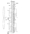
- FIG. 1 is a refrigerant circuit diagram of an air conditioner 100 according to Embodiment 1 of the present invention.
- the air conditioner 100 according to Embodiment 1 includes an outdoor unit 1 and an indoor unit 2, and the outdoor unit 1 and the indoor unit 2 are connected by refrigerant pipes 83, 84 and electric wiring (not shown). It is a separate type.
- the outdoor unit 1 includes a compressor 10, a first flow path switching device 20, a first expansion device 30, a second expansion device 60, a second flow path switching device 70, an outdoor heat exchanger 50, and an outdoor fan. 500, an outside air temperature detection device 200, a first boundary temperature detection device 201, a second boundary temperature detection device 202, and a control device 300.
- the indoor unit 2 includes an indoor heat exchanger 40 and an indoor fan 400.
- the air conditioner 100 has a refrigerant circuit in which a refrigerant circulates.
- the compressor 10, the first flow path switching device 20, the indoor heat exchanger 40, the first expansion device 30, the outdoor heat exchanger 50, and the second flow path switching device 70 are refrigerant pipes 81 to 85, 86A. .About.87A and 86B to 87B, 89 and 91 are sequentially connected.
- Various kinds of refrigerant can be adopted as the refrigerant circulating in the refrigerant circuit, for example, R32 or R410A.
- the discharge side of the compressor 10 and the port A of the second flow path switching device 70 are connected by hot gas bypass pipes 80, 88, and the hot gas bypass pipes 80, 88 are provided with a second expansion device 60. Has been.
- refrigerant pipe 81 One end of the refrigerant pipe 81 is connected to the discharge side of the compressor 10, and the other end branches into a hot gas bypass pipe 80 and a refrigerant pipe 82.
- the refrigerant pipe 82 is connected to the G port of the first flow path switching device 20, and the hot gas bypass pipe 80 is connected to the second expansion device 60.
- the refrigerant pipe 83 connects the H port of the first flow path switching device 20 and the indoor heat exchanger 40.
- the refrigerant pipe 84 connects the indoor heat exchanger 40 and the first expansion device 30.
- the refrigerant pipe 85 is connected to the first expansion device 30, and the other end branches into a refrigerant pipe 86A and a refrigerant pipe 86B.
- the refrigerant pipe 86A is connected to the upper heat exchanger 50A included in the outdoor heat exchanger 50
- the refrigerant pipe 86B is connected to the lower heat exchanger 50B included in the outdoor heat exchanger 50.
- the refrigerant pipe 87A connects the upper heat exchanger 50A and the B2 port of the second flow path switching device 70
- the refrigerant pipe 87B connects the lower heat exchanger 50B and the B1 port of the second flow path switching device 70. ..
- the hot gas bypass pipe 88 connects the second expansion device 60 and the A port of the second flow path switching device 70.
- the refrigerant pipe 89 connects the C port of the second flow path switching device 70 and the E port of the first flow path switching device 20.
- the refrigerant pipe 91 connects the F port of the first flow path switching device 20 and the suction side of the compressor 10.
- the control device 300 includes, for example, dedicated hardware, a CPU (Central Processing Unit, a central processing unit, a processing device, an arithmetic device, a microprocessor, a processor) which executes a program stored in a memory, a RAM, a ROM, or the like. It consists of memory.
- a CPU Central Processing Unit
- a processing device a processing device, an arithmetic device, a microprocessor, a processor
- a program stored in a memory a RAM, a ROM, or the like. It consists of memory.
- the air conditioner 100 There are two types of operation operation of the air conditioner 100 according to the first embodiment, that is, cooling operation and heating operation.
- the heating operation the heating normal operation in which both the upper heat exchanger 50A and the lower heat exchanger 50B function as an evaporator, and one of the upper heat exchanger 50A and the lower heat exchanger 50B is an evaporator.
- heating defrost operation in which the other functions as a condenser. Then, the control device 300 performs one of the driving operations according to the selection by the user.
- the compressor 10 is configured so that the operating frequency can be changed by a control signal received from the control device 300.
- the output of the compressor 10 can be adjusted by changing the operating frequency of the compressor 10.
- Various types of compressors 10 can be adopted, for example, a rotary type, a reciprocating type, a scroll type, or a screw type.
- the first flow path switching device 20 is a device that switches between cooling operation and heating operation, and is, for example, a four-way valve, but may be configured by combining a two-way valve and a three-way valve.
- the heating operation as shown by the solid line in FIG. 1, the refrigerant pipe 82 and the refrigerant pipe 83 which are the discharge pipes of the compressor 10 are connected, and the refrigerant pipe 89 and the refrigerant pipe 91 which is the compressor suction pipe are connected. To do.
- the refrigerant pipe 82 and the refrigerant pipe 89 are connected and the refrigerant pipe 83 and the refrigerant pipe 91 are connected as shown by the broken line in FIG. 1.
- the first expansion device 30 is a device that reduces the pressure of the refrigerant flowing into it, and is, for example, an expansion valve.
- the indoor fan 400 is installed adjacent to the indoor heat exchanger 40 and supplies air to the indoor heat exchanger 40.
- the outdoor fan 500 is attached to the outdoor heat exchanger 50 and supplies air to the outdoor heat exchanger 50.
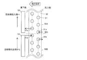
- the outdoor heat exchanger 50 is a fin-tube heat exchanger having heat transfer pipes, a plurality of heat transfer fins 52, and a header 53.
- the heat transfer pipe is composed of a plurality of U-shaped hairpin tubes 51 and a U-bend tube (not shown) connecting the hairpin tubes 51 to each other (see FIGS. 7 and 8 described later).
- the outdoor heat exchanger 50 is composed of an upper heat exchanger 50A and a lower heat exchanger 50B that are divided into two parts, and the upper heat exchanger 50A and the lower heat exchanger 50B are arranged vertically. And are connected in parallel with each other.
- the heat transfer fins 52 are divided in the upper heat exchanger 50A and the lower heat exchanger 50B.
- the heat transfer fins 52 may not be divided. Further, the upper heat exchanger 50A and the lower heat exchanger 50B have flow paths arranged in parallel with each other. The flow direction of the refrigerant will be described when explaining the driving operation.
- the outside air temperature detection device 200 detects the outside air temperature.
- the first boundary temperature detecting device 201 is provided in the inlet pipe of the upper heat exchanger 50A and detects the inlet temperature of the upper heat exchanger 50A. There is a correlation between the temperature detected by the first boundary temperature detecting device 201 and the temperature of the hairpin tube 51 located at the lowermost stage of the upper heat exchanger 50A. Therefore, by correcting the temperature detected by the first boundary temperature detecting device 201, the temperature of the hairpin tube 51 located at the lowermost stage of the upper heat exchanger 50A can be indirectly detected.
- the second boundary temperature detecting device 202 is provided in the inlet pipe of the lower heat exchanger 50B and detects the inlet temperature of the lower heat exchanger 50B.
- the outside air temperature detection device 200, the first boundary temperature detection device 201, and the second boundary temperature detection device 202 are, for example, thermistors.
- the first boundary temperature detecting device 201 may be provided not on the inlet pipe of the upper heat exchanger 50A but on the hairpin tube 51 located at the lowermost stage of the upper heat exchanger 50A.
- the temperature of the hairpin tube 51 located at the lowermost stage of the upper heat exchanger 50A can be directly detected without correcting the temperature detected by the first boundary temperature detection device 201.
- the second boundary temperature detecting device 202 may be provided not at the inlet pipe of the lower heat exchanger 50B but at the hairpin tube 51 located at the uppermost stage of the lower heat exchanger 50B. By doing so, the temperature of the hairpin tube 51 located at the uppermost stage of the lower heat exchanger 50B can be directly detected without correcting the temperature detected by the second boundary temperature detection device 202.
- the hot gas bypass pipes 80 and 88 are provided to utilize a part of the refrigerant discharged from the compressor 10 for defrosting (defrosting) the upper heat exchanger 50A and the lower heat exchanger 50B.
- a second throttling device 60 which is, for example, an expansion valve, is connected to the hot gas bypass pipe 80 as a throttling mechanism. Then, after partially depressurizing a part of the refrigerant discharged from the compressor 10 to an intermediate pressure by the second expansion device 60, one of the upper heat exchanger 50A and the lower heat exchanger 50B via the second flow path switching device 70. , Guides the refrigerant toward the defrost target.
- the compressor 10 sucks the refrigerant from the refrigerant pipe 91 and compresses it.
- the compressed high-temperature high-pressure gas refrigerant is discharged from the compressor 10 and flows into the refrigerant pipe 89 via the refrigerant pipe 81, the refrigerant pipe 82, and the first flow path switching device 20.
- the gas refrigerant flowing through the refrigerant pipe 89 is branched by the second flow path switching device 70 as shown by the solid line in FIG. 1, one flows from the port B2 to the refrigerant pipe 87A, and the other flows from the port B1 to the refrigerant pipe 87B.
- the gas refrigerant branched to the refrigerant pipe 87A flows to the upper heat exchanger 50A, exchanges heat with the outdoor air in the upper heat exchanger 50A, is condensed and becomes a high-pressure liquid refrigerant, and then flows to the refrigerant pipe 86A.
- gas refrigerant branched to the refrigerant pipe 87B flows into the lower heat exchanger 50B, exchanges heat with outdoor air in the lower heat exchanger 50B, is condensed and becomes a high-pressure liquid refrigerant, and then flows into the refrigerant pipe 86B.
- control device 300 can adjust the rotation speed of the outdoor fan 500 by a control signal. Then, by adjusting the rotation speed of the outdoor fan 500 by the control device 300, the amount of air transported to the outdoor heat exchanger 50 changes, and the amount of heat exchanged between the refrigerant and the air in the outdoor heat exchanger 50 can be adjusted. it can.
- the control device 300 can adjust the opening degree of the first expansion device 30 by the control signal. Then, at this time, by adjusting the opening degree of the first expansion device 30 by the control device 300, the depressurizing amount of the refrigerant can be adjusted.
- the refrigerant pressure on the outlet side of the first expansion device 30 increases and the dryness of the refrigerant decreases.
- the refrigerant pressure on the outlet side of the first expansion device 30 decreases and the dryness of the refrigerant increases.
- the liquid refrigerant flowing through the refrigerant pipe 84 flows into the indoor heat exchanger 40, exchanges heat with the indoor air in the indoor heat exchanger 40, evaporates and becomes a low-temperature low-pressure gas refrigerant, and flows into the refrigerant pipe 83.
- control device 300 can adjust the rotation speed of the indoor fan 400 by a control signal. Then, by adjusting the rotation speed of the indoor fan 400 by the control device 300, the amount of air transported to the indoor heat exchanger 40 changes, and the amount of heat exchanged between the refrigerant and the air in the indoor heat exchanger 40 can be adjusted. it can.
- the gas refrigerant flowing through the refrigerant pipe 83 flows from the refrigerant pipe 91 to the compressor 10 again via the first flow path switching device 20.
- the compressor 10 sucks the refrigerant from the refrigerant pipe 91 and compresses it.
- the compressed high-temperature and high-pressure gas refrigerant is discharged from the compressor 10 and flows into the refrigerant pipe 83 via the refrigerant pipe 81, the refrigerant pipe 82, and the first flow path switching device 20.
- the gas refrigerant flowing from the refrigerant pipe 83 into the indoor heat exchanger 40 exchanges heat with the indoor air in the indoor heat exchanger 40, condenses into a high-pressure liquid refrigerant, and flows into the refrigerant pipe 84.
- the control device 300 controls the rotation speed of the indoor fan 400 to the indoor heat exchanger 40 to adjust the amount of heat exchanged between the refrigerant and the air in the indoor heat exchanger 40.
- the liquid refrigerant flowing out from the indoor heat exchanger 40 passes through the refrigerant pipe 84, is decompressed by the first expansion device 30, becomes a low-temperature low-pressure two-phase refrigerant, and flows into the refrigerant pipe 85.
- the decompression amount of the refrigerant can be adjusted.
- the opening degree of the first expansion device 30 is changed in the opening direction, the refrigerant pressure on the outlet side of the first expansion device 30 increases and the dryness of the refrigerant decreases.
- the opening degree of the first expansion device 30 is changed to the closing direction, the refrigerant pressure on the outlet side of the first expansion device 30 decreases and the dryness of the refrigerant increases.
- the two-phase refrigerant flowing through the refrigerant pipe 85 branches into a refrigerant pipe 86A and a refrigerant pipe 86B.
- the two-phase refrigerant branched to the refrigerant pipe 86A flows to the upper heat exchanger 50A, exchanges heat with the outdoor air in the upper heat exchanger 50A, evaporates and becomes a low-temperature low-pressure gas refrigerant, and flows to the refrigerant pipe 87A.
- the two-phase refrigerant branched to the refrigerant pipe 86B flows to the lower heat exchanger 50B, exchanges heat with the outdoor air in the lower heat exchanger 50B, evaporates to become a low-temperature low-pressure gas refrigerant, and then to the refrigerant pipe 87B. Flowing.
- the control device 300 controls the rotation speed of the outdoor fan 500 to the control device 300, the amount of air transported to the outdoor heat exchanger 50 changes, and the amount of heat exchanged between the refrigerant and the air in the outdoor heat exchanger 50 is adjusted. You can
- the gas refrigerant flowing through the refrigerant pipe 87A and the gas refrigerant flowing through the refrigerant pipe 87B are joined by the second flow path switching device 70 as shown by the solid line in FIG. 1, and flow from the C port to the refrigerant pipe 89.
- the gas refrigerant flowing through the refrigerant pipe 89 flows from the refrigerant pipe 91 to the compressor 10 again via the first flow path switching device 20.
- the opening of the second expansion device 60 may be open or fully closed during the normal heating operation. Since the second flow path switching device 70 communicates the port B1 and the port C with each other and the port B2 and the port C with each other, even if the refrigerant is present in the hot gas bypass pipe 88, the port A and other ports are connected to each other. Refrigerant does not flow out to the port.
- heating defrost operation Next, the heating defrost operation will be described.
- the second flow path switching device 70 is operated to alternately defrost the upper heat exchanger 50A and the lower heat exchanger 50B.
- the high-temperature high-pressure gas refrigerant flowing into the hot gas bypass pipe 80 is decompressed by the second expansion device 60, and passes through the hot gas bypass pipe 88, the second flow path switching device 70, and the refrigerant pipe 87A to defrost the upper heat. It flows into the exchanger 50A.
- the high-temperature gas refrigerant that has flowed into the upper heat exchanger 50A condenses while exchanging heat with frost, and defrosts the upper heat exchanger 50A.
- the amount of refrigerant flowing into the upper heat exchanger 50A that is the object of defrosting is adjusted, and the amount of heat exchanged between the refrigerant and frost is adjusted.
- the amount of refrigerant at the outlet of the second expansion device 60 increases, the amount of refrigerant flowing through the upper heat exchanger 50A increases, and the amount of heat exchanged between the refrigerant and frost is increased. Will increase. At this time, the amount of refrigerant flowing through the indoor heat exchanger 40 decreases, so the heating capacity decreases.
- the opening degree of the second expansion device 60 when the opening degree of the second expansion device 60 is changed to the closing direction, the amount of refrigerant at the outlet of the second expansion device 60 decreases, the amount of refrigerant flowing through the upper heat exchanger 50A decreases, and the amount of refrigerant and frost The amount of heat exchanged is reduced. At this time, the amount of refrigerant flowing through the indoor heat exchanger 40 increases, so the heating capacity increases.
- the refrigerant condensed in the upper heat exchanger 50A merges with the refrigerant condensed in the indoor heat exchanger 40 and decompressed in the first expansion device 30 at the confluence of the refrigerant pipe 86A and the refrigerant pipe 85, and then flows into the refrigerant pipe 86B. Flowing.
- the refrigerant flowing through the refrigerant pipe 86B flows into the lower heat exchanger 50B and evaporates. After that, the refrigerant flows from the refrigerant pipe 91 to the compressor 10 again via the refrigerant pipe 87B, the second passage switching device 70, the refrigerant pipe 89, and the first passage switching device 20.
- the hot gas bypass pipe 88 and the refrigerant pipe 87B are The second flow path switching device 70 is operated so that the refrigerant pipe 87A and the refrigerant pipe 89 are connected to each other. Thereby, a part of the high-temperature high-pressure gas refrigerant discharged from the compressor 10 flows into the hot gas bypass pipe 80, and the remaining high-temperature high-pressure gas refrigerant is the refrigerant pipe 82, the first flow path switching device 20, and the refrigerant pipe 83. To the indoor heat exchanger 40 via.
- the high-temperature and high-pressure gas refrigerant flowing into the hot gas bypass pipe 80 is decompressed by the second expansion device 60, passes through the hot gas bypass pipe 88, the second flow path switching device 70, and the refrigerant pipe 87B, and is a target of defrosting. It flows into the side heat exchanger 50B.
- the high-temperature gas refrigerant that has flowed into the lower heat exchanger 50B condenses while exchanging heat with frost, and defrosts the lower heat exchanger 50B.
- the refrigerant condensed in the lower heat exchanger 50B merges with the refrigerant condensed in the indoor heat exchanger 40 and decompressed in the first expansion device 30 at the confluence of the refrigerant pipe 86B and the refrigerant pipe 85, and the refrigerant pipe 86A. Flow to.
- the refrigerant flowing through the refrigerant pipe 86A flows into the upper heat exchanger 50A and evaporates. After that, the refrigerant flows from the refrigerant pipe 91 to the compressor 10 again via the refrigerant pipe 87A, the second passage switching device 70, the refrigerant pipe 89, and the first passage switching device 20.
- the defrosting order of the upper heat exchanger 50A and the lower heat exchanger 50B connected in parallel to each other is such that the lower heat exchanger 50B is defrosted, the upper heat exchanger 50A is defrosted, and then the lower heat exchanger is again defrosted. It is desirable to defrost the heat exchanger 50B. The reason will be described below.
- the frost adhering to the heat transfer fins 52 melts into water droplets, which flow down on the surface of the heat transfer fins 52 of the upper heat exchanger 50A.
- a water droplet or a water stream in which frost is melted is referred to as drain water.
- a part of the drain water flowing down from the upper heat exchanger 50A to the lower heat exchanger 50B is re-iced in the lower heat exchanger 50B functioning as an evaporator.
- the lower heat exchanger 50B is defrosted to defrost the frost generated during the normal heating operation, and then the upper heat exchanger 50A is defrosted to defrost the frost generated during the normal heating operation. Finally, the lower heat exchanger 50B is again defrosted in order to defrost a part of the drain water that has flowed down from the upper heat exchanger 50A and re-freezes. Thereby, the defrost time can be shortened.
- FIG. 2 is a schematic diagram showing a cross section of the outdoor heat exchanger 50 of the conventional air conditioner 100A and the outdoor fan 500.
- FIG. 3 is a schematic diagram showing a cross section near the boundary between the upper heat exchanger 50A and the lower heat exchanger 50B when the upper heat exchanger 50A of the outdoor heat exchanger 50 of the conventional air conditioner 100A is defrosted. It is a figure.
- FIG. 4 shows a cross section near the boundary between the upper heat exchanger 50A and the lower heat exchanger 50B when the lower heat exchanger 50B of the outdoor heat exchanger 50 of the conventional air conditioner 100A is defrosted. It is a schematic diagram.
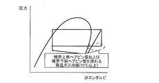
- FIG. 5 is a Mollier diagram during the heating defrost operation of the conventional air conditioner 100A.
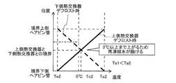
- FIG. 6 is a temperature distribution diagram near the boundary between the upper heat exchanger 50A and the lower heat exchanger 50B during the heating defrost operation of the conventional air conditioner 100A.
- FIGS. 2 to 4 indicate a boundary line 50C between the upper heat exchanger 50A and the lower heat exchanger 50B.
- the black arrows shown in FIGS. 3 and 4 indicate the flow of the refrigerant.
- the thick solid line shown in FIG. 6 indicates the temperature at each position of the upper heat exchanger 50A during defrosting, and the thick broken line shown in FIG. 6 indicates the temperature at each position of the lower heat exchanger 50B during defrosting. Shows.
- FIG. 6 shows the temperature related to the windward side of the hairpin tube 51 (hereinafter, referred to as the boundary upper hairpin tube 51a and the boundary lower hairpin tube 51b) located at the boundary between the upper heat exchanger 50A and the lower heat exchanger 50B.
- the temperature distribution is the same on the leeward side.
- the configuration of the outdoor heat exchanger 50 shown is not limited.
- a high-temperature refrigerant is poured into the lower heat exchanger 50B from one boundary lower hairpin tube 51b, and the lower heat exchanger 50B is defrosted to re-ice (hereinafter, ice). It is called re-freezing).
- the upper heat exchanger 50A serves as an evaporator.
- the evaporation temperature of the refrigerant flowing in the evaporator is lowered, and the amount of frost formed on the heat transfer fins 52 of the evaporator is increased.
- the amount of frost is increased, when the upper heat exchanger 50A is defrosted again, there arises a problem that the heating capacity is lowered and the defrosting completion time becomes long.
- the temperature Ta1 of the lower boundary hairpin tube 51b at the time of defrosting the lower heat exchanger 50B is relatively lower than Ta2 of the first embodiment described later. Further, the temperature Tc1 at the boundary between the upper heat exchanger 50A and the lower heat exchanger 50B becomes 0° C. or lower both when the upper heat exchanger 50A is defrosted and when the lower heat exchanger 50B is defrosted, and 0° C. There is an area that does not grow. And re-freezing does not melt in that area.
- the temperature Te1 shown in FIG. 6 is the temperature of the lower boundary hairpin tube 51b when the upper heat exchanger 50A is defrosted.
- FIG. 7 shows the upper heat exchanger 50A and the lower heat exchanger 50B when the upper heat exchanger 50A of the outdoor heat exchanger 50 of the air conditioner 100 according to Embodiment 1 of the present invention is defrosted.
- It is a schematic diagram which shows the cross section near a boundary.
- FIG. 8 shows an upper heat exchanger 50A and a lower heat exchanger 50B when the lower heat exchanger 50B of the outdoor heat exchanger 50 of the air conditioner 100 according to Embodiment 1 of the present invention is defrosted.
- 3 is a schematic view showing a cross section near the boundary of FIG.
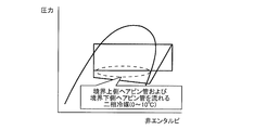
- FIG. 9 is a Mollier diagram during heating defrost operation of air conditioner 100 according to Embodiment 1 of the present invention.
- FIG. 10 is a temperature distribution diagram near the boundary of the outdoor heat exchanger 50 during the heating defrost operation of the air conditioner 100 according to Embodiment 1 of the present invention.
- FIGS. 7 and 8 indicate a boundary line 50C between the upper heat exchanger 50A and the lower heat exchanger 50B.
- the black arrows shown in FIGS. 7 and 8 indicate the flow of the refrigerant.
- the thick solid line shown in FIG. 10 indicates the temperature at each position of the upper heat exchanger 50A during defrosting, and the thick broken line shown in FIG. 10 indicates the temperature at each position of the lower heat exchanger 50B during defrosting. Shows.
- FIG. 10 shows temperature distributions on the windward side of the upper boundary hairpin tube 51a and the lower boundary hairpin tube 51b, similar temperature distributions are also obtained on the leeward side.
- the configuration of the outdoor heat exchanger 50 shown is not limited.
- all the hairpin tubes 51 located at the lowermost stage of the upper heat exchanger 50A to be defrosted are designated as inlets of high-temperature gas refrigerant (hereinafter referred to as refrigerant inlets).
- refrigerant inlets high-temperature gas refrigerant
- all the hairpin tubes 51 located at the uppermost stage of the lower heat exchanger 50B to be defrosted are arranged so as to serve as refrigerant inlets. That is, all the hairpin tubes 51 located at the boundary between the upper heat exchanger 50A and the lower heat exchanger 50B are arranged so as to serve as the refrigerant inlet when defrosting is performed.
- the hairpin tube 51 located at the boundary is the hairpin tube 51 facing the boundary line 50C in the schematic views showing the cross section of the outdoor heat exchanger 50 shown in FIGS. 7 and 8.
- the boundary upper hairpin tube 51a located at the lowermost stage of each row and adjacent to the lower heat exchanger 50B, and in the lower heat exchanger 50B, the uppermost of each row.
- the lower boundary hairpin tube 51b located in the upper stage and adjacent to the upper heat exchanger 50A.
- the heat exchanger 50B is arranged so as to serve as a refrigerant inlet when a defrost target is set.
- two hairpin tubes 51 (boundary upper hairpin tube 51a and lower boundary hairpin tube 51b) are used as the refrigerant when defrosting. It is arranged to be the entrance.
- the number of the hairpin tubes 51 serving as the refrigerant inlets is not limited to two, and when the number of rows of the outdoor heat exchangers 50 is three, the number of the hairpin tubes 51 serving as the refrigerant inlets is three, respectively. It becomes a book.
- the high-temperature gas refrigerant flowing from the refrigerant inlet during the heating defrosting operation becomes a boundary between the upper heat exchanger 50A and the lower heat exchanger 50B as shown in FIG. Flows to the upper boundary hairpin tube 51a or the lower boundary hairpin tube 51b located at. Therefore, the temperatures of the upper boundary hairpin tube 51a, the lower boundary hairpin tube 51b, and the heat transfer fin 52 are likely to rise.
- control device 300 controls the second expansion device 60 to keep the temperature Ta2 (>Ta1) of the lower boundary hairpin tube 51b at a high temperature. Specifically, when the temperature Ta2 of the lower boundary hairpin tube 51b decreases and becomes equal to or lower than a preset temperature Ta1+ ⁇ , the opening degree of the second expansion device 60 is changed to the closing direction. Then, the temperature difference at the boundary between the upper heat exchanger 50A and the lower heat exchanger 50B is increased. By doing so, as shown in FIG. 10, the temperature Tc2 at the boundary between the upper heat exchanger 50A and the lower heat exchanger 50B is at the time of defrosting of the upper heat exchanger 50A and at the time of defrosting of the lower heat exchanger 50B.
- the temperature is higher than 0°C. Therefore, the heating defrost operation does not reach 0° C. or lower in both the upper heat exchanger 50A and the lower heat exchanger 50B, and the drainage near the boundary between the upper heat exchanger 50A and the lower heat exchanger 50B. It can suppress re-freezing of water.
- the compressor 10, the indoor heat exchanger 40, the first expansion device 30, the outdoor heat exchanger 50, and the second flow path switching device 70 are sequentially piped. It is provided with a refrigerant circuit that is connected and circulates the refrigerant. Further, the hot gas bypass pipes 80 and 88 that connect the discharge side of the compressor 10 and the second flow path switching device 70, and the upper heat exchanger 50A and the lower heat exchanger 50B alternate while performing the heating normal operation.
- the controller 300 which performs the heating defrost operation which defrosts.
- the outdoor heat exchanger 50 has a plurality of hairpin tubes 51 forming a part of the heat transfer piping.
- the upper heat exchanger 50A serves as a refrigerant inlet when all the hairpin tubes 51 located at the lowermost stage are defrosted.
- the lower heat exchanger 50B serves as a refrigerant inlet when all the hairpin tubes 51 located at the uppermost stage are defrosted.
- the pipe 51 serves as a refrigerant inlet when defrosted. Therefore, re-freezing of the drain water can be suppressed at the boundary between the upper heat exchanger 50A and the lower heat exchanger 50B, and the reduction of the heating capacity can be suppressed, so that the highly reliable air conditioner 100 is provided. can do.
- the air conditioner 100 includes the second expansion device 60 provided in the hot gas bypass pipes 80 and 88. Further, the first boundary temperature detection device 201 that directly or indirectly detects the temperature of the hairpin tube 51 located at the lowermost stage of the upper heat exchanger 50A, and the hairpin tube located at the uppermost stage of the lower heat exchanger 50B. And a second boundary temperature detection device 202 that directly or indirectly detects the temperature of 51. Then, during the heating defrost operation, the control device 300 causes the second throttle device so that both the temperature detected by the first boundary temperature detecting device 201 and the temperature detected by the second boundary temperature detecting device 202 are higher than 0°C. It controls 60.
- the upper side heat is detected based on the temperature detected by the first boundary temperature detecting device 201 and the temperature detected by the second boundary temperature detecting device 202 during the heating defrosting operation.
- the second expansion device 60 is controlled so that both the temperature of the hairpin tube 51 located at the lowermost stage of the exchanger 50A and the temperature of the hairpin tube 51 located at the uppermost stage of the lower heat exchanger 50B are higher than 0°C. .. Therefore, the heating defrost operation does not become an operation at 0° C. or less in both of the upper heat exchanger 50A and the lower heat exchanger 50B, and the vicinity of the boundary between the upper heat exchanger 50A and the lower heat exchanger 50B. This can prevent the drain water from refreezing.
- the opening of the second expansion device 60, the operating frequency of the compressor 10, and the opening of the first expansion device 30 may be changed as necessary.
- the operating frequency of the compressor 10 may be increased.
- the opening degree of the second expansion device 60 may be changed to the closing direction. In this case, since the flow rate of the refrigerant flowing through the hot gas bypass pipe 88 decreases, the heat exchange amount in the upper heat exchanger 50A or the lower heat exchanger 50B that is the object of defrosting decreases.
- the opening degree of the first expansion device 30 may be changed to the opening direction.
- Embodiment 2 the second embodiment of the present invention will be described, but the description of the same parts as those of the first embodiment will be omitted, and the same or corresponding parts as those of the first embodiment will be designated by the same reference numerals.
- FIG. 11 is a refrigerant circuit diagram of the air conditioner 100 according to Embodiment 2 of the present invention.
- the second flow path switching device 70 is configured by an integrated valve that selectively switches the flow of the refrigerant to the upper heat exchanger 50A side or the lower heat exchanger 50B side.
- the second flow path switching device 70 is composed of four electromagnetic valves 70A to 70D. Even if the second flow path switching device 70 has such a configuration, the same effect as that of the first embodiment can be obtained.
- Embodiment 3 Hereinafter, the third embodiment of the present invention will be described, but the description of the same parts as those of the first embodiment will be omitted, and the same or corresponding parts as those of the first embodiment will be designated by the same reference numerals.
- FIG. 12 is a refrigerant circuit diagram of the air conditioner 100 according to Embodiment 3 of the present invention.
- the second flow path switching device 70 is configured by an integrated valve that selectively switches the flow of the refrigerant to the upper heat exchanger 50A side or the lower heat exchanger 50B side.
- the second flow path switching device 70 is composed of two three-way valves 600 and 700. Even if the second flow path switching device 70 has such a configuration, the same effect as that of the first embodiment can be obtained.
- FIG. 13 is a refrigerant circuit diagram of the air conditioner 100 according to Embodiment 4 of the present invention.
- the second flow path switching device 70 is configured by an integrated valve that selectively switches the flow of the refrigerant to the upper heat exchanger 50A side or the lower heat exchanger 50B side.
- the second flow path switching device 70 is composed of two three-way valves 600A and 700A. Since these two three-way valves 600A and 700A are operated by differential pressure, respectively, in order to secure the differential pressure, the E port of the first flow path switching device 20, the Q port of the three-way valve 600A, and the U port of 700A are provided. A check valve 90 is provided between the two. Even if the second flow path switching device 70 has such a configuration, the same effect as that of the first embodiment can be obtained.
Landscapes
- Engineering & Computer Science (AREA)
- Mechanical Engineering (AREA)
- General Engineering & Computer Science (AREA)
- Physics & Mathematics (AREA)
- Thermal Sciences (AREA)
- Chemical & Material Sciences (AREA)
- Combustion & Propulsion (AREA)
- Air Conditioning Control Device (AREA)
- Other Air-Conditioning Systems (AREA)
- Compression-Type Refrigeration Machines With Reversible Cycles (AREA)
Abstract
La présente invention concerne un climatiseur pourvu d'un circuit de réfrigération dans lequel sont reliés de manière séquentielle par une tuyauterie un compresseur destiné à comprimer et décharger un fluide frigorigène, un échangeur de chaleur intérieur destiné à réaliser un échange de chaleur entre le fluide frigorigène et l'air intérieur, un premier dispositif d'étranglement destiné à décompresser le fluide frigorigène, un échangeur de chaleur extérieur qui est constitué d'un échangeur de chaleur côté supérieur et d'un échangeur de chaleur côté inférieur ayant des passages d'écoulement parallèles les uns aux autres et qui réalise un échange de chaleur entre le fluide frigorigène et l'air extérieur, et un dispositif de commutation de passage d'écoulement destiné à commuter l'écoulement du fluide frigorigène vers le côté de l'échangeur de chaleur côté supérieur ou vers le côté de l'échangeur de chaleur côté inférieur, et à travers lequel circule le fluide frigorigène, une tuyauterie de dérivation de gaz chaud reliant le côté de décharge du compresseur et le dispositif de commutation de passage d'écoulement, et un dispositif de commande destiné à effectuer une opération de dégivrage par chauffage d'espace pour dégivrer l'échangeur de chaleur côté supérieur et l'échangeur de chaleur côté inférieur en alternance tout en réalisant une opération de chauffage d'espace normal. Selon l'invention : l'échangeur de chaleur extérieur comprend une pluralité de tubes en épingle à cheveux constituant une portion de la tuyauterie de transfert de chaleur ; l'échangeur de chaleur côté supérieur sert d'entrée de fluide frigorigène lorsque tous les tubes en épingle à cheveux situés dans un niveau le plus bas sont dégivrés ; et l'échangeur de chaleur côté inférieur sert d'entrée de fluide frigorigène lorsque tous les tubes en épingle à cheveux situés dans un niveau supérieur sont dégivrés.
Priority Applications (5)
| Application Number | Priority Date | Filing Date | Title |
|---|---|---|---|
| US17/278,939 US20220049869A1 (en) | 2018-12-04 | 2018-12-04 | Air-conditioning apparatus |
| CN201880099720.4A CN113167486B (zh) | 2018-12-04 | 2018-12-04 | 空调机 |
| JP2020558709A JP6964803B2 (ja) | 2018-12-04 | 2018-12-04 | 空気調和機 |
| PCT/JP2018/044519 WO2020115812A1 (fr) | 2018-12-04 | 2018-12-04 | Climatiseur |
| EP18942549.9A EP3892928B1 (fr) | 2018-12-04 | 2018-12-04 | Appareil d'air conditionné |
Applications Claiming Priority (1)
| Application Number | Priority Date | Filing Date | Title |
|---|---|---|---|
| PCT/JP2018/044519 WO2020115812A1 (fr) | 2018-12-04 | 2018-12-04 | Climatiseur |
Publications (1)
| Publication Number | Publication Date |
|---|---|
| WO2020115812A1 true WO2020115812A1 (fr) | 2020-06-11 |
Family
ID=70975423
Family Applications (1)
| Application Number | Title | Priority Date | Filing Date |
|---|---|---|---|
| PCT/JP2018/044519 WO2020115812A1 (fr) | 2018-12-04 | 2018-12-04 | Climatiseur |
Country Status (5)
| Country | Link |
|---|---|
| US (1) | US20220049869A1 (fr) |
| EP (1) | EP3892928B1 (fr) |
| JP (1) | JP6964803B2 (fr) |
| CN (1) | CN113167486B (fr) |
| WO (1) | WO2020115812A1 (fr) |
Cited By (1)
| Publication number | Priority date | Publication date | Assignee | Title |
|---|---|---|---|---|
| CN111637593A (zh) * | 2020-05-25 | 2020-09-08 | 宁波奥克斯电气股份有限公司 | 一种能延缓结霜的空调器及其控制方法 |
Families Citing this family (2)
| Publication number | Priority date | Publication date | Assignee | Title |
|---|---|---|---|---|
| JP7185158B1 (ja) * | 2021-10-07 | 2022-12-07 | ダイキン工業株式会社 | 熱源ユニット、および空気調和装置 |
| CN115419965B (zh) * | 2022-09-14 | 2024-08-09 | 珠海格力电器股份有限公司 | 空调器及其控制方法及装置 |
Citations (4)
| Publication number | Priority date | Publication date | Assignee | Title |
|---|---|---|---|---|
| JP2008064381A (ja) | 2006-09-07 | 2008-03-21 | Hitachi Appliances Inc | 空気調和機 |
| JP2010139097A (ja) * | 2008-12-09 | 2010-06-24 | Mitsubishi Electric Corp | 空気調和機 |
| WO2016113850A1 (fr) * | 2015-01-13 | 2016-07-21 | 三菱電機株式会社 | Dispositif de climatisation |
| WO2016117131A1 (fr) * | 2015-01-23 | 2016-07-28 | 三菱電機株式会社 | Unité extérieure de climatiseur |
Family Cites Families (13)
| Publication number | Priority date | Publication date | Assignee | Title |
|---|---|---|---|---|
| US5219023A (en) * | 1992-03-09 | 1993-06-15 | General Motors Corporation | Three row condenser with high efficiency flow path |
| US5315836A (en) * | 1993-01-15 | 1994-05-31 | Mccormack Manufacturing Co., Inc. | Air cooling unit having a hot gas defrost circuit |
| JP4760542B2 (ja) * | 2006-05-31 | 2011-08-31 | ダイキン工業株式会社 | 熱交換器 |
| JP2009264605A (ja) * | 2008-04-22 | 2009-11-12 | Daikin Ind Ltd | 冷凍装置 |
| KR20100081621A (ko) * | 2009-01-06 | 2010-07-15 | 엘지전자 주식회사 | 공기조화기 및 공기조화기의 제상운전방법 |
| CN102338592B (zh) * | 2010-07-27 | 2013-04-24 | 约克广州空调冷冻设备有限公司 | 用于空调热泵的热交换器 |
| WO2013111177A1 (fr) * | 2012-01-24 | 2013-08-01 | 三菱電機株式会社 | Unité de climatisation |
| EP2927623B1 (fr) * | 2012-11-29 | 2019-02-06 | Mitsubishi Electric Corporation | Dispositif de conditionnement d'air |
| WO2015059945A1 (fr) * | 2013-10-24 | 2015-04-30 | 三菱電機株式会社 | Climatiseur |
| US20160123645A1 (en) * | 2014-10-29 | 2016-05-05 | Lg Electronics Inc. | Air conditioner and method of controlling the same |
| US10415860B2 (en) * | 2015-09-09 | 2019-09-17 | Mitsubishi Electric Corporation | Air-conditioning apparatus |
| JP6576552B2 (ja) * | 2016-05-16 | 2019-09-18 | 三菱電機株式会社 | 空気調和装置 |
| KR102447943B1 (ko) * | 2018-02-05 | 2022-09-28 | 엘지전자 주식회사 | 공기조화기 |
-
2018
- 2018-12-04 WO PCT/JP2018/044519 patent/WO2020115812A1/fr unknown
- 2018-12-04 EP EP18942549.9A patent/EP3892928B1/fr active Active
- 2018-12-04 JP JP2020558709A patent/JP6964803B2/ja active Active
- 2018-12-04 CN CN201880099720.4A patent/CN113167486B/zh active Active
- 2018-12-04 US US17/278,939 patent/US20220049869A1/en not_active Abandoned
Patent Citations (4)
| Publication number | Priority date | Publication date | Assignee | Title |
|---|---|---|---|---|
| JP2008064381A (ja) | 2006-09-07 | 2008-03-21 | Hitachi Appliances Inc | 空気調和機 |
| JP2010139097A (ja) * | 2008-12-09 | 2010-06-24 | Mitsubishi Electric Corp | 空気調和機 |
| WO2016113850A1 (fr) * | 2015-01-13 | 2016-07-21 | 三菱電機株式会社 | Dispositif de climatisation |
| WO2016117131A1 (fr) * | 2015-01-23 | 2016-07-28 | 三菱電機株式会社 | Unité extérieure de climatiseur |
Non-Patent Citations (1)
| Title |
|---|
| See also references of EP3892928A4 |
Cited By (1)
| Publication number | Priority date | Publication date | Assignee | Title |
|---|---|---|---|---|
| CN111637593A (zh) * | 2020-05-25 | 2020-09-08 | 宁波奥克斯电气股份有限公司 | 一种能延缓结霜的空调器及其控制方法 |
Also Published As
| Publication number | Publication date |
|---|---|
| CN113167486A (zh) | 2021-07-23 |
| CN113167486B (zh) | 2022-10-14 |
| EP3892928A1 (fr) | 2021-10-13 |
| JPWO2020115812A1 (ja) | 2021-09-02 |
| JP6964803B2 (ja) | 2021-11-10 |
| EP3892928B1 (fr) | 2024-07-24 |
| EP3892928A4 (fr) | 2021-12-15 |
| US20220049869A1 (en) | 2022-02-17 |
Similar Documents
| Publication | Publication Date | Title |
|---|---|---|
| EP3477222B1 (fr) | Dispositif à cycle de réfrigération | |
| JP6685409B2 (ja) | 空気調和装置 | |
| US8424333B2 (en) | Air conditioner | |
| JP4874223B2 (ja) | 空気調和機 | |
| EP1521046A2 (fr) | Circuit de fluide frigorigène et appareil de distribution d'eau chaude avec pompe à chaleur | |
| JP6678332B2 (ja) | 空気調和機の室外ユニットおよび制御方法 | |
| WO2013001976A1 (fr) | Climatiseur | |
| EP2211127A1 (fr) | Climatiseur de type pompe à chaleur | |
| JP2008256304A (ja) | 冷凍装置 | |
| KR20100096182A (ko) | 냉동 장치 | |
| WO2020115812A1 (fr) | Climatiseur | |
| JP7042906B2 (ja) | 空気調和機 | |
| JP6285172B2 (ja) | 空気調和機の室外機 | |
| WO2005024313A1 (fr) | Congelateur | |
| JP5734205B2 (ja) | 空気調和装置 | |
| WO2021053820A1 (fr) | Climatiseur | |
| JP2010203673A (ja) | 空気調和装置 | |
| JP2009243842A (ja) | マルチ型空気調和機および室外機の運転方法 | |
| JP6664503B2 (ja) | 空気調和装置 | |
| KR101692243B1 (ko) | 캐스캐이드 사이클을 이용한 히트 펌프 | |
| JP7098064B2 (ja) | 空気調和機 | |
| JP2013204952A (ja) | 冷凍サイクル装置 | |
| WO2021014520A1 (fr) | Dispositif de climatisation | |
| CN117355721A (zh) | 热交换器、具备热交换器的空调装置的室外机、以及具备空调装置的室外机的空调装置 | |
| JP2005233451A (ja) | 空気調和装置 |
Legal Events
| Date | Code | Title | Description |
|---|---|---|---|
| 121 | Ep: the epo has been informed by wipo that ep was designated in this application |
Ref document number: 18942549 Country of ref document: EP Kind code of ref document: A1 |
|
| ENP | Entry into the national phase |
Ref document number: 2020558709 Country of ref document: JP Kind code of ref document: A |
|
| NENP | Non-entry into the national phase |
Ref country code: DE |
|
| ENP | Entry into the national phase |
Ref document number: 2018942549 Country of ref document: EP Effective date: 20210705 |