WO2020111206A1 - 撹拌棒および撹拌装置 - Google Patents
撹拌棒および撹拌装置 Download PDFInfo
- Publication number
- WO2020111206A1 WO2020111206A1 PCT/JP2019/046677 JP2019046677W WO2020111206A1 WO 2020111206 A1 WO2020111206 A1 WO 2020111206A1 JP 2019046677 W JP2019046677 W JP 2019046677W WO 2020111206 A1 WO2020111206 A1 WO 2020111206A1
- Authority
- WO
- WIPO (PCT)
- Prior art keywords
- stirring
- stirring rod
- rod according
- liquid contact
- contact surface
- Prior art date
- Legal status (The legal status is an assumption and is not a legal conclusion. Google has not performed a legal analysis and makes no representation as to the accuracy of the status listed.)
- Ceased
Links
Images



Classifications
-
- B—PERFORMING OPERATIONS; TRANSPORTING
- B01—PHYSICAL OR CHEMICAL PROCESSES OR APPARATUS IN GENERAL
- B01F—MIXING, e.g. DISSOLVING, EMULSIFYING OR DISPERSING
- B01F27/00—Mixers with rotary stirring devices in fixed receptacles; Kneaders
- B01F27/80—Mixers with rotary stirring devices in fixed receptacles; Kneaders with stirrers rotating about a substantially vertical axis
-
- G—PHYSICS
- G01—MEASURING; TESTING
- G01N—INVESTIGATING OR ANALYSING MATERIALS BY DETERMINING THEIR CHEMICAL OR PHYSICAL PROPERTIES
- G01N35/00—Automatic analysis not limited to methods or materials provided for in any single one of groups G01N1/00 - G01N33/00; Handling materials therefor
- G01N35/02—Automatic analysis not limited to methods or materials provided for in any single one of groups G01N1/00 - G01N33/00; Handling materials therefor using a plurality of sample containers moved by a conveyor system past one or more treatment or analysis stations
Definitions
- the present disclosure relates to a stirring rod for stirring a liquid and a stirring device including the stirring rod.
- an analyzer that analyzes blood, urine, and other biochemical samples, mainly for medical purposes, is equipped with a stirring device that stirs the sample solution.
- This stirring device is equipped with a stirring rod for stirring the sample solution.
- the stir bar is required to have chemical resistance to sample solutions, reagents and the like.
- the stirring rod is made of, for example, a metal material such as stainless steel or a resin material such as polyethylene or polypropylene which is surface-treated using a fluororesin.
- a stainless steel stirring rod whose surface is coated with a fluororesin such as tetrafluoroethylene, trifluoroethylene, chlorotrifluoroethylene, FEP (copolymer of tetrafluoroethylene and hexafluoropropylene) has durability and cost. It is preferably used from the viewpoint of (for example, Patent Documents 1 and 2).
- the stirring rod of the present disclosure is an integrally molded ceramic product having a stirring portion having a cross section orthogonal to the axial center and having a constant shape along the axial direction. It is arranged.
- the stirring device of the present disclosure includes the stirring rod described above.
- FIG. 5 is a schematic view showing a manufacturing process of the stirring rod of the present disclosure. It is a schematic diagram for explaining the warp of the stirring rod of the present disclosure. It is a schematic diagram showing a use state of a stirring rod of the present disclosure.
- (A) And (b) is a front view which shows other embodiments of the stirring rod of this indication, respectively.
- the stirring rod 1 has a stirring unit 2 and a stirring unit having the same axial center A as the stirring unit 2 on one end face in the axial direction of the stirring unit 2. 2 and a shaft portion 3 formed integrally.
- the stirring unit 2 has a cross section orthogonal to the axis A having a constant shape over the entire length of the stirring unit 2 along the axial direction. That is, as shown in FIG. 1B, the cross section of the stirring section 2 has a shape in which a plurality of convex sections 4 are arranged in the circumferential direction. Since the stirring rod 1 according to the present embodiment includes the plurality of convex portions 4, it is possible to stir by generating a flow in the axial direction.
- the stir bar 1 is made of ceramics integrally molded with excellent chemical resistance. That is, the stirring portion 2 having a cross-sectional shape in which the plurality of convex portions 4 are arranged in the circumferential direction over the entire length can be obtained by, for example, extrusion molding.
- Extrusion is performed according to the following procedure. First, water and a binder (binder) are added to and mixed with a raw material (powder), and the mixture is continuously supplied into the cylinder to be heated and melted. Next, the molten material is extruded through a die at the front of the cylinder by rotation of a screw in the cylinder, cooled, and molded.
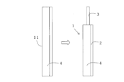
- the extruded molded product 11 shown in FIG. 2 has the cross-sectional shape shown in FIG. 1(b) over the entire length. After firing the molded product 11, one end is ground and polished while the molded product 11 is rotated in the grinding/polishing process to form the shaft portion 3. At this time, the shaft portion 3 and the stirring portion 2 have the common axis A.
- the cross-sectional shape of the shaft portion 3 is not particularly limited, and examples thereof include a circular shape, a quadrangular shape, and an elliptical shape.
- the raw material of such ceramics is not particularly limited as long as it has excellent chemical resistance, and examples thereof include high-purity alumina, zirconia, silicon nitride, silicon carbide, and alumina-zirconia composite material.
- the plurality of convex portions 4 arranged in the circumferential direction of the stirring unit 2 extend radially from the axis A in the radial direction, and the convex portions 4 are arranged at equal intervals. There is.
- the convex portion 4 has a tapered shape whose width becomes narrower toward the tip. With such a tapered shape, the resistance (stress) received by the tip of the convex portion 4 is reduced, and the durability is improved.
- the entire convex portion 4 is formed into a curved surface. Therefore, the space between the adjacent convex portions 4 and 4, that is, the valley portion is also curved.
- the angle between the adjacent convex portions 4 is larger than the angle obtained by dividing 360° by the number of convex portions 4. That is, each convex portion 4 is thinner than the root portion at a position distant from the axis A. Therefore, there is an effect that a reagent or the like is less likely to accumulate in the gap between the convex portions 4. Further, there is an effect that it is easy to polish even during manufacturing.
- the angle ⁇ between the adjacent convex portions 4 and 4 may be larger than the angle ⁇ by 1/4 ⁇ or more when ⁇ is an angle obtained by dividing 360° by the number of the convex portions 4.
- the angle ⁇ between the adjacent convex portions 4 and 4 may form an obtuse angle of 90° or more.
- the angle ⁇ may be in the range of 90° ⁇ 180°.
- the angle ⁇ means the angle formed by the tangents of the portions of the adjacent convex portions 4 and 4 that are closest to the valley portion.
- the convex portion 4 having a shape as shown in FIG. 1B, it means the angle between the outer tangent line of one convex portion 4 and the inner tangent line of the other convex portion 4.
- the stirring rod 1 may have a shape in which the axis A is curved in an arc shape.
- the stirring portion 2 is shown as warped, but the shaft center A of the shaft portion 3 is also warped.
- x the distance most distant from the vertical line in the stirring section 2 shown in FIG. 3 is preferably 0.2 mm or less.
- X shown in FIG. 3 can be measured by, for example, a gap gauge or the like.
- the stirring efficiency is improved by the warp of the stirring unit 2.
- the temperature and the firing time during firing of the molded product 11 may be controlled.
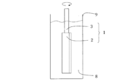
- the stirring rod 1 is inserted into the stirring tank 9 of the stirring device with the stirring unit 2 facing downward.
- the upper portion of the shaft portion 3 projects from the liquid surface of the sample solution 8.
- a drive unit (not shown) including a motor for rotating the stirring rod 1 is connected to the shaft portion 3 protruding from the liquid surface, and the stirring rod 1 is rotated.
- the stirring unit 2 of the stirring rod 1 in this embodiment is located at least near the bottom of the stirring tank 9, stirring can be performed efficiently regardless of the viscosity of the sample solution 8. Particularly, when the stirring section 2 is formed to be long in the axial direction, it is suitable for stirring the high-viscosity sample solution 8.
- the stirring unit 2 may have a half or less of the depth of the sample solution 8 (the height from the bottom surface of the stirring tank 9 to the liquid surface).
- the stirring rod of the present disclosure is not limited to the embodiment of FIG. 1, and various modifications are possible.
- the stirring unit 2 may be at the bottom, and as shown in FIG. 5( b ), a plurality of stirring units 2 a, 2 b, 2 c may be provided along the shaft 3. It may be arranged in the same manner.
- the number of convex portions 4 provided on the shaft portion 3 is not limited to the four shown in the figure, and can be appropriately selected within the range of 2 to 5.
- the shaft portion 3 is integrally formed with the stirring portion 2 by extrusion molding or the like.
- the shaft portion 3 is manufactured separately from the stirring portion 2, and the shaft portion 3 is formed in a recess provided on the end surface of the stirring portion 2.
- the shaft portion 3 may be attached and fixed.
- the shaft portion 3 may have a circular or elliptical cross section, or may have a quadrangular shape for preventing idling.
- the ceramic may have closed pores, and the value (A) obtained by subtracting the average value of the circle equivalent diameters of the closed pores from the distance between the centers of gravity of the adjacent closed pores may be 20 ⁇ m to 85 ⁇ m.
- the value (A) is 20 ⁇ m or more, void portions are dispersed and arranged without being dense, and thus high mechanical properties are obtained.
- the value (A) is 85 ⁇ m or less, it is good when processing such as polishing from the outer peripheral surface of the stirring section 2 in the axial direction or from the end surface of the stirring section 2 or the end surface of the shaft section 3 to the inside. Good workability can be obtained. Further, since the space between the adjacent closed pores is narrowed, it is possible to suppress the extension of microcracks caused by thermal shock.
- the distance between the centers of gravity of closed pores can be obtained by the following method.
- a copper plate is used for polishing from the end face of the stirring unit 2 toward the inside by using diamond abrasive grains having an average particle diameter D 50 of 3 ⁇ m.
- a polished surface is obtained by polishing with a tin plate using diamond abrasive grains having an average particle diameter D 50 of 0.5 ⁇ m.
- the arithmetic average roughness Ra of the polished surface can be 0.01 ⁇ m to 0.2 ⁇ m.
- the arithmetic average roughness Ra of the polished surface can be determined according to JIS B 0601:1994, the radius of the stylus is 5 ⁇ m, the material of the stylus is diamond, the measurement length is 1.25 mm, and the cutoff value is It may be 0.25 mm.
- the polished surface is observed at a magnification of 200 times, and an average range is selected.
- a range in which the area is 0.105 mm 2 (horizontal length 374 ⁇ m, vertical length 280 ⁇ m) is CCD
- the image analysis software “A image-kun (ver2.52)” registered trademark, manufactured by Asahi Kasei Engineering Co., Ltd.
- the distance between the centers of gravity of the closed pores was measured by a method called the distance between centers of gravity measurement of the degree of dispersion. Find the distance.
- the image analysis software “A image-kun” it means image analysis software manufactured by Asahi Kasei Engineering Co., Ltd.
- a threshold value which is an index showing the brightness of an image, is 86, brightness is dark, small figure removal area is 1 ⁇ m 2 , and a noise removal filter is provided.
- the threshold value may be adjusted according to the brightness of the observed image. The brightness was set to dark, the binarization method was set to manual, the small figure removal area was set to 1 ⁇ m 2 and a noise removal filter was provided. Adjust the value.
- the silicon concentration on the liquid contact surface is higher than the silicon concentration on an internal virtual surface parallel to the liquid contact surface.
- a color mapping image of silicon (electron beam microanalyzer (EPMA)) was used for the polished cross section including the liquid contact surface (horizontal length 120 ⁇ m, vertical length: 90 ⁇ m). You can observe.
- EPMA electron beam microanalyzer
- the ceramic on the liquid contact surface of the convex portion 4 has a plurality of crystal grains and a grain boundary phase, and the width (w) of the grain boundary phase located between the adjacent crystal grains is 0.7 ⁇ m to
- the ratio (d/w) of the depth (d) of the grain boundary phase to the width (w) of the grain boundary phase may be 0.06 to 0.18.
- the width (w) of the grain boundary phase is in the above range and the ratio (d/w) of the depth (d) of the grain boundary phase is 0.18 or less, the binding force between crystal grains due to the grain boundary phase Is maintained sufficiently, the risk of shedding is reduced even when high-pressure washing is performed using a water-soluble detergent.
- the width (w) and the depth (d) of the grain boundary phase an atomic force microscope (7500AFM/SPM manufactured by Keysight Technology) was used, the measurement mode was ACAFM mode, and the scanning speed of the probe used for measurement was 0.15lines. /Sec, the measurement area is 20 ⁇ m ⁇ 20 ⁇ m, the length of the measurement target is 7 ⁇ m to 20 ⁇ m, and the resolution is 512 pixels ⁇ 512 pixels, the cross-sectional profile of the liquid contact surface is obtained, and the ratio (d/w) is the grain boundary phase. It may be calculated using the respective measured values of the width (w) and the depth (d).
- the average diameter of the crystal particles of the ceramics on the liquid contact surface of the convex portion 4 may be 2 ⁇ m to 8 ⁇ m.
- the contact angle with respect to pure water becomes smaller, so that the efficiency of removing stains can be increased when the particles are washed with a water-soluble detergent.
- the average diameter of crystal particles of ceramics can be obtained as follows.
- the observation surface is obtained by etching the polished surface at a temperature of, for example, 1480° C. until the crystal particles and the grain boundary layer can be distinguished from each other.
- a backscattered electron image of the observation surface was magnified 2000 times in a range of 60 ⁇ m ⁇ 44 ⁇ m, and a straight line of the same length, for example, 30 ⁇ m, was drawn radially around an arbitrary point,
- the average diameter can be obtained by dividing the total length of the straight line by the total number of crystals existing on the straight line.
- the contact angle of the liquid contact surface of the convex portion 4 with respect to pure water may be 37° or less and the coefficient of variation thereof may be 0.02 or less.
- At least one of the side surface and the end surface of the convex portion 4 may be covered with a film made of a compound containing fluorinated polysiloxane. After washing with a water-soluble detergent, the Lotus effect that water droplets adhering to the surface covered with the above film adsorb the dirt can be obtained, so that the dirt removal efficiency can be increased.
- the contact angle of the liquid contact surface of the membrane with pure water may be 104° or more, and the coefficient of variation may be 0.01 or less.
- the contact angle of the liquid contact surface can be determined according to JIS R 3257:1999. For example, if a contact angle meter (manufactured by Kyowa Interface Science Co., Ltd., model CA-X) is used, it can be measured at 5 or more points. Good.
- the manufacturing method of the stirring rod of the present disclosure will be described when the stirring rod is made of high-purity alumina ceramics.
- Aluminum oxide powder (purity of 99.9 mass% or more) as the main component, and magnesium hydroxide, silicon oxide, and calcium carbonate powders were mixed with an organic binder, a plasticizer, a lubricant, and ion-exchanged water. After being stirred using a universal stirrer, a rotary mill, a V-type stirrer, or the like, further kneading is performed using a three-roll mill, a kneader, or the like to obtain a plasticized kneaded clay.
- the content of the magnesium hydroxide powder is 0.43 to 0.53 mass%
- the content of the silicon oxide powder is 0.02 to 0.04 mass%
- the content of the calcium carbonate powder is 100% by mass.
- the content is 0.020 to 0.071% by mass
- the balance is aluminum oxide powder and unavoidable impurities.
- the organic binder is a water-soluble binder such as methyl cellulose or hydroxypropyl methyl cellulose.
- the kneaded material is molded by an extrusion molding machine, the precursor of the stirring portion having a plurality of convex portions, and the precursor of the shaft portion having the same axial center as this precursor on one end face in the axial direction of the precursor A molded body having and is obtained.
- the stirring bar of the present disclosure can be obtained by firing the molded body at a firing temperature of 1500° C. to 1700° C. and a holding time of 4 hours to 6 hours.
- At least one of the side face and the end face of the convex portion may be polished, and then heat-treated at a temperature of 1600° C. to 1700° C. for 1 hour to 4 hours. It is possible to obtain a stirring bar in which the contact angle of the liquid contact surface of the part to pure water is 37° or less and the coefficient of variation is 0.02 or less.
- a surface pressure applied to the side surface or the end surface to be polished is 0.03 MPa to 0.05 MPa, and a lapping machine made of diamond abrasive grains having an average grain size of 1 ⁇ m to 2 ⁇ m and copper may be used.
- At least one of the side surface and the end surface of the convex portion is at least a target of coating.
- the surface of the convex portion may be coated by a method such as flow coating, dipping or spraying, and then dried at, for example, 130°C to 150°C.
Landscapes
- Chemical & Material Sciences (AREA)
- General Health & Medical Sciences (AREA)
- Immunology (AREA)
- Health & Medical Sciences (AREA)
- Analytical Chemistry (AREA)
- Biochemistry (AREA)
- Physics & Mathematics (AREA)
- General Physics & Mathematics (AREA)
- Life Sciences & Earth Sciences (AREA)
- Pathology (AREA)
- Chemical Kinetics & Catalysis (AREA)
- Accessories For Mixers (AREA)
- Mixers Of The Rotary Stirring Type (AREA)
- Porous Artificial Stone Or Porous Ceramic Products (AREA)
- Compositions Of Oxide Ceramics (AREA)
Abstract
本開示に係る撹拌棒1は、軸心に直交する断面が軸方向に沿って一定の形状を有する撹拌部を備えた、セラミックスの一体成形品からなり、前記断面において、複数の凸部4が周方向に配置されている撹拌部2を有する。複数の凸部4は、前記断面において先端に向かって幅が細くなる先細形状を有する。
Description
本開示は、液体を撹拌するための撹拌棒およびこの撹拌棒を備えた撹拌装置に関する。
従来、主として医療目的で、血液、尿、その他の生化学的試料を分析する分析装置には、試料溶液を撹拌する撹拌装置が搭載されている。この撹拌装置には試料溶液を撹拌するための撹拌棒が備えられている。撹拌棒には試料溶液や試薬等に対して耐薬品性が求められる。そのために、撹拌棒は、例えばフッ素系樹脂を用いて表面加工したステンレス等の金属材料や、ポリエチレン、ポリプロピレンなどの樹脂材料から形成されている。中でも、テトラフルオロエチレン、トリフルオロエチレン,クロロトリフルオロエチレン、FEP(テトラフルオロエチレンとヘキサフルオロプロピレンの共重合体)等のフッ素系樹脂で表面を被覆したステンレス製の撹拌棒が、耐久性とコストの面から好適に使用されている(例えば、特許文献1、2)。
本開示の撹拌棒は、軸心に直交する断面が軸方向に沿って一定の形状を有する撹拌部を備えた、セラミックスの一体成形品からなり、上記断面において、複数の凸部が周方向に配置されている。
本開示の撹拌装置は、上記の撹拌棒を備える。
以下、本開示の一実施形態に係る撹拌棒を図面に基づいて説明する。図1(a)に示すように、本実施形態に係る撹拌棒1は、撹拌部2と、この撹拌部2の軸方向の一端面に撹拌部2と同一軸心Aを有するように撹拌部2と一体に形成された軸部3とを備えている。
撹拌部2は、軸心Aに直交する断面が軸方向に沿った撹拌部2の全長にわたって一定の形状を有する。すなわち、図1(b)に示すように、撹拌部2の断面は、複数の凸部4が周方向に配置された形状を有する。本実施形態に係る撹拌棒1は、複数の凸部4を備えていることにより軸方向に流れを発生させて撹拌することができる。
撹拌棒1は、耐薬品性に優れたセラミックスの一体成形品からなる。すなわち、複数の凸部4が周方向に配置された断面形状を全長にわたって有する撹拌部2は、例えば、押出成形により得ることができる。
押出成形は以下の手順で行う。まず、原料(粉末状)に水およびバインダー(粘結剤)を添加・混合してシリンダ内に連続供給して加熱溶融させる。次に、この溶融した材料を、シリンダ内のスクリューの回転によってシリンダ前部のダイスを通して押し出し、冷却して成形する。図2に示す押し出された成形品11は、全長にわたって図1(b)に示す断面形状を有する。この成形品11を焼成後、研削・研磨工程にて成形品11を回転させながら一端部を研削・研磨して軸部3を形成する。このとき、軸部3と撹拌部2とは軸心Aを共通にする。
なお、軸部3の断面形状は特に限定されず、例えば円形、四角形、楕円形状等が挙げられる。
また、研削・研磨工程では、焼成された撹拌棒1のバリや傷を除去し、平滑にする。このとき、撹拌部2の周面、とくに凸部4は全面を曲面状にするのが好ましい。これにより、撹拌棒1に部分的な応力集中が発生せず、ヒビや破損が減少し、耐久性が向上する。
このようなセラミックスの原材料としては、耐薬品性に優れたものであれば特に限定されず、例えば高純度アルミナ、ジルコニア、窒化ケイ素、炭化ケイ素、アルミナジルコニア複合材料などが挙げられる。
図1(b)に戻って、撹拌部2の周方向に配置された複数の凸部4は、軸心Aから半径方向に放射状に延びており、各凸部4は等間隔で配置されている。
また、凸部4は先端に向かって幅が細くなる先細形状を有している。このような先細形状であれば、凸部4の先端部が受ける抵抗(応力)が軽減され、耐久性が向上する。
前記したように、凸部4は全面が曲面状に形成されている。そのため、隣接する凸部4,4の間、すなわち谷部も曲面状である。
本実施形態では、隣接する凸部4間の角度が360°を凸部4の個数で除した角度よりも大きい。すなわち、各凸部4は、付け根部よりも、軸心Aから離れた位置において細くなっている。そのため、試薬などが凸部4同士の間隙にたまりにくくなるという効果がある。また、製造時にも研磨しやすいという効果がある。
隣接する凸部4,4間の角度θは、360°を凸部4の個数で除した角度をαとしたときに、角度αよりも1/4α以上大きくてもよい。これにより、凸部4の付け根部に加わる応力を緩和できる。また、コーナー部にRを付けることにより、凸部4の付け根部に加わる応力をさらに緩和することができる。
また、本実施形態では、隣接する凸部4,4の角度θは90°以上の鈍角を形成してもよい。具体的には、角度θは90°≦θ≦180°の範囲であってもよい。角度θが鈍角に形成されると、試薬などが凸部4同士の間隙によりたまりにくくなるという効果がある。また、製造時にもより研磨しやすいという効果がある。
ここで、角度θとは、隣接する凸部4,4において、最も谷部に近い部位の接線同士のなす角度をいう。図1(b)に示すような形状の凸部4の場合は、一方の凸部4の外面側接線と他方の凸部4の内面側接線との角度をいう。
図3に示すように、撹拌棒1は、軸心Aが弓形に反った形状を有していてもよい。図3では、便宜上、撹拌部2が反った状態を示しているが、軸部3の軸心Aも同様に反っている。反りの程度は、撹拌部2の長さを40mmとしたとき、図3に示すx(撹拌部2において鉛直線から最も離隔した距離)が0.2mm以下であるのが好ましい。図3に示すxは、例えば隙間ゲージ等によって測定可能である。撹拌部2の長さが40mm以外の場合は、これに比例する関係の距離xを選択すればよい。
このように、撹拌部2が反りを有することにより撹拌効率が向上する。撹拌部2に反りを付与するには、例えば成形品11の焼成時の温度および焼成時間を制御すればよい。
図4に示すように、撹拌棒1は、撹拌装置の撹拌槽9内に撹拌部2を下にして挿入される。軸部3は、上部が試料溶液8の液面から突出している。液面から突出した軸部3には、撹拌棒1を回転させるモーターなどを備える駆動部(図示せず)が接続され、撹拌棒1を回転させる。
本実施形態における撹拌棒1は、撹拌部2が撹拌槽9の少なくとも底部近くに位置しているので、試料溶液8の粘度に拘らず効率よく撹拌することができる。特に撹拌部2が軸方向に長く形成されていると、高粘度の試料溶液8を撹拌するのに好適である。撹拌部2は試料溶液8の深さ(撹拌槽9の底面から液面までの高さ)に対して半分以下であればよい。
本開示の撹拌棒は図1の実施形態に限定されるものではなく、種々の変形が可能である。例えば、図5(a)に示すように撹拌部2が下部にあるものであってもよく、図5(b)に示すように、複数の撹拌部2a、2b、2cを軸部3に沿って配列したものであってもよい。
軸部3に設けられる凸部4の数は、図示した4つに限定されず、2~5の範囲で適宜選択可能である。
さらに、以上の実施形態では、軸部3は撹拌部2と押出成形等によって一体に成形されているが、軸部3を撹拌部2と別に作製し、撹拌部2の端面に設けた凹部に軸部3を装着して固定したものであってもよい。このとき、軸部3は断面が円形や楕円形であってもよく、空回り防止のために四角形状であってもよい。
また、上記セラミックスは、閉気孔を有し、隣り合う閉気孔の重心間距離から閉気孔の円相当径の平均値を差し引いた値(A)が20μm~85μmであってもよい。値(A)が20μm以上であると、空隙部分が密集することなく分散して配置されているので、高い機械的特性を有する。値(A)が85μm以下であると、撹拌部2の外周面から軸心方向に、または、撹拌部2の端面もしくは軸部3の端面から内部に向かって研磨等の加工をする場合、良好な加工性が得られる。さらに、隣り合う閉気孔間の間隔が狭くなるので、熱衝撃によって生じるマイクロクラックの伸展を抑制することができる。
閉気孔の重心間距離は、以下の方法で求めることができる。
まず、例えば、撹拌部2の端面から内部に向かって、平均粒径D50が3μmのダイヤモンド砥粒を用いて銅盤にて研磨する。その後、平均粒径D50が0.5μmのダイヤモンド砥粒を用いて錫盤にて研磨することにより研磨面を得る。これらの研磨により、研磨面の算術平均粗さRaは、0.01μm~0.2μmとすることができる。研磨面の算術平均粗さRaは、JIS B 0601:1994に準拠して求めることができ、触針の半径を5μm、触針の材質をダイヤモンド、測定長さを1.25mm、カットオフ値を0.25mmとすればよい。
研磨面を200倍の倍率で観察し、平均的な範囲を選択して、例えば、面積が0.105mm2(横方向の長さが374μm、縦方向の長さが280μm)となる範囲をCCDカメラで撮影して、観察像を得る。この観察像を対象として、画像解析ソフト「A像くん(ver2.52)」(登録商標、旭化成エンジニアリング(株)製)を用いて分散度計測の重心間距離法という手法で閉気孔の重心間距離を求めればよい。以下、画像解析ソフト「A像くん」と記載した場合、旭化成エンジニアリング(株)製の画像解析ソフトを示す。
この手法の設定条件としては、例えば、画像の明暗を示す指標であるしきい値を86、明度を暗、小図形除去面積を1μm2、雑音除去フィルタを有とすればよい。観察像の明るさに応じて、しきい値を調整してもよい。明度を暗とし、2値化の方法を手動とし、小図形除去面積を1μm2および雑音除去フィルタを有とした上で、観察像に現れるマーカーが閉気孔の形状と一致するように、しきい値を調整すればよい。
凸部4の接液面を含む断面において、接液面上における珪素の濃度は、接液面と平行な内部の仮想面上における珪素の濃度よりも高いのがよい。
純水に対する珪素の接触角は小さいため、このような構成であると、水溶性の洗剤を用いて洗浄した場合、汚れの除去効率を高くすることができる。
珪素の濃度は、接液面を含む研磨した断面を対象に、電子線マイクロアナライザ(EPMA)を用いた珪素のカラーマッピング像(横方向の長さが120μm、縦方向の長さが:90μm)を観察すればよい。
また、凸部4の接液面におけるセラミックスは、複数の結晶粒子と、粒界相とを有し、隣り合う結晶粒子の間に位置する粒界相の幅(w)は、0.7μm~2.6μmであって、粒界相の幅(w)に対する粒界相の深さ(d)の比(d/w)は、0.06~0.18であってもよい。粒界相の幅(w)が上記範囲であって、粒界相の深さ(d)の比(d/w)が0.06以上であると、純水に対する接触角が小さくなるので、水溶性の洗剤を用いて洗浄した場合、汚れの除去効率を高くすることができる。粒界相の幅(w)が上記範囲であって、粒界相の深さ(d)の比(d/w)が0.18以下であると、粒界相による結晶粒子同士の結合力が十分維持されているので、水溶性の洗剤を用いて高圧洗浄しても、脱粒のおそれが減少する。
粒界相の幅(w)および深さ(d)は、原子間力顕微鏡(キーサイトテクノロジー製、7500AFM/SPM)を用い、測定モードをACAFMモード、測定に用いるプローブのスキャン速度を0.15lines/sec、測定領域を20μm×20μm、測定対象の長さを7μm~20μm、解像度を512ピクセル×512ピクセルとして、接液面の断面プロファイルを求め、その比(d/w)は、粒界相の幅(w)および深さ(d)の各測定値を用いて算出すればよい。
また、凸部4の接液面における前記セラミックスの結晶粒子の平均径は、2μm~8μmであってもよい。結晶粒子の平均径が上記範囲であると、純水に対する接触角がさらに小さくなるので、水溶性の洗剤を用いて洗浄した場合、汚れの除去効率を高くすることができる。
ここで、セラミックスの結晶粒子の平均径は、以下のようにして求めることができる。
上記研磨面を、温度を、例えば、1480℃で結晶粒子と粒界層とが識別可能になるまでエッチングして観察面を得る。
走査型電子顕微鏡を用いて、観察面の反射電子像を2000倍に拡大した60μm×44μmの範囲で、任意の点を中心にして放射状に同じ長さ、例えば、30μmの直線を6本引き、直線の合計長さを、直線上に存在する結晶の個数の合計で除すことによって平均径を求めることができる。
特に、凸部4の接液面の純水に対する接触角が37°以下であって、その変動係数が0.02以下であってもよい。これにより、水溶性の洗剤を用いて洗浄した場合、汚れの除去効率を高くすることができるとともに、局部的な汚れの取り残しを抑制することができる。
また、凸部4は、側面および端面の少なくともいずれかがフッ素化したポリシロキサンを含む化合物からなる膜によって被覆されていてもよい。水溶性の洗剤を用いて洗浄した後、上記膜によって被覆された表面に付着した水滴が汚れを吸着するロータス効果が得られるので、汚れの除去効率を高くすることができる。
膜の接液面の純水に対する接触角が104°以上であって、その変動係数が0.01以下であってもよい。水溶性の洗剤を用いて洗浄した場合、汚れの除去効率を高くすることができるとともに、局部的な汚れの取り残しを抑制することができる。
接液面の接触角は、JIS R 3257:1999に準拠して求めることができ、例えば、接触角計(協和界面科学(株)製、型式CA-X)を用い、5カ所以上測定すればよい。
次に、本開示の撹拌棒の製造方法を、撹拌棒が高純度アルミナのセラミックスからなる場合について説明する。
主成分である酸化アルミニウム粉末(純度が99.9質量%以上)と、水酸化マグネシウム、酸化珪素および炭酸カルシウムの各粉末に、有機結合剤、可塑剤、潤滑剤およびイオン交換水とを添加し、万能撹拌機、回転ミルまたはV型撹拌機等を使って撹拌した後、さらに三本ロールミルや混練機等を用いて混練することにより可塑化した坏土を得る。
ここで、上記粉末の合計100質量%における水酸化マグネシウム粉末の含有量は0.43~0.53質量%、酸化珪素粉末の含有量は0.02~0.04質量%、炭酸カルシウム粉末の含有量は0.020~0.071質量%であり、残部が酸化アルミニウム粉末および不可避不純物である。また、有機結合剤は、メチルセルロース、ヒドロキシプロピルメチルセルロース等の水溶性バインダである。
次に、坏土を押出成形機で成形し、複数の凸部を有する撹拌部の前駆体と、この前駆体の軸方向の一端面にこの前駆体と同一軸心を有する軸部の前駆体とを備えた成形体を得る。そして、成形体を、焼成温度を1500℃~1700℃、保持時間を4時間~6時間として焼成することによって本開示の撹拌棒を得ることができる。
焼成した後、凸部の側面および端面の少なくともいずれかを研磨した後、温度を1600℃~1700℃として、1時間~4時間保持して熱処理してもよく、研磨および熱処理することにより、凸部の接液面の純水に対する接触角が37°以下であって、その変動係数が0.02以下である撹拌棒を得ることができる。研磨は、例えば、研磨の対象となる側面または端面にかかる面圧を0.03MPa~0.05MPaとし、平均粒径が1μm~2μmのダイヤモンド砥粒、銅からなるラップ盤を用いればよい。
ここで、凸部は、側面および端面の少なくともいずれかがフッ素化したポリシロキサンを含む化合物またはシリコーンオリゴマーを含む組成物からなる膜によって被覆された撹拌棒を得るには、少なくとも被覆の対象とする凸部の表面に対して、フローコートやディッピング、スプレー法等の方法を用いて被覆した後、例えば、130℃~150℃で乾燥すればよい。
膜の接液面の純水に対する接触角が104°以上であって、その変動係数が0.01以下である撹拌棒を得るには、例えば、上記温度で20分~40分乾燥すればよい。
本開示は、上述の実施形態に限定されるものではなく、特許請求の範囲に記載の範囲内で種々の変更や改良が可能である。
1 撹拌棒
2、2a,2b,2c 撹拌部
3 軸部
4 凸部
8 試料溶液
9 撹拌槽
A 軸心
2、2a,2b,2c 撹拌部
3 軸部
4 凸部
8 試料溶液
9 撹拌槽
A 軸心
Claims (13)
- 軸心に直交する断面が軸方向に沿って一定の形状を有する撹拌部を備えた、セラミックスの一体成形品からなり、前記断面において、複数の凸部が周方向に配置されていることを特徴とする撹拌棒。
- 前記撹拌部は軸心が反っている、請求項1に記載の撹拌棒。
- 前記複数の凸部は、前記断面において、先端に向かって幅が細くなる先細形状を有する請求項1または2に記載の撹拌棒。
- 前記断面において、前記複数の凸部は曲面状である請求項1~3のいずれかに記載の撹拌棒。
- 前記セラミックスは、閉気孔を有し、隣り合う該閉気孔の重心間距離から前記閉気孔の円相当径の平均値を差し引いた値(A)が20μm~85μmである、請求項1~4のいずれかに記載の撹拌棒。
- 前記凸部の接液面を含む断面において、前記接液面上における珪素の濃度は、前記接液面と平行な内部の仮想面上における珪素の濃度よりも高い、請求項1~5のいずれかに記載の攪拌棒。
- 前記凸部の接液面における前記セラミックスは、複数の結晶粒子と、粒界相とを有し、隣り合う前記結晶粒子の間に位置する前記粒界相の幅(w)は、0.7μm~2.6μmであって、前記粒界相の幅(w)に対する、前記粒界相の深さ(d)の比(d/w)は、0.06~0.18である、請求項1~6のいずれかに記載の攪拌棒。
- 前記凸部の接液面における前記セラミックスの結晶粒子の平均径は、2μm~8μmである、請求項7に記載の撹拌棒。
- 前記凸部の接液面の純水に対する接触角が37°以下であって、その変動係数が0.02以下である請求項6~8のいずれかに記載の撹拌棒。
- 請求項6~9のいずれかに記載の撹拌棒の製造方法であって、前記凸部の側面および端面の少なくともいずれかを研磨した後、温度を1600℃~1700℃として、1時間~4時間保持して熱処理する、撹拌棒の製造方法。
- 前記凸部は、側面および端面の少なくともいずれかがフッ素化したポリシロキサンを含む化合物またはシリコーンオリゴマーを含む組成物からなる膜によって被覆されてなる、請求項1~5のいずれかに記載の撹拌棒。
- 前記膜の接液面の純水に対する接触角が104°以上であって、その変動係数が0.01以下である請求項11に記載の撹拌棒。
- 請求項1~9のいずれか、請求項11または12に記載の撹拌棒を備えた撹拌装置。
Priority Applications (1)
| Application Number | Priority Date | Filing Date | Title |
|---|---|---|---|
| JP2020557841A JP7279076B2 (ja) | 2018-11-29 | 2019-11-28 | 撹拌棒および撹拌装置 |
Applications Claiming Priority (2)
| Application Number | Priority Date | Filing Date | Title |
|---|---|---|---|
| JP2018223754 | 2018-11-29 | ||
| JP2018-223754 | 2018-11-29 |
Publications (1)
| Publication Number | Publication Date |
|---|---|
| WO2020111206A1 true WO2020111206A1 (ja) | 2020-06-04 |
Family
ID=70853472
Family Applications (1)
| Application Number | Title | Priority Date | Filing Date |
|---|---|---|---|
| PCT/JP2019/046677 Ceased WO2020111206A1 (ja) | 2018-11-29 | 2019-11-28 | 撹拌棒および撹拌装置 |
Country Status (2)
| Country | Link |
|---|---|
| JP (1) | JP7279076B2 (ja) |
| WO (1) | WO2020111206A1 (ja) |
Cited By (2)
| Publication number | Priority date | Publication date | Assignee | Title |
|---|---|---|---|---|
| WO2021107140A1 (ja) * | 2019-11-29 | 2021-06-03 | 京セラ株式会社 | 接液部材、その製造方法、分析装置用部材、分析装置、摺動部材および摺動装置 |
| CN114304204A (zh) * | 2022-01-14 | 2022-04-12 | 温州大学 | 一种蛋糕胚原浆自动化制作装置 |
Citations (4)
| Publication number | Priority date | Publication date | Assignee | Title |
|---|---|---|---|---|
| JPH041448U (ja) * | 1990-04-17 | 1992-01-08 | ||
| JP3102011U (ja) * | 2003-12-01 | 2004-06-24 | 照子 村上 | 電動納豆攪拌機 |
| JP2015221427A (ja) * | 2014-05-22 | 2015-12-10 | ポスコ | 攪拌装置 |
| WO2016043269A1 (ja) * | 2014-09-17 | 2016-03-24 | 積水化学工業株式会社 | 粉体供給器、成膜装置、及び、成膜方法 |
-
2019
- 2019-11-28 JP JP2020557841A patent/JP7279076B2/ja active Active
- 2019-11-28 WO PCT/JP2019/046677 patent/WO2020111206A1/ja not_active Ceased
Patent Citations (4)
| Publication number | Priority date | Publication date | Assignee | Title |
|---|---|---|---|---|
| JPH041448U (ja) * | 1990-04-17 | 1992-01-08 | ||
| JP3102011U (ja) * | 2003-12-01 | 2004-06-24 | 照子 村上 | 電動納豆攪拌機 |
| JP2015221427A (ja) * | 2014-05-22 | 2015-12-10 | ポスコ | 攪拌装置 |
| WO2016043269A1 (ja) * | 2014-09-17 | 2016-03-24 | 積水化学工業株式会社 | 粉体供給器、成膜装置、及び、成膜方法 |
Cited By (2)
| Publication number | Priority date | Publication date | Assignee | Title |
|---|---|---|---|---|
| WO2021107140A1 (ja) * | 2019-11-29 | 2021-06-03 | 京セラ株式会社 | 接液部材、その製造方法、分析装置用部材、分析装置、摺動部材および摺動装置 |
| CN114304204A (zh) * | 2022-01-14 | 2022-04-12 | 温州大学 | 一种蛋糕胚原浆自动化制作装置 |
Also Published As
| Publication number | Publication date |
|---|---|
| JPWO2020111206A1 (ja) | 2021-10-07 |
| JP7279076B2 (ja) | 2023-05-22 |
Similar Documents
| Publication | Publication Date | Title |
|---|---|---|
| JP7279076B2 (ja) | 撹拌棒および撹拌装置 | |
| WO2020111209A1 (ja) | 撹拌棒および撹拌装置 | |
| JP7515583B2 (ja) | 通気性プラグ、基板支持アセンブリおよびシャワープレート | |
| JP7279078B2 (ja) | 撹拌棒および撹拌装置 | |
| JP7279077B2 (ja) | 撹拌棒および撹拌装置 | |
| US20040170347A1 (en) | Rolling unit | |
| CN107407421B (zh) | 在水环境中使用的机械密封装置及其滑动环 | |
| TW201900585A (zh) | 耐火物品、用於塗覆耐火物品的組成物及製造該耐火物品的方法 | |
| JP7182017B2 (ja) | 接液部材、その製造方法、分析装置用部材、分析装置、摺動部材および摺動装置 | |
| JP7604514B2 (ja) | 帯電緩和用構造体 | |
| JP7343996B2 (ja) | 酸化ジルコニウム質セラミックスおよび生化学試料採取用部材 | |
| JP2006272139A (ja) | ペースト攪拌装置およびペーストの製造方法 | |
| KR100795339B1 (ko) | 세라믹 볼 제조방법 및 이를 이용한 알루미나 세라믹 볼베어링 | |
| JP6994194B2 (ja) | すべり軸受装置及びこれを備えたポンプ | |
| JP2004353741A (ja) | 転動装置 | |
| JP3773080B2 (ja) | 転がり軸受 | |
| JP2023523997A (ja) | シール用部材及びその製造方法 | |
| JP7211664B2 (ja) | 耐食性セラミックス | |
| JP7711896B2 (ja) | 炭素繊維含有塗料及びそれを塗布してなる機械用部品 | |
| JP4159029B2 (ja) | セラミックス製プレート | |
| JPH07186051A (ja) | 遠心式ブラスト装置用回転羽根 | |
| JP2020173088A (ja) | セラミックトレイ、これを用いる熱処理方法および熱処理装置 | |
| JP2005201327A (ja) | 転動装置 | |
| JP2008080683A (ja) | セラミックスの成形方法およびそれを用いたセラミックス部材 | |
| JP2012060107A (ja) | 吸着保持装置の表面評価方法 |
Legal Events
| Date | Code | Title | Description |
|---|---|---|---|
| 121 | Ep: the epo has been informed by wipo that ep was designated in this application |
Ref document number: 19888940 Country of ref document: EP Kind code of ref document: A1 |
|
| ENP | Entry into the national phase |
Ref document number: 2020557841 Country of ref document: JP Kind code of ref document: A |
|
| NENP | Non-entry into the national phase |
Ref country code: DE |
|
| 122 | Ep: pct application non-entry in european phase |
Ref document number: 19888940 Country of ref document: EP Kind code of ref document: A1 |