WO2020111112A1 - 空気入りタイヤ - Google Patents
空気入りタイヤ Download PDFInfo
- Publication number
- WO2020111112A1 WO2020111112A1 PCT/JP2019/046345 JP2019046345W WO2020111112A1 WO 2020111112 A1 WO2020111112 A1 WO 2020111112A1 JP 2019046345 W JP2019046345 W JP 2019046345W WO 2020111112 A1 WO2020111112 A1 WO 2020111112A1
- Authority
- WO
- WIPO (PCT)
- Prior art keywords
- tire
- protective
- internal pressure
- layer
- prevention member
- Prior art date
- Legal status (The legal status is an assumption and is not a legal conclusion. Google has not performed a legal analysis and makes no representation as to the accuracy of the status listed.)
- Ceased
Links
Images





Classifications
-
- B—PERFORMING OPERATIONS; TRANSPORTING
- B60—VEHICLES IN GENERAL
- B60C—VEHICLE TYRES; TYRE INFLATION; TYRE CHANGING; CONNECTING VALVES TO INFLATABLE ELASTIC BODIES IN GENERAL; DEVICES OR ARRANGEMENTS RELATED TO TYRES
- B60C19/00—Tyre parts or constructions not otherwise provided for
- B60C19/08—Electric-charge-dissipating arrangements
-
- B—PERFORMING OPERATIONS; TRANSPORTING
- B60—VEHICLES IN GENERAL
- B60C—VEHICLE TYRES; TYRE INFLATION; TYRE CHANGING; CONNECTING VALVES TO INFLATABLE ELASTIC BODIES IN GENERAL; DEVICES OR ARRANGEMENTS RELATED TO TYRES
- B60C19/00—Tyre parts or constructions not otherwise provided for
- B60C19/12—Puncture preventing arrangements
-
- B—PERFORMING OPERATIONS; TRANSPORTING
- B60—VEHICLES IN GENERAL
- B60C—VEHICLE TYRES; TYRE INFLATION; TYRE CHANGING; CONNECTING VALVES TO INFLATABLE ELASTIC BODIES IN GENERAL; DEVICES OR ARRANGEMENTS RELATED TO TYRES
- B60C19/00—Tyre parts or constructions not otherwise provided for
Definitions
- the present invention relates to a pneumatic tire.
- a so-called sealant tire in which a sealant agent is applied to the inner surface side of the tire is known (for example, Patent Document 2).
- Patent Document 2 a so-called sealant tire in which a sealant agent is applied to the inner surface side of the tire.
- the gel-like sealant agent clings and seals so as to adhere to the nail, so that air leakage can be prevented.
- the sealant is dragged into the through hole of the tread portion and seals, so that air leakage does not occur.
- the present invention has been made in view of the above problems, and an object of the present invention is to provide a pneumatic tire capable of reducing the weight of the tire while improving the puncture resistance.
- the pneumatic tire according to claim 1 is a pneumatic tire in which a puncture prevention member is bonded to at least a part of an inner surface of a tire body, and the puncture prevention member is an internal pressure holding layer.
- a protective layer disposed on the tire outer surface side of the internal pressure holding layer in at least a part of the region where the internal pressure holding layer exists, the protective layer being smaller than the internal pressure holding layer. Having a plurality of protective material of area in a plane, at least a part of the protective material among the plurality of protective material is arranged in a state of partially overlapping with another protective material, and each of them is partially described above. It is characterized in that it is adhered to the internal pressure holding layer.
- the tire can be prevented from being punctured by a foreign material such as a nail tip, and the inner pressure retaining layer inside the tire can maintain the air pressure in the tire. It is possible to improve the property. Further, the puncture resistance can be secured by the puncture prevention member including the internal pressure holding layer and the protective layer without using a heavy weight reinforcing material, so that the weight of the tire can be reduced.
- the pneumatic tire according to claim 2 is a pneumatic tire in which a puncture prevention member is adhered to at least a part of an inner surface of a tire body, and the puncture prevention member includes an internal pressure holding layer and an internal pressure holding layer.
- a protective layer disposed on the tire outer surface side of the internal pressure retaining layer that is at least a part of the existing region; and the protective layer is a base material and a tire radial direction outer side of the base material.
- a plurality of protective materials having an area smaller than that of the base material arranged in a plane, and at least a part of the plurality of protective materials is partially overlapped with another protective material. It is characterized in that they are arranged and partially bonded to the base material.
- the tire can be prevented from being punctured by a foreign material such as a nail tip, and the inner pressure retaining layer inside the tire can maintain the air pressure in the tire. It is possible to improve the property. Further, since the protective material is adhered to the stretchable base material, the presence of this base material can disperse the force input to the internal pressure holding layer when a foreign matter such as a nail enters. Further, the puncture resistance can be secured by the puncture prevention member including the internal pressure holding layer and the protective layer without using a heavy weight reinforcing material, so that the weight of the tire can be reduced.
- the invention according to claim 3 is the pneumatic tire according to claim 2, characterized in that the base material is either a woven fabric or a knitted fabric.
- a more suitable base material can be selected from various lightweight types, and it is possible to improve puncture resistance while reducing weight.
- the invention according to claim 4 is the pneumatic tire according to any one of claims 1 to 3, wherein in the protective layer, the protective material has at least one protective material in a layer thickness direction. It is characterized in that a plurality of them are arranged.
- the invention according to claim 5 provides the pneumatic tire according to any one of claims 1 to 4,
- the protective material is formed of a non-woven fabric, a film, a fiber-reinforced plastic or rubber, or a combination thereof.
- the pneumatic tire of the present invention it is possible to reduce the weight of the tire while improving the puncture resistance by the puncture prevention member including the internal pressure holding layer and the protective layer.
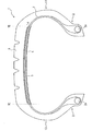
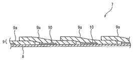
- FIG. 1 is a sectional view of a pneumatic tire according to a first embodiment of the present invention in a tire width direction. Sectional drawing of a tire width direction of a part of puncture prevention member.
- the top view which shows arrangement
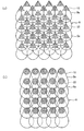
- the top view which shows another embodiment of the protective material of a puncture prevention member.
- the top view which shows another embodiment of the protective material of a puncture prevention member.
- FIG. 6 is a schematic cross-sectional view showing a state immediately before a nail is stuck into the puncture prevention member.
- FIG. 6 is a schematic cross-sectional view showing a state when a nail is stuck in the puncture prevention member.
- Sectional drawing of the tire width direction of a part of puncture prevention material used for the pneumatic tire which concerns on 2nd Embodiment of this invention A tire width direction sectional view of a pneumatic tire concerning a 3rd embodiment of the present invention.
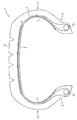
- the tire width direction sectional view of the pneumatic tire concerning a 4th embodiment of the present invention.
- FIG. 1 is a cross-sectional view in the tire width direction of a pneumatic tire 1 according to a first embodiment of the present invention, showing a state in which the pneumatic tire 1 is mounted on an applicable rim, a prescribed internal pressure is filled, and no load is applied.
- the tire width direction cross section is shown.
- the pneumatic tire 1 (hereinafter, also simply referred to as a tire 1) includes a carcass 3 that extends in a toroidal manner on a bead core 2a embedded in a pair of bead portions 2 of a tire body.
- the belt 4 and the tread 5 each including a belt layer of two or more layers (two layers in the illustrated example) are sequentially provided.
- the “applicable rim” is an industrial standard that is effective in regions where tires are produced and used.
- JATMA Joint Automobile Tire Manufacturer's Association
- ETRTO European Tired and STANDARDS MANUAL of Rim Technical Organization
- YEAR BOOK of TRA The Tire and Rim Association, Inc.
- standard rim ETRTO STRUARD MANUAL MANUAL of standard size of ETRTOm urning that will be described in the future.
- TRA YEAR BOOK Design Rim). (That is, the above "rim” includes not only the current size but also a size that may be included in the above industry standard in the future.
- the “size to be described in the future” is ETRTO's STANDARD DSMANUAL 2013 edition.
- the size described as “FUTURE DEVELOPMENTS” can be mentioned in the above), but in the case of a size not described in the above industrial standard, it means a rim having a width corresponding to the bead width of the tire.
- the “specified internal pressure” means an air pressure (maximum air pressure) corresponding to the maximum tire load capacity of the standard such as JATMA in the tire of the applicable size.
- the “specified internal pressure” means an air pressure (maximum air pressure) corresponding to the maximum load capacity specified for each vehicle in which the tire is mounted.
- the “maximum load load” described below is the maximum tire load capacity of the standard such as JATMA in the tire of the applicable size, or, in the case of the size not described in the above industrial standard, the maximum specified for each vehicle to which the tire is mounted. It means the load corresponding to the load capacity.
- the internal structure of the tire is not particularly limited, except for the puncture prevention member that adheres to the inner surface of the tire body described later, and any internal structure of the tire can be used according to the custom.
- a configuration without a bead core may be used, the material and number of carcass plies are not particularly limited, and the number of belt layers is not particularly limited.
- a puncture prevention member 7 is bonded to at least a part of an inner surface 6 of the tire body.
- the puncture prevention member 7 is disposed only on the inner surface 6 of the tire body in the tire width direction region between the tread ends TE of the tread 5 (hereinafter, also referred to as the inner surface of the tread portion). However, it is not arranged in other regions (the inner surface of the sidewall portion and the inner surface of the bead portion).
- the “tread edge” means the outermost edge in the tire width direction of the ground contact surface when the tire is mounted on the applicable rim, filled with the specified internal pressure, and the maximum load is applied.
- the puncture prevention member 7 is bonded to at least a part of the inner surface 6 of the tire main body, and specifically, of the inner surface of the tread portion, both end portions of the inner surface of the tread portion (for example, the peripheral length of the entire inner surface of the tread is equal to the peripheral length). 3% of each area) and not other areas of the inner surface of the tread portion.
- the entire surface of the puncture prevention member 7 is adhered to the inner surface 6 of the tire body, but at least a part of the puncture prevention member 7 is separated from the inner surface 6 of the tire body when the nail penetrates. In any of the above cases, it is possible to obtain the effect of sufficiently dispersing the input by the nail 11 described later.
- the puncture prevention member 7 is adhered to at least a part of the inner surface 6 of the tire body, the input by the nail 11 can be dispersed uniformly.
- FIG. 1 is a cross-sectional view of a portion of the puncture prevention member 7 in the tire width direction
- FIG. 3 is a plan view showing an arrangement of a protective material 9a forming a protective layer 9 of the puncture prevention member 7.
- the puncture prevention member 7 has an internal pressure holding layer 8 and a protective layer 9 which is at least a part of the existing area of the internal pressure holding layer 8 and is arranged on the tire outer surface side of the internal pressure holding layer 8.
- the protective layer 9 is formed of a plurality of sheet-shaped protective materials 9a having a smaller area than the internal pressure holding layer 8 arranged in a plane.
- the description of the internal pressure holding layer 8 is omitted.
- the internal pressure retaining layer 8 has, for example, a thickness of 0.05 mm to 1 mm and has elasticity, and its material is synthetic rubber such as natural rubber, butadiene rubber, styrene butadiene rubber, isoprene rubber, butyl rubber, nitrile rubber. , A styrene-based elastomer, an olefin-based elastomer, an ester-based elastomer, a urethane-based elastomer, a polyamide-based elastomer, or the like, and a blend thereof.
- the protective material 9a has, for example, a thickness of 0.05 mm to 3 mm, and the material thereof can be a non-woven fabric, a film, a fiber reinforced plastic, a rubber or a steel plate, or a combination thereof. As a result, it is possible to easily achieve the weight reduction of the tire 1 and the improvement of the puncture resistance.
- the plurality of protective materials 9a forming the protective layer 9 at least a part of the protective material 9a is arranged so as to partially overlap with the other protective material 9a, and one of the surfaces facing the internal pressure holding layer 8 is disposed. The portion is bonded to the internal pressure holding layer 8 by a bonding means such as an adhesive.
- the adhesive portion 10 of the protective material 9a to the internal pressure holding layer 8 is shown by dots.
- the area of the protective material 9a in plan view is preferably 100 mm 2 to 2000 mm 2 , but can be appropriately designed depending on the material and thickness of the protective material 9a.
- each protective material 9a is formed in a circular shape, and all the protective materials 9a are arranged so as to partially overlap the other protective materials 9a, and A part of the surface facing the internal pressure holding layer 8 is adhered to the internal pressure holding layer 8, specifically, a circular center portion. Further, the protective material 9a of the present embodiment is arranged so as to overlap the other protective material 9a in a non-adhesive region with respect to the internal pressure holding layer 8.
- the puncture prevention member 7 includes a portion in which the protective material 9a is composed of one layer (a portion having a substantially hexagonal shape in a transmission plan view) and a portion made of two layers (a substantially square shape in a transmission plane view). A portion having a shape) and a portion having three layers (a portion having a substantially triangular shape in a transmission plane view).
- the position of the adhesive portion 10 of each protective member 9a is not limited to the circular central portion, and may be the peripheral portion thereof.
- the shape of the protective material 9a is not limited to a circular shape, and may have various shapes such as a triangular shape, a polygonal shape such as a quadrangle or a hexagon, an oval shape, or a drop shape in a plan view.
- the protective layer 9 can be formed by combining a plurality of protective materials 9a having different shapes in plan view. Also in this case, it is preferable that at least one protective material 9a is present when the puncture prevention member 7 is viewed in the layer thickness direction.
- FIGS. 4 and 5 another embodiment of the arrangement and shape of the protective material 9 forming the protective layer 9 will be described with reference to FIGS. 4 and 5.
- the protective material 9a is formed in a circular shape in a plan view, and a part of the circular peripheral portion is adhered to the internal pressure holding layer 8 by an adhering means. Further, the protective material 9a is overlapped with the other protective material 9a in the non-adhesive state in the adhesion region to the internal pressure holding layer 8.
- the protective material 9a has a hexagonal shape in a plan view, the central portion thereof is adhered to the internal pressure holding layer 8, and the peripheral portion overlaps with the other protective material 9a.
- the protective material 9a has a hexagonal shape in this manner, the amount of the end material of the protective material 9a generated during manufacturing can be reduced.
- the protective material 9a is formed in a drop shape in plan view.
- One end portion (an upper end portion in the drawing) that is narrow in the drop shape is formed in a substantially triangular shape in a plan view, and this one end portion is bonded to the internal pressure holding layer 8, and the other regions are in a non-bonded state. ..
- a plurality of each protective material 9a is arranged so as to partially overlap the other protective material 9a.
- a plurality of protective materials 9a arranged adjacent to each other in the column direction (horizontal direction in the drawing) and arranged at equal intervals are arranged so as to overlap in the row direction (vertical direction in the drawing), and are adjacent to each other.
- the protective material 9a is formed in a drop shape in plan view.
- One end portion (an upper end portion in the drawing) that is narrow in the drop shape is formed in a curved surface shape with a rounded peripheral edge in a plan view, and this one end portion is bonded to the internal pressure holding layer 8 and the other region is not bonded. It is in a state.
- a plurality of protective materials 9a arranged at equal intervals so as to partially overlap in the column direction are arranged in the same phase so as to overlap in the row direction. As shown in FIGS. 5A and 5B, by forming the protection material 9a in a drop shape, a wide area where the protection material 9a overlaps can be secured.
- FIG. 6A is a schematic cross-sectional view showing a state immediately before a nail is stuck into the puncture prevention member 7, and FIG. 6B is a schematic sectional view showing a state when a nail is stuck into the puncture prevention member 7.
- the protection member 9a can prevent the puncture prevention member 7 from being broken by the tip of the nail 11.
- the present embodiment when viewed in the layer thickness direction, since there is at least one or more protective material 9a, puncture due to the penetration of the nail 11 is always detected at any location on the inner surface of the tread portion. It can be prevented by the protective material 9a.
- the input can be dispersed by the expansion of the internal pressure holding layer 8 with respect to the input by the nail 11. Further, since each protective material 9a is partially adhered to the internal pressure holding layer 8 by the adhesive portion 10, it is possible to secure the degree of freedom of expansion/contraction deformation of the internal pressure holding layer 8. Thereby, the puncture resistance of the tire 1 can be improved.
- FIG. 7 is a cross-sectional view of the puncture prevention material 7 used in the pneumatic tire 1 according to the second embodiment of the present invention. Since the installation area of the puncture prevention material 7 is the same as that of the embodiment shown in FIG. 1, the description thereof is omitted here.
- the puncture prevention member 7 of the present embodiment has an internal pressure holding layer 8 and a protective layer 9 which is at least a part of the area where the internal pressure holding layer 8 is present and which is arranged on the tire outer surface side of the internal pressure holding layer 8.
- the protective layer 9 includes a base material 9b and a plurality of protective materials 9a arranged in a plane shape on the outer side of the base material 9b in the tire radial direction.
- the base material 9b preferably has a sheet shape (including a net shape having a mesh) having a required width and has elasticity.
- the protection material 9a has a smaller area than the base material 9b in a plan view, and at least a part of the protection material 9a among the plurality of protection materials 9a is arranged in a state where a part thereof overlaps with another protection material 9a. A part of the surface facing the base material 9b is adhered to the base material 9b.
- the existing region of the base material 9b can be the same as the existing region of the internal pressure holding layer 9, for example.
- the arrangement of the protective material 9a can be the same as that shown in FIG. 3, for example, and the circular protective material 9a is bonded to the base material 9b via the central adhesive portion 10.
- a plurality of protective materials 9a are arranged so that at least one protective material 9a exists in the layer thickness direction, and the puncture prevention member 7 is preferably covered almost entirely with the plurality of protective materials 9a. ..
- the position of the adhesive portion 10 of each protective member 9a is not limited to the circular central portion, and may be the peripheral portion thereof.
- the shape of the protective material 9a is not limited to a circular shape, and may have various shapes such as a triangular shape, a polygonal shape such as a quadrangle or a hexagon, an oval shape, or a drop shape in a plan view.
- the protective layer 9 can be formed by combining a plurality of protective materials 9a having different shapes in plan view. Also in this case, when the puncture prevention member 7 is viewed in the layer thickness direction, it is preferable that at least one protective material 9a is present when viewed.
- the base material 9b can be, for example, either a woven fabric or a knitted fabric.
- the existing region of the base material 9b can be the same as the existing region of the internal pressure holding layer 9, for example.
- a woven fabric using stretchable polyurethane or polytrimethylene terephthalate, or a knitted fabric using organic fibers used for general industrial products such as polyester and nylon can be used.
- the woven fabric and the knitted fabric forming the base material 9b can be, for example, woven or knitted yarns or cords having a fineness of 10 to 1100 dtex.
- the base material 9b is adhered to at least a partial region of the internal pressure holding layer 8, and for example, the base material 9b and the internal pressure holding layer 8 are overlapped with the adhesion portion of the puncture prevention member 7 to the tire body in the layer thickness direction. Can be adhered to each other and not to other areas.
- the protection layer 9 can prevent the puncture prevention member 7 from being broken by the tip of the nail 11.
- the input can be controlled by the expansion of the internal pressure holding layer 8 with respect to the input by the nail 11.
- the puncture prevention member 7 can be prevented from being broken by the input of the nail 11, and the puncture resistance of the tire can be improved.
- the base material 9b is expanded with respect to the input by the nail 11, the input can be dispersed, and the puncture resistance can be further improved.
- the 100% modulus of the portion having the lowest 100% modulus of the puncture prevention member 7 is M (MPa), and the thickness of the portion of the puncture prevention member 7 is T (mm. )
- the initial rigidity when the nail penetrates is Y (N/mm) and the penetration strength of the portion of the puncture prevention member 7 having the highest penetration strength is S(N)
- the relational expression, S ⁇ 100 ⁇ M It is preferable that ⁇ T+4.5 and Y/(M ⁇ T) ⁇ 2 are satisfied.
- the puncture prevention member 7 that satisfies these relational expressions and is relatively easily stretched as compared with the breaking strength, the input by the nail 11 is sufficiently dispersed, and the puncture prevention member 7 is broken by the input of the nail 11. It is possible to further improve the puncture resistance of the tire 1.
- “100% modulus” means that a dumbbell-shaped No. 3 sample is prepared in accordance with JIS K6251 and a tensile test is performed at room temperature of 23°C and a speed of 500 ⁇ 25 mm/min. Is the tensile stress at 100% elongation.
- “penetration strength” means that a cut sample having a diameter of 80 mm of the puncture prevention member and N100 nail specified in JIS standard is prepared, the cut sample is attached to a pressure resistant chamber, and an internal pressure of 230 kPa is set. In this state, the force is applied to the cut sample by the nail in such a state that the nail penetrates the cut sample or the cut sample breaks.
- the "initial rigidity at the time of nail penetration” means that in the above-mentioned nail penetration test, the horizontal axis represents the amount of nail penetration, and the vertical axis represents the stress-nail penetration amount curve when the force related to the nail is applied. This is the change in the force applied to the nail when it was 0 to 10 mm.
- the puncture prevention member 7 that satisfies the above relational expression can be configured by using the configurations shown in the above-described embodiments and the materials of the members illustrated above.
- the 100% modulus M of the portion having the lowest 100% modulus of the puncture prevention member 7 is preferably 0.1 to 10 MPa.
- the 100% modulus M of the portion having the lowest 100% modulus of the puncture prevention member 7 is preferably 0.2 to 7.0 MPa, and more preferably 0.2 to 3.0 MPa. preferable.
- the penetration strength S is preferably 45 N or more. By setting the penetration strength S to 45 N or more, sufficient strength against external input can be secured and penetration breakage can be prevented. Further, in the present invention, the penetration strength S is preferably 60 N or more. For the same reason, it is possible to secure puncture resistance against a larger input. Further, in the present invention, the nail penetration amount L when the nail penetrates is preferably 20 mm or more. This is because it is possible to sufficiently disperse the input by the nail and improve the puncture resistance. Further, in the present invention, the nail penetration amount L when the nail penetrates is preferably 50 mm or more. For the same reason, it is possible to improve the puncture resistance against a larger input.
- the gas permeability coefficient of the portion having the highest gas permeability coefficient of the puncture prevention member 7 at 60° C. is 6.0 ⁇ 10 ⁇ 10 cc ⁇ cm/cm 2 ⁇ sec ⁇ cmHg or less.
- the effect of holding the internal pressure of the tire can be enhanced.
- FIG. 8 is a tire width direction cross-sectional view of the pneumatic tire 1 according to the third embodiment of the present invention.
- FIG. 8 shows a tire width direction cross section in a state in which the pneumatic tire 1 is mounted on an applicable rim, is filled with a specified internal pressure, and is unloaded.
- the tire 1 shown in FIG. 8 is different from the tire 1 of the embodiment shown in FIG. 1 in the region to which the puncture prevention member 7 is adhered, and specifically, is the inner surface 6 of the tire main body, and It is arranged only on the inner surface of the sidewall portion 12 continuous with the bead portion 2 (of the inner surface of the tire, the inner surface forming the tire radial direction region of the sidewall portion 12).
- the puncture prevention member 7 is adhered to at least a part of the inner surface 6 of the tire body, and specifically, of the inner surface of the sidewall portion 12, both end portions of the inner surface of the sidewall portion 12 (for example, the tire inner surface). 6 regions (each 3% of the peripheral length), but not to other regions on the inner surface of the sidewall portion 12.
- the laminated structure of the puncture prevention member 7 any one of the structures of the above-described first and second embodiments or another embodiment thereof can be adopted.
- the protection layer 9 can protect the puncture prevention member 7 from being broken by the tip of the nail 11. Further, since the internal pressure holding layer 8 is arranged, the input can be dispersed by the expansion of the internal pressure holding layer 8 with respect to the input by the nail 11. As a result, it is possible to suppress breakage of the puncture prevention member 7 due to the input of the nail 11 and improve the puncture resistance of the tire 1. Further, even when a cut occurs due to the sidewall portion 12 colliding with an obstacle such as a curb during traveling of the vehicle, breakage of the puncture prevention member 7 can be suppressed and puncture resistance can be improved.
- FIG. 9 is a tire width direction sectional view of the pneumatic tire 1 according to the fourth embodiment of the present invention.
- FIG. 9 shows a cross section in the tire width direction in a state where the pneumatic tire 1 is mounted on an applicable rim, a specified internal pressure is filled, and no load is applied.
- the tire 1 shown in FIG. 9 is different from the tire 1 of the embodiment shown in FIGS. 1 and 8 in the region where the puncture prevention member 7 is arranged. Specifically, in the tire 1 shown in FIG. 9, the puncture prevention member 7 is arranged on the entire inner surface 6 of the tire body.
- the puncture prevention member 7 is adhered to at least a part of the inner surface 6 of the tire body, and specifically, is adhered only to the inner surface of the bead portion and is adhered to other areas (the inner surface of the tread portion and the sidewall portion 12). Inner surface) is not adhered.
- the laminated structure of the puncture prevention member 7 any one of the structures of the above-described first and second embodiments and another embodiment thereof can be adopted.
- the protection layer 9 can protect the puncture prevention member 7 from being broken by the tip of the nail 11. Further, since the internal pressure holding layer 8 is arranged, the internal pressure holding layer 8 expands with respect to the input by the nail 11, so that the input can be controlled. As a result, it is possible to suppress breakage of the puncture prevention member 7 due to the input of the nail 11 and improve the puncture resistance of the tire 1.
- tires according to the invention example and the comparative example are prototyped and a test for evaluating puncture resistance is performed.
- the tire size of each tire is 195/65R15, and the internal pressure of each tire is 230 kPa.
- the specifications of each tire are shown in Table 1 below together with the evaluation results.
- the puncture prevention member is attached to the entire inner surface of the tire body, and the puncture prevention member is adhered to at least a part of the inner surface of the tire body (near the bead portion).
- a puncture prevention member is arranged on the inner surface. As shown in FIG.
- each puncture prevention member includes an internal pressure holding layer 8, a base material 9b arranged on the tire outer surface side of the internal pressure holding layer 8, and a protective layer 9 having a plurality of circular protective members 9a. , And are configured to have.
- an inner liner made of butyl rubber is arranged on the entire inner surface of the tire body, and in Comparative Example 2, a sealant layer is further arranged on the tire inner side of the inner liner.
Landscapes
- Engineering & Computer Science (AREA)
- Mechanical Engineering (AREA)
- Tires In General (AREA)
Abstract
[要約] [課題]耐パンク性を向上しながら、タイヤの軽量化を図ることができる空気入りタイヤを提供すること。 [解決手段]タイヤ本体の内面の少なくとも一部にパンク防止部材7を接着した空気入りタイヤ1であって、前記パンク防止部材は、内圧保持層8と、該内圧保持層の存在領域の少なくとも一部の領域であって該内圧保持層のタイヤ外表面側に配置された保護層9と、を有し、前記保護層は、前記内圧保持層よりも小面積の複数の保護材9aを面状に有し、前記複数の保護材のうち、少なくとも一部の保護材は、他の保護材と一部で重なった状態で配置され、且つそれぞれ一部で前記内圧保持層に接着されている。 [選択図]図2
Description
本発明は、空気入りタイヤに関する。
従来、空気入りタイヤにおいては、タイヤのパンクに対する種々の対策がなされている。
パンクに対する対策の例として、サイド部に断面三日月形のサイドゴムを配置した、いわゆるサイド部補強型のランフラットタイヤが知られている(例えば、特許文献1)。このランフラットタイヤによれば、タイヤがパンクした後においてもサイドゴムが荷重を肩代わりして走行を続行することができる。
また、パンクに対する対策の他の例として、タイヤの内面側にシーラント剤を塗布した、いわゆるシーラントタイヤが知られている(例えば、特許文献2)。このシーラントタイヤによれば、タイヤに釘が刺さった際にゲル状のシーラント剤が釘に密着するようにまとわりついてシールするため、空気の漏出を防止することができる。更に、刺さった釘が抜けた後もトレッド部の貫通孔にシーラント剤が引きずり込まれてシールするため空気漏れを起こすことがない。
しかしながら、ランフラットタイヤでは、高重量・高剛性のサイドゴムを配置することにより、乗り心地性の悪化や重量増大を招いてしまうという問題があった。また、シーラントタイヤでは、タイヤの回転で発生する遠心力によりゲル状のシーラント剤がトレッド部に寄ってしまい、トレッド部よりもタイヤ幅方向外側のショルダー部やサイドウォール部での耐パンク性が低下してしまうという問題があった。
本発明は、上記課題に鑑みてなされたものであり、耐パンク性を向上しながら、タイヤの軽量化を図ることができる空気入りタイヤを提供することにある。
上記目的を達成するために、請求項1に係る空気入りタイヤは、タイヤ本体の内面の少なくとも一部にパンク防止部材を接着した空気入りタイヤであって、前記パンク防止部材は、内圧保持層と、該内圧保持層の存在領域の少なくとも一部の領域であって該内圧保持層のタイヤ外表面側に配置された保護層と、を有し、前記保護層は、前記内圧保持層よりも小面積の複数の保護材を面状に有し、前記複数の保護材のうち、少なくとも一部の保護材は、他の保護材と一部で重なった状態で配置され、且つそれぞれ一部で前記内圧保持層に接着されていることを特徴とする。
この構成によれば、例えば、釘の先端等の異物の進入によってタイヤがパンクするのを保護材によって防止し、その内側の内圧保持層によりタイヤ内の空気圧を保持することができるので、耐パンク性を向上することができる。また、高重量の補強材を用いることなく、内圧保持層と保護層とからなるパンク防止部材によって耐パンク性を確保することができるので、タイヤの軽量化を図ることができる。
また、請求項2に係る空気入りタイヤは、タイヤ本体の内面の少なくとも一部にパンク防止部材を接着した空気入りタイヤであって、前記パンク防止部材は、内圧保持層と、該内圧保持層の存在領域の少なくとも一部の領域であって該内圧保持層のタイヤ外表面側に配置された保護層と、を有し、前記保護層は、基材と、該基材のタイヤ半径方向外側に面状に配置した該基材よりも小面積の複数の保護材と、を有し、前記複数の保護材うち、少なくとも一部の保護材は、他の保護材と一部で重なった状態で配置され、且つそれぞれ一部で前記基材に接着されていることを特徴とする。
この構成によれば、例えば、釘の先端等の異物の進入によってタイヤがパンクするのを保護材によって防止し、その内側の内圧保持層によりタイヤ内の空気圧を保持することができるので、耐パンク性を向上することができる。また、保護材が伸縮性を有する基材に接着されているので、この基材の存在により、釘などの異物の進入時に内圧保持層に入力される力を分散させることができる。また、高重量の補強材を用いることなく、内圧保持層と保護層とからなるパンク防止部材によって耐パンク性を確保することができるので、タイヤの軽量化を図ることができる。
また、請求項3に記載の発明は、請求項2に記載の空気入りタイヤにおいて、前記基材は、織物又は編み物のいずれかであることを特徴とする。
この構成によれば、軽量な様々な種類の中からより適する基材を選択することができ、軽量化しながら耐パンク性を向上させることができる。
また、請求項4に記載の発明は、請求項1~3のいずれか1項に記載の空気入りタイヤにおいて、前記保護層において前記保護材は、層厚方向で前記保護材が少なくとも1つ存在するように複数配列されていることを特徴とする。
この構成によれば、保護層のいずれの箇所においても異物の進入によるパンクを常に何れかの保護材により防止することができるので、耐パンク性をより向上することができる。
また、請求項5に記載の発明は、請求項1~4のいずれか1項に記載の空気入りタイヤにおいて、
前記保護材は、不織布、フィルム、繊維強化プラスチック若しくはゴム、又はこれらの組み合わせで形成されていることを特徴とする。
前記保護材は、不織布、フィルム、繊維強化プラスチック若しくはゴム、又はこれらの組み合わせで形成されていることを特徴とする。
この構成によれば、軽量化と耐パンク性の向上を容易に達成することができる。
本発明の空気入りタイヤによれば、内圧保持層と保護層とからなるパンク防止部材により耐パンク性を向上しながら、タイヤの軽量化を図ることができる。
以下、本発明の実施形態について、図面を参照して詳細に例示説明する。
(第1実施形態)
図1は、本発明の第1実施形態に係る空気入りタイヤ1のタイヤ幅方向断面図であり、空気入りタイヤ1を適用リムに装着し、規定内圧を充填し、無負荷とした状態でのタイヤ幅方向断面を示している。この空気入りタイヤ1(以下、単にタイヤ1とも称する)は、タイヤ本体の一対のビード部2に埋設されたビードコア2aにトロイダル状に跨るカーカス3を備え、カーカス3のタイヤ径方向外側に、1層以上(図示例では2層)のベルト層からなるベルト4とトレッド5とを順に有している。
図1は、本発明の第1実施形態に係る空気入りタイヤ1のタイヤ幅方向断面図であり、空気入りタイヤ1を適用リムに装着し、規定内圧を充填し、無負荷とした状態でのタイヤ幅方向断面を示している。この空気入りタイヤ1(以下、単にタイヤ1とも称する)は、タイヤ本体の一対のビード部2に埋設されたビードコア2aにトロイダル状に跨るカーカス3を備え、カーカス3のタイヤ径方向外側に、1層以上(図示例では2層)のベルト層からなるベルト4とトレッド5とを順に有している。
ここで、「適用リム」とは、タイヤが生産され、使用される地域に有効な産業規格であって、日本ではJATMA(日本自動車タイヤ協会)のJATMA YEAR BOOK、欧州ではETRTO(The European Tyre and Rim Technical Organisation)のSTANDARDS MANUAL、米国ではTRA(The Tire and Rim Association, Inc.)のYEAR BOOK等に記載されている、または将来的に記載される適用サイズにおける標準リム(ETRTOのSTANDARDS MANUALではMeasuringRim、TRAのYEAR BOOKではDesign Rim)を指す。(すなわち、上記の「リム」には、現行サイズに加えて将来的に上記産業規格に含まれ得るサイズも含む。「将来的に記載されるサイズ」の例としては、ETRTOのSTANDARDSMANUAL 2013年度版において「FUTURE DEVELOPMENTS」として記載されているサイズを挙げることができる。)が、上記産業規格に記載のないサイズの場合は、タイヤのビード幅に対応した幅のリムをいう。また、「規定内圧」は、適用サイズのタイヤにおける上記JATMA等の規格のタイヤ最大負荷能力に対応する空気圧(最高空気圧)をいう。なお、上記産業規格に記載のないサイズの場合は、「規定内圧」は、タイヤを装着する車両ごとに規定される最大負荷能力に対応する空気圧(最高空気圧)をいうものとする。後述の「最大負荷荷重」は、適用サイズのタイヤにおける上記JATMA等の規格のタイヤ最大負荷能力、又は、上記産業規格に記載のないサイズの場合は、タイヤを装着する車両ごとに規定される最大負荷能力に対応する荷重を意味する。
なお、タイヤの内部構造については、後述のタイヤ本体の内面に接着するパンク防止部材を除いては、特に限定されることはなく、慣例に従い、任意のタイヤの内部構造とすることができる。例えば、ビードコアを有しない構成とすることもでき、カーカスプライの材質や枚数も特に限定されず、ベルト層の層数も特に限定されない。
図1に示すように、本実施形態のタイヤ1は、タイヤ本体の内面6の少なくとも一部にパンク防止部材7が接着されている。本実施形態においてパンク防止部材7は、タイヤ本体の内面6のうち、トレッド5のトレッド端TEの間のタイヤ幅方向領域のタイヤ本体の内面6(以下、トレッド部内面とも称する)のみに配置されており、他の領域(サイドウォール部内面やビード部内面)には配置されていない。ここで、「トレッド端」とは、タイヤを適用リムに装着し、規定内圧を充填し、最大負荷荷重を負荷した際の接地面のタイヤ幅方向最外側端をいうものとする。
パンク防止部材7は、タイヤ本体の内面6の少なくとも一部の領域と接着しており、具体的には、トレッド部内面のうち、トレッド部内面の両端部(例えばトレッド内面全面のペリフェリ長さの3%ずつの領域)のみと接着し、トレッド部内面の他の領域とは接着していない。一方で、本発明では、パンク防止部材7の全面がタイヤ本体の内面6と接着しつつも、パンク防止部材7の少なくとも一部が、釘貫入時に、タイヤ本体の内面6から離間するように構成されていてもよく、上記のいずれの場合も、後述する釘11による入力を十分に分散させる効果を得ることができる。なお、パンク防止部材7を、タイヤ本体の内面6の少なくとも一部の領域と接着させた場合は、釘11による入力を均一に分散させることができる。
図1ではパンク防止部材7の記載を簡略化して示しており、その詳細は、以下、図2及び図3を参照して説明する。図2はパンク防止部材7の一部のタイヤ幅方向の断面図であり、図3はパンク防止部材7の保護層9を形成する保護材9aの配置を示す平面図である。
パンク防止部材7は、内圧保持層8と、内圧保持層8の存在領域の少なくとも一部の領域であって、内圧保持層8のタイヤ外表面側に配置された保護層9とを有する。保護層9は、面状に配置した内圧保持層8よりも小面積の複数のシート状の保護材9aによって形成されている。なお、図3及び後述する図4及び図5では、内圧保持層8の記載を省略している。
内圧保持層8は、例えば、厚さが0.05mm~1mmであって伸縮性を有し、その材料は、天然ゴム、ブタジエンゴム、スチレンブタジエンゴム、イソプレンゴム、ブチルゴム、ニトリルゴム等の合成ゴム、スチレン系エラストマー、オレフィン系エラストマー、エステル系エラストマー、ウレタン系エラストマー、ポリアミド系エラストマー等の熱可塑性エラストマー及びそれらのブレンドから任意に選択することができる。
保護材9aは、例えば、厚さが0.05mm~3mmであって、その材料は、不織布、フィルム、繊維強化プラスチック、ゴム若しくは鋼板、又はそれらを組み合わせたものとすることができる。これにより、タイヤ1の軽量化と耐パンク性の向上を容易に達成することができる。保護層9を形成する複数の保護材9aのうち、少なくとも一部の保護材9aは、他の保護材9aと一部が重なった状態で配置され、且つ内圧保持層8と対向する面の一部が、接着剤等の接着手段によって内圧保持層8に接着されている。図示例では、保護材9aの内圧保持層8に対する接着部10をドットで示している。平面視で保護材9aの面積は、100mm2~2000mm2であることが好ましいが、保護材9aの素材、厚さによって適宜設計できる。
本実施形態では、図3に示すように、各保護材9aが円形に形成されており、全ての保護材9aが、それぞれ、他の保護材9aと一部が重なった状態で配列され、且つ内圧保持層8との対向面の一部、具体的には円形の中央部で内圧保持層8に接着されている。さらに、本実施形態の保護材9aは、内圧保持層8に対する非接着領域で、他の保護材9aと重なるように配置されている。
また、保護層9では、層厚方向で保護材9aが少なくとも1つ存在するように保護材9aが複数配列され、パンク防止部材7は、ほぼ全域が複数の保護材9aで覆われていることが好ましい。本実施形態では図3に示すように、パンク防止部材7が、保護材9aが一層からなる部分(透過平面視で略六角形状の部分)と、2層からなる部分(透過平面視で略四角形状の部分)と、3層からなる部分(透過平面視で略三角形状の部分)とを有している。
なお、各保護材9aの接着部10の位置は、円形状の中央部に限られず、その周縁部であってもよい。さらに、保護材9aの形状は円形状に限られず、平面視で三角形、四角形若しくは六角形等の多角形状、楕円形状、又は雫型形状等、様々な形状とすることができる。さらに、平面視形状の異なる複数の保護材9aを組み合わせて、保護層9を形成することができる。この場合においても、パンク防止部材7を層厚方向で見たときに、保護材9aが少なくとも1つ以上存在するように構成されていることが好ましい。以下、図4及び図5を参照して、保護層9を形成する保護材9の配置や形状の別の実施形態について説明する。
図4(a)に示す例では、保護材9aが平面視で円形に形成されており、円形の周縁部の一部が接着手段により内圧保持層8に接着されている。さらに、保護材9aは、内圧保持層8に対する接着領域において、他の保護材9aと非接着状態で重なっている。
図4(b)に示す例では、保護材9aが平面視で六角形状であって、その中央部が内圧保持層8に接着され、周縁部が他の保護材9aと重なっている。このように保護材9aを六角形状とした場合には、製造時に発生する保護材9aの端材の量を低減することができる。
図5(a)に示す例では、保護材9aが平面視で雫型に形成されている。雫型形状において幅細となる一端部(図示の上端部)は平面視で略三角形状に形成され、この一端部が内圧保持層8に接着され、他の領域は非接着状態となっている。各保護材9aは、他の保護材9aと一部が重なるように複数配列されている。具体的には、保護材9aを列方向(図示の横方向)に隣接させて等間隔に並べて配列したものを行方向(図示の縦方向)で重なるように複数行配置しており、隣り合う行の間で、列方向に位相を上記間隔の半分だけずらして配置している。図5(b)に示す例では、保護材9aが平面視で雫型に形成されている。雫型形状において幅細となる一端部(図示の上端部)は平面視で周縁が丸みを帯びた曲面形状に形成され、この一端部が内圧保持層8に接着され、他の領域は非接着状態となっている。本実施形態では、保護材9aを列方向に一部が重なるように等間隔に並べて配列したものを行方向で重なるように同位相で複数行配置している。図5(a)及び(b)に示すように、保護材9aを雫型にすることで、保護材9aが重なる領域を広く確保することができる。
次に、本実施形態の作用効果について説明する。
図6Aはパンク防止部材7に釘が刺さる直前の様子を示す模式的な断面図であり、図6Bはパンク防止部材7に釘が刺さった際の様子を示す模式的な断面図である。本実施形態のタイヤ1によれば、トレッド部に釘11が刺さる場合に、保護材9aにより釘11の先端によってパンク防止部材7が破断するのを防止することができる。ここで、本実施形態では、層厚方向で見たときに、保護材9aが少なくとも1つ以上存在しているため、トレッド部内面のいずれの箇所において釘11の進入によるパンクを常にいずれかの保護材9aにより防止することができる。また、釘11による入力に対して内圧保持層8が伸びることにより該入力を分散させることができる。また、各保護材9aは接着部10により内圧保持層8に対して部分的に接着されているため、内圧保持層8の伸縮変形の自由度を確保することができる。これにより、タイヤ1の耐パンク性を向上させることができる。
(第2実施形態)
図7は、本発明の第2実施形態に係る空気入りタイヤ1に用いられるパンク防止材7の断面図である。パンク防止材7の設置領域は、図1に示す実施形態と同様であるため、ここでは説明を省略する。本実施形態のパンク防止部材7は、内圧保持層8と、内圧保持層8の存在領域の少なくとも一部であって内圧保持層8のタイヤ外表面側に配置される保護層9と、を有し、保護層9は、基材9bと、基材9bのタイヤ半径方向外側に面状に配置した複数の保護材9aとを有する。基材9bは、所要の広さを有するシート状(網目を有するネット状も含む)であって伸縮性を有することが好ましい。保護材9aは、平面視で基材9bよりも小面積であり、複数の保護材9aのうち、少なくとも一部の保護材9aは、他の保護材9aと一部が重なった状態で配置され、且つ基材9bとの対向面の一部が基材9bに接着されている。基材9bの存在領域は、例えば、内圧保持層9の存在領域と同じとすることができる。保護材9aの配置は、例えば、図3に示す配置と同一のものとすることができ、円形の保護材9aは、中央の接着部10を介して基材9bに接着される。保護層9では、層厚方向で保護材9aが少なくとも1つ存在するように保護材9aが複数配列され、パンク防止部材7は、ほぼ全域が複数の保護材9aで覆われていることが好ましい。
図7は、本発明の第2実施形態に係る空気入りタイヤ1に用いられるパンク防止材7の断面図である。パンク防止材7の設置領域は、図1に示す実施形態と同様であるため、ここでは説明を省略する。本実施形態のパンク防止部材7は、内圧保持層8と、内圧保持層8の存在領域の少なくとも一部であって内圧保持層8のタイヤ外表面側に配置される保護層9と、を有し、保護層9は、基材9bと、基材9bのタイヤ半径方向外側に面状に配置した複数の保護材9aとを有する。基材9bは、所要の広さを有するシート状(網目を有するネット状も含む)であって伸縮性を有することが好ましい。保護材9aは、平面視で基材9bよりも小面積であり、複数の保護材9aのうち、少なくとも一部の保護材9aは、他の保護材9aと一部が重なった状態で配置され、且つ基材9bとの対向面の一部が基材9bに接着されている。基材9bの存在領域は、例えば、内圧保持層9の存在領域と同じとすることができる。保護材9aの配置は、例えば、図3に示す配置と同一のものとすることができ、円形の保護材9aは、中央の接着部10を介して基材9bに接着される。保護層9では、層厚方向で保護材9aが少なくとも1つ存在するように保護材9aが複数配列され、パンク防止部材7は、ほぼ全域が複数の保護材9aで覆われていることが好ましい。
なお、各保護材9aの接着部10の位置は、円形状の中央部に限られず、その周縁部であってもよい。さらに、保護材9aの形状は円形状に限られず、平面視で三角形、四角形若しくは六角形等の多角形状、楕円形状、又は雫型形状等、様々な形状とすることができる。さらに、平面視形状の異なる複数の保護材9aを組み合わせて、保護層9を形成することができる。この場合においても、パンク防止部材7を層厚方向で見たときに、見たときに、保護材9aが少なくとも1つ以上存在するように構成されていることが好ましい。
基材9bは、例えば、織物又は編物のいずれかとすることができる。基材9bの存在領域は、例えば、内圧保持層9の存在領域と同じとすることができる。基材9bは、例えば、伸縮性のあるポリウレタンやポリトリメチレンテレフタレートを用いた織物や、ポリエステルやナイロンといった一般工業製品に用いられる有機繊維を用いた編み物を用いることができる。ただし、これらは例示であり、素材は特に限定されない。なお、基材9bを構成する織物及び編み物は、例えば、繊度10~1100dtexの糸又はコードを製織したもの又は編んだものとすることができる。
基材9bは、内圧保持層8の少なくとも一部の領域と接着しており、例えば、パンク防止部材7のタイヤ本体に対する接着部と層厚方向で重なる領域で基材9bと内圧保持層8とが接着し、他の領域では接着していない構成とすることができる。
第2実施形態のパンク防止部材7を備えたタイヤ1では、タイヤ1に釘11が刺さる場合に、保護層9により釘11の先端によってパンク防止部材7が破断するのを防止することができる。また、釘11による入力に対して内圧保持層8が伸びることにより該入力をいなすことができる。これにより、釘11の入力によるパンク防止部材7の破断を抑制して、タイヤの耐パンク性を向上させることができる。さらに、釘11による入力に対して基材9bが伸びることにより該入力を分散させることができ、耐パンク性をより向上させることができる。
上述した第1及び第2実施形態においては、パンク防止部材7の最も100%モジュラスが低い部分の該100%モジュラスをM(MPa)とし、パンク防止部材7の該部分の厚さをT(mm)とし、釘貫入時の初期剛性をY(N/mm)とし、パンク防止部材7の最も貫通強度が高い部分の該貫通強度をS(N)とするとき、関係式、S≧100×M×T+4.5、且つ、Y/(M×T)≧2を満たすことが好ましい。これらの関係式を満たす、破断強度に比して相対的に伸びやすいパンク防止部材7を配置することにより、釘11による入力を十分に分散させて、釘11の入力によるパンク防止部材7の破断を抑制して、タイヤ1の耐パンク性をさらに向上させることができる。
なお、本明細書において、「100%モジュラス」とは、JIS K6251に準拠して、ダンベル状3号形サンプルを用意し、室温23℃、速度500±25mm/minの条件下で引張試験を行って測定した、100%伸長時の引張応力である。本明細書において、「貫通強度」とは、JIS規格で規定されているN100釘と、上記パンク防止部材の直径80mmからなるカットサンプルを用意し、カットサンプルを耐圧性チャンバーに取り付け、230kPaの内圧をかけた状態において、釘によりカットサンプルに力をかけていき、カットサンプルを釘が貫通するか、もしくは、カットサンプルが破断するときに釘にかかる力をいうものとする。なお、釘を全て貫入しても破断がない場合には、そのときに釘にかかる力をいうものとする。また、「釘貫入時の初期剛性」とは、上記釘刺し試験において、横軸に釘貫入量、縦軸に釘に係る力を取った時の応力-釘貫入量曲線の釘貫入量が3.0~10mmの時に釘に係る力の変化を取ったものである。
例として、上述した各実施形態に示した構成及び上記で例示した各部材の材料を用いることにより、上記の関係式を満たす、パンク防止部材7を構成することができる。
また、本発明では、パンク防止部材7の最も100%モジュラスが低い部分の該100%モジュラスMは、0.1~10MPaであることが好ましい。上記100%モジュラスMを、0.1MPa以上とすることにより、部材としての製造作業性を担保することができ、一方で、上記100%モジュラスMを、10MPa以下とすることにより、耐パンク性をより一層向上させることができるからである。同様の理由により、パンク防止部材7の最も100%モジュラスが低い部分の該100%モジュラスMは、0.2~7.0MPaであることが好ましく、0.2~3.0MPaであることがさらに好ましい。
また、本発明では、貫通強度Sは、45N以上であることが好ましい。貫通強度Sを45N以上とすることにより、外的入力に対し十分な強度を確保して貫通破断を防止することができるからである。また、本発明では、貫通強度Sは、60N以上であることが好ましい。同様の理由により、より大きな入力に対して、耐パンク性を確保することができるからである。また、本発明では、釘貫通時の釘貫入量Lは、20mm以上であることが好ましい。釘による入力を十分に分散させて、耐パンク性を向上させることができるからである。また、本発明では、釘貫通時の釘貫入量Lは、50mm以上であることが好ましい。同様の理由により、より大きな入力に対して、耐パンク性を向上させることができるからである。ここで、「釘貫通時の釘貫入量」とは、カットサンプルを釘が貫通する、もしくは、カットサンプルが破断するときの釘の貫入量である。なお、釘を全て貫入しても破断がない場合は、L=80mmとする。
また、本発明においては、60℃における、パンク防止部材7の最もガス透過係数が高い部分の該ガス透過係数が、6.0×10⁻¹⁰ cc・cm/cm2・sec・cmHg以下であることが好ましい。タイヤの内圧を保持する効果を高めることができるからである。
(第3実施形態)
図8は、本発明の第3実施形態にかかる空気入りタイヤ1のタイヤ幅方向断面図である。図8は、空気入りタイヤ1を適用リムに装着し、規定内圧を充填し、無負荷とした状態でのタイヤ幅方向断面を示している。図8に示すタイヤ1は、パンク防止部材7が接着されている領域が、図1に示す実施形態のタイヤ1と異なっており、具体的には、タイヤ本体の内面6であって、一対のビード部2に連なるサイドウォール部12の内面(タイヤ内面のうち、サイドウォール部12のタイヤ径方向領域をなす内面)のみに配置されている。パンク防止部材7は、タイヤ本体の内面6の少なくとも一部の領域と接着しており、具体的には、サイドウォール部12の内面のうち、サイドウォール部12の内面の両端部(例えばタイヤ内面6全面のペリフェリ長さの3%ずつの領域)のみと接着し、サイドウォール部12の内面の他の領域とは接着していない。なお、パンク防止部材7の積層構造は、上述した第1及び第2実施形態やその別の実施形態の構造のいずれかを採用することができる。
図8は、本発明の第3実施形態にかかる空気入りタイヤ1のタイヤ幅方向断面図である。図8は、空気入りタイヤ1を適用リムに装着し、規定内圧を充填し、無負荷とした状態でのタイヤ幅方向断面を示している。図8に示すタイヤ1は、パンク防止部材7が接着されている領域が、図1に示す実施形態のタイヤ1と異なっており、具体的には、タイヤ本体の内面6であって、一対のビード部2に連なるサイドウォール部12の内面(タイヤ内面のうち、サイドウォール部12のタイヤ径方向領域をなす内面)のみに配置されている。パンク防止部材7は、タイヤ本体の内面6の少なくとも一部の領域と接着しており、具体的には、サイドウォール部12の内面のうち、サイドウォール部12の内面の両端部(例えばタイヤ内面6全面のペリフェリ長さの3%ずつの領域)のみと接着し、サイドウォール部12の内面の他の領域とは接着していない。なお、パンク防止部材7の積層構造は、上述した第1及び第2実施形態やその別の実施形態の構造のいずれかを採用することができる。
第3実施形態のタイヤ1では、サイドウォール部に釘11が刺さる場合、保護層9により釘11の先端によってパンク防止部材7が破断するのを保護することができる。また、内圧保持層8を配置しているため、釘11による入力に対して内圧保持層8が伸びることにより該入力を分散させることができる。これにより、釘11の入力によるパンク防止部材7の破断を抑制して、タイヤ1の耐パンク性を向上させることができる。また、車両走行時にサイドウォール部12が縁石等の障害物と衝突することによるカットが生じた場合においてもパンク防止部材7の破断を抑制して、耐パンク性を向上させることができる。
(第4実施形態)
図9は、本発明の第4実施形態に係る空気入りタイヤ1のタイヤ幅方向断面図である。図9は、空気入りタイヤ1を適用リムに装着し、規定内圧を充填し、無負荷とした状態でのタイヤ幅方向断面を示している。図9に示すタイヤ1は、パンク防止部材7が配置されている領域が、図1、図8に示す実施形態のタイヤ1と異なっている。具体的には、図9に示すタイヤ1では、タイヤ本体の内面6全面にパンク防止部材7が配置されている。また、パンク防止部材7は、タイヤ本体の内面6の少なくとも一部の領域と接着しており、具体的には、ビード部内面のみと接着し、他の領域(トレッド部内面やサイドウォール部12の内面)とは接着していない。なお、パンク防止部材7の積層構造は、上述した第1及び第2実施形態やその別の実施形態の構造のいずれかを採用することができる。
図9は、本発明の第4実施形態に係る空気入りタイヤ1のタイヤ幅方向断面図である。図9は、空気入りタイヤ1を適用リムに装着し、規定内圧を充填し、無負荷とした状態でのタイヤ幅方向断面を示している。図9に示すタイヤ1は、パンク防止部材7が配置されている領域が、図1、図8に示す実施形態のタイヤ1と異なっている。具体的には、図9に示すタイヤ1では、タイヤ本体の内面6全面にパンク防止部材7が配置されている。また、パンク防止部材7は、タイヤ本体の内面6の少なくとも一部の領域と接着しており、具体的には、ビード部内面のみと接着し、他の領域(トレッド部内面やサイドウォール部12の内面)とは接着していない。なお、パンク防止部材7の積層構造は、上述した第1及び第2実施形態やその別の実施形態の構造のいずれかを採用することができる。
第4実施形態のタイヤ1では、タイヤ1に釘11が刺さる場合、保護層9により釘11の先端によってパンク防止部材7が破断するのを保護することができる。また、内圧保持層8を配置しているため、釘11による入力に対して内圧保持層8が伸びることにより該入力をいなすことができる。これにより、釘11の入力によるパンク防止部材7の破断を抑制して、タイヤ1の耐パンク性を向上させることができる。
本発明の効果を確かめるため、発明例及び比較例にかかるタイヤを試作して、耐パンク性を評価する試験を行っている。各タイヤのタイヤサイズは、195/65R15とし、各タイヤの内圧は230kPaとしている。各タイヤの諸元は、評価結果と共に以下の表1に示している。発明例においては、図9に示すようにパンク防止部材をタイヤ本体の内面全面に装着し、タイヤ本体の内面の少なくとも一部(ビード部付近)にパンク防止部材を接着することで、タイヤ本体の内面にパンク防止部材を配置している。各パンク防止部材は、図7に示すように、内圧保持層8と、該内圧保持層8のタイヤ外表面側に配置された基材9b及び複数の円形の保護材9aを有する保護層9と、を有する構成としている。比較例1では、タイヤ本体の内面全面にブチルゴムからなるインナーライナーを配置し、比較例2では、さらに、インナーライナーのタイヤ内部側にシーラント層を配置している。
<耐パンク性>
発明例及び比較例のタイヤに対し、タイヤの外面からN100釘を20mm釘の先端が出るように押し込み、該釘を引き抜いた後のエア漏れ性を評価している。また、発明例及び比較例のタイヤについて、トレッド部のタイヤ幅方向のセンター部に釘を刺した場合と、バットレス部(トレッド部からサイドウォール部への遷移域)に釘を刺した場合のそれぞれについて評価している。引き抜き後24時間後のエア保持率100を良、99以下を不可としている。
発明例及び比較例のタイヤに対し、タイヤの外面からN100釘を20mm釘の先端が出るように押し込み、該釘を引き抜いた後のエア漏れ性を評価している。また、発明例及び比較例のタイヤについて、トレッド部のタイヤ幅方向のセンター部に釘を刺した場合と、バットレス部(トレッド部からサイドウォール部への遷移域)に釘を刺した場合のそれぞれについて評価している。引き抜き後24時間後のエア保持率100を良、99以下を不可としている。
各試験の評価結果を以下の表1に示している。
<重量>
各タイヤの重量を計測して、評価を行った。評価結果は、比較例1を100とした時の相対値で指数評価し、値が小さい方が軽量であることを示している。各タイヤの評価結果を以下の表1に示している。
各タイヤの重量を計測して、評価を行った。評価結果は、比較例1を100とした時の相対値で指数評価し、値が小さい方が軽量であることを示している。各タイヤの評価結果を以下の表1に示している。

表1に示すように、発明例にかかるタイヤは、比較例1及び比較例2と比較して、耐パンク性に優れていることがわかる。また、シーラント層を配置した比較例2と比較して、耐パンク性を向上しながら重量を軽量化することができることがわかる。
なお、本発明は上述した実施の形態に限定されるものではなく、発明の趣旨を逸脱しない範囲で種々の変更が可能である。
1 空気入りタイヤ
2 ビード部
2a ビードコア
3 カーカス
4 ベルト
5 トレッド
6 内面
7 パンク防止材
8 内圧保持層
9 保護層
9a 保護材
9b 基材
10 接着部
11 釘
12 サイドウォール部
TE トレッド
2 ビード部
2a ビードコア
3 カーカス
4 ベルト
5 トレッド
6 内面
7 パンク防止材
8 内圧保持層
9 保護層
9a 保護材
9b 基材
10 接着部
11 釘
12 サイドウォール部
TE トレッド
Claims (5)
- タイヤ本体の内面の少なくとも一部にパンク防止部材を接着した空気入りタイヤであって、
前記パンク防止部材は、内圧保持層と、該内圧保持層の存在領域の少なくとも一部の領域であって該内圧保持層のタイヤ外表面側に配置された保護層と、を有し、
前記保護層は、前記内圧保持層よりも小面積の複数の保護材を面状に有し、
前記複数の保護材のうち、少なくとも一部の保護材は、他の保護材と一部で重なった状態で配置され、且つそれぞれ一部で前記内圧保持層に接着されていることを特徴とする空気入りタイヤ。 - タイヤ本体の内面の少なくとも一部にパンク防止部材を接着した空気入りタイヤであって、
前記パンク防止部材は、内圧保持層と、該内圧保持層の存在領域の少なくとも一部の領域であって該内圧保持層のタイヤ外表面側に配置された保護層と、を有し、
前記保護層は、基材と、該基材のタイヤ半径方向外側に面状に配置した該基材よりも小面積の複数の保護材と、を有し、
前記複数の保護材うち、少なくとも一部の保護材は、他の保護材と一部で重なった状態で配置され、且つそれぞれ一部で前記基材に接着されていることを特徴とする空気入りタイヤ。 - 前記基材は、織物又は編み物のいずれかであることを特徴とする請求項2に記載の空気入りタイヤ。
- 前記保護層において前記保護材は、層厚方向で前記保護材が少なくとも1つ存在するように複数配列されていることを特徴とする請求項1~3のいずれか1項に記載の空気入りタイヤ。
- 前記保護材は、不織布、フィルム、繊維強化プラスチック若しくはゴム、又はこれらの組み合わせで形成されていることを特徴とする請求項1~4のいずれか1項に記載の空気入りタイヤ。
Priority Applications (1)
| Application Number | Priority Date | Filing Date | Title |
|---|---|---|---|
| JP2020557772A JPWO2020111112A1 (ja) | 2018-11-30 | 2019-11-27 | 空気入りタイヤ |
Applications Claiming Priority (2)
| Application Number | Priority Date | Filing Date | Title |
|---|---|---|---|
| JP2018224959 | 2018-11-30 | ||
| JP2018-224959 | 2018-11-30 |
Publications (1)
| Publication Number | Publication Date |
|---|---|
| WO2020111112A1 true WO2020111112A1 (ja) | 2020-06-04 |
Family
ID=70853753
Family Applications (1)
| Application Number | Title | Priority Date | Filing Date |
|---|---|---|---|
| PCT/JP2019/046345 Ceased WO2020111112A1 (ja) | 2018-11-30 | 2019-11-27 | 空気入りタイヤ |
Country Status (2)
| Country | Link |
|---|---|
| JP (1) | JPWO2020111112A1 (ja) |
| WO (1) | WO2020111112A1 (ja) |
Citations (4)
| Publication number | Priority date | Publication date | Assignee | Title |
|---|---|---|---|---|
| JPS5364404U (ja) * | 1976-11-01 | 1978-05-31 | ||
| JPS60154904A (ja) * | 1984-01-24 | 1985-08-14 | Shiraishi Komuten:Kk | 自動車タイヤ |
| JPH04212607A (ja) * | 1990-01-22 | 1992-08-04 | Ki Won Song | 車輪用タイヤのパンク防止具 |
| JP2002283817A (ja) * | 2001-03-27 | 2002-10-03 | Yokohama Rubber Co Ltd:The | 空気入りタイヤ |
-
2019
- 2019-11-27 WO PCT/JP2019/046345 patent/WO2020111112A1/ja not_active Ceased
- 2019-11-27 JP JP2020557772A patent/JPWO2020111112A1/ja active Pending
Patent Citations (4)
| Publication number | Priority date | Publication date | Assignee | Title |
|---|---|---|---|---|
| JPS5364404U (ja) * | 1976-11-01 | 1978-05-31 | ||
| JPS60154904A (ja) * | 1984-01-24 | 1985-08-14 | Shiraishi Komuten:Kk | 自動車タイヤ |
| JPH04212607A (ja) * | 1990-01-22 | 1992-08-04 | Ki Won Song | 車輪用タイヤのパンク防止具 |
| JP2002283817A (ja) * | 2001-03-27 | 2002-10-03 | Yokohama Rubber Co Ltd:The | 空気入りタイヤ |
Also Published As
| Publication number | Publication date |
|---|---|
| JPWO2020111112A1 (ja) | 2021-11-11 |
Similar Documents
| Publication | Publication Date | Title |
|---|---|---|
| JP6904355B2 (ja) | ランフラットタイヤ | |
| US7165587B2 (en) | Toric reinforced air bag for safety tire and method of producing the same as well as method of producing shaped body for reinforcing layer | |
| AU2012218857B2 (en) | Rubber patch for repairing radial tires, method for repairing radial tires using same, and repaired radial tire | |
| JP4663211B2 (ja) | 安全タイヤ用空気のう | |
| EP2384285B1 (en) | Tire sidewall shear decoupling layer | |
| JP6927221B2 (ja) | 空気入りタイヤ | |
| EP2527162A1 (en) | Carcass ply structure for a pneumatic tire | |
| JP4604026B2 (ja) | 安全タイヤ用補強空気のう | |
| WO2020111112A1 (ja) | 空気入りタイヤ | |
| WO2020111116A1 (ja) | 空気入りタイヤ | |
| US20110114250A1 (en) | Patching having discontinuous engagement to the tire | |
| US20200290409A1 (en) | Pneumatic tire | |
| WO2020111113A1 (ja) | 空気入りタイヤ | |
| JP2004090807A (ja) | タイヤとリムの組立体 | |
| US11999202B2 (en) | Pneumatic tire | |
| EP3181340A1 (en) | A pneumatic tire with a sealant component | |
| WO2019078281A1 (ja) | 空気入りタイヤ | |
| JP2020083251A (ja) | 空気入りタイヤ | |
| JPWO2019111972A1 (ja) | 空気入りタイヤ | |
| JP2021059200A (ja) | 空気入りタイヤおよびその製造方法 | |
| JP4530346B2 (ja) | ランフラットタイヤ | |
| JP2008279988A (ja) | 安全タイヤ用空気のう及び安全タイヤ | |
| JP2007112236A (ja) | 安全タイヤ用空気のう及び安全タイヤ | |
| JP2007145287A (ja) | 安全タイヤ用空気のう及び安全タイヤ | |
| JP2021059202A (ja) | 空気入りタイヤ |
Legal Events
| Date | Code | Title | Description |
|---|---|---|---|
| 121 | Ep: the epo has been informed by wipo that ep was designated in this application |
Ref document number: 19890450 Country of ref document: EP Kind code of ref document: A1 |
|
| ENP | Entry into the national phase |
Ref document number: 2020557772 Country of ref document: JP Kind code of ref document: A |
|
| NENP | Non-entry into the national phase |
Ref country code: DE |
|
| 122 | Ep: pct application non-entry in european phase |
Ref document number: 19890450 Country of ref document: EP Kind code of ref document: A1 |