WO2020111003A1 - 医療用長尺体及び穿刺針組立体 - Google Patents
医療用長尺体及び穿刺針組立体 Download PDFInfo
- Publication number
- WO2020111003A1 WO2020111003A1 PCT/JP2019/045986 JP2019045986W WO2020111003A1 WO 2020111003 A1 WO2020111003 A1 WO 2020111003A1 JP 2019045986 W JP2019045986 W JP 2019045986W WO 2020111003 A1 WO2020111003 A1 WO 2020111003A1
- Authority
- WO
- WIPO (PCT)
- Prior art keywords
- catheter body
- catheter
- region
- puncture needle
- hub
- Prior art date
- Legal status (The legal status is an assumption and is not a legal conclusion. Google has not performed a legal analysis and makes no representation as to the accuracy of the status listed.)
- Ceased
Links
Images





Classifications
-
- A—HUMAN NECESSITIES
- A61—MEDICAL OR VETERINARY SCIENCE; HYGIENE
- A61M—DEVICES FOR INTRODUCING MEDIA INTO, OR ONTO, THE BODY; DEVICES FOR TRANSDUCING BODY MEDIA OR FOR TAKING MEDIA FROM THE BODY; DEVICES FOR PRODUCING OR ENDING SLEEP OR STUPOR
- A61M25/00—Catheters; Hollow probes
-
- A—HUMAN NECESSITIES
- A61—MEDICAL OR VETERINARY SCIENCE; HYGIENE
- A61M—DEVICES FOR INTRODUCING MEDIA INTO, OR ONTO, THE BODY; DEVICES FOR TRANSDUCING BODY MEDIA OR FOR TAKING MEDIA FROM THE BODY; DEVICES FOR PRODUCING OR ENDING SLEEP OR STUPOR
- A61M25/00—Catheters; Hollow probes
- A61M25/01—Introducing, guiding, advancing, emplacing or holding catheters
- A61M25/06—Body-piercing guide needles or the like
-
- A—HUMAN NECESSITIES
- A61—MEDICAL OR VETERINARY SCIENCE; HYGIENE
- A61M—DEVICES FOR INTRODUCING MEDIA INTO, OR ONTO, THE BODY; DEVICES FOR TRANSDUCING BODY MEDIA OR FOR TAKING MEDIA FROM THE BODY; DEVICES FOR PRODUCING OR ENDING SLEEP OR STUPOR
- A61M39/00—Tubes, tube connectors, tube couplings, valves, access sites or the like, specially adapted for medical use
- A61M39/10—Tube connectors; Tube couplings
- A61M39/12—Tube connectors; Tube couplings for joining a flexible tube to a rigid attachment
Definitions
- the present invention relates to a medical elongated body and a puncture needle assembly.
- a medical long body including a catheter body having a lumen is used.
- an outer cylindrical tube used together with a puncture needle is known (see Patent Document 1).
- the state in which the puncture needle and the outer tubular tube are connected means that the needle portion of the puncture needle is inserted into the lumen of the catheter body of the outer tubular tube, and the needle tip of the needle portion of the puncture needle is inserted from the tip opening of the catheter body. It is in a protruding state.
- the operator after removing the needle portion of the puncture needle from the lumen of the catheter body of the outer tube, by inserting the guide wire into the lumen of the catheter body in a state where the outer tube is left in the blood vessel,
- the guide wire can be delivered to the desired location in the body through the lumen of the catheter body.
- the catheter body of the outer tube described in Patent Document 1 is preliminarily made to have a curved shape. Therefore, the catheter body extends substantially linearly along the shape of the puncture needle when the puncture needle is inserted into the lumen of the catheter body. Moreover, when the puncture needle is removed from the lumen of the catheter body, the catheter body is deformed into a curved shape. Therefore, the surgeon disposes the distal end of the catheter body of the outer tube described in Patent Document 1 in the vicinity of the meandering portion of the blood vessel, and then removes the puncture needle from the inner lumen of the catheter body to remove the catheter body from the blood vessel. It can be curved so as to follow. Therefore, the operator can deliver the guide wire along the tortuous blood vessel through the lumen of the catheter body.
- the catheter body of the outer tube is a blood vessel. It is difficult to deform following each of the meandering points.
- the present invention has been made in view of the above problems, and provides a medical elongated body in which the followability to a meandering blood vessel is further improved and a puncture needle assembly including the medical elongated body. To aim.
- the medical elongated body includes a catheter main body that is percutaneously inserted into a blood vessel, and a catheter hub that is located on the proximal end side of the catheter main body, and the catheter main body has an internal lumen.
- a first region located on the tip side and a second region located on the base end side of the first region, the first region being relative to the central axis in the longitudinal direction of the second region.
- the second region is connected to the catheter hub so that the catheter body can rotate relative to the catheter hub.
- the catheter body of the present invention when the curved portion of the first region of the catheter body contacts the inner wall of the blood vessel or the like, the force received from the inner wall of the blood vessel causes the catheter body to move relative to the catheter hub. Rotate to. Thereby, the direction of the curved portion of the catheter body automatically changes, and the tip portion of the catheter body changes direction. Therefore, in the above-mentioned medical elongated body, the catheter body can easily follow the blood vessel running even in a blood vessel having many meandering portions.
- FIG. 9 is a cross-sectional view showing a holding unit and a rotation mechanism according to Modification 1.
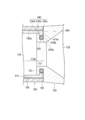
- FIG. 11 is a cross-sectional view showing a holding unit and a rotation mechanism according to Modification 2. It is a figure which shows the puncture needle assembly which concerns on 2nd Embodiment, Comprising: It is a perspective view which shows the state in which the medical elongate body and the puncture needle were connected. It is sectional drawing which expands and shows a part of catheter main body of the medical elongate body which concerns on 2nd Embodiment.
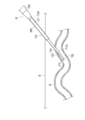
- FIGS. 6 to 9 are diagrams for explaining a usage example of the puncture needle assembly 10.
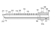
- 3 and 4 are cross-sectional views of the catheter body 110 along the longitudinal direction
- FIG. 5 is a cross-sectional view of the catheter hub 130 along the longitudinal direction.
- the puncture needle assembly 10 including the medical elongated body 100 and the puncture needle 200 will be described.
- the puncture needle assembly 10 is configured as an indwelling needle.
- the medical elongated body 100 is configured as an outer tube of an indwelling needle.
- the operator inserts the medical long body 100 and the puncture needle 200 with the medical long body 100 and the puncture needle 200 connected as shown in FIG. Puncture the blood vessel B of the patient.
- the surgeon punctures the blood vessel B of the patient with the medical elongated body 100 and the puncture needle 200, and then removes the puncture needle 200 from the medical elongated body 100 to perform medical treatment in the blood vessel B.
- a part of the catheter body 110 of the elongated body 100 is placed.
- the operator can insert various medical instruments such as a guide wire W into the blood vessel B via the lumen 115 of the catheter body 110.
- the medical elongated body 100 will be outlined with reference to FIGS. 1, 2, and 6.
- a catheter body 110 that is percutaneously inserted into a blood vessel B and a proximal end of the catheter body 110.
- a catheter hub 130 located on the side.
- the side of the medical elongated body 100 that is inserted into the living body (the lower side of FIGS. 3 and 4) is referred to as the “tip side”, and the side opposite to the distal side of the medical elongated body 100 is referred to. It shall be the "proximal side”.
- the direction in which the second region 113A of the catheter body 110 of the medical elongated body 100 extends (vertical direction in FIG. 4) is referred to as the “longitudinal direction (axial direction)”.
- the tip portion means a certain range including the tip (the most distal end) and the periphery thereof
- the base end portion means a certain range including the base end and the periphery thereof.
- the catheter body 110 has a distal end portion 111, a proximal end portion 113, and an inner cavity 115 extending between the distal end portion 111 and the proximal end portion 113.
- a tip opening portion 112 that communicates with the lumen 115 and opens to the outside of the catheter body 110 is formed.
- the tip portion 111 of the catheter body 110 has a tapered shape in which the outer diameter gradually decreases toward the tip side.
- the lumen 115 of the catheter body 110 has a substantially constant inner diameter d1 along the longitudinal direction.
- the catheter body 110 has a first region 111A and a second region 113A located on the proximal end side of the first region 111A and connected to the catheter hub 130.
- the first region 111A of the medical elongated body 100 is a fixed range in the longitudinal direction including the tip (the most distal end) of the catheter body 110. Further, the second region 113A of the medical elongated body 100 is a constant range in the longitudinal direction including the base end (the most proximal end) of the catheter body 110.
- the specific range of the first region 111A and the second region 113A is not particularly limited, but in the present embodiment, the first region 111A extends from the distal end of the catheter body 110 to the portion exposed from the protective sheath 180 in the catheter body 110. The range is.
- the second region 113A is a range covered by the protective sheath 180 of the catheter body 110 from the most proximal end of the catheter body 110. It should be noted that another region of the catheter body 110 may be formed between the first region 111A and the second region 113A.
- the first region 111A of the catheter body 110 has a bending portion 120 that bends with respect to the central axis C2 in the longitudinal direction of the second region 113A.
- the curved portion 120 is pre-shaped on the catheter body 110. Therefore, as shown in FIGS. 1 and 3, the catheter body 110 has a curved shape with the bending portion 120 as a base point in a state where the needle portion 210 of the puncture needle 200 is not inserted into the lumen 115 of the catheter body 110. Transforms into. In addition, as shown in FIGS. 2 and 4, when the needle portion 210 of the puncture needle 200 is inserted into the lumen 115 of the catheter body 110, the catheter body 110 becomes substantially linear along the shape of the needle portion 210. It transforms like an eggplant.
- the catheter body 110 passes through the central axis C1 of the distal end portion 111 of the first region 111A (the central position of the cross-section orthogonal to the axial direction of the distal end opening portion 112) in the first region 111A.
- the central axis is inclined with respect to the central axis C2 of the second region 113A.
- the curvature of the first area 111A when the first area 111A is curved is not particularly limited.
- the proximal end portion 113 located in the second region 113A of the catheter body 110 is connected to the catheter hub 130 so that the catheter body 110 can rotate relative to the catheter hub 130.
- the catheter hub 130 is arranged so as to cover the outer surface of the proximal end portion 113 of the catheter body 110.
- the vicinity of the distal end portion 131 of the catheter hub 130 is connected to the proximal end portion 113 of the catheter body 110.
- the catheter hub 130 has a lumen 135 formed inside the catheter hub 130.
- the lumen 135 of the catheter hub 130 communicates with the lumen 115 of the catheter body 110. Therefore, the operator can guide the guide wire W into the lumen 115 of the catheter body 110 by inserting the guide wire W into the lumen 135 of the catheter hub 130 and pushing the guide wire W toward the distal end side.
- the operator can project the guide wire W toward the distal end side from the catheter main body 110 through the distal end opening 112 of the catheter main body 110, as shown in FIG. 9. it can.
- the lumen 135 of the catheter hub 130 has a tapered shape in which the cross-sectional area gradually decreases toward the proximal end 113 side of the lumen 115 of the catheter body 110 in the cross section along the longitudinal direction shown in FIG. Therefore, the operator can easily move the guide wire W into the lumen 115 of the catheter body 110 by pushing the guide wire W inserted into the catheter hub 130 toward the distal end side by a manual operation.
- a proximal end portion 133 of the catheter hub 130 is provided with a proximal end opening portion 133 a for inserting the needle portion 210 of the puncture needle 200 and the guide wire W into the inner cavity 135 of the catheter hub 130. ing.
- the catheter hub 130 has a holding portion 140 in which a part of the second region 113A of the catheter body 110 is arranged.
- the holding portion 140 of the catheter hub 130 and a part of the second region 113A of the catheter body 110 allow relative rotation of the catheter body 110 with respect to the catheter hub 130.
- the rotation mechanism 150 that restricts the movement of the catheter body 110 in the longitudinal direction is configured by the contact between the holding portion 140 and the second region 113A of the catheter body 110.
- the holding portion 140 of the catheter hub 130 has a space portion 140 a in which the leakage suppression portion 160 is arranged between the convex portion 134 a formed at the tip of the catheter hub 130 and the outer surface of the catheter body 110. And a contact surface 134d that contacts a part of the catheter body 110.
- the second area 113A of the catheter body 110 has a convex portion 114a and a contact surface 114b that contacts the contact surface 134d of the holding portion 140.
- the contact surface 114b of the catheter body 110 is formed by the proximal end surface of the catheter body 110.
- the convex portion 134 a of the holding portion 140 projects toward the outer surface side of the catheter body 110.
- the contact surface 114b is a portion where the catheter body 110 and the catheter hub 130 at least contact each other when the operator pushes the catheter body 110 against the blood vessel of the patient.
- the convex portion 114a of the catheter body 110 and the convex portion 134a of the holding portion 140 are arranged so as to be hooked with each other while sandwiching the leakage suppressing portion 160 in the longitudinal direction of the catheter body 110.
- the catheter main body 110 is arranged in a state where the convex portion 114a of the catheter main body 110 and the convex portion 134a of the holding portion 140 are hooked as described above, so that the relative movement in the longitudinal direction with respect to the catheter hub 130 is restricted.
- the rotation mechanism 150 includes a leakage suppression unit 160 that suppresses blood from leaking from between the catheter body 110 and the catheter hub 130 (between the outer surface of the catheter body 110 and the catheter hub 130).
- the leakage suppression unit 160 is arranged in the space 140a formed between the outer surface of the catheter body 110 and the catheter hub 130 by the recess 134b of the holding unit 140.
- the leakage suppression unit 160 can be configured by a known O-ring, for example. However, the specific structure, material, cross-sectional shape, etc. of the leakage suppression unit 160 are not particularly limited.
- a coating material having lubricity for reducing friction generated between the leakage suppression unit 160 and the catheter body 110 and the catheter hub 130 can be provided on the outer surface of the leakage suppression unit 160. Further, when the leakage suppression unit 160 is composed of a resin O-ring or the like, it is preferable to use the leakage suppression unit 160 composed of a material having a surface property with high lubricity.
- the rotating mechanism 150 includes a friction reducing portion 170 that reduces friction generated between the catheter body 110 and the catheter hub 130 when the catheter body 110 rotates relative to the catheter hub 130.
- the friction reducing portion 170 is arranged on a part of the outer surface of the second region 113A of the catheter body 110 facing the space portion 140a in which the leakage suppressing portion 160 is arranged.
- the friction reducing portion 170 is made of a coating material having lubricity and coated on the outer surface of the catheter body 110.
- a coating material having lubricity for example, a known coating material such as silicone coating can be used.
- the specific material and thickness of the coating material are not particularly limited.
- the friction reducing section 170 may be provided at any part of the rotation mechanism 150, and the specific location of the friction reducing section 170 is not limited. As described above, the rotating mechanism 150 includes a part of the second region 113A of the catheter body 110 and the holding portion 140 of the catheter hub 130. Therefore, the friction reducing portion 170 may be arranged on a part of the catheter hub 130 (for example, the surface of the recess 134b).
- the friction reducing portion 170 is not limited to a specific configuration as long as it can reduce the friction generated between the catheter body 110 and the catheter hub 130.
- the friction reducing portion 170 may be configured by, for example, a minute uneven portion (textured portion) provided on the surface of the second region 113A of the catheter body 110 or the surface of the catheter hub 130. By providing such an uneven portion, the contact area between the second region 113A of the catheter body 110 and the catheter hub 130 can be reduced. Thereby, the friction generated between the catheter body 110 and the catheter hub 130 can be reduced.
- the second region 113A of the catheter body 110 has a marker portion 117 that indicates the bending direction of the first region 111A of the catheter body 110.
- the marker portion 117 is arranged on a part of the outer peripheral surface of the second region 113A as shown in FIGS.
- the marker portion 117 is arranged on the outer peripheral surface of the second area 113A at a position corresponding to the direction in which the first area 111A is curved (rightward in FIG. 3). That is, the marker portion 117 is arranged at a position that axially overlaps the bending direction of the first region 111A.
- the marker portion 117 is arranged in a portion exposed from the catheter hub 130 in the second region 113A so that the operator can visually confirm it.
- the operator protects the marker portion 117 in the entire length of the protective sheath 180 or in the portion overlapping with the marker portion 117 of the protective sheath 180. In order to be visible from the outside of 180, it is preferably transparent or translucent.
- the marker section 117 can be composed of, for example, a line, a figure, a symbol, a character or the like that is colored differently from the second area 113A. Further, the specific method of forming the marker portion 117 in the second region 113A, the specific position where the marker portion 117 is provided on the outer peripheral surface of the second region 113A, and the like are not particularly limited.
- the first region 111A has a slit 119 that defines the bending direction of the catheter body 110.
- a plurality of slits 119 are formed in the catheter body 110 at intervals in the longitudinal direction of the catheter body 110.
- Each slit 119 is formed in a part of the catheter body 110 in the circumferential direction.
- Each slit 119 is formed with a depth reaching the inner lumen 115 from the outer surface of the catheter body 110.
- the number, shape, position, etc. of the slits 119 are not particularly limited as long as it is possible to define the bending direction of the first region 111A of the catheter body 110.
- the slits 119 are formed in the first region 111A, so that the slits 119 are not formed in the circumferential direction of the first region 111A (opposite the slits 119 on an axially orthogonal sectional view). Side, and bends to the right in FIG. 3).
- the above-described marker portion 117 is arranged on the side where the slits 119 are not formed in the circumferential direction of the first region 111A (the side facing the slits 119 on the cross-sectional view orthogonal to the axis).
- the bending direction of the first region 111A of the catheter body 110 may be defined by a structure other than the slit 119.
- the bending direction of the first region 111A can be regulated by adjusting the thickness or the material of the material forming the first region 111A of the catheter body 110.
- the curved portion 120 of the catheter body 110 is thin and thick in a part in the circumferential direction, so that the curved portion 120 is easily curved to the side where the wall thickness is thin.
- the constituent material of the bending portion 120 of the catheter body 110 is formed to be flexible and hard in a part in the circumferential direction, the bending portion 120 is easily bent to the side formed of the flexible material. Become.
- the catheter body 110 may have a multilayer structure in which a plurality of layers made of resin are laminated. Further, in the catheter body 110, in order to prevent the catheter body 110 from kinking at the curved portion 120, a coil or a blade may be embedded in the tube wall of the catheter body 110. Further, in the catheter body 110, a bellows structure may be provided in a part of the first region 111A so that the first region 111A can be more smoothly curved with the bending portion 120 as a base point.
- a reinforcement body (wire or the like) is provided with a bellows structure to prevent the first region 111A of the catheter body 110 from expanding and contracting in the longitudinal direction. It is preferable to arrange them together.
- the medical elongated body 100 includes a protective sheath 180 that covers at least a part of the outer peripheral surface of the catheter body 110.
- the protective sheath 180 is a tubular member including a distal end portion 181, a proximal end portion 183, and an inner cavity 185 extending between the distal end portion 181 and the proximal end portion 183. I am configuring.
- a distal end opening 182 is formed at the distal end of the protective sheath 180 so as to project the catheter body 110 toward the distal end side of the protective sheath 180.
- the proximal end 183 of the protective sheath 180 is fixed to the distal end 131 of the catheter hub 130.
- the protective sheath 180 is not fixed to the catheter body 110. Therefore, the protective sheath 180 does not rotate in conjunction with the rotation of the catheter body 110 when the catheter body 110 rotates relative to the catheter hub 130.
- a gap 180a is preferably provided between the inner surface of the protective sheath 180 and the outer surface of the catheter body 110, as shown in FIG.
- the medical elongated body 100 can more reliably prevent the protective sheath 180 from rotating in conjunction with the rotation of the catheter body 110.
- the proximal end 183 of the protective sheath 180 can be fixed to the distal end 131 of the catheter hub 130 by, for example, adhesion or fusion.
- the length of the protective sheath 180 in the longitudinal direction, the wall thickness, the specific position for fixing the protective sheath 180 and the catheter hub 130, and the like are not particularly limited.
- the material forming the catheter body 110 is not particularly limited, but examples thereof include polyolefin such as polyethylene, polypropylene, ethylene-propylene copolymer, ethylene-vinyl acetate copolymer, thermoplastic resin such as soft polyvinyl chloride, polyurethane elastomer, Various elastomers such as polyamide elastomer and polyester elastomer, polyamide and the like can be used.
- polyolefin such as polyethylene, polypropylene, ethylene-propylene copolymer, ethylene-vinyl acetate copolymer, thermoplastic resin such as soft polyvinyl chloride, polyurethane elastomer, Various elastomers such as polyamide elastomer and polyester elastomer, polyamide and the like can be used.
- the catheter body 110 is formed more flexibly than the needle portion 210 of the puncture needle 200. Therefore, when the needle portion 210 of the puncture needle 200 is placed in the lumen 115 of the catheter body 110, the catheter body 110 can be deformed into a substantially linear shape by the needle portion 210.
- the material forming the protective sheath 180 is not particularly limited, but for example, the same materials as the above-mentioned materials exemplified as the material of the catheter body 110 can be used.
- the material forming the catheter hub 130 is not particularly limited, but for example, hard resin or metal can be used.
- the puncture needle 200 includes a needle portion 210 having a needle tip 211 capable of puncturing a patient's skin S and a blood vessel B, and a hub portion 220 arranged on the proximal end side of the needle portion 210.
- the needle portion 210 of the puncture needle 200 extends in a substantially straight line along the longitudinal direction of the needle portion 210. Inside the needle portion 210, a lumen 215 through which blood can flow is formed.
- the needle tip 211 is formed with a distal end opening 212 that communicates the inner cavity 215 of the needle 210 with the outside.
- An inner cavity (not shown) communicating with the inner cavity 215 of the needle section 210 is formed in the hub section 220.
- the operator confirms that blood (reverse blood) has flowed into the hub portion 220 to confirm that the needle tip 211 of the needle portion 210 has reached the blood vessel B. You can check.
- the hub portion 220 is preferably formed transparent so that blood flowing into the hub portion 220 can be viewed through the needle portion 210.
- FIG. 4 shows a state in which the needle portion 210 of the puncture needle 200 is arranged in the inner cavity 115 of the catheter body 110 of the medical elongated body 100.
- the first region 111A of the catheter body 110 is the second region 113A of the catheter body 110.
- the curved portion 120 is deformed so as to be parallel to the central axis C2 in the longitudinal direction. That is, when the needle portion 210 of the puncture needle 200 is arranged in the lumen 115 of the medical elongated body 100, the medical elongated body 100 has the central axis C1 of the first region 111A of the catheter body 110 and the catheter body.
- the central axis C2 of the second region 113A of 110 becomes substantially parallel, and the entire catheter body 110 including the first region 111A and the second region 113A is deformed so as to be substantially linear.
- the surgeon arranges the needle portion 210 of the puncture needle 200 in the inner cavity 115 of the catheter body 110 of the medical elongated body 100 so that the needle tip 211 of the needle portion 210 has a predetermined length.
- Only the catheter body 110 can be protruded toward the distal end side.
- the operator projects the needle tip 211 of the needle portion 210 of the puncture needle 200 from the inner lumen 115 of the catheter body 110 to the distal end side to connect the medical elongated body 100 and the puncture needle 200 to the needle.
- the needle tip 211 of the portion 210 can puncture the skin S and the blood vessel B of the patient.
- the outer diameter d2 of the needle portion 210 can be formed to have substantially the same size as the inner diameter (diameter of the lumen 115) d1 of the catheter body 110 or a smaller dimension than the inner diameter d1 of the medical elongated body 100.
- the outer diameter d2 of the needle portion 210 is at the distal end side of the catheter body 110.
- the size may be larger than the inner diameter d1 of the catheter body 110 in a range in which the needle portion 210 can be inserted into the lumen 115 of the catheter body 110.
- the material forming the needle portion 210 of the puncture needle 200 is not particularly limited, but, for example, a known metal can be used. Further, the material forming the hub portion 220 is not particularly limited, but for example, hard resin or metal can be used.
- the puncture needle assembly 10 is moved from the anatomical snuff box located on the instep Hb side of the hand H (for example, the left hand) or the position around the snuff box to the palmar artery (including the distal radial artery). ) B is accessed, and an example used for the procedure of dTRA (distal radial approach) for performing treatment through the vascular access site will be described.
- the operator Before puncturing the skin S and the blood vessel B of the patient's hand H with the puncture needle 200, the operator inserts the needle portion 210 of the puncture needle 200 into the medical elongated body 100 as shown in FIGS. 2 and 4.
- the puncture needle assembly 10 in which the medical elongated body 100 and the puncture needle 200 are connected to each other is provided in the lumen 115 of the catheter body 110.
- the operator inserts the needle tip 211 of the needle portion 210 of the puncture needle 200 into the skin S of the patient's hand H as shown in FIGS. 6 and 7. Puncture blood vessel B.
- the needle tip 211 of the needle portion 210 of the puncture needle 200 penetrates the blood vessel wall of the blood vessel B and reaches the inside of the blood vessel B, blood flowing through the blood vessel B via the inner cavity 215 (see FIG. 4) of the needle portion 210. Flows into the inner cavity of the hub portion 220 of the puncture needle 200.
- the operator can confirm that the needle tip 211 of the needle portion 210 of the puncture needle 200 has penetrated the blood vessel B by confirming the inflow of blood into the lumen of the hub portion 220.
- the operator inserts the needle tip 211 of the needle portion 210 of the puncture needle 200 into the skin of the hand H of the patient as shown in FIGS. 6 and 7 in a state in which the medical elongated body 100 and the puncture needle 200 are connected.
- the outer surface of the protective sheath 180 and the outer surface of the catheter body 110 are grasped by fingers and the like, and the catheter body 110 is pressed against the needle portion 210 of the puncture needle 200. Inadvertent rotation of the catheter body 110 relative to the catheter hub 130 may be prevented.
- the surgeon After reaching the inside of the blood vessel B with the needle tip 211 of the needle portion 210 of the puncture needle 200, the surgeon uses the puncture needle 200 from the lumen 115 of the catheter main body 110 of the medical elongated body 100 as shown in FIG. The needle portion 210 of is removed.
- the first area 111A of the catheter body 110 of the medical elongated body 100 has the curved portion 120 formed in the first area 111A. It is curved so as to follow the blood vessel B with the base point. The operator can easily confirm the bending direction of the bending portion 120 in the blood vessel B by checking the position of the marker portion 117 outside the living body of the patient.
- the operator holds the catheter hub 130 and the like of the medical elongated body 100 and pushes the catheter main body 110 into the blood vessel B by a manual operation, so that the blood vessel B The catheter body 110 is moved along.
- the blood vessel B selected as a puncture target by the dTRA procedure may meander at multiple points in the extending direction of the blood vessel B. Therefore, it may be difficult for the operator to move the catheter body 110 to a desired position in the blood vessel B only by pushing the catheter body 110 toward the blood vessel B by hand operation.
- the medical elongated body 100 When the catheter main body 110 is pushed toward the inside of the blood vessel B when the first region 111A of the catheter main body 110 contacts the inner wall of the blood vessel B, the medical elongated body 100 according to the present embodiment is removed from the inner wall of the blood vessel B.
- the force received causes the catheter body 110 to rotate relative to the catheter hub 130.
- the catheter body 110 rotates, the direction of the curved portion 120 of the catheter body 110 automatically changes, and the tip portion 111 of the catheter body 110 changes direction. Therefore, the operator can smoothly move the catheter main body 110 along the blood vessel B by pushing the catheter main body 110 toward the inside of the blood vessel B by a manual operation.
- the protective sheath 180 included in the medical elongated body 100 is fixed to the catheter hub 130 so as not to rotate in conjunction with the rotation of the catheter body 110, as described above. Therefore, even when the catheter body 110 is rotated in a state where the catheter body 110 is inserted into the blood vessel B to a position where the protective sheath 180 comes into contact with the patient's skin S, the operator works in conjunction with the rotation of the catheter body 110. It is possible to prevent the skin S of the patient from being twisted. Therefore, the operator can prevent the patient from feeling pain when the catheter body 110 rotates.
- the operator delivers the tip 111 of the catheter body 110 to a desired position in the blood vessel B, and then inserts the guide wire W into the blood vessel B via the catheter hub 130 and the catheter body 110.
- the guide wire W for example, a general wire (so-called mini guide wire) used when inserting a medical device such as an introducer into the blood vessel B can be used.
- the operator When inserting the guide wire W into the blood vessel B, the operator confirms the bending direction of the bending portion 120 based on the position of the marker portion 117, and then projects the guide wire W from the distal end opening 112 of the catheter body 110. Preferably. This is for the following reasons.
- the curved portion 120 is curved so that the distal end opening 112 of the catheter body 110 faces the direction close to the inner wall of the blood vessel B.
- the guide wire W projected from the distal end opening 112 may be abutted against the inner wall of the blood vessel B.
- the operator confirms the bending direction of the bending portion 120, confirms that the distal end opening portion 112 of the catheter body 110 is not arranged in the vicinity of the inner wall of the blood vessel B as shown in FIG.
- the medical elongated body 100 includes the catheter body 110 which is percutaneously inserted into the blood vessel B, and the catheter hub 130 which is located on the proximal end side of the catheter body 110.
- the main body 110 has an inner cavity 115, a first region 111A located on the distal end side, and a second region 113A located on the proximal end side of the first region 111A, and the first region 111A is the second region.
- 113A has a curved portion 120 that curves with respect to the central axis C2 in the longitudinal direction, and the second region 113A is connected to the catheter hub 130 so that the catheter body 110 can rotate relative to the catheter hub 130. ..
- the catheter body 110 when the first region 111A of the catheter body 110 comes into contact with the inner wall of the blood vessel B or the like, the force received from the inner wall of the blood vessel B causes the catheter body 110 to move. Rotate relative to. Thereby, the direction of the curved portion 120 of the catheter body 110 automatically changes, and the tip portion 111 of the catheter body 110 changes direction. Therefore, in the medical elongated body 100, even if the blood vessel B has many meandering portions, the catheter body 110 can easily follow the movement of the blood vessel.
- the medical elongated body 100 includes a protective sheath 180 that covers at least a part of the outer peripheral surface of the catheter body 110.
- the protective sheath 180 is fixed to the catheter hub 130 and does not rotate in conjunction with the rotation of the catheter body 110 when the catheter body 110 rotates relative to the catheter hub 130. Therefore, the operator can prevent the skin S of the patient from being twisted in conjunction with the rotation of the catheter body 110 when the catheter body 110 is rotated with the catheter body 110 inserted into the blood vessel B.
- the catheter hub 130 has a holding portion 140 in which a part of the second region 113A of the catheter body 110 is arranged.
- the holding portion 140 and the second region 113A of the catheter body 110 allow the relative rotation of the catheter body 110 with respect to the catheter hub 130, while the holding portion 140 and the second region 113A of the catheter body 110 contact each other to cause the catheter body 110 to move.
- a rotation mechanism 150 is formed that limits movement in the longitudinal direction.
- the rotation mechanism 150 also includes a leakage suppression unit 160 that suppresses blood from leaking between the catheter body 110 and the catheter hub 130.
- the medical elongated body 100 allows the catheter body 110 to rotate with respect to the catheter hub 130 by the rotation mechanism 150 configured by a part of the second region 113A of the catheter body 110 and the holding portion 140 of the catheter hub 130. It is possible to prevent the catheter body 110 from moving in the longitudinal direction. Further, in the medical elongated body 100, the leakage suppressing unit 160 included in the rotating mechanism 150 can preferably prevent blood from leaking between the catheter body 110 and the catheter hub 130.
- the rotating mechanism 150 has a friction reducing portion 170 that reduces friction generated between the catheter body 110 and the catheter hub 130 when the catheter body 110 rotates relative to the catheter hub 130. Therefore, in the medical elongated body 100, the catheter body 110 can smoothly rotate with respect to the catheter hub 130.
- the second region 113A of the catheter body 110 has a marker portion 117 indicating the bending direction of the first region 111A of the catheter body 110. Therefore, the operator can easily confirm the bending direction of the bending portion 120 in the blood vessel B by checking the position of the marker portion 117 outside the living body of the patient.
- the first region 111A of the catheter body 110 has a slit 119 that defines the bending direction of the catheter body 110. Therefore, in the catheter body 110, when the external force is not applied to the catheter body 110 (for example, the needle portion 210 of the puncture needle 200 is not inserted into the lumen 115 of the catheter body 110), the curved portion 120 has a predetermined shape. Bend more reliably in the direction of.
- the puncture needle assembly 10 includes the medical elongated body 100 and the puncture needle 200 that can be arranged in the lumen 115 of the catheter body 110 of the medical elongated body 100.
- the first region 111A of the catheter body 110 is aligned with the central axis C2 in the longitudinal direction of the second region 113A of the catheter body 110 with the puncture needle 200 arranged in the lumen 115 of the catheter body 110.
- the curved portion 120 is deformed so as to be parallel to each other.
- the catheter body of the medical long body 100 is used. It is possible to prevent the first region 111A of 110 from being curved. Further, the puncture needle assembly 10 punctures the blood vessel B of the patient with the puncture needle 200, and then withdraws the puncture needle 200 from the inner cavity 115 of the catheter body 110 of the medical elongated body 100, thereby removing the catheter body 110.
- the bending portion 120 can be bent in a predetermined direction.
- the medical elongated body 100 has a rotation suppressing mechanism that restricts relative rotation of the catheter body 110 with respect to the catheter hub 130 in a state where the puncture needle 200 is placed in the lumen 115 of the catheter body 110.
- the rotation suppressing mechanism can be configured by, for example, a part of the outer surface of the needle portion 210 and a part of the inner surface of the catheter body 110 that cause frictional resistance between the needle portion 210 and the catheter body 110.
- a part of the outer diameter d2 of the needle portion 210 is larger than the inner diameter d1 of the medical elongated body 100 in a range in which the needle portion 210 can be inserted into the inner cavity 115 of the medical elongated body 100. Can be formed with.
- a rotation suppressing member for example, made of resin
- the rotation suppressing member is attached to the outer peripheral surface of the needle portion 210 by fitting or the like so as to increase a part of the outer diameter d2 of the needle portion 210. Therefore, when the needle portion 210 is arranged in the inner cavity 115 of the catheter body 110, a frictional force can be generated between the outer surface of the rotation suppressing member and the inner surface of the catheter body 110.
- the rotation suppressing member may move integrally with the needle portion 210 as the needle portion 210 is inserted into the lumen 115 of the catheter body 110 and the needle portion 210 is removed from the lumen 115 of the catheter body 110. Further, it is preferable that the needle 210 is firmly fixed.
- the puncture needle assembly 10 is arranged between the inner surface of the catheter body 110 and the outer surface of the needle portion 210 in a state where the needle portion 210 of the puncture needle 200 is arranged in the lumen 115 of the catheter body 110.
- a frictional force is generated. Therefore, the operator can prevent the catheter body 110 from rotating carelessly with respect to the catheter hub 130 in a state where the medical elongated body 100 and the puncture needle 200 are connected. That is, in the medical elongated body 100, the relative rotation of the catheter body 110 with respect to the catheter hub 130 is limited in a state where the puncture needle 200 is placed in the lumen 115 of the catheter body 110.
- the puncture needle assembly 10 punctures the skin S and the blood vessel B of the patient with the puncture needle 200 in a state in which the medical elongated body 100 and the puncture needle 200 are connected, the catheter body 110 with respect to the catheter hub 130. It can be prevented from rotating carelessly.
- the specific structure of the holding unit and the rotation mechanism of the medical elongated body 100 is not limited as long as the rotation of the catheter body 110 relative to the catheter hub 130 and the movement of the catheter body 110 in the longitudinal direction can be restricted.
- an example of the holding unit and the rotating mechanism will be described.
- FIG. 10 shows a holding unit 340 and a rotation mechanism 350 according to the first modification.
- the tip portion 131 of the catheter hub 130 is arranged on the inner surface side of the second region 113A of the catheter body 110. Therefore, the tip portion 131 of the catheter hub 130 is covered with the second region 113A of the catheter body 110.
- the holding portion 340 of the catheter hub 130 includes a convex portion 334a formed at the tip of the catheter hub 130 and a concave portion 334b forming a space portion 340a in which the leakage suppressing portion 160 is arranged between the convex portion 334a and the inner surface of the catheter body 110. , A contact surface 334d that contacts a part of the catheter body 110.
- the second region 113A of the catheter body 110 has a protrusion 314a and a contact surface 314b that contacts the contact surface 334d of the holding portion 340.
- the convex portion 314 a of the catheter body 110 projects toward the inner lumen 135 side of the catheter hub 130.
- the convex portion 334 a of the holding portion 340 projects toward the inner surface side of the catheter body 110.
- the convex portion 314a of the catheter body 110 and the convex portion 334a of the holding portion 340 are arranged so as to be hooked to each other while sandwiching the leakage suppressing portion 160 in the longitudinal direction of the catheter body 110.
- the catheter main body 110 is arranged such that the convex portion 314a of the catheter main body 110 and the convex portion 334a of the holding portion 340 are hooked as described above, so that the relative movement in the longitudinal direction with respect to the catheter hub 130 is limited.
- FIG. 11 shows a holding unit 440 and a rotation mechanism 450 according to the second modification.
- the tip end portion 131 of the catheter hub 130 is arranged on the inner surface side of the second region 113A of the catheter body 110. Therefore, the tip portion 131 of the catheter hub 130 is covered with the second region 113A of the catheter body 110.
- the holding portion 440 of the catheter hub 130 includes a convex portion 434a formed at the distal end of the catheter hub 130 and a concave portion 434b forming a space portion 440a in which the leakage suppressing portion 160 is arranged between the convex portion 434a and the inner surface of the catheter body 110. , A contact surface 434c that contacts a part of the catheter body 110.
- the second region 113A of the catheter body 110 has a convex portion 414b inserted into the concave portion 434b of the holding portion 440 and a contact surface 414c that comes into contact with the contact surface 434c of the holding portion 440.
- the convex portion 414b of the catheter main body 110 projects toward the lumen 135 side of the catheter hub 130.
- the convex portion 434 a of the holding portion 440 projects toward the inner surface side of the catheter body 110.
- the convex portion 414b of the catheter body 110 and the convex portion 434a of the holding portion 440 are arranged so as to be hooked to each other while sandwiching the leakage suppression portion 160 in the longitudinal direction of the catheter body 110.
- the catheter main body 110 is arranged such that the convex portion 414b of the catheter main body 110 and the convex portion 434a of the holding portion 440 are hooked as described above, so that the relative movement in the longitudinal direction with respect to the catheter hub 130 is restricted.
- the medical elongated body 100 includes a predetermined limiting member 190.
- the puncture needle assembly 20 according to the second embodiment is different from the puncture needle assembly 10 according to the first embodiment.
- the limiting member 190 is attachable to the catheter body 110, and limits the relative rotation of the catheter body 110 with respect to the catheter hub 130 while being attached to the catheter body 110.
- the limiting member 190 has a pair of holding portions 191a and 191b that can apply a holding force to the outer peripheral surface of the catheter body 110, and an operation portion 193 that relatively moves the respective holding portions 191a and 191b toward and away from each other. ..
- the limiting member 190 is formed of a clip structure member capable of sandwiching the outer peripheral surface of the catheter body 110 between the sandwiching portions 191a and 191b. The operator can widen or narrow the distance between the sandwiching portion 191a and the sandwiching portion 191b by gripping the operation portion 193 and applying a force.
- the operator places the restriction member 190 on the outer surface of the protective sheath 180 or the outer surface of the catheter body 110 with the needle portion 210 of the puncture needle 200 arranged in the lumen 115 of the catheter body 110. Put it on.
- the holding portions 191a and 191b of the limiting member 190 hold the protective sheath 180 and the catheter body 110, and fix (hold) the catheter body 110 to the needle portion 210 of the puncture needle 200. Therefore, the operator can prevent the catheter body 110 from rotating carelessly with respect to the catheter hub 130 in a state in which the needle portion 210 of the puncture needle 200 is arranged in the lumen 115 of the catheter body 110.
- the operator uses his or her finger or the like to attach the puncture needle 200 to the outer surface of the protective sheath 180 or the outer surface of the catheter body 110. Since it is not necessary to press the needle portion 210 against the needle portion 210, the procedure using the puncture needle assembly 20 can be smoothly advanced.
- the operator When the operator removes the needle portion 210 of the puncture needle 200 from the lumen 115 of the catheter body 110, the operator can operate the operation portion 193 to release the restriction member 190 from holding the catheter body 110.
- the limiting member 190 is not limited to a specific configuration as long as it can limit the rotation of the catheter body 110.
- the restricting member 190 includes a screw hole that penetrates the catheter body 110 and a screw member that can be screwed into the screw hole and that can contact the outer surface of the needle portion 210 of the puncture needle 200 through the screw hole. Is also possible.
- the target of application of the medical elongated body is not limited to the outer tube of the puncture needle assembly (indwelling needle).
- the medical elongated body can be widely applied to medical devices intended to deliver various members, instruments, substances and the like into a blood vessel of a patient via the lumen of the medical elongated body. ..
- the use of the medical long body and the puncture needle assembly is not limited to the dTRA procedure described in the embodiment, but can be applied to other procedures.
- each member constituting the medical elongated body and the puncture needle assembly are not particularly limited as long as the effects of the present invention are exhibited. , And can be arbitrarily changed and replaced. Further, the medical elongated body and the puncture needle assembly can be appropriately added with arbitrary constituent members and the like which have not been particularly described in the specification, and additional members described in the specification. Can be omitted as appropriate.
Landscapes
- Health & Medical Sciences (AREA)
- Life Sciences & Earth Sciences (AREA)
- Heart & Thoracic Surgery (AREA)
- Biomedical Technology (AREA)
- Engineering & Computer Science (AREA)
- Anesthesiology (AREA)
- Pulmonology (AREA)
- Hematology (AREA)
- Animal Behavior & Ethology (AREA)
- General Health & Medical Sciences (AREA)
- Public Health (AREA)
- Veterinary Medicine (AREA)
- Biophysics (AREA)
- Media Introduction/Drainage Providing Device (AREA)
Abstract
【課題】蛇行した血管への追従性がより一層向上された医療用長尺体及び当該医療用長尺体を備える穿刺針組立体を提供することを目的とする。 【解決手段】医療用長尺体100は、経皮的に血管B内に挿入されるカテーテル本体110と、カテーテル本体の基端側に位置するカテーテルハブ130と、を備え、カテーテル本体は、内腔115と、先端側に位置する第1領域111Aと、第1領域の基端側に位置する第2領域113Aと、を有し、第1領域は、第2領域の長手方向の中心軸C2に対して湾曲する湾曲部120を有し、第2領域は、カテーテル本体がカテーテルハブに対して相対的に回転できるようにカテーテルハブに接続される。
Description
本発明は、医療用長尺体及び穿刺針組立体に関する。
患者の血管内へ治療デバイスを挿入する際や血管へのアクセス経路を形成する際、内腔が形成されたカテーテル本体を備える医療用長尺体が使用される。医療用長尺体の一つとして、例えば、穿刺針とともに使用される外筒管が知られている(特許文献1を参照)。
術者は、穿刺針と外筒管を接続した状態で、穿刺針を患者の皮膚及び血管に穿刺する。なお、穿刺針と外筒管を接続した状態とは、穿刺針の針部を外筒管のカテーテル本体の内腔に挿入し、カテーテル本体の先端開口部から穿刺針の針部の針先を突出させた状態である。術者は、穿刺針とともに外筒管を患者の皮膚及び血管に穿刺し、穿刺針の針部の針先が血管に到達した後、穿刺針の針部を外筒管のカテーテル本体の内腔から抜去する。術者は、外筒管のカテーテル本体の内腔から穿刺針の針部を抜去した後、外筒管が血管に留置された状態で、カテーテル本体の内腔にガイドワイヤを挿入することにより、カテーテル本体の内腔を介してガイドワイヤを生体内の所望の位置まで送達することができる。
例えば、蛇行した血管内に外筒管のカテーテル本体を挿入する場合、術者は、穿刺針とともに外筒管のカテーテル本体を血管に沿わせて円滑に移動させることが難しくなる。そのため、外筒管は、血管に対するカテーテル本体の追従性が低下する。
特許文献1に記載された外筒管のカテーテル本体は、湾曲形状をなすように予め癖付けがなされている。そのため、カテーテル本体は、穿刺針がカテーテル本体の内腔に挿入された状態では、穿刺針の形状に沿って略直線状に延びる。また、カテーテル本体は、カテーテル本体の内腔から穿刺針が抜去されると、癖付けされた湾曲形状に変形する。したがって、術者は、特許文献1に記載された外筒管のカテーテル本体の先端を血管の蛇行部付近に配置した後、カテーテル本体の内腔から穿刺針を抜去することにより、カテーテル本体を血管に追従させるように湾曲させることができる。そのため、術者は、カテーテル本体の内腔を介して蛇行した血管内に沿ってガイドワイヤを送達することができる。
しかしながら、血管が、当該血管の延在方向の複数の箇所で蛇行している場合、特許文献1に記載された外筒管を使用した場合であったとしても、外筒管のカテーテル本体が血管の各蛇行箇所に追従して変形することは困難である。
本発明は上記課題を鑑みてなされたものであり、蛇行した血管への追従性がより一層向上された医療用長尺体及び当該医療用長尺体を備える穿刺針組立体を提供することを目的とする。
本発明に係る医療用長尺体は、経皮的に血管内に挿入されるカテーテル本体と、前記カテーテル本体の基端側に位置するカテーテルハブと、を備え、前記カテーテル本体は、内腔と、先端側に位置する第1領域と、前記第1領域の基端側に位置する第2領域と、を有し、前記第1領域は、前記第2領域の長手方向の中心軸に対して湾曲する湾曲部を有し、前記第2領域は、前記カテーテル本体が前記カテーテルハブに対して相対的に回転できるように前記カテーテルハブに接続される。
本発明に係る医療用長尺体によれば、カテーテル本体の第1領域の湾曲部が血管の内壁等に接触した際、血管の内壁から受ける力により、カテーテル本体がカテーテルハブに対して相対的に回転する。それにより、カテーテル本体の湾曲部の方向が自動的に変化し、カテーテル本体の先端部が方向転換する。したがって、上記の医療用長尺体は、蛇行箇所が多い血管であっても、カテーテル本体が血管走行に沿って追従し易くなる。
以下、添付した図面を参照しながら、本発明の実施形態を説明する。なお、以下の記載は特許請求の範囲に記載される技術的範囲や用語の意義を限定するものではない。また、図面の寸法比率は説明の都合上誇張されており、実際の比率とは異なる場合がある。
(第1実施形態)
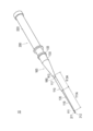
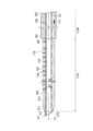
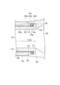
図1~図5は、第1実施形態に係る穿刺針組立体10を説明するための図、図6~図9は、穿刺針組立体10の使用例を説明するための図である。なお、図3、図4は、長手方向に沿うカテーテル本体110の断面図であり、図5は、長手方向に沿うカテーテルハブ130の断面図である。
図1~図5は、第1実施形態に係る穿刺針組立体10を説明するための図、図6~図9は、穿刺針組立体10の使用例を説明するための図である。なお、図3、図4は、長手方向に沿うカテーテル本体110の断面図であり、図5は、長手方向に沿うカテーテルハブ130の断面図である。
本実施形態の説明では、医療用長尺体100及び穿刺針200を備える穿刺針組立体10を説明する。穿刺針組立体10は留置針として構成している。医療用長尺体100は留置針の外筒管として構成している。
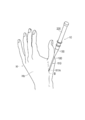
術者は、穿刺針組立体10を使用した手技において、図2に示すように、医療用長尺体100及び穿刺針200が接続された状態で、医療用長尺体100及び穿刺針200を患者の血管Bに穿刺する。術者は、図6に示すように、医療用長尺体100及び穿刺針200を患者の血管Bに穿刺した後、穿刺針200を医療用長尺体100から抜去し、血管B内に医療用長尺体100のカテーテル本体110の一部を留置する。術者は、図9に示すように、カテーテル本体110の内腔115を介して血管B内にガイドワイヤW等の各種の医療器具を挿入することができる。
<医療用長尺体>
本実施形態に係る医療用長尺体100は、図1、図2、図6を参照して概説すると、経皮的に血管B内に挿入されるカテーテル本体110と、カテーテル本体110の基端側に位置するカテーテルハブ130と、を備えている。
本実施形態に係る医療用長尺体100は、図1、図2、図6を参照して概説すると、経皮的に血管B内に挿入されるカテーテル本体110と、カテーテル本体110の基端側に位置するカテーテルハブ130と、を備えている。
本明細書では、医療用長尺体100の生体内に挿入される側(図3及び図4の下側)を「先端側」とし、医療用長尺体100の先端側とは反対側を「基端側」とする。また、医療用長尺体100のカテーテル本体110の第2領域113Aが延伸する方向(図4の上下方向)を「長手方向(軸方向)」とする。また、実施形態の説明において、先端部とは、先端(最先端)及びその周辺を含む一定の範囲を意味し、基端部とは、基端及びその周辺を含む一定の範囲を意味する。
カテーテル本体110は、先端部111と、基端部113と、先端部111と基端部113との間に延びる内腔115と、を有している。
カテーテル本体110の先端には、内腔115と連通する共に、カテーテル本体110の外部へ開口する先端開口部112が形成されている。カテーテル本体110の先端部111は、図3に示すように、先端側に向けて外径が漸減するテーパー形状を有している。カテーテル本体110の内腔115は、長手方向に沿って略一定の内径d1を有する。
カテーテル本体110は、第1領域111Aと、第1領域111Aの基端側に位置し、カテーテルハブ130と接続した第2領域113Aと、を有している。
医療用長尺体100の第1領域111Aは、カテーテル本体110の先端(最先端)を含む長手方向の一定の範囲である。また、医療用長尺体100の第2領域113Aは、カテーテル本体110の基端(最基端)を含む長手方向の一定の範囲である。第1領域111A及び第2領域113Aの具体的な範囲は特に限定されないが、本実施形態では、第1領域111Aは、カテーテル本体110の最先端からカテーテル本体110において保護シース180から露出した部分までの範囲とする。また、第2領域113Aは、カテーテル本体110の最基端からカテーテル本体110の保護シース180により覆われた範囲とする。なお、第1領域111Aと第2領域113Aの間には、カテーテル本体110の他の領域が形成されていてもよい。
カテーテル本体110の第1領域111Aは、図1、図3に示すように、第2領域113Aの長手方向の中心軸C2に対して湾曲する湾曲部120を有している。
湾曲部120は、カテーテル本体110に予め形状付けされている。そのため、図1、図3に示すように、カテーテル本体110は、カテーテル本体110の内腔115に穿刺針200の針部210が挿入されていない状態では、湾曲部120を基点にして湾曲した形状に変形する。また、カテーテル本体110は、図2、図4に示すように、カテーテル本体110の内腔115に穿刺針200の針部210が挿入されると、針部210の形状に沿って略直線状をなすように変形する。
図3に示すように、第2領域113Aには、湾曲部120が形成されていない。そのため、カテーテル本体110は、図3に示すように、第1領域111Aが湾曲した状態において、第1領域111Aの先端部111の中心軸C1(先端開口部112の軸直交断面の中心位置を通る中心軸)が第2領域113Aの中心軸C2に対して傾斜する。なお、第1領域111Aが湾曲した際の第1領域111Aの曲率は特に限定されない。
図5に示すように、カテーテル本体110の第2領域113Aに位置する基端部113は、カテーテル本体110がカテーテルハブ130に対して相対的に回転できるようにカテーテルハブ130に接続されている。カテーテルハブ130は、カテーテル本体110の基端部113の外表面を覆うように配置されている。
図5に示すように、カテーテルハブ130は、カテーテルハブ130の先端部131付近がカテーテル本体110の基端部113と接続されている。カテーテルハブ130は、カテーテルハブ130の内部に形成された内腔135を有している。カテーテルハブ130の内腔135は、カテーテル本体110の内腔115と連通している。したがって、術者は、カテーテルハブ130の内腔135にガイドワイヤWを挿入し、ガイドワイヤWを先端側へ押し込むことにより、カテーテル本体110の内腔115にガイドワイヤWを案内することができる。術者は、ガイドワイヤWをさらに先端側へ押し込むことにより、図9に示すように、カテーテル本体110の先端開口部112を介してカテーテル本体110よりも先端側へガイドワイヤWを突出させることができる。
カテーテルハブ130の内腔135は、図5に示す長手方向に沿う断面において、カテーテル本体110の内腔115の基端部113側に向けて断面積が漸減するテーパー形状を有している。そのため、術者は、カテーテルハブ130内に挿入したガイドワイヤWを手元の操作で先端側に向けて押し込むことにより、ガイドワイヤWをカテーテル本体110の内腔115へ容易に移動させることができる。
図1に示すように、カテーテルハブ130の基端部133には、カテーテルハブ130の内腔135へ穿刺針200の針部210やガイドワイヤWを挿入するための基端開口部133aが設けられている。
図5に示すように、カテーテルハブ130は、カテーテル本体110の第2領域113Aの一部が配置される保持部140を有している。
本実施形態に係る医療用長尺体100では、カテーテルハブ130の保持部140とカテーテル本体110の第2領域113Aの一部は、カテーテル本体110のカテーテルハブ130に対する相対的な回転を許容しつつ、保持部140とカテーテル本体110の第2領域113Aの接触によりカテーテル本体110の長手方向の移動を制限する回転機構150を構成する。
図5に示すように、カテーテルハブ130の保持部140は、カテーテルハブ130の先端に形成された凸部134aと、カテーテル本体110の外表面との間に漏洩抑制部160を配置する空間部140aを形成する凹部134bと、カテーテル本体110の一部と接触する接触面134dと、を有している。
カテーテル本体110の第2領域113Aは、凸部114aと、保持部140の接触面134dに接触する接触面114bと、を有している。カテーテル本体110の接触面114bは、カテーテル本体110の基端面で形成している。保持部140の凸部134aは、カテーテル本体110の外表面側に向けて突出している。なお、接触面114bは、術者が患者の血管に対してカテーテル本体110を押し進める際、カテーテル本体110とカテーテルハブ130とが少なくとも接触する部分である。カテーテル本体110は、カテーテルハブ130に対して相対的に回転する際、カテーテル本体110が摩擦低減部170と接触することでカテーテル本体110の回転が安定する。
カテーテル本体110の凸部114aと保持部140の凸部134aは、漏洩抑制部160をカテーテル本体110の長手方向において挟み込んだ状態で互いに引っ掛けて配置されている。カテーテル本体110は、カテーテル本体110の凸部114aと保持部140の凸部134aとが上記のように引っ掛かった状態で配置されることにより、カテーテルハブ130に対する長手方向の相対的な移動が制限される。
回転機構150は、カテーテル本体110とカテーテルハブ130との間(カテーテル本体110の外表面とカテーテルハブ130との間)から血液が漏洩することを抑制する漏洩抑制部160を備えている。
漏洩抑制部160は、保持部140の凹部134bにより、カテーテル本体110の外表面とカテーテルハブ130との間に形成された空間部140aに配置されている。
漏洩抑制部160は、例えば、公知のOリングで構成することができる。ただし、漏洩抑制部160の具体的な構造、材質、断面形状等は特に限定されない。
漏洩抑制部160の外表面には、漏洩抑制部160とカテーテル本体110及びカテーテルハブ130との間で生じる摩擦を低減するための潤滑性を備えるコーティング材を設けることができる。また、漏洩抑制部160が樹脂製のOリング等で構成される場合、漏洩抑制部160には潤滑性の高い表面性状を備える材質で構成されたものを用いることが好ましい。
回転機構150は、図5に示すように、カテーテル本体110がカテーテルハブ130に対して相対的に回転する際にカテーテル本体110とカテーテルハブ130との間に生じる摩擦を低減する摩擦低減部170を有している。
摩擦低減部170は、カテーテル本体110の第2領域113Aの外表面において漏洩抑制部160が配置された空間部140aに臨む一部に配置している。
摩擦低減部170は、カテーテル本体110の外表面にコーティングされた潤滑性を備えるコーティング材で構成している。潤滑性を備えるコーティング材としては、例えば、シリコーンコーティング等の公知のコーティング材を用いることができる。コーティング材の具体的な材質や厚み等は、特に限定されない。
摩擦低減部170は、回転機構150のいずれかの部位に設けられていればよく、摩擦低減部170の配置箇所の具体的な位置は限定されない。前述したように、回転機構150は、カテーテル本体110の第2領域113Aの一部とカテーテルハブ130の保持部140により構成されている。そのため、摩擦低減部170は、カテーテルハブ130の一部(例えば、凹部134bの表面)に配置してもよい。
また、摩擦低減部170は、カテーテル本体110とカテーテルハブ130の間に生じる摩擦を低減することが可能な限り、具体的な構成は限定されない。摩擦低減部170は、例えば、カテーテル本体110の第2領域113Aの表面やカテーテルハブ130の表面に設けられる微小な凹凸部(しぼ加工部)で構成してもよい。このような凹凸部を設けることにより、カテーテル本体110の第2領域113Aとカテーテルハブ130の接触面積を低減させることができる。それにより、カテーテル本体110とカテーテルハブ130の間に生じる摩擦を低減させることができる。
図1、図3、図9に示すように、カテーテル本体110の第2領域113Aは、カテーテル本体110の第1領域111Aの湾曲方向を示すマーカー部117を有している。
マーカー部117は、図1、図3に示すように、第2領域113Aの外周面の一部に配置している。マーカー部117は、第2領域113Aの外周面において、第1領域111Aが湾曲する方向(図3の右方向)に対応した位置に配置している。すなわち、マーカー部117は、第1領域111Aが湾曲する方向と軸方向に重なる位置に配置されている。
マーカー部117は、術者が目視により確認することが可能となるように、第2領域113Aにおいてカテーテルハブ130から露出した部分に配置している。なお、医療用長尺体100に後述する保護シース180が備えられる場合、保護シース180の長手方向に亘る全体又は保護シース180のマーカー部117と重なる部分は、術者がマーカー部117を保護シース180の外部から視認できるようにするために、透明や半透明であることが好ましい。
マーカー部117は、例えば、第2領域113Aと異なる色が付された線、図形、記号、文字等で構成することができる。また、マーカー部117を第2領域113Aに形成する具体的な方法や、第2領域113Aの外周面上においてマーカー部117が設けられる具体的な位置等は特に限定されない。
図1、図3に示すように、第1領域111Aは、カテーテル本体110の湾曲方向を規定するスリット119を有している。
カテーテル本体110には、カテーテル本体110の長手方向に間隔を空けて複数のスリット119が形成されている。各スリット119は、カテーテル本体110の周方向の一部に形成されている。各スリット119は、カテーテル本体110の外表面から内腔115に達する深さで形成している。なお、スリット119の個数、形状、位置等は、カテーテル本体110の第1領域111Aの湾曲方向を規定することが可能な限り、特に限定されない。
カテーテル本体110は、各スリット119が第1領域111Aに形成されることにより、第1領域111Aの周方向において各スリット119が形成されていない側(軸直交断面図上において各スリット119と対向する側であり、図3の右側)に湾曲する。前述したマーカー部117は、第1領域111Aの周方向において各スリット119が形成されていない側(軸直交断面図上において各スリット119と対向する側)に配置している。
カテーテル本体110の第1領域111Aの湾曲方向は、スリット119以外の構造で規定してもよい。例えば、カテーテル本体110の第1領域111Aを形成する材料の厚みや材質等を調整して第1領域111Aの湾曲方向を規定することができる。カテーテル本体110は、カテーテル本体110の湾曲部120の肉厚が周方向の一部で薄く及び厚く形成されることにより、湾曲部120が肉厚の薄い側に湾曲し易くなる。また、カテーテル本体110は、カテーテル本体110の湾曲部120の構成材料が周方向の一部で柔軟及び硬質に形成されることにより、湾曲部120が柔軟な材料で形成された側に湾曲し易くなる。
また、カテーテル本体110は、樹脂からなる複数の層が積層された多層構造で構成されていてもよい。また、カテーテル本体110は、カテーテル本体110が湾曲部120でキンクすることを防止するために、カテーテル本体110の管壁内にコイルやブレードを埋設されていてもよい。また、カテーテル本体110は、湾曲部120を基点にして第1領域111Aがより円滑に湾曲するようにするために、第1領域111Aの一部に蛇腹構造が備えられていてもよい。なお、カテーテル本体110の第1領域111Aの一部に蛇腹構造が備えられる場合、カテーテル本体110の第1領域111Aが長手方向に伸縮することを防止するために補強体(線材等)を蛇腹構造とともに配置することが好ましい。
図1、図3、図5に示すように、医療用長尺体100は、カテーテル本体110の外周面の少なくとも一部を覆う保護シース180を備えている。
保護シース180は、図3、図5に示すように、先端部181と、基端部183と、先端部181と基端部183との間に延びる内腔185と、を備える管状の部材で構成している。
保護シース180の先端には、図3、図4に示すように、カテーテル本体110を保護シース180の先端側に突出させる先端開口部182が形成されている。
保護シース180の基端部183は、カテーテルハブ130の先端部131に固定されている。保護シース180は、カテーテル本体110とは固定されていない。そのため、保護シース180は、カテーテル本体110がカテーテルハブ130に対して相対的に回転する際、カテーテル本体110の回転に連動して回転しない。
保護シース180の内表面とカテーテル本体110の外表面との間には、図5に示すように、隙間180aを設けることが好ましい。医療用長尺体100は、隙間180aが設けられることにより、カテーテル本体110が回転した際に保護シース180が連動して回転することをより確実に防止することができる。
保護シース180の基端部183は、例えば、接着や融着によりカテーテルハブ130の先端部131に対して固定することができる。なお、保護シース180の長手方向の長さ、肉厚、保護シース180とカテーテルハブ130とを固定する具体的な位置等は特に限定されない。
カテーテル本体110を形成する材料は特に限定されないが、例えば、ポリエチレン、ポリプロピレン、エチレン-プロピレン共重合体、エチレン-酢酸ビニル共重合体等のポリオレフィン、軟質ポリ塩化ビニル等の熱可塑性樹脂、ポリウレタンエラストマー、ポリアミドエラストマー、ポリエステルエラストマー等の各種エラストマー、ポリアミド等を用いることができる。
本実施形態では、カテーテル本体110は、穿刺針200の針部210よりも柔軟に形成している。そのため、カテーテル本体110の内腔115に穿刺針200の針部210を配置した際、カテーテル本体110を針部210によって略直線状に変形させることができる。
保護シース180を形成する材料も特に限定されないが、例えば、カテーテル本体110の材料として例示した上記の各材料と同様のものを用いることができる。
カテーテルハブ130を形成する材料は特に限定されないが、例えば、硬質の樹脂や金属等を用いることができる。
<穿刺針>
図1に示すように、穿刺針200は、患者の皮膚S及び血管Bを穿刺可能な針先211を備える針部210と、針部210の基端側に配置されたハブ部220と、を有している。
図1に示すように、穿刺針200は、患者の皮膚S及び血管Bを穿刺可能な針先211を備える針部210と、針部210の基端側に配置されたハブ部220と、を有している。
穿刺針200の針部210は、針部210の長手方向に沿って略直線状に延在している。針部210の内部には、血液が流通可能な内腔215が形成されている。針先211には、針部210の内腔215と外部とを連通する先端開口部212が形成されている。
ハブ部220には、針部210の内腔215と連通する内腔(図示省略)が形成されている。術者は、穿刺針200を使用した処置を実施する際、ハブ部220内への血液(逆血)の流入を確認することにより、血管Bに針部210の針先211が到達したことを確認することができる。なお、ハブ部220は、針部210を介してハブ部220内に流入する血液を目視することが可能となるように透明に形成することが好ましい。
図4には、医療用長尺体100のカテーテル本体110の内腔115に穿刺針200の針部210を配置した状態を示している。
医療用長尺体100は、医療用長尺体100の内腔115に穿刺針200の針部210を配置した状態で、カテーテル本体110の第1領域111Aがカテーテル本体110の第2領域113Aの長手方向の中心軸C2に対して平行となるように湾曲部120が変形する。つまり、医療用長尺体100は、医療用長尺体100の内腔115に穿刺針200の針部210が配置されると、カテーテル本体110の第1領域111Aの中心軸C1と、カテーテル本体110の第2領域113Aの中心軸C2とが略平行となり、第1領域111A及び第2領域113Aを含むカテーテル本体110全体が略直線状をなすように変形する。
図4に示すように、術者は、医療用長尺体100のカテーテル本体110の内腔115に穿刺針200の針部210を配置することにより、針部210の針先211を所定の長さだけカテーテル本体110の先端側へ突出させることができる。術者は、穿刺針200の針部210の針先211をカテーテル本体110の内腔115から先端側に突出させることにより、医療用長尺体100と穿刺針200とを接続した状態で、針部210の針先211を患者の皮膚S及び血管Bに穿刺することができる。
針部210の外径d2は、カテーテル本体110の内径(内腔115の径)d1と略同一の寸法、又は医療用長尺体100の内径d1よりも小さな寸法で形成することができる。なお、カテーテル本体110の先端部111がテーパー形状であり、カテーテル本体110の先端部111の内径が先端側に向って小さくなる場合、針部210の外径d2は、カテーテル本体110の先端側で、カテーテル本体110の内腔115へ針部210を挿入することが可能な範囲においてカテーテル本体110の内径d1よりも大きな寸法になっていてもよい。
穿刺針200の針部210を形成する材料は特に限定されないが、例えば、公知の金属を用いることができる。また、ハブ部220を形成する材料は特に限定されないが、例えば、硬質の樹脂や金属等を用いることができる。
<穿刺針組立体の使用例>
次に、図6~図9を参照して、穿刺針組立体10の使用例を説明する。
次に、図6~図9を参照して、穿刺針組立体10の使用例を説明する。
本実施形態では、穿刺針組立体10を、手H(例えば、左手)の甲Hb側に位置する解剖学上のスナッフボックス、又は、スナッフボックス周辺の位置から手掌動脈(遠位橈骨動脈を含む)Bにアクセスし、その血管アクセス部位を介して治療を行うdTRA(distal transradial approach)の手技に使用した例を説明する。
術者は、穿刺針200を患者の手Hの皮膚S及び血管Bに穿刺するのに先立ち、図2、図4に示すように、穿刺針200の針部210を医療用長尺体100のカテーテル本体110の内腔115に配置し、医療用長尺体100と穿刺針200を接続した穿刺針組立体10を準備する。
術者は、医療用長尺体100と穿刺針200を接続した状態で、図6、図7に示すように、穿刺針200の針部210の針先211を患者の手Hの皮膚S及び血管Bに対して穿刺する。穿刺針200の針部210の針先211が血管Bの血管壁を貫通し、血管B内に到達すると、針部210の内腔215(図4を参照)を介して、血管Bを流れる血液が穿刺針200のハブ部220の内腔に流入する。術者は、ハブ部220の内腔への血液の流入を確認することにより、穿刺針200の針部210の針先211が血管Bを貫通したことを確認することができる。
なお、術者は、医療用長尺体100と穿刺針200を接続した状態で、図6、図7に示すように、穿刺針200の針部210の針先211を患者の手Hの皮膚S及び血管Bに対して穿刺する際、保護シース180の外表面やカテーテル本体110の外表面を手指等により把持して、カテーテル本体110を穿刺針200の針部210に対して押し付けることにより、カテーテル本体110がカテーテルハブ130に対して不用意に回転することを防止してもよい。
術者は、穿刺針200の針部210の針先211を血管B内に到達させた後、図8に示すように、医療用長尺体100のカテーテル本体110の内腔115から穿刺針200の針部210を抜去する。
医療用長尺体100のカテーテル本体110の第1領域111Aは、カテーテル本体110の内腔115から穿刺針200の針部210が抜去されると、第1領域111Aに形成された湾曲部120を基点にして血管Bに追従するように湾曲する。術者は、患者の生体の外部においてマーカー部117の位置を確認することにより、血管B内での湾曲部120の湾曲方向を容易に確認することができる。
次に、術者は、図9に示すように、医療用長尺体100のカテーテルハブ130等を把持しつつ、カテーテル本体110を手元の操作で血管B内へ向けて押し込むことにより、血管Bに沿ってカテーテル本体110を移動させる。
dTRAの手技で穿刺対象に選択される血管Bは、血管Bの延在方向の複数の箇所で蛇行していることがある。そのため、術者が手元の操作でカテーテル本体110を血管B内へ向けて押し込むだけでは、カテーテル本体110を血管Bの所望の位置まで移動させることが難しいことがある。
本実施形態に係る医療用長尺体100は、カテーテル本体110が血管B内へ向けて押し込まれた際、カテーテル本体110の第1領域111Aが血管Bの内壁に接触すると、血管Bの内壁から受ける力により、カテーテル本体110がカテーテルハブ130に対して相対的に回転する。カテーテル本体110が回転すると、カテーテル本体110の湾曲部120の方向が自動的に変化し、カテーテル本体110の先端部111が方向転換する。したがって、術者は、カテーテル本体110を手元の操作で血管B内へ向けて押し込むことにより、血管Bに沿ってカテーテル本体110を円滑に移動させることができる。
医療用長尺体100が備える保護シース180は、前述したように、カテーテル本体110の回転に連動して回転しないようにカテーテルハブ130に固定されている。そのため、術者は、保護シース180が患者の皮膚Sに接触する位置までカテーテル本体110を血管B内に挿入した状態でカテーテル本体110が回転した場合においても、カテーテル本体110の回転に連動して患者の皮膚Sが捻じられることを防止できる。そのため、術者は、カテーテル本体110が回転した際に患者が痛み等を感じることを防止できる。
術者は、カテーテル本体110の先端部111を血管B内の所望の位置まで送達した後、カテーテルハブ130及びカテーテル本体110を介してガイドワイヤWを血管B内に挿入する。なお、ガイドワイヤWとしては、例えば、イントロデューサー等の医療デバイスを血管B内に挿入する際に使用される一般的なもの(いわゆる、ミニガイドワイヤ)を用いることができる。
術者は、ガイドワイヤWを血管B内に挿入する際、マーカー部117の位置に基づいて湾曲部120の湾曲方向を確認した上で、カテーテル本体110の先端開口部112からガイドワイヤWを突出させることが好ましい。これは次のような理由による。
例えば、ガイドワイヤWにJ形状等の湾曲形状が付与されている場合において、カテーテル本体110の先端開口部112が血管Bの内壁に近接する方向を向くように湾曲部120が湾曲していると、先端開口部112から突出させたガイドワイヤWが血管Bの内壁に突き当てられる可能性がある。術者は、湾曲部120の湾曲方向を確認し、図9に示すようにカテーテル本体110の先端開口部112が血管Bの内壁に近接した箇所に配置されていないことを確認したうえで、ガイドワイヤWをカテーテル本体110の先端開口部112から突出させることにより、ガイドワイヤWが血管Bの内壁に突き当てられることをより確実に防止することができる。
以上、本実施形態に係る医療用長尺体100は、経皮的に血管B内に挿入されるカテーテル本体110と、カテーテル本体110の基端側に位置するカテーテルハブ130と、を備え、カテーテル本体110は、内腔115と、先端側に位置する第1領域111Aと、第1領域111Aの基端側に位置する第2領域113Aと、を有し、第1領域111Aは、第2領域113Aの長手方向の中心軸C2に対して湾曲する湾曲部120を有し、第2領域113Aは、カテーテル本体110がカテーテルハブ130に対して相対的に回転できるようにカテーテルハブ130に接続される。
本実施形態に係る医療用長尺体100によれば、カテーテル本体110の第1領域111Aが血管Bの内壁等に接触した際、血管Bの内壁から受ける力により、カテーテル本体110がカテーテルハブ130に対して相対的に回転する。それにより、カテーテル本体110の湾曲部120の方向が自動的に変化し、カテーテル本体110の先端部111が方向転換する。したがって、医療用長尺体100は、蛇行箇所が多い血管Bであっても、カテーテル本体110が血管走行に追従して移動し易くなる。
また、医療用長尺体100は、カテーテル本体110の外周面の少なくとも一部を覆う保護シース180を備えている。保護シース180は、カテーテルハブ130に固定されており、カテーテル本体110がカテーテルハブ130に対して相対的に回転する際、カテーテル本体110の回転に連動して回転しない。そのため、術者は、カテーテル本体110を血管B内に挿入した状態でカテーテル本体110を回転させた際、カテーテル本体110の回転に連動して患者の皮膚Sが捻じられることを防止できる。
また、カテーテルハブ130は、カテーテル本体110の第2領域113Aの一部が配置される保持部140を有している。保持部140とカテーテル本体110の第2領域113Aは、カテーテル本体110のカテーテルハブ130に対する相対的な回転を許容しつつ、保持部140とカテーテル本体110の第2領域113Aの接触によりカテーテル本体110の長手方向の移動を制限する回転機構150を形成している。また、回転機構150は、カテーテル本体110とカテーテルハブ130との間から血液が漏洩することを抑制する漏洩抑制部160を備える。医療用長尺体100は、カテーテル本体110の第2領域113Aの一部及びカテーテルハブ130の保持部140により構成される回転機構150により、カテーテル本体110のカテーテルハブ130に対する回転を許容しつつ、カテーテル本体110が長手方向に移動することを防止できる。また、医療用長尺体100は、回転機構150が備える漏洩抑制部160により、カテーテル本体110とカテーテルハブ130との間から血液が漏洩することを好適に防止できる。
また、回転機構150は、カテーテル本体110がカテーテルハブ130に対して相対的に回転する際にカテーテル本体110とカテーテルハブ130の間に生じる摩擦を低減する摩擦低減部170を有している。そのため、医療用長尺体100は、カテーテル本体110がカテーテルハブ130に対して円滑に回転することができる。
また、カテーテル本体110の第2領域113Aは、カテーテル本体110の第1領域111Aの湾曲方向を示すマーカー部117を有している。そのため、術者は、患者の生体の外部においてマーカー部117の位置を確認することにより、血管B内での湾曲部120の湾曲方向を容易に確認することができる。
また、カテーテル本体110の第1領域111Aは、カテーテル本体110の湾曲方向を規定するスリット119を有している。そのため、カテーテル本体110は、カテーテル本体110に外力が付与されていない状態(例えば、カテーテル本体110の内腔115に穿刺針200の針部210が挿入されていない状態)において、湾曲部120が所定の方向に向けてより確実に湾曲する。
また、本実施形態に係る穿刺針組立体10は、医療用長尺体100と、医療用長尺体100のカテーテル本体110の内腔115に配置可能な穿刺針200と、を備えている。医療用長尺体100は、カテーテル本体110の内腔115に穿刺針200を配置した状態で、カテーテル本体110の第1領域111Aがカテーテル本体110の第2領域113Aの長手方向の中心軸C2に対して平行となるように湾曲部120が変形する。そのため、穿刺針組立体10は、医療用長尺体100と穿刺針200を接続した状態で患者の皮膚S及び血管Bに穿刺針200を穿刺する際に、医療用長尺体100のカテーテル本体110の第1領域111Aが湾曲することを防止できる。また、穿刺針組立体10は、患者の血管Bに穿刺針200を穿刺した後、医療用長尺体100のカテーテル本体110の内腔115から穿刺針200を抜去することにより、カテーテル本体110の湾曲部120を所定の方向に湾曲させることができる。
また、医療用長尺体100は、カテーテル本体110の内腔115に穿刺針200を配置した状態で、カテーテル本体110のカテーテルハブ130に対する相対的な回転を制限する回転抑制機構を有していてもよい。回転抑制機構は、例えば、針部210とカテーテル本体110の間で摩擦抵抗を生じさせる針部210の外表面の一部とカテーテル本体110の内表面の一部により構成することができる。
例えば、針部210の外径d2の一部は、医療用長尺体100の内腔115へ針部210を挿入することが可能な範囲において医療用長尺体100の内径d1よりも大きな寸法で形成することできる。これにより、医療用長尺体100は、カテーテル本体110の内腔115に穿刺針200の針部210を配置した際、カテーテル本体110の内表面と針部210の外表面との間に生じる摩擦力により、カテーテル本体110のカテーテルハブ130に対する相対的な回転が制限される。なお、カテーテル本体110のカテーテルハブ130に対する相対的な回転を制限するための機構として、例えば、穿刺針200の針部210の外周面の任意の位置に配置可能な回転抑制部材(例えば、樹脂製のリング)を配置してもよい。回転抑制部材は、針部210の外周面に嵌合等により装着されることにより、針部210の外径d2の一部を大きくするように配置される。そのため、針部210をカテーテル本体110の内腔115に配置した際、回転抑制部材の外表面とカテーテル本体110の内表面との間に摩擦力を生じさせることができる。なお、回転抑制部材は、カテーテル本体110の内腔115への針部210の挿入及びカテーテル本体110の内腔115からの針部210の抜去に伴い、針部210とともに一体的に移動し得るように、針部210に対してしっかりと固定されていることが好ましい。
前述したように、穿刺針組立体10は、カテーテル本体110の内腔115に穿刺針200の針部210が配置された状態で、カテーテル本体110の内表面と針部210の外表面との間に摩擦力が生じる。そのため、術者は、医療用長尺体100と穿刺針200を接続した状態において、カテーテル本体110がカテーテルハブ130に対して不用意に回転することを防止できる。すなわち、医療用長尺体100は、カテーテル本体110の内腔115に穿刺針200を配置した状態で、カテーテル本体110のカテーテルハブ130に対する相対的な回転が制限される。そのため、穿刺針組立体10は、医療用長尺体100と穿刺針200を接続した状態で患者の皮膚S及び血管Bに穿刺針200を穿刺する際、カテーテル本体110がカテーテルハブ130に対して不用意に回転することを防止できる。
(保持部及び回転機構の変形例)
次に、保持部及び回転機構の変形例を説明する。変形例の説明では、第1実施形態で既に説明した構成等についての詳細な説明は省略する。また、変形例の説明で特に説明がない内容については、第1実施形態と同一のものとすることができる。
次に、保持部及び回転機構の変形例を説明する。変形例の説明では、第1実施形態で既に説明した構成等についての詳細な説明は省略する。また、変形例の説明で特に説明がない内容については、第1実施形態と同一のものとすることができる。
医療用長尺体100の保持部及び回転機構は、カテーテル本体110のカテーテルハブ130に対する相対的な回転及びカテーテル本体110の長手方向の移動を規制し得る限り、具体的な構造は限定されない。以下、保持部及び回転機構の一例を説明する。
図10には、変形例1に係る保持部340及び回転機構350を示している。
変形例1において、カテーテルハブ130の先端部131は、カテーテル本体110の第2領域113Aの内表面側に配置している。したがって、カテーテルハブ130の先端部131は、カテーテル本体110の第2領域113Aにより覆われている。
カテーテルハブ130の保持部340は、カテーテルハブ130の先端に形成された凸部334aと、カテーテル本体110の内表面との間に漏洩抑制部160が配置される空間部340aを形成する凹部334bと、カテーテル本体110の一部と接触する接触面334dと、を有している。
カテーテル本体110の第2領域113Aには、凸部314aと、保持部340の接触面334dと接触する接触面314bと、を有している。
カテーテル本体110の凸部314aは、カテーテルハブ130の内腔135側に向けて突出している。保持部340の凸部334aは、カテーテル本体110の内表面側に向けて突出している。
カテーテル本体110の凸部314aと保持部340の凸部334aは、漏洩抑制部160をカテーテル本体110の長手方向において挟み込んだ状態で互いに引っ掛けて配置されている。カテーテル本体110は、カテーテル本体110の凸部314aと保持部340の凸部334aとが上記のように引っ掛かった状態で配置されることにより、カテーテルハブ130に対する長手方向の相対的な移動が制限される。
図11には、変形例2に係る保持部440及び回転機構450を示している。
変形例2において、カテーテルハブ130の先端部131は、カテーテル本体110の第2領域113Aの内表面側に配置している。したがって、カテーテルハブ130の先端部131は、カテーテル本体110の第2領域113Aにより覆われている。
カテーテルハブ130の保持部440は、カテーテルハブ130の先端に形成された凸部434aと、カテーテル本体110の内表面との間に漏洩抑制部160が配置される空間部440aを形成する凹部434bと、カテーテル本体110の一部と接触する接触面434cと、を有している。
カテーテル本体110の第2領域113Aは、保持部440の凹部434bに挿入された凸部414bと、保持部440の接触面434cと接触する接触面414cと、を有している。
カテーテル本体110の凸部414bは、カテーテルハブ130の内腔135側に向けて突出している。保持部440の凸部434aは、カテーテル本体110の内表面側に向けて突出している。
カテーテル本体110の凸部414bと保持部440の凸部434aは、漏洩抑制部160をカテーテル本体110の長手方向において挟み込んだ状態で互いに引っ掛けて配置されている。カテーテル本体110は、カテーテル本体110の凸部414bと保持部440の凸部434aとが上記のように引っ掛かった状態で配置されることにより、カテーテルハブ130に対する長手方向の相対的な移動が制限される。
なお、変形例1、2では、摩擦低減部170が設けられていない回転機構350、450を示したが、摩擦低減部170は各回転機構350、450の任意の位置に設けることが可能である。
(第2実施形態)
次に、本発明の第2実施形態に係る穿刺針組立体20を説明する。第2実施形態の説明では、第1実施形態で既に説明した構成等についての詳細な説明は省略する。また、変形例の説明で特に説明がない内容については、第1実施形態と同一のものとすることができる。
次に、本発明の第2実施形態に係る穿刺針組立体20を説明する。第2実施形態の説明では、第1実施形態で既に説明した構成等についての詳細な説明は省略する。また、変形例の説明で特に説明がない内容については、第1実施形態と同一のものとすることができる。
図12及び図13に示すように、第2実施形態に係る穿刺針組立体20は、医療用長尺体100が所定の制限部材190を備えている。このような点において第2実施形態に係る穿刺針組立体20は第1実施形態に係る穿刺針組立体10と相違する。
制限部材190は、カテーテル本体110に装着可能であり、カテーテル本体110に装着された状態でカテーテル本体110のカテーテルハブ130に対する相対的な回転を制限する。
制限部材190は、カテーテル本体110の外周面に挟持力を付与可能な一対の挟持部191a、191bと、各挟持部191a、191bを相対的に接近離間させる操作部193と、を有している。
本実施形態では、制限部材190は、挟持部191aと挟持部191bの間でカテーテル本体110の外周面を挟持可能なクリップ構造の部材で構成している。術者は、操作部193を把持等して力を加えることにより、挟持部191aと挟持部191bとの間の距離を広げたり、狭めたりすることができる。
術者は、図13に示すように、カテーテル本体110の内腔115に穿刺針200の針部210を配置した状態で、保護シース180の外表面やカテーテル本体110の外表面に制限部材190を装着させる。制限部材190の各挟持部191a、191bは、保護シース180やカテーテル本体110を挟持し、カテーテル本体110を穿刺針200の針部210に対して固定(保持)する。そのため、術者は、カテーテル本体110の内腔115に穿刺針200の針部210を配置した状態で、カテーテル本体110がカテーテルハブ130に対して不用意に回転することを防止できる。また、術者は、カテーテル本体110がカテーテルハブ130に対して不用意に回転することを防止するために、自身の手指等で保護シース180の外表面やカテーテル本体110の外表面を穿刺針200の針部210に対して押し付ける必要がないため、穿刺針組立体20を使用した手技を円滑に進めることができる。
術者は、カテーテル本体110の内腔115から穿刺針200の針部210を抜去する際、操作部193を操作して、制限部材190によるカテーテル本体110の挟持を解除することができる。
なお、制限部材190は、カテーテル本体110の回転を制限可能であれば具体的な構成は限定されない。例えば、制限部材190は、カテーテル本体110を貫通するネジ穴と、ネジ穴に螺合可能であり、ネジ穴を通じて穿刺針200の針部210の外表面に接触可能なネジ部材とで構成することも可能である。
以上、実施形態を通じて本発明に係る医療用長尺体及び穿刺針組立体を説明したが、本発明は明細書において説明した内容のみに限定されるものでなく、特許請求の範囲の記載に基づいて適宜変更することが可能である。
例えば、医療用長尺体の適用対象は、穿刺針組立体(留置針)の外筒管に限定されることはない。医療用長尺体は、医療用長尺体の内腔を介して患者の血管内に各種の部材、器具、物質等を送達することを目的とする医療デバイスに広く適用することが可能である。
また、医療用長尺体及び穿刺針組立体の用途は、実施形態において説明したdTRAの手技に限定されることはなく、その他の手技においても適用することが可能である。
また、医療用長尺体及び穿刺針組立体を構成する各部材の形状、大きさ、配置、部材同士の接続構造等は、本発明の効果が発揮される限り、特に限定されることはなく、任意に変更および置換することが可能である。また、医療用長尺体及び穿刺針組立体には、明細書内において特に説明のなかった任意の構成部材等を適宜付加することが可能であるし、明細書内において説明した付加的な部材の省略も適宜行い得る。
本出願は、2018年11月27日に出願された日本国特許出願第2018-221237号に基づいており、その開示内容は、参照により全体として引用されている。
10、20 穿刺針組立体、
100 医療用長尺体、
110 カテーテル本体、
111 カテーテル本体の先端部、
111A 第1領域、
113 カテーテル本体の基端部、
113A 第2領域、
115 カテーテル本体の内腔、
117 マーカー部、
119 スリット、
120 湾曲部、
130 カテーテルハブ、
135 カテーテルハブの内腔、
140、340、440 保持部、
140a、340a、440a 空間部、
150、350、450 回転機構、
160 漏洩抑制部、
170 摩擦低減部、
180 保護シース、
185 保護シースの内腔、
190 制限部材、
200 穿刺針、
210 針部、
211 針先、
215 針部の内腔、
B 血管、
C1 第1領域の中心軸、
C2 第2領域の中心軸、
H 手、
Hb 手の甲、
W ガイドワイヤ、
d1 カテーテル本体の内径、
d2 針部の外径。
100 医療用長尺体、
110 カテーテル本体、
111 カテーテル本体の先端部、
111A 第1領域、
113 カテーテル本体の基端部、
113A 第2領域、
115 カテーテル本体の内腔、
117 マーカー部、
119 スリット、
120 湾曲部、
130 カテーテルハブ、
135 カテーテルハブの内腔、
140、340、440 保持部、
140a、340a、440a 空間部、
150、350、450 回転機構、
160 漏洩抑制部、
170 摩擦低減部、
180 保護シース、
185 保護シースの内腔、
190 制限部材、
200 穿刺針、
210 針部、
211 針先、
215 針部の内腔、
B 血管、
C1 第1領域の中心軸、
C2 第2領域の中心軸、
H 手、
Hb 手の甲、
W ガイドワイヤ、
d1 カテーテル本体の内径、
d2 針部の外径。
Claims (9)
- 経皮的に血管内に挿入されるカテーテル本体と、
前記カテーテル本体の基端側に位置するカテーテルハブと、を備え、
前記カテーテル本体は、内腔と、先端側に位置する第1領域と、前記第1領域の基端側に位置する第2領域と、を有し、
前記第1領域は、前記第2領域の長手方向の中心軸に対して湾曲する湾曲部を有し、
前記第2領域は、前記カテーテル本体が前記カテーテルハブに対して相対的に回転できるように前記カテーテルハブに接続される、医療用長尺体。 - 前記カテーテル本体の外周面の少なくとも一部を覆う保護シースを備え、
前記保護シースは、前記カテーテルハブに固定されており、前記カテーテル本体が前記カテーテルハブに対して相対的に回転する際、前記カテーテル本体の回転に連動して回転しない、請求項1に記載の医療用長尺体。 - 前記カテーテルハブは、前記カテーテル本体の前記第2領域の一部が配置される保持部を有し、
前記保持部と前記カテーテル本体の前記第2領域は、前記カテーテル本体の前記カテーテルハブに対する相対的な回転を許容しつつ、前記保持部と前記カテーテル本体の前記第2領域の接触により前記カテーテル本体の長手方向の移動を制限する回転機構を形成し、
前記回転機構は、前記カテーテル本体と前記カテーテルハブとの間から血液が漏洩することを抑制する漏洩抑制部を備える、請求項1又は請求項2に記載の医療用長尺体。 - 前記回転機構は、前記カテーテル本体が前記カテーテルハブに対して相対的に回転する際に前記カテーテル本体と前記カテーテルハブの間に生じる摩擦を低減する摩擦低減部を有する、請求項3に記載の医療用長尺体。
- 前記カテーテル本体の前記第2領域は、前記カテーテル本体の前記第1領域の湾曲方向を示すマーカー部を有する、請求項1~4のいずれか1項に記載の医療用長尺体。
- 前記カテーテル本体に装着可能であり、前記カテーテル本体の前記カテーテルハブに対する相対的な回転を制限する制限部材を有する、請求項1~5のいずれか1項に記載の医療用長尺体。
- 前記カテーテル本体の前記第1領域は、前記カテーテル本体の湾曲方向を規定するスリットを有する、請求項1~6のいずれか1項に記載の医療用長尺体。
- 請求項1~7のいずれか1項に記載の前記医療用長尺体と、
前記カテーテル本体の前記内腔に配置可能な穿刺針と、を備え、
前記医療用長尺体は、前記カテーテル本体の前記内腔に前記穿刺針を配置した状態で、前記カテーテル本体の前記第1領域が前記カテーテル本体の前記第2領域の長手方向の中心軸に対して平行となるように前記湾曲部が変形する、穿刺針組立体。 - 前記医療用長尺体は、前記カテーテル本体の前記内腔に前記穿刺針を配置した際、前記カテーテル本体の前記カテーテルハブに対する相対的な回転を制限する回転抑制機構を有する、請求項8に記載の穿刺針組立体。
Priority Applications (1)
| Application Number | Priority Date | Filing Date | Title |
|---|---|---|---|
| JP2020557706A JP7473480B2 (ja) | 2018-11-27 | 2019-11-25 | 医療用長尺体及び穿刺針組立体 |
Applications Claiming Priority (2)
| Application Number | Priority Date | Filing Date | Title |
|---|---|---|---|
| JP2018221237 | 2018-11-27 | ||
| JP2018-221237 | 2018-11-27 |
Publications (1)
| Publication Number | Publication Date |
|---|---|
| WO2020111003A1 true WO2020111003A1 (ja) | 2020-06-04 |
Family
ID=70853503
Family Applications (1)
| Application Number | Title | Priority Date | Filing Date |
|---|---|---|---|
| PCT/JP2019/045986 Ceased WO2020111003A1 (ja) | 2018-11-27 | 2019-11-25 | 医療用長尺体及び穿刺針組立体 |
Country Status (2)
| Country | Link |
|---|---|
| JP (1) | JP7473480B2 (ja) |
| WO (1) | WO2020111003A1 (ja) |
Citations (4)
| Publication number | Priority date | Publication date | Assignee | Title |
|---|---|---|---|---|
| US5338314A (en) * | 1991-04-22 | 1994-08-16 | B. Braun Medical, Inc. | Rotating Y-connector |
| US20040059257A1 (en) * | 2001-01-08 | 2004-03-25 | Benny Gaber | Deflectable guiding apparatus |
| JP2005211268A (ja) * | 2004-01-29 | 2005-08-11 | Hakko Co Ltd | 硬膜外針 |
| US20050192559A1 (en) * | 2004-03-01 | 2005-09-01 | Michels Lester D. | Delivery system and method |
Family Cites Families (2)
| Publication number | Priority date | Publication date | Assignee | Title |
|---|---|---|---|---|
| JPH071949U (ja) * | 1993-06-18 | 1995-01-13 | 順 岡田 | 先端部を湾曲加工した中心静脈カテーテル |
| US10569058B2 (en) | 2017-05-12 | 2020-02-25 | Ep Dynamics, Inc. | Introducer sheaths |
-
2019
- 2019-11-25 JP JP2020557706A patent/JP7473480B2/ja active Active
- 2019-11-25 WO PCT/JP2019/045986 patent/WO2020111003A1/ja not_active Ceased
Patent Citations (4)
| Publication number | Priority date | Publication date | Assignee | Title |
|---|---|---|---|---|
| US5338314A (en) * | 1991-04-22 | 1994-08-16 | B. Braun Medical, Inc. | Rotating Y-connector |
| US20040059257A1 (en) * | 2001-01-08 | 2004-03-25 | Benny Gaber | Deflectable guiding apparatus |
| JP2005211268A (ja) * | 2004-01-29 | 2005-08-11 | Hakko Co Ltd | 硬膜外針 |
| US20050192559A1 (en) * | 2004-03-01 | 2005-09-01 | Michels Lester D. | Delivery system and method |
Also Published As
| Publication number | Publication date |
|---|---|
| JP7473480B2 (ja) | 2024-04-23 |
| JPWO2020111003A1 (ja) | 2021-10-07 |
Similar Documents
| Publication | Publication Date | Title |
|---|---|---|
| JP7542091B2 (ja) | カテーテル組立体 | |
| US12023224B2 (en) | Insertion system for deploying a ventilation device | |
| JP6389235B2 (ja) | 血管アクセスデバイス | |
| JP5961603B2 (ja) | 固定デバイス及びカテーテルセット | |
| EP3546011B1 (en) | Catheter | |
| US20110004223A1 (en) | Valves and hubs for tubular devices and methods for making and using them | |
| CN105013077A (zh) | 选择性流体阻隔阀装置和治疗方法 | |
| US6544247B1 (en) | Introducer system | |
| JP7496780B2 (ja) | 針位置インジケータ | |
| CN107530526A (zh) | 导管组装体 | |
| JP6886775B2 (ja) | カテーテル組立体 | |
| CN113365688A (zh) | 导管组装体 | |
| CN103717254A (zh) | 扩张器、插管器组装体及医疗器具 | |
| EP2740510B1 (en) | Dilator | |
| JP7473480B2 (ja) | 医療用長尺体及び穿刺針組立体 | |
| CN112969493A (zh) | 导管组装体以及导管留置体 | |
| JP7074431B2 (ja) | 治療方法及び医療器具セット | |
| WO2021166960A1 (ja) | カテーテル組立体 | |
| US20220203073A1 (en) | Catheter assembly | |
| JP2005329063A (ja) | ダイレータ | |
| JP7599691B2 (ja) | 側管部用キャップ及びy型コネクタ | |
| JP2023132502A (ja) | カテーテル | |
| JP4316252B2 (ja) | カテーテル | |
| CN112672783B (zh) | 导管组装体 | |
| JP2024025422A (ja) | 医療用長尺部材の保持具 |
Legal Events
| Date | Code | Title | Description |
|---|---|---|---|
| 121 | Ep: the epo has been informed by wipo that ep was designated in this application |
Ref document number: 19890894 Country of ref document: EP Kind code of ref document: A1 |
|
| ENP | Entry into the national phase |
Ref document number: 2020557706 Country of ref document: JP Kind code of ref document: A |
|
| NENP | Non-entry into the national phase |
Ref country code: DE |
|
| 122 | Ep: pct application non-entry in european phase |
Ref document number: 19890894 Country of ref document: EP Kind code of ref document: A1 |