WO2020110996A1 - 測位装置、速度測定装置、及びプログラム - Google Patents
測位装置、速度測定装置、及びプログラム Download PDFInfo
- Publication number
- WO2020110996A1 WO2020110996A1 PCT/JP2019/045962 JP2019045962W WO2020110996A1 WO 2020110996 A1 WO2020110996 A1 WO 2020110996A1 JP 2019045962 W JP2019045962 W JP 2019045962W WO 2020110996 A1 WO2020110996 A1 WO 2020110996A1
- Authority
- WO
- WIPO (PCT)
- Prior art keywords
- satellite
- speed
- location
- earth
- moving body
- Prior art date
- Legal status (The legal status is an assumption and is not a legal conclusion. Google has not performed a legal analysis and makes no representation as to the accuracy of the status listed.)
- Ceased
Links
Images


Classifications
-
- G—PHYSICS
- G01—MEASURING; TESTING
- G01S—RADIO DIRECTION-FINDING; RADIO NAVIGATION; DETERMINING DISTANCE OR VELOCITY BY USE OF RADIO WAVES; LOCATING OR PRESENCE-DETECTING BY USE OF THE REFLECTION OR RERADIATION OF RADIO WAVES; ANALOGOUS ARRANGEMENTS USING OTHER WAVES
- G01S19/00—Satellite radio beacon positioning systems; Determining position, velocity or attitude using signals transmitted by such systems
- G01S19/01—Satellite radio beacon positioning systems transmitting time-stamped messages, e.g. GPS [Global Positioning System], GLONASS [Global Orbiting Navigation Satellite System] or GALILEO
- G01S19/03—Cooperating elements; Interaction or communication between different cooperating elements or between cooperating elements and receivers
-
- G—PHYSICS
- G01—MEASURING; TESTING
- G01S—RADIO DIRECTION-FINDING; RADIO NAVIGATION; DETERMINING DISTANCE OR VELOCITY BY USE OF RADIO WAVES; LOCATING OR PRESENCE-DETECTING BY USE OF THE REFLECTION OR RERADIATION OF RADIO WAVES; ANALOGOUS ARRANGEMENTS USING OTHER WAVES
- G01S19/00—Satellite radio beacon positioning systems; Determining position, velocity or attitude using signals transmitted by such systems
- G01S19/38—Determining a navigation solution using signals transmitted by a satellite radio beacon positioning system
- G01S19/39—Determining a navigation solution using signals transmitted by a satellite radio beacon positioning system the satellite radio beacon positioning system transmitting time-stamped messages, e.g. GPS [Global Positioning System], GLONASS [Global Orbiting Navigation Satellite System] or GALILEO
- G01S19/396—Determining accuracy or reliability of position or pseudorange measurements
-
- G—PHYSICS
- G01—MEASURING; TESTING
- G01S—RADIO DIRECTION-FINDING; RADIO NAVIGATION; DETERMINING DISTANCE OR VELOCITY BY USE OF RADIO WAVES; LOCATING OR PRESENCE-DETECTING BY USE OF THE REFLECTION OR RERADIATION OF RADIO WAVES; ANALOGOUS ARRANGEMENTS USING OTHER WAVES
- G01S19/00—Satellite radio beacon positioning systems; Determining position, velocity or attitude using signals transmitted by such systems
- G01S19/01—Satellite radio beacon positioning systems transmitting time-stamped messages, e.g. GPS [Global Positioning System], GLONASS [Global Orbiting Navigation Satellite System] or GALILEO
- G01S19/13—Receivers
- G01S19/23—Testing, monitoring, correcting or calibrating of receiver elements
-
- G—PHYSICS
- G01—MEASURING; TESTING
- G01S—RADIO DIRECTION-FINDING; RADIO NAVIGATION; DETERMINING DISTANCE OR VELOCITY BY USE OF RADIO WAVES; LOCATING OR PRESENCE-DETECTING BY USE OF THE REFLECTION OR RERADIATION OF RADIO WAVES; ANALOGOUS ARRANGEMENTS USING OTHER WAVES
- G01S19/00—Satellite radio beacon positioning systems; Determining position, velocity or attitude using signals transmitted by such systems
- G01S19/01—Satellite radio beacon positioning systems transmitting time-stamped messages, e.g. GPS [Global Positioning System], GLONASS [Global Orbiting Navigation Satellite System] or GALILEO
- G01S19/13—Receivers
- G01S19/31—Acquisition or tracking of other signals for positioning
-
- G—PHYSICS
- G01—MEASURING; TESTING
- G01S—RADIO DIRECTION-FINDING; RADIO NAVIGATION; DETERMINING DISTANCE OR VELOCITY BY USE OF RADIO WAVES; LOCATING OR PRESENCE-DETECTING BY USE OF THE REFLECTION OR RERADIATION OF RADIO WAVES; ANALOGOUS ARRANGEMENTS USING OTHER WAVES
- G01S19/00—Satellite radio beacon positioning systems; Determining position, velocity or attitude using signals transmitted by such systems
- G01S19/38—Determining a navigation solution using signals transmitted by a satellite radio beacon positioning system
- G01S19/39—Determining a navigation solution using signals transmitted by a satellite radio beacon positioning system the satellite radio beacon positioning system transmitting time-stamped messages, e.g. GPS [Global Positioning System], GLONASS [Global Orbiting Navigation Satellite System] or GALILEO
- G01S19/52—Determining velocity
-
- G—PHYSICS
- G01—MEASURING; TESTING
- G01S—RADIO DIRECTION-FINDING; RADIO NAVIGATION; DETERMINING DISTANCE OR VELOCITY BY USE OF RADIO WAVES; LOCATING OR PRESENCE-DETECTING BY USE OF THE REFLECTION OR RERADIATION OF RADIO WAVES; ANALOGOUS ARRANGEMENTS USING OTHER WAVES
- G01S19/00—Satellite radio beacon positioning systems; Determining position, velocity or attitude using signals transmitted by such systems
- G01S19/38—Determining a navigation solution using signals transmitted by a satellite radio beacon positioning system
- G01S19/39—Determining a navigation solution using signals transmitted by a satellite radio beacon positioning system the satellite radio beacon positioning system transmitting time-stamped messages, e.g. GPS [Global Positioning System], GLONASS [Global Orbiting Navigation Satellite System] or GALILEO
- G01S19/53—Determining attitude
-
- G—PHYSICS
- G01—MEASURING; TESTING
- G01S—RADIO DIRECTION-FINDING; RADIO NAVIGATION; DETERMINING DISTANCE OR VELOCITY BY USE OF RADIO WAVES; LOCATING OR PRESENCE-DETECTING BY USE OF THE REFLECTION OR RERADIATION OF RADIO WAVES; ANALOGOUS ARRANGEMENTS USING OTHER WAVES
- G01S5/00—Position-fixing by co-ordinating two or more direction or position line determinations; Position-fixing by co-ordinating two or more distance determinations
- G01S5/02—Position-fixing by co-ordinating two or more direction or position line determinations; Position-fixing by co-ordinating two or more distance determinations using radio waves
- G01S5/0284—Relative positioning
Definitions
- the present disclosure relates to a positioning device, a speed measuring device, and a program, and more particularly, to a positioning device, a speed measuring device, and a program that perform positioning or speed measurement of a mobile body from satellite information.
- a positioning device that calculates the position of a flying object by installing a plurality of GPS antennas around the outer circumference of the flying object (Patent Document 1).
- each GPS antenna is connected to an independent individual GPS receiver.
- the specific position of the flying object for example, the center position of the airframe
- the unknowns are the average position (x, y, z) of each antenna, and the clock error of the n GPS receivers installed, a total of 3+n, supplementing 3+n or more satellites.
- the pseudo distance can be acquired, the positioning result can be acquired by using the least squares method.
- a GPS navigation device for a vehicle that calculates the position of the vehicle using a plurality of GPS antennas installed on the left and right sides of the vehicle other than the rooftop, or in the front and back (Patent Document 2).
- each antenna selects a satellite that can be received based on the orbit data of the satellite, the mounting position of the antenna, and the traveling direction of the vehicle detected by the direction sensor.
- the calculation time for determining the satellite with high reception sensitivity based on the actual reception result becomes unnecessary, and the receiving satellite is determined in advance, so that the positioning calculation can be performed reliably and quickly.
- the vehicle position is calculated by solving the navigation equation using the satellite position and the pseudo range observation result", and the vehicle position (positioning target location) and each antenna The positional relationship with the installation location is not considered.
- Non-Patent Document 1 a method for calculating the vehicle speed based on the relative speed with the satellite obtained from the observed Doppler frequency is known (Non-Patent Document 1). It is assumed that the number of GNSS antennas installed in the vehicle is “one”, and the case where multiple antennas are installed is not considered.
- the same positioning accuracy as before is required even if the GNSS antenna is not installed as in the past, but is installed in the vehicle interior. It is clear that the number of visible satellites in the passenger compartment is reduced compared to when the roof is installed because satellite signals are blocked by the roof and pillars.
- One solution to this is to install multiple GNSS antennas in the vehicle compartment so as to complement each other's shielded areas.
- the "set of each GNSS antenna and receiver" is completely independent because the configuration is inexpensive and has a high degree of freedom in installation. It is conceivable to have a device configuration.
- Patent Document 1 proposes a positioning method using a plurality of GPS antennas in the case of the above device configuration.
- the position to be measured (the center position of the airframe in the above example) can be approximated by the average position of each antenna. This presumes that "the position of the positioning target is almost at the center of gravity of all the antenna installation positions". Therefore, if this assumption does not hold, for example, for an automobile, the position to be positioned is the center of the headlight of the vehicle (the tip in front of the vehicle), and the antenna installation position is one before and after the vehicle interior.
- the inventor has a problem that the position around the center of the vehicle interior is calculated, and thus an error of about 2 m occurs from the actually obtained position. I found it.
- Patent Document 2 also proposes a positioning method using a plurality of GPS antennas in the case of the above device configuration.
- Patent Document 2 does not consider the positional relationship between the positioning target location and each antenna installation location, and “the pseudo distance observed at each antenna installation location is as if the positioning target location. Positioning calculation is performed assuming that it is the one observed in ".
- the inventor found a problem that the positioning error increases as the distance between the positioning target location and the antenna installation location increases.
- Non-Patent Document 1 unlike in Patent Document 1 and Patent Document 2 described above, an algorithm for estimating a “vehicle speed” based on the relative speed to the satellite obtained from the Doppler frequency observed by the GNSS receiver is proposed. ing. However, the technique described in Non-Patent Document 1 assumes that only one antenna is installed, and does not cover the case where a plurality of antennas are used.
- the velocity vector of those locations is determined according to the angular velocity and the distance between the locations. Are different.
- the conventional technology is simply applied when estimating the vehicle speed using multiple antennas. That is, the vehicle speed is calculated assuming that the relative speed with the satellite obtained from the Doppler frequency observed at each antenna installation location is as if observed at the positioning target location. At this time, since the difference in the velocity vector is not taken into consideration, there is a problem that the velocity calculation error becomes large when the distance between the positioning target location and the antenna installation location is large or when the vehicle frequently passes through a curve. The inventor found out.
- the present disclosure aims to provide a positioning device and a program capable of accurately calculating the position on the earth for a positioning target position different from the installation position of a plurality of satellite antennas in a mobile body.
- Another object of the present disclosure is to provide a speed measurement device and a program capable of accurately calculating the speed on the earth for a positioning target position different from the installation position of a plurality of satellite antennas in a mobile body.
- the positioning device is a positioning device that calculates the position on the earth of a positioning target position different from the installation position of a plurality of satellite antennas in a mobile body, and is transmitted from each of a plurality of satellites.
- a satellite information acquisition unit that acquires satellite information including information about the position of each of the satellites, and information about the distance between each of the satellites and the mobile unit, and an attitude detection unit that detects the attitude of the mobile unit, Based on the detected attitude of the moving body, for each of the plurality of satellite antennas, a location relationship calculation unit that calculates a location relationship between the satellite antenna installation location on the earth and the positioning target location, A position calculation unit that calculates the position of the position to be measured on the earth using the calculated positional relationship and the acquired satellite information is configured.
- the program in the second aspect is a program for calculating the position on the earth of a positioning target position different from the installation positions of the plurality of satellite antennas in the mobile body, and the computer is operated from each of the plurality of satellites.
- a satellite information acquisition unit that acquires satellite information including information regarding the position of each of the transmitted satellites and information regarding the distance between each of the satellites and the moving body; an attitude detection unit that detects the attitude of the moving body; Based on the detected attitude of the moving body, for each of the plurality of satellite antennas, a positional relationship calculation unit that calculates a positional relationship between the installation location of the satellite antenna on the earth and the positioning target location, and It is a program for functioning as a position calculation unit that calculates the position of the positioning target location on the earth using the calculated positional relationship and the acquired satellite information.
- the installation location of the satellite antenna on the earth and the positioning target location Calculate the positional relationship with.
- the position of the positioning target location on the earth is calculated using the calculated positional relationship and the acquired satellite information. This makes it possible to accurately calculate the position on the earth for a position to be measured that is different from the position where the plurality of satellite antennas are installed in the moving body.
- the speed measuring device is a speed measuring device for calculating the speed on the earth of a position to be measured different from the installation position of the plurality of satellite antennas in the moving body, and transmitted from each of the plurality of satellites.
- a satellite information acquisition unit that acquires satellite information including information about the position of each of the satellites and information about the relative speed of the moving body with respect to each of the satellites; an attitude detection unit that detects the attitude of the moving body; An angular velocity detection unit that detects an angular velocity of a moving body, and based on the detected attitude and angular velocity of the moving body, for each of the plurality of satellite antennas, the installation location of the satellite antenna on the earth and the positioning target.
- a speed relationship calculating unit that calculates a speed relationship with a location, a speed calculating unit that calculates a speed of the positioning target location on the earth using the calculated speed relationship and the acquired satellite information, , Is included.
- the program according to the fourth aspect is a program for calculating the speed on the earth of a positioning target location different from the installation location of a plurality of satellite antennas in a mobile body, and the computer transmits the satellites from each of the plurality of satellites.
- a satellite information acquisition unit that acquires satellite information including information about the position of each of the satellites and information about the relative speed of the moving body with respect to each of the satellites; an attitude detection unit that detects the attitude of the moving body; An angular velocity detection unit that detects an angular velocity of a body, based on the detected attitude and angular velocity of the moving body, for each of the plurality of satellite antennas, the installation location of the satellite antenna on the earth, and the positioning target location.
- the speed relationship calculation unit that calculates the speed relationship, and the calculated speed relationship and the acquired satellite information, function as a speed calculation unit that calculates the speed of the positioning target location on the earth. It is a program for.
- the installation location of the satellite antenna on the earth and the positioning are performed. Calculate the speed relationship with the target location. Using the calculated speed relationship and the acquired satellite information, the speed of the positioning target location on the earth is calculated. As a result, the speed on the earth can be accurately calculated for a position to be positioned different from the position where a plurality of satellite antennas are installed in the moving body.
- the storage medium that stores the program according to one aspect of the present disclosure is not particularly limited, and may be a hard disk or a ROM. Further, it may be a CD-ROM, a DVD disc, a magneto-optical disc or an IC card. Furthermore, the program may be downloaded from a server or the like connected to the network.
- FIG. 1 is a block diagram showing a positioning device according to the first embodiment.
- FIG. 2 is a diagram showing an example in which two GPS antennas are installed with the position of the positioning target being the vehicle center.
- FIG. 3A is a diagram showing an example of a vehicle attitude angle calculation result at a certain time.
- FIG. 3B is a diagram showing an example of the vehicle attitude angle calculation result at a certain time.
- FIG. 4A is a diagram for explaining a method of calculating a positional relationship between a position to be positioned and an antenna installation position in the ENU coordinate system.
- FIG. 4B is a diagram for explaining a method of calculating the positional relationship between the position to be positioned and the antenna installation position in the ENU coordinate system.
- FIG. 4A is a diagram for explaining a method of calculating a positional relationship between a position to be positioned and an antenna installation position in the ENU coordinate system.
- FIG. 4B is a diagram for explaining a method of calculating the positional relationship between
- FIG. 4C is a diagram for explaining a method of calculating the positional relationship between the position to be positioned and the antenna installation position in the ENU coordinate system.
- FIG. 5 is a flowchart showing the contents of the positioning processing routine in the computer of the positioning device according to the first embodiment.
- FIG. 6 is a block diagram showing a positioning device according to the second embodiment.
- FIG. 7 is a flowchart showing the contents of the positioning processing routine in the computer of the positioning device according to the second embodiment.
- FIG. 8 is a block diagram showing a speed measuring device according to the third embodiment.
- FIG. 9A is a diagram showing an example of a vehicle angular velocity and attitude angle calculation result at a certain time.
- FIG. 9A is a diagram showing an example of a vehicle angular velocity and attitude angle calculation result at a certain time.
- FIG. 9B is a diagram showing an example of the angular velocity and attitude angle calculation results of the vehicle at a certain time.
- FIG. 10A is a diagram for explaining a method of calculating a speed relationship between a position to be positioned and an antenna installation position in the ENU coordinate system.
- FIG. 10B is a diagram for explaining a method of calculating a speed relationship between a position to be positioned and an antenna installation position in the ENU coordinate system.
- FIG. 10C is a diagram for explaining a method of calculating the speed relationship between the position to be positioned and the antenna installation position in the ENU coordinate system.
- FIG. 11 is a flowchart showing the contents of the speed measurement processing routine in the computer of the speed measurement device according to the third embodiment.
- FIG. 12 is a block diagram showing a speed measuring device according to the fourth embodiment.
- the positioning device 10 includes a plurality of GPS antennas 12A and 12B for receiving radio waves from GPS satellites, and a plurality of GPS antennas 12A and 12B from the GPS satellites. And a plurality of receivers 14A and 14B for acquiring the reception signals of The positioning device 10 estimates the position of the host vehicle based on the attitude angle sensor 16, the reception signals from the GPS satellites received by the plurality of receivers 14A and 14B, and the detection value of the attitude angle sensor 16.
- a computer 18 for executing the above and an output unit 20 are provided.
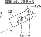
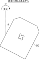
- the plurality of GPS antennas 12A and 12B are installed, for example, in the vehicle interior of the host vehicle 50 and are installed at a location different from the location to be measured (see FIG. 2).
- the positioning target location is the vehicle center and two GPS antennas 12A and 12B and receivers 14A and 14B are installed at the positions shown in FIG. 1, respectively.
- the distances of the respective GPS antennas 12A and 12B from the positioning target location can be accurately grasped by manually measuring.
- the receivers 14A and 14B are provided for the GPS antennas 12A and 12B, respectively, and the receivers 14A and 14B receive radio waves from a plurality of GPS satellites via the GPS antennas 12A and 12B and receive all of them. From the received signal from the GPS satellite, the satellite number of the GPS satellite, the orbit information (ephemeris) of the GPS satellite, the time when the GPS satellite transmitted radio waves, the strength of the received signal, the frequency, etc. are acquired as the information of the GPS satellite, and the computer is obtained. Output to 18.
- the attitude angle sensor 16 is, for example, a geomagnetic sensor and detects geomagnetism.
- the computer 18 includes a CPU, a ROM that stores a program for implementing a positioning processing routine described below, a RAM that temporarily stores data, and a storage device such as an HDD.
- GPS satellite information is acquired from all the receivers 14A and 14B for all GPS satellites that have received radio waves, and GPS pseudo range data and Doppler frequency are acquired.
- a satellite information acquisition unit 30 that calculates and acquires position coordinates of GPS satellites.
- the computer 18 includes an attitude angle calculation unit 32 that calculates the attitude angle of the host vehicle from the detection value of the attitude angle sensor 16.
- the computer 18 calculates the positional relationship between the GPS antenna installation location on the earth and the positioning target location for each of the GPS antennas 12A and 12B based on the calculated attitude angle of the host vehicle. Is equipped with.
- the computer 18 includes a position calculation unit 36 that calculates the position of the position to be measured on the earth using the calculated positional relationship and the acquired satellite information.
- the satellite information acquisition unit 30 acquires, from each of the receivers 14A and 14B, information about the GPS satellites for all GPS satellites that have received the radio waves, and also receives the time when the GPS satellites transmitted the radio waves and the radio waves in the vehicle. GPS pseudo distance data is calculated based on the time.
- the satellite information acquisition unit 30 respectively sets the Doppler frequency of the reception signal from each GPS satellite based on the known frequency of the signal transmitted from each GPS satellite and the frequency of the reception signal received from each GPS satellite. calculate.
- the Doppler frequency is an observation of the Doppler shift amount of the carrier frequency due to the relative speed between the GPS satellite and the vehicle.
- the satellite information acquisition unit 30 also calculates the position coordinates of the GPS satellites based on the orbit information of the GPS satellites and the time when the GPS satellites transmitted radio waves.
- the attitude angle calculation unit 32 calculates the attitude angle of the host vehicle at the time by using the detection value of the attitude angle sensor 16.
- the positional relationship calculation unit 34 detects, in advance, the distance between the installation location of each GPS antenna 12A, 12B and the positioning target location on the earth, the angle of the installation location of each GPS antenna 12A, 12B, and detection. Based on the determined attitude angle of the own vehicle, the absolute position relationship on the earth between the positioning target position (vehicle center) and each antenna installation position is calculated. Specifically, it is calculated by the following procedure. Here, a case where the GPS antenna 12A is targeted will be described.
- ⁇ is the long radius [m] of the earth
- f is the oblateness
- the position calculation unit 36 sets the position of the positioning target position and the time error of each of the plurality of GPS antennas 12A and 12B as unknowns, and determines the position of the positioning target position and the positioning target position (vehicle center) and each antenna installation position.
- a plurality of GPS antennas 12A and 12B are respectively described by using equations that describe the positions of the installation locations of the plurality of GPS antennas 12A and 12B using the relationship of the absolute position on the earth and the plurality of GPS antennas 12A and 12B.
- the position of the positioning target location is calculated based on the pseudo distance observed at the installation location.
- a total of 5 three-dimensional position vectors (x, y, z) in the ECEF coordinate system of the location to be measured and the time error between the two receivers 14A and 14B (hereinafter referred to as clock bias) Is an unknown number
- the three-dimensional position vectors in the ECEF coordinate system of the installation locations of the GPS antennas 12A and 12B are F A (x, y, z) and F B (x, y, z), respectively.
- formula (3) is established for each GPS antenna 12A, 12B and each satellite (here, only the GPS antenna 12A is described. The same applies to the GPS antenna 12B).
- the GPS antennas 12A and 12B are used to calculate the position (x, y, z) of the position to be measured by using the observation results of five or more satellites in total.
- the position (x, y, z) of the position to be measured is calculated by using the observation results of a total of (N+3) or more satellites.
- the position of the GPS antenna 12A is represented by the following formula.
- (x, y, z) is the position of the position to be measured
- Cb A is the clock bias [m] (converted to the distance by multiplying the speed of light) of the receiver 14A of the GPS antenna 12A.
- PR i is the pseudorange [m] observed for satellite i
- (X si , Y si , Z si ) is the position of satellite i.
- the position of the positioning target location can be accurately measured even when using the pseudo distance observed at a position different from the positioning target location. Can be calculated.
- the computer 18 executes a positioning processing routine shown in FIG. It is executed repeatedly.
- step S100 information on a plurality of GPS satellites is acquired from the GPS receivers 14A and 14B, and GPS pseudorange data, Doppler frequency, and position coordinates of the GPS satellites are calculated and acquired.
- GPS information for a plurality of GPS satellites acquired at the same time is acquired as a GPS information group.
- step S102 the attitude angle of the host vehicle is calculated based on the detection value from the attitude angle sensor 16.
- step S104 the distance between the installation location of each GPS antenna 12A, 12B on the earth and the location to be measured, the angle of the installation location of each GPS antenna 12A, 12B, which are obtained in advance, are detected. Based on the determined attitude angle of the own vehicle, the positional relationship in the ECEF coordinate system between the position to be positioned (vehicle center) and each antenna installation position is calculated.
- step S106 the position of the position to be measured and the time error of each of the plurality of GPS antennas 12A and 12B are set as unknowns, and the position of the position to be measured and the ECEF coordinates of the position to be measured (vehicle center) and each antenna installation position are set.
- the equation describing the positions of the installation locations of the plurality of GPS antennas 12A and 12B and the plurality of GPS antennas 12A and 12B are used to determine the location of each of the plurality of GPS antennas 12A and 12B.
- the position of the position measurement target position is calculated based on the observed pseudo distance, output by the output unit 20, and the process returns to step S100.
- the positioning device based on the detected attitude angle of the own vehicle, for each of the plurality of GPS antennas, the installation location of the GPS antenna on the earth, Calculate the positional relationship with the positioning target location.
- the positioning device uses the calculated positional relationship and the acquired satellite information to calculate the position of the position to be measured on the earth. This makes it possible to accurately calculate the position on the earth for a positioning target location different from the location where a plurality of GPS antennas are installed in the vehicle.
- the position and speed of the positioning target location can be accurately measured. Can be calculated.
- the number of satellites to be observed can be smaller than that when positioning is calculated independently for each GPS antenna. Moreover, since the position to be measured does not have to be the center of gravity of the installation location of the GPS antenna, the degree of freedom of the installation location of the GPS antenna is improved.
- the position of the positioning target in the ECEF coordinate system is calculated assuming that the installation positions of the plurality of GPS antennas are the same as the positioning target position.
- the difference from the first embodiment is mainly the point.
- the computer 218 of the positioning device 210 includes a satellite information acquisition unit 30, an attitude angle calculation unit 32, a reliability determination unit 232, and a positional relationship calculation unit 234. , And a position calculation unit 236.
- the reliability determination unit 232 determines the reliability of the attitude angle of the host vehicle calculated by the attitude angle calculation unit 32. Specifically, the reliability of the posture angle may be determined according to the traveling distance and the calculated variation of the posture angle. For example, the shorter the traveling distance, the lower the reliability of the posture angle is, or the posture angle is determined to be lower. The greater the fluctuation of, the lower the reliability of the posture angle may be determined to be.
- the positional relationship calculation unit 234 obtains each of the on-earth values obtained in advance, as in the first embodiment. Based on the distance between the installation location of the GPS antennas 12A and 12B and the positioning target location, the angle of the installation location of each GPS antenna 12A and 12B, and the detected attitude angle of the own vehicle, the positioning target location ( Calculate the absolute position on the earth between the center of the vehicle) and the location of each antenna.
- the reliability of the attitude angle determined by the reliability determination unit 232 is less than the threshold value, it is assumed that the installation locations of the GPS antennas 12A and 12B are the same as the positioning target location.
- the position calculation unit 236 calculates the position of the position to be positioned using the positional relationship calculated by the positional relationship calculation unit 234.
- the positional relationship calculated by the positional relationship calculation unit 234 is used to execute the first embodiment. Similarly to, the position of the position to be measured is calculated.
- the reliability of the attitude angle determined by the reliability determination unit 232 is less than the threshold value, it is determined that the installation locations of the GPS antennas 12A and 12B are the same as the positioning target location, and the positioning target in the ECEF coordinate system is determined. Calculate the position of a point. For example, the position of the positioning target location may be calculated based on the same idea as in Patent Document 2.
- the computer 218 executes the positioning processing routine shown in FIG. It is executed repeatedly.
- step S100 information on a plurality of GPS satellites is acquired from the GPS receivers 14A and 14B, and GPS pseudorange data, Doppler frequency, and position coordinates of the GPS satellites are calculated and acquired.
- GPS information for a plurality of GPS satellites acquired at the same time is acquired as a GPS information group.
- step S102 the attitude angle of the host vehicle is calculated based on the detection value from the attitude angle sensor 16.
- step S200 it is determined whether the reliability of the attitude angle of the host vehicle calculated in step S102 is equal to or more than a threshold value.
- step S104 the process proceeds to step S104, and the previously determined installation locations of the GPS antennas 12A and 12B on the earth and the positioning target location are determined. Based on the distance between the GPS antennas 12A and 12B, the position of each GPS antenna 12A and 12B, and the detected attitude angle of the vehicle, the ECEF coordinate system between the position to be positioned (vehicle center) and each antenna installation position. The positional relationship in is calculated.
- step S202 when the calculated reliability of the attitude angle of the own vehicle is less than the threshold value, the process proceeds to step S202, and it is assumed that the installation locations of the GPS antennas 12A and 12B are the same as the positioning target location.
- step S204 the position of the positioning target location is calculated using the installation location of the GPS antennas 12A and 12B obtained in step S104 or S202 and the positioning target location, and is output by the output unit 20 to the above step S100. Return.
- the positioning device of the second embodiment when the reliability of the detected attitude angle of the own vehicle is low, the installation location of the GPS antenna and the positioning target location are the same. Assuming that there is, the position of the positioning target point on the earth is calculated. As a result, it is possible to stably calculate the position on the earth for the position to be measured.
- a third embodiment a case where the present disclosure is applied to a speed measurement device that calculates the speed of the host vehicle will be described as an example.
- the same components as those of the positioning device 10 of the first embodiment are designated by the same reference numerals and the description thereof will be omitted.
- the velocity measuring device 310 includes a plurality of GPS antennas 12A and 12B, a plurality of receivers 14A and 14B, an attitude angle sensor 16, and a gyro sensor 316. I have it.
- the speed measurement device 310 estimates the speed of the host vehicle based on the received signals from the GPS satellites received by the plurality of receivers 14A and 14B and the detection values of the attitude angle sensor 16 and the gyro sensor 316.
- the computer 318 for executing the above and the output unit 20 are provided.
- a satellite information acquisition unit 30 an attitude angle calculation unit 32, an angular velocity calculation unit 332 that calculates the angular velocity of the host vehicle from the detection value of the gyro sensor 316, Is equipped with.
- the computer 318 calculates the speed relationship between the GPS antenna installation location and the positioning target location on the earth for each of the GPS antennas 12A and 12B based on the calculated attitude angle and angular velocity of the vehicle. It includes a unit 334, a speed calculation unit 336 that calculates the speed of the position to be measured on the earth by using the calculated speed relationship and the acquired satellite information.
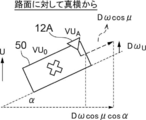
- the speed relation calculation unit 334 detects the distance between the installation location of each GPS antenna 12A and 12B on the earth and the positioning target location, the angle of the installation location of each GPS antenna 12A and 12B, which is obtained in advance, and detects the location. Based on the determined attitude angle and angular velocity of the own vehicle, the speed relationship on the earth between the position to be positioned (vehicle center) and each antenna installation position is calculated. Specifically, it is calculated by the following procedure. Here, a case where the GPS antenna 12A is targeted will be described.
- ⁇ is the long radius [m] of the earth
- f is the oblateness
- the speed calculation unit 336 sets the speed of the positioning target location and the time error of each of the plurality of GPS antennas 12A and 12B as unknowns, and determines the speed of the positioning target location and the positioning target location (vehicle center) and each antenna installation location.
- the velocity of the location to be positioned is calculated based on the relative velocity with the satellite obtained from the Doppler frequency observed at the location.
- the three-dimensional velocity vector (Vx, Vy, Vz) in the ECEF coordinate system of the position to be measured and the change amount of the clock bias of the two receivers 14A and 14B (hereinafter, referred to as clock drift)
- clock drift the change amount of the clock bias of the two receivers 14A and 14B
- the three-dimensional velocity vector in the ECEF coordinate system of the installation location of each GPS antenna 12A, 12B is set to G A (Vx, Vy, Vz) and G B (Vx, Vy, Vz).
- G A Vx, Vy, Vz
- G B Vx, Vy, Vz
- the speed (Vx, Vy, Vz) of the position to be measured is calculated using the observation results of a total of five or more satellites of the GPS antennas 12A and 12B.
- the speed (Vx, Vy, Vz) of the positioning target location is calculated using the observation results by a total of (N+3) or more satellites.
- the speed of the GPS antenna 12A is represented by the following formula.
- (Vx, Vy, Vz) is the speed of the position to be measured
- Cbv A is the clock drift [m/s] (converted to the speed by multiplying the speed of light) of the receiver 14A of the GPS antenna 12A.
- (X A , y A , z A ) is the position of the GPS antenna 12A.
- D i is the Doppler frequency [Hz] observed for the satellite i
- (X si , Y si , Z si ) is the position of the satellite i
- r i is represented by the following formula.
- f 1 is the carrier frequency (1575.42 ⁇ 10 6 ) [Hz]
- C is the speed of light (2.99792458 ⁇ 10 8 ) [m/s]
- (V xsi , V ysi , V zsi ) is the satellite i is the speed.
- the speed of the positioning target location can be accurately measured. Can be calculated.
- the attitude angle sensor 16 detects geomagnetism
- the gyro sensor 316 detects angular acceleration
- the GPS antennas 12A and 12B and the receivers 14A and 14B receive radio waves from a plurality of GPS satellites.
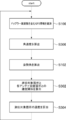
- the computer 318 repeatedly executes the speed measurement processing routine shown in FIG.
- step S100 information on a plurality of GPS satellites is acquired from the GPS receivers 14A and 14B, and GPS pseudorange data, Doppler frequency, and position coordinates of the GPS satellites are calculated and acquired.
- GPS information for a plurality of GPS satellites acquired at the same time is acquired as a GPS information group.
- step S300 the angular velocity of the host vehicle is calculated based on the detection value from the gyro sensor 316. Then, in step S102, the attitude angle of the host vehicle is calculated based on the detection value from the attitude angle sensor 16.
- step S302 the distance between the installation location of each GPS antenna 12A, 12B on the earth and the location to be measured, the angle of the installation location of each GPS antenna 12A, 12B, which are obtained in advance, and detection are performed. Based on the determined attitude angle and angular velocity of the own vehicle, the speed relationship on the earth between the position to be positioned (vehicle center) and each antenna installation position is calculated.
- step S304 the velocity of the positioning target location and the time error of each of the plurality of GPS antennas 12A and 12B are set as unknowns, and the velocity of the positioning target location and the earth between the positioning target location (vehicle center) and each antenna installation location Using the above speed relationship, the equation describing the speed of the installation location of the plurality of GPS antennas 12A, 12B and the plurality of GPS antennas 12A, 12B Based on the relative velocity with the satellite obtained from the observed Doppler frequency, the velocity of the position to be positioned is calculated, output by the output unit 20, and the process returns to step S100.
- the speed measuring device calculates the speed of the position to be measured on the earth using the calculated speed relationship and the acquired satellite information. As a result, the speed on the earth can be accurately calculated for the position to be positioned different from the position where the plurality of GPS antennas are installed in the vehicle.
- the computer 418 of the velocity measurement device 410 includes a satellite information acquisition unit 30, an attitude angle calculation unit 32, an angular velocity calculation unit 332, and a reliability determination unit 432.
- a speed relationship calculation unit 434 and a speed calculation unit 436 are provided.
- the reliability determination unit 432 determines the reliability of the attitude angle of the own vehicle calculated by the attitude angle calculation unit 32 and the angular velocity of the own vehicle calculated by the angular velocity calculation unit 332. Specifically, the reliability of the posture angle and the angular velocity may be determined according to the traveling distance and the calculated variation of the posture angle and the variation of the angular velocity. For example, the reliability of the attitude angle and the angular velocity may be determined to be lower as the traveling distance is shorter, or the reliability of the attitude angle and the angular velocity may be determined to be lower as the variation of the attitude angle and the angular velocity are greater.
- the velocity relationship calculation unit 434 obtains the previously-obtained Based on the distance between the installation location of each GPS antenna 12A, 12B and the position to be measured, the angle of the installation location of each GPS antenna 12A, 12B, and the detected attitude angle and angular velocity of the own vehicle, Calculate the speed relationship on the earth between the position to be positioned (vehicle center) and each antenna installation position.
- the reliability of the posture angle and the angular velocity determined by the reliability determination unit 432 is less than the threshold value, it is assumed that the speeds of the installation locations of the GPS antennas 12A and 12B and the positioning target location are the same.
- the speed calculation unit 436 calculates the speed of the positioning target location using the speed relationship calculated by the speed relationship calculation unit 434.
- the velocity relation calculated by the velocity relation calculation unit 434 is used to perform the first embodiment. In the same manner as in the above form, the speed of the location subject to positioning is calculated.
- the reliability of the posture angle and the angular velocity determined by the reliability determination unit 432 is less than the threshold value, it is determined that the speeds of the installation locations of the GPS antennas 12A and 12B and the positioning target location are the same, and the ECEF coordinates Calculate the velocity of the position to be measured in the system.
- the speed of the positioning target location may be calculated based on the same idea as in Non-Patent Document 1 above.
- the velocity measuring device when the reliability of the detected attitude angle and angular velocity of the own vehicle is low, the GPS antenna installation location and the positioning target location Assuming that the velocities are the same, the velocities of the positioning target points on the earth are calculated. As a result, the speed on the earth can be stably calculated for the position to be positioned.
- the positioning device or the speed measuring device mounted on the vehicle has been described as an example, but the moving body on which the positioning device or the speed measuring device of the present disclosure is mounted. Is not limited to vehicles.
- the positioning device or the speed measuring device may be mounted on the robot.
- GPS is used as the satellite navigation system
- other satellite positioning systems GLONASS, BeiDou, Galileo, QZSS
- GLONASS BeiDou, Galileo, QZSS
Landscapes
- Engineering & Computer Science (AREA)
- Radar, Positioning & Navigation (AREA)
- Remote Sensing (AREA)
- Physics & Mathematics (AREA)
- General Physics & Mathematics (AREA)
- Computer Networks & Wireless Communication (AREA)
- Position Fixing By Use Of Radio Waves (AREA)
Priority Applications (1)
| Application Number | Priority Date | Filing Date | Title |
|---|---|---|---|
| US17/328,474 US12013467B2 (en) | 2018-11-26 | 2021-05-24 | Positioning device, speed measuring device, and computer program product |
Applications Claiming Priority (2)
| Application Number | Priority Date | Filing Date | Title |
|---|---|---|---|
| JP2018220142A JP7201219B2 (ja) | 2018-11-26 | 2018-11-26 | 測位装置、速度測定装置、及びプログラム |
| JP2018-220142 | 2018-11-26 |
Related Child Applications (1)
| Application Number | Title | Priority Date | Filing Date |
|---|---|---|---|
| US17/328,474 Continuation US12013467B2 (en) | 2018-11-26 | 2021-05-24 | Positioning device, speed measuring device, and computer program product |
Publications (1)
| Publication Number | Publication Date |
|---|---|
| WO2020110996A1 true WO2020110996A1 (ja) | 2020-06-04 |
Family
ID=70853480
Family Applications (1)
| Application Number | Title | Priority Date | Filing Date |
|---|---|---|---|
| PCT/JP2019/045962 Ceased WO2020110996A1 (ja) | 2018-11-26 | 2019-11-25 | 測位装置、速度測定装置、及びプログラム |
Country Status (3)
| Country | Link |
|---|---|
| US (1) | US12013467B2 (https=) |
| JP (1) | JP7201219B2 (https=) |
| WO (1) | WO2020110996A1 (https=) |
Cited By (1)
| Publication number | Priority date | Publication date | Assignee | Title |
|---|---|---|---|---|
| CN112327250A (zh) * | 2020-10-30 | 2021-02-05 | 杭州海康威视数字技术股份有限公司 | 一种目标定位方法及系统、定位节点 |
Families Citing this family (1)
| Publication number | Priority date | Publication date | Assignee | Title |
|---|---|---|---|---|
| JP7140443B2 (ja) * | 2019-07-10 | 2022-09-21 | 株式会社豊田中央研究所 | アンテナ間相対位置推定方法及びアンテナ間相対位置推定プログラム |
Citations (2)
| Publication number | Priority date | Publication date | Assignee | Title |
|---|---|---|---|---|
| JP3178938U (ja) * | 2012-06-25 | 2012-10-11 | 健二 井澗 | 衛星測位装置 |
| JP2015025671A (ja) * | 2013-07-24 | 2015-02-05 | 古野電気株式会社 | 状態算出装置、移動体、状態算出方法、および状態算出プログラム |
Family Cites Families (5)
| Publication number | Priority date | Publication date | Assignee | Title |
|---|---|---|---|---|
| JPS61224703A (ja) * | 1985-03-29 | 1986-10-06 | Aisin Seiki Co Ltd | 移動体上アンテナの姿勢制御装置 |
| JPH02196975A (ja) | 1989-01-26 | 1990-08-03 | Nissan Motor Co Ltd | 車両用gps航法装置 |
| JPH04174385A (ja) * | 1990-11-06 | 1992-06-22 | Aisin Seiki Co Ltd | 移動体上アンテナの姿勢制御装置 |
| JP4840323B2 (ja) * | 2007-10-05 | 2011-12-21 | 株式会社デンソー | 衛星測位用受信装置 |
| JP2009145283A (ja) | 2007-12-18 | 2009-07-02 | Mitsubishi Electric Corp | 測位装置 |
-
2018
- 2018-11-26 JP JP2018220142A patent/JP7201219B2/ja active Active
-
2019
- 2019-11-25 WO PCT/JP2019/045962 patent/WO2020110996A1/ja not_active Ceased
-
2021
- 2021-05-24 US US17/328,474 patent/US12013467B2/en active Active
Patent Citations (2)
| Publication number | Priority date | Publication date | Assignee | Title |
|---|---|---|---|---|
| JP3178938U (ja) * | 2012-06-25 | 2012-10-11 | 健二 井澗 | 衛星測位装置 |
| JP2015025671A (ja) * | 2013-07-24 | 2015-02-05 | 古野電気株式会社 | 状態算出装置、移動体、状態算出方法、および状態算出プログラム |
Cited By (2)
| Publication number | Priority date | Publication date | Assignee | Title |
|---|---|---|---|---|
| CN112327250A (zh) * | 2020-10-30 | 2021-02-05 | 杭州海康威视数字技术股份有限公司 | 一种目标定位方法及系统、定位节点 |
| CN112327250B (zh) * | 2020-10-30 | 2024-05-03 | 杭州海康威视数字技术股份有限公司 | 一种目标定位方法及系统、定位节点 |
Also Published As
| Publication number | Publication date |
|---|---|
| JP7201219B2 (ja) | 2023-01-10 |
| US20210286084A1 (en) | 2021-09-16 |
| US12013467B2 (en) | 2024-06-18 |
| JP2020085650A (ja) | 2020-06-04 |
Similar Documents
| Publication | Publication Date | Title |
|---|---|---|
| CN111801596B (zh) | 用于测定一车辆天线校正信息的方法和装置 | |
| CN111989594B (zh) | 用于测定一车辆位置的方法 | |
| JP5673071B2 (ja) | 位置推定装置及びプログラム | |
| JP4781313B2 (ja) | マルチパス検出装置、測位装置、姿勢方位標定装置、マルチパス検出方法およびマルチパス検出プログラム | |
| JP5554560B2 (ja) | 測位信頼度評価装置、測位信頼度評価方法、および、測位信頼度評価プログラム | |
| US10732299B2 (en) | Velocity estimation device | |
| JP7111298B2 (ja) | 衛星選択装置、及びプログラム | |
| US10809390B2 (en) | Positioning apparatus | |
| WO2017029042A1 (en) | Antenna pattern data mining for automotive global navigation satellite system receivers | |
| JP2014077769A (ja) | センサ傾斜判定装置及びプログラム | |
| JP2012203721A (ja) | 相対位置推定装置及びプログラム | |
| US20070040737A1 (en) | Apparatus and method for carrier phase-based relative positioning | |
| JP2012098185A (ja) | 方位角推定装置及びプログラム | |
| JP2010256301A (ja) | マルチパス判定装置及びプログラム | |
| JP2013228318A (ja) | キャリブレーション良否判定装置及び方法 | |
| US12013467B2 (en) | Positioning device, speed measuring device, and computer program product | |
| JP7140443B2 (ja) | アンテナ間相対位置推定方法及びアンテナ間相対位置推定プログラム | |
| JP7148039B2 (ja) | 移動体情報推定装置及びプログラム | |
| JP2010223684A (ja) | 移動体用測位装置 | |
| CN110869808A (zh) | 方位推定装置 | |
| JP2010112759A (ja) | 移動体位置測位装置 | |
| JP4518096B2 (ja) | 移動体測位装置 | |
| JP7789266B2 (ja) | 位置姿勢標定装置、位置姿勢標定方法、及び位置姿勢標定プログラム | |
| JP5062141B2 (ja) | 移動体用測位装置 | |
| CN114008487B (zh) | 通过运动预测进行误差和完整性评估 |
Legal Events
| Date | Code | Title | Description |
|---|---|---|---|
| 121 | Ep: the epo has been informed by wipo that ep was designated in this application |
Ref document number: 19890447 Country of ref document: EP Kind code of ref document: A1 |
|
| NENP | Non-entry into the national phase |
Ref country code: DE |
|
| 122 | Ep: pct application non-entry in european phase |
Ref document number: 19890447 Country of ref document: EP Kind code of ref document: A1 |