WO2020110979A1 - 排気浄化装置および車両 - Google Patents
排気浄化装置および車両 Download PDFInfo
- Publication number
- WO2020110979A1 WO2020110979A1 PCT/JP2019/045925 JP2019045925W WO2020110979A1 WO 2020110979 A1 WO2020110979 A1 WO 2020110979A1 JP 2019045925 W JP2019045925 W JP 2019045925W WO 2020110979 A1 WO2020110979 A1 WO 2020110979A1
- Authority
- WO
- WIPO (PCT)
- Prior art keywords
- reducing agent
- exhaust
- selective reduction
- exhaust gas
- reduction catalyst
- Prior art date
- Legal status (The legal status is an assumption and is not a legal conclusion. Google has not performed a legal analysis and makes no representation as to the accuracy of the status listed.)
- Ceased
Links
Images


Classifications
-
- B—PERFORMING OPERATIONS; TRANSPORTING
- B01—PHYSICAL OR CHEMICAL PROCESSES OR APPARATUS IN GENERAL
- B01D—SEPARATION
- B01D53/00—Separation of gases or vapours; Recovering vapours of volatile solvents from gases; Chemical or biological purification of waste gases, e.g. engine exhaust gases, smoke, fumes, flue gases, aerosols
- B01D53/34—Chemical or biological purification of waste gases
- B01D53/92—Chemical or biological purification of waste gases of engine exhaust gases
- B01D53/94—Chemical or biological purification of waste gases of engine exhaust gases by catalytic processes
- B01D53/9481—Catalyst preceded by an adsorption device without catalytic function for temporary storage of contaminants, e.g. during cold start
-
- B—PERFORMING OPERATIONS; TRANSPORTING
- B01—PHYSICAL OR CHEMICAL PROCESSES OR APPARATUS IN GENERAL
- B01D—SEPARATION
- B01D53/00—Separation of gases or vapours; Recovering vapours of volatile solvents from gases; Chemical or biological purification of waste gases, e.g. engine exhaust gases, smoke, fumes, flue gases, aerosols
- B01D53/34—Chemical or biological purification of waste gases
- B01D53/92—Chemical or biological purification of waste gases of engine exhaust gases
- B01D53/94—Chemical or biological purification of waste gases of engine exhaust gases by catalytic processes
- B01D53/9404—Removing only nitrogen compounds
- B01D53/9409—Nitrogen oxides
-
- F—MECHANICAL ENGINEERING; LIGHTING; HEATING; WEAPONS; BLASTING
- F01—MACHINES OR ENGINES IN GENERAL; ENGINE PLANTS IN GENERAL; STEAM ENGINES
- F01N—GAS-FLOW SILENCERS OR EXHAUST APPARATUS FOR MACHINES OR ENGINES IN GENERAL; GAS-FLOW SILENCERS OR EXHAUST APPARATUS FOR INTERNAL-COMBUSTION ENGINES
- F01N3/00—Exhaust or silencing apparatus having means for purifying, rendering innocuous, or otherwise treating exhaust
- F01N3/08—Exhaust or silencing apparatus having means for purifying, rendering innocuous, or otherwise treating exhaust for rendering innocuous
- F01N3/10—Exhaust or silencing apparatus having means for purifying, rendering innocuous, or otherwise treating exhaust for rendering innocuous by thermal or catalytic conversion of noxious components of exhaust
- F01N3/18—Exhaust or silencing apparatus having means for purifying, rendering innocuous, or otherwise treating exhaust for rendering innocuous by thermal or catalytic conversion of noxious components of exhaust characterised by methods of operation; Control
- F01N3/20—Exhaust or silencing apparatus having means for purifying, rendering innocuous, or otherwise treating exhaust for rendering innocuous by thermal or catalytic conversion of noxious components of exhaust characterised by methods of operation; Control specially adapted for catalytic conversion
- F01N3/206—Adding periodically or continuously substances to exhaust gases for promoting purification, e.g. catalytic material in liquid form, NOx reducing agents
- F01N3/2066—Selective catalytic reduction [SCR]
-
- F—MECHANICAL ENGINEERING; LIGHTING; HEATING; WEAPONS; BLASTING
- F01—MACHINES OR ENGINES IN GENERAL; ENGINE PLANTS IN GENERAL; STEAM ENGINES
- F01N—GAS-FLOW SILENCERS OR EXHAUST APPARATUS FOR MACHINES OR ENGINES IN GENERAL; GAS-FLOW SILENCERS OR EXHAUST APPARATUS FOR INTERNAL-COMBUSTION ENGINES
- F01N3/00—Exhaust or silencing apparatus having means for purifying, rendering innocuous, or otherwise treating exhaust
- F01N3/08—Exhaust or silencing apparatus having means for purifying, rendering innocuous, or otherwise treating exhaust for rendering innocuous
- F01N3/10—Exhaust or silencing apparatus having means for purifying, rendering innocuous, or otherwise treating exhaust for rendering innocuous by thermal or catalytic conversion of noxious components of exhaust
- F01N3/24—Exhaust or silencing apparatus having means for purifying, rendering innocuous, or otherwise treating exhaust for rendering innocuous by thermal or catalytic conversion of noxious components of exhaust characterised by constructional aspects of converting apparatus
- F01N3/28—Construction of catalytic reactors
- F01N3/2892—Exhaust flow directors or the like, e.g. upstream of catalytic device
-
- B—PERFORMING OPERATIONS; TRANSPORTING
- B01—PHYSICAL OR CHEMICAL PROCESSES OR APPARATUS IN GENERAL
- B01D—SEPARATION
- B01D2251/00—Reactants
- B01D2251/20—Reductants
- B01D2251/206—Ammonium compounds
- B01D2251/2067—Urea
-
- B—PERFORMING OPERATIONS; TRANSPORTING
- B01—PHYSICAL OR CHEMICAL PROCESSES OR APPARATUS IN GENERAL
- B01D—SEPARATION
- B01D2258/00—Sources of waste gases
- B01D2258/01—Engine exhaust gases
- B01D2258/012—Diesel engines and lean burn gasoline engines
-
- F—MECHANICAL ENGINEERING; LIGHTING; HEATING; WEAPONS; BLASTING
- F01—MACHINES OR ENGINES IN GENERAL; ENGINE PLANTS IN GENERAL; STEAM ENGINES
- F01N—GAS-FLOW SILENCERS OR EXHAUST APPARATUS FOR MACHINES OR ENGINES IN GENERAL; GAS-FLOW SILENCERS OR EXHAUST APPARATUS FOR INTERNAL-COMBUSTION ENGINES
- F01N2240/00—Combination or association of two or more different exhaust treating devices, or of at least one such device with an auxiliary device, not covered by indexing codes F01N2230/00 or F01N2250/00, one of the devices being
- F01N2240/20—Combination or association of two or more different exhaust treating devices, or of at least one such device with an auxiliary device, not covered by indexing codes F01N2230/00 or F01N2250/00, one of the devices being a flow director or deflector
-
- F—MECHANICAL ENGINEERING; LIGHTING; HEATING; WEAPONS; BLASTING
- F01—MACHINES OR ENGINES IN GENERAL; ENGINE PLANTS IN GENERAL; STEAM ENGINES
- F01N—GAS-FLOW SILENCERS OR EXHAUST APPARATUS FOR MACHINES OR ENGINES IN GENERAL; GAS-FLOW SILENCERS OR EXHAUST APPARATUS FOR INTERNAL-COMBUSTION ENGINES
- F01N2610/00—Adding substances to exhaust gases
- F01N2610/02—Adding substances to exhaust gases the substance being ammonia or urea
-
- Y—GENERAL TAGGING OF NEW TECHNOLOGICAL DEVELOPMENTS; GENERAL TAGGING OF CROSS-SECTIONAL TECHNOLOGIES SPANNING OVER SEVERAL SECTIONS OF THE IPC; TECHNICAL SUBJECTS COVERED BY FORMER USPC CROSS-REFERENCE ART COLLECTIONS [XRACs] AND DIGESTS
- Y02—TECHNOLOGIES OR APPLICATIONS FOR MITIGATION OR ADAPTATION AGAINST CLIMATE CHANGE
- Y02A—TECHNOLOGIES FOR ADAPTATION TO CLIMATE CHANGE
- Y02A50/00—TECHNOLOGIES FOR ADAPTATION TO CLIMATE CHANGE in human health protection, e.g. against extreme weather
- Y02A50/20—Air quality improvement or preservation, e.g. vehicle emission control or emission reduction by using catalytic converters
-
- Y—GENERAL TAGGING OF NEW TECHNOLOGICAL DEVELOPMENTS; GENERAL TAGGING OF CROSS-SECTIONAL TECHNOLOGIES SPANNING OVER SEVERAL SECTIONS OF THE IPC; TECHNICAL SUBJECTS COVERED BY FORMER USPC CROSS-REFERENCE ART COLLECTIONS [XRACs] AND DIGESTS
- Y02—TECHNOLOGIES OR APPLICATIONS FOR MITIGATION OR ADAPTATION AGAINST CLIMATE CHANGE
- Y02T—CLIMATE CHANGE MITIGATION TECHNOLOGIES RELATED TO TRANSPORTATION
- Y02T10/00—Road transport of goods or passengers
- Y02T10/10—Internal combustion engine [ICE] based vehicles
- Y02T10/12—Improving ICE efficiencies
Definitions
- the present disclosure relates to an exhaust emission control device and a vehicle.
- reducing agent solid a solid
- An object of the present disclosure is to provide an exhaust emission control device and a vehicle capable of suppressing the catalyst of a selective reduction catalyst from being scraped off into a reducing agent solid matter, and thus suppressing reduction in exhaust gas purification efficiency. It is to be.
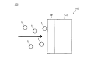
- FIG. 1 is a schematic configuration diagram showing an exhaust system of an internal combustion engine 1 to which an exhaust emission control device 100 according to an embodiment of the present disclosure is applied.
- the internal combustion engine 1 is a diesel engine mounted on a vehicle V, for example.
- the internal combustion engine 1 is provided with an exhaust gas purification device 100 for introducing exhaust gas generated in the internal combustion engine 1 into the atmosphere.
- the exhaust gas purification device 100 includes an exhaust pipe 110, a reducing agent supply unit 120, a mixing unit 130, a selective reduction catalyst 140, and a blocking unit 150.
- Exhaust gas generated from the internal combustion engine 1 flows through the exhaust pipe 110.
- the reducing agent supply unit 120, the mixing unit 130, the blocking unit 150, and the selective reduction are sequentially arranged from the upstream side in the direction in which the exhaust gas flows (the direction from the left to the right in the drawing, hereinafter referred to as the “exhaust direction”).
- a mold catalyst 140 and the like are provided.
- the reducing agent supply unit 120 supplies a reducing agent (urea water) for producing ammonia to the exhaust pipe 110.
- a reducing agent urea water
- the reducing agent is supplied into the exhaust pipe 110 by the reducing agent supply unit 120, the reducing agent is hydrolyzed by the temperature in the exhaust pipe 110 to generate ammonia.
- the mixing unit 130 is provided in the exhaust pipe 110 after the reducing agent supply unit 120 and mixes the exhaust gas and the reducing agent.
- the base body 142 has a structure such as a honeycomb structure in which a catalyst 141 is carried on an upstream end face in the exhaust direction and a passage hole through which exhaust gas can pass is formed.
- the selective reduction catalyst 140 adsorbs ammonia generated based on the reducing agent supplied by the reducing agent supply unit 120.
- the selective reduction catalyst 140 reduces the nitrogen oxides by reacting the adsorbed ammonia with the nitrogen oxides contained in the exhaust gas passing therethrough.
- the shutoff unit 150 is arranged between the reducing agent supply unit 120 and the selective reduction catalyst 140 in the exhaust pipe 110 and apart from the selective reduction catalyst 140.
- the blocking unit 150 has the same structure as that of the base body 142, and is configured to allow exhaust gas to pass therethrough similarly to the base body 142.
- the blocking unit 150 blocks the transfer of the reducing agent solids to the selective reduction catalyst 140 when the reducing agent solids flow in the exhaust pipe 110 together with the exhaust gas.
- Exhaust gas is in a relatively low temperature when the internal combustion engine 1 is operating at a low load. Further, the amount of the reducing agent supplied by the reducing agent supply unit 120 becomes excessively large when there is some trouble such as a sensor failure in the control system that controls the reducing agent supply amount. ..
- the reason why the reducing agent becomes a solid reducing agent without evaporating is that when the reducing agent solidifies without vaporizing due to the low temperature state of the exhaust gas, the mixing by the mixing unit 130 is insufficient. Then, the case where the reducing agent is solidified is included.
- the mixing by the mixing unit 130 is insufficient when the reducing agent and the exhaust gas are not properly mixed due to the performance of the mixing unit 130, or when the reducing agent from the reducing agent supply unit 120 is in the mixing unit 130. There is a case where it is not supplied properly.
- the solid reducing agent produced in this way moves downstream in the exhaust direction due to the flow of exhaust gas.
- the exhaust emission control device 100 does not have the cutoff portion 150
- the catalyst carried on the end surface of the substrate 142. 141 is contacted.
- the catalyst 141 is scraped off by the reducing agent solids S, and the amount of the catalyst 141 in the selective reduction catalyst 140 decreases, so that the exhaust gas purification efficiency of the exhaust emission control device 100 decreases. .. Further, depending on the material of the base body 142, the base material 142 is scraped together with the catalyst 141 by the reducing agent solid matter S, so that the selective reduction catalyst 140 may be damaged.
- the blocking unit 150 blocks the reducing agent solid S from moving to the selective reduction catalyst 140.
- the reducing agent solid S does not move to the selective reduction catalyst 140, so that the catalyst 141 of the selective reducing catalyst 140 can be prevented from being scraped off by the reducing solid S.
- the blocking section 150 becomes a resistance to the flow of exhaust gas, which may cause a pressure loss. More specifically, since the blocking unit 150 and the base body 142 have the same structure, the presence of the blocking unit 150 becomes a resistance to the flow of exhaust gas unless the exhaust gas passage holes are aligned. As a result, pressure loss may occur. Further, when the selective reduction catalyst 140 and the blocking unit 150 are inserted into the exhaust pipe 110 during manufacturing of the exhaust purification device 100, the blocking unit 150 may peel off the catalyst 141 of the selective reduction catalyst 140, or depending on the material of the substrate 142. The selective reduction catalyst 140 may be damaged.
- the blocking unit 150 is separated from the selective reduction catalyst 140, it is possible to prevent the above problems from occurring. Further, since it is not necessary to align the passage hole of the blocking portion 150 and the passage hole of the base body 142, the process of assembling the exhaust emission control device 100 can be simplified. Further, from the viewpoint of suppressing the occurrence of the above problem, it is preferable that the blocking unit 150 be separated from the selective reduction catalyst 140 as much as possible. Further, as long as the above problem can be solved, the blocking unit 150 may be placed in contact with the selective reduction catalyst 140.
- the blocking portion 150 is formed of a material harder than the reducing agent solid S, even if the reducing agent solid S contacts the blocking portion 150, the blocking portion 150 is crushed by the reducing agent solid S. Will not be lost. As a result, the effect of the blocking unit 150 can be maintained.
- the blocking unit 150 since the blocking unit 150 is not crushed by the reducing agent solid S, the blocking unit 150 can be made relatively thin, which can contribute to downsizing of the entire apparatus.
- the blocking unit 150 is arranged apart from the selective reduction catalyst 140, but the present disclosure is not limited to this.
- the present disclosure is not limited to this.
- the present disclosure may be integrated with the base 143 of the die catalyst 140.
- the base body 143 in this configuration has an upstream region 143A on the upstream side in the exhaust direction and a downstream region 143B on the downstream side in the exhaust direction.
- the upstream region 143A is a non-carrying region that constitutes a blocking portion and does not carry a catalyst
- the downstream region 143B is a carrying region that carries a catalyst. That is, the blocking portion is located upstream of the carrying region in the exhaust direction.
- the blocking unit can prevent the reducing agent solid matter from reaching the loading area, which is the area where the catalyst is loaded.
- the blocking portion (upstream region 143A) and the carrying region (downstream region 143B) are integrated, in the process of assembling the exhaust gas purification device 100, the blocking portion and the carrying region are disposed inside the exhaust pipe 110 only by the step of disposing the base 143. Can be placed at. As a result, the process of assembling the exhaust emission control device 100 can be simplified.
Landscapes
- Chemical & Material Sciences (AREA)
- Engineering & Computer Science (AREA)
- Chemical Kinetics & Catalysis (AREA)
- Combustion & Propulsion (AREA)
- Health & Medical Sciences (AREA)
- General Chemical & Material Sciences (AREA)
- Mechanical Engineering (AREA)
- General Engineering & Computer Science (AREA)
- Biomedical Technology (AREA)
- Environmental & Geological Engineering (AREA)
- Analytical Chemistry (AREA)
- Toxicology (AREA)
- Oil, Petroleum & Natural Gas (AREA)
- Materials Engineering (AREA)
- Exhaust Gas Treatment By Means Of Catalyst (AREA)
- Exhaust Gas After Treatment (AREA)
Abstract
排気浄化装置は、内燃機関で発生した排気ガスが流れる排気管と、排気管に設けられ、排気ガス中の窒素酸化物の還元を促進する選択還元型触媒と、排気管における選択還元型触媒の前段に設けられ、排気ガス中の窒素酸化物を還元する還元剤を供給する還元剤供給部と、排気管における還元剤供給部と選択還元型触媒との間に設けられ、還元剤固形物が排気ガスとともに排気管内を流れた場合に還元剤固形物の前記選択還元型触媒への移動を遮断する遮断部と、を備える。
Description
本開示は、排気浄化装置および車両に関する。
従来、内燃機関の排気浄化装置では、尿素水等の還元剤によりアンモニアを生成し、選択還元型触媒を用いて当該アンモニアと排気ガス中の窒素酸化物との還元作用を促進する構成が知られている(例えば、特許文献1参照)。還元剤は、排気管における選択還元型触媒の前段に設けられる噴射装置等により、排気管内に供給される。
しかしながら、内燃機関の低負荷動作時等において、排気ガスが比較的低温の状態になったり、供給された還元剤の量が過剰に多くなると、排気管内で還元剤が蒸発せずに、凝固して固形物(以下、「還元剤固形物」)となる場合がある。
この還元剤固形物が排気ガスとともに選択還元型触媒まで到達すると、選択還元型触媒に接触する。還元剤固形物が選択還元型触媒に接触すると、選択還元型触媒を構成する触媒担持体上の触媒が還元剤固形物により削り落とされ、ひいては、排気浄化装置における排気ガスの浄化効率が低下するおそれがある。
本開示の目的は、選択還元型触媒の触媒が還元剤固形物に削り落とされることを抑制し、ひいては排気ガスの浄化効率が低下することを抑制することが可能な排気浄化装置および車両を提供することである。
本開示に係る排気浄化装置は、
内燃機関で発生した排気ガスが流れる排気管と、
前記排気管に設けられ、前記排気ガス中の窒素酸化物の還元を促進する選択還元型触媒と、
前記排気管における前記選択還元型触媒の前段に設けられ、前記排気ガス中の前記窒素酸化物を還元する還元剤を供給する還元剤供給部と、
前記排気管における前記還元剤供給部と前記選択還元型触媒との間に設けられ、還元剤固形物が前記排気ガスとともに前記排気管内を流れた場合に前記還元剤固形物の前記選択還元型触媒への移動を遮断する遮断部と、
を備える。
内燃機関で発生した排気ガスが流れる排気管と、
前記排気管に設けられ、前記排気ガス中の窒素酸化物の還元を促進する選択還元型触媒と、
前記排気管における前記選択還元型触媒の前段に設けられ、前記排気ガス中の前記窒素酸化物を還元する還元剤を供給する還元剤供給部と、
前記排気管における前記還元剤供給部と前記選択還元型触媒との間に設けられ、還元剤固形物が前記排気ガスとともに前記排気管内を流れた場合に前記還元剤固形物の前記選択還元型触媒への移動を遮断する遮断部と、
を備える。
本開示に係る車両は、
上記の排気浄化装置を備える。
上記の排気浄化装置を備える。
本開示によれば、選択還元型触媒の触媒が還元剤固形物に削り落とされることを抑制し、ひいては排気ガスの浄化効率が低下することを抑制することができる。
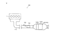
以下、本開示の実施の形態を図面に基づいて詳細に説明する。図1は、本開示の実施の形態に係る排気浄化装置100が適用された内燃機関1の排気系を示す概略構成図である。
図1に示すように、内燃機関1は、車両Vに搭載される、例えばディーゼルエンジンである。内燃機関1には、内燃機関1で生じた排気ガスを大気中に導くための排気浄化装置100が設けられている。排気浄化装置100は、排気管110と、還元剤供給部120と、混合部130と、選択還元型触媒140と、遮断部150とを備えている。
排気管110では、内燃機関1から生じた排気ガスが流れる。排気管110には、排気ガスが流れる方向(図示左から右へ向かう方向、以下、「排気方向」という)の上流側から順に、還元剤供給部120、混合部130、遮断部150、選択還元型触媒140等が設けられている。
還元剤供給部120は、アンモニアを生成するための還元剤(尿素水)を排気管110に供給する。還元剤供給部120により、還元剤が排気管110内に供給されると、排気管110内の温度により還元剤が加水分解されて、アンモニアが生成される。
混合部130は、排気管110における還元剤供給部120の後段に設けられ、排気ガスと還元剤とを混合する。
選択還元型触媒140は、排気管110における還元剤供給部120および混合部130の後段に設けられ、触媒141と、基体142とを有する。
基体142は、排気方向における上流側の端面において触媒141を担持しており、排気ガスが通過可能な通過孔が形成された、ハニカム構造等の構造を有する。
選択還元型触媒140は、還元剤供給部120により供給された還元剤に基づいて生成されたアンモニアを吸着する。選択還元型触媒140は、吸着したアンモニアと、自身を通過する排気ガス中に含まれる窒素酸化物とを反応させることで、当該窒素酸化物を還元する。
遮断部150は、排気管110における還元剤供給部120と選択還元型触媒140との間において、選択還元型触媒140と離間して配置されている。遮断部150は、基体142の構造と同一構造を有しており、基体142と同様に排気ガスが通過可能に構成されている。そして、遮断部150は、還元剤固形物が排気ガスとともに排気管110内を流れた場合に還元剤固形物の選択還元型触媒140への移動を遮断する。
排気ガスが比較的低温の状態になったり、還元剤供給部120により供給された還元剤の量が過剰に多くなると、排気管内で還元剤が蒸発せずに、凝固して還元剤固形物となる場合がある。
排気ガスが比較的低温の状態になるのは、内燃機関1が低負荷で動作しているときである。また、還元剤供給部120により供給された還元剤の量が過剰に多くなるのは、還元剤の供給量を制御する制御系において、センサの故障等のような何らかの不具合があったときである。
還元剤が蒸発せずに還元剤固形物となるのは、排気ガスの低温状態に起因して還元剤が気化せずに固形化した場合、混合部130による混合が不十分であることに起因して還元剤が固形化した場合等が挙げられる。
混合部130による混合が不十分であるのは、混合部130による性能に起因して適切に還元剤と排気ガスが混合されない場合や、還元剤供給部120からの還元剤が混合部130の箇所に適確に供給されないような場合が挙げられる。
このように生成された還元剤固形物は排気ガスの流れによって、排気方向の下流側に移動する。ここで、図2Aに示すように、排気浄化装置100が遮断部150を有さない構成の場合、還元剤固形物Sが選択還元型触媒140に到達すると、基体142の端面に担持される触媒141に接触する。
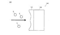
そうすると、図2Bに示すように、還元剤固形物Sにより触媒141が削り落とされ、選択還元型触媒140における触媒141の量が減少するので、排気浄化装置100における排気ガスの浄化効率が低下する。また、基体142の材質によっては、還元剤固形物Sにより、触媒141とともに基体142が削られるので、選択還元型触媒140が損傷するおそれがある。
それに対し、本実施の形態では、図3に示すように、遮断部150が、還元剤固形物Sが選択還元型触媒140への移動を遮断する。これにより、還元剤固形物Sが選択還元型触媒140に移動することがなくなるので、選択還元型触媒140の触媒141が還元剤固形物Sにより削り落とされることを抑制することができる。その結果、排気浄化装置100における排気ガスの浄化効率が低下することを抑制することができる。また、同様に、還元剤固形物Sにより選択還元型触媒140が損傷することを抑制することができる。
また、遮断部150が選択還元型触媒140に接触した構成であると、遮断部150が排気ガスの流れの抵抗となってしまい圧力損失が生じるおそれがある。より詳細には、遮断部150と基体142とが同一構造であるため、これらの排気ガスの通過孔をそろえて配置しないと、遮断部150の存在が排気ガスの流れの抵抗となってしまい、ひいては圧力損失を生じるおそれがある。また、排気浄化装置100を製造時に、排気管110に選択還元型触媒140および遮断部150を挿入する際、遮断部150により選択還元型触媒140の触媒141を剥がしたり、基体142の材質によっては、選択還元型触媒140が損傷するおそれがある。
それに対し、本実施の形態では、遮断部150が選択還元型触媒140から離間しているので、上記のような問題が発生することを抑制することができる。また、遮断部150の通過孔と基体142の通過孔とをそろえる必要がないので、排気浄化装置100を組み立てる工程を簡素化することができる。また、上記問題の発生抑制の観点から、遮断部150を選択還元型触媒140から可能な限り離間させることが好ましい。また、上記問題を解消可能である限りにおいては、遮断部150を選択還元型触媒140に接触させて配置しても良い。
また、遮断部150は、還元剤固形物Sよりも硬い材料で形成されていることが好ましい。例えば、遮断部150は、金属で構成されていることが好ましい。
遮断部150が還元剤固形物Sよりも柔らかい材料で形成されていると、還元剤固形物Sが遮断部150に接触した際に、遮断部150が削られる。そのため、徐々に遮断部150が薄くなっていき、ひいては遮断部150が完全に粉砕された状態となる可能性がある。
それに対し、遮断部150が還元剤固形物Sよりも硬い材料で形成されていると、還元剤固形物Sが遮断部150に接触しても、遮断部150が還元剤固形物Sにより粉砕されることがなくなる。その結果、遮断部150による効果を維持し続けることができる。
また、遮断部150が還元剤固形物Sによって粉砕されないので、遮断部150を比較的薄めに構成することができるので、装置全体の小型化に寄与することができる。
また、遮断部150が還元剤固形物Sよりも柔らかい材料で構成されている場合、遮断部150が完全に粉砕されにくくなる観点から、遮断部150を可能な限り厚くすることが好ましい。
また、遮断部150は、基体142と同じ材料で形成されていても良いし、異なる材料で形成されていても良い。
なお、上記実施の形態では、遮断部150が選択還元型触媒140と離間して配置されていたが、本開示はこれに限定されず、例えば、図4に示すように、遮断部が選択還元型触媒140の基体143と一体に構成されていても良い。
この構成における基体143は、排気方向における上流側の上流領域143Aと、排気方向における下流側の下流領域143Bとを有する。上流領域143Aが遮断部を構成し、触媒を担持しない非担持領域であり、下流領域143Bが触媒を担持する担持領域である。つまり、遮断部は、担持領域よりも、排気方向における上流側に位置する。
このようにしても、遮断部により、還元剤固形物が、触媒が担持される領域である担持領域に到達することを抑制することができる。
また、遮断部(上流領域143A)および担持領域(下流領域143B)が一体であるので、排気浄化装置100を組み立てる工程において、基体143を配置する工程のみで遮断部および担持領域を排気管110内に配置することができる。その結果、排気浄化装置100を組み立てる工程を簡素化することができる。
また、上記実施の形態では、遮断部150と基体142とが同一構造を有する構成であったが、本開示はこれに限定されず、同一構造を有していなくても良い。
その他、上記実施の形態は、何れも本開示を実施するにあたっての具体化の一例を示したものに過ぎず、これらによって本開示の技術的範囲が限定的に解釈されてはならないものである。すなわち、本開示はその要旨、またはその主要な特徴から逸脱することなく、様々な形で実施することができる。
本出願は、2018年11月29日付で出願された日本特許出願(特願2018-223383)に基づくものであり、その内容は、ここに参照として全て取り込まれる。
本開示の排気浄化装置は、選択還元型触媒の触媒が還元剤固形物に削り落とされることを抑制し、ひいては排気ガスの浄化効率が低下することを抑制することが可能な排気浄化装置および車両として有用である。
1 内燃機関
100 排気浄化装置
110 排気管
120 還元剤供給部
130 混合部
140 選択還元型触媒
141 触媒
142 基体
150 遮断部
V 車両
100 排気浄化装置
110 排気管
120 還元剤供給部
130 混合部
140 選択還元型触媒
141 触媒
142 基体
150 遮断部
V 車両
Claims (7)
- 内燃機関で発生した排気ガスが流れる排気管と、
前記排気管に設けられ、前記排気ガス中の窒素酸化物の還元を促進する選択還元型触媒と、
前記排気管における前記選択還元型触媒の前段に設けられ、前記排気ガス中の前記窒素酸化物を還元する還元剤を供給する還元剤供給部と、
前記排気管における前記還元剤供給部と前記選択還元型触媒との間に設けられ、還元剤固形物が前記排気ガスとともに前記排気管内を流れた場合に前記還元剤固形物の前記選択還元型触媒への移動を遮断する遮断部と、
を備える排気浄化装置。 - 前記遮断部は、前記選択還元型触媒と離間している、
請求項1に記載の排気浄化装置。 - 前記選択還元型触媒は、前記排気ガスの通過孔が形成された構造を有する基体と、前記基体に担持された触媒とを有し、
前記遮断部は、前記基体の前記構造と同一構造を有する、
請求項2に記載の排気浄化装置。 - 前記選択還元型触媒は、触媒を担持する担持領域と、前記担持領域よりも前記排気ガスにおける上流側に位置し、前記触媒を担持しない非担持領域とを含む基体を有し、
前記遮断部は、前記基体における前記非担持領域である、
請求項1に記載の排気浄化装置。 - 前記遮断部は、前記還元剤固形物よりも硬い材料で形成されている、
請求項1に記載の排気浄化装置。 - 前記遮断部は、金属で構成されている、
請求項5に記載の排気浄化装置。 - 請求項1に記載の排気浄化装置を備える、
車両。
Priority Applications (3)
| Application Number | Priority Date | Filing Date | Title |
|---|---|---|---|
| DE112019005972.6T DE112019005972T5 (de) | 2018-11-29 | 2019-11-25 | Abgasreinigungsvorrichtung und fahrzeug |
| US17/298,049 US20220097002A1 (en) | 2018-11-29 | 2019-11-25 | Exhaust purification device and vehicle |
| CN201980078108.3A CN113164868B (zh) | 2018-11-29 | 2019-11-25 | 排气净化装置以及车辆 |
Applications Claiming Priority (2)
| Application Number | Priority Date | Filing Date | Title |
|---|---|---|---|
| JP2018223383A JP2020084930A (ja) | 2018-11-29 | 2018-11-29 | 排気浄化装置および車両 |
| JP2018-223383 | 2018-11-29 |
Publications (1)
| Publication Number | Publication Date |
|---|---|
| WO2020110979A1 true WO2020110979A1 (ja) | 2020-06-04 |
Family
ID=70853390
Family Applications (1)
| Application Number | Title | Priority Date | Filing Date |
|---|---|---|---|
| PCT/JP2019/045925 Ceased WO2020110979A1 (ja) | 2018-11-29 | 2019-11-25 | 排気浄化装置および車両 |
Country Status (5)
| Country | Link |
|---|---|
| US (1) | US20220097002A1 (ja) |
| JP (1) | JP2020084930A (ja) |
| CN (1) | CN113164868B (ja) |
| DE (1) | DE112019005972T5 (ja) |
| WO (1) | WO2020110979A1 (ja) |
Citations (4)
| Publication number | Priority date | Publication date | Assignee | Title |
|---|---|---|---|---|
| JP2008128045A (ja) * | 2006-11-17 | 2008-06-05 | Mitsubishi Motors Corp | 排気浄化装置 |
| JP2008272737A (ja) * | 2007-03-30 | 2008-11-13 | Ibiden Co Ltd | ハニカムフィルタ |
| JP2013122209A (ja) * | 2011-12-12 | 2013-06-20 | Isuzu Motors Ltd | 内燃機関とその制御方法 |
| WO2017169521A1 (ja) * | 2016-03-30 | 2017-10-05 | イビデン株式会社 | 拡散部材、排ガス浄化装置及び排ガス浄化装置における拡散部材の使用 |
Family Cites Families (16)
| Publication number | Priority date | Publication date | Assignee | Title |
|---|---|---|---|---|
| GB9919013D0 (en) * | 1999-08-13 | 1999-10-13 | Johnson Matthey Plc | Reactor |
| JP2007182812A (ja) * | 2006-01-06 | 2007-07-19 | Mitsui Eng & Shipbuild Co Ltd | 排ガスの脱硝方法 |
| US20080053071A1 (en) * | 2006-09-05 | 2008-03-06 | Karen Adams | System and Method for Reducing NOx Emissions |
| JP4893454B2 (ja) * | 2007-04-27 | 2012-03-07 | トヨタ自動車株式会社 | 分散板 |
| US20090035194A1 (en) * | 2007-07-31 | 2009-02-05 | Caterpillar Inc. | Exhaust treatment system with an oxidation device for NO2 control |
| US8783022B2 (en) * | 2009-08-17 | 2014-07-22 | Donaldson Company, Inc. | Retrofit aftertreatment system for treating diesel exhaust |
| JP5602492B2 (ja) * | 2010-05-17 | 2014-10-08 | いすゞ自動車株式会社 | 排気管 |
| US9528413B2 (en) * | 2010-07-30 | 2016-12-27 | Ford Global Technologies, Llc | Synergistic SCR/DOC configurations for lowering diesel emissions |
| US8591820B2 (en) * | 2011-03-11 | 2013-11-26 | Corning Incorporated | Honeycomb filters for reducing NOx and particulate matter in diesel engine exhaust |
| JP5664771B2 (ja) * | 2011-04-28 | 2015-02-04 | トヨタ自動車株式会社 | 内燃機関の排気浄化装置 |
| BR112014021452B1 (pt) * | 2012-03-02 | 2021-01-19 | Continental Automotive Gmbh | método para operar um dispositivo de tratamento de gás de descarga e veículo motorizado |
| US9188071B2 (en) * | 2012-05-15 | 2015-11-17 | GM Global Technology Operations LLC | System and method for controlling an engine based on ammonia storage in multiple selective catalytic reduction catalysts |
| US9109495B2 (en) * | 2013-08-08 | 2015-08-18 | GM Global Technology Operations LLC | Method and system for identifying a source of nitrogen oxide reduction inefficiency |
| JP6551030B2 (ja) * | 2015-08-06 | 2019-07-31 | 三菱自動車工業株式会社 | 内燃機関の排気浄化装置 |
| WO2018054929A1 (en) * | 2016-09-20 | 2018-03-29 | Umicore Ag & Co. Kg | Diesel particle filter |
| EP3665370A1 (en) * | 2017-08-10 | 2020-06-17 | Corning Incorporated | Scr catalytic coating on particulate filters |
-
2018
- 2018-11-29 JP JP2018223383A patent/JP2020084930A/ja active Pending
-
2019
- 2019-11-25 WO PCT/JP2019/045925 patent/WO2020110979A1/ja not_active Ceased
- 2019-11-25 US US17/298,049 patent/US20220097002A1/en not_active Abandoned
- 2019-11-25 DE DE112019005972.6T patent/DE112019005972T5/de active Pending
- 2019-11-25 CN CN201980078108.3A patent/CN113164868B/zh active Active
Patent Citations (4)
| Publication number | Priority date | Publication date | Assignee | Title |
|---|---|---|---|---|
| JP2008128045A (ja) * | 2006-11-17 | 2008-06-05 | Mitsubishi Motors Corp | 排気浄化装置 |
| JP2008272737A (ja) * | 2007-03-30 | 2008-11-13 | Ibiden Co Ltd | ハニカムフィルタ |
| JP2013122209A (ja) * | 2011-12-12 | 2013-06-20 | Isuzu Motors Ltd | 内燃機関とその制御方法 |
| WO2017169521A1 (ja) * | 2016-03-30 | 2017-10-05 | イビデン株式会社 | 拡散部材、排ガス浄化装置及び排ガス浄化装置における拡散部材の使用 |
Also Published As
| Publication number | Publication date |
|---|---|
| CN113164868A (zh) | 2021-07-23 |
| CN113164868B (zh) | 2023-04-18 |
| US20220097002A1 (en) | 2022-03-31 |
| JP2020084930A (ja) | 2020-06-04 |
| DE112019005972T5 (de) | 2021-08-19 |
Similar Documents
| Publication | Publication Date | Title |
|---|---|---|
| US8747761B2 (en) | Exhaust gas purification device | |
| US9732652B2 (en) | Exhaust-gas purification device | |
| JP2009144614A (ja) | ディーゼルエンジン用の排ガス浄化装置 | |
| US20180274419A1 (en) | Exhaust gas purification apparatus for an internal combustion engine | |
| KR20160109977A (ko) | Scr 시스템 및 그 제어 방법 | |
| JP2017198097A (ja) | 内燃機関の排気ガス浄化装置 | |
| EP2535538B1 (en) | Exhaust gas purification system for internal combustion engine | |
| JP2005105970A (ja) | エンジンの排気浄化装置 | |
| JP2005090424A (ja) | エンジンの排気浄化装置 | |
| KR20150007764A (ko) | 선박용 배기가스 처리장치 및 배기가스 유해물질 동시 저감 시스템 | |
| EP2653685B1 (en) | Exhaust Gas Control Apparatus for Internal Combustion Engine and Injection Valve Holder | |
| JP2020084930A (ja) | 排気浄化装置および車両 | |
| EP2573349B1 (en) | Exhaust pipe | |
| JP2014227978A (ja) | 内燃機関の排気浄化装置 | |
| KR101892327B1 (ko) | 내연 엔진 및 내연 엔진 배열체를 작동하는 방법 | |
| JP2009144637A (ja) | 内燃機関のブローバイガス処理装置 | |
| JP2015148224A (ja) | 内燃機関の排気浄化装置 | |
| KR101497470B1 (ko) | 선박용 배기가스 처리장치 및 배기가스 유해물질 동시 저감 시스템 | |
| WO2019194881A8 (en) | Metal foil catalyst for the control of emissions from diesel engines | |
| JP2014062501A (ja) | 排気ガス浄化装置 | |
| JP6743285B2 (ja) | 還元剤供給ユニットコンパクト側方供給入口ポート | |
| JP2008128111A (ja) | 排気浄化装置の添加剤蒸発促進構造 | |
| JP2005105969A (ja) | エンジンの排気浄化装置 | |
| JP7314840B2 (ja) | 排気構造 | |
| KR20170053923A (ko) | Scr 시스템의 암모니아 슬립 억제 장치 |
Legal Events
| Date | Code | Title | Description |
|---|---|---|---|
| 121 | Ep: the epo has been informed by wipo that ep was designated in this application |
Ref document number: 19890345 Country of ref document: EP Kind code of ref document: A1 |
|
| 122 | Ep: pct application non-entry in european phase |
Ref document number: 19890345 Country of ref document: EP Kind code of ref document: A1 |