WO2020110885A1 - ソレノイド - Google Patents
ソレノイド Download PDFInfo
- Publication number
- WO2020110885A1 WO2020110885A1 PCT/JP2019/045573 JP2019045573W WO2020110885A1 WO 2020110885 A1 WO2020110885 A1 WO 2020110885A1 JP 2019045573 W JP2019045573 W JP 2019045573W WO 2020110885 A1 WO2020110885 A1 WO 2020110885A1
- Authority
- WO
- WIPO (PCT)
- Prior art keywords
- core
- solenoid
- magnetic flux
- plunger
- magnetic
- Prior art date
- Legal status (The legal status is an assumption and is not a legal conclusion. Google has not performed a legal analysis and makes no representation as to the accuracy of the status listed.)
- Ceased
Links
Images





Classifications
-
- H—ELECTRICITY
- H01—ELECTRIC ELEMENTS
- H01F—MAGNETS; INDUCTANCES; TRANSFORMERS; SELECTION OF MATERIALS FOR THEIR MAGNETIC PROPERTIES
- H01F7/00—Magnets
- H01F7/06—Electromagnets; Actuators including electromagnets
- H01F7/08—Electromagnets; Actuators including electromagnets with armatures
- H01F7/16—Rectilinearly-movable armatures
-
- H—ELECTRICITY
- H01—ELECTRIC ELEMENTS
- H01F—MAGNETS; INDUCTANCES; TRANSFORMERS; SELECTION OF MATERIALS FOR THEIR MAGNETIC PROPERTIES
- H01F7/00—Magnets
- H01F7/06—Electromagnets; Actuators including electromagnets
- H01F7/08—Electromagnets; Actuators including electromagnets with armatures
- H01F7/16—Rectilinearly-movable armatures
- H01F7/1607—Armatures entering the winding
-
- F—MECHANICAL ENGINEERING; LIGHTING; HEATING; WEAPONS; BLASTING
- F16—ENGINEERING ELEMENTS AND UNITS; GENERAL MEASURES FOR PRODUCING AND MAINTAINING EFFECTIVE FUNCTIONING OF MACHINES OR INSTALLATIONS; THERMAL INSULATION IN GENERAL
- F16K—VALVES; TAPS; COCKS; ACTUATING-FLOATS; DEVICES FOR VENTING OR AERATING
- F16K31/00—Actuating devices; Operating means; Releasing devices
- F16K31/02—Actuating devices; Operating means; Releasing devices electric; magnetic
- F16K31/06—Actuating devices; Operating means; Releasing devices electric; magnetic using a magnet, e.g. diaphragm valves, cutting off by means of a liquid
-
- F—MECHANICAL ENGINEERING; LIGHTING; HEATING; WEAPONS; BLASTING
- F16—ENGINEERING ELEMENTS AND UNITS; GENERAL MEASURES FOR PRODUCING AND MAINTAINING EFFECTIVE FUNCTIONING OF MACHINES OR INSTALLATIONS; THERMAL INSULATION IN GENERAL
- F16K—VALVES; TAPS; COCKS; ACTUATING-FLOATS; DEVICES FOR VENTING OR AERATING
- F16K31/00—Actuating devices; Operating means; Releasing devices
- F16K31/02—Actuating devices; Operating means; Releasing devices electric; magnetic
- F16K31/06—Actuating devices; Operating means; Releasing devices electric; magnetic using a magnet, e.g. diaphragm valves, cutting off by means of a liquid
- F16K31/0603—Multiple-way valves
- F16K31/061—Sliding valves
- F16K31/0613—Sliding valves with cylindrical slides
-
- F—MECHANICAL ENGINEERING; LIGHTING; HEATING; WEAPONS; BLASTING
- F16—ENGINEERING ELEMENTS AND UNITS; GENERAL MEASURES FOR PRODUCING AND MAINTAINING EFFECTIVE FUNCTIONING OF MACHINES OR INSTALLATIONS; THERMAL INSULATION IN GENERAL
- F16K—VALVES; TAPS; COCKS; ACTUATING-FLOATS; DEVICES FOR VENTING OR AERATING
- F16K31/00—Actuating devices; Operating means; Releasing devices
- F16K31/02—Actuating devices; Operating means; Releasing devices electric; magnetic
- F16K31/06—Actuating devices; Operating means; Releasing devices electric; magnetic using a magnet, e.g. diaphragm valves, cutting off by means of a liquid
- F16K31/0675—Electromagnet aspects, e.g. electric supply therefor
-
- H—ELECTRICITY
- H01—ELECTRIC ELEMENTS
- H01F—MAGNETS; INDUCTANCES; TRANSFORMERS; SELECTION OF MATERIALS FOR THEIR MAGNETIC PROPERTIES
- H01F7/00—Magnets
- H01F7/06—Electromagnets; Actuators including electromagnets
- H01F7/08—Electromagnets; Actuators including electromagnets with armatures
- H01F7/081—Magnetic constructions
-
- H—ELECTRICITY
- H01—ELECTRIC ELEMENTS
- H01F—MAGNETS; INDUCTANCES; TRANSFORMERS; SELECTION OF MATERIALS FOR THEIR MAGNETIC PROPERTIES
- H01F7/00—Magnets
- H01F7/06—Electromagnets; Actuators including electromagnets
- H01F7/08—Electromagnets; Actuators including electromagnets with armatures
- H01F7/126—Supporting or mounting
-
- H—ELECTRICITY
- H01—ELECTRIC ELEMENTS
- H01F—MAGNETS; INDUCTANCES; TRANSFORMERS; SELECTION OF MATERIALS FOR THEIR MAGNETIC PROPERTIES
- H01F7/00—Magnets
- H01F7/06—Electromagnets; Actuators including electromagnets
- H01F7/08—Electromagnets; Actuators including electromagnets with armatures
- H01F7/127—Assembling
-
- H—ELECTRICITY
- H01—ELECTRIC ELEMENTS
- H01F—MAGNETS; INDUCTANCES; TRANSFORMERS; SELECTION OF MATERIALS FOR THEIR MAGNETIC PROPERTIES
- H01F7/00—Magnets
- H01F7/06—Electromagnets; Actuators including electromagnets
- H01F7/08—Electromagnets; Actuators including electromagnets with armatures
- H01F7/081—Magnetic constructions
- H01F2007/085—Yoke or polar piece between coil bobbin and armature having a gap, e.g. filled with nonmagnetic material
Definitions
- the present disclosure relates to solenoids.
- a solenoid in which a plunger slides on the inner circumference of a stator core inside a coil that generates a magnetic force when energized.
- a magnetic ring core is arranged on the outer periphery of the stator core. This magnetically couples the magnetic circuit component such as the yoke and the stator core via the ring core, and suppresses the decrease in magnetic force due to the assembling gap between the magnetic circuit component and the stator core.
- a solenoid includes a coil that generates a magnetic force when energized, a columnar plunger that is arranged inside the coil and slides in the axial direction, a side surface portion along the axial direction, and a direction that intersects the axial direction.
- a yoke that is formed and that faces the base end face of the plunger and that houses the coil and the plunger; and a stator core that is arranged to face the tip end face of the plunger in the axial direction.
- a magnetic attraction core that magnetically attracts the plunger by the magnetic force generated by the coil, a cylindrical core portion that is arranged radially outside of the plunger, and a diameter of an end portion of the core portion that faces the bottom portion.
- a sliding core having a first magnetic flux transfer portion that is fixed to the outside in the direction and transfers the magnetic flux between the yoke and the plunger via the core portion, the sliding core, and the magnetic attraction core. Disposed between the stator core having a magnetic flux passage suppressing portion for suppressing passage of magnetic flux between the magnetic attraction core and the axial end portion of the magnetic attraction core, the end portion being opposite to the plunger side in the radial direction.
- a second magnetic flux transfer portion that transfers magnetic flux between the magnetic attraction core and the side surface portion, and an end surface of the magnetic attraction core in the axial direction that is opposite to the plunger side.
- An elastic member disposed in contact with each other and biasing the stator core toward the bottom side.
- the sliding core is fixed to the cylindrical core portion arranged radially outside the plunger and the core portion fixed radially outside the end portion of the core portion facing the bottom portion. Since there is a first magnetic flux transfer section for transferring the magnetic flux between the yoke and the plunger via, there is no radial gap between the core section and the first magnetic flux transfer section. Therefore, it is possible to prevent radial distribution from being generated in the distribution of the magnetic flux transmitted from the first magnetic flux transfer portion to the plunger through the core portion, and to suppress generation of side force due to the uneven distribution of the magnetic flux. Therefore, deterioration of the slidability of the plunger can be suppressed.
- the magnetic attraction core is provided with an elastic member that is disposed in contact with the axial end surface on the side opposite to the plunger side and biases the stator core toward the bottom side, the magnetic flux transfer section is located at the bottom.
- the magnetic flux can be pressed into contact with each other, and the loss of the magnetic flux transmitted from the bottom of the yoke to the magnetic flux transfer section can be suppressed.
- the elastic member is arranged in contact with the end surface of the magnetic attraction core, such an elastic member is provided in comparison with the structure in which the elastic member is arranged around the magnetic circuit in order to press the magnetic flux transfer portion to the bottom. It is possible to suppress a decrease in magnetic efficiency without contributing to the magnetic efficiency.
- the present disclosure can be implemented in various forms. For example, it can be realized in the form of a solenoid valve, a solenoid manufacturing method, or the like.
- FIG. 1 is a cross-sectional view showing a schematic configuration of a linear solenoid valve to which the solenoid of the first embodiment is applied
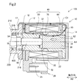
- FIG. 2 is a sectional view showing the detailed configuration of the solenoid
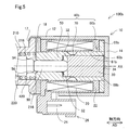
- FIG. 3 is a sectional view showing the detailed configuration of the solenoid of the second embodiment
- FIG. 4 is a cross-sectional view explaining the compression amount at the time of assembly
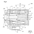
- FIG. 5 is a sectional view showing the detailed configuration of the solenoid of the third embodiment
- FIG. 6 is a cross-sectional view showing the detailed configuration of the solenoid of the fourth embodiment
- FIG. 1 is a cross-sectional view showing a schematic configuration of a linear solenoid valve to which the solenoid of the first embodiment is applied
- FIG. 2 is a sectional view showing the detailed configuration of the solenoid
- FIG. 3 is a sectional view showing the detailed configuration of the solenoid of the second embodiment
- FIG. 4 is a cross-sectional view explaining the compression amount at the time
- FIG. 7 is a cross-sectional view showing the detailed configuration of the solenoid of the fifth embodiment
- FIG. 8 is a sectional view showing the detailed configuration of the solenoid of the sixth embodiment
- FIG. 9 is a sectional view showing the detailed configuration of the solenoid of the seventh embodiment.
- the solenoid 100 of the first embodiment shown in FIG. 1 is applied to the linear solenoid valve 300 and functions as an actuator that drives the spool valve 200.
- the linear solenoid valve 300 is used to control the hydraulic pressure of hydraulic fluid supplied to an automatic transmission for a vehicle (not shown), and is arranged in a hydraulic circuit (not shown).
- the linear solenoid valve 300 includes a spool valve 200 and a solenoid 100 that are arranged side by side along the central axis AX. 1 and 2, the solenoid 100 and the linear solenoid valve 300 in the non-energized state are shown.
- the linear solenoid valve 300 of the present embodiment is a normally closed type, it may be a normally open type.
- the spool valve 200 shown in FIG. 1 adjusts the communication state and the opening area of a plurality of oil ports 214 described later.
- the spool valve 200 includes a sleeve 210, a spool 220, a spring 230, and an adjusting screw 240.
- the sleeve 210 has a substantially cylindrical appearance.
- the sleeve 210 has an insertion hole 212 penetrating along the central axis AX and a plurality of oil ports 214 communicating with the insertion hole 212 and opening in the radial direction.
- the spool 220 is inserted into the insertion hole 212.
- An end portion of the insertion hole 212 on the solenoid 100 side is formed to have an enlarged diameter and functions as an elastic member housing portion 218.
- An elastic member 420 which will be described later, is accommodated in the elastic member accommodating portion 218.
- the elastic member housing portion 218 communicates with the outside through a breathing hole (not shown) formed in the sleeve 210.
- the plurality of oil ports 214 are formed side by side along a direction parallel to the central axis AX (hereinafter, also referred to as “axial direction AD”).
- the plurality of oil ports 214 are, for example, an input port that communicates with an oil pump (not shown) to receive hydraulic pressure, an output port that communicates with a clutch piston (not shown) to supply hydraulic pressure, and a drain port that discharges hydraulic oil.
- a flange 216 is formed at the end of the sleeve 210 on the solenoid 100 side.
- the flange portion 216 has a diameter that increases outward in the radial direction and is fixed to the yoke 10 of the solenoid 100, which will be described later.
- the spool 220 has a substantially rod-shaped external shape in which a plurality of large diameter portions 222 and small diameter portions 224 are arranged side by side along the axial direction AD.
- the spool 220 slides in the insertion hole 212 along the axial direction AD, and depending on the positions of the large diameter portion 222 and the small diameter portion 224 along the axial direction AD, the communication state of the plurality of oil ports 214 and Adjust the opening area.
- a shaft 90 for transmitting the thrust of the solenoid 100 to the spool 220 is arranged in contact with one end of the spool 220.
- a spring 230 is arranged at the other end of the spool 220.
- the spring 230 is composed of a compression coil spring, presses the spool 220 in the axial direction AD, and urges it toward the solenoid 100.
- the adjusting screw 240 is arranged in contact with the spring 230 and adjusts the spring load of the spring 230 by adjusting the screwing amount with respect to the sleeve 210.
- the solenoid 100 shown in FIGS. 1 and 2 is energized by an electronic control unit (not shown) to drive the spool valve 200.
- the solenoid 100 includes a yoke 10, a ring member 18, a coil 20, a plunger 30, a stator core 40, and an elastic member 420.
- the yoke 10 is formed of a magnetic metal and constitutes the outer shell of the solenoid 100.
- the yoke 10 has a bottomed tubular external shape and accommodates the coil 20, the plunger 30, and the stator core 40.
- the yoke 10 has a side surface portion 12, a bottom portion 14, and an opening portion 17.
- the side surface portion 12 has a substantially cylindrical external shape along the axial direction AD.
- An end portion of the side surface portion 12 on the spool valve 200 side is formed thin to form a thin portion 15.
- the bottom portion 14 is continuous with the end portion of the side surface portion 12 on the side opposite to the spool valve 200 side and is formed perpendicularly to the axial direction AD, and closes the end portion of the side surface portion 12.
- the bottom portion 14 is not limited to being perpendicular to the axial direction AD and may be formed substantially perpendicularly, or may be formed to intersect the axial direction AD at any angle other than 90°.
- the bottom portion 14 faces a base end surface 34 of the plunger 30 described later.
- the opening 17 is formed in the thin portion 15 at the end of the side surface portion 12 on the spool valve 200 side. After the components of the solenoid 100 are assembled inside the yoke 10, the opening 17 is caulked and fixed to the collar 216 of the spool valve 200. Instead of caulking and fixing, the spool valve 200 and the yoke 10 may be fixed by using an arbitrary method such as welding.
- the ring member 18 is arranged between the coil 20 and the collar portion 216 of the spool valve 200 in the axial direction AD.
- the ring member 18 has a diameter of an end portion (hereinafter, also referred to as “end portion 54 ”) of the magnetic attraction core 50 of the stator core 40, which will be described later, in the axial direction AD and opposite to the plunger 30 side. It is located outside in the direction.
- the ring member 18 has a ring-shaped appearance and is made of a magnetic metal.
- the ring member 18 transfers the magnetic flux between the magnetic attraction core 50 of the stator core 40 and the side surface portion 12 of the yoke 10.
- the ring member 18 is configured to be displaceable in the radial direction.
- the magnetic attraction core 50 described later is press-fitted into the ring member 18.
- the magnetic attraction core 50 is not limited to press-fitting, and may be fitted with a slight radial gap.
- the coil 20 is composed of a resin bobbin 22 arranged inside the side surface portion 12 of the yoke 10 and a conductive wire having an insulating coating wound around the bobbin 22. The ends of the conductive wires forming the coil 20 are connected to the connection terminals 24.
- the connection terminal 24 is arranged inside the connector 26.
- the connector 26 is arranged on the outer peripheral portion of the yoke 10 and electrically connects the solenoid 100 and the electronic control unit via a connection line (not shown).
- the coil 20 generates a magnetic force when energized, and the loop-shaped magnetic flux flows through the side surface portion 12 of the yoke 10, the bottom portion 14 of the yoke 10, the stator core 40, the plunger 30, and the ring member 18 ( Hereinafter, also referred to as a "magnetic circuit").
- the coil 20 is not energized and the magnetic circuit is not formed, but for convenience of description, the magnetic circuit C1 formed when the coil 20 is energized. Is schematically indicated by a thick arrow in FIG.
- the plunger 30 has a substantially columnar outer shape and is made of a magnetic metal.
- the plunger 30 slides in the axial direction AD on the inner peripheral surface of the core portion 61 of the stator core 40 described later.
- the shaft 90 described above is disposed in contact with the end surface of the plunger 30 on the spool valve 200 side (hereinafter, also referred to as the “tip surface 32”).
- the plunger 30 is biased toward the bottom portion 14 side of the yoke 10 along the axial direction AD by the biasing force of the spring 230 transmitted to the spool 220.
- An end surface on the side opposite to the tip surface 32 (hereinafter, also referred to as “base end surface 34”) faces the bottom portion 14 of the yoke 10.
- the plunger 30 is provided with a breathing hole (not shown) which penetrates in the axial direction AD.
- the breathing holes allow fluids, such as hydraulic oil and air, located on the proximal end surface 34 side and the distal end surface 32 side of the plunger 30 to pass therethrough.
- the stator core 40 is made of magnetic metal and is arranged between the coil 20 and the plunger 30.
- the stator core 40 has a magnetic attraction core 50, a sliding core 60, and a magnetic flux passage suppression unit 70.
- the magnetic attraction core 50 is arranged so as to surround the shaft 90 in the circumferential direction.
- the magnetic attraction core 50 constitutes a part of the stator core 40 on the spool valve 200 side, and magnetically attracts the plunger 30 by the magnetic force generated by the coil 20.
- a stopper 52 is arranged on the surface of the magnetic attraction core 50 facing the tip surface 32 of the plunger 30.
- the stopper 52 is made of a non-magnetic material, and prevents the plunger 30 and the magnetic attraction core 50 from directly contacting each other, and prevents the plunger 30 from being separated from the magnetic attraction core 50 by magnetic attraction.
- the sliding core 60 constitutes a part of the stator core 40 on the bottom portion 14 side, and is arranged radially outside of the plunger 30.
- the sliding core 60 has a core portion 61 and a magnetic flux transfer portion 65.
- the core portion 61 has a substantially cylindrical outer shape, and is arranged between the coil 20 and the plunger 30 in the radial direction.
- the core portion 61 guides the movement of the plunger 30 along the axial direction AD.
- the plunger 30 directly slides on the inner peripheral surface of the core portion 61.
- a sliding gap (not shown) for ensuring the slidability of the plunger 30 exists between the core portion 61 and the plunger 30.
- An end portion of the sliding core 60 which is opposite to the magnetic attraction core 50 side (hereinafter, also referred to as “end portion 62 ”), faces and abuts the bottom portion 14.
- the magnetic flux transfer portion 65 is formed over the entire circumference of the end portion 62 from the end portion 62 toward the outer side in the radial direction. Therefore, the magnetic flux transfer portion 65 is located between the bobbin 22 and the bottom portion 14 of the yoke 10 in the axial direction AD.
- the magnetic flux transfer section 65 transfers the magnetic flux between the yoke 10 and the plunger 30 via the core section 61. More specifically, the magnetic flux transfer section 65 transfers magnetic flux between the bottom portion 14 of the yoke 10 and the plunger 30.
- the magnetic flux transfer section 65 may transfer the magnetic flux between the side surface portion 12 of the yoke 10 and the plunger 30. In the present embodiment, a radial gap is provided between the magnetic flux transfer portion 65 and the side surface portion 12 of the yoke 10 for assembly.
- the magnetic flux passage suppression portion 70 is formed between the magnetic attraction core 50 and the core portion 61 in the axial direction AD.
- the magnetic flux passage suppressing portion 70 suppresses the direct flow of magnetic flux between the core portion 61 and the magnetic attraction core 50.
- the magnetic flux passage suppression unit 70 of the present embodiment is configured such that the stator core 40 is formed to have a small radial thickness, and thus has a larger magnetic resistance than the magnetic attraction core 50 and the core unit 61.
- the elastic member 420 is housed in the elastic member housing portion 218 formed on the sleeve 210 of the spool valve 200, and biases the stator core 40 toward the bottom portion 14 side.
- the elastic member 420 is arranged in contact with the end surface of the magnetic attraction core 50 in the axial direction AD, which is opposite to the plunger 30 side (hereinafter, also referred to as “end surface 56 ”).
- the elastic member 420 is composed of a compression coil spring having a substantially cylindrical external shape.
- the compression coil spring is composed of a wire material having a round cross section.
- the spool 220 is inserted inside the elastic member 420 in the radial direction.
- the stator core 40 is urged in the axial direction AD toward the bottom portion 14 side of the yoke 10 by the elastic member 420, the magnetic flux transfer portion 65 is pressed against the bottom portion 14 and from the bottom portion 14 of the yoke 10 to the magnetic flux transfer portion 65. The loss of the transmitted magnetic flux is suppressed.
- the yoke 10, the ring member 18, the plunger 30, and the stator core 40 are each made of iron.
- the material is not limited to iron, and may be composed of any magnetic material such as nickel or cobalt.
- the elastic member 420 is made of austenitic stainless steel.
- the material is not limited to austenitic stainless steel, and may be formed of any non-magnetic material such as aluminum or brass.
- the material is not limited to a non-magnetic material, and may be a magnetic material.
- the yoke 10 is formed by press molding and the stator core 40 is formed by forging, but each may be formed by any molding method.
- the magnetic circuit C1 includes a side surface portion 12 of the yoke 10, a bottom portion 14 of the yoke 10, a magnetic flux transfer portion 65 of the stator core 40, a core portion 61 of the stator core 40, a plunger 30, and a stator core 40.
- the magnetic attraction core 50 and the ring member 18 are formed. Therefore, when the coil 20 is energized, the plunger 30 is pulled toward the magnetic attraction core 50 side. As a result, the plunger 30 slides on the inner peripheral surface of the core portion 61, in other words, on the inner peripheral surface of the sliding core 60, in the direction of the outlined arrow along the axial direction AD.
- the stroke amount of the plunger 30 means the position where the plunger 30 is farthest from the magnetic attraction core 50 as a base point, and the reciprocating motion of the plunger 30 causes the plunger 30 to move toward the magnetic attraction core 50 side along the axial direction AD. It means the amount to move.
- the state where the plunger 30 is farthest from the magnetic attraction core 50 corresponds to the non-energized state.
- the state where the plunger 30 is closest to the magnetic attraction core 50 corresponds to the state where the coil 20 is energized and the tip surface 32 of the plunger 30 and the stopper 52 are in contact with each other.
- the stroke amount of 30 is the maximum.
- the core portion 61 and the magnetic flux transfer portion 65 are integrally formed. Therefore, there is no radial gap between the core portion 61 and the magnetic flux transfer portion 65. Therefore, when a magnetic circuit is formed by energization, it is possible to prevent radial distribution from being generated in the distribution of the magnetic flux transmitted from the magnetic flux transfer portion 65 to the core portion 61, and from the core portion 61 to the plunger 30. It is possible to suppress the occurrence of radial deviation in the distribution of the transmitted magnetic flux. In other words, the magnetic flux density of the magnetic circuit is substantially equal in the circumferential direction. Therefore, it is possible to suppress the generation of side force due to the uneven distribution of the magnetic flux.
- the magnetic flux transfer section 65 corresponds to a subordinate concept of the first magnetic flux transfer section in the present disclosure
- the ring member 18 corresponds to a subordinate concept of the second magnetic flux transfer section in the present disclosure.
- the sliding core 60 includes the tubular core portion 61 arranged radially outside of the plunger 30 and the radial direction from the end portion 62 of the core portion 61. Since it has the magnetic flux transfer part 65 formed toward the outside to transfer the magnetic flux, there is no radial gap between the core part 61 and the magnetic flux transfer part 65. For this reason, it is possible to prevent radial distribution from being generated in the distribution of the magnetic flux transmitted from the magnetic flux transfer section 65 to the plunger 30 via the core portion 61, and to suppress generation of side force due to the uneven distribution of the magnetic flux. .. Therefore, deterioration of the slidability of the plunger 30 can be suppressed.
- stator core 40 is composed of a single member in which the magnetic attraction core 50, the sliding core 60, and the magnetic flux passage suppressing portion 70 are integrated, it is possible to suppress an increase in the number of parts.
- the elastic member 420 biases the stator core 40 toward the bottom portion 14 side of the yoke 10
- the magnetic flux passing portion 65 can be pressed against the bottom portion 14, and the bottom portion 14 of the yoke 10 moves to the magnetic flux passing portion 65.
- the loss of the magnetic flux transmitted with can be suppressed.
- the bottomed tubular yoke 10 having the bottom portion 14 connected to the side surface portion 12 is provided, the side surface portion 12 and the bottom portion 14 are separately formed, and the bottom portion 14 is caulked and fixed to the side surface portion 12.
- the yoke 10 can be easily formed by press forming, as compared with the configuration in which the bridge portion 65 and the bottom portion 14 are brought into pressure contact with each other.
- the side surface portion 12 and the bottom portion 14 are separately formed, as a method of forming the side surface portion 12, there is a method of cutting and removing a portion corresponding to the bottom portion 14 after forming the yoke 10 by press molding. As expected, the processing accuracy of the side surface portion 12 may be reduced. As another method, a method of cutting and polishing the surface of the cylindrical member by cutting to form the side surface portion 12 is assumed, but the cost required for manufacturing the side surface portion 12 may increase.
- the solenoid 100 of the present embodiment since the bottomed cylindrical yoke 10 having the bottom portion 14 connected to the side surface portion 12 is provided, the yoke 10 can be easily formed by press forming, and the number of parts can be increased. It can be suppressed and the caulking step can be omitted. Therefore, the manufacturing process of the yoke 10 can be prevented from becoming complicated, and the cost required to manufacture the solenoid 100 can be prevented from increasing.
- stator core 40 is urged toward the bottom portion 14 side of the yoke 10 by the elastic member 420, when the constituent parts of the solenoid 100 are affected by creep due to the temperature rise caused by the driving of the solenoid 100, such constituent parts are performed. Can be absorbed by the elastic force of the elastic member 420, and a decrease in the pressure contact load between the magnetic flux transfer portion 65 and the bottom portion 14 can be suppressed. Further, since the elastic member 420 is composed of the compression coil spring, it is possible to suppress an increase in cost required for manufacturing the elastic member 420.
- the elastic member 420 is formed of a non-magnetic material, it is possible to prevent foreign matter of magnetic material such as iron contained in the hydraulic oil from being attracted to and attached to the elastic member 420, and such foreign matter is accommodated in the elastic member accommodating portion. It is possible to suppress the accumulation on 218. Therefore, it is possible to prevent the slidability of the shaft 90 and the plunger 30 from being deteriorated due to the foreign matter accumulated in the elastic member housing portion 218. Further, since the elastic member 420 is made of metal, it is possible to suppress deterioration of durability. Therefore, it is possible to suppress a decrease in the biasing force of the elastic member 420 and a decrease in magnetic efficiency.
- the elastic member 420 is arranged in contact with the end surface 56 of the magnetic attraction core 50, so that the elastic member 420 is arranged closer to the spool valve 200 than the formation position of the magnetic circuit C1. Therefore, as compared with the configuration in which the elastic member is arranged around the magnetic circuit C1 in order to press the magnetic flux transfer portion 65 against the bottom portion 14, the elastic member does not contribute to the magnetic efficiency and the magnetic efficiency is reduced. Can be suppressed. Further, it is possible to expand and arrange a part of the magnetic flux transfer section 65 and increase the number of turns of the conductive wire of the coil 20, and it is possible to further suppress a decrease in magnetic efficiency of the solenoid 100.
- the solenoid 100a of the second embodiment shown in FIG. 3 differs from the solenoid 100 of the first embodiment in that an elastic member 420a is provided instead of the elastic member 420. Since other configurations are the same as those of the solenoid 100 of the first embodiment, the same components are designated by the same reference numerals, and detailed description thereof will be omitted.
- the elastic member 420a included in the solenoid 100a according to the second embodiment is configured by a so-called square spring formed of a wire having a square cross section.
- the spring constant of a square spring is higher than the spring constant of a so-called round spring formed of a wire having a round cross section. Therefore, by using the square spring, the length of the elastic member 420a along the axial direction AD for generating the load necessary for biasing the stator core 40 toward the bottom portion 14 can be shortened.
- FIG. 4 shows states of the solenoid 100 of the first embodiment and the solenoid 100a of the second embodiment before the solenoids 100, 100a and the spool valve 200 are assembled.
- the free length can be shortened as compared with the configuration using the round spring as the elastic member 420.
- CL2 can be made smaller than the compression amount CL1 when a round spring is used.
- the same effect as that of the first embodiment can be obtained.
- the elastic member 420a is configured by a so-called square spring formed of a wire having a square cross section, the spring constant can be increased. Therefore, the free length of the elastic member 420a can be shortened, the compression amount CL2 at the time of assembling can be reduced, and the assembling property can be improved.
- the solenoid 100b of the third embodiment shown in FIG. 5 is different from the solenoid 100 of the first embodiment in that a stator core 40b is provided instead of the stator core 40. Since other configurations are the same as those of the solenoid 100 of the first embodiment, the same components are designated by the same reference numerals, and detailed description thereof will be omitted.
- the core portion 61b and the magnetic flux transfer portion 65b are formed separately.
- the magnetic flux transfer section 65b has a ring-shaped appearance. Therefore, the magnetic flux transfer portion 65b is formed with a through hole 66b that penetrates in the axial direction AD on the radially inner side.
- the end portion 62b of the core portion 61b is press-fitted into the through hole 66b.
- the core portion 61b may be inserted into the through hole 66b and integrated with the magnetic flux transfer portion 65b by welding or the like without being limited to press fitting.
- the same effect as that of the first embodiment can be obtained.
- the magnetic flux transfer portion 65b is formed separately from the core portion 61b and has the through hole 66b, and the core portion 61b is inserted into the through hole 66b and integrated with the magnetic flux transfer portion 65b, the stator core 40b It is possible to prevent the structure from becoming complicated, and it is possible to suppress an increase in cost required for manufacturing the stator core 40b.
- the solenoid 100c of the fourth embodiment shown in FIG. 6 differs from the solenoid 100b of the third embodiment in the method of fixing the core portion 61c and the magnetic flux transfer portion 65b. More specifically, the solenoid 100c of the fourth embodiment includes a stator core 40c instead of the stator core 40b. Since other configurations are the same as those of the solenoid 100b of the third embodiment, the same components are designated by the same reference numerals, and detailed description thereof will be omitted.
- the core portion 61c of the sliding core 60c of the stator core 40c is formed with a protruding portion 63c protruding radially outward.
- the magnetic flux transfer portion 65b is sandwiched between the protruding portion 63c and the bottom portion 14 in the axial direction AD by the urging force of the elastic member 420, and is pressed into contact therewith. As a result, the magnetic flux transfer portion 65b is fixed to the outside in the radial direction of the end portion 62b of the core portion 61c.
- the same effect as that of the third embodiment is obtained.
- the magnetic flux transfer portion 65b is fixed to the outside in the radial direction of the end portion 62b of the core portion 61c by the protruding portion 63c formed on the core portion 61c of the stator core 40c, the core portion 61c and the magnetic flux transfer portion 65b are separated from each other.
- the press-fitting process can be omitted, and the assembly process of the solenoid 100c can be simplified.
- the solenoid 100d of the fifth embodiment shown in FIG. 7 differs from the solenoid 100c of the fourth embodiment in that the yoke 10d is provided instead of the yoke 10. Since other configurations are the same as those of the solenoid 100c of the fourth embodiment, the same components are designated by the same reference numerals, and detailed description thereof will be omitted.
- the side surface portion 12d and the bottom portion 14d are formed separately.
- the bottom portion 14d has a substantially disc-shaped outer shape, and is fixed to the side surface portion 12d by being press-fitted into the side surface portion 12d.
- the same effect as that of the fourth embodiment can be obtained.
- the bottom portion 14d is formed separately from the side surface portion 12d, for example, the bottom portion 14d can be formed of a non-magnetic material such as aluminum, and the generation of the force by which the bottom portion 14d attracts the plunger 30 can be suppressed.
- the solenoid 100e of the sixth embodiment shown in FIG. 8 is different from the solenoid 100 of the first embodiment in that a stator core 40e having a magnetic flux passage suppressing portion 70e is provided instead of the magnetic flux passage suppressing portion 70. Since other configurations are the same as those of the solenoid 100 of the first embodiment, the same components are designated by the same reference numerals, and detailed description thereof will be omitted.
- the magnetic flux passage suppressing portion 70e in the solenoid 100e of the sixth embodiment includes a connecting portion 72e made of a non-magnetic material.
- the connecting portion 72e physically connects the separately formed magnetic attraction core 50 and the sliding core 60.
- the connecting portion 72e is formed thinner than the core portion 61, and physically connects the magnetic attraction core 50 and the sliding core 60 on the inner peripheral surface side of the coil 20. Therefore, there is a gap between the inner peripheral surface of the connecting portion 72e and the outer peripheral surface of the plunger 30.
- the connecting portion 72e is formed of austenitic stainless steel, but it is not limited to austenitic stainless steel, and may be formed of any non-magnetic material such as aluminum or brass.
- the same effect as that of the first embodiment can be obtained.
- the magnetic flux passage suppressing portion 70e includes the connecting portion 72e formed of a non-magnetic material, the magnetic flux directly flows from the core portion 61 to the magnetic attraction core 50 without passing through the plunger 30 during energization. Passing can be suppressed more.
- the solenoid 100f of the seventh embodiment shown in FIG. 9 is different from the solenoid 100e of the sixth embodiment in that it has a magnetic flux passage suppressing portion 70f including the connecting portion 72f in place of the connecting portion 72e. Since other configurations are the same as those of the solenoid 100e of the eighth embodiment, the same reference numerals are given to the same configurations, and detailed description thereof will be omitted.
- the connecting portion 72f in the solenoid 100f of the seventh embodiment has a thickness substantially equal to that of the core portion 61 and is formed by brazing or the like.
- the same effect as the sixth embodiment can be obtained.
- the connecting portion 72f is formed with a thickness substantially equal to that of the core portion 61, the magnetic attraction core 50 and the core portion 61 can be connected more firmly. Further, the sliding of the plunger 30 can be guided also at the connecting portion 72f.
- the configurations of the elastic members 420 and 420a are merely examples, and various modifications can be made.
- the compression coil spring is not limited to a substantially cylindrical shape, and may be formed of a compression coil spring having an arbitrary shape such as a substantially conical shape. Good.
- the spring constant can be increased in the mode constituted by the disc spring.
- the material is not limited to metal and may be made of resin or the like. With such a configuration, the same effect as that of each of the above-described embodiments can be obtained.
- the bottom portion 14d is fixed to the side surface portion 12d by being press-fitted into the side surface portion 12d.
- the bottom portion 14d may be fixed by caulking instead of being press-fitted and fixed. That is, in general, the bottom portion may be formed separately from the side surface portion and fixed to the side surface portion by press fitting or caulking. Even with this configuration, the same effect as that of the fifth embodiment can be obtained.
- the plunger 30 is not limited to the substantially columnar shape, and may have an arbitrary columnar appearance shape.
- the side portions 12 and 12d of the core portions 61, 61b and 61c and the yokes 10 and 10d are not limited to the substantially cylindrical shape, but may be designed to have a cylindrical appearance shape according to the appearance shape of the plunger 30.
- the yokes 10 and 10d may have an arbitrary bottomed tubular external shape such as a substantially quadrangular cross-sectional view, and are not limited to the bottomed tubular shape and have a plate shape surrounding the coil 20 and the plunger 30. It may have an external shape such as. Even with such a configuration, the same effects as those of the above-described respective embodiments can be obtained.
- the solenoids 100, 100a to 100f of the above embodiments are applied to the linear solenoid valve 300 for controlling the hydraulic pressure of the hydraulic oil supplied to the vehicle automatic transmission, and function as actuators for driving the spool valve 200.
- the present disclosure is not limited to this.
- it may be applied to any solenoid valve such as an electromagnetic oil passage switching valve of a valve timing adjusting device that adjusts the valve timing of an intake valve or an exhaust valve of an engine.
- an arbitrary valve such as a poppet valve may be driven instead of the spool valve 200, and an arbitrary driven body such as a switch may be driven instead of the valve.
Landscapes
- Physics & Mathematics (AREA)
- Electromagnetism (AREA)
- Engineering & Computer Science (AREA)
- Power Engineering (AREA)
- General Engineering & Computer Science (AREA)
- Mechanical Engineering (AREA)
- Magnetically Actuated Valves (AREA)
- Electromagnets (AREA)
Abstract
ソレノイド(100,100a~100f)は、コイル(20)と、プランジャ(30)と、側面部(12,12d)と底部(14,14d)とを有するヨーク(10,10d)と、ステータコア(40,40b,40c,40e)であって、磁気吸引コア(50)と、筒状のコア部(61,61b,61c)と、前記コア部を介して前記ヨークと前記プランジャとの間における磁束の受け渡しを行なう第1磁束受渡部(65,65b)と、を有する摺動コア(60,60b,60c)と、前記摺動コアと前記磁気吸引コアとの間における磁束の通過を抑制する磁束通過抑制部(70,70e,70f)と、を有するステータコアと、前記磁気吸引コアと前記側面部との間における磁束の受け渡しを行なう第2磁束受渡部(18)と、前記磁気吸引コアの端面(56)と当接して配置され、前記ステータコアを前記底部側へと付勢する弾性部材(420,420a)とを備える。
Description
本出願は、2018年11月26日に出願された日本出願番号2018-219984号に基づくもので、ここにその記載内容を援用する。
本開示は、ソレノイドに関する。
従来から、通電により磁力を発生するコイルの内側において、ステータコアの内周をプランジャが摺動するソレノイドが知られている。特許文献1に記載のソレノイドでは、ステータコアの外周に磁性体のリングコアが配置されている。これにより、ヨーク等の磁気回路部品とステータコアとをリングコアを介して磁気結合させ、磁気回路部品とステータコアとの間の組付隙間に起因する磁力低下を抑制している。
特許文献1に記載のソレノイドでは、リングコアが径方向に移動可能に構成されているため、摺動コアに対してリングコアが偏心して組み付けられて、摺動コアとリングコアとの間の隙間の大きさに径方向の偏りが発生するおそれがある。これにより、リングコアを通って摺動コアとプランジャとに伝達される磁束の分布に径方向の偏りが発生し、径方向への吸引力がサイドフォースとして発生するおそれがある。サイドフォースが大きくなると、プランジャの摺動性が悪化するおそれがある。このため、プランジャの摺動性の悪化を抑制できる技術が望まれている。
本開示は、以下の形態として実現することが可能である。
本開示の一形態によれば、ソレノイドが提供される。このソレノイドは、通電により磁力を発生するコイルと、前記コイルの内側に配置されて軸方向に摺動する柱状のプランジャと、前記軸方向に沿った側面部と、前記軸方向と交差する方向に形成され前記プランジャの基端面と対向する底部と、を有し、前記コイルと前記プランジャとを収容するヨークと、ステータコアであって、前記軸方向において前記プランジャの先端面と対向して配置されて前記コイルが発生する磁力により前記プランジャを磁気吸引する磁気吸引コアと、前記プランジャに対して径方向外側に配置された筒状のコア部と、前記底部と対向する前記コア部の端部の径方向外側に固定されて前記コア部を介して前記ヨークと前記プランジャとの間における磁束の受け渡しを行なう第1磁束受渡部と、を有する摺動コアと、前記摺動コアと前記磁気吸引コアとの間における磁束の通過を抑制する磁束通過抑制部と、を有するステータコアと、前記磁気吸引コアにおける前記軸方向の端部であって前記プランジャ側とは反対側の端部の径方向外側に配置され、前記磁気吸引コアと前記側面部との間における磁束の受け渡しを行なう第2磁束受渡部と、前記磁気吸引コアにおける前記軸方向の端面であって前記プランジャ側とは反対側の端面と当接して配置され、前記ステータコアを前記底部側へと付勢する弾性部材と、を備える。
この形態のソレノイドによれば、摺動コアが、プランジャに対して径方向外側に配置された筒状のコア部と、底部と対向するコア部の端部の径方向外側に固定されてコア部を介してヨークとプランジャとの間における磁束の受け渡しを行なう第1磁束受渡部とを有するので、コア部と第1磁束受渡部との間に径方向の隙間が存在しない。このため、コア部を介して第1磁束受渡部からプランジャへと伝達される磁束の分布に径方向の偏りが発生することを抑制でき、磁束の分布の偏りによるサイドフォースの発生を抑制できる。したがって、プランジャの摺動性の悪化を抑制できる。加えて、磁気吸引コアにおける軸方向の端面であってプランジャ側とは反対側の端面と当接して配置され、ステータコアを底部側へと付勢する弾性部材を備えるので、磁束受渡部を底部に圧接させることができ、ヨークの底部から磁束受渡部へと伝達される磁束の損失を抑制できる。また、弾性部材が、磁気吸引コアの端面と当接して配置されるので、磁束受渡部を底部に圧接させるために磁気回路の周辺に弾性部材を配置する構成と比較して、かかる弾性部材が磁気効率に寄与せずに磁気効率が低下することを抑制できる。
本開示は、種々の形態で実現することも可能である。例えば、ソレノイドバルブ、ソレノイドの製造方法等の形態で実現することができる。
本開示についての上記目的およびその他の目的、特徴や利点は、添付の図面を参照しながら下記の詳細な記述により、より明確になる。その図面は、
図1は、第1実施形態のソレノイドが適用されたリニアソレノイドバルブの概略構成を示す断面図であり、
図2は、ソレノイドの詳細構成を示す断面図であり、
図3は、第2実施形態のソレノイドの詳細構成を示す断面図であり、
図4は、組み付けの際の圧縮量について説明する断面図であり、
図5は、第3実施形態のソレノイドの詳細構成を示す断面図であり、
図6は、第4実施形態のソレノイドの詳細構成を示す断面図であり、
図7は、第5実施形態のソレノイドの詳細構成を示す断面図であり、
図8は、第6実施形態のソレノイドの詳細構成を示す断面図であり、
図9は、第7実施形態のソレノイドの詳細構成を示す断面図である。
A.第1実施形態
A-1.構成
図1に示す第1実施形態のソレノイド100は、リニアソレノイドバルブ300に適用され、スプール弁200を駆動させるアクチュエータとして機能する。リニアソレノイドバルブ300は、図示しない車両用自動変速機に供給する作動油の油圧を制御するために用いられ、図示しない油圧回路に配置されている。リニアソレノイドバルブ300は、中心軸AXに沿って互いに並んで配置された、スプール弁200と、ソレノイド100とを備える。なお、図1および図2では、非通電状態のソレノイド100およびリニアソレノイドバルブ300を示している。本実施形態のリニアソレノイドバルブ300は、ノーマリクローズタイプであるが、ノーマリオープンタイプであってもよい。
A-1.構成
図1に示す第1実施形態のソレノイド100は、リニアソレノイドバルブ300に適用され、スプール弁200を駆動させるアクチュエータとして機能する。リニアソレノイドバルブ300は、図示しない車両用自動変速機に供給する作動油の油圧を制御するために用いられ、図示しない油圧回路に配置されている。リニアソレノイドバルブ300は、中心軸AXに沿って互いに並んで配置された、スプール弁200と、ソレノイド100とを備える。なお、図1および図2では、非通電状態のソレノイド100およびリニアソレノイドバルブ300を示している。本実施形態のリニアソレノイドバルブ300は、ノーマリクローズタイプであるが、ノーマリオープンタイプであってもよい。
図1に示すスプール弁200は、後述する複数のオイルポート214の連通状態および開口面積を調整する。スプール弁200は、スリーブ210と、スプール220と、バネ230と、アジャストスクリュ240とを備える。
スリーブ210は、略円筒状の外観形状を有する。スリーブ210には、中心軸AXに沿って貫通する挿入孔212と、挿入孔212と連通して径方向に開口する複数のオイルポート214とが形成されている。挿入孔212には、スプール220が挿入されている。挿入孔212のソレノイド100側の端部は、拡径して形成され、弾性部材収容部218として機能する。弾性部材収容部218には、後述する弾性部材420が収容される。弾性部材収容部218は、スリーブ210に形成された図示しない呼吸孔を介して外部と連通している。複数のオイルポート214は、中心軸AXと平行な方向(以下、「軸方向AD」とも呼ぶ)に沿って互いに並んで形成されている。複数のオイルポート214は、例えば、図示しないオイルポンプと連通して油圧の供給を受ける入力ポート、図示しないクラッチピストン等と連通して油圧を供給する出力ポート、作動油を排出するドレインポート等として機能する。スリーブ210のソレノイド100側の端部には、鍔部216が形成されている。鍔部216は、径方向外側に向かって拡径しており、後述するソレノイド100のヨーク10と互いに固定される。
スプール220は、軸方向ADに沿って複数の大径部222と小径部224とが並んで配置された略棒状の外観形状を有する。スプール220は、挿入孔212の内部において軸方向ADに沿って摺動し、大径部222と小径部224との軸方向ADに沿った位置に応じて、複数のオイルポート214の連通状態および開口面積を調整する。スプール220の一端には、ソレノイド100の推力をスプール220に伝達するための、シャフト90が当接して配置されている。スプール220の他端には、バネ230が配置されている。バネ230は、圧縮コイルスプリングにより構成され、スプール220を軸方向ADに押圧してソレノイド100側へと付勢する。アジャストスクリュ240は、バネ230と当接して配置され、スリーブ210に対するねじ込み量が調整されることにより、バネ230のバネ荷重を調整する。
図1および図2に示すソレノイド100は、図示しない電子制御装置によって通電制御されて、スプール弁200を駆動する。ソレノイド100は、ヨーク10と、リング部材18と、コイル20と、プランジャ30と、ステータコア40と、弾性部材420とを備える。
図2に示すように、ヨーク10は、磁性体の金属により形成され、ソレノイド100の外郭を構成している。ヨーク10は、有底筒状の外観形状を有し、コイル20とプランジャ30とステータコア40とを収容する。ヨーク10は、側面部12と、底部14と、開口部17とを有する。
側面部12は、軸方向ADに沿った略円筒状の外観形状を有する。側面部12のスプール弁200側の端部は、薄肉に形成され、薄肉部15を構成している。底部14は、側面部12のスプール弁200側とは反対側の端部に連なって軸方向ADと垂直に形成され、側面部12の端部を閉塞している。なお、底部14は、軸方向ADと垂直に限らず、略垂直に形成されてもよく、90°以外の任意の角度で軸方向ADと交差して形成されてもよい。底部14は、後述するプランジャ30の基端面34と対向している。開口部17は、側面部12のスプール弁200側の端部の薄肉部15に形成されている。開口部17は、ヨーク10の内部にソレノイド100の構成部品が組み付けられた後、スプール弁200の鍔部216とかしめ固定される。なお、かしめ固定に代えて、溶接等の任意の方法を用いてスプール弁200とヨーク10とが固定されてもよい。
リング部材18は、軸方向ADにおいてコイル20とスプール弁200の鍔部216との間に配置されている。換言すると、リング部材18は、後述するステータコア40の磁気吸引コア50における軸方向ADの端部であってプランジャ30側とは反対側の端部(以下、「端部54」とも呼ぶ)の径方向外側に配置されている。リング部材18は、リング状の外観形状を有し、磁性体の金属により構成されている。リング部材18は、ステータコア40の磁気吸引コア50とヨーク10の側面部12との間における磁束の受け渡しを行なう。リング部材18は、径方向において変位可能に構成されている。これにより、ステータコア40の製造上の寸法ばらつきと組み付け上の軸ずれとが吸収される。本実施形態において、リング部材18には、後述する磁気吸引コア50が圧入されている。なお、圧入に限らず、径方向の僅かな隙間を設けて磁気吸引コア50が嵌合されていてもよい。
コイル20は、ヨーク10の側面部12の内側に配置された樹脂製のボビン22に、絶縁被覆が施された導線が巻回されて構成されている。コイル20を構成する導線の端部は、接続端子24に接続されている。接続端子24は、コネクタ26の内部に配置されている。コネクタ26は、ヨーク10の外周部に配置され、図示しない接続線を介してソレノイド100と電子制御装置との電気的な接続を行なう。コイル20は、通電されることにより磁力を発生し、ヨーク10の側面部12と、ヨーク10の底部14と、ステータコア40と、プランジャ30と、リング部材18とを通るループ状の磁束の流れ(以下、「磁気回路」とも呼ぶ)を形成させる。図1および図2に示す状態では、コイル20への通電が実行されず、磁気回路が形成されていないが、説明の便宜上、コイル20への通電が実行された場合に形成される磁気回路C1を、図2において太線の矢印で模式的に示している。
プランジャ30は、略円柱状の外観形状を有し、磁性体の金属により構成されている。プランジャ30は、後述するステータコア40のコア部61の内周面において、軸方向ADに摺動する。プランジャ30のスプール弁200側の端面(以下、「先端面32」とも呼ぶ)には、上述したシャフト90が当接して配置されている。これにより、プランジャ30は、スプール220に伝達されるバネ230の付勢力により、軸方向ADに沿ってヨーク10の底部14側へと付勢される。先端面32とは反対側の端面(以下、「基端面34」とも呼ぶ)は、ヨーク10の底部14と対向している。プランジャ30には、軸方向ADに貫通する図示しない呼吸孔が形成されている。かかる呼吸孔は、例えば作動油や空気等の、プランジャ30の基端面34側および先端面32側に位置する流体を通過させる。
ステータコア40は、磁性体の金属により構成され、コイル20とプランジャ30との間に配置されている。ステータコア40は、磁気吸引コア50と、摺動コア60と、磁束通過抑制部70とを有する。
磁気吸引コア50は、シャフト90を周方向に取り囲んで配置されている。磁気吸引コア50は、ステータコア40のうちスプール弁200側の一部を構成し、コイル20が発生する磁力によりプランジャ30を磁気吸引する。磁気吸引コア50の、プランジャ30の先端面32と対向する面には、ストッパ52が配置されている。ストッパ52は、非磁性体により構成され、プランジャ30と磁気吸引コア50とが直接当接することを抑制し、磁気吸引により磁気吸引コア50からプランジャ30が離れなくなることを抑制する。
摺動コア60は、ステータコア40のうち底部14側の一部を構成し、プランジャ30に対して径方向外側に配置されている。摺動コア60は、コア部61と、磁束受渡部65とを有する。
コア部61は、略円筒状の外観形状を有し、径方向においてコイル20とプランジャ30との間に配置されている。コア部61は、プランジャ30の軸方向ADに沿った移動をガイドする。これにより、プランジャ30は、コア部61の内周面を直接摺動する。コア部61とプランジャ30との間には、プランジャ30の摺動性を確保するための図示しない摺動ギャップが存在している。摺動コア60の端部であって磁気吸引コア50側とは反対側の端部(以下、「端部62」とも呼ぶ)は、底部14と対向して当接している。
磁束受渡部65は、端部62の全周に亘って、端部62から径方向外側に向かって形成されている。このため、磁束受渡部65は、軸方向ADにおいて、ボビン22とヨーク10の底部14との間に位置している。磁束受渡部65は、コア部61を介してヨーク10とプランジャ30との間における磁束の受け渡しを行なう。より具体的には、磁束受渡部65は、ヨーク10の底部14とプランジャ30との間における磁束の受け渡しを行なう。なお、磁束受渡部65は、ヨーク10の側面部12とプランジャ30との間における磁束の受け渡しを行なってもよい。本実施形態において、磁束受渡部65とヨーク10の側面部12との間には、径方向の隙間が組み付けのために設けられている。
磁束通過抑制部70は、軸方向ADにおいて、磁気吸引コア50とコア部61との間に形成されている。磁束通過抑制部70は、コア部61と磁気吸引コア50との間で直接的に磁束が流れることを抑制する。本実施形態の磁束通過抑制部70は、ステータコア40の径方向の厚みが薄肉に形成されることにより、磁気吸引コア50およびコア部61よりも磁気抵抗が大きくなるように構成されている。
弾性部材420は、スプール弁200のスリーブ210に形成された弾性部材収容部218に収容され、ステータコア40を底部14側へと付勢する。弾性部材420は、磁気吸引コア50における軸方向ADの端面であってプランジャ30側とは反対側の端面(以下、「端面56」とも呼ぶ)と当接して配置されている。本実施形態において、弾性部材420は、略円筒状の外観形状を有する圧縮コイルバネにより構成されている。かかる圧縮コイルバネは、丸型の断面形状を有する線材により構成されている。弾性部材420の径方向内側には、スプール220が挿入されている。弾性部材420により、ステータコア40がヨーク10の底部14側へと軸方向ADに付勢されるので、磁束受渡部65が底部14へと圧接され、ヨーク10の底部14から磁束受渡部65へと伝達される磁束の損失が抑制される。
本実施形態において、ヨーク10と、リング部材18と、プランジャ30と、ステータコア40とは、それぞれ鉄により構成されている。なお、鉄に限らず、ニッケルやコバルト等、任意の磁性体により構成されてもよい。また、本実施形態において、弾性部材420は、オーステナイト系ステンレス鋼により構成されている。なお、オーステナイト系ステンレス鋼に限らず、アルミニウムや真鍮等、任意の非磁性体により形成されていてもよい。また、非磁性体に限らず、磁性体により形成されてもよい。また、本実施形態において、ヨーク10はプレス成形により形成され、ステータコア40は鍛造により形成されているが、それぞれ任意の成形方法により形成されてもよい。
図2に示すように、磁気回路C1は、ヨーク10の側面部12と、ヨーク10の底部14と、ステータコア40の磁束受渡部65と、ステータコア40のコア部61と、プランジャ30と、ステータコア40の磁気吸引コア50と、リング部材18とを通るように形成される。このため、コイル20への通電によって、プランジャ30が磁気吸引コア50側へと引き寄せられる。これにより、プランジャ30は、コア部61の内周面、換言すると、摺動コア60の内周面において、軸方向ADに沿って白抜きの矢印の方向に摺動する。このように、プランジャ30は、コイル20への通電によって、バネ230の付勢力に対抗して磁気吸引コア50側へとストロークする。コイル20に流される電流が大きいほど、磁気回路の磁束密度が増加し、プランジャ30のストローク量が増加する。「プランジャ30のストローク量」とは、プランジャ30が磁気吸引コア50から最も遠ざかった位置を基点として、プランジャ30の往復動のうち、プランジャ30が磁気吸引コア50側へと軸方向ADに沿って移動する量を意味する。プランジャ30が磁気吸引コア50から最も遠ざかった状態は、非通電状態に相当する。他方、図2とは異なりプランジャ30が磁気吸引コア50に最も近付いた状態は、コイル20に通電が行なわれて、プランジャ30の先端面32とストッパ52とが当接した状態に相当し、プランジャ30のストローク量が最大となる。
プランジャ30の先端面32に当接するシャフト90は、プランジャ30が磁気吸引コア50側へとストロークすると、図1に示すスプール220をバネ230側へと押圧する。これにより、オイルポート214の連通状態および開口面積が調整され、コイル20に流される電流値に比例した油圧が出力される。
本実施形態の摺動コア60は、コア部61と磁束受渡部65とが一体に形成されている。このため、コア部61と磁束受渡部65との間に、径方向の隙間が存在しない。したがって、通電により磁気回路が構成された場合に、磁束受渡部65からコア部61へと伝達される磁束の分布に径方向の偏りが発生することを抑制でき、コア部61からプランジャ30へと伝達される磁束の分布に径方向の偏りが発生することを抑制できる。換言すると、磁気回路の磁束密度は、周方向において略等しい。このため、磁束の分布の偏りによるサイドフォースの発生を抑制できる。
本実施形態において、磁束受渡部65は、本開示における第1磁束受渡部の下位概念に相当し、リング部材18は、本開示における第2磁束受渡部の下位概念に相当する。
以上説明した第1実施形態のソレノイド100によれば、摺動コア60が、プランジャ30に対して径方向外側に配置された筒状のコア部61と、コア部61の端部62から径方向外側に向かって形成されて磁束の受け渡しを行なう磁束受渡部65とを有するので、コア部61と磁束受渡部65との間に、径方向の隙間が存在しない。このため、コア部61を介して磁束受渡部65からプランジャ30へと伝達される磁束の分布に径方向の偏りが発生することを抑制でき、磁束の分布の偏りによるサイドフォースの発生を抑制できる。したがって、プランジャ30の摺動性の悪化を抑制できる。
また、コア部61の端部62の周辺において、摺動ギャップ以外に径方向の隙間が存在しないため、磁気効率の低下を抑制できる。また、ステータコア40が、磁気吸引コア50と摺動コア60と磁束通過抑制部70とが一体化された単一の部材により構成されているので、部品点数の増加を抑制できる。
加えて、弾性部材420がステータコア40をヨーク10の底部14側へと付勢しているので、磁束受渡部65を底部14に圧接させることができ、ヨーク10の底部14から磁束受渡部65へと伝達される磁束の損失を抑制できる。また、側面部12に連なる底部14を有する有底筒状のヨーク10を備えるので、側面部12と底部14とを別体に形成して底部14を側面部12にかしめ固定することにより磁束受渡部65と底部14とを圧接させる構成と比較して、ヨーク10をプレス成形で容易に成形できる。
ここで、側面部12と底部14とを別体に形成する構成の場合、側面部12を形成する方法として、ヨーク10をプレス成形で形成した後に底部14に相当する部分を切断削除する方法が想定されるが、側面部12の加工精度が低下するおそれがある。また、他の方法として、切削加工により筒状の部材の表面を切削研磨して側面部12を形成する方法が想定されるが、側面部12の製造に要するコストが増大するおそれがある。
これに対し、本実施形態のソレノイド100によれば、側面部12に連なる底部14を有する有底筒状のヨーク10を備えるので、ヨーク10をプレス成形で容易に成形でき、部品点数の増加を抑制でき、かしめ工程を省略できる。したがって、ヨーク10の製造工程が複雑化することを抑制でき、ソレノイド100の製造に要するコストが増大することを抑制できる。
また、弾性部材420によりステータコア40をヨーク10の底部14側へと付勢するので、ソレノイド100の駆動による温度上昇に伴ってソレノイド100の構成部品がクリープの影響を受けた場合に、かかる構成部品の寸法変化を弾性部材420の弾性力で吸収でき、磁束受渡部65と底部14との圧接荷重が低下することを抑制できる。また、弾性部材420が圧縮コイルバネにより構成されているので、弾性部材420の製造に要するコストが増大することを抑制できる。また、弾性部材420が非磁性体により形成されているので、作動油に含まれる鉄等の磁性体の異物が弾性部材420に引き寄せられて付着することを抑制でき、かかる異物が弾性部材収容部218に堆積することを抑制できる。このため、弾性部材収容部218に堆積した異物により、シャフト90やプランジャ30の摺動性が悪化することを抑制できる。また、弾性部材420が金属により形成されているので、耐久性の低下を抑制できる。このため、弾性部材420の付勢力の低下を抑制でき、磁気効率の低下を抑制できる。
また、弾性部材420は、磁気吸引コア50の端面56と当接して配置されることにより、磁気回路C1の形成位置よりもスプール弁200側に配置されている。このため、磁束受渡部65を底部14に圧接させるために磁気回路C1の周辺に弾性部材を配置する構成と比較して、かかる弾性部材が磁気効率に寄与せずに磁気効率が低下することを抑制できる。また、磁束受渡部65の一部を拡張して配置することやコイル20の導線の巻数を増加させることが可能となり、ソレノイド100の磁気効率の低下をさらに抑制できる。
B.第2実施形態:
図3に示す第2実施形態のソレノイド100aは、弾性部材420に代えて弾性部材420aを備える点において、第1実施形態のソレノイド100と異なる。その他の構成は第1実施形態のソレノイド100と同じであるので、同一の構成には同一の符号を付し、それらの詳細な説明を省略する。
図3に示す第2実施形態のソレノイド100aは、弾性部材420に代えて弾性部材420aを備える点において、第1実施形態のソレノイド100と異なる。その他の構成は第1実施形態のソレノイド100と同じであるので、同一の構成には同一の符号を付し、それらの詳細な説明を省略する。
第2実施形態のソレノイド100aが備える弾性部材420aは、角型の断面形状を有する線材により形成された、いわゆる角バネにより構成されている。一般に、角バネのバネ定数は、丸型の断面形状を有する線材により形成された、いわゆる丸バネのバネ定数と比較して、大きい。このため、角バネを用いることにより、ステータコア40を底部14側へと付勢するために必要な荷重を発生するための、弾性部材420aの軸方向ADに沿った長さを短くできる。
図4では、第1実施形態のソレノイド100と第2実施形態のソレノイド100aとにおける、ソレノイド100,100aとスプール弁200との組み付け前の状態をそれぞれ示している。第2実施形態のソレノイド100aのように、弾性部材420aとして角バネを用いた構成では、弾性部材420として丸バネを用いた構成と比較して自由長を短くできるため、組み付けの際の圧縮量CL2を、丸バネを用いた場合の圧縮量CL1よりも小さくできる。
以上説明した第2実施形態のソレノイド100aによれば、第1実施形態と同様な効果を奏する。加えて、弾性部材420aが、角型の断面形状を有する線材により形成された、いわゆる角バネにより構成されているので、バネ定数を大きくできる。このため、弾性部材420aの自由長を短くでき、組み付けの際の圧縮量CL2を減少でき、組み付け性を向上できる。
C.第3実施形態:
図5に示す第3実施形態のソレノイド100bは、ステータコア40に代えてステータコア40bを備える点において、第1実施形態のソレノイド100と異なる。その他の構成は第1実施形態のソレノイド100と同じであるので、同一の構成には同一の符号を付し、それらの詳細な説明を省略する。
図5に示す第3実施形態のソレノイド100bは、ステータコア40に代えてステータコア40bを備える点において、第1実施形態のソレノイド100と異なる。その他の構成は第1実施形態のソレノイド100と同じであるので、同一の構成には同一の符号を付し、それらの詳細な説明を省略する。
第3実施形態のソレノイド100bが備えるステータコア40bの摺動コア60bは、コア部61bと磁束受渡部65bとが別体に形成されている。磁束受渡部65bは、リング状の外観形状を有する。このため、磁束受渡部65bには、径方向内側において軸方向ADに貫通する貫通孔66bが形成されている。貫通孔66bには、コア部61bの端部62bが圧入されている。かかる圧入により、コア部61bと磁束受渡部65bとは、一体構造となるように組み付けられ、磁束受渡部65bがコア部61bの端部62bの径方向外側に固定される。したがって、コア部61bと磁束受渡部65bとの間には、径方向の隙間がほぼ存在しない。なお、圧入に限らず、コア部61bが貫通孔66bに挿入されて溶接等により磁束受渡部65bと一体化されていてもよい。
以上説明した第3実施形態のソレノイド100bによれば、第1実施形態と同様な効果を奏する。加えて、磁束受渡部65bがコア部61bと別体に形成されて貫通孔66bを有し、コア部61bが貫通孔66bに挿入されて磁束受渡部65bと一体化されているので、ステータコア40bの構造の複雑化を抑制でき、ステータコア40bの製造に要するコストの増大を抑制できる。
D.第4実施形態:
図6に示す第4実施形態のソレノイド100cは、コア部61cと磁束受渡部65bとの固定方法において、第3実施形態のソレノイド100bと異なる。より具体的には、第4実施形態のソレノイド100cは、ステータコア40bに代えて、ステータコア40cを備えている。その他の構成は第3実施形態のソレノイド100bと同じであるので、同一の構成には同一の符号を付し、それらの詳細な説明を省略する。
図6に示す第4実施形態のソレノイド100cは、コア部61cと磁束受渡部65bとの固定方法において、第3実施形態のソレノイド100bと異なる。より具体的には、第4実施形態のソレノイド100cは、ステータコア40bに代えて、ステータコア40cを備えている。その他の構成は第3実施形態のソレノイド100bと同じであるので、同一の構成には同一の符号を付し、それらの詳細な説明を省略する。
ステータコア40cの摺動コア60cのコア部61cには、径方向外側に突出する突出部63cが形成されている。磁束受渡部65bは、弾性部材420の付勢力によって、軸方向ADにおいて突出部63cと底部14とに挟み込まれて圧接される。これにより、磁束受渡部65bは、コア部61cの端部62bの径方向外側に固定される。
以上説明した第4実施形態のソレノイド100cによれば、第3実施形態と同様な効果を奏する。加えて、ステータコア40cのコア部61cに形成された突出部63cによって、磁束受渡部65bがコア部61cの端部62bの径方向外側に固定されるので、コア部61cと磁束受渡部65bとの圧入工程を省略でき、ソレノイド100cの組み付け工程を簡素化できる。
E.第5実施形態:
図7に示す第5実施形態のソレノイド100dは、ヨーク10に代えてヨーク10dを備える点において、第4実施形態のソレノイド100cと異なる。その他の構成は第4実施形態のソレノイド100cと同じであるので、同一の構成には同一の符号を付し、それらの詳細な説明を省略する。
図7に示す第5実施形態のソレノイド100dは、ヨーク10に代えてヨーク10dを備える点において、第4実施形態のソレノイド100cと異なる。その他の構成は第4実施形態のソレノイド100cと同じであるので、同一の構成には同一の符号を付し、それらの詳細な説明を省略する。
第5実施形態のソレノイド100dが備えるヨーク10dは、側面部12dと底部14dとが別体に形成されている。底部14dは、略円板状の外観形状を有し、側面部12dに圧入されることにより側面部12dと固定されている。
以上説明した第5実施形態のソレノイド100dによれば、第4実施形態と同様な効果を奏する。加えて、底部14dが側面部12dと別体に形成されているので、例えば底部14dをアルミニウム等の非磁性体により形成でき、底部14dがプランジャ30を吸引する力の発生を抑制できる。
F.第6実施形態:
図8に示す第6実施形態のソレノイド100eは、磁束通過抑制部70に代えて磁束通過抑制部70eを有するステータコア40eを備える点において、第1実施形態のソレノイド100と異なる。その他の構成は第1実施形態のソレノイド100と同じであるので、同一の構成には同一の符号を付し、それらの詳細な説明を省略する。
図8に示す第6実施形態のソレノイド100eは、磁束通過抑制部70に代えて磁束通過抑制部70eを有するステータコア40eを備える点において、第1実施形態のソレノイド100と異なる。その他の構成は第1実施形態のソレノイド100と同じであるので、同一の構成には同一の符号を付し、それらの詳細な説明を省略する。
第6実施形態のソレノイド100eにおける磁束通過抑制部70eは、非磁性体により形成された接続部72eを含む。接続部72eは、分離して形成された磁気吸引コア50と摺動コア60とを物理的に接続している。本実施形態において、接続部72eは、コア部61よりも薄肉に形成され、コイル20の内周面側において磁気吸引コア50と摺動コア60とを物理的に接続している。このため、接続部72eの内周面とプランジャ30の外周面との間には、隙間が存在している。また、本実施形態において、接続部72eは、オーステナイト系ステンレス鋼により形成されているが、オーステナイト系ステンレス鋼に限らず、アルミニウムや真鍮等の、任意の非磁性体により形成されていてもよい。
以上説明した第6実施形態のソレノイド100eによれば、第1実施形態と同様な効果を奏する。加えて、磁束通過抑制部70eが、非磁性体により形成された接続部72eを含むので、通電の際に、プランジャ30を通らずにコア部61から磁気吸引コア50へと磁束が直接的に通過することを、より抑制できる。
G.第7実施形態:
図9に示す第7実施形態のソレノイド100fは、接続部72eに代えて接続部72fを含む磁束通過抑制部70fを有する点において、第6実施形態のソレノイド100eと異なる。その他の構成は第8実施形態のソレノイド100eと同じであるので、同一の構成には同一の符号を付し、それらの詳細な説明を省略する。
図9に示す第7実施形態のソレノイド100fは、接続部72eに代えて接続部72fを含む磁束通過抑制部70fを有する点において、第6実施形態のソレノイド100eと異なる。その他の構成は第8実施形態のソレノイド100eと同じであるので、同一の構成には同一の符号を付し、それらの詳細な説明を省略する。
第7実施形態のソレノイド100fにおける接続部72fは、コア部61と略等しい肉厚で、ろう付等により形成されている。
以上説明した第7実施形態のソレノイド100fによれば、第6実施形態と同様な効果を奏する。加えて、接続部72fが、コア部61と略等しい肉厚で形成されているので、磁気吸引コア50とコア部61とをより強固に接続できる。また、接続部72fにおいても、プランジャ30の摺動をガイドできる。
H.他の実施形態:
(1)上記各実施形態において、弾性部材420,420aの構成は、あくまで一例であり、種々変更可能である。例えば、略円筒状に限らず、略円錐状等の任意の形状の圧縮コイルバネにより構成されていてもよく、圧縮コイルバネに限らず、皿バネや板バネ等の任意の弾性部材により構成されていてもよい。皿バネにより構成される態様においては、バネ定数を増大させることができる。また、金属に限らず、樹脂等により構成されていてもよい。かかる構成によっても、上記各実施形態と同様な効果を奏する。
(1)上記各実施形態において、弾性部材420,420aの構成は、あくまで一例であり、種々変更可能である。例えば、略円筒状に限らず、略円錐状等の任意の形状の圧縮コイルバネにより構成されていてもよく、圧縮コイルバネに限らず、皿バネや板バネ等の任意の弾性部材により構成されていてもよい。皿バネにより構成される態様においては、バネ定数を増大させることができる。また、金属に限らず、樹脂等により構成されていてもよい。かかる構成によっても、上記各実施形態と同様な効果を奏する。
(2)上記第5実施形態において、底部14dは、側面部12dに圧入されることにより側面部12dと固定されていたが、圧入固定に限らず、かしめ固定されていてもよい。すなわち一般には、底部は、側面部と別体に形成されて側面部に圧入固定またはかしめ固定されていてもよい。かかる構成によっても、上記第5実施形態と同様な効果を奏する。
(3)上記各実施形態のソレノイド100,100a~100fの構成は、あくまで一例であり、種々変更可能である。例えば、プランジャ30は、略円柱状に限らず、任意の柱状の外観形状を有していてもよい。また、コア部61,61b,61cおよびヨーク10,10dの側面部12,12dは、略円筒状に限らず、プランジャ30の外観形状に応じた筒状の外観形状に設計されてもよい。また、ヨーク10、10dは、断面視が略四角形等の任意の有底筒状の外観形状を有していてもよく、有底筒状に限らず、コイル20とプランジャ30とを取り囲む板状等の外観形状を有していてもよい。このような構成によっても、上記各実施形態と同様な効果を奏する。
(4)上記各実施形態のソレノイド100,100a~100fは、車両用自動変速機に供給する作動油の油圧を制御するためのリニアソレノイドバルブ300に適用され、スプール弁200を駆動させるアクチュエータとして機能していたが、本開示はこれに限定されるものではない。例えば、エンジンの吸気弁または排気弁のバルブタイミングを調整するバルブタイミング調整装置の電磁油路切替弁等、任意のソレノイドバルブに適用されてもよい。また、例えば、スプール弁200に代えて、ポペット弁等の任意のバルブを駆動させてもよく、バルブに代えて、スイッチ等の任意の被駆動体を駆動させてもよい。
本開示は、上述の各実施形態に限られるものではなく、その趣旨を逸脱しない範囲において種々の構成で実現することができる。例えば、発明の概要の欄に記載した形態中の技術的特徴に対応する各実施形態中の技術的特徴は、上述の課題の一部又は全部を解決するために、あるいは、上述の効果の一部又は全部を達成するために、適宜、差し替えや、組み合わせを行うことが可能である。また、その技術的特徴が本明細書中に必須なものとして説明されていなければ、適宜、削除することが可能である。
Claims (10)
- ソレノイド(100,100a~100f)であって、
通電により磁力を発生するコイル(20)と、
前記コイルの内側に配置されて軸方向(AD)に摺動する柱状のプランジャ(30)と、
前記軸方向に沿った側面部(12,12d)と、前記軸方向と交差する方向に形成され前記プランジャの基端面(34)と対向する底部(14,14d)と、を有し、前記コイルと前記プランジャとを収容するヨーク(10,10d)と、
ステータコア(40,40b,40c,40e,40f)であって、
前記軸方向において前記プランジャの先端面(32)と対向して配置されて前記コイルが発生する磁力により前記プランジャを磁気吸引する磁気吸引コア(50)と、
前記プランジャに対して径方向外側に配置された筒状のコア部(61,61b,61c)と、前記底部と対向する前記コア部の端部(62,62b)の径方向外側に固定されて前記コア部を介して前記ヨークと前記プランジャとの間における磁束の受け渡しを行なう第1磁束受渡部(65,65b)と、を有する摺動コア(60,60b,60c)と、
前記摺動コアと前記磁気吸引コアとの間における磁束の通過を抑制する磁束通過抑制部(70,70e,70f)と、
を有するステータコアと、
前記磁気吸引コアにおける前記軸方向の端部であって前記プランジャ側とは反対側の端部(54)の径方向外側に配置され、前記磁気吸引コアと前記側面部との間における磁束の受け渡しを行なう第2磁束受渡部(18)と、
前記磁気吸引コアにおける前記軸方向の端面であって前記プランジャ側とは反対側の端面(56)と当接して配置され、前記ステータコアを前記底部側へと付勢する弾性部材(420,420a)と、
を備える、
ソレノイド。 - 請求項1に記載のソレノイドにおいて、
前記弾性部材は、圧縮コイルバネにより構成されている、
ソレノイド。 - 請求項2に記載のソレノイドにおいて、
前記圧縮コイルバネは、角型の断面形状を有する線材により構成されている、
ソレノイド。 - 請求項1に記載のソレノイドにおいて、
前記弾性部材は、皿バネにより構成されている、
ソレノイド。 - 請求項1から請求項4までのいずれか一項に記載のソレノイドにおいて、
前記弾性部材は、非磁性体により構成されている、
ソレノイド。 - 請求項1から請求項5までのいずれか一項に記載のソレノイドにおいて、
前記第1磁束受渡部は、前記コア部と別体に形成され、貫通孔(66b)を有し、
前記コア部は、前記貫通孔に挿入されて前記第1磁束受渡部と一体化されている、
ソレノイド。 - 請求項1から請求項5までのいずれか一項に記載のソレノイドにおいて、
前記コア部には、径方向外側に突出する突出部(63c)が形成され、
前記第1磁束受渡部は、前記コア部と別体に形成され、前記軸方向において前記突出部と前記底部とに圧接されている、
ソレノイド。 - 請求項1から請求項7までのいずれか一項に記載のソレノイドにおいて、
前記底部は、前記側面部と一体に形成されている、
ソレノイド。 - 請求項1から請求項7までのいずれか一項に記載のソレノイドにおいて、
前記底部は、前記側面部と別体に形成されて、前記側面部に圧入固定またはかしめ固定されている、
ソレノイド。 - 請求項1から請求項9までのいずれか一項に記載のソレノイドにおいて、
前記磁束通過抑制部は、非磁性体により形成されて前記磁気吸引コアと前記摺動コアとを物理的に接続する接続部(72e,72f)を含む、
ソレノイド。
Priority Applications (4)
| Application Number | Priority Date | Filing Date | Title |
|---|---|---|---|
| DE112019005873.8T DE112019005873T5 (de) | 2018-11-26 | 2019-11-21 | Solenoid |
| KR1020217013358A KR102450682B1 (ko) | 2018-11-26 | 2019-11-21 | 솔레노이드 |
| CN201980077170.0A CN113168952A (zh) | 2018-11-26 | 2019-11-21 | 螺线管 |
| US17/327,213 US20210278007A1 (en) | 2018-11-26 | 2021-05-21 | Solenoid |
Applications Claiming Priority (2)
| Application Number | Priority Date | Filing Date | Title |
|---|---|---|---|
| JP2018219984A JP7006571B2 (ja) | 2018-11-26 | 2018-11-26 | ソレノイド |
| JP2018-219984 | 2018-11-26 |
Related Child Applications (1)
| Application Number | Title | Priority Date | Filing Date |
|---|---|---|---|
| US17/327,213 Continuation US20210278007A1 (en) | 2018-11-26 | 2021-05-21 | Solenoid |
Publications (1)
| Publication Number | Publication Date |
|---|---|
| WO2020110885A1 true WO2020110885A1 (ja) | 2020-06-04 |
Family
ID=70852047
Family Applications (1)
| Application Number | Title | Priority Date | Filing Date |
|---|---|---|---|
| PCT/JP2019/045573 Ceased WO2020110885A1 (ja) | 2018-11-26 | 2019-11-21 | ソレノイド |
Country Status (6)
| Country | Link |
|---|---|
| US (1) | US20210278007A1 (ja) |
| JP (1) | JP7006571B2 (ja) |
| KR (1) | KR102450682B1 (ja) |
| CN (1) | CN113168952A (ja) |
| DE (1) | DE112019005873T5 (ja) |
| WO (1) | WO2020110885A1 (ja) |
Families Citing this family (8)
| Publication number | Priority date | Publication date | Assignee | Title |
|---|---|---|---|---|
| JP7088131B2 (ja) | 2019-07-01 | 2022-06-21 | 株式会社デンソー | ソレノイド |
| JP7143835B2 (ja) | 2019-11-28 | 2022-09-29 | 株式会社デンソー | ソレノイド |
| JP7338528B2 (ja) * | 2020-03-23 | 2023-09-05 | 株式会社デンソー | ソレノイドバルブ |
| US11721465B2 (en) | 2020-04-24 | 2023-08-08 | Rain Bird Corporation | Solenoid apparatus and methods of assembly |
| JP7593017B2 (ja) * | 2020-09-16 | 2024-12-03 | 株式会社デンソー | ソレノイドバルブ |
| JP2022178402A (ja) * | 2021-05-20 | 2022-12-02 | 株式会社デンソー | ソレノイド |
| JP2023158784A (ja) * | 2022-04-19 | 2023-10-31 | 株式会社ニューフレアテクノロジー | 電磁レンズ及び電子源機構 |
| CN114935034B (zh) * | 2022-05-24 | 2025-11-21 | 博格华纳汽车零部件(宁波)有限公司 | 一种膨胀阀 |
Citations (4)
| Publication number | Priority date | Publication date | Assignee | Title |
|---|---|---|---|---|
| JP2006348982A (ja) * | 2005-06-13 | 2006-12-28 | Denso Corp | 三方電磁弁 |
| JP4569371B2 (ja) * | 2005-04-28 | 2010-10-27 | 株式会社デンソー | リニアソレノイド |
| JP2011171447A (ja) * | 2010-02-17 | 2011-09-01 | Smc Corp | 電磁弁用ソレノイド |
| JP2013084728A (ja) * | 2011-10-07 | 2013-05-09 | Denso Corp | リニアソレノイド |
Family Cites Families (5)
| Publication number | Priority date | Publication date | Assignee | Title |
|---|---|---|---|---|
| JPH0456371A (ja) * | 1990-06-26 | 1992-02-24 | Matsushita Electric Ind Co Ltd | ガスレーザ発振装置 |
| WO2011036731A1 (ja) * | 2009-09-28 | 2011-03-31 | 三菱電機株式会社 | 油圧制御電磁弁 |
| JP2014190447A (ja) * | 2013-03-27 | 2014-10-06 | Aisin Aw Co Ltd | 電磁弁駆動装置の製造方法及び電磁弁駆動装置 |
| JP2016149416A (ja) * | 2015-02-10 | 2016-08-18 | 株式会社デンソー | リニアソレノイド |
| CN207394082U (zh) * | 2017-02-14 | 2018-05-22 | 爱信精机株式会社 | 流体控制阀 |
-
2018
- 2018-11-26 JP JP2018219984A patent/JP7006571B2/ja not_active Expired - Fee Related
-
2019
- 2019-11-21 DE DE112019005873.8T patent/DE112019005873T5/de not_active Withdrawn
- 2019-11-21 WO PCT/JP2019/045573 patent/WO2020110885A1/ja not_active Ceased
- 2019-11-21 KR KR1020217013358A patent/KR102450682B1/ko active Active
- 2019-11-21 CN CN201980077170.0A patent/CN113168952A/zh not_active Withdrawn
-
2021
- 2021-05-21 US US17/327,213 patent/US20210278007A1/en not_active Abandoned
Patent Citations (4)
| Publication number | Priority date | Publication date | Assignee | Title |
|---|---|---|---|---|
| JP4569371B2 (ja) * | 2005-04-28 | 2010-10-27 | 株式会社デンソー | リニアソレノイド |
| JP2006348982A (ja) * | 2005-06-13 | 2006-12-28 | Denso Corp | 三方電磁弁 |
| JP2011171447A (ja) * | 2010-02-17 | 2011-09-01 | Smc Corp | 電磁弁用ソレノイド |
| JP2013084728A (ja) * | 2011-10-07 | 2013-05-09 | Denso Corp | リニアソレノイド |
Also Published As
| Publication number | Publication date |
|---|---|
| JP7006571B2 (ja) | 2022-01-24 |
| DE112019005873T5 (de) | 2021-09-02 |
| KR102450682B1 (ko) | 2022-10-06 |
| CN113168952A (zh) | 2021-07-23 |
| JP2020088145A (ja) | 2020-06-04 |
| US20210278007A1 (en) | 2021-09-09 |
| KR20210064374A (ko) | 2021-06-02 |
Similar Documents
| Publication | Publication Date | Title |
|---|---|---|
| JP7006571B2 (ja) | ソレノイド | |
| WO2020110884A1 (ja) | ソレノイド | |
| WO2020110881A1 (ja) | ソレノイド | |
| US11846365B2 (en) | Solenoid valve | |
| JP2012204574A (ja) | リニアソレノイド | |
| US11994230B2 (en) | Solenoid valve | |
| US11646141B2 (en) | Solenoid valve | |
| KR102344692B1 (ko) | 솔레노이드 | |
| US11783979B2 (en) | Solenoid | |
| US11908620B2 (en) | Solenoid | |
| US11948737B2 (en) | Solenoid | |
| JP2007100841A (ja) | スプール弁装置 | |
| US20230013945A1 (en) | Solenoid valve |
Legal Events
| Date | Code | Title | Description |
|---|---|---|---|
| 121 | Ep: the epo has been informed by wipo that ep was designated in this application |
Ref document number: 19890691 Country of ref document: EP Kind code of ref document: A1 |
|
| ENP | Entry into the national phase |
Ref document number: 20217013358 Country of ref document: KR Kind code of ref document: A |
|
| 122 | Ep: pct application non-entry in european phase |
Ref document number: 19890691 Country of ref document: EP Kind code of ref document: A1 |