WO2020110579A1 - スイッチ装置 - Google Patents
スイッチ装置 Download PDFInfo
- Publication number
- WO2020110579A1 WO2020110579A1 PCT/JP2019/042572 JP2019042572W WO2020110579A1 WO 2020110579 A1 WO2020110579 A1 WO 2020110579A1 JP 2019042572 W JP2019042572 W JP 2019042572W WO 2020110579 A1 WO2020110579 A1 WO 2020110579A1
- Authority
- WO
- WIPO (PCT)
- Prior art keywords
- operation knob
- base
- switch device
- knob
- adhesive
- Prior art date
- Legal status (The legal status is an assumption and is not a legal conclusion. Google has not performed a legal analysis and makes no representation as to the accuracy of the status listed.)
- Ceased
Links
Images





Classifications
-
- B—PERFORMING OPERATIONS; TRANSPORTING
- B60—VEHICLES IN GENERAL
- B60R—VEHICLES, VEHICLE FITTINGS, OR VEHICLE PARTS, NOT OTHERWISE PROVIDED FOR
- B60R11/00—Arrangements for holding or mounting articles, not otherwise provided for
- B60R11/02—Arrangements for holding or mounting articles, not otherwise provided for for radio sets, television sets, telephones, or the like; Arrangement of controls thereof
- B60R11/0264—Arrangements for holding or mounting articles, not otherwise provided for for radio sets, television sets, telephones, or the like; Arrangement of controls thereof for control means
-
- H—ELECTRICITY
- H01—ELECTRIC ELEMENTS
- H01H—ELECTRIC SWITCHES; RELAYS; SELECTORS; EMERGENCY PROTECTIVE DEVICES
- H01H25/00—Switches with compound movement of handle or other operating part
- H01H25/06—Operating part movable both angularly and rectilinearly, the rectilinear movement being along the axis of angular movement
-
- B—PERFORMING OPERATIONS; TRANSPORTING
- B60—VEHICLES IN GENERAL
- B60K—ARRANGEMENT OR MOUNTING OF PROPULSION UNITS OR OF TRANSMISSIONS IN VEHICLES; ARRANGEMENT OR MOUNTING OF PLURAL DIVERSE PRIME-MOVERS IN VEHICLES; AUXILIARY DRIVES FOR VEHICLES; INSTRUMENTATION OR DASHBOARDS FOR VEHICLES; ARRANGEMENTS IN CONNECTION WITH COOLING, AIR INTAKE, GAS EXHAUST OR FUEL SUPPLY OF PROPULSION UNITS IN VEHICLES
- B60K35/00—Instruments specially adapted for vehicles; Arrangement of instruments in or on vehicles
- B60K35/20—Output arrangements, i.e. from vehicle to user, associated with vehicle functions or specially adapted therefor
- B60K35/21—Output arrangements, i.e. from vehicle to user, associated with vehicle functions or specially adapted therefor using visual output, e.g. blinking lights or matrix displays
- B60K35/22—Display screens
-
- B—PERFORMING OPERATIONS; TRANSPORTING
- B60—VEHICLES IN GENERAL
- B60K—ARRANGEMENT OR MOUNTING OF PROPULSION UNITS OR OF TRANSMISSIONS IN VEHICLES; ARRANGEMENT OR MOUNTING OF PLURAL DIVERSE PRIME-MOVERS IN VEHICLES; AUXILIARY DRIVES FOR VEHICLES; INSTRUMENTATION OR DASHBOARDS FOR VEHICLES; ARRANGEMENTS IN CONNECTION WITH COOLING, AIR INTAKE, GAS EXHAUST OR FUEL SUPPLY OF PROPULSION UNITS IN VEHICLES
- B60K35/00—Instruments specially adapted for vehicles; Arrangement of instruments in or on vehicles
- B60K35/50—Instruments characterised by their means of attachment to or integration in the vehicle
-
- B—PERFORMING OPERATIONS; TRANSPORTING
- B60—VEHICLES IN GENERAL
- B60R—VEHICLES, VEHICLE FITTINGS, OR VEHICLE PARTS, NOT OTHERWISE PROVIDED FOR
- B60R16/00—Electric or fluid circuits specially adapted for vehicles and not otherwise provided for; Arrangement of elements of electric or fluid circuits specially adapted for vehicles and not otherwise provided for
- B60R16/02—Electric or fluid circuits specially adapted for vehicles and not otherwise provided for; Arrangement of elements of electric or fluid circuits specially adapted for vehicles and not otherwise provided for electric constitutive elements
-
- G—PHYSICS
- G05—CONTROLLING; REGULATING
- G05G—CONTROL DEVICES OR SYSTEMS INSOFAR AS CHARACTERISED BY MECHANICAL FEATURES ONLY
- G05G1/00—Controlling members, e.g. knobs or handles; Assemblies or arrangements thereof; Indicating position of controlling members
- G05G1/08—Controlling members for hand actuation by rotary movement, e.g. hand wheels
- G05G1/10—Details, e.g. of discs, knobs, wheels or handles
-
- G—PHYSICS
- G05—CONTROLLING; REGULATING
- G05G—CONTROL DEVICES OR SYSTEMS INSOFAR AS CHARACTERISED BY MECHANICAL FEATURES ONLY
- G05G5/00—Means for preventing, limiting or returning the movements of parts of a control mechanism, e.g. locking controlling member
- G05G5/05—Means for returning or tending to return controlling members to an inoperative or neutral position, e.g. by providing return springs or resilient end-stops
-
- H—ELECTRICITY
- H01—ELECTRIC ELEMENTS
- H01H—ELECTRIC SWITCHES; RELAYS; SELECTORS; EMERGENCY PROTECTIVE DEVICES
- H01H13/00—Switches having rectilinearly-movable operating part or parts adapted for pushing or pulling in one direction only, e.g. push-button switch
- H01H13/02—Details
- H01H13/12—Movable parts; Contacts mounted thereon
- H01H13/20—Driving mechanisms
-
- H—ELECTRICITY
- H01—ELECTRIC ELEMENTS
- H01H—ELECTRIC SWITCHES; RELAYS; SELECTORS; EMERGENCY PROTECTIVE DEVICES
- H01H19/00—Switches operated by an operating part which is rotatable about a longitudinal axis thereof and which is acted upon directly by a solid body external to the switch, e.g. by a hand
- H01H19/02—Details
- H01H19/10—Movable parts; Contacts mounted thereon
- H01H19/14—Operating parts, e.g. turn knob
-
- B—PERFORMING OPERATIONS; TRANSPORTING
- B60—VEHICLES IN GENERAL
- B60K—ARRANGEMENT OR MOUNTING OF PROPULSION UNITS OR OF TRANSMISSIONS IN VEHICLES; ARRANGEMENT OR MOUNTING OF PLURAL DIVERSE PRIME-MOVERS IN VEHICLES; AUXILIARY DRIVES FOR VEHICLES; INSTRUMENTATION OR DASHBOARDS FOR VEHICLES; ARRANGEMENTS IN CONNECTION WITH COOLING, AIR INTAKE, GAS EXHAUST OR FUEL SUPPLY OF PROPULSION UNITS IN VEHICLES
- B60K2360/00—Indexing scheme associated with groups B60K35/00 or B60K37/00 relating to details of instruments or dashboards
- B60K2360/126—Rotatable input devices for instruments
-
- B—PERFORMING OPERATIONS; TRANSPORTING
- B60—VEHICLES IN GENERAL
- B60K—ARRANGEMENT OR MOUNTING OF PROPULSION UNITS OR OF TRANSMISSIONS IN VEHICLES; ARRANGEMENT OR MOUNTING OF PLURAL DIVERSE PRIME-MOVERS IN VEHICLES; AUXILIARY DRIVES FOR VEHICLES; INSTRUMENTATION OR DASHBOARDS FOR VEHICLES; ARRANGEMENTS IN CONNECTION WITH COOLING, AIR INTAKE, GAS EXHAUST OR FUEL SUPPLY OF PROPULSION UNITS IN VEHICLES
- B60K35/00—Instruments specially adapted for vehicles; Arrangement of instruments in or on vehicles
- B60K35/10—Input arrangements, i.e. from user to vehicle, associated with vehicle functions or specially adapted therefor
-
- B—PERFORMING OPERATIONS; TRANSPORTING
- B60—VEHICLES IN GENERAL
- B60R—VEHICLES, VEHICLE FITTINGS, OR VEHICLE PARTS, NOT OTHERWISE PROVIDED FOR
- B60R11/00—Arrangements for holding or mounting articles, not otherwise provided for
- B60R2011/0042—Arrangements for holding or mounting articles, not otherwise provided for characterised by mounting means
- B60R2011/0049—Arrangements for holding or mounting articles, not otherwise provided for characterised by mounting means for non integrated articles
- B60R2011/005—Connection with the vehicle part
- B60R2011/0063—Connection with the vehicle part using adhesive means, e.g. hook and loop fasteners
-
- G—PHYSICS
- G05—CONTROLLING; REGULATING
- G05G—CONTROL DEVICES OR SYSTEMS INSOFAR AS CHARACTERISED BY MECHANICAL FEATURES ONLY
- G05G1/00—Controlling members, e.g. knobs or handles; Assemblies or arrangements thereof; Indicating position of controlling members
- G05G1/02—Controlling members for hand actuation by linear movement, e.g. push buttons
-
- G—PHYSICS
- G05—CONTROLLING; REGULATING
- G05G—CONTROL DEVICES OR SYSTEMS INSOFAR AS CHARACTERISED BY MECHANICAL FEATURES ONLY
- G05G1/00—Controlling members, e.g. knobs or handles; Assemblies or arrangements thereof; Indicating position of controlling members
- G05G1/08—Controlling members for hand actuation by rotary movement, e.g. hand wheels
Definitions
- the present disclosure relates to a switch device.
- Patent Document 1 proposes fixing the switch device on the panel by fitting or bonding.
- the bonding is difficult to be reworked because the bonding substance remains on the surface and cannot be removed. If the bonding fails, it may be necessary to discard the bonded parts. For this reason, when the switch devices are discarded, the damage cost increases.
- An object of the present disclosure is to facilitate position adjustment and adjustment of the load to be adhered regardless of the shape of the operation knob in the step of adhering to the surface member, and to minimize the damage cost when the adhesion fails.
- the object is to provide a switch device that can do so.
- the operation knob assembly is connected to the adhesive base.
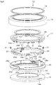
- FIG. 1 is an exploded perspective view showing a switch device according to the first embodiment
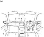
- FIG. 2 is a perspective view showing a front portion of the vehicle compartment
- FIG. 3 is a block diagram showing an electrical configuration
- FIG. 4 is a cross-sectional view schematically showing the switch device
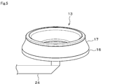
- FIG. 5 is a perspective view of the switch device
- FIG. 6 is an exploded perspective view of the switch device according to the second embodiment
- FIG. 7 is a perspective view showing a push ring and a rotating ring in combination with the knob base
- FIG. 8 is a sectional view showing a strained state in the third embodiment
- FIG. 9 is a side view showing the adhesive base in the fourth embodiment
- FIG. 10 is a plan view showing the adhesive base
- FIG. 11 is a side view showing the knob base
- FIG. 12 is a plan view showing the knob base
- FIG. 13 is a diagram showing a direction in which the operating force acts in the fifth embodiment
- FIG. 14 is a cross-sectional view showing the engagement structure
- FIG. 15 is a sectional view schematically showing the switch device.
- FIG. 2 An instrument panel 3 is provided in a portion in front of the driver's seat 1 and the passenger seat 2 in the vehicle interior.
- a CID (Center Information Display) 4 is provided at the center of the instrument panel 3.
- the CID 4 is an information display device having functions such as an air conditioner, a navigation system, an audio system, and a telephone.
- the video signal generator 5 outputs a predetermined video signal to the display 7 of the CID 4 according to a command from the display ECU 6.
- the display 7 is composed of, for example, a full-color liquid crystal and a backlight, and receives a video signal from the video signal generator 5 to display a predetermined video.
- the display 7 displays a navigation screen that displays the current position and traveling direction of the vehicle in a manner overlapping the surrounding road map, displays an audio operation screen, and allows the user to input and set various instructions.
- a menu selection screen for displaying and various messages are displayed.
- the user is a concept including not only the driver but also passengers in the front passenger seat and the rear seat.
- the display ECU 6 is connected to various ECUs such as a navigation ECU 8, an audio ECU 9, an air conditioner ECU 10 and the like via an in-vehicle network 11, and transmits/receives information to/from these ECUs 8-10.
- ECUs such as a navigation ECU 8, an audio ECU 9, an air conditioner ECU 10 and the like via an in-vehicle network 11, and transmits/receives information to/from these ECUs 8-10.
- the display ECU 6 identifies the process requested by the user based on the position information from the switch group 12 arranged around the CID 4 as shown in FIG. 2 and a touch sensor (not shown), and processes the process on the ECU 8 to 10 to be processed. Command.
- Each of the ECUs 8 to 10 executes navigation processing, audio processing, and air conditioning processing in response to a command from the display ECU 6.
- the switch device 13 is mounted on the surface of the CID 4, and the display ECU 6 selects or determines the control target based on the detection signal input from the switch device 13.
- the case 14 holds a panel 15 (corresponding to a surface member) that functions as an overlay, and functions as a reinforcing member for fixing the panel 15.
- the display 7 is arranged inside the case 14.
- the switch device 13 is configured by combining an adhesive base 16 and a knob assembly 17 (corresponding to an operation knob assembly) as shown in FIG.
- the adhesive base 16 is adhered to the surface of the panel 15 with an adhesive, and the knob assembly 17 is connected to the adhesive base 16.
- the knob assembly 17 includes an aluminum ring 18, a dial knob 19 (corresponding to an operation knob), a reflector 20, a plunger 21, a spring 22, an optical sensor 23 (corresponding to a detecting unit), and an FPC (Flexible printed). circuits) 24 (corresponding to an output section) and a knob base section 25 (corresponding to an operation knob base section).
- FIG. 4 schematically shows the electric components.
- the adhesive base 16 is a disc-shaped resin molded product, and an annular groove portion 26 is formed on the back side thereof as shown in FIG.
- the adhesive base 16 is adhered to the surface of the panel 15 with an adhesive 27 applied to the annular groove 26.
- a double-sided tape having a strong adhesive force may be used.
- the panel 15 is formed of flat glass or transparent resin, but the shape of the surface may be flat or curved.
- the aluminum ring 18 shown in FIG. 1 functions as a design member by being mounted on the surface of the dial knob 19.
- the dial knob 19 is a resin molded product made of a relatively flexible resin (ABS or elastomer).
- a plurality of claws 19a are formed at the lower end of the outer peripheral surface of the dial knob 19, and the claws 19a are locked to the lower end of the outer peripheral surface of the knob base 25 so that the dial knob 19 is secured. It is attached to the knob base 25.
- the dial knob 19 may be made of metal as long as it can be locked to the knob base portion 25.
- Two optical sensors 23 are mounted on the FPC 24, and the optical sensor 23 and the reflector 20 constitute an increment type rotary encoder. That is, the reflection plate 20 is fixed to the back surface of the dial knob 19, and is positioned so that the optical sensor 23 projects light on the rotation locus of the reflection plate 20.
- Reflective parts and non-reflective parts are alternately formed on the reflective plate 20, and when the reflective parts are located in the light projection area from the optical sensor 23, the optical sensor 23 receives the light reflected by the reflective parts. .. Accordingly, the rotation amount of the reflection plate 20 can be detected based on the number of times the light reception signal is turned ON/OFF.
- the rotation detection method is not limited to the optical sensor, and a magnetic sensor, an electrostatic sensor, a 2WAY sensor, or an encoder may be used.
- the FPC 24 is fixed to a boss (not shown) formed on the bottom surface of the knob base 25.
- the FPC 24 passes through the hole 16b formed in the adhesive base 16 as shown in FIG. 1, and then is led out from the switch device 13 and connected to the display ECU 6 as shown in FIG.
- peaks and valleys are formed concentrically and alternately.
- the plunger 21 and the spring 22 are housed in a housing portion 25 a formed in the knob base portion 25.
- the plunger 21 functions as a moderating mechanism by being urged by the spring 22 on the rotation loci of the peak portion and the valley portion formed on the dial knob 19.
- a leaf spring method may be adopted instead of the plunger method as the detent mechanism.
- a cylindrical portion 16a (corresponding to a connecting portion) is formed so as to project from the adhesive base 16, and the cylindrical portion 16a is press-fitted into a hole portion 25b (corresponding to a connecting portion) formed in the knob base 25.
- a connecting structure other than press-fitting can be adopted, it is desirable to adopt a connecting structure that can be easily connected without using an adhesive member such as an adhesive or a double-sided tape.
- the adhesive base 16 is gripped by an automatic machine (not shown), a predetermined amount of adhesive is applied from the dispenser to the annular groove portion 26 with the adhesive base 16 turned upside down, and then turned upside down to bond the adhesive base 16 to the surface of the panel 15.
- a camera or the like is used to align the adhesive base 16 with the surface of the panel 15, but when an operator attaches the adhesive base 16 to the surface of the panel 15, a jig for alignment is used.
- the FPC 24 is fixed to the adhesive base 16, but in the case of a configuration in which the detection result of the sensor is not output, this step can be omitted.
- parts other than the adhesive base 16 are assembled in advance as a knob assembly 17 in a separate step, and the knob assembly 17 is connected to the adhesive base 16.
- the assembly process can be facilitated or can be automated.
- the switch device 13 can be mounted on the surface of the panel 15.
- the dial knob 19 rotates with respect to the knob base 25. Since the optical sensor 23 detects the rotation amount and the rotation direction of the dial knob 19, the detection result is output to the display ECU 6 via the FPC 24.
- the display ECU 6 switches the menu displayed on the display 7 according to the detection result, switches the button to be selected, and confirms the selection result. Specifically, audio, car navigation, or air conditioner is selected according to the rotating operation, a sound source is selected according to the selected menu, a destination is set, or a set temperature is set.
- the switch device 13 is composed of the adhesive base 16 and the knob assembly 17, and the adhesive base 16 is adhered to the surface of the panel 15 with an adhesive, the knob assembly 17 is connected to the adhesive base 16, so that the assembly is assembled.
- the switch device is adhered to the surface of the panel 15 with an adhesive, it becomes easier to perform alignment and load adjustment when the adhesive base 16 is adhered.
- the second embodiment will be described with reference to FIGS. 6 and 7.
- the second embodiment is characterized in that the dial knob 19 can be pressed.
- the knob assembly 17 includes a push ring 28, a rotary ring 29, a tact switch 30 (corresponding to a detecting portion), a spring 31 (corresponding to a biasing portion). are additionally configured, and these parts are assembled as components of the knob assembly 17.
- a plurality of tongue pieces 28a are formed on the push ring 28, and the tongue pieces 28a are attached to the knob base 25 in a state of respectively entering the plurality of grooves 29a formed on the rotating ring 29.
- the width of the groove portion 29a is set to be larger than the width of the tongue piece portion 28a, and the rotary ring 29 can rotate with respect to the push ring 28 by an amount of play.
- the push ring 28 is formed with a ridge 28b, and the ridge 28b is fitted to the notch 25c formed in the knob base 25 to be attached to the knob base 25 (see FIG. 7). .. As a result, the push ring 28 is prevented from rotating with respect to the knob base portion 25.
- a push portion 28c is formed on the push ring 28, and the push portion 28c abuts an inclined portion 29c formed on the rotating ring 29.
- the pressing portion 28c moves in the pressing direction (downward in the drawing)
- the pressing portion 28c presses the inclined portion 29c, and the rotating ring 29 rotates with respect to the knob base 25.
- the FPC 24 has a folded portion 27a, and the tact switch 30 is mounted on the folded portion 27a.
- a protrusion (not shown) formed on the knob base 25 enters the folded-back portion 27a. Thereby, the tact switch 30 is positioned.
- a vertical standing portion 29d is formed on the rotary ring 29, and the standing portion 29d faces the tact switch 30.
- the standing portion 29d rotates with the rotation of the rotating ring 29 to press the tact switch 30.
- the tact switch 30 is turned on by being pressed, and when it is turned on, a tactile sensation is provided. With the above configuration, the tact switch 30 is turned on by the pressing operation on the dial knob 19, so that the pressing operation on the dial knob 19 can be detected.
- the spring 31 is interposed between the rotating ring 29 and the standing portion 25d formed on the knob base 25, and applies a biasing force to the rotating ring 29 to the initial position.
- a cylindrical outer peripheral surface centered on the central axis is provided with peaks and troughs (not shown) alternately concentrically formed.
- the plunger 21 functions as a moderating mechanism by being urged by the spring 31 on the rotation loci of the peak and the valley.
- a leaf spring method may be adopted instead of the plunger method as the detent mechanism.
- the rotary ring 29 rotates and presses the tact switch 30.
- the tact switch 30 is turned on, so that the operation can be confirmed by pressing the dial knob 19.
- the switch device 13 is configured to be able to perform a pressing operation in addition to a rotating operation, it is possible to expand the types of switch devices to which the present invention can be applied.
- the material of the surface of the panel 15 schematically shown in FIG. 8 is glass and the material of the adhesive base 16 is resin, a stress is applied to the adhesive surface of the adhesive material 27 due to a temperature change due to a difference in linear expansion coefficient between the two. Therefore, stress may be applied to the adhesive or the interface to cause distortion, and the adhesive force of the switch device 13 to the surface of the panel 15 may be reduced or the switch device 13 may drop off.
- the adhesive base 16 is made of, for example, a sheet metal such as SECC or SUS, a die-molded product, or a metal insert-molded product. That is, the coefficient of linear expansion of metal (for example, 10 to 20 ⁇ 10 ⁇ 6 /° C.) is higher than that of resin (for example, 50 to 100 ⁇ 10 ⁇ 6 /° C.) and that of glass (for example, 9 ⁇ ). Since it is close to 10 ⁇ 6 /° C.), it is possible to suppress the difference in linear expansion coefficient between the surface of the panel 15 and the adhesive base 16. When the adhesive base 16 is formed of the same member as the panel 15, the linear expansion coefficients of both are the same, and therefore the influence due to the temperature change does not occur at all. If the overlay to which the adhesive base 16 is attached is resin, the adhesive base 16 is made of resin.
- the adhesive base 16 is made of a material that is the same as or close to the linear expansion coefficient of the surface of the panel 15, the strain generated on the adhesive surface of the adhesive material 27 is suppressed and the adhesion is improved.
- the reliability can be improved.
- a fourth embodiment will be described with reference to FIGS. 9 to 12.
- the fourth embodiment is characterized in that the adhesive base 16 and the knob base 25 can be connected in a positioned state.
- the dial knob 19 often has a vertically and horizontally symmetrical structure, which makes positioning and orientation difficult. Further, there is a problem that it is difficult to fix the jig due to the rotation function and the pressing function and it is difficult to apply a load at the time of bonding.
- the adhesive base 16 is basically a component that is not visible to the user (not a design component), it is easy to form a notch or surface used for positioning, holding, and pressing, so the adhesive base 16 and the knob base
- the connection structure with 25 was devised.
- the adhesive base 16 is formed of a transparent material such as glass and printing or etching for positioning is provided on the back surface of the adhesive base 16, the positioning can be performed visually, so that the adhesive base 16 is used for positioning, holding, and pressing.
- the notches and faces for can be omitted.
- a plurality of hook portions 16c (corresponding to connecting portions) and protrusions 16d are provided upright on the periphery of the adhesive base 16.
- the hook portion 16c is formed at a position that is point-symmetric with respect to the central axis, but the protrusion 16d is formed at a position that is asymmetric.
- the connecting position of the knob base 25 with respect to the adhesive base 16 is indefinite only with the hook portion 16c, and thus the connecting position is regulated by the protrusion 16d.
- a groove 25e is formed on the outer peripheral surface of the knob base 25 at a portion corresponding to the hook 16c of the adhesive base 16, and a claw 25f (corresponding to a connecting portion) is formed in the groove 25e.
- a groove 25g is formed in a portion that is formed and faces the protrusion 16d.
- the knob base 25 has a hole 25h through which the FPC 24 passes.
- the hook portion 16c of the adhesive base 16 engages with the claw portion 25f of the knob base portion 25, and the protrusion 16d of the adhesive base 16 fits into the groove portion 25g of the knob base portion 25.
- the hook portion 16c of the adhesive base 16 engaged with the claw portion of the knob base portion 25 is flush with the outer peripheral surface of the knob base portion 25, but need not be flush.
- the knob assembly 17 can be easily connected to the adhesive base 16 in a aligned state. it can. Since the adhesive base 16 and the knob base 25 are connected by engagement, they can be mechanically and reliably connected.
- the fifth embodiment will be described with reference to FIGS. 13 to 15.
- the fifth embodiment is to suppress the connecting force of the knob assembly 17 connected to the adhesive base 16.
- the adhesive strength does not become a problem because a strong external force is not applied to the surface of the panel 15.
- the CID 4 in which the switch device 13 is mounted on the surface of the panel 15 it is required that the CID 4 does not break down when a force is applied by the dial operation of the user.
- an external force is applied to the surface of the panel 15 by a user operation, so it is necessary to worry about the adhesive strength between the case 14 and the panel 15.
- the operation of 200N or more is performed by the user operation based on ergonomics.
- the adhesion B between the case 14 and the panel 15 is required to have a narrow width because the design property of the narrow frame is required, but it is often difficult to withstand 200 N with a narrow width.
- connection between the adhesive base 16 and the knob assembly 17 removable so that rework and replacement are easy. That is, before the above-mentioned bonded portion is destroyed, if a predetermined force of, for example, 150 N or more is applied to the knob assembly 17, the knob assembly 17 may come off the adhesive base 16 to cause a fatal failure in the CID 4. I tried to prevent it.
- a connecting structure include a structure in which the engaging force is suppressed in place of the strong engagement between the hook portion and the claw portion, a structure in which the connecting force by the plunger is suppressed, a connecting structure by a magnet, and the like, and the load at the time of dropping is A connection structure that can be easily adjusted is considered.
- the claw portion 25f of the knob base portion 25 described in the fourth embodiment has a hemispherical bulging shape, and the adhesive base 16 has the same shape.
- the hook portion 16c By forming the hook portion 16c into a hemispherical depressed shape, the connecting force can be suppressed and the hook portion 16c can be more easily detached.
- a plunger instead of the claw portion, it is possible to realize a structure in which the connecting force is suppressed.
- FIG. 15 by fixing the magnets 32 having opposite polarities to the adhesive base 16 and the knob base 25 and connecting the magnets 32 to each other, a structure in which the connecting force is suppressed can be realized.
- the FPC 24 can be temporarily fixed to the adhesive base 16 to prevent disconnection of the FPC 24 when the knob assembly 17 comes off the adhesive base 16.
- connection force between the adhesive base 16 and the knob assembly 17 is set so that the knob assembly 17 is detached from the adhesive base 16 before the knob assembly 17 affects the CID. It is possible to reliably prevent the CID 4 from being destroyed even when a large external force is applied.
- the configuration may be such that the central portion of the switch device is closed.
- the switch device may be provided on a display other than CID4.
- the switch device may have a configuration capable of performing only a pressing operation, a configuration capable of performing a swinging operation or a sliding operation, or a configuration having a combination thereof.
Landscapes
- Engineering & Computer Science (AREA)
- Mechanical Engineering (AREA)
- Chemical & Material Sciences (AREA)
- Combustion & Propulsion (AREA)
- Transportation (AREA)
- Physics & Mathematics (AREA)
- General Physics & Mathematics (AREA)
- Automation & Control Theory (AREA)
- Rotary Switch, Piano Key Switch, And Lever Switch (AREA)
- Switch Cases, Indication, And Locking (AREA)
- Push-Button Switches (AREA)
- Switches With Compound Operations (AREA)
Priority Applications (2)
| Application Number | Priority Date | Filing Date | Title |
|---|---|---|---|
| CN201980077539.8A CN113168985A (zh) | 2018-11-29 | 2019-10-30 | 开关装置 |
| US17/324,853 US11756754B2 (en) | 2018-11-29 | 2021-05-19 | Switch device |
Applications Claiming Priority (2)
| Application Number | Priority Date | Filing Date | Title |
|---|---|---|---|
| JP2018-223561 | 2018-11-29 | ||
| JP2018223561A JP7077924B2 (ja) | 2018-11-29 | 2018-11-29 | スイッチ装置 |
Related Child Applications (1)
| Application Number | Title | Priority Date | Filing Date |
|---|---|---|---|
| US17/324,853 Continuation US11756754B2 (en) | 2018-11-29 | 2021-05-19 | Switch device |
Publications (1)
| Publication Number | Publication Date |
|---|---|
| WO2020110579A1 true WO2020110579A1 (ja) | 2020-06-04 |
Family
ID=70852101
Family Applications (1)
| Application Number | Title | Priority Date | Filing Date |
|---|---|---|---|
| PCT/JP2019/042572 Ceased WO2020110579A1 (ja) | 2018-11-29 | 2019-10-30 | スイッチ装置 |
Country Status (4)
| Country | Link |
|---|---|
| US (1) | US11756754B2 (enExample) |
| JP (1) | JP7077924B2 (enExample) |
| CN (1) | CN113168985A (enExample) |
| WO (1) | WO2020110579A1 (enExample) |
Families Citing this family (2)
| Publication number | Priority date | Publication date | Assignee | Title |
|---|---|---|---|---|
| US12050481B1 (en) * | 2023-01-31 | 2024-07-30 | Haier Us Appliance Solutions, Inc. | Systems for knob lockout on appliances |
| DE102024118903A1 (de) | 2024-07-03 | 2026-01-08 | Preh Gmbh | Bedienelement mit einer drehbeweglich und schwenkbeweglich betätigbaren Handhabe, zugehörige Mittelkonsole für ein Kraftfahrzeug und Verwendung |
Citations (5)
| Publication number | Priority date | Publication date | Assignee | Title |
|---|---|---|---|---|
| JPH10228843A (ja) * | 1997-02-13 | 1998-08-25 | Sony Corp | スイッチ装置 |
| JP2012134026A (ja) * | 2010-12-22 | 2012-07-12 | Tokyo Parts Ind Co Ltd | プッシュスイッチ及びその製造方法 |
| WO2015159494A1 (ja) * | 2014-04-14 | 2015-10-22 | パナソニックIpマネジメント株式会社 | 入力装置 |
| WO2017094234A1 (ja) * | 2015-12-04 | 2017-06-08 | パナソニックIpマネジメント株式会社 | 入力装置と、これを用いた入力システム |
| JP2018004493A (ja) * | 2016-07-04 | 2018-01-11 | 株式会社デンソー | 車両用表示装置 |
Family Cites Families (14)
| Publication number | Priority date | Publication date | Assignee | Title |
|---|---|---|---|---|
| FI93502C (fi) * | 1993-08-13 | 1995-04-10 | Abb Stroemberg Kojeet Oy | Kytkinlaite |
| MY120975A (en) | 1997-02-13 | 2005-12-30 | Sony Corp | Switch device. |
| EP1367618A3 (en) * | 2002-05-31 | 2005-04-20 | Polymatech Co., Ltd. | Indicator portion forming method for push switch and push switch having an indicator portion |
| JP3838170B2 (ja) * | 2002-07-08 | 2006-10-25 | 株式会社デンソー | スイッチ構造 |
| JP4062046B2 (ja) * | 2002-10-16 | 2008-03-19 | オムロン株式会社 | 入力装置および電子機器 |
| JP2007299037A (ja) | 2006-04-27 | 2007-11-15 | Alps Electric Co Ltd | 座標入力装置 |
| JP4551915B2 (ja) * | 2007-07-03 | 2010-09-29 | ホシデン株式会社 | 複合操作型入力装置 |
| JP2009224057A (ja) * | 2008-03-13 | 2009-10-01 | Alps Electric Co Ltd | ストークスイッチ装置 |
| JP5626591B2 (ja) * | 2011-04-14 | 2014-11-19 | アルプス電気株式会社 | 入力装置 |
| US10318078B2 (en) | 2014-05-15 | 2019-06-11 | Panasonic Intellectual Property Management Co., Ltd. | Operation knob and display device in which same is used |
| JP6121376B2 (ja) | 2014-10-08 | 2017-04-26 | 株式会社スクウェア・エニックス | ネットワークゲームシステム、ゲーム装置、及びプログラム |
| US10510501B2 (en) * | 2017-04-19 | 2019-12-17 | Danfoss Power Solutions Inc. | Rotary knob controller |
| JP6408652B1 (ja) * | 2017-05-30 | 2018-10-17 | トキワ工業株式会社 | 包装フィルム加工装置、包装機、および、包装フィルム加工方法 |
| CN207474352U (zh) * | 2017-12-13 | 2018-06-08 | 信利光电股份有限公司 | 一种旋钮开关 |
-
2018
- 2018-11-29 JP JP2018223561A patent/JP7077924B2/ja active Active
-
2019
- 2019-10-30 WO PCT/JP2019/042572 patent/WO2020110579A1/ja not_active Ceased
- 2019-10-30 CN CN201980077539.8A patent/CN113168985A/zh not_active Withdrawn
-
2021
- 2021-05-19 US US17/324,853 patent/US11756754B2/en active Active
Patent Citations (5)
| Publication number | Priority date | Publication date | Assignee | Title |
|---|---|---|---|---|
| JPH10228843A (ja) * | 1997-02-13 | 1998-08-25 | Sony Corp | スイッチ装置 |
| JP2012134026A (ja) * | 2010-12-22 | 2012-07-12 | Tokyo Parts Ind Co Ltd | プッシュスイッチ及びその製造方法 |
| WO2015159494A1 (ja) * | 2014-04-14 | 2015-10-22 | パナソニックIpマネジメント株式会社 | 入力装置 |
| WO2017094234A1 (ja) * | 2015-12-04 | 2017-06-08 | パナソニックIpマネジメント株式会社 | 入力装置と、これを用いた入力システム |
| JP2018004493A (ja) * | 2016-07-04 | 2018-01-11 | 株式会社デンソー | 車両用表示装置 |
Also Published As
| Publication number | Publication date |
|---|---|
| JP2020087820A (ja) | 2020-06-04 |
| JP7077924B2 (ja) | 2022-05-31 |
| CN113168985A (zh) | 2021-07-23 |
| US20210272762A1 (en) | 2021-09-02 |
| US11756754B2 (en) | 2023-09-12 |
Similar Documents
| Publication | Publication Date | Title |
|---|---|---|
| US6198475B1 (en) | Touch operation information output device | |
| US7312411B2 (en) | Electronic apparatus | |
| CN106462278A (zh) | 操作旋钮及利用该操作旋钮的显示装置 | |
| US20130002608A1 (en) | Human-machine interface | |
| JP5972627B2 (ja) | 枠部材、車載表示装置用枠部材、車載表示装置 | |
| US11756754B2 (en) | Switch device | |
| US20160077601A1 (en) | Input system for on-board use | |
| EP3370242B1 (en) | Vehicular multi-operating switch unit | |
| US6118434A (en) | Module structure | |
| JP2018503110A (ja) | 自動車用の表示装置 | |
| CN108705975B (zh) | 后视镜 | |
| US20080048649A1 (en) | Thin input device and mobile terminal equipped with the same | |
| US9734967B2 (en) | Operating panel device | |
| US9937793B2 (en) | Three dimensional view interactive activation system to deploy information | |
| JP3996144B2 (ja) | 2段スイッチユニット | |
| JP2000222126A (ja) | タッチパネルを備えた表示装置 | |
| JP2001310740A (ja) | 車両のハンドル用スイッチユニット | |
| JP6033016B2 (ja) | ステアリングスイッチ、ステアリングホイール | |
| CN114368286B (zh) | 投影切换装置 | |
| KR20190007802A (ko) | 차량 후석용 다기능 스위치 유닛 | |
| JP2010080121A (ja) | 入力装置及び電子機器 | |
| JP2022042860A (ja) | タッチパネル装置 | |
| JP3476534B2 (ja) | 操作装置 | |
| CN214202330U (zh) | 触摸屏显示器 | |
| JP2005158579A (ja) | 電子機器 |
Legal Events
| Date | Code | Title | Description |
|---|---|---|---|
| 121 | Ep: the epo has been informed by wipo that ep was designated in this application |
Ref document number: 19889260 Country of ref document: EP Kind code of ref document: A1 |
|
| NENP | Non-entry into the national phase |
Ref country code: DE |
|
| 122 | Ep: pct application non-entry in european phase |
Ref document number: 19889260 Country of ref document: EP Kind code of ref document: A1 |