WO2020105731A1 - 二次電池用負極活物質とその製造方法、および二次電池 - Google Patents
二次電池用負極活物質とその製造方法、および二次電池Info
- Publication number
- WO2020105731A1 WO2020105731A1 PCT/JP2019/045770 JP2019045770W WO2020105731A1 WO 2020105731 A1 WO2020105731 A1 WO 2020105731A1 JP 2019045770 W JP2019045770 W JP 2019045770W WO 2020105731 A1 WO2020105731 A1 WO 2020105731A1
- Authority
- WO
- WIPO (PCT)
- Prior art keywords
- negative electrode
- active material
- electrode active
- secondary battery
- silicon
- Prior art date
- Legal status (The legal status is an assumption and is not a legal conclusion. Google has not performed a legal analysis and makes no representation as to the accuracy of the status listed.)
- Ceased
Links
Images




Classifications
-
- H—ELECTRICITY
- H01—ELECTRIC ELEMENTS
- H01M—PROCESSES OR MEANS, e.g. BATTERIES, FOR THE DIRECT CONVERSION OF CHEMICAL ENERGY INTO ELECTRICAL ENERGY
- H01M4/00—Electrodes
- H01M4/02—Electrodes composed of, or comprising, active material
- H01M4/36—Selection of substances as active materials, active masses, active liquids
- H01M4/362—Composites
- H01M4/366—Composites as layered products
-
- H—ELECTRICITY
- H01—ELECTRIC ELEMENTS
- H01M—PROCESSES OR MEANS, e.g. BATTERIES, FOR THE DIRECT CONVERSION OF CHEMICAL ENERGY INTO ELECTRICAL ENERGY
- H01M4/00—Electrodes
- H01M4/02—Electrodes composed of, or comprising, active material
- H01M4/36—Selection of substances as active materials, active masses, active liquids
- H01M4/38—Selection of substances as active materials, active masses, active liquids of elements or alloys
- H01M4/386—Silicon or alloys based on silicon
-
- H—ELECTRICITY
- H01—ELECTRIC ELEMENTS
- H01M—PROCESSES OR MEANS, e.g. BATTERIES, FOR THE DIRECT CONVERSION OF CHEMICAL ENERGY INTO ELECTRICAL ENERGY
- H01M4/00—Electrodes
- H01M4/02—Electrodes composed of, or comprising, active material
- H01M4/13—Electrodes for accumulators with non-aqueous electrolyte, e.g. for lithium-accumulators; Processes of manufacture thereof
- H01M4/134—Electrodes based on metals, Si or alloys
-
- H—ELECTRICITY
- H01—ELECTRIC ELEMENTS
- H01M—PROCESSES OR MEANS, e.g. BATTERIES, FOR THE DIRECT CONVERSION OF CHEMICAL ENERGY INTO ELECTRICAL ENERGY
- H01M4/00—Electrodes
- H01M4/02—Electrodes composed of, or comprising, active material
- H01M4/13—Electrodes for accumulators with non-aqueous electrolyte, e.g. for lithium-accumulators; Processes of manufacture thereof
- H01M4/139—Processes of manufacture
- H01M4/1395—Processes of manufacture of electrodes based on metals, Si or alloys
-
- H—ELECTRICITY
- H01—ELECTRIC ELEMENTS
- H01M—PROCESSES OR MEANS, e.g. BATTERIES, FOR THE DIRECT CONVERSION OF CHEMICAL ENERGY INTO ELECTRICAL ENERGY
- H01M4/00—Electrodes
- H01M4/02—Electrodes composed of, or comprising, active material
- H01M4/36—Selection of substances as active materials, active masses, active liquids
- H01M4/362—Composites
- H01M4/364—Composites as mixtures
-
- H—ELECTRICITY
- H01—ELECTRIC ELEMENTS
- H01M—PROCESSES OR MEANS, e.g. BATTERIES, FOR THE DIRECT CONVERSION OF CHEMICAL ENERGY INTO ELECTRICAL ENERGY
- H01M4/00—Electrodes
- H01M4/02—Electrodes composed of, or comprising, active material
- H01M4/36—Selection of substances as active materials, active masses, active liquids
- H01M4/48—Selection of substances as active materials, active masses, active liquids of inorganic oxides or hydroxides
- H01M4/483—Selection of substances as active materials, active masses, active liquids of inorganic oxides or hydroxides for non-aqueous cells
-
- H—ELECTRICITY
- H01—ELECTRIC ELEMENTS
- H01M—PROCESSES OR MEANS, e.g. BATTERIES, FOR THE DIRECT CONVERSION OF CHEMICAL ENERGY INTO ELECTRICAL ENERGY
- H01M4/00—Electrodes
- H01M4/02—Electrodes composed of, or comprising, active material
- H01M4/36—Selection of substances as active materials, active masses, active liquids
- H01M4/58—Selection of substances as active materials, active masses, active liquids of inorganic compounds other than oxides or hydroxides, e.g. sulfides, selenides, tellurides, halogenides or LiCoFy; of polyanionic structures, e.g. phosphates, silicates or borates
- H01M4/583—Carbonaceous material, e.g. graphite-intercalation compounds or CFx
- H01M4/587—Carbonaceous material, e.g. graphite-intercalation compounds or CFx for inserting or intercalating light metals
-
- H—ELECTRICITY
- H01—ELECTRIC ELEMENTS
- H01M—PROCESSES OR MEANS, e.g. BATTERIES, FOR THE DIRECT CONVERSION OF CHEMICAL ENERGY INTO ELECTRICAL ENERGY
- H01M4/00—Electrodes
- H01M4/02—Electrodes composed of, or comprising, active material
- H01M4/62—Selection of inactive substances as ingredients for active masses, e.g. binders, fillers
-
- H—ELECTRICITY
- H01—ELECTRIC ELEMENTS
- H01M—PROCESSES OR MEANS, e.g. BATTERIES, FOR THE DIRECT CONVERSION OF CHEMICAL ENERGY INTO ELECTRICAL ENERGY
- H01M4/00—Electrodes
- H01M4/02—Electrodes composed of, or comprising, active material
- H01M4/62—Selection of inactive substances as ingredients for active masses, e.g. binders, fillers
- H01M4/624—Electric conductive fillers
- H01M4/625—Carbon or graphite
-
- B—PERFORMING OPERATIONS; TRANSPORTING
- B82—NANOTECHNOLOGY
- B82Y—SPECIFIC USES OR APPLICATIONS OF NANOSTRUCTURES; MEASUREMENT OR ANALYSIS OF NANOSTRUCTURES; MANUFACTURE OR TREATMENT OF NANOSTRUCTURES
- B82Y30/00—Nanotechnology for materials or surface science, e.g. nanocomposites
-
- C—CHEMISTRY; METALLURGY
- C01—INORGANIC CHEMISTRY
- C01B—NON-METALLIC ELEMENTS; COMPOUNDS THEREOF; METALLOIDS OR COMPOUNDS THEREOF NOT COVERED BY SUBCLASS C01C
- C01B32/00—Carbon; Compounds thereof
- C01B32/15—Nano-sized carbon materials
- C01B32/158—Carbon nanotubes
- C01B32/168—After-treatment
-
- H—ELECTRICITY
- H01—ELECTRIC ELEMENTS
- H01M—PROCESSES OR MEANS, e.g. BATTERIES, FOR THE DIRECT CONVERSION OF CHEMICAL ENERGY INTO ELECTRICAL ENERGY
- H01M4/00—Electrodes
- H01M4/02—Electrodes composed of, or comprising, active material
- H01M2004/026—Electrodes composed of, or comprising, active material characterised by the polarity
- H01M2004/027—Negative electrodes
-
- Y—GENERAL TAGGING OF NEW TECHNOLOGICAL DEVELOPMENTS; GENERAL TAGGING OF CROSS-SECTIONAL TECHNOLOGIES SPANNING OVER SEVERAL SECTIONS OF THE IPC; TECHNICAL SUBJECTS COVERED BY FORMER USPC CROSS-REFERENCE ART COLLECTIONS [XRACs] AND DIGESTS
- Y02—TECHNOLOGIES OR APPLICATIONS FOR MITIGATION OR ADAPTATION AGAINST CLIMATE CHANGE
- Y02E—REDUCTION OF GREENHOUSE GAS [GHG] EMISSIONS, RELATED TO ENERGY GENERATION, TRANSMISSION OR DISTRIBUTION
- Y02E60/00—Enabling technologies; Technologies with a potential or indirect contribution to GHG emissions mitigation
- Y02E60/10—Energy storage using batteries
Definitions
- the present invention relates to a negative electrode active material for a secondary battery, a method for manufacturing the same, and a secondary battery.
- the present application claims priority based on Japanese Patent Application No. 2018-219705 filed in Japan on November 22, 2018, and the content thereof is incorporated herein.
- alloy-based materials such as silicon are drawing attention as a new material replacing graphite of the conventional negative electrode material (for example, Non-Patent Documents 1 to 3).
- Silicon has a specific capacity almost four times larger than that of graphite, but has a large volume expansion when occluding lithium ions. Therefore, when silicon is used as the negative electrode material of the secondary battery, it is known that the active material particles are crushed due to the charge / discharge cycle of the secondary battery, and the capacity is deteriorated due to poor contact with the conductive additive.
- the present invention has been made in view of the above circumstances, while increasing the specific capacity, suppressing the film formation during the first charge reaction, crushing, it is possible to suppress capacity deterioration due to poor contact with the conductive additive,
- An object is to provide a negative electrode active material for a secondary battery.
- the present invention adopts the following means.
- a negative electrode active material for a secondary battery includes a silicon composite including a silicon compound and at least one carbon material selected from graphite, non-graphitizable carbon, and soft carbon, and A self-assembled monolayer that covers the surface of the silicon composite and has an amino group, and a carbon compound that is bonded to the self-assembled monolayer through the amino group and that contains a carbon atom as a main component. I have it.
- the silicon compound preferably accounts for 5% or more of the volume of the silicon composite.
- At least one of Si, SiO, and SiO x is the silicon compound as the silicon compound. It is preferably contained in the complex.
- the carbon compound body may be a carbon nanotube.
- the carbon compound body may be polyimide.
- the carbon compound body is polyvinylidene fluoride, polytetrafluoroethylene, ethylene-propylene-diene copolymer It may be made of at least one of a coalesced product, styrene-butadiene rubber, acrylonitrile-butadiene rubber, carboxymethyl cellulose, and fluororubber.
- a secondary battery according to one aspect of the present invention includes the negative electrode active material described in any one of (1) to (6).
- a method for producing a negative electrode active material for a secondary battery according to an aspect of the present invention is the method for producing a negative electrode active material for a secondary battery according to any one of (1) to (6).
- a step of forming a carbon compound body having a carboxyl group, a step of forming a silicon complex having an amino group, the carbon compound body and the silicon complex are mixed in a liquid, and the carboxyl group Bonding the amino group.
- a negative electrode active material for a secondary battery capable of increasing the specific capacity, suppressing the film formation during the initial charge reaction, and suppressing the capacity deterioration due to crushing and contact failure with the conductive additive. Can be provided.
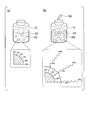
- FIG. 1 An enlarged cross-sectional surface view of a negative electrode for a secondary battery according to an embodiment of the present invention. It is some expanded sectional views of the negative electrode active material for secondary batteries of (b), (c), and (a). It is a figure explaining in detail about the manufacturing process of the negative electrode active material for rechargeable batteries concerning one embodiment of the present invention.
- (A), (b) It is a figure explaining typically about one method of forming a monomolecular film on a silicon complex.
- (A)-(d) It is a figure which illustrates typically the manufacturing process of the negative electrode active material for secondary batteries which concerns on one Embodiment of this invention.
- 3 (a) to (c) are graphs showing XPS analysis results for the negative electrode active materials for secondary batteries of Examples 1 and 2 and Comparative Example 1 of the present invention.
- 3 (a) to (d) are SEM images of negative electrode active materials for secondary batteries of Examples 2 and 4 of the present invention and Comparative Examples 2 and 3.
- (A) to (d) Graphs showing test results of constant current charge / discharge characteristics for R2032 coin type half cells using the negative electrode active materials for secondary batteries of Examples 2 and 4 and Comparative Examples 2 and 3 of the present invention. is there.
- 5 is a graph showing the discharge capacity cycle test results for R2032 coin type half cells using the negative electrode active materials for secondary batteries of Examples 2 and 4 and Comparative Examples 2 and 3 of the present invention.
- FIG. 5 is a graph showing the discharge capacity cycle test results for R2032 coin type half cells using the negative electrode active materials for secondary batteries of Examples 1, 3, 4 and Comparative Example 2 of the present invention.
- 9A to 9D are Nyquist plot graphs of the results of measurement by the AC impedance method after the cycle test of FIG. 8. It is a figure which shows the equivalent circuit model about the circuit used for the measurement of FIG. 9 is a SEM image of secondary battery negative electrode active materials of Examples 2 and 4 and Comparative Examples 2 and 3 obtained after the cycle test of FIG. 8.
- FIG. 1A is a cross-sectional view schematically showing a part of the configuration of a secondary battery negative electrode 100 including a secondary battery negative electrode active material 102 according to an embodiment of the present invention.
- the negative electrode 100 for a secondary battery is deposited (applied) so that a negative electrode active material 102 for a secondary battery forms a film on one surface 101a of a current collector 101 made of a conductive member such as a copper foil.
- a gap between the negative electrode active materials 102 is filled with a conductive auxiliary agent, a binder (binder), and the like.
- the negative electrode active material 102 for a secondary battery is a silicon composite 103 composed of a silicon compound and at least one carbon material of graphite, non-graphitizable carbon (hard carbon), or soft carbon, and the surface of the silicon composite 103. And a carbon compound body 105 bonded to the self-assembled monolayer 104.
- the silicon composite 103 contains at least one of Si, SiO, and SiO x (x is a real number) as a silicon compound.
- the silicon composite 103 may further contain Sn.
- the silicon compound occupy 5% or more of the volume of the silicon composite 103.
- the average diameter of the silicon compound (the average diameter of the particles of the silicon compound measured in all directions) is preferably 10 nm or more and 15000 nm or less.
- the silicon compound for example, composite particles obtained by dispersing nanosilicon particles having a particle size of about 100 nm in hollow soft carbon having a particle size of about 10 nm can be used.
- the volume ratio of nanosilicon to soft carbon is preferably 50:50.
- primary particles such as silicon oxide (SiO x ) particles having a particle diameter of approximately 10,000 nm and silicon oxide (SiO) having a particle diameter of approximately 1000 nm can be used.
- the self-assembled monolayer film 104 is a film made of a molecule such as carbon having an amino group (—NH 2 ) formed on the surface.
- the thickness T of the self-assembled monolayer 104 is preferably 1 nm or more and 10 nm or less.
- AHAMTES N-[(triethoxysilyl) methyl] -1,6-hexanediamine
- the carbon compound body 105 is a structure of a molecule containing a carbon atom as a main component, and examples thereof include carbon nanotubes (preferably multi-walled carbon nanotubes, which are not limited in length and thickness), graphene, Examples thereof include reduced graphene oxide, acetylene black, amorphous carbon, conductive materials such as conductive polymers, and binders such as polyimide and carboxymethyl cellulose.
- carbon nanotubes preferably multi-walled carbon nanotubes, which are not limited in length and thickness
- graphene examples thereof include reduced graphene oxide, acetylene black, amorphous carbon, conductive materials such as conductive polymers, and binders such as polyimide and carboxymethyl cellulose.
- FIG. 1B is an enlarged view of the region R 1 in the secondary battery negative electrode active material 102 of FIG. 1A.
- the secondary battery negative electrode active material 102 has a portion in which the monomolecular film 104 of the organic silane compound and the carbon nanotube 105A are non-covalently bonded. More specifically, in this portion, a positively charged functional group (—NH 3 + ) among amino groups formed in the self-assembled monolayer 104 and a carboxyl group formed in the carbon nanotube 105A are They are non-covalently bound by the attractive force associated with electrostatic interactions.
- FIG. 1C is an enlarged view of the region R 2 in the secondary battery negative electrode active material 102 of FIG. 1A.
- the secondary battery negative electrode active material 102 has a portion in which a plurality of carbon nanotubes 105A are bonded to a silicon compound monomolecular film 104 via an amino group. More specifically, in this portion, an amino group formed on the surface of the self-assembled monolayer 104 and a carboxyl group (—COOH) formed on the surface of the carbon nanotube 105A are linked with an amide bond (enclosed by a broken line). Part).
- binder examples include polyvinylidene fluoride (PVDF), polytetrafluoroethylene (PTFE), ethylene-propylene-diene copolymer (EPDM), styrene-butadiene rubber (SBR), acrylonitrile-butadiene rubber (NBR), polyimide (PI), carboxymethyl cellulose (CMC), fluororubber and the like.
- PVDF polyvinylidene fluoride
- PTFE polytetrafluoroethylene
- EPDM ethylene-propylene-diene copolymer
- SBR styrene-butadiene rubber
- NBR acrylonitrile-butadiene rubber
- PI polyimide
- CMC carboxymethyl cellulose
- Examples of the conductive auxiliary agent include Ketjen black, acetylene black, carbon black, graphite, carbon nanotube, carbon fiber, graphene, amorphous carbon, conductive polymer polyaniline, polypyrrole, polythiophene, polyacetylene, and polyacene. ..
- FIG. 2 is a diagram schematically illustrating a manufacturing process of the secondary battery negative electrode active material 102 according to the present embodiment.
- a carbon nanotube 105A having a carboxyl group (—COOH) formed on its surface is prepared, and a condensing agent such as EDC (1-ethyl-3- (3-dimethylaminopropyl) carbodiimide hydrochloride) 106 is added thereto,
- EDC 1-ethyl-3- (3-dimethylaminopropyl) carbodiimide hydrochloride
- the synthesized active ester compound 105B is reacted with a separately synthesized silicon complex 103 having an amino group (—NH 2 ) to form an amide bond between the carbon nanotube 105A and the silicon complex 103.
- the negative electrode active material 102 for a secondary battery can be obtained.
- the silicon complex 103 having an amino group can be synthesized by either a dry process or a wet process.
- the wet process is more preferable because the carbon nanotube adsorption reaction on the surface of the silicon complex particle is This is effective because it is easy to control the equilibrium with the self-assembly reaction of carbon nanotubes between silicon composite particles. Therefore, the bond between the amino group of the silicon composite 103 and the carboxyl group of the carbon nanotube 105A becomes strong, and peeling of the conductive additive and crushing of the active material itself due to volume expansion of silicon can be suppressed. As a result, the discharge capacity can be maintained high in the cycle test, as compared with the case of synthesizing by the dry process.
- FIGS. 3A and 3B are diagrams schematically explaining a wet process for synthesizing the silicon composite 103B having an amino group.
- the carboxyl group of the carbon nanotube 105A and the functional group (—NH 3 + ) that positively charges the amino group of the silicon composite 103 are attracted by electrostatic interaction. It will be non-covalently bound.
- the strength of the bond in this case is inferior to that in the case of forming an amide bond (covalent bond), but a predetermined effect can be obtained by covering the silicon composite 103 with the carbon nanotube 105A. Therefore, it is not essential to use the EDC to obtain the effects of this embodiment.
- the secondary battery negative electrode active material 102 contains silicon, the specific capacity can be increased nearly four times as compared with the conventional negative electrode active material made of graphite.
- the carbon compound covers the periphery of silicon, it is possible to prevent the formation of a film during the first charge reaction, and it is possible to suppress the volume expansion of silicon, the peeling of the conductive additive due to the volume expansion, the active material itself. It is possible to avoid problems specific to silicon-based active materials such as crushing. Therefore, when the secondary battery negative electrode active material 102 is used in a secondary battery for a long period of time, its reliability can be greatly improved.
- the configuration other than the negative electrode that is, the configuration of the positive electrode, the electrolytic solution, the separator, the case, etc. is not limited.
- a part of the active material particles contains silicon that undergoes vigorous volume expansion. By virtue of this, the gap between the active material particles is reduced, so that the amount of the insulating binder filling the gap can be reduced.
- negative electrode active materials for secondary batteries were produced under different conditions.
- Table 1 shows the mixing ratios of the silicon composite 103, the self-assembled monolayer 104, the multi-walled carbon nanotube (MWCNT) 105A, etc., contained in the secondary battery negative electrode active material 102 produced under each condition.
- MWCNT multi-walled carbon nanotube
- Example 1 A negative electrode including the negative electrode active material for a secondary battery as Example 1 was manufactured by the following procedures (steps 1 to 5).
- FIGS. 4A to 4D are diagrams schematically explaining each procedure.
- Step 1 First, as shown in FIG. 4 (a), water (H 2 O) contained in a container V 2 was mixed with multi-walled carbon nanotubes (MWCNT) 105A at room temperature so as to be 9 wt%, and carboxyl was added to the surface. A mixed liquid L 3 containing the multi-walled carbon nanotube 105A in which the group (—COOH) was formed was prepared. As the multi-walled carbon nanotube 105A, one having a length of 500 to 700 nm, a diameter of 15 to 20 nm, and 15 to 18 layers was used.
- MWCNT multi-walled carbon nanotubes
- Step 2 Further, a silicon composite 103 containing nanosilicon (n-Si) 104 at a weight ratio of 33% and graphite at 67% with respect to ethanol contained in another container was mixed at room temperature, and a hydroxyl group (- A mixed solution L 3 containing the silicon composite 103A in which (OH) was formed was prepared. Subsequently, 50 ⁇ L of aminoorganosilane was added to the same container and left overnight at room temperature to form a silicon complex in which an amino group (—NH 2 ) was formed through silicon to a hydroxyl group formed in the silicon complex 103A. A mixed solution L 4 containing 103B was prepared.
- Step 3 the mixed solution L 3 prepared in Step 1 as shown in FIG. 4 (b), the silicon complex 103B prepared in step 2 were mixed at room temperature, water W, multi-walled carbon nanotubes 105A, a silicon complex A mixed solution L5 of 103B was prepared. Multi-walled carbon nanotubes 105A of mixture L 5, for the weight ratio of the silicon composite 103, 1: 9 and was adjusted to.
- Step 4 Next, as shown in FIG. 4C, the produced mixed liquid L 6 was dropped on the current collector 101 made of a conductive member, and blade pressing was performed using the pressing member 109.
- a negative electrode 100 for a secondary battery having a negative electrode active material 102 for a secondary battery formed thereon was obtained.
- a plurality of granular silicon composites 103 containing nanosilicon are electrostatically interacted with the carbon nanotubes 105A through the self-assembled monolayer 104 covering the surface.
- the non-covalently bonded state is stacked (deposited) on the one surface 101a of the current collector due to the attractive force associated with.
- Example 2 A negative electrode including the negative electrode active material for a secondary battery as Example 2 was manufactured by changing only the procedure of Step 1 described above from Example 1. That is, in step 1, 1.5 mg of powdered EDC was mixed with water contained in the container together with the multi-walled carbon nanotubes to prepare a mixed liquid L 7 . The procedure of the other steps was the same as in Example 1.
- Example 3 A negative electrode including the negative electrode active material for a secondary battery as Example 3 was manufactured by the same procedure as in Example 1. However, the organic silane to be mixed was 200 ⁇ L.
- Example 4 A negative electrode including the negative electrode active material for a secondary battery as Example 4 was manufactured by the same procedure as in Example 2. However, the organic silane to be mixed was 200 ⁇ L.
- Comparative Example 1 A negative electrode including the negative electrode active material for a secondary battery as Comparative Example 1 was manufactured only by the procedures of Steps 2 and 4. That is, the mixed liquid for coating the current collector was produced without mixing the multi-walled carbon nanotube 105A. Therefore, the self-assembled monolayer having an amino group was exposed.
- Comparative example 2 A negative electrode provided with a negative electrode active material for a secondary battery as Comparative Example 2 was manufactured by a procedure that did not go through the above Step 2 (a procedure that goes through Steps 1, 3, and 4). That is, in the step 3, the mixed solution L 1 obtained in the step 1 was mixed with the silicon complex 103A having no amino group at room temperature.
- Comparative example 3 As a negative electrode including a negative electrode active material for a secondary battery as Comparative Example 3, nanosilicon (n-Si) not subjected to the above steps 1 to 3 was used, and the weight ratio of nanosilicon was 33% and graphite was 67%.
- a mixed NMP solution L 8 was prepared by mixing the silicon composite 103 containing the acetylene black and polyvinylidene fluoride at a weight ratio of 80:10:10, and the mixed NMP solution L 8 was prepared on the current collector by the same means as in step 4 above. Was coated and water was removed.
- FIGS. 5A to 5C are graphs showing the analysis results in Examples 1 and 2 and Comparative Example 1, respectively.
- the horizontal axis and the vertical axis of the graph represent the binding energy (eV) of the molecule and the spectral intensity (au), respectively.
- Table 2 shows the relative area ratios obtained by waveform-separating each spectrum.
- Example 1 From the comparison of the spectral intensities, the molecule (silicon complex) having the functional group (—NH 3 3+ ) in which the amino group was positively charged was contained in about 1.7 times as much as in Comparative Example 1. You can see that From this, it can be seen that most of the silicon composites in Example 1 are non-covalently bonded to the carboxyl groups of the multi-walled carbon nanotubes by the attractive force associated with electrostatic interaction.
- FIGS. 6A to 6D show the results of surface SEM observation of the negative electrodes for secondary batteries obtained in Examples 2 and 4 and Comparative Examples 2 and 3, respectively.
- the surface of the silicon composite particles in Example 2 is covered with the multi-walled carbon nanotubes, and the multi-walled carbon nanotubes are self-assembled in a bundle form between the silicon composite particles to cross-link the particles. .. From this, it can be seen that the silicon composite particles are non-covalently bonded to the carboxyl group of the multi-walled carbon nanotube by an attractive force associated with electrostatic interaction.
- Constant current charge / discharge characteristics of R2032 coin type half cells provided with an electrode made of the negative electrode active material for a secondary battery obtained in Examples 2 and 4 and Comparative Examples 2 and 3 and a counter electrode made of Li metal. The initial characteristic test was performed.
- the basis weight of the electrode was adjusted to about 0.5 mg / cm 2 per Si and the film thickness was about 20 ⁇ m, and the evaluation was performed without pressing.
- EC-DMC containing 1M LiPF 6 was used as the electrolytic solution.
- # 2400 manufactured by Celgard was used as the separator.
- the charge-discharge test was repeated 10 times under the conditions of a cutoff voltage range of 0.05 to 1.2 V (Li + / Li), a current density of 100 mA / g, and room temperature. At this time, the charge / discharge reaction was performed in CCCV mode and the discharge reaction was performed in CC mode.
- FIG. 8 is a graph showing test results. The horizontal axis and the vertical axis of the graph show the number of cycles (the number of times of repeating charging and discharging) and the discharge capacity (mAh / g), respectively.
- Example 4 The deterioration of the discharge capacity of Example 4 is suppressed to a small value at least in the number of cycles of 0 to 50, and the discharge capacity is higher than that of Example 3. This is because the negative electrode active material for a secondary battery of Example 4 was able to form more amide bonds between the silicon composite and the multi-walled carbon nanotubes as compared with Example 2, and the surface of the contained silicon was made stronger. This is because it can be protected.
- Comparative Example 2 contains a large amount of multi-walled carbon nanotubes, but it is only physically adsorbed to the surface of the silicon composite and is not amide-bonded, so the silicon composite is chemically immobilized. Since the volume expansion of silicon cannot be suppressed, the discharge capacity greatly deteriorates from the initial stage as a result of the increase in the peeling of the conductive auxiliary agent and the crushing of the active material itself due to the volume expansion. ..
- FIG. 9 is a graph showing the test results. The horizontal axis and the vertical axis of the graph are the same as in FIG.
- Example 4 The deterioration of the discharge capacity of Example 4 was suppressed to a small value at least in the number of cycles 0 to 50, and the discharge capacity was maintained higher than those of Examples 1 and 3 and Comparative Example 2. Further, no decrease in specific capacity due to increase in internal resistance due to increase in current density is observed. This is because the EDC used in Example 4 is more effective than Examples 1 and 3 in promoting the formation of an amide bond, the volume expansion of silicon is more strongly suppressed, and the EDC used as the conductive auxiliary agent accompanying the volume expansion is suppressed. This is because peeling and crushing of the active material itself can be greatly reduced.
- Example 3 containing more amino groups on the surface of the silicon composite suppressed the deterioration to be smaller, and even in the non-covalent bond accompanied by electrostatic attraction, the silicon was to some extent. It is possible to strongly suppress the volume expansion of the conductive material, and to greatly reduce the peeling of the conductive auxiliary agent and the crushing of the active material itself due to the volume expansion.
- FIG. 10 shows Nyquist plots measured by the alternating-current impedance method, which were measured after 5 and 50 charge / discharge cycle tests (After 5, After 50) under conditions of a current density of 500 mA / g.
- FIG. 11 is a diagram showing an equivalent circuit model of the circuit used in the measurement of FIG. Table 4 shows the impedance parameters (film resistance R SEI and electrolytic transfer resistance R CT ) analyzed by the equivalent circuit model.
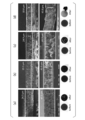
- 12A to 12D are cross-sectional SEMs of silicon composite negative electrodes measured in Examples 2 and 4 and Comparative Examples 2 and 3 under the condition of current density of 500 mA / g after 50 times of charge / discharge cycle test. It is a statue.
- Example 4 peeling from the current collector foil after 50 cycles was suppressed, and the change in film thickness was smaller than that before the cycle test.
- Comparative Examples 2 and 3 after the cycle test, many voids were seen at the interface with the current collector foil, indicating that they were peeled off.
Landscapes
- Chemical & Material Sciences (AREA)
- Chemical Kinetics & Catalysis (AREA)
- Electrochemistry (AREA)
- General Chemical & Material Sciences (AREA)
- Composite Materials (AREA)
- Inorganic Chemistry (AREA)
- Engineering & Computer Science (AREA)
- Materials Engineering (AREA)
- Manufacturing & Machinery (AREA)
- Battery Electrode And Active Subsutance (AREA)
- Nanotechnology (AREA)
- Organic Chemistry (AREA)
Abstract
Description
本願は、2018年11月22日に、日本に出願された特願2018-219705号に基づき優先権を主張し、その内容をここに援用する。
この場合のナノシリコンとソフトカーボンとの体積比は、50:50であることが好ましい。また、シリコン化合物としては、例えば、粒径が約10000nmの酸化シリコン(SiOx)粒子、粒径が約1000nmの酸化シリコン(SiO)等の一次粒子を用いることもできる。

実施例1としての二次電池用負極活物質を備えた負極を、次の手順(工程1~5)で製造した。図4(a)~(d)は、各手順について模式的に説明する図である。
まず、図4(a)に示すように、容器V2に収容した水(H2O)に対し、多層カーボンナノチューブ(MWCNT)105Aを、9wt%となるように室温で混合し、表面にカルボキシル基(-COOH)が形成された多層カーボンナノチューブ105Aを含む、混合液L3を作製した。多層カーボンナノチューブ105Aとしては、長さ500~700nm、直径15~20nm、15~18層のものを用いた。
また、別の容器に収容したエタノールに対し、ナノシリコン(n-Si)104を33%、黒鉛を67%の重量比で含むシリコン複合体103を、室温で混合し、表面にヒドロキシル基(-OH)が形成されたシリコン複合体103Aを含む、混合液L3を作製した。続いて、同容器にアミノ有機シランを50μL加え、室温で一晩放置し、シリコン複合体103Aに形成されたヒドロキシル基に、シリコンを介してアミノ基(-NH2)が形成されたシリコン複合体103Bを含む、混合液L4を作製した。
次に、図4(b)に示すように工程1で作製した混合液L3に、工程2で作製したシリコン複合体103Bを室温で混合して、水W、多層カーボンナノチューブ105A、シリコン複合体103Bの混合液L5を作製した。混合液L5中の多層カーボンナノチューブ105A、シリコン複合体103の重量比については、1:9となるように調製した。
次に、図4(c)に示すように、作製した混合液L6を導電部材からなる集電体101上に滴下し、押し当て部材109を用いてブレードコーティングを行った。
実施例2としての二次電池用負極活物質を備えた負極を、上記工程1の手順のみを実施例1と変えて製造した。すなわち、工程1において、容器に収容した水に対し、多層カーボンナノチューブとともに、1.5mgの粉末状のEDCを混合し、混合液L7を作製した。その他の工程の手順は、実施例1と同様とした。
実施例3としての二次電池用負極活物質を備えた負極を、実施例1と同様の手順で製造した。ただし、混合する有機シランを200μLとした。
実施例4としての二次電池用負極活物質を備えた負極を、実施例2と同様の手順で製造した。ただし、混合する有機シランを200μLとした。
比較例1としての二次電池用負極活物質を備えた負極を、上記工程2、4の手順のみで製造した。すなわち、集電体にコーティングする混合液を、多層カーボンナノチューブ105Aを混合せずに製造した。そのため、アミノ基を有する自己組織化単分子膜が露出した状態となった。
比較例2としての二次電池用負極活物質を備えた負極を、上記工程2を経ない手順(工程1、3、4を経る手順)で製造した。すなわち、上記工程3において、上記工程1で得た混合液L1に対し、アミノ基を有していないシリコン複合体103Aを、室温で混合した。
比較例3としての二次電池用負極活物質を備えた負極を、上記工程1~3を経ていないナノシリコン(n-Si)を用い、ナノシリコンを33%、黒鉛を67%の重量比で含むシリコン複合体103と、アセチレンブラックと、ポリフッ化ビニリデンとを重量比80:10:10で混合した混合NMP溶液L8を作製し、上記工程4と同様の手段により、これを集電体上にコーティングし、水の除去を行った。


101・・・集電体
101a・・・集電体の一面
102・・・二次電池用負極活物質
103、103A・・・シリコン複合体
104・・・自己組織化単分子膜
105・・・炭素化合物体
105A・・・カーボンナノチューブ
105B・・・活性エステル化合物
106・・・EDC
107・・・エタノール
108・・・アミノオルガノシラン
109・・・押し当て部材
L1~L8・・・混合液
R1、R2・・・領域
T・・・自己組織化単分子膜の厚さ
V1、V2・・・容器
W・・・水
Claims (10)
- シリコン化合物と黒鉛、難黒鉛化炭素、またはソフトカーボンのうち少なくとも一つの炭素材料とで構成されるシリコン複合体と、
前記シリコン複合体の表面を覆い、アミノ基を有する自己組織化単分子膜と、
前記アミノ基を介して前記自己組織化単分子膜と結合され、炭素原子を主成分として含む炭素化合物体と、を備えていることを特徴とする二次電池用負極活物質。 - 前記シリコン化合物は、前記シリコン複合体の体積の5%以上を占めていることを特徴とする請求項1に記載の二次電池用負極活物質。
- 前記シリコン化合物として、Si、SiO、SiOx(xは実数)のうち少なくとも一つが、前記シリコン複合体に含まれていることを特徴とする請求項1または2のいずれかに記載の二次電池用負極活物質。
- 前記炭素化合物体が、カーボンナノチューブであることを特徴とする請求項1~3のいずれか一項に記載の二次電池用負極活物質。
- 前記炭素化合物体が、ポリイミドであることを特徴とする請求項1~3のいずれか一項に記載の二次電池用負極活物質。
- 前記炭素化合物体が、ポリフッ化ビニリデン、ポリテトラフルオロエチレン、エチレン-プロピレン-ジエン共重合体、スチレン-ブタジエンゴム、アクリロニトリル-ブタジエンゴム、カルボキシルメチルセルロース、フッ素ゴムのうち、少なくとも一つからなることを特徴とする請求項1~3のいずれか一項に記載の二次電池用負極活物質。
- 請求項1~6のいずれか一項に記載の負極活物質を備えていることを特徴とする二次電池。
- 請求項1~6のいずれか一項に記載の二次電池用負極活物質の製造方法であって、
カルボキシル基を備えた炭素化合物体を形成する工程と、
アミノ基を備えたシリコン複合体を形成する工程と、
前記炭素化合物体と前記シリコン複合体とを液体中で混合し、前記カルボキシル基と前記アミノ基とを結合させる工程と、を有することを特徴とする二次電池用負極活物質の製造方法。 - 前記液体に、縮合剤を加えることを特徴とする請求項8に記載の二次電池用負極活物質の製造方法。
- 前記縮合剤として、1-エチル-3-(3-ジメチルアミノプロピル)カルボジイミド塩酸塩を用いること特徴とする請求項8または9のいずれかに記載の二次電池用負極活物質の製造方法。
Priority Applications (4)
| Application Number | Priority Date | Filing Date | Title |
|---|---|---|---|
| KR1020217007558A KR102731343B1 (ko) | 2018-11-22 | 2019-11-22 | 2차 전지용 음극 활물질과 그 제조 방법, 및 2차 전지 |
| CN201980061146.8A CN112889165A (zh) | 2018-11-22 | 2019-11-22 | 二次电池用负极活性物质及其制造方法和二次电池 |
| US17/275,022 US12537191B2 (en) | 2018-11-22 | 2019-11-22 | Negative electrode active material for rechargeable battery, method for producing the same, and rechargeable battery |
| JP2020557663A JP7313700B2 (ja) | 2018-11-22 | 2019-11-22 | 二次電池用負極活物質とその製造方法、および二次電池 |
Applications Claiming Priority (2)
| Application Number | Priority Date | Filing Date | Title |
|---|---|---|---|
| JP2018219705 | 2018-11-22 | ||
| JP2018-219705 | 2018-11-22 |
Publications (1)
| Publication Number | Publication Date |
|---|---|
| WO2020105731A1 true WO2020105731A1 (ja) | 2020-05-28 |
Family
ID=70773325
Family Applications (1)
| Application Number | Title | Priority Date | Filing Date |
|---|---|---|---|
| PCT/JP2019/045770 Ceased WO2020105731A1 (ja) | 2018-11-22 | 2019-11-22 | 二次電池用負極活物質とその製造方法、および二次電池 |
Country Status (5)
| Country | Link |
|---|---|
| US (1) | US12537191B2 (ja) |
| JP (1) | JP7313700B2 (ja) |
| KR (1) | KR102731343B1 (ja) |
| CN (1) | CN112889165A (ja) |
| WO (1) | WO2020105731A1 (ja) |
Cited By (2)
| Publication number | Priority date | Publication date | Assignee | Title |
|---|---|---|---|---|
| WO2022181151A1 (ja) * | 2021-02-25 | 2022-09-01 | パナソニックIpマネジメント株式会社 | リチウムイオン二次電池用負極、リチウムイオン二次電池、CNT-Siペーストの製造方法、リチウムイオン二次電池用負極の製造方法、リチウムイオン二次電池の製造方法 |
| WO2023176937A1 (ja) * | 2022-03-16 | 2023-09-21 | 国立大学法人信州大学 | 二次電池用負極活物質とその製造方法、二次電池用負極、および二次電池 |
Families Citing this family (4)
| Publication number | Priority date | Publication date | Assignee | Title |
|---|---|---|---|---|
| CN114927678A (zh) * | 2022-06-20 | 2022-08-19 | 南昌大学 | 一种硅负极材料的表面改性方法 |
| CN118830103B (zh) * | 2022-11-11 | 2026-01-13 | 宁德时代新能源科技股份有限公司 | 负极活性材料及其制备方法、二次电池及其制备方法、用电装置 |
| CN118299525B (zh) * | 2023-01-04 | 2026-01-27 | 宁德时代新能源科技股份有限公司 | 负极活性材料及制备方法和应用 |
| WO2024229157A1 (en) * | 2023-05-01 | 2024-11-07 | The Coretec Group Inc. | Si anode |
Citations (8)
| Publication number | Priority date | Publication date | Assignee | Title |
|---|---|---|---|---|
| JP2011049046A (ja) * | 2009-08-27 | 2011-03-10 | Nissan Motor Co Ltd | 電池用電極およびその製造方法 |
| CN103545493A (zh) * | 2013-11-01 | 2014-01-29 | 中南大学 | 一种硅/碳多元复合负极材料的制备方法 |
| JP2014070008A (ja) * | 2012-10-01 | 2014-04-21 | Showa Denko Kk | 複合材料の製造方法、および複合材料 |
| CN104319367A (zh) * | 2014-10-09 | 2015-01-28 | 奇瑞汽车股份有限公司 | 一种硅/石墨复合负极材料及其制备方法 |
| JP2016526264A (ja) * | 2013-05-23 | 2016-09-01 | ネキシオン リミテッド | 電気化学セル用表面処理シリコン含有活物質 |
| WO2016181890A1 (ja) * | 2015-05-08 | 2016-11-17 | 凸版印刷株式会社 | 非水電解質二次電池用電極および非水電解質二次電池 |
| US20170012278A1 (en) * | 2014-01-30 | 2017-01-12 | Robert Bosch Gmbh | Condensed silicon-carbon composite |
| US20180083268A1 (en) * | 2016-09-19 | 2018-03-22 | GM Global Technology Operations LLC | High performance silicon electrodes having improved interfacial adhesion between binder, silicon and conductive particles |
Family Cites Families (4)
| Publication number | Priority date | Publication date | Assignee | Title |
|---|---|---|---|---|
| KR101604081B1 (ko) * | 2009-01-30 | 2016-03-17 | 삼성전자주식회사 | 복합체 음극활물질, 이를 포함하는 음극, 이를 채용한 리튬전지 및 이의 제조 방법 |
| CN104577084A (zh) | 2015-01-20 | 2015-04-29 | 深圳市贝特瑞新能源材料股份有限公司 | 一种锂离子电池用纳米硅复合负极材料、制备方法及锂离子电池 |
| KR102368307B1 (ko) * | 2015-09-16 | 2022-03-02 | 삼성전자주식회사 | 전극 활물질, 이를 포함하는 전극 및 이차전지, 및 상기 전극 활물질의 제조방법 |
| CN105226253B (zh) * | 2015-10-16 | 2018-07-31 | 李家晓 | 一种纳米硅颗粒-石墨片-碳纳米管复合材料及其制备方法与应用 |
-
2019
- 2019-11-22 KR KR1020217007558A patent/KR102731343B1/ko active Active
- 2019-11-22 CN CN201980061146.8A patent/CN112889165A/zh active Pending
- 2019-11-22 US US17/275,022 patent/US12537191B2/en active Active
- 2019-11-22 WO PCT/JP2019/045770 patent/WO2020105731A1/ja not_active Ceased
- 2019-11-22 JP JP2020557663A patent/JP7313700B2/ja active Active
Patent Citations (8)
| Publication number | Priority date | Publication date | Assignee | Title |
|---|---|---|---|---|
| JP2011049046A (ja) * | 2009-08-27 | 2011-03-10 | Nissan Motor Co Ltd | 電池用電極およびその製造方法 |
| JP2014070008A (ja) * | 2012-10-01 | 2014-04-21 | Showa Denko Kk | 複合材料の製造方法、および複合材料 |
| JP2016526264A (ja) * | 2013-05-23 | 2016-09-01 | ネキシオン リミテッド | 電気化学セル用表面処理シリコン含有活物質 |
| CN103545493A (zh) * | 2013-11-01 | 2014-01-29 | 中南大学 | 一种硅/碳多元复合负极材料的制备方法 |
| US20170012278A1 (en) * | 2014-01-30 | 2017-01-12 | Robert Bosch Gmbh | Condensed silicon-carbon composite |
| CN104319367A (zh) * | 2014-10-09 | 2015-01-28 | 奇瑞汽车股份有限公司 | 一种硅/石墨复合负极材料及其制备方法 |
| WO2016181890A1 (ja) * | 2015-05-08 | 2016-11-17 | 凸版印刷株式会社 | 非水電解質二次電池用電極および非水電解質二次電池 |
| US20180083268A1 (en) * | 2016-09-19 | 2018-03-22 | GM Global Technology Operations LLC | High performance silicon electrodes having improved interfacial adhesion between binder, silicon and conductive particles |
Cited By (2)
| Publication number | Priority date | Publication date | Assignee | Title |
|---|---|---|---|---|
| WO2022181151A1 (ja) * | 2021-02-25 | 2022-09-01 | パナソニックIpマネジメント株式会社 | リチウムイオン二次電池用負極、リチウムイオン二次電池、CNT-Siペーストの製造方法、リチウムイオン二次電池用負極の製造方法、リチウムイオン二次電池の製造方法 |
| WO2023176937A1 (ja) * | 2022-03-16 | 2023-09-21 | 国立大学法人信州大学 | 二次電池用負極活物質とその製造方法、二次電池用負極、および二次電池 |
Also Published As
| Publication number | Publication date |
|---|---|
| KR20210092190A (ko) | 2021-07-23 |
| JP7313700B2 (ja) | 2023-07-25 |
| US12537191B2 (en) | 2026-01-27 |
| US20220069295A1 (en) | 2022-03-03 |
| JPWO2020105731A1 (ja) | 2021-11-11 |
| CN112889165A (zh) | 2021-06-01 |
| KR102731343B1 (ko) | 2024-11-18 |
Similar Documents
| Publication | Publication Date | Title |
|---|---|---|
| JP7313700B2 (ja) | 二次電池用負極活物質とその製造方法、および二次電池 | |
| JP7045032B2 (ja) | 支持フィラメントを含むハイブリッドエネルギー貯蔵デバイス | |
| US10020500B2 (en) | Carbonized polyaniline-grafted silicon nanoparticles encapsulated in graphene sheets for li-ion battery anodes | |
| TWI441376B (zh) | 鋰離子電池正極及鋰離子電池 | |
| KR102262387B1 (ko) | 하이브리드 에너지 저장 장치 | |
| CN104641500B (zh) | 包含石墨烯的电极配制物 | |
| JP2020019702A (ja) | ポリマー変性ケイ素−炭素複合材料及びその使用 | |
| CN110911640B (zh) | 多层阳极以及包含多层阳极的锂二次电池 | |
| US20200144597A1 (en) | Advanced negative electrode architecture for high power applications | |
| JP6894030B2 (ja) | 支持フィラメントを含むハイブリッドエネルギー貯蔵デバイス | |
| CN116914085A (zh) | 负极、非水电解质二次电池和负极的制造方法 | |
| CN113394363B (zh) | 负极极片的制备方法、负极极片、电池及电子装置 | |
| JP6844602B2 (ja) | 電極 | |
| JP7349349B2 (ja) | 非水電解質二次電池用負極、及び非水電解質二次電池 | |
| US20250197225A1 (en) | Negative Electrode Active Material for Secondary Battery, Manufacturing Method Thereof, Negative Electrode for Secondary Battery and Secondary Battery | |
| JP2024134740A (ja) | 正極板及び非水電解質二次電池 | |
| CN116895736A (zh) | 负极和非水电解质二次电池 | |
| CN118335982A (zh) | 导电材料分散液、利用该导电材料分散液制造的二次电池用负极及包括该负极的二次电池 | |
| CN118198265A (zh) | 非水电解质二次电池用负极及其制造方法 |
Legal Events
| Date | Code | Title | Description |
|---|---|---|---|
| 121 | Ep: the epo has been informed by wipo that ep was designated in this application |
Ref document number: 19886917 Country of ref document: EP Kind code of ref document: A1 |
|
| ENP | Entry into the national phase |
Ref document number: 2020557663 Country of ref document: JP Kind code of ref document: A |
|
| ENP | Entry into the national phase |
Ref document number: 20217007558 Country of ref document: KR Kind code of ref document: A |
|
| NENP | Non-entry into the national phase |
Ref country code: DE |
|
| 122 | Ep: pct application non-entry in european phase |
Ref document number: 19886917 Country of ref document: EP Kind code of ref document: A1 |
|
| WWG | Wipo information: grant in national office |
Ref document number: 17275022 Country of ref document: US |