WO2020105631A1 - 箱開梱装置及びそれを用いた箱開梱方法 - Google Patents
箱開梱装置及びそれを用いた箱開梱方法Info
- Publication number
- WO2020105631A1 WO2020105631A1 PCT/JP2019/045261 JP2019045261W WO2020105631A1 WO 2020105631 A1 WO2020105631 A1 WO 2020105631A1 JP 2019045261 W JP2019045261 W JP 2019045261W WO 2020105631 A1 WO2020105631 A1 WO 2020105631A1
- Authority
- WO
- WIPO (PCT)
- Prior art keywords
- box
- robot
- unpacking
- holding device
- cutting blade
- Prior art date
- Legal status (The legal status is an assumption and is not a legal conclusion. Google has not performed a legal analysis and makes no representation as to the accuracy of the status listed.)
- Ceased
Links
Images




Classifications
-
- B—PERFORMING OPERATIONS; TRANSPORTING
- B25—HAND TOOLS; PORTABLE POWER-DRIVEN TOOLS; MANIPULATORS
- B25J—MANIPULATORS; CHAMBERS PROVIDED WITH MANIPULATION DEVICES
- B25J9/00—Program-controlled manipulators
- B25J9/16—Program controls
- B25J9/1679—Program controls characterised by the tasks executed
-
- B—PERFORMING OPERATIONS; TRANSPORTING
- B25—HAND TOOLS; PORTABLE POWER-DRIVEN TOOLS; MANIPULATORS
- B25J—MANIPULATORS; CHAMBERS PROVIDED WITH MANIPULATION DEVICES
- B25J11/00—Manipulators not otherwise provided for
- B25J11/005—Manipulators for mechanical processing tasks
- B25J11/0055—Cutting
-
- B—PERFORMING OPERATIONS; TRANSPORTING
- B25—HAND TOOLS; PORTABLE POWER-DRIVEN TOOLS; MANIPULATORS
- B25J—MANIPULATORS; CHAMBERS PROVIDED WITH MANIPULATION DEVICES
- B25J13/00—Controls for manipulators
- B25J13/08—Controls for manipulators by means of sensing devices, e.g. viewing or touching devices
- B25J13/088—Controls for manipulators by means of sensing devices, e.g. viewing or touching devices with position, velocity or acceleration sensors
-
- B—PERFORMING OPERATIONS; TRANSPORTING
- B25—HAND TOOLS; PORTABLE POWER-DRIVEN TOOLS; MANIPULATORS
- B25J—MANIPULATORS; CHAMBERS PROVIDED WITH MANIPULATION DEVICES
- B25J15/00—Gripping heads and other end effectors
- B25J15/009—Gripping heads and other end effectors with pins for accurately positioning the object on the gripping head
-
- B—PERFORMING OPERATIONS; TRANSPORTING
- B25—HAND TOOLS; PORTABLE POWER-DRIVEN TOOLS; MANIPULATORS
- B25J—MANIPULATORS; CHAMBERS PROVIDED WITH MANIPULATION DEVICES
- B25J15/00—Gripping heads and other end effectors
- B25J15/02—Gripping heads and other end effectors servo-actuated
- B25J15/0206—Gripping heads and other end effectors servo-actuated comprising articulated grippers
-
- B—PERFORMING OPERATIONS; TRANSPORTING
- B26—HAND CUTTING TOOLS; CUTTING; SEVERING
- B26D—CUTTING; DETAILS COMMON TO MACHINES FOR PERFORATING, PUNCHING, CUTTING-OUT, STAMPING-OUT OR SEVERING
- B26D1/00—Cutting through work characterised by the nature or movement of the cutting member or particular materials not otherwise provided for; Apparatus or machines therefor; Cutting members therefor
- B26D1/01—Cutting through work characterised by the nature or movement of the cutting member or particular materials not otherwise provided for; Apparatus or machines therefor; Cutting members therefor involving a cutting member which does not travel with the work
- B26D1/02—Cutting through work characterised by the nature or movement of the cutting member or particular materials not otherwise provided for; Apparatus or machines therefor; Cutting members therefor involving a cutting member which does not travel with the work having a stationary cutting member
- B26D1/025—Cutting through work characterised by the nature or movement of the cutting member or particular materials not otherwise provided for; Apparatus or machines therefor; Cutting members therefor involving a cutting member which does not travel with the work having a stationary cutting member for thin material, e.g. for sheets, strips or the like
-
- B—PERFORMING OPERATIONS; TRANSPORTING
- B26—HAND CUTTING TOOLS; CUTTING; SEVERING
- B26D—CUTTING; DETAILS COMMON TO MACHINES FOR PERFORATING, PUNCHING, CUTTING-OUT, STAMPING-OUT OR SEVERING
- B26D1/00—Cutting through work characterised by the nature or movement of the cutting member or particular materials not otherwise provided for; Apparatus or machines therefor; Cutting members therefor
- B26D1/01—Cutting through work characterised by the nature or movement of the cutting member or particular materials not otherwise provided for; Apparatus or machines therefor; Cutting members therefor involving a cutting member which does not travel with the work
- B26D1/12—Cutting through work characterised by the nature or movement of the cutting member or particular materials not otherwise provided for; Apparatus or machines therefor; Cutting members therefor involving a cutting member which does not travel with the work having a cutting member moving about an axis
- B26D1/14—Cutting through work characterised by the nature or movement of the cutting member or particular materials not otherwise provided for; Apparatus or machines therefor; Cutting members therefor involving a cutting member which does not travel with the work having a cutting member moving about an axis with a circular cutting member, e.g. disc cutter
- B26D1/143—Cutting through work characterised by the nature or movement of the cutting member or particular materials not otherwise provided for; Apparatus or machines therefor; Cutting members therefor involving a cutting member which does not travel with the work having a cutting member moving about an axis with a circular cutting member, e.g. disc cutter rotating about a stationary axis
- B26D1/1435—Cutting through work characterised by the nature or movement of the cutting member or particular materials not otherwise provided for; Apparatus or machines therefor; Cutting members therefor involving a cutting member which does not travel with the work having a cutting member moving about an axis with a circular cutting member, e.g. disc cutter rotating about a stationary axis for thin material, e.g. for sheets, strips or the like
-
- B—PERFORMING OPERATIONS; TRANSPORTING
- B26—HAND CUTTING TOOLS; CUTTING; SEVERING
- B26D—CUTTING; DETAILS COMMON TO MACHINES FOR PERFORATING, PUNCHING, CUTTING-OUT, STAMPING-OUT OR SEVERING
- B26D5/00—Arrangements for operating and controlling machines or devices for cutting, cutting-out, stamping-out, punching, perforating, or severing by means other than cutting
- B26D5/02—Means for moving the cutting member into its operative position for cutting
-
- B—PERFORMING OPERATIONS; TRANSPORTING
- B65—CONVEYING; PACKING; STORING; HANDLING THIN OR FILAMENTARY MATERIAL
- B65B—MACHINES, APPARATUS OR DEVICES FOR, OR METHODS OF, PACKAGING ARTICLES OR MATERIALS; UNPACKING
- B65B69/00—Unpacking of articles or materials, not otherwise provided for
- B65B69/0033—Unpacking of articles or materials, not otherwise provided for by cutting
-
- B—PERFORMING OPERATIONS; TRANSPORTING
- B26—HAND CUTTING TOOLS; CUTTING; SEVERING
- B26D—CUTTING; DETAILS COMMON TO MACHINES FOR PERFORATING, PUNCHING, CUTTING-OUT, STAMPING-OUT OR SEVERING
- B26D1/00—Cutting through work characterised by the nature or movement of the cutting member or particular materials not otherwise provided for; Apparatus or machines therefor; Cutting members therefor
- B26D1/01—Cutting through work characterised by the nature or movement of the cutting member or particular materials not otherwise provided for; Apparatus or machines therefor; Cutting members therefor involving a cutting member which does not travel with the work
- B26D1/46—Cutting through work characterised by the nature or movement of the cutting member or particular materials not otherwise provided for; Apparatus or machines therefor; Cutting members therefor involving a cutting member which does not travel with the work having an endless band-knife or the like
Definitions
- the present invention relates to an apparatus for unpacking a packed and sealed box and taking out the contents in the box, and a method using the same.
- Patent Document 1 and the like propose a device including a robot for unpacking a packed and sealed cardboard box and taking out the contents in the box.
- the present invention has been made in view of such circumstances, and an object of the present invention is to provide a box unpacking device and a box unpacking method capable of coping with various sizes of boxes and various sealing forms. ..
- a box unpacking device includes a robot and a cutting device, a robot hand is attached to a wrist of the robot, and the robot hand holds a packed box.
- the cutting device has a holding device, the cutting device has a cutting blade with a cutting edge facing downward or obliquely downward, and the robot can move the box held by the holding device in a vertical plane.
- the robot can press the box held by the holding device upward in the vertical plane to press the cutting blade against the surface to be cut, and cut the box in the vertical plane.
- the blade By moving the blade in the extending direction of the blade edge, the surface to be cut can be cut open. Therefore, the boxes can be unpacked according to various sizes of the boxes and various sealing forms.
- the surface of the box faces upward when the box surface is cut open, the contents in the box are moved downward by their own weight, and the possibility that the contents are damaged by the cutting blade is reduced. ..
- the robot includes a robot main body including a wrist to which the robot hand having the holding device is attached, and a robot controller that controls operations of the robot main body and the holding device, and the robot controller includes the robot.
- the main body holds the box located at a predetermined position by the holding device, and moves the box held by the holding device at least in a vertical plane to cut the upper surface of the box. It may be configured to control the robot body to cut open with a blade and thereby unpack the box.
- "opening the surface of the box” means that a cut line reaching the internal space is formed or a linear opening is formed in the surface of the box.
- the robot body can be automatically or manually controlled to open the box in accordance with various sizes of the box and various sealing forms.
- the controller by holding the wrist to the side of the box to hold a surface other than the top surface of the box, then by moving the box at least in the vertical plane,
- the robot body may be configured to cut open the upper surface of the box with the cutting blade, and thereby open the box.
- the top of the box can be cut open.
- the opened box can be turned upside down to drop the contents and take them out of the box.
- the robot may further be capable of changing the angle in the rotation direction in which the box held by the holding device is turned upside down.
- the lower surface of the box held by the holding device can be directed to the cutting blade, the lower surface of the box can be cut open.
- the robot includes a robot main body including a wrist to which the robot hand having the holding device is attached, and a robot controller that controls operations of the robot main body and the holding device, and the robot controller includes the robot.
- the main body opens the box by holding the box held by the holding device, at least by changing the angle in the direction of rotation to turn it upside down, and cutting the face of the box that is facing upward or diagonally upward with the cutting blade. It may be configured to control the robot body for packaging.
- the robot controller is configured such that the robot body holds at least the upper surface of the box so that the wrist is located above the box, and then the angle of the held box is changed in a rotation direction in which the box is turned upside down. , By moving the box at least in a vertical plane, the lower surface of the box that has been turned upward or obliquely upward due to the angle change is cut open by the cutting blade, thereby unpacking the box, the robot main body It may be configured to control.
- the boxes located at the predetermined positions are arranged so as to be able to hold only the upper surface (for example, a large number of boxes are stacked in multiple stages and a plurality of boxes are arranged in each stage in a matrix).
- the box located in the predetermined position is the uppermost box
- the box located in the predetermined position can be easily held and the lower surface of the box can be cut open.
- the robot main body holds a surface other than the lower surface of the box so that the wrist is located on the side of the box, and then changes the angle in a rotation direction in which the held box is inverted upside down. Then, by moving the box at least in the vertical plane, the lower surface of the box that has been turned upward or obliquely upward due to the angle change is cut open by the cutting blade, thereby unpacking the box, It may be configured to control the robot body.
- the box located at the predetermined position when the boxes located at the predetermined positions are arranged so as to be able to hold the side surface (for example, when the boxes located at the predetermined positions are arranged in a line, In the case of the box), the box located at the predetermined position can be easily held and the lower surface of the box can be cut open.
- the robot controller the robot body, after unpacking the box held by the holding device, to drop the contents of the box by directing the surface cut open by the cutting blade downward, It may be configured to control the robot body.
- the box has a bottom surface, a top surface facing the bottom surface, and a side surface connecting the entire circumference of the bottom surface and the entire circumference of the top surface, and the box has the top surface as an upper surface.
- the robot controller holds the surface other than the bottom surface of the box such that the robot body positions the wrist above the box, and then holds the robot controller.
- the robot main body may be configured to unpack the box and then to drop the contents of the box by directing the bottom face opened by the cutting blade downward. ..
- the robot can open the bottom of the box to open the box, turn the opened box upside down, and take out the contents.
- the contained item when the contained item has a vertical direction, the contained item can be taken out in the normal direction.
- the box is placed on a pallet as a box assembly
- the holding device includes a box position detector that detects the position of the box, and the robot controller detects the box position detection. Based on the position of the box, the box located at the predetermined position of the box assembly placed on the pallet may be held by the holding device.
- the box to be detected is specified in advance and its position is also specified.
- the actual position of the box includes an error due to a pallet position error, a box placement error when the box assembly is formed, and the like.
- the box can be held accurately by correcting the position of the box to be detected to the position detected by the box position detector.
- the cutting blade of the cutting device may be arranged at a position where the robot can move the holding device of the robot hand under the cutting blade.
- the robot can open the box by pressing the box held by the holding device against the cutting blade from below the cutting blade.
- the robot may be a vertical articulated robot.
- the robot can open the box held by the holding device with the cutting blade in any posture, so that the box can be easily opened in correspondence with various box sizes and various sealing forms. Can be unpacked.
- a box unpacking method includes a robot and a cutting device, a robot hand is attached to a wrist of the robot, and the robot hand is a packed box.
- the cutting device is a box unpacking method using a box unpacking device having a cutting blade with the blade edge facing downward or obliquely downward, The method includes a step A of moving the box held by the holding device in a vertical plane by the robot.
- the box unpacking device of the present invention it is possible to unpack the box and take out the contained item in correspondence with various sizes of the box and various sealing forms without damaging the contained item in the box. it can.
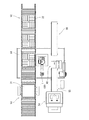
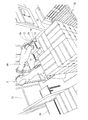
- FIG. 1 is a layout conceptual diagram of an example of a box unpacking system including a box unpacking device according to an embodiment of the present invention.
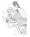
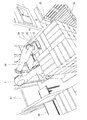
- FIG. 2 is a perspective view showing the robot and the depalletizing area.
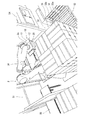
- FIG. 3 is a diagram showing a box position measuring operation which is the first half of the depalletizing operation.
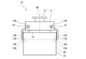
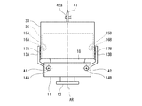
- FIG. 4 is a front view showing the configuration of the holding device.
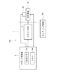
- FIG. 5 is a block diagram showing a configuration of a control system of the box unpacking device of FIG.
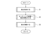
- FIG. 6 is a flow chart showing the outline of the box unpacking operation of the box unpacking device of FIG.
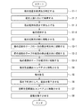
- FIG. 7 is a flowchart showing details of the box unpacking operation of the box unpacking device of FIG.
- FIG. 1 is a layout conceptual diagram of an example of a box unpacking system including a box unpacking device according to an embodiment of the present invention.
- FIG. 2 is a perspective view showing the robot and the depalletizing area.
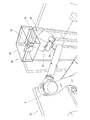
- FIG. 8A is a diagram showing a box picking operation which is the latter half of the depalletizing operation.
- FIG. 8B is a diagram showing a box picking operation which is the latter half of the depalletizing operation.
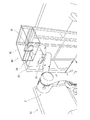
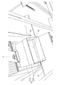
- FIG. 8C is a diagram showing a cardboard box cutting operation.
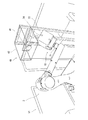
- FIG. 8D is a diagram showing a cardboard box cutting operation.
- FIG. 8E is a diagram showing a cardboard box cutting operation.
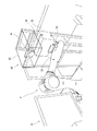
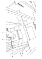
- FIG. 8F is a diagram showing a cardboard box cutting operation.
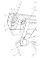
- FIG. 8G is a diagram showing a cardboard box cutting operation.
- FIG. 8H is a diagram showing a cardboard box cutting operation.
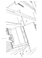
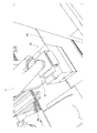
- FIG. 8I is a diagram showing a state inside the box during cutting of the cardboard box.
- FIG. 8J is a diagram showing a cardboard box cutting operation.
- FIG. 8I is a diagram showing a state inside the box during cutting of the cardboard box.
- FIG. 8K is a diagram showing a product (contained item) unloading operation.
- FIG. 8L is a diagram showing a product (contained item) unloading operation.
- FIG. 8M is a diagram showing a product (contained item) unloading operation.
- FIG. 8N is a diagram showing an empty box discharging operation.
- FIG. 8O is a diagram showing an empty box discharging operation.
- FIG. 9 is a diagram showing another mode of the depalletizing operation.
- FIG. 1 is an example of a layout conceptual diagram of a box unpacking system including a box unpacking device according to an embodiment of the present invention.
- FIG. 2 is a perspective view showing the robot and the depalletizing area.
- FIG. 3 is a diagram showing a box position measuring operation which is the first half of the depalletizing operation.
- FIG. 4 is a front view showing the configuration of the holding device. This box unpacking system is also the working environment of the box unpacking apparatus 100.
- the box unpacking system includes a robot 1, a cutting device 40, a depalletizing area 51, an actual pallet conveyor 52, a pallet magazine 53, a bag releasing machine 54, and a product unloading machine. It includes a conveyor 55 and an empty box discharge conveyor 56.
- the robot 1 and the cutting device 40 constitute a box unpacking device 100.
- the operation of the robot 1 is controlled by the robot controller 3 (FIG. 5), and the operation of the components of the box unpacking system other than the robot 1 is controlled by the system controller (not shown).
- the control of the operation of the robot 1 and the control of the box unpacking system are mutually linked.
- a pallet 31 (hereinafter, referred to as a pallet 31) on which a box assembly 32 formed by appropriately collecting corrugated cardboard boxes (hereinafter simply referred to as “boxes”) 33 is placed (arranged) on an actual pallet transfer conveyor 52.
- the pallet on which the box assembly 32 is placed is transported and stopped at the depalletizing area 51.
- the box 33 has a container (product) 36 stored therein, and is sealed (sealed) with a tape 34.
- the robot 1 picks up the box 33 from the box assembly 32, unpacks the box 33 using the cutting device 40, and drops the contents 36 on the product unloading conveyor 55.
- the product unloading conveyor 55 conveys the stored items 36 to the bag unpacking machine 54, and the bag unpacking machine 54 unpacks the bags of the stored items 36 and appropriately processes the stored items.
- the robot 1 drops the empty box 33 onto the empty box discharge conveyor 56.
- the empty box discharge conveyor 56 carries out the empty box 33.
- the empty pallet 31 is transferred to the pallet magazine 53 by the actual pallet transfer conveyor 52 and the next actual pallet 31 is moved to the depalletizing area. Stopped at 51. Empty pallets 31 are stacked in the pallet magazine 53.
- box unpacking device 100 Next, the box unpacking device 100 will be described in detail.
- the robot 1 has a robot hand including a holding device 10 that holds the packed box 33 on the wrist 2a, and it is sufficient that the box 33 held by the holding device 10 can be moved within a vertical plane.
- the robot 1 can push the box 33 held by the holding device 10 upward in the vertical plane to press the cutting blade 41 against the surface to be cut, and the box 33 can be cut in the vertical plane. This is because the surface to be cut can be cut open by moving the blade edge of 41 in the extending direction.
- opening the surface of the box 33 means that a cut line reaching the internal space is formed or a linear opening is formed in the surface of the box 33.
- the robot 1 may further be capable of changing the angle in the rotation direction in which the box 33 held by the holding device 10 is turned upside down. According to this configuration, since the lower surface of the box 33 held by the holding device 10 can be directed to the cutting blade 41, the lower surface of the box 33 can be cut open.
- the robot 1 can move the box 33 held by the holding device 10 in the vertical plane, and can change the angle in the rotation direction in which the box 33 held by the holding device 10 is vertically inverted. You can
- Examples of the robot 1 include a vertical articulated robot, a horizontal articulated robot, a delta robot, a parallel link robot, and a box unpacking robot.
- the robot 1 includes a robot body 2 and a robot controller 3 (see FIG. 5).
- the robot 1 is composed of, for example, a 6-axis vertical articulated robot, and the robot body 2 is composed of a vertical articulated robot arm. Since the vertical articulated robot is well known, its detailed description is omitted.
- a robot hand including the holding device 10 here, substantially composed of only the holding device 10) is attached.
- the box 33 may be any box as long as it can house (enclose) the contents 36 and can be cut open by the cutting blade 41.
- the form of the box 33 is not particularly limited.
- the box 33 is configured to have a bottom surface, a top surface that faces the bottom surface, and a side surface that connects the entire circumference of the bottom surface and the entire circumference of the top surface.
- the box 33 is a packed cardboard box.
- the shape of the box 33 is a rectangular parallelepiped.
- the box 33 is composed of a quadrangular prism-shaped main body 33a composed of four rectangular parallelepiped side walls, and flaps 33b formed at the upper and lower ends of the side walls of the main body 33a, respectively.
- the top wall and the bottom wall are formed by bending and appropriately combining the flaps 33b and closing both end surfaces of the rectangular columnar main body 33a.
- the walls at both ends of the rectangular columnar main body 33a are referred to as "end walls”.
- the end wall is sealed with an adhesive tape (hereinafter, simply referred to as “tape”) 34 so that the flap 33b does not open.
- tape adhesive tape
- the shape and number of flaps 33b and the manner of sealing with the tape 34 are various, but a general one is as follows.
- a pair of opposing short sides and a pair of long sides of the rectangular end surface of the main body portion 33a are respectively defined as bent portions, and a pair of rectangular short side flaps 33b extending from the pair of folded portions, respectively.
- the end wall is formed by a pair of long side flaps 33b.
- the pair of short side bent portions of the rectangular end surface are bent, and the pair of short side flaps 33b are extended along the end surface at intervals.
- the bent portions of the pair of long sides of the rectangular end surface are bent, and the leading edges of the pair of long side flaps 33b are butted against each other.
- the tape 34 attaches the pair of long side flaps 33b so as to cover the abutting portion and straddle the pair of long side flaps 33b. Then, the side edge of the flap 33b for the long side overlaps with the bent portion of the short side of the main body 33a.
- the tape 34 adheres the long side flap 33b and the side plate of the box 33 so as to cover the overlapping portion and to extend over the long side flap 33b and the short side bent portion of the main body 33a.
- the side edge of the flap 22 for the long side and the short side of the body portion 33a are bonded at two locations on the body portion 33a.
- the tape 34 has an H-shape (hereinafter, this tape sticking mode is referred to as “H-shaped tape sticking mode”).
- this tape sticking mode is referred to as “H-shaped tape sticking mode”.
- the tape 34 has an I-shape when the end wall is viewed from the front (hereinafter, the pasting mode of the tape 34 is referred to as “I-shaped tape pasting mode”).
- I-shaped tape sticking mode is exemplified.
- the unpacking operation described below can be applied to the H-shaped tape sticking mode in exactly the same manner.
- the end wall is composed of one flap 33b.
- the flap 33b has its edge overlapped with the bottom edge of the side wall of the main body 33a, covers the overlapped portion, and straddles the flap 33b and the side wall of the main body 33a.
- the side wall of the portion 33a is attached.
- box assembly 32 Referring to FIG. 3, the boxes 33 are stacked on the pallet 31 to form a box assembly 32.
- the boxes 33 may be regularly arranged. The reason why the regularity is required is that, in order for the robot 1 to hold the boxes 33 arranged on the pallet 31, the position of each box 33 on the pallet 31 needs to be specified.
- the box assembly 32 is composed of, for example, one or more steps that are laminated so that the entire peripheral surface is in the form of a square columnar surface.
- Each stage is composed of one or more boxes 33 arranged so as to form a geometric figure as a whole in a plan view.
- the geometric figure is a square.
- other geometric figures may be used.
- Each box 33 is arranged so that the top surface is the top surface.
- the cutting device 40 is installed near the robot 1.
- the cutting device 40 has a cutting blade 41 with the cutting edge facing downward.
- the cutting edge of the cutting blade 41 may be obliquely downward.
- the cutting blade 41 may have a cutting edge that faces downward or obliquely downward.
- the shape of the cutting blade 41 is not particularly limited, and examples thereof include a disk shape, a knife shape, and a chainsaw shape.
- the cutting blade 41 may be fixed or movable.
- the cutting blade 41 is arranged at a position where the robot 1 can move the holding device 10 under the cutting blade 41. With this arrangement, the robot 1 can press the box 33 held by the holding device 10 against the cutting blade 41 from below the cutting blade 41 to open the box 33.
- the cutting device 40 includes, for example, a disc-shaped cutting blade 41 and a support body 42.
- the support 42 is drawn transparent in FIG. 2 (and FIGS. 8D to 8H and J) for convenience of description.
- the support body 42 is supported at a required height by an appropriate support structure, and is formed in a frame body having an open lower end.
- the cutting blade 41 is rotatably attached to the support body 42 in a vertical plane via a horizontal rotation shaft 42a (see FIG. 8I).
- the lower end portion of the cutting blade 41 is exposed from the lower end of the support body 42.
- the cutting blade 41 is rotationally driven by, for example, a motor (not shown).
- the contents 36 are not particularly limited. Examples include products and mail items. Examples of products include bagged products (for example, foods, plastic bags filled with nuts, daily necessities), industrial materials, parts, and the like.
- the holding device 10 includes a main body portion 11, a mounting portion 12, a pair of gripping members 13A and 13B, a suction portion 18, and a three-dimensional position measuring device (box position detection device). Container 20).
- the three-dimensional position measuring device 20 is not shown. The three-dimensional position measuring device 20 will be described in detail later. Further, in FIG. 4, for convenience, the horizontal direction and the vertical direction of the drawing are defined as the horizontal direction and the vertical direction of the holding device 10, respectively.
- the main body 11 is formed in a frame body having an inverted U-shaped cross section as viewed in the left-right direction and extending in the left-right direction (see particularly FIG. 3).
- a cylindrical mounting portion 12 having a flange at the tip is provided upright.
- the central axis of the mounting portion 12 constitutes the reference axis line AR of the holding device 10.
- the holding device 10 is attached to the wrist 2a such that the reference axis line AR coincides with the axis line of the twist rotation of the wrist 2a of the robot body (robot arm) 2. Further, as will be described later, the holding device 10 is positioned by the robot main body 2 such that the main body portion 11 is above the corrugated cardboard box 33 and the reference axis line AR is substantially aligned with the central axis of the corrugated cardboard box 33.
- the holding device 10 is shown in a posture in which the reference axis line AR extends in the vertical direction (vertical direction).
- the base ends of the pair of gripping members 13A and 13B are attached to the main body 11 at a predetermined distance in a predetermined direction (left and right direction) perpendicular to the reference axis AR.
- the base end portions of the pair of gripping members 13A and 13B are rotatable about a pair of rotation axis lines A1 and A2 perpendicular (orthogonal) to the extending direction of the reference axis line AR and the predetermined direction. It is attached to 11.
- the portions of the main body portion 11 to which the base end portions of the pair of gripping members 13A and 13B are attached are equally spaced from the reference axis AR of the main body portion 11 in the predetermined direction.
- the pair of gripping members 13A and 13B are driven by a pneumatic control circuit (not shown).
- the pair of gripping members 13A and 13B are indicated by one reference numeral 13 for simplification in the drawings other than FIGS. 4 and 8I.
- the pair of gripping members 13A and 13B are, for example, in the direction or side (hereinafter referred to as inward or inward) in which the pair of gripping members 13A and 13B approach each other when viewed from the extending direction of the respective rotation axis lines A1 and A2. It is formed in a plate shape having a bent cross section.
- Inwardly protruding claws 15A and 15B are provided at the tips of the pair of gripping members 13A and 13B, respectively.
- friction members 17A and 17B are attached to portions of the inner surfaces of the pair of gripping members 13A and 13B on the tip side of the bent portions, respectively.
- the pair of friction members 17A and 17B may be members having a large friction coefficient, and examples of the pair of friction members 17A and 17B include members made of rubber, sponge, sandpaper and the like.
- the length and the degree of bending of the pair of gripping members 13A and 13B are in a state in which the main body 11 is located above the corrugated cardboard box 33 (more specifically, a state in which the suction portion 18 adsorbs the central portion of the upper surface of the corrugated cardboard box 33). ), For example, the pair of claws 15A and 15B bite into the upper portions of the left and right side walls of the cardboard box 33, respectively, and the pair of friction members 17A and 17B contact the upper portions of the left and right side walls of the cardboard box 33, respectively. It is set (designed).
- the length of the pair of gripping members 13A and 13B and the degree of bending may be such that the main body 11 is positioned above the corrugated board box 33.
- the suction portion 18 sucks the central portion of the upper surface of the corrugated cardboard box 33
- the pair of claws 15A and 15B bite into either part of the left and right side walls of the corrugated cardboard box 33, respectively
- the pair of friction members 17A and 17B may be set (designed) so as to abut on either part of the left and right side walls of the corrugated board box 33, respectively.
- the suction unit 18 is composed of, for example, a vacuum suction pad.
- the suction unit 18 is provided, for example, so that the central axis thereof coincides with the reference axis line AR.
- the suction unit 18 performs a suction / release operation by the pneumatic control circuit described above.
- the three-dimensional position measuring device 20 as a box position detector is provided on the side of the main body 11 of the holding device 10.
- the three-dimensional position measuring device 20 measures the three-dimensional position of the box 33.
- the three-dimensional position measuring device 20 is composed of, for example, a three-dimensional vision camera, an image sensor, an ultrasonic distance sensor, and the like.
- the three-dimensional position measuring device 20 is composed of a three-dimensional vision camera.
- FIG. 5 is a block diagram showing the configuration of the control system of the box unpacking device 100 of FIG.
- the robot controller 3 is composed of a single controller for centralized control or a plurality of controllers for distributed control.
- the robot controller 3 is composed of a single controller that performs centralized control here.
- the installation location of the robot controller 3 is not particularly limited.
- the robot controller 3 is installed, for example, at the base of the robot body 2 (see FIG. 2).
- the robot controller 30 includes, for example, a processor Pr and a memory Me.
- the robot controller 3 controls the operations of the robot body 2 and the holding device 10 by the processor Pr reading and executing a predetermined control program stored in the memory Me.
- the robot controller 3 is specifically configured by, for example, a microcontroller, MPU, FPGA (Field Programmable Gate Array), PLC (Programmable Logic Controller), logic circuit, and the like.
- the robot controller 3 controls the operation of the robot body 2 by controlling the motors that drive the respective joints of the robot body 2, and the holding device by controlling the pneumatic control circuit of the holding device 10. 10 operations are controlled. Further, the robot controller 3 specifies the three-dimensional position of the box 33 based on the measurement data of the three-dimensional position measuring device 20. Then, the robot controller controls the operations of the robot body 2 and the holding device 10 so as to hold the box 33 based on the specified three-dimensional position of the box 33, and according to the above-mentioned predetermined control program, the robot body. 2 and the holding device 10 are caused to perform an unpacking operation.
- the cutting device 40 is appropriately controlled by the system control device (not shown) described above.
- the robot controller 3 may control the operation of the cutting device 40.
- FIG. 6 is a flowchart showing an outline of the box unpacking operation of the box unpacking device of FIG.
- the operations of the robot 1 and the holding device 10 are performed under the control of the robot controller 3.
- the robot 1 holds the box 33 with the holding device 10 (step S1).
- the robot 1 moves the box 33 to the cutting device 40 (step S2).
- the robot 1 unpacks the box 33 using the cutting blade 41 of the cutting device 40 (step S3).
- FIGS. 2 to 4, FIG. 7, and FIGS. 8A to 8N This detailed operation is performed as follows, for example. Of course, the operation may be performed in other modes.
- the operation of the robot body 2 under a holding mode in which the wrist 2a is positioned above the box 33 and the surfaces (top surface and side surface) other than the bottom surface of the box 33 are held is illustrated. Moreover, the cutting blade 41 is rotating.
- the robot 1 has one box 33 whose top surface is exposed and is located at a predetermined position.
- the three-dimensional position measuring device 20 measures the three-dimensional position of the box 33.
- the box 33 to be measured is specified in advance by the above-described predetermined control program and its three-dimensional position is also specified.
- the actual three-dimensional position of the box 33 is the position error of the pallet 31 and the box set. Since an error is included due to an error in the arrangement of the box 33 when the body 32 is formed, the error is corrected to the measured three-dimensional position (step S1-1).
- the box 33 is held by the pair of holding members 13A and 13B of the holding device 10. Therefore, in order to accurately hold the box 33, the three-dimensional position of the box 33 is accurate. Is important.
- step S1-2 the robot 1 sucks the top surface of the designated box 33 by the suction unit 18 (see FIG. 4) (step S1-2).
- the robot 1 lifts the adsorbed box 33 to a predetermined gripping position (step S1-3).
- the robot 1 grips the upper part of the box with the pair of gripping members 13A and 13B (13) (step S1-4).
- the box 33 is firmly held by the robot 1 and the box 33 can be transported (moved).
- the robot 1 moves the held box 33 in front of the cutting blade 41 of the cutting device 40 (step S2). More specifically, when the robot 33 holds the box 33, the robot 1 changes the angle of the box 33 in the rotation direction to turn the box 33 upside down, thereby changing the posture of the box 33 so that the top surface of the box 33 faces obliquely upward. .. Due to this change in posture, the contents 36 (see FIG. 8I) in the box 33 are moved to the lower side of the box 33. As a result, a gap is formed in the upper part of the inner space of the box 33.
- the cutting blade 41 Since a gap is formed in the upper part of the internal space of the box 33, even if the cutting blade 41 moves relative to the box 33 while the blade tip is pierced into the box, the cutting blade 41 removes the contents in the box 33. It does not hurt. Then, the robot 1 positions one end of one short side of the box 33 (the right end in FIG. 8D) to the left of the lower end of the cutting blade 41.
- the robot 1 horizontally moves the box 33 along the extending surface of the cutting blade 41 to the right side in FIG. 8D.
- one side of the tape 34 on the bottom side of the box 33 is laterally cut (step S3-1).
- the tape corresponding to one short side of the box 33 is also cut.
- the above cutting operation is performed by moving the box 33 within a vertical plane including the extending surface of the cutting edge of the cutting blade 41.
- the robot 1 rotates the box 33 by 180 degrees around the central axis of the wrist 2a (reference axis AR of the holding device 10), and thereafter, in the same manner as step S3-1.
- the other side of the tape 34 on the bottom side of the box 33 is laterally cut (step S3-2).
- the tape corresponding to the other short side of the box 33 is also cut.
- the robot 1 rotates the box 33 by 90 degrees around the central axis of the wrist 2a and directs the box 33 directly upward, and one side of the box 33 (the right side in FIG. 8H). ) Is located on the left side of the lower end of the cutting blade 41.
- the robot 1 horizontally moves the box 33 along the extending surface of the cutting blade 41 to the right side in FIG. 8H.
- the contents 36 in the box 33 are moved to the lower side of the box 33, and a gap is formed in the upper part of the internal space of the box 33. It does not damage the contents inside.
- step S3-3 the portion located on the bottom surface of the tape 34 on the bottom side of the box 33 is vertically cut. Note that, also in the case of the H-shaped tape adhering mode, similarly to this, the portion located on the bottom surface of the tape 34 on the bottom side of the box 33 is cut in the vertical direction.
- the cutting operation in step S3-3 is also performed by moving the box 33 within the vertical plane including the extending surface of the cutting edge of the cutting blade 41.
- step S4 the robot 1 moves the box 33 onto the product unloading conveyor 55, which is a storage table.
- the robot 1 twists the box 33 so that the contents 36 are discharged from the box 33 onto the product unloading conveyor 55 while pushing away the flap 33b (step S5). .. in this case.
- the box 33 may be twisted so that it faces sideways, or may be twisted so that the box 33 is upright. Further, the posture of the box 33 may be changed in a mode other than twisting.
- the robot 1 moves the empty box 33 onto the empty box discharge conveyor 56 (step S7).
- the robot 1 releases the box 33 by releasing the suction by the suction unit 18 of the holding device 10 and releasing the pair of holding members 13. Then, the empty box 33 falls on the empty box discharge conveyor 56 (step S8). The dropped empty box 33 is carried out by the empty box discharge conveyor 56.
- the robot 1 may change the angle of the box 33 held by the holding device 10 in the rotation direction in which the box 33 is turned upside down so that the surface of the box 33 to be opened is oriented perpendicular to the cutting blade 41. It is possible to move the box 33 upward in the vertical plane so that the surface to be cut can be pressed against the cutting blade 41, and the box 33 can be moved in the extending direction of the cutting blade 41 in the vertical plane. By moving, the surface to be cut can be cut open.
- the box 33 can be unpacked in accordance with various sizes of the box 33 and various sealing forms.
- the surface to be cut out at the time of cutting is upward, the contents 36 in the box 33 are moved downward by their own weight, and the possibility that the contents 36 are damaged by the cutting blade 41 is reduced.
- FIG. 9 is a diagram showing another mode of the depalletizing operation.
- a plurality of boxes 33 are arranged in a row on the pallet 31 as a box assembly 32.
- the number of rows is not particularly limited. As such a case, for example, the box 33 is vertically long and the box assembly 32 becomes unstable when stacked.
- the box 33 at the front end in the box row of the box assembly 32 is a box located at a predetermined position.
- the robot body 2 moves the box 33 located at the front end of the box row to a surface other than the lower surface of the box 33 (here three Hold the sides (front, left, and right).
- the box 33 located at the predetermined position when the box 33 located at the predetermined position is arranged so as to be able to hold the side surface, the box 33 located at the predetermined position can be easily held and the box 33 can be held.
- the lower surface of can be cut open.
- Modification 2 is similar to the modification except for the following points.
- the robot body 2 holds the box 33 by the holding device 10 as in the first modification, and then opens the box 33 without turning the box 33 upside down. More specifically, the tape 34 on the top side of the box 33 is cut in steps S3-1 to S3-3 of the flowchart of FIG.
- the upper surface of the box 33 in the arranged state can be cut open.
- the unpacked box 33 can be turned upside down to drop the contained item 36 and take it out of the box 33.
- the box unpacking device 100 includes an operating device that operates the robot 1, and an operator uses the operating device.
- the box unpacking device 100 may be configured to unpack the box 33 by operating the robot 1.
- the box unpacking device 100 may be configured such that the operator operates the robot body 2 and the holding device 10 without using the control device.
- an operation signal is input to the robot controller 3 by operating the operation device, and the robot unpacking device 110 controls the operations of the robot body 2 and the holding device 10 in accordance with the operation signal. May be configured.
- the box 33 does not have to be sealed with the tape 34.
- the box 33 may be enclosed by engaging or adhering the flaps to each other.
- the box 33 may be sealed by mounting the end wall by an appropriate mounting means (coupling, fastening, etc.).
- the box holding unit includes the upper wall holding unit (suction unit 18) and the pair of side wall holding units (holding members 13A and 13B), but either one may be used.
- the case where the cardboard boxes 33 are stacked is illustrated, but the mounting form of the cardboard boxes 33 is not limited to this.
- a plurality of cardboard boxes may be stacked in one row.
- the upper wall holding portion (suction portion 18) may be omitted.
- the direction in which the holding device 10 holds the cardboard box 33 is not particularly limited.
- the holding device 10 may hold the cardboard box 33 from the side or the bottom.
- the holding device 10 may hold the cardboard box 33 with the main body portion 11 adjacent to the end wall of the cardboard box 33 opposite to the end wall to be cut open.
- the box holders (18, 13) may hold the cardboard box 33 by supporting a part of the cardboard box 33 other than the end wall to be cut open, for example, holding the ridges or corners of the cardboard box 33. May be.
- the suction portion 18 is illustrated as the upper wall holding portion, but the upper wall holding portion only needs to support and hold the upper wall of the cardboard box 33.
- the upper wall holding portion may include a claw that can bite into the upper wall and support the cardboard box 33.
- the side wall holding section is exemplified by the pair of gripping members 13A and 13B, but the side wall holding section is only required to support the side wall and hold the cardboard box 33.
- the side wall holding part may be configured to advance and retreat in the left-right direction to sandwich the pair of side walls.
- the gripping member 13 of the holding device 10 was driven by the pneumatic control circuit, but the power source of the gripping member 13 is not limited to this.
- the grip member 13 may be driven by a motor.
- the cutting device 40 may have a plurality of cutting blades 41.
- the three-dimensional position measuring device 20 may be omitted.
- the box unpacking device of the present invention is useful in the technical field of a device for unpacking a packed and sealed box and taking out the contents in the box.
Landscapes
- Engineering & Computer Science (AREA)
- Mechanical Engineering (AREA)
- Robotics (AREA)
- Life Sciences & Earth Sciences (AREA)
- Forests & Forestry (AREA)
- Human Computer Interaction (AREA)
- Control And Other Processes For Unpacking Of Materials (AREA)
- Manipulator (AREA)
Abstract
箱開梱装置は、ロボットと、カッティング装置と、を備えている。ロボットの手首にはロボットハンドが取り付けられている。ロボットハンドは梱包された箱を保持する保持装置を有している。カッティング装置は、刃先が下向き、又は、斜め下向きになった切断刃を有している。ロボットは、保持装置で保持した箱を、垂直平面内で移動させることができ、且つ、垂直平面内で角度変化させることができる。
Description
本発明は、荷詰めされて封緘された箱を開梱して、箱の中の収容物を取り出す装置及びそれを用いた方法に関する。
荷詰めされ封緘された段ボール箱を開梱して、箱の中の収容物を取り出すための、ロボットを含む装置が、特許文献1等で提案されている。
上述の特許文献1の装置では、梱包材切断部の刃物で段ボール箱に切れ目を入れる。しかしこの梱包材切断部は搬送経路中に設置されている。そのため所定の段ボール箱の大きさ、所定の封緘形態にしか対応できない。つまり、種々の箱の大きさや種々の封緘形態に対応することが困難である。
本発明は、このような状況に鑑みてなされたものであり、種々の箱の大きさや種々の封緘形態に対応することができる箱開梱装置及び箱開梱方法を提供することを目的とする。
本発明のある態様(aspect)に係る箱開梱装置は、ロボットと、カッティング装置と、を備え、前記ロボットの手首にはロボットハンドが取り付けられ、前記ロボットハンドは、梱包された箱を保持する保持装置を有し、前記カッティング装置は、刃先が下向き又は斜め下向きになった切断刃を有し、前記ロボットは、前記保持装置で保持した前記箱を、鉛直平面内で移動させることができる。
この構成によれば、ロボットが、保持装置で保持した箱を鉛直平面内で上方に移動させることによって、切り開くべき面に切断刃に押し当てることができ、且つ、箱を当該鉛直平面内で切断刃の刃先の延在方向に移動させることによって、当該切断すべき面を切り開くことができる。従って、種々の箱の大きさや種々の封緘形態に対応して、箱を開梱することができる。しかも、箱の面を切り開く際に当該面が上方を向いていることから、箱内の収容物が自重により下方に寄せられているので、収容物が切断刃によって損傷する可能性が低減される。
前記ロボットは、前記保持装置を有する前記ロボットハンドが取り付けられた手首を含むロボット本体と、前記ロボット本体及び前記保持装置の動作を制御するロボット制御器とを備え、前記ロボット制御器は、前記ロボット本体が、所定位置に位置する前記箱を前記保持装置によって保持し、且つ、前記保持装置で保持した前記箱を少なくとも鉛直平面内で移動させることによって、前記箱の上を向いた面を前記切断刃により切り開き(cut open)、それによって前記箱を開梱するよう、前記ロボット本体を制御するように構成されていてもよい。ここで、「箱の面を切り開く」とは、箱の面に、内部空間に達する切れ目(cut line)を入れる、又は、線状の開口を形成する、ことを意味する。
この構成によれば、ロボット本体が、自動又は手動で制御されて、種々の箱の大きさや種々の封緘形態に対応して、箱を開梱することできる。
前記制御器は、前記ロボット本体が、前記手首を前記箱の側方に位置させるようにして前記箱の上面以外の面を保持し、その後、前記箱を少なくとも鉛直平面内で移動させることによって、前記箱の上面を前記切断刃によって切り開き、それによって前記箱を開梱するよう、前記ロボット本体を制御するように構成されていてもよい。
この構成によれば、箱の上面を切り開くことができる。収容物に上下の方向性が存在しない場合は、開梱した箱を上下反転させることによって、収容物を落下させて箱から取り出すことができる。
前記ロボットは、さらに、前記保持装置で保持した前記箱を上下反転させる回転方向において角度変化させることができてもよい。
この構成によれば、保持装置で保持した箱の下面を切断刃に向けることができるので、箱の下面を切り開くことができる。
前記ロボットは、前記保持装置を有する前記ロボットハンドが取り付けられた手首を含むロボット本体と、前記ロボット本体及び前記保持装置の動作を制御するロボット制御器とを備え、前記ロボット制御器は、前記ロボット本体が、前記保持装置で保持した前記箱を、少なくとも、上下反転させる回転方向において角度変化させ、それにより上向き又は斜め上向きになった前記箱の面を前記切断刃により切り開くことによって前記箱を開梱するよう、前記ロボット本体を制御するように構成されていてもよい。
前記ロボット制御器は、前記ロボット本体が、前記手首を前記箱の上方に位置させるようにして前記箱の少なくとも上面を保持し、その後、保持した箱を上下反転させる回転方向において角度変化させ、その後、前記箱を少なくとも鉛直平面内で移動させることによって、前記角度変化により上向き又は斜め上向きになった前記箱の下面を前記切断刃によって切り開き、それによって前記箱を開梱するよう、前記ロボット本体を制御するように構成されていてもよい。
この構成によれば、所定位置に位置する箱が上面のみを保持することが可能なように配置されている場合(例えば、多数の箱が多段に積層されるとともに各段に複数の箱がマトリクス状に配置されていて、所定位置に位置する箱が最上段の箱である場合)に、所定位置に位置する箱を容易に保持して、当該箱の下面を切り開くことができる。
前記ロボット制御器は、前記ロボット本体が、前記手首を前記箱の側方に位置させるようにして前記箱の下面以外の面を保持し、その後、保持した箱を上下反転させる回転方向において角度変化させ、その後、前記箱を少なくとも鉛直平面内で移動させることによって、前記角度変化により上向き又は斜め上向きになった前記箱の下面を前記切断刃によって切り開き、それによって前記箱を開梱するよう、前記ロボット本体を制御するように構成されていてもよい。
この構成によれば、所定位置に位置する箱が側面を保持することが可能なように配置されている場合(例えば、多数の箱が一列に配置されていて、所定位置に位置する箱が前端の箱である場合)に、所定位置に位置する箱を容易に保持して、当該箱の下面を切り開くことができる。
前記ロボット制御器は、前記ロボット本体が、前記保持装置で保持した前記箱を開梱した後、前記切断刃により切り開かれた面を下方に向けることによって前記箱の収容物を落下させるよう、前記ロボット本体を制御するように構成されていてもよい。
この構成によれば、開梱した箱の収容物を、容易にロボットによって取り出すことができる。
前記箱が、底面と、前記底面に対向する天面と、前記底面の全周と前記天面の全周とを接続する側面と、を有し、前記箱は、前記天面が上面となるように前記所定位置に位置しており、前記ロボット制御器は、前記ロボット本体が、前記手首を前記箱の上方に位置させるようにして前記箱の底面以外の面を保持し、その後、保持した箱を上下反転させる回転方向において角度変化させ、その後、前記箱を少なくとも鉛直平面内で移動させることによって、前記角度変化により上向き又は斜め上向きになった前記箱の底面を前記切断刃によって切り開き、それによって前記箱を開梱し、且つ、その後、前記切断刃により切り開かれた底面を下方に向けることによって前記箱の収容物を落下させるよう、前記ロボット本体を制御するように構成されていてもよい。
この構成によれば、ロボットによって、底面を切り開いて箱を開梱し、開梱した箱を上下反転して、収容物を取り出すことができる。その結果、収容物に上下の方向性がある場合に、正規の方向で収容物を取り出すことができる。
前記箱がパレット上に箱集合体として載置されており、前記保持装置は、前記箱の位置を検知する箱位置検知器を備えており、前記ロボット制御器は、前記箱位置検知が検知する前記箱の位置に基づいて、前記パレット上に載置された前記箱集合体の前記所定位置に位置する前記箱を前記保持装置で保持するよう構成されていてもよい。
ロボットがプログラム制御される場合、検知対象の箱は、予め指定されていて、その位置も特定されている。しかし、箱の現実の位置は、パレットの位置誤差、箱集合体形成時における箱の配置誤差等に起因して、誤差を含む。この構成によれば、例えば、検知対象の箱の位置を、箱位置検知器で検知した位置に補正することにより、箱を正確に保持することができる。
前記カッティング装置の前記切断刃は、前記ロボットが前記ロボットハンドの前記保持装置を前記切断刃の下において移動させることが可能な位置に配置されていてもよい。
この構成によれば、ロボットが、保持装置で保持した箱を切断刃の下方から当該切断刃に押し当てて箱を切り開くことができる。
前記ロボットが垂直多関節ロボットであってもよい。
この構成によれば、ロボットが保持装置で保持した箱を任意の姿勢で切断刃に当てて箱を切り開くことができるので、容易に種々の箱の大きさや種々の封緘形態に対応して、箱を開梱することできる。
また、本発明の他の態様(aspect)に係る箱開梱方法は、ロボットと、カッティング装置と、を備え、前記ロボットの手首にはロボットハンドが取り付けられ、前記ロボットハンドは、梱包された箱を保持する保持装置を有し、前記カッティング装置は、刃先が下向き又は斜め下向きになった切断刃を有する箱開梱装置を用いた箱開梱方法であって、
前記ロボットによって、前記保持装置で保持した前記箱を、鉛直平面内で移動させる工程Aを含む。
前記ロボットによって、前記保持装置で保持した前記箱を、鉛直平面内で移動させる工程Aを含む。
この構成によれば、種々の箱の大きさや種々の封緘形態に対応して、箱を開梱することができる。しかも、箱の面を切り開く際に当該面が上方を向いていることから、箱内の収容物が自重により下方に寄せられているので、収容物が切断刃によって損傷する可能性が低減される。
本発明の箱開梱装置によれば、種々の箱の大きさや種々の封緘形態に対応して、箱の中の収容物を傷つけることなく箱を開梱して中の収容物を取り出すことができる。
以下、本発明の箱開梱装置の一実施形態を、図面を参照しながら説明する。なお、以下では全ての図面を通じて同一又は相当する要素には同一の参照符号を付して、その重複する説明を省略する。また、以下の図は本発明を説明するための図であるので、本発明と関係の無い要素が省略される場合、誇張等のために寸法が正確でない場合、複数の図面において互いに対応する要素が一致しない場合等がある。また、本発明は、以下の実施形態に限定されない。
(実施形態)
図1は、本発明の一実施形態の箱開梱装置を含む箱開梱システムのレイアウト構想図の一例である。図2は、ロボットとデパレタイズエリアを示す斜視図である。図3は、デパレタイズ動作のうちの前半である箱位置計測動作を示す図である。図4は、保持装置の構成を示す正面図である。この箱開梱システムは、箱開梱装置100の作業環境でもある。
図1は、本発明の一実施形態の箱開梱装置を含む箱開梱システムのレイアウト構想図の一例である。図2は、ロボットとデパレタイズエリアを示す斜視図である。図3は、デパレタイズ動作のうちの前半である箱位置計測動作を示す図である。図4は、保持装置の構成を示す正面図である。この箱開梱システムは、箱開梱装置100の作業環境でもある。
[構成]
{ハードウエアの構成}
図1乃至図4を参照すると、箱開梱システムは、ロボット1と、カッティング装置40と、デパレタイズエリア51と、実パレット搬送コンベア52と、パレットマガジン53と、解袋機54と、製品搬出コンベア55と、空箱排出コンベア56とを含む。ロボット1とカッティング装置40とが、箱開梱装置100を構成する。ロボット1の動作は、ロボット制御器3(図5)によって制御され、ロボット1以外の箱開梱システムの構成要素の動作は、システム制御装置(不図示)によって制御される。ロボット1の動作の制御と箱開梱システムの制御とは相互に連係して行われる。
{ハードウエアの構成}
図1乃至図4を参照すると、箱開梱システムは、ロボット1と、カッティング装置40と、デパレタイズエリア51と、実パレット搬送コンベア52と、パレットマガジン53と、解袋機54と、製品搬出コンベア55と、空箱排出コンベア56とを含む。ロボット1とカッティング装置40とが、箱開梱装置100を構成する。ロボット1の動作は、ロボット制御器3(図5)によって制御され、ロボット1以外の箱開梱システムの構成要素の動作は、システム制御装置(不図示)によって制御される。ロボット1の動作の制御と箱開梱システムの制御とは相互に連係して行われる。
この箱開梱システムでは、実パレット搬送コンベア52上を、段ボール箱(以下、単に「箱」という)33を適宜集合してなる箱集合体32が載置(配置)されたパレット31(以下、箱集合体32が載置されたパレットを「実パレット」という)が搬送され、デパレタイズエリア51で停止される。箱33は、内部に収容物(製品)36が収容されていて、テープ34で封緘(封止)されている。実パレット31が停止すると、ロボット1は、箱集合体32から箱33を取り上げて、カッティング装置40を利用して箱33を開梱し、収容物36を製品搬出コンベア55に落下させる。すると、製品搬出コンベア55が、収容物36を解袋機54に搬送し、解袋機54が収容物36の袋を解いて収容物を適宜処理する。ロボット1は、空箱33を、空箱排出コンベア56上に落下させる。すると、空箱排出コンベア56が、空箱33を搬出する。これらの一連の箱開梱動作が繰り返されて、パレット31上が空になると、実パレット搬送コンベア52によって、空のパレット31がパレットマガジン53に搬送されるとともに次の実パレット31がデパレタイズエリア51に停止される。パレットマガジン53では、空のパレット31が積み上げられる。
次に、箱開梱装置100について詳しく説明する。
<ロボット1>
ロボット1は、手首2aに、梱包された箱33を保持する保持装置10を含むロボットハンドを有していて、保持装置10で保持した箱33を、鉛直平面内で移動させることができればよい。ロボット1が、保持装置10で保持した箱33を鉛直平面内で上方に移動させることによって、切り開くべき面に切断刃41に押し当てることができ、且つ、箱33を当該鉛直平面内で切断刃41の刃先の延在方向に移動させることによって、当該切断すべき面を切り開くことができるからである。ここで、「箱33の面を切り開く」とは、箱33の面に、内部空間に達する切れ目(cut line)を入れる、又は、線状の開口を形成する、ことを意味する。ロボット1は、さらに、保持装置10で保持した箱33を上下反転させる回転方向において角度変化させることができてもよい。この構成によれば、保持装置10で保持した箱33の下面を切断刃41に向けることができるので、箱33の下面を切り開くことができる。
ロボット1は、手首2aに、梱包された箱33を保持する保持装置10を含むロボットハンドを有していて、保持装置10で保持した箱33を、鉛直平面内で移動させることができればよい。ロボット1が、保持装置10で保持した箱33を鉛直平面内で上方に移動させることによって、切り開くべき面に切断刃41に押し当てることができ、且つ、箱33を当該鉛直平面内で切断刃41の刃先の延在方向に移動させることによって、当該切断すべき面を切り開くことができるからである。ここで、「箱33の面を切り開く」とは、箱33の面に、内部空間に達する切れ目(cut line)を入れる、又は、線状の開口を形成する、ことを意味する。ロボット1は、さらに、保持装置10で保持した箱33を上下反転させる回転方向において角度変化させることができてもよい。この構成によれば、保持装置10で保持した箱33の下面を切断刃41に向けることができるので、箱33の下面を切り開くことができる。
本実施形態では、ロボット1は、保持装置10で保持した箱33を、鉛直平面内で移動させることができ、且つ、保持装置10で保持した箱33を上下反転させる回転方向において角度変化させることができる。
ロボット1として、垂直多関節ロボット、水平多関節ロボット、デルタロボット、パラレルリンクロボット、箱開梱専用のロボット等が例示される。
ロボット1は、ロボット本体2と、ロボット制御器3(図5参照)とを含む。
図3を参照すると、ロボット1は、例えば、6軸の垂直多関節ロボットで構成され、ロボット本体2は、垂直多関節のロボットアームで構成される。垂直多関節ロボットは周知であるのでその詳細な説明を省略する。ロボット本体2の手首2aには、保持装置10を備えるロボットハンド(ここでは、実質的に保持装置10のみで構成される)が装着されている。
<段ボール箱33>
箱33は、内部に収容物36を収容して封緘(封止)でき、且つ、切断刃41で切り開くことができるものであればよい。箱33の形態は特に限定されない。ここでは、箱33が、底面と、底面に対向する天面と、底面の全周と天面の全周とを接続する側面と、を有する形態に構成されている。具体的には、箱33は、荷詰めされた段ボール箱である。ここでは、例えば、箱33の形状は、直方体である。箱33は、直方体の4つの側壁からなる四角柱状の本体部33aと、本体部33aの各側壁の上端及び下端にそれぞれ形成されたフラップ33bとで構成される。フラップ33bを折り曲げるとともに適宜組み合わせて、四角柱状の本体部33aの両端面を閉鎖することによって、それぞれ、天壁及び底壁が形成される。なお、本実施形態では、箱33の上下の方向を特に区別しない場合には、四角柱状の本体部33aの両端の壁を「端壁」と呼ぶ。端壁は、フラップ33bが開くことがないように、粘着テープ(以下、単に「テープ」という)34によって封緘される。箱33の端壁の形態により、フラップ33bの形状や枚数や、テープ34による封緘態様は種々であるが、一般的なものを説明すると次のとおりである。
箱33は、内部に収容物36を収容して封緘(封止)でき、且つ、切断刃41で切り開くことができるものであればよい。箱33の形態は特に限定されない。ここでは、箱33が、底面と、底面に対向する天面と、底面の全周と天面の全周とを接続する側面と、を有する形態に構成されている。具体的には、箱33は、荷詰めされた段ボール箱である。ここでは、例えば、箱33の形状は、直方体である。箱33は、直方体の4つの側壁からなる四角柱状の本体部33aと、本体部33aの各側壁の上端及び下端にそれぞれ形成されたフラップ33bとで構成される。フラップ33bを折り曲げるとともに適宜組み合わせて、四角柱状の本体部33aの両端面を閉鎖することによって、それぞれ、天壁及び底壁が形成される。なお、本実施形態では、箱33の上下の方向を特に区別しない場合には、四角柱状の本体部33aの両端の壁を「端壁」と呼ぶ。端壁は、フラップ33bが開くことがないように、粘着テープ(以下、単に「テープ」という)34によって封緘される。箱33の端壁の形態により、フラップ33bの形状や枚数や、テープ34による封緘態様は種々であるが、一般的なものを説明すると次のとおりである。
例えば、本体部33aの矩形の端面の一対の対向する短辺及び一対の長辺を、それぞれ折り曲げ部とし、各一対の折り曲げ部からそれぞれ延びるそれぞれ同形状の矩形の一対の短辺用のフラップ33b及び一対の長辺用のフラップ33bによって端壁が形成されるものがある。矩形の端面の一対の短辺の折り曲げ部が折り曲げられて、一対の短辺用のフラップ33bが間隔を置いて端面に沿って延在させられる。次いで、矩形の端面の一対の長辺の折り曲げ部が折り曲げられて、一対の長辺用のフラップ33bの先縁同士が突き合わされる。そしてその突き合せ部を覆い、且つ、一対の長辺用のフラップ33bに跨るようにしてテープ34が一対の長辺用のフラップ33bを貼り合わせる。そうすると、長辺用のフラップ33bの側縁が本体部33aの短辺の折り曲げ部に重なる。その重なり部を覆い、且つ、長辺用のフラップ33bと本体部33aの短辺の折り曲げ部とに跨るようにして、テープ34が長辺用のフラップ33bと箱33の側板とを貼り合わせる。通常、長辺用のフラップ22の側縁と本体部33aの短辺との貼り合わせは本体部33aの2箇所においてなされる。その結果、端壁を正面視するとテープ34がH字形状をなす(以下、このテープの貼着態様を「H字状テープ貼着態様」という)。なお、長辺用のフラップ22の側縁と本体部33aの短辺との貼り合わせが省略される態様がある。この場合、端壁を正面視するとテープ34がI字形状をなす(以下、このテープ34の貼着態様を「I字状テープ貼着態様」という)。本実施形態では、このI字状テープ貼着態様が例示される。但し、H字状テープ貼着態様に対しても、以下に説明する箱開梱動作が、全く同様に適用され得る。
また別の態様として次のようものもある。端壁は1枚のフラップ33bによって構成されている。フラップ33bはその縁が本体部33aの側壁の底縁に重なるようにされ、その重なり部を覆い、且つ、フラップ33bと本体部33aの側壁とに跨るようにして、テープ34がフラップ33bと本体部33aの側壁とを貼り合わせる。
<箱集合体32>
図3を参照すると、箱33は、パレット31上に箱集合体32を形成するように積み上げられる。箱集合体32は、箱33が規則的に配置されておればよい。規則性が要求される理由は、ロボット1がパレット31上に配置された箱33を保持するためには、各箱33のパレット31上における位置が特定されている必要があるからである。
図3を参照すると、箱33は、パレット31上に箱集合体32を形成するように積み上げられる。箱集合体32は、箱33が規則的に配置されておればよい。規則性が要求される理由は、ロボット1がパレット31上に配置された箱33を保持するためには、各箱33のパレット31上における位置が特定されている必要があるからである。
具体的には、箱集合体32は、例えば、全体として周面が面一の四角柱状になるように積層された1以上の段で構成される。各段は、平面視において、全体として幾何学図形を成すように並べられた1以上の箱33で構成される。ここでは、幾何学図形が正方形である。もちろん、他の幾何学図形であっても構わない。各箱33は、天面が上面となるように配置される。
<カッティング装置40>
図2を参照すると、カッティング装置40はロボット1の近傍に設置されている。カッティング装置40は、刃先が下方を向いた切断刃41を有する。なお、切断刃41の刃先は斜め下向きであってもよい。切断刃41は、下方又は斜め下方を向いた刃先を有するものであればよい。切断刃41の形状は、特に限定されず、円板状、ナイフ状、チェーンソー状等が例示される。切断刃41は、固定されていてもよく、移動可能であってもよい。
図2を参照すると、カッティング装置40はロボット1の近傍に設置されている。カッティング装置40は、刃先が下方を向いた切断刃41を有する。なお、切断刃41の刃先は斜め下向きであってもよい。切断刃41は、下方又は斜め下方を向いた刃先を有するものであればよい。切断刃41の形状は、特に限定されず、円板状、ナイフ状、チェーンソー状等が例示される。切断刃41は、固定されていてもよく、移動可能であってもよい。
切断刃41は、ロボット1が、保持装置10を切断刃41の下において移動させることが可能な位置に配置されている。このように配置されていれば、ロボット1が、保持装置10で保持した箱33を切断刃41の下方から当該切断刃41に押し当てて箱33を切り開くことができるからである。
具体的には、カッティング装置40は、例えば、円板状の切断刃41と支持体42とを備える。支持体42は、図2(及び図8D~8H、及びJ)において、説明の便宜上、透明に描かれている。支持体42は、適宜な支持構造によって所要の高さに支持されており、且つ、下端が開放された枠体に形成されている。そして、切断刃41が、水平な回転軸42a(図8I参照)を介して、鉛直平面内で回転可能に支持体42に取り付けられている。切断刃41の下端部は、支持体42の下端から露出している。切断刃41は、例えば、モータ(不図示)によって回転駆動される。
<収容物(製品)36>
収容物36(図4参照)は、特に限定されない。製品、郵便物等が例示される。製品として、袋詰めされた製品(例えば、食品、ナッツが詰まったビニール袋、日用品)、工業材料、部品等が例示される。
収容物36(図4参照)は、特に限定されない。製品、郵便物等が例示される。製品として、袋詰めされた製品(例えば、食品、ナッツが詰まったビニール袋、日用品)、工業材料、部品等が例示される。
<保持装置10>
図3及び図4を参照すると、保持装置10は、ここでは、本体部11と、取付部12と、一対の把持部材13A,13Bと、吸着部18と、3次元位置計測器(箱位置検知器)20と、を備える。なお、図4では、3次元位置計測器20の図示を省略している。3次元位置計測器20については、後で詳しく説明する。また、図4では、便宜上、図の左右方向及び上下方向を、それぞれ、保持装置10の左右方向及び上下方向と定義する。
図3及び図4を参照すると、保持装置10は、ここでは、本体部11と、取付部12と、一対の把持部材13A,13Bと、吸着部18と、3次元位置計測器(箱位置検知器)20と、を備える。なお、図4では、3次元位置計測器20の図示を省略している。3次元位置計測器20については、後で詳しく説明する。また、図4では、便宜上、図の左右方向及び上下方向を、それぞれ、保持装置10の左右方向及び上下方向と定義する。
本体部11は、左右方向から見て、逆U字状の断面を有し左右方向に延在する枠体に形成されている(特に図3参照)。
この本体部11の中央部に、先端にフランジを有する円筒状の取付部12が上方向に立設されている。取付部12の中心軸が保持装置10の基準軸線ARを構成している。保持装置10は、基準軸線ARがロボット本体(ロボットアーム)2の手首2aの捻り回転の軸線と一致するように当該手首2aに装着される。また、保持装置10は、後述するように、ロボット本体2によって、本体部11が段ボール箱33の上方に、基準軸線ARが段ボール箱33の中心軸に略一致するようにして、位置させられる。
図4では、保持装置10が、基準軸線ARが上下方向(鉛直方向)に延在する姿勢で示されている。
一対の把持部材13A,13Bは、それぞれの基端部が、基準軸線ARに垂直な所定の方向(ここでは左右方向)において所定距離だけ離隔して本体部11に取り付けられている。一対の把持部材13A,13Bのそれぞれの基端部は、基準軸線ARの延在方向及び上記所定方向に垂直な(直交する)一対の回動軸線A1,A2の周りに回動可能に本体部11に取り付けられている。この一対の把持部材13A,13Bの基端部がそれぞれ取り付けられた本体部11の部位は、上記所定方向において、本体部11の基準軸線ARから互いに等しい距離離れている。一対の把持部材13A,13Bは、空圧制御回路(不図示)によって、駆動される。一対の把持部材13A,13Bは、図4及び図8I以外の図においては、簡略化のために、1つの参照符号13で示す。
一対の把持部材13A,13Bは、例えば、それぞれの回動軸線A1,A2の延在方向から見て、一対の把持部材13A,13Bが互いに接近する方向又は側(以下、内方又は内側という)に屈曲された断面形状を有する板状に形成されている。
一対の把持部材13A,13Bの先端には、それぞれ、内方に突出する爪15A,15Bが設けられている。また、一対の把持部材13A,13Bの内側の面の屈曲部より先端側の部分には、それぞれ、摩擦部材17A,17Bが取り付けられている。一対の摩擦部材17A,17Bは、摩擦係数の大きい部材であればよく、一対の摩擦部材17A,17Bとして、ゴム、スポンジ、サンドペーパー等から成る部材が例示される。
一対の把持部材13A,13Bの長さ及び屈曲の程度は、本体部11が段ボール箱33の上方に位置した状態(より詳しくは、吸着部18が段ボール箱33の上面の中央部を吸着した状態)において、例えば、一対の爪15A、15Bがそれぞれ段ボール箱33の左右の側壁の上部に食い込み、且つ、一対の摩擦部材17A,17Bがそれぞれ段ボール箱33の左右の側壁の上部に当接するように設定(設計)される。
但し、収容物36の状態によっては(例えば、収容物36が少ない場合等には)、一対の把持部材13A,13Bの長さ及び屈曲の程度は、本体部11が段ボール箱33の上方に位置した状態(より詳しくは、吸着部18が段ボール箱33の上面の中央部を吸着した状態)において、一対の爪15A、15Bがそれぞれ段ボール箱33の左右の側壁のいずれかの部分に食い込み、且つ、一対の摩擦部材17A,17Bがそれぞれ段ボール箱33の左右の側壁のいずれかの部分に当接するように設定(設計)されてもよい。
本体部11の下面には、吸着部18が設けられている。吸着部18は、例えば、真空吸着パッドで構成される。吸着部18は、例えば、中心軸が基準軸線ARに一致するように設けられる。吸着部18は、上述の空圧制御回路によって吸着/解放動作を行う。
<3次元位置計測器20>
図3に示すように、箱位置検知器としての3次元位置計測器20は、保持装置10の本体部11の側部に設けられる。3次元位置計測器20は、箱33の3次元位置を計測する。3次元位置計測器20は、例えば、3次元ビジョンカメラ、画像センサ、超音波距離センサ等で構成される。ここでは、3次元位置計測器20は、3次元ビジョンカメラで構成される。
図3に示すように、箱位置検知器としての3次元位置計測器20は、保持装置10の本体部11の側部に設けられる。3次元位置計測器20は、箱33の3次元位置を計測する。3次元位置計測器20は、例えば、3次元ビジョンカメラ、画像センサ、超音波距離センサ等で構成される。ここでは、3次元位置計測器20は、3次元ビジョンカメラで構成される。
{制御系統の構成}
図5は、図1の箱開梱装置100の制御系統の構成を示すブロック図である。
図5は、図1の箱開梱装置100の制御系統の構成を示すブロック図である。
図5を参照すると、ロボット制御器3は、集中制御を行う単独の制御器又は分散制御をする複数の制御器で構成される。ロボット制御器3は、ここでは、集中制御を行う単独の制御器で構成される。ロボット制御器3の設置場所は特に限定されない。ロボット制御器3は、例えば、ロボット本体2の基部(図2参照)に設置される。ロボット制御器30は、例えば、プロセッサPrとメモリMeとを備える。ロボット制御器3は、メモリMeに格納された所定の制御プログラムをプロセッサPrが読み出して実行することにより、ロボット本体2及び保持装置10の動作を制御する。ロボット制御器3は、具体的には、例えば、マイクロコントローラ、MPU、FPGA(Field Programmable Gate Array)、PLC(Programmable Logic Controller)、論理回路等で構成される。
具体的には、ロボット制御器3は、ロボット本体2の各関節を駆動するモータを制御することによってロボット本体2の動作を制御し、保持装置10の空圧制御回路を制御することによって保持装置10の動作を制御する。また、ロボット制御器3は、3次元位置計測器20の計測データに基づいて、箱33の3次元位置を特定する。そして、ロボット制御器は、この特定した箱33の3次元位置に基づいて箱33を保持するようロボット本体2及び保持装置10の動作を制御し、且つ、上述の所定の制御プログラムに従って、ロボット本体2及び保持装置10に、箱開梱動作を行わせる。
カッティング装置40は、上述のシステム制御装置(不図示)によって、適宜、制御される。なお、ロボット制御器3がカッティング装置40の動作を制御してもよい。
[動作]
次に、以上のように構成された箱開梱装置100の動作を説明する。まず、図2、図3、及び図6を用いて、箱開梱装置100の動作の概容を説明する。
次に、以上のように構成された箱開梱装置100の動作を説明する。まず、図2、図3、及び図6を用いて、箱開梱装置100の動作の概容を説明する。
図6は、図1の箱開梱装置の箱開梱動作の概容を示すフローチャートである。ロボット1及び保持装置10の動作は、ロボット制御器3の制御によって遂行される。
図2、図3、及び図6を参照すると、ロボット1は、保持装置10で箱33を保持する(ステップS1)。
次いで、ロボット1は、箱33をカッティング装置40へ移動させる(ステップS2)。
次いで、ロボット1は、カッティング装置40の切断刃41を利用して箱33を開梱する(ステップS3)。
次に、図2~4、図7、図8A~8Nを用いて、箱開梱装置100の動作を詳細に説明する。この詳細な動作は、例えば、以下のように遂行される。もちろん、これ以外の態様の動作で遂行されてもよい。以下では、ロボット本体2が、手首2aを箱33の上方に位置させるようにして箱33の底面以外の面(上面及び側面)を保持する保持形態の下での動作が例示される。また、切断刃41は、回転している。
まず、図3に示すように、ロボット1は、パレット31上の箱集合体32を構成する複数の箱33のうちの、天面が露出していて所定位置に位置する一つの箱33について、3次元位置計測器20で箱33の3次元位置を計測する。この計測対象の箱33は、上述の所定の制御プログラムにおいて予め指定されていて、その3次元位置も特定されているが、箱33の現実の3次元位置は、パレット31の位置誤差、箱集合体32の形成時における箱33の配置誤差等に起因して、誤差を含むので、これを計測した3次元位置に補正する(ステップS1-1)。特に、箱開梱装置100では、保持装置10の一対の把持部材13A,13Bによって箱33を把持することから、箱33を正確に把持するためには、箱33の3次元位置が正確であることが重要であるからである。
次いで、図8Aに示すように、ロボット1は、指定された箱33の天面を吸着部18(図4参照)で吸着する(ステップS1-2)。
次いで、図8Bに示すように、ロボット1は吸着した箱33を、所定の把持位置まで持ち上げる(ステップS1-3)。
次いで、図8Cに示すように、ロボット1は、一対の把持部材13A,13B(13)によって箱の上部を把持する(ステップS1-4)。これにより、箱33が、しっかりとロボット1に保持され、箱33を搬送する(移動させる)ことが可能になる。
次いで、図8Dに示すように、ロボット1は、保持した箱33をカッティング装置40の切断刃41の前に移動させる(ステップS2)。詳しく説明すると、ロボット1は、箱を33保持すると、箱33を上下反転させる回転方向において角度変化させることによって、保持した箱33の天面が斜め上を向くように箱33の姿勢を変化させる。この姿勢変化によって、箱33内の収容物36(図8I参照)が箱33の下方へ寄せられる。このことによって箱33の内部空間の上部に隙間が形成される。箱33の内部空間の上部には隙間が形成されているので、刃先が箱に突き刺さったまま切断刃41が箱33に対して相対移動しても、切断刃41が箱33内の収容物を傷つけることはない。そして、ロボット1は、箱33の一方の短辺の一端(図8Dにおける右端)を切断刃41の下端部の左側に位置させる。
次いで、ロボット1は、箱33を、切断刃41の延在面に沿って、図8Dの右側に水平に移動させる。
これにより、図8Fに示すように、箱33の底側のテープ34の一方の側が横方向に切断される(ステップS3-1)。なお、H字状テープ貼着態様の場合、箱33の一方の短辺に対応するテープも切断される。また、以上の切断動作は、箱33を、切断刃41の刃先の延在面を含む鉛直平面内で移動させることによって遂行される。
次に、図8Gに示すように、ロボット1は、手首2aの中心軸(保持装置10の基準軸線AR)の周りに箱33を180度回転させ、その後、ステップS3-1と同様にして、箱33の底側のテープ34の他方の側を横方向に切断する(ステップS3-2)。なお、H字状テープ貼着態様の場合、箱33の他方の短辺に対応するテープも切断される。
次いで、図8Hに示すように、ロボット1は、手首2aの中心軸の周りに箱33を90度回転させるとともに箱33を真上に向け、且つ、箱33の一方の側(図8Hにおける右側)の短辺の中央を切断刃41の下端部の左側に位置させる。
次いで、ロボット1は、箱33を、切断刃41の延在面に沿って、図8Hの右側に水平に移動させる。この際、図8Iに示すように、箱33内の収容物36が箱33の下方へ寄せられていて、箱33の内部空間の上部に隙間が形成されているので、切断刃41が箱33内の収容物を傷つけることはない。
これにより、図8Jに示すように、箱33の底側のテープ34の底面に位置する部分が縦方向に切断される(ステップS3-3)。なお、H字状テープ貼着態様の場合も、これと同様に、箱33の底側のテープ34の底面に位置する部分が縦方向に切断される。また、このステップS3-3における切断動作も、箱33を、切断刃41の刃先の延在面を含む鉛直平面内で移動させることによって遂行される。
かくして、フラップ33bに貼着された全てのテープ34が切断されることによって、箱33の底壁の封緘状態が解除される。
次いで、ロボット1は、箱33を、収容物台である製品搬出コンベア55の上に移動させる(ステップS4)。
次いで、図8K及び図8Lに示すように、ロボット1は、フラップ33bを押しのけながら収容物36が箱33から製品搬出コンベア55上に排出されるように、箱33を捩じる(ステップS5)。この場合。箱33が横向きになるように捩じってもよいし、箱33が正立するように捩じってもよい。また、捩じる以外の態様で箱33の姿勢を変化させてもよい。
これにより、図8Mに示すように、箱33の中に収容されていた収容物36が全て製品搬出コンベア55上に落下して排出される(ステップS6)。
次いで、図8Nに示すように、ロボット1は、空箱33を空箱排出コンベア56の上に移動させる(ステップS7)。
次いで、図8Oに示すように、ロボット1は、保持装置10の吸着部18による吸着を解除するとともに一対の把持部材13による把持を解除することによって、箱33を解放する。すると、空箱33は空箱排出コンベア56上に落下する(ステップS8)。落下した空箱33は空箱排出コンベア56によって搬出される。
そして、ロボット1は、以降、上述の動作を繰り返す。
このような実施形態によれば、ロボット1が、保持装置10で保持した箱33を、上下反転させる回転方向において角度変化させて当該箱33の切り開くべき面を切断刃41に垂直に向けることができ、当該箱33を鉛直平面内で上方に移動させることによって、当該切り開くべき面を切断刃41に押し当てることができ、且つ、当該箱33を鉛直平面内で切断刃41の延在方向に移動させることによって、当該切り開くべき面を切り開くことができる。
従って、種々の箱33の大きさや種々の封緘形態に対応して、箱33を開梱することができる。しかも、切り開く際に切り開くべき面が上を向いていることから、箱33内の収容物36が自重により下方に寄せられているので、収容物36が切断刃41によって損傷する可能性が低減される。
{変形例1}
図9は、デパレタイズ動作の他の態様を示す図である。図9を参照すると、本実施形態の変形例1では、パレット31上に、箱集合体32として、複数の箱33が、列状に配置されている。列の数は、特に限定されない。このような場合として、例えば、箱33が縦長で、積み上げると箱集合体32が不安定になる場合が挙げられる。
図9は、デパレタイズ動作の他の態様を示す図である。図9を参照すると、本実施形態の変形例1では、パレット31上に、箱集合体32として、複数の箱33が、列状に配置されている。列の数は、特に限定されない。このような場合として、例えば、箱33が縦長で、積み上げると箱集合体32が不安定になる場合が挙げられる。
本変形例では、この箱集合体32の箱列における前端の箱33が所定位置に位置する箱である。ロボット本体2は、各時点において、この箱列の前端に位置する箱33を、手首2aを箱33の前方(側方)に位置させるようにして箱33の下面以外の面(ここでは3つの側面(前面、左側面、及び右側面))を保持する。
これ以外の点は、上記実施形態と全く同じである。
この変形例1によれば、所定位置に位置する箱33が側面を保持することが可能なように配置されている場合に、所定位置に位置する箱33を容易に保持して、当該箱33の下面を切り開くことができる。
{変形例2}
変形例2は、以下の点以外は変形例と同様である。
変形例2は、以下の点以外は変形例と同様である。
本変形例2では、ロボット本体2が、変形例1と同様に保持装置10で箱33を保持した後、箱33を上下反転させないで、箱33を開梱する。詳しく説明すると、図7のフローチャートのステップS3-1~S3-3において、箱33の天側のテープ34が切断される。
この変形例2によれば、箱33の配置状態における上面を切り開くことができる。収容物36に上下の方向性が存在しない場合は、さらに開梱した箱33を上下反転させることによって、収容物36を落下させて箱33から取り出すことができる。
(その他の実施形態)
上記実施形態並びに変形例1及び変形例2(以下、単に「上記実施形態」という)において、箱開梱装置100がロボット1を操作する操作器を備えていて、操作者が操作器を用いてロボット1を操作することによって箱33を開梱するように箱開梱装置100が構成されていてもよい。この場合、例えば、操作者が制御装置を介さずにロボット本体2及び保持装置10を操作するように、箱開梱装置100を構成してもよい。また、例えば、操作器の操作により操作信号がロボット制御器3に入力され、ロボット制御器3が操作信号に応じてロボット本体2及び保持装置10の動作を制御するように、箱開梱装置110を構成してもよい。
上記実施形態並びに変形例1及び変形例2(以下、単に「上記実施形態」という)において、箱開梱装置100がロボット1を操作する操作器を備えていて、操作者が操作器を用いてロボット1を操作することによって箱33を開梱するように箱開梱装置100が構成されていてもよい。この場合、例えば、操作者が制御装置を介さずにロボット本体2及び保持装置10を操作するように、箱開梱装置100を構成してもよい。また、例えば、操作器の操作により操作信号がロボット制御器3に入力され、ロボット制御器3が操作信号に応じてロボット本体2及び保持装置10の動作を制御するように、箱開梱装置110を構成してもよい。
上記実施形態において、箱33がテープ34で封緘されていなくてもよい。例えば、箱33が、フラップを相互に係合させたり接着させたりすることによって、封緘されていてもよい。また、箱33が、端壁を適宜な装着手段(篏合、締結等)で装着されることによって、封緘されていてもよい。
上記実施形態では、箱保持部が上壁保持部(吸着部18)及び一対の側壁保持部(把持部材13A,13B)を備えるが、いずれか一方でもよい。
また、上記実施形態では、段ボール箱33が段積される場合を例示したが、段ボール箱33の載置形態はこれには限定されない。例えば、段ボール箱が1列に複数段積まれていてもよい。このような場合、上壁保持部(吸着部18)を省略してもよい。
また、保持装置10が段ボール箱33を保持する方向は、特に限定されない。例えば、段ボール箱33が天壁を横向き又は下向きにして載置されている場合、保持装置10は、段ボール箱33を側方又は下方から保持すればよい。要するに、保持装置10は、段ボール箱33の切り開くべき端壁と反対側の端壁に本体部11を隣接させて段ボール箱33を保持すればよい。
また、箱保持部(18、13)は、段ボール箱33の切り開くべき端壁以外の部分を支持して段ボール箱33を保持すればよく、例えば、段ボール箱33の稜部又は角部を保持してもよい。
上記実施形態では、上壁保持部として吸着部18を例示したが、上壁保持部は、段ボール箱33の上壁を支持して保持できればよい。例えば、上壁保持部が、上壁に食い込んで段ボール箱33を支持できるような爪を備えていてもよい。
上記実施形態では、側壁保持部が一対の把持部材13A,13Bで構成される形態を例示したが、側壁保持部は、側壁を支持して段ボール箱33を保持できればよい。例えば、側壁保持部が左右方向に進退して一対の側壁を挟持するように構成されてもよい。
また、上記実施形態では、保持装置10の把持部材13が空圧制御回路で駆動されたが、当該把持部材13の動力源はこれには限定されない。例えば、当該把持部材13がモータによって駆動されてもよい。
また、上記実施形態において、カッティング装置40が、複数の切断刃41を有していてもよい。
また、上記実施形態において、3次元位置計測器20を省略してもよい。
上記説明から、当業者にとっては、多くの改良や他の実施形態が明らかである。従って、上記説明は、例示としてのみ解釈されるべきである。
本発明の箱開梱装置は、荷詰めされて封緘された箱を開梱して、箱の中の収容物を取り出す装置の技術分野において有用である。
1 ロボット
2 ロボット本体
2a 手首
3 ロボット制御器
10 保持装置
11 本体部
12 取付部
13,13A,13B 把持部材
15A,15B 爪
17A,17B 摩擦部材
18 吸着部
20 3次元位置計測器(箱位置検知器)
31 パレット
32 箱集合体
33 段ボール箱(箱)
33a 本体部
33b フラップ
34 粘着テープ(テープ)
36 収容物
40 カッティング装置
41 切断刃
42 支持体
51 デパレタイズエリア
52 実パレット搬送コンベア
53 パレットマガジン
54 解袋機
55 製品搬出コンベア
56 空箱排出コンベア
100 箱開梱装置
Pr プロセッサ
Me メモリ
Claims (24)
- ロボットと、カッティング装置と、を備え、
前記ロボットの手首にはロボットハンドが取り付けられ、
前記ロボットハンドは、梱包された箱を保持する保持装置を有し、
前記カッティング装置は、刃先が下向き又は斜め下向きになった切断刃を有し、
前記ロボットは、前記保持装置で保持した前記箱を、鉛直平面内で移動させることができる、箱開梱装置。 - 前記ロボットは、前記保持装置を有する前記ロボットハンドが取り付けられた手首を含むロボット本体と、前記ロボット本体及び前記保持装置の動作を制御するロボット制御器とを備え、
前記ロボット制御器は、前記ロボット本体が、所定位置に位置する前記箱を前記保持装置によって保持し、且つ、前記保持装置で保持した前記箱を少なくとも鉛直平面内で移動させることによって、前記箱の上を向いた面を前記切断刃により切り開き、それによって前記箱を開梱するよう、前記ロボット本体を制御するように構成されている、請求項1に記載の箱開梱装置。 - 前記制御器は、前記ロボット本体が、前記手首を前記箱の側方に位置させるようにして前記箱の上面以外の面を保持し、その後、前記箱を少なくとも鉛直平面内で移動させることによって、前記箱の上面を前記切断刃によって切り開き、それによって前記箱を開梱するよう、前記ロボット本体を制御するように構成されている、請求項2に記載の箱開梱装置。
- 前記ロボットは、さらに、前記保持装置で保持した前記箱を上下反転させる回転方向において角度変化させることができる、請求項1に記載の箱開梱装置。
- 前記ロボットは、前記保持装置を有する前記ロボットハンドが取り付けられた手首を含むロボット本体と、前記ロボット本体及び前記保持装置の動作を制御するロボット制御器とを備え、
前記ロボット制御器は、前記ロボット本体が、前記保持装置で保持した前記箱を、少なくとも、上下反転させる回転方向において角度変化させ、それにより上向き又は斜め上向きになった前記箱の面を前記切断刃により切り開くことによって前記箱を開梱するよう、前記ロボット本体を制御するように構成されている、請求項4に記載の箱開梱装置。 - 前記ロボット制御器は、前記ロボット本体が、前記手首を前記箱の上方に位置させるようにして前記箱の少なくとも上面を保持し、その後、保持した箱を上下反転させる回転方向において角度変化させ、その後、前記箱を少なくとも鉛直平面内で移動させることによって、前記角度変化により上向き又は斜め上向きになった前記箱の下面を前記切断刃によって切り開き、それによって前記箱を開梱するよう、前記ロボット本体を制御するように構成されている、請求項5に記載の箱開梱装置。
- 前記ロボット制御器は、前記ロボット本体が、前記手首を前記箱の側方に位置させるようにして前記箱の下面以外の面を保持し、その後、保持した箱を上下反転させる回転方向において角度変化させ、その後、前記箱を少なくとも鉛直平面内で移動させることによって、前記角度変化により上向き又は斜め上向きになった前記箱の下面を前記切断刃によって切り開き、それによって前記箱を開梱するよう、前記ロボット本体を制御するように構成されている、請求項5に記載の箱開梱装置。
- 前記ロボット制御器は、前記ロボット本体が、前記保持装置で保持した前記箱を開梱した後、前記切断刃により切り開かれた面を下方に向けることによって前記箱の収容物を落下させるよう、前記ロボット本体を制御するように構成されている、請求項2、3、5、6、及び7のいずれかに記載の箱開梱装置。
- 前記箱が、底面と、前記底面に対向する天面と、前記底面の全周と前記天面の全周とを接続する側面と、を有し、
前記箱は、前記天面が上面となるように前記所定位置に位置しており、
前記ロボット制御器は、前記ロボット本体が、
前記手首を前記箱の上方に位置させるようにして前記箱の底面以外の面を保持し、その後、保持した箱を上下反転させる回転方向において角度変化させ、その後、前記箱を少なくとも鉛直平面内で移動させることによって、前記角度変化により上向き又は斜め上向きになった前記箱の底面を前記切断刃によって切り開き、それによって前記箱を開梱し、且つ、
その後、前記切断刃により切り開かれた底面を下方に向けることによって前記箱の収容物を落下させる
よう、前記ロボット本体を制御するように構成されている、請求項5に記載の箱開梱装置。 - 前記箱がパレット上に箱集合体として載置されており、
前記保持装置は、前記箱の位置を検知する箱位置検知器を備えており、
前記ロボット制御器は、前記箱位置検知が検知する前記箱の位置に基づいて、前記パレット上に載置された前記箱集合体の前記所定位置に位置する前記箱を前記保持装置で保持するよう構成されている、請求項2、3、5、6、7、8、及び9のいずれかに記載の箱開梱装置。 - 前記カッティング装置の前記切断刃は、前記ロボットが前記ロボットハンドの前記保持装置を前記切断刃の下において移動させることが可能な位置に配置されている、請求項1乃至10のいずれかに記載の箱開梱装置。
- 前記ロボットが垂直多関節ロボットである、請求項1乃至11のいずれかに記載の箱開梱装置。
- ロボットと、カッティング装置と、を備え、前記ロボットの手首にはロボットハンドが取り付けられ、前記ロボットハンドは、梱包された箱を保持する保持装置を有し、前記カッティング装置は、刃先が下向き又は斜め下向きになった切断刃を有する箱開梱装置を用いた箱開梱方法であって、
前記ロボットによって、前記保持装置で保持した前記箱を、鉛直平面内で移動させる工程Aを含む、箱開梱方法。 - 前記ロボットは、前記保持装置を有する前記ロボットハンドが取り付けられた手首を含むロボット本体と、前記ロボット本体及び前記保持装置の動作を制御するロボット制御器とを備え、
前記工程Aが、前記ロボット制御器によって、前記ロボット本体が、所定位置に位置する前記箱を前記保持装置によって保持し、且つ、前記保持装置で保持した前記箱を少なくとも鉛直平面内で移動させることによって、前記箱の上を向いた面を前記切断刃により切り開き、それによって前記箱を開梱するよう、前記ロボット本体を制御する工程である、請求項13に記載の箱開梱方法。 - 前記工程Aが、前記制御器によって、前記ロボット本体が、前記手首を前記箱の側方に位置させるようにして前記箱の上面以外の面を保持し、その後、前記箱を少なくとも鉛直平面内で移動させることによって、前記箱の上面を前記切断刃によって切り開き、それによって前記箱を開梱するよう、前記ロボット本体を制御する工程である、請求項14に記載の箱開梱方法。
- 前記工程Aが、前記ロボットによって、さらに、前記保持装置で保持した前記箱を上下反転させる回転方向において角度変化させることを含む、請求項13に記載の箱開梱方法。
- 前記ロボットは、前記保持装置を有する前記ロボットハンドが取り付けられた手首を含むロボット本体と、前記ロボット本体及び前記保持装置の動作を制御するロボット制御器とを備え、
前記工程Aが、前記ロボット制御器によって、前記ロボット本体が、前記保持装置で保持した前記箱を、少なくとも、上下反転させる回転方向において角度変化させ、それにより上向き又は斜め上向きになった前記箱の面を前記切断刃により切り開くことによって前記箱を開梱するよう、前記ロボット本体を制御する工程である、請求項16に記載の箱開梱方法。 - 前記工程Aが、前記ロボット制御器によって、前記ロボット本体が、前記手首を前記箱の上方に位置させるようにして前記箱の少なくとも上面を保持し、その後、保持した箱を上下反転させる回転方向において角度変化させ、その後、前記箱を少なくとも鉛直平面内で移動させることによって、前記角度変化により上向き又は斜め上向きになった前記箱の下面を前記切断刃によって切り開き、それによって前記箱を開梱するよう、前記ロボット本体を制御する工程である、請求項17に記載の箱開梱方法。
- 前記工程Aが、前記ロボット制御器によって、前記ロボット本体が、前記手首を前記箱の側方に位置させるようにして前記箱の下面以外の面を保持し、その後、保持した箱を上下反転させる回転方向において角度変化させ、その後、前記箱を少なくとも鉛直平面内で移動させることによって、前記角度変化により上向き又は斜め上向きになった前記箱の下面を前記切断刃によって切り開き、それによって前記箱を開梱するよう、前記ロボット本体を制御する工程である、請求項17に記載の箱開梱方法。
- 前記箱回転方法は、前記ロボット制御器によって、前記ロボット本体が、前記保持装置で保持した前記箱を開梱した後、前記切断刃により切り開かれた面を下方に向けることによって前記箱の収容物を落下させるよう、前記ロボット本体を制御する工程Bを含む、請求項14、15、17、18、及び19のいずれかに記載の箱開梱方法。
- 前記箱が、底面と、前記底面に対向する天面と、前記底面の全周と前記天面の全周とを接続する側面と、を有し、
前記箱は、前記天面が上面となるように前記所定位置に位置しており、
前記箱開梱方法は、前記工程Aと追加工程とを含み、
前記工程A及び前記追加工程が、前記ロボット制御器によって、
前記ロボット本体が、前記手首を前記箱の上方に位置させるようにして前記箱の底面以外の面を保持し、その後、保持した箱を上下反転させる回転方向において角度変化させ、その後、前記箱を少なくとも鉛直平面内で移動させることによって、前記角度変化により上向き又は斜め上向きになった前記箱の底面を前記切断刃によって切り開き、それによって前記箱を開梱し、且つ、
その後、前記切断刃により切り開かれた底面を下方に向けることによって前記箱の収容物を落下させる
よう、前記ロボット本体を制御する工程である、請求項17に記載の箱開梱方法。 - 前記箱がパレット上に箱集合体として載置されており、
前記保持装置は、前記箱の位置を検知する箱位置検知器を備えており、
前記工程Aにおいて、前記ロボット制御器によって、前記箱位置検知が検知する前記箱の位置に基づいて、前記パレット上に載置された前記箱集合体の前記所定位置に位置する前記箱を前記保持装置で保持する、請求項14、15、17、18、19、20、及び21のいずれかに記載の箱開梱方法。 - 前記カッティング装置の前記切断刃は、前記ロボットが前記ロボットハンドの前記保持装置を前記切断刃の下において移動させることが可能な位置に配置されている、請求項13乃至22のいずれかに記載の箱開梱方法。
- 前記ロボットが垂直多関節ロボットである、請求項13乃至23のいずれかに記載の箱開梱方法。
Priority Applications (3)
| Application Number | Priority Date | Filing Date | Title |
|---|---|---|---|
| JP2020557555A JP7309753B2 (ja) | 2018-11-19 | 2019-11-19 | 箱開梱装置及びそれを用いた箱開梱方法 |
| US17/295,088 US12043441B2 (en) | 2018-11-19 | 2019-11-19 | Box unpacking device and method of unpacking box using the same |
| CN201980069224.9A CN112888635B (zh) | 2018-11-19 | 2019-11-19 | 箱开包装置及使用该箱开包装置的箱开包方法 |
Applications Claiming Priority (2)
| Application Number | Priority Date | Filing Date | Title |
|---|---|---|---|
| JP2018216786 | 2018-11-19 | ||
| JP2018-216786 | 2018-11-19 |
Publications (1)
| Publication Number | Publication Date |
|---|---|
| WO2020105631A1 true WO2020105631A1 (ja) | 2020-05-28 |
Family
ID=70774076
Family Applications (1)
| Application Number | Title | Priority Date | Filing Date |
|---|---|---|---|
| PCT/JP2019/045261 Ceased WO2020105631A1 (ja) | 2018-11-19 | 2019-11-19 | 箱開梱装置及びそれを用いた箱開梱方法 |
Country Status (5)
| Country | Link |
|---|---|
| US (1) | US12043441B2 (ja) |
| JP (1) | JP7309753B2 (ja) |
| CN (1) | CN112888635B (ja) |
| TW (1) | TWI718767B (ja) |
| WO (1) | WO2020105631A1 (ja) |
Cited By (4)
| Publication number | Priority date | Publication date | Assignee | Title |
|---|---|---|---|---|
| CN112340444A (zh) * | 2020-11-27 | 2021-02-09 | 南京宏典园林工程有限公司 | 一种搬运机器人的柔性上下料机构 |
| CN115489833A (zh) * | 2022-10-19 | 2022-12-20 | 上海载科智能科技有限公司 | 一种工业机器人应用纱锭自动开箱折箱机构 |
| JP2023110391A (ja) * | 2022-01-28 | 2023-08-09 | 大森機械工業株式会社 | カートン自動供給装置 |
| JP7612764B1 (ja) | 2023-06-23 | 2025-01-14 | 株式会社安川電機 | ロボット制御システム及び梱包資材の切断方法 |
Families Citing this family (11)
| Publication number | Priority date | Publication date | Assignee | Title |
|---|---|---|---|---|
| IT202100004685A1 (it) * | 2021-03-01 | 2022-09-01 | Ima Spa | Procedimento e apparato per il trattamento automatico di involucri. |
| US12378077B2 (en) * | 2021-03-03 | 2025-08-05 | Symbotic Llc | Automated decant system |
| US20240308714A1 (en) * | 2023-03-15 | 2024-09-19 | Cornerstone Automation Systems, Llc | Automated decanting apparatus, a system including the apparatus, and a method of automatic decanting |
| CN116550649B (zh) * | 2023-04-19 | 2024-01-23 | 湖南大学 | 一种厨余垃圾协作操控机械手及其工作方法 |
| CN119175701A (zh) * | 2023-06-23 | 2024-12-24 | 株式会社安川电机 | 机器人控制系统、控制机器人的方法和信息存储介质 |
| JP7576125B1 (ja) * | 2023-06-23 | 2024-10-30 | 株式会社安川電機 | ロボット制御システム、ロボット制御方法、及びプログラム |
| JP7549716B1 (ja) * | 2023-08-30 | 2024-09-11 | 株式会社安川電機 | ロボット制御システム、ロボットコントローラ、及びロボット制御方法 |
| US12630326B1 (en) * | 2023-12-11 | 2026-05-19 | Amazon Technologies, Inc. | Automated intelligent systems to open cardboard containers |
| JP2025114099A (ja) * | 2024-01-24 | 2025-08-05 | トヨタ自動車株式会社 | 十字展開装置及び十字展開方法 |
| US20250263192A1 (en) * | 2024-02-16 | 2025-08-21 | Design & Assembly Concepts, Inc. | Automated box opener system and method |
| WO2026059518A1 (en) * | 2025-08-17 | 2026-03-19 | Bayir Dogukan | A system that automatically empties and stacks bottled product boxes |
Citations (4)
| Publication number | Priority date | Publication date | Assignee | Title |
|---|---|---|---|---|
| JPH02191133A (ja) * | 1989-01-19 | 1990-07-27 | Konica Corp | 箱体の開封方法およびその装置 |
| JPH0297209U (ja) * | 1989-01-19 | 1990-08-02 | ||
| JPH0369432A (ja) * | 1989-08-08 | 1991-03-25 | Shibuya Kogyo Co Ltd | ロボットを備えた箱処理装置 |
| JP2013100118A (ja) * | 2011-11-08 | 2013-05-23 | Yaskawa Electric Corp | 開梱装置及び開梱済物品の製造方法 |
Family Cites Families (6)
| Publication number | Priority date | Publication date | Assignee | Title |
|---|---|---|---|---|
| US7720567B2 (en) * | 2005-12-09 | 2010-05-18 | Cornerstone Automation Systems, Inc. | Automated box opening apparatus |
| JP4608524B2 (ja) * | 2007-08-06 | 2011-01-12 | 日本クラウンコルク株式会社 | カートン自動開封システム |
| CN103482155B (zh) * | 2013-09-29 | 2015-07-22 | 普天物流技术有限公司 | 一种自动开箱机 |
| CN205274020U (zh) * | 2015-12-29 | 2016-06-01 | 国家电网公司 | 一种用于拆包电力计量器具的自动开箱机 |
| CN207712447U (zh) | 2017-10-26 | 2018-08-10 | 楚天科技股份有限公司 | 一种智能拆箱机 |
| WO2021087448A1 (en) * | 2019-11-01 | 2021-05-06 | DLN Integrated Systems, Inc. | Case unpacking system and method |
-
2019
- 2019-11-19 US US17/295,088 patent/US12043441B2/en active Active
- 2019-11-19 WO PCT/JP2019/045261 patent/WO2020105631A1/ja not_active Ceased
- 2019-11-19 CN CN201980069224.9A patent/CN112888635B/zh active Active
- 2019-11-19 TW TW108141970A patent/TWI718767B/zh active
- 2019-11-19 JP JP2020557555A patent/JP7309753B2/ja active Active
Patent Citations (4)
| Publication number | Priority date | Publication date | Assignee | Title |
|---|---|---|---|---|
| JPH02191133A (ja) * | 1989-01-19 | 1990-07-27 | Konica Corp | 箱体の開封方法およびその装置 |
| JPH0297209U (ja) * | 1989-01-19 | 1990-08-02 | ||
| JPH0369432A (ja) * | 1989-08-08 | 1991-03-25 | Shibuya Kogyo Co Ltd | ロボットを備えた箱処理装置 |
| JP2013100118A (ja) * | 2011-11-08 | 2013-05-23 | Yaskawa Electric Corp | 開梱装置及び開梱済物品の製造方法 |
Cited By (6)
| Publication number | Priority date | Publication date | Assignee | Title |
|---|---|---|---|---|
| CN112340444A (zh) * | 2020-11-27 | 2021-02-09 | 南京宏典园林工程有限公司 | 一种搬运机器人的柔性上下料机构 |
| JP2023110391A (ja) * | 2022-01-28 | 2023-08-09 | 大森機械工業株式会社 | カートン自動供給装置 |
| JP7774294B2 (ja) | 2022-01-28 | 2025-11-21 | 大森機械工業株式会社 | カートン自動供給装置 |
| CN115489833A (zh) * | 2022-10-19 | 2022-12-20 | 上海载科智能科技有限公司 | 一种工业机器人应用纱锭自动开箱折箱机构 |
| JP7612764B1 (ja) | 2023-06-23 | 2025-01-14 | 株式会社安川電機 | ロボット制御システム及び梱包資材の切断方法 |
| JP2025010554A (ja) * | 2023-06-23 | 2025-01-22 | 株式会社安川電機 | ロボット制御システム及び梱包資材の切断方法 |
Also Published As
| Publication number | Publication date |
|---|---|
| JP7309753B2 (ja) | 2023-07-18 |
| US12043441B2 (en) | 2024-07-23 |
| CN112888635B (zh) | 2022-09-13 |
| TWI718767B (zh) | 2021-02-11 |
| US20220219857A1 (en) | 2022-07-14 |
| JPWO2020105631A1 (ja) | 2021-09-30 |
| TW202028064A (zh) | 2020-08-01 |
| CN112888635A (zh) | 2021-06-01 |
Similar Documents
| Publication | Publication Date | Title |
|---|---|---|
| JP7309753B2 (ja) | 箱開梱装置及びそれを用いた箱開梱方法 | |
| CN110626558B (zh) | 一种全自动智能开封装码垛一体机 | |
| TWI672250B (zh) | 食品之保持裝置及其運轉方法 | |
| CN102922778B (zh) | 包装装置 | |
| JP6539413B2 (ja) | 食品の保持装置 | |
| CN103086028B (zh) | 拆包装置和拆包方法 | |
| ES2633954T3 (es) | Proceso y máquina para embalar productos de forma tetraédrica | |
| KR102136514B1 (ko) | 포장 박스의 개봉 시스템 | |
| JP7758747B2 (ja) | 密閉されたパッケージの開口フラップを自動的に伸ばす方法及び装置 | |
| WO2015029143A1 (ja) | 梱包装置および梱包方法 | |
| CN104024113B (zh) | 包装组件 | |
| US10486884B2 (en) | Vacuum packaging apparatus | |
| WO2018105690A1 (ja) | 食品の保持装置 | |
| JP5779338B2 (ja) | 物品ハンドリング装置 | |
| CN223751904U (zh) | 一种自动下料码垛装置 | |
| JPS6326002B2 (ja) | ||
| KR102625939B1 (ko) | 일회용 비닐장갑 포장장치 | |
| JP2023183970A (ja) | 箱体を自動的に開封して内容物を収集するシステム及び当該システムの移送装置 | |
| WO2025254613A1 (en) | A box opening system | |
| JP3585765B2 (ja) | 軟包装品のホルダー | |
| WO2020040056A1 (ja) | 食品箱詰装置及びその動作方法 | |
| JP2021090661A (ja) | 包装体開封システム | |
| JPH0546770U (ja) | 梱包シート |
Legal Events
| Date | Code | Title | Description |
|---|---|---|---|
| 121 | Ep: the epo has been informed by wipo that ep was designated in this application |
Ref document number: 19888007 Country of ref document: EP Kind code of ref document: A1 |
|
| ENP | Entry into the national phase |
Ref document number: 2020557555 Country of ref document: JP Kind code of ref document: A |
|
| NENP | Non-entry into the national phase |
Ref country code: DE |
|
| 122 | Ep: pct application non-entry in european phase |
Ref document number: 19888007 Country of ref document: EP Kind code of ref document: A1 |