WO2020105550A1 - ブレーキ操作ユニット - Google Patents
ブレーキ操作ユニットInfo
- Publication number
- WO2020105550A1 WO2020105550A1 PCT/JP2019/044817 JP2019044817W WO2020105550A1 WO 2020105550 A1 WO2020105550 A1 WO 2020105550A1 JP 2019044817 W JP2019044817 W JP 2019044817W WO 2020105550 A1 WO2020105550 A1 WO 2020105550A1
- Authority
- WO
- WIPO (PCT)
- Prior art keywords
- central axis
- braking
- hydraulic pressure
- fluid
- force
- Prior art date
- Legal status (The legal status is an assumption and is not a legal conclusion. Google has not performed a legal analysis and makes no representation as to the accuracy of the status listed.)
- Ceased
Links
Images



Classifications
-
- B—PERFORMING OPERATIONS; TRANSPORTING
- B60—VEHICLES IN GENERAL
- B60T—VEHICLE BRAKE CONTROL SYSTEMS OR PARTS THEREOF; BRAKE CONTROL SYSTEMS OR PARTS THEREOF, IN GENERAL; ARRANGEMENT OF BRAKING ELEMENTS ON VEHICLES IN GENERAL; PORTABLE DEVICES FOR PREVENTING UNWANTED MOVEMENT OF VEHICLES; VEHICLE MODIFICATIONS TO FACILITATE COOLING OF BRAKES
- B60T11/00—Transmitting braking action from initiating means to ultimate brake actuator without power assistance or drive or where such assistance or drive is irrelevant
- B60T11/10—Transmitting braking action from initiating means to ultimate brake actuator without power assistance or drive or where such assistance or drive is irrelevant transmitting by fluid means, e.g. hydraulic
- B60T11/16—Master control, e.g. master cylinders
-
- B—PERFORMING OPERATIONS; TRANSPORTING
- B60—VEHICLES IN GENERAL
- B60T—VEHICLE BRAKE CONTROL SYSTEMS OR PARTS THEREOF; BRAKE CONTROL SYSTEMS OR PARTS THEREOF, IN GENERAL; ARRANGEMENT OF BRAKING ELEMENTS ON VEHICLES IN GENERAL; PORTABLE DEVICES FOR PREVENTING UNWANTED MOVEMENT OF VEHICLES; VEHICLE MODIFICATIONS TO FACILITATE COOLING OF BRAKES
- B60T13/00—Transmitting braking action from initiating means to ultimate brake actuator with power assistance or drive; Brake systems incorporating such transmitting means, e.g. air-pressure brake systems
- B60T13/10—Transmitting braking action from initiating means to ultimate brake actuator with power assistance or drive; Brake systems incorporating such transmitting means, e.g. air-pressure brake systems with fluid assistance, drive, or release
- B60T13/12—Transmitting braking action from initiating means to ultimate brake actuator with power assistance or drive; Brake systems incorporating such transmitting means, e.g. air-pressure brake systems with fluid assistance, drive, or release the fluid being liquid
- B60T13/14—Transmitting braking action from initiating means to ultimate brake actuator with power assistance or drive; Brake systems incorporating such transmitting means, e.g. air-pressure brake systems with fluid assistance, drive, or release the fluid being liquid using accumulators or reservoirs fed by pumps
- B60T13/142—Systems with master cylinder
- B60T13/145—Master cylinder integrated or hydraulically coupled with booster
- B60T13/146—Part of the system directly actuated by booster pressure
-
- B—PERFORMING OPERATIONS; TRANSPORTING
- B60—VEHICLES IN GENERAL
- B60T—VEHICLE BRAKE CONTROL SYSTEMS OR PARTS THEREOF; BRAKE CONTROL SYSTEMS OR PARTS THEREOF, IN GENERAL; ARRANGEMENT OF BRAKING ELEMENTS ON VEHICLES IN GENERAL; PORTABLE DEVICES FOR PREVENTING UNWANTED MOVEMENT OF VEHICLES; VEHICLE MODIFICATIONS TO FACILITATE COOLING OF BRAKES
- B60T13/00—Transmitting braking action from initiating means to ultimate brake actuator with power assistance or drive; Brake systems incorporating such transmitting means, e.g. air-pressure brake systems
- B60T13/10—Transmitting braking action from initiating means to ultimate brake actuator with power assistance or drive; Brake systems incorporating such transmitting means, e.g. air-pressure brake systems with fluid assistance, drive, or release
- B60T13/66—Electrical control in fluid-pressure brake systems
- B60T13/662—Electrical control in fluid-pressure brake systems characterised by specified functions of the control system components
-
- B—PERFORMING OPERATIONS; TRANSPORTING
- B60—VEHICLES IN GENERAL
- B60T—VEHICLE BRAKE CONTROL SYSTEMS OR PARTS THEREOF; BRAKE CONTROL SYSTEMS OR PARTS THEREOF, IN GENERAL; ARRANGEMENT OF BRAKING ELEMENTS ON VEHICLES IN GENERAL; PORTABLE DEVICES FOR PREVENTING UNWANTED MOVEMENT OF VEHICLES; VEHICLE MODIFICATIONS TO FACILITATE COOLING OF BRAKES
- B60T7/00—Brake-action initiating means
- B60T7/02—Brake-action initiating means for personal initiation
- B60T7/04—Brake-action initiating means for personal initiation foot actuated
- B60T7/042—Brake-action initiating means for personal initiation foot actuated by electrical means, e.g. using travel or force sensors
-
- B—PERFORMING OPERATIONS; TRANSPORTING
- B60—VEHICLES IN GENERAL
- B60T—VEHICLE BRAKE CONTROL SYSTEMS OR PARTS THEREOF; BRAKE CONTROL SYSTEMS OR PARTS THEREOF, IN GENERAL; ARRANGEMENT OF BRAKING ELEMENTS ON VEHICLES IN GENERAL; PORTABLE DEVICES FOR PREVENTING UNWANTED MOVEMENT OF VEHICLES; VEHICLE MODIFICATIONS TO FACILITATE COOLING OF BRAKES
- B60T8/00—Arrangements for adjusting wheel-braking force to meet varying vehicular or ground-surface conditions, e.g. limiting or varying distribution of braking force
- B60T8/32—Arrangements for adjusting wheel-braking force to meet varying vehicular or ground-surface conditions, e.g. limiting or varying distribution of braking force responsive to a speed condition, e.g. acceleration or deceleration
- B60T8/34—Arrangements for adjusting wheel-braking force to meet varying vehicular or ground-surface conditions, e.g. limiting or varying distribution of braking force responsive to a speed condition, e.g. acceleration or deceleration having a fluid pressure regulator responsive to a speed condition
- B60T8/40—Arrangements for adjusting wheel-braking force to meet varying vehicular or ground-surface conditions, e.g. limiting or varying distribution of braking force responsive to a speed condition, e.g. acceleration or deceleration having a fluid pressure regulator responsive to a speed condition comprising an additional fluid circuit including fluid pressurising means for modifying the pressure of the braking fluid, e.g. including wheel driven pumps for detecting a speed condition, or pumps which are controlled by means independent of the braking system
- B60T8/4072—Systems in which a driver input signal is used as a control signal for the additional fluid circuit which is normally used for braking
- B60T8/4081—Systems with stroke simulating devices for driver input
Definitions
- the present disclosure relates to a brake operation unit.
- one of the problems of the present disclosure is to obtain a brake operation unit having a new configuration with less inconvenience, for example, which can be downsized in the radial direction of the central axis of the master cylinder.
- the brake operation unit of the present disclosure includes, for example, a master cylinder that movably accommodates a piston that interlocks with an operation member, an electric discharge unit that includes a motor and a discharge mechanism that discharges hydraulic fluid by the operation of the motor, A brake operation unit including a reaction force applying mechanism that applies a reaction force to an operation member, wherein the second central axis of the motor is separated from the first central axis of the master cylinder and the first central axis.
- the first central axis is located between the second central axis and the reaction force applying mechanism when viewed in a direction parallel to the second central axis and intersecting a direction parallel to the second central axis.
- the electric discharge unit and the reaction force applying mechanism can be arranged more compactly around the master cylinder, whereby the brake operation unit has a diameter of the first central axis of the master cylinder. It is possible to suppress an increase in size in the direction.
- FIG. 1 is an exemplary overall configuration diagram of a vehicle braking control device including a brake operation unit according to an embodiment.
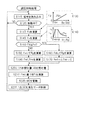
- FIG. 2 is an exemplary flowchart showing a process of pressure regulation control including regenerative cooperative control in the embodiment.
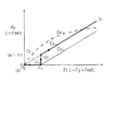
- FIG. 3 is an exemplary characteristic diagram showing the transition of the braking force in the embodiment.
- FIG. 4 is a schematic and exemplary perspective view of the brake operation unit of the embodiment.
- FIG. 5 is a schematic and exemplary rear view of the brake operation unit of the embodiment.
- FIG. 6 is a schematic and exemplary side view of the brake operation unit of the embodiment.
- FIG. 7 is a schematic and exemplary plan view of the brake operation unit of the embodiment.
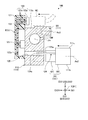
- FIG. 8 is a schematic and exemplary cross-sectional view orthogonal to the first central axis of the master cylinder of the brake operation unit of the embodiment.
- each symbol represents a generic name of each of the four wheels. For example, "WH” represents each wheel and "CW” represents each wheel cylinder.
- the operation of the braking control device SC is in an appropriate state, and the braking performed by the braking control device SC is called “controlled braking".
- the braking control device SC is in an abnormal state, the braking by only the operating force of the driver is called “manual braking”. Therefore, in the manual braking, the braking control device SC is not used.
- the braking control device SC will be described with reference to the overall configuration diagram of FIG. 1.
- the fluid passage is a passage for moving the brake fluid BF which is the hydraulic fluid of the brake control device, and corresponds to a brake pipe, a fluid unit flow passage, a hose and the like.
- the inside of the fluid passage is filled with the braking fluid BF.
- a so-called front-back type also referred to as “H type” is used as the two fluid passages.
- Front wheel system connected to front wheel cylinders CWi, CWj (also referred to as “front wheel wheel cylinder CWf"), and rear wheel system connected to rear wheel cylinders CWk, CWl (also referred to as “rear wheel wheel cylinder CWr”)
- a two-system fluid path is constituted by.
- the brake fluid BF is supplied from the reservoir RV and the hydraulic pressure Pw of the wheel cylinder CW is increased.
- Upstream side or “upper side”
- the side closer to the wheel cylinder CW (the side farther from the reservoir RV) is called “downstream side” or “lower side”.
- the vehicle is equipped with an electric motor GN for driving. That is, the vehicle is a hybrid vehicle or an electric vehicle.
- the driving electric motor GN also functions as a generator (generator) for energy regeneration.
- the generator GN is provided on the front wheels WHf.
- the electric motor / generator GN is controlled by the drive controller ECD.
- a distance sensor OB is provided in the vehicle so as to detect a distance (relative distance) Ob between the vehicle and an object existing in front of the vehicle (another vehicle, a fixed object, a person, a bicycle, etc.). It is provided.
- a camera, a radar or the like is adopted as the distance sensor OB.
- the distance Ob is input to the driving support controller ECJ.
- the driving assist controller ECJ calculates the required deceleration Gd based on the relative distance Ob.
- the required deceleration Gd is a target value of the vehicle deceleration for automatically braking on behalf of the driver without colliding with an object in front of the vehicle.
- a vehicle including the braking control device SC includes a braking operation member BP, a wheel cylinder CW, a reservoir RV, and a wheel speed sensor VW.
- the braking operation member (eg, brake pedal) BP is a member operated by the driver to decelerate the vehicle.
- the braking torque of the wheel WH is adjusted, and the braking force F (general term for the front wheel, rear wheel braking force Ff, Fr) is generated on the wheel WH.
- a rotating member for example, a brake disc
- a brake caliper is arranged so as to sandwich the rotating member KT, and a wheel cylinder CW is provided therein.
- the friction member for example, brake pad
- the reservoir (atmospheric pressure reservoir) RV is a tank for hydraulic fluid, in which the braking fluid BF is stored.
- the lower part of the reservoir RV is partitioned by a partition plate SK into a master reservoir chamber Ru connected to the master cylinder chamber Rm and a pressure control reservoir chamber Rd connected to the pressure control unit YC.
- the braking fluid BF can freely move over the partition plate SK between the master reservoir chamber Ru and the pressure regulating reservoir chamber Rd.
- Each wheel WH is equipped with a wheel speed sensor VW so as to detect the wheel speed Vw.
- the signal of the wheel speed Vw is used for independent braking control for each wheel such as anti-skid control (control for suppressing excessive deceleration slip of the wheel), vehicle stabilization control (control for suppressing excessive oversteer and understeer behavior), etc. To be done.
- the vehicle body speed Vx is calculated based on each wheel speed Vw detected by the wheel speed sensor VW.
- the braking control device SC includes an upper fluid unit YU and a lower fluid unit YL.
- the upper fluid unit YU is a fluid unit closer to the master cylinder CM
- the lower fluid unit YL is a fluid unit closer to the wheel cylinder CW.
- the inside of each fluid unit YU, YL is made liquid tight by the braking liquid BF.
- the upper fluid unit YU is controlled by the upper controller ECU
- the lower fluid unit YL is controlled by the lower controller ECL.
- the upper controller ECU and the lower controller ECL are connected via a communication bus BS so that respective signals (sensor detection value, calculated value, etc.) are shared.
- the upper fluid unit YU of the braking control device SC is composed of an operation amount sensor BA, an operation switch ST, a stroke simulator SS, a master unit YM, a pressure adjusting unit YC, and a regenerative cooperation unit YK.
- An operation amount sensor BA is provided so as to detect the operation amount Ba of the braking operation member (brake pedal) BP by the driver.
- An operation displacement sensor SP that detects the operation displacement Sp of the braking operation member BP is provided as the operation amount sensor BA.
- An operation force sensor FP is provided so as to detect the operation force Fp of the braking operation member BP.
- a simulator hydraulic pressure sensor PS is provided so as to detect the hydraulic pressure (simulator hydraulic pressure) Ps in the stroke simulator SS.
- An input hydraulic pressure sensor PN is provided so as to detect the hydraulic pressure (input hydraulic pressure) Pn in the input chamber Rn of the regenerative cooperation unit YK.
- the operation amount sensor BA is a general term for the operation displacement sensor SP and the like, and at least one of the operation displacement Sp, the operation force Fp, the simulator hydraulic pressure Ps, and the input hydraulic pressure Pn is adopted as the braking operation amount Ba.
- the detected braking operation amount Ba is input to the upper controller ECU.
- the operation switch ST is provided on the braking operation member BP so as to detect whether or not the driver operates the braking operation member BP.
- the braking operation switch ST outputs an OFF signal as the operation signal St.
- an ON signal is output as the operation signal St.
- the braking operation signal St is input to the controller ECU.
- a stroke simulator (simply referred to as “simulator”) SS is provided to generate an operating force Fp on the braking operation member BP.
- a piston and an elastic body are provided inside the simulator SS.
- the piston is pushed by the inflowing braking fluid BF.
- a force is applied to the piston in a direction to prevent the inflow of the braking fluid BF by the elastic body, so that an operation force Fp when the braking operation member BP is operated is formed.
- the master unit YM adjusts the hydraulic pressure (front wheel braking hydraulic pressure) Pwf in the front wheel cylinder CWf via the master cylinder chamber Rm.
- the master unit YM is configured to include a master cylinder CM, a master piston PM, and a master elastic body SM.
- the master cylinder CM is a cylinder member having a bottom.
- the master piston PM is a piston member inserted inside the master cylinder CM, and is movable in conjunction with the operation of the braking operation member BP.
- the inside of the master cylinder CM is divided into three hydraulic chambers Rm, Rs, and Ro by the master piston PM.
- a groove is formed in the first inner peripheral portion Mw of the master cylinder CM, and two seals SL are fitted into the groove.
- the outer peripheral portion (outer peripheral cylindrical surface) Mp of the master piston PM and the first inner peripheral portion (inner peripheral cylindrical surface) Mw of the master cylinder CM are sealed (sealed) by the two seals SL.
- the master piston PM can move smoothly along the central axis Jm of the master cylinder CM.
- the master cylinder chamber (also simply referred to as “master chamber”) Rm is defined by “the first inner peripheral portion Mw and the first bottom portion (bottom surface) Mu of the master cylinder CM” and the first end portion Mv of the master piston PM. It is a partitioned hydraulic chamber.
- a master cylinder fluid passage HM is connected to the master chamber Rm, and finally connected to the front wheel cylinder CWf via the lower fluid unit YL.
- a flange (flange) Tm is provided on the master piston PM.
- the inside of the master cylinder CM is partitioned into a servo hydraulic chamber (simply referred to as “servo chamber”) Rs and a rear hydraulic chamber (simply referred to as “rear chamber”) Ro.
- a seal SL is provided on the outer peripheral portion of the collar portion Tm, and the collar portion Tm and the second inner peripheral portion Md of the master cylinder CM are sealed.
- the servo chamber Rs is a hydraulic chamber defined by “the second inner peripheral portion Md and the second bottom portion (bottom surface) Mt of the master cylinder CM” and the first surface Ms of the collar portion Tm of the master piston PM. ..
- the master chamber Rm and the servo chamber Rs are arranged so as to face each other with the master piston PM (particularly, the collar portion Tm) interposed therebetween.
- the front wheel pressure adjusting fluid passage HF is connected to the servo chamber Rs, and the second adjusting hydraulic pressure Pc is introduced from the pressure adjusting unit YC.
- the rear chamber Ro is a hydraulic chamber partitioned by the second inner peripheral portion Md of the master cylinder CM, the stepped portion Mz, and the second surface Mo of the collar portion Tm of the master piston PM.
- the rear chamber Ro is sandwiched between the master hydraulic chamber Rm and the servo hydraulic chamber Rs in the direction of the central axis Jm, and is located between them.
- a simulator fluid path HS is connected to the rear chamber Ro. The amount of the brake fluid BF in the upper fluid unit YU is adjusted by the rear chamber Ro.
- a recess Mx is provided at the first end Mv of the master piston PM.
- a master elastic body (for example, a compression spring) SM is provided between the recess Mx and the first bottom Mu of the master cylinder CM.
- the master elastic body SM presses the master piston PM against the second bottom portion Mt of the master cylinder CM in the direction of the central axis Jm of the master cylinder CM.
- the stepped portion My of the master piston PM and the second bottom portion Mt of the master cylinder CM are in contact with each other.
- the position of the master piston PM in this state is referred to as the "initial position of the master unit YM".
- a through hole Ac is provided in the master cylinder CM between the two seals SL (for example, cup seals).
- the through hole Ac is connected to the master reservoir chamber Ru via the makeup fluid passage HU.
- a through hole Ap is provided near the first end Mv of the master piston PM.
- an urging force Fb (referred to as “retraction force”) in the retreat direction Hb along the central axis Jm is generated by an internal pressure (which is “master cylinder hydraulic pressure” and also referred to as “master hydraulic pressure”) Pm. It is given to the master piston PM.
- the servo chamber Rs applies an urging force Fa (referred to as “advancing force”) that opposes the retreat force Fb to the master piston PM by its internal pressure (that is, the introduced second adjustment hydraulic pressure Pc).
- a master hydraulic pressure sensor PQ is provided so as to detect the master hydraulic pressure Pm.
- the master hydraulic pressure sensor PQ can be provided in the master cylinder fluid passage HM. Further, the master hydraulic pressure sensor PQ may be included in the lower fluid unit YL.
- the pressure receiving area rs of the first surface Ms of the collar portion Tm (that is, the pressure receiving area of the servo chamber Rs) rs is equal to the pressure receiving area of the first end Mv of the master piston PM (that is, the pressure receiving area of the master chamber Rm) rm. It is set to be equal.
- the hydraulic pressure Pc (as a result, the servo hydraulic pressure Pv) introduced into the servo chamber Rs and the hydraulic pressure Pm in the master chamber Rm are the same in the steady state.
- the hydraulic pressure Pwf of the front wheel cylinder CWf and the hydraulic pressure Pwr of the rear wheel cylinder CWr are independently and individually adjusted by the pressure adjusting unit YC. Specifically, the braking fluid pressure Pwf of the front wheels WHf provided with the generator GN is adjusted to be equal to or lower than the braking fluid pressure Pwr of the rear wheels WHr not provided with the generator GN.
- the pressure adjusting unit YC includes an electric pump DC, a check valve GC, first and second pressure adjusting valves UB and UC, and first and second adjusting hydraulic pressure sensors PB and PC.
- the electric pump DC is composed of one electric motor MC and one fluid pump QC.
- the electric motor MC and the fluid pump QC are fixed so that the electric motor MC and the fluid pump QC rotate integrally.
- the electric pump DC (in particular, the electric motor MC) is a power source for increasing the braking fluid pressure Pw during controlled braking.
- the electric motor MC is controlled by the controller ECU.
- a three-phase brushless motor is adopted as the electric motor MC.
- the brushless motor MC is provided with a rotation angle sensor KA that detects the rotor position (rotation angle) Ka of the brushless motor MC.
- the switching element of the bridge circuit is controlled based on the rotation angle (actual value) Ka, and the electric motor MC is driven. That is, the directions of the energization amounts of the coils of each of the three phases (U phase, V phase, W phase) (that is, the excitation directions) are sequentially switched, and the brushless motor MC is rotationally driven.
- the drive circuit DR is provided with an energization amount sensor that detects the actual energization amount Ia (general term for each phase) of the electric motor MC.
- a current sensor is provided as the energization amount sensor, and the supply current Ia to the electric motor MC is detected.
- the suction port Qs of the fluid pump QC is connected to the reservoir RV (particularly, the pressure regulating reservoir chamber Rd) via the first reservoir fluid passage HV.
- the pressure regulating fluid passage HC is connected to the discharge port Qt of the fluid pump QC.
- the electric pump DC particularly, the fluid pump QC
- the braking fluid BF is sucked from the first reservoir fluid passage HV through the suction opening Qs and discharged from the discharge opening Qt to the pressure regulating fluid passage HC.
- a gear pump is adopted as the fluid pump QC.
- a check valve GC (also called “check valve”) is provided in the pressure regulating fluid path HC.
- the check valve GC allows the brake fluid BF to move from the first reservoir fluid passage HV toward the pressure regulating fluid passage HC, but moves from the pressure regulating fluid passage HC toward the reservoir fluid passage HV (that is, , Backflow of the braking fluid BF) is prevented. That is, the electric pump DC is rotated only in one direction.
- the end portion Bv of the pressure regulating fluid passage HC on the side opposite to the discharge portion Qt is connected to the first reservoir fluid passage HV.
- Two pressure regulating valves UB and UC are provided in series in the pressure regulating fluid passage HC.
- the pressure regulating fluid passage HC is provided with a first pressure regulating valve UB (corresponding to “first electromagnetic valve”).
- the second pressure regulating valve UC (corresponding to the "second electromagnetic valve”) is arranged between the first pressure regulating valve UB and the portion Bv.
- the first and second pressure regulating valves UB and UC are linear type solenoid valves (“proportional valve”, or “proportional valve”, in which the valve opening amount (lift amount) is continuously controlled based on the energized state (eg, supply current)). It is also called a "differential pressure valve”).
- the first and second pressure regulating valves UB and UC are controlled by the controller ECU based on the drive signals Ub and Uc. Normally-open solenoid valves are used as the first and second pressure regulating valves UB and UC.
- the braking fluid BF is pumped up from the first reservoir fluid passage HV through the suction port Qs of the fluid pump QC and discharged from the discharge port Qt. Then, the braking fluid BF passes through the check valve GC, the first pressure regulating valve UB, and the second pressure regulating valve UC and is returned to the reservoir fluid passage HV.
- the first reservoir fluid passage HV and the pressure adjusting fluid passage HC form a return passage (a fluid passage in which the flow of the braking fluid BF returns to the original flow), and a check valve is provided in the return passage.
- the valve GC and the first and second pressure regulating valves UB and UC are provided in series.
- the braking fluid BF is recirculated in the order of “HV ⁇ QC (Qs ⁇ Qt) ⁇ GC ⁇ UB ⁇ UC ⁇ HV” as indicated by the dashed arrow (A). (That is, a “reflux path” is formed).
- the first and second pressure regulating valves UB and UC are in the fully open state (these are normally open types, so that they are not energized), the hydraulic pressures (regulating hydraulic pressures) Pb and Pc in the pressure regulating fluid passage HC are Both are approximately “0 (atmospheric pressure)”.
- the second regulating hydraulic pressure Pc regulated by the second regulating valve UC is the first regulating hydraulic pressure Pb. It is below.
- the second pressure adjusting valve UC adjusts the second adjusting hydraulic pressure Pc to increase from “0 (atmospheric pressure)”
- the first pressure adjusting valve UB adjusts the first adjusting hydraulic pressure Pb to the second
- the adjusted hydraulic pressure Pc is adjusted to increase.
- the pressure adjusting fluid passage HC is provided with first and second adjusting liquid pressure sensors PB and PC so as to detect the first and second adjusting liquid pressures Pb and Pc.
- the pressure regulating fluid passage HC is branched to the rear wheel pressure regulating fluid passage HR at a portion Bh between the fluid pump QC and the first pressure regulating valve UB.
- the rear wheel pressure regulating fluid passage HR is connected to the rear wheel wheel cylinder CWr (CWk, CWl) via the lower fluid unit YL. Therefore, the first adjusting hydraulic pressure Pb adjusted by the first pressure adjusting valve UB is directly introduced (supplied) to the rear wheel hall cylinder CWr.
- the pressure regulating fluid passage HC is branched to the front wheel pressure regulating fluid passage HF at a portion Bg between the first pressure regulating valve UB and the second pressure regulating valve UC.
- the front wheel pressure regulating fluid path HF is connected to the servo chamber Rs.
- the second adjusting hydraulic pressure Pc adjusted by the second pressure adjusting valve UC is introduced (supplied) to the servo chamber Rs. Since the master cylinder CM is connected to the front wheel cylinder CWf (CWi, CWj) via the lower fluid unit YL, the second adjusted hydraulic pressure Pc is transferred to the front wheel cylinder CWf via the master cylinder CM. Indirectly introduced. That is, the second adjusted hydraulic pressure Pc is supplied to the front wheel cylinder CWf in the order of “Rs ⁇ Rm ⁇ CWf”.
- the pressure adjusting unit YC is configured to include two pressure adjusting electromagnetic valves UB and UC, and the first pressure adjusting valve UB adjusts the braking fluid BF discharged from the electric pump DC to the first adjustment fluid pressure Pb.
- the adjusted hydraulic pressure Pb is introduced into the rear wheel wheel cylinder CWr.
- the second pressure adjusting valve UC adjusts the first adjusting hydraulic pressure Pb to the second adjusting hydraulic pressure Pc, and the second adjusting hydraulic pressure Pc is introduced into the servo chamber Rs.
- the pressure adjusting unit YC is provided with a bypass fluid path HD that connects the reservoir RV and the servo chamber Rs in parallel with the pressure adjusting fluid path HC.
- a check valve GD is provided in the fluid path HD.
- the check valve GD allows the flow of the braking fluid BF from the reservoir RV to the servo chamber Rs, but blocks the flow from the servo chamber Rs to the reservoir RV.
- the master piston PM is also moved in the forward direction Ha by the operating force of the driver, and the volume of the servo chamber Rs can be increased.
- the liquid amount of the volume increase of the servo chamber Rs caused by the driver's operation is supplied via the bypass fluid passage HD and the check valve GD. Since the amount of the brake fluid BF supplied by the electric pump DC is efficiently used for increasing the brake fluid pressure Pw, the boost responsiveness during sudden braking can be improved.
- the regenerative cooperation unit YK achieves cooperative control of friction braking and regenerative braking (referred to as "regenerative cooperative control"). That is, a state in which the braking fluid pressure Pw is not generated although the braking operation member BP is operated by the regenerative cooperation unit YK can be formed.
- the regenerative cooperation unit YK includes an input cylinder CN, an input piston PK, an input elastic body SN, a first opening / closing valve VA, a second opening / closing valve VB, a stroke simulator SS, a simulator hydraulic pressure sensor PS, and an input hydraulic pressure sensor PN. Composed.
- the input cylinder CN is a cylinder member having a bottom portion, which is fixed to the master cylinder CM.
- the input piston PK is a piston member inserted inside the input cylinder CN.
- the input piston PK is mechanically connected to the braking operation member BP via a clevis (U-shaped link) so as to interlock with the braking operation member BP.
- the input piston PK is provided with a flange (flange) Tn.
- An input elastic body (for example, a compression spring) SN is provided between the mounting surface Ma of the input cylinder CN on the master cylinder CM and the flange portion Tn of the input piston PK.
- the input elastic body SN presses the flange portion Tn of the input piston PK against the bottom portion Mb of the input cylinder CN in the direction of the central axis Jm.
- the stepped portion My of the master piston PM is in contact with the second bottom portion Mt of the master cylinder CM, and the flange portion Tn of the input piston PK is in contact with the bottom portion Mb of the input cylinder CN.
- the clearance Ks between the master piston PM (particularly, the end surface Mq) and the input piston PK (particularly, the end surface Mg) is set to a predetermined distance ks (referred to as “initial clearance”) inside the input cylinder CN.
- the master piston PM and the input piston PK are separated by a predetermined distance ks.
- the predetermined distance ks corresponds to the maximum value of the regeneration amount Rg.
- the input piston PK is moved in the forward direction Ha from its initial position.
- the second adjusted hydraulic pressure Pc remains “0”
- the master piston PM remains in the initial position, and thus the gap Ks (the end surface Mg of the input piston PK and the master piston PM) is advanced as the input piston PK advances.
- the distance from the end surface Mq of PM) gradually decreases.
- the second adjusted hydraulic pressure Pc is increased from "0”
- the master piston PM is moved in the forward direction Ha from its initial position. Therefore, the clearance Ks can be adjusted independently of the braking operation amount Ba within the range of “0 ⁇ Ks ⁇ ks” by the second adjustment hydraulic pressure Pc. That is, by adjusting the second adjusting hydraulic pressure Pc, the gap Ks is adjusted and regenerative cooperative control is achieved.
- the input cylinder CN is connected to the reservoir RV (particularly, the pressure regulating reservoir chamber Rd) via the second reservoir fluid passage HT.
- a part of the second reservoir fluid passage HT can be shared with the first reservoir fluid passage HV.
- the first reservoir fluid passage HV and the second reservoir fluid passage HT be separately connected to the reservoir RV.
- the fluid pump QC sucks the braking fluid BF from the reservoir RV via the first reservoir fluid passage HV, but at this time, bubbles may be mixed in the first reservoir fluid passage HV. Therefore, the second reservoir fluid passage HT does not have a common portion with the first reservoir fluid passage HV and is separate from the first reservoir fluid passage HV so as to prevent bubbles from entering the input cylinder CN and the like. Is connected to the reservoir RV.
- the two on-off valves VA and VB are provided in series in the second reservoir fluid passage HT.
- the first and second opening / closing valves VA and VB are two-position solenoid valves (also referred to as “on / off valves”) having an open position (communication state) and a closed position (blocking state).
- the first and second on-off valves VA and VB are controlled by the upper controller ECU based on the drive signals Va and Vb.
- a normally closed solenoid valve is adopted as the first on-off valve VA, and a normally open solenoid valve is adopted as the second on-off valve VB.
- the second reservoir fluid passage HT is connected to the simulator fluid passage HS at a connecting portion Bs between the first opening / closing valve VA and the second opening / closing valve VB.
- one end of the simulator fluid path HS is connected to the rear chamber Ro and the other end is connected to the part Bs.
- a stroke simulator SS is provided in the simulator fluid path HS.
- the simulator SS executes the regenerative cooperative control, and when the first opening / closing valve VA is in the open position and the second opening / closing valve VB is in the closed position, the operating force Fp of the braking operation member BP is generated.
- a piston and an elastic body for example, a compression spring
- the braking fluid BF is moved from the input cylinder CN to the simulator SS, and the inflowing braking fluid BF pushes the piston.
- An elastic body applies a force to the piston in a direction to prevent the inflow of the braking fluid BF.
- the elastic body forms an operating force Fp when the braking operation member BP is operated.
- a simulator fluid pressure sensor PS is provided in the simulator fluid path HS so as to detect fluid pressure (simulator fluid pressure) Ps in the simulator SS.
- the input hydraulic pressure is detected so as to detect the hydraulic pressure (the hydraulic pressure of the input chamber Rn, which is referred to as “input hydraulic pressure”) Pn between the first opening / closing valve VA of the second reservoir fluid path HT and the input chamber Rn.
- a sensor PN is provided.
- the simulator hydraulic pressure sensor PS and the input hydraulic pressure sensor PN are one of the braking operation amount sensors BA described above.
- the detected hydraulic pressures Ps and Pn are input to the upper controller ECU as the braking operation amount Ba.
- the upper controller ECU Based on the braking operation amount Ba, the operation signal St, and the first and second adjusted hydraulic pressures (detection values) Pb and Pc, the upper controller ECU uses the electric motor MC and the solenoid valves VA, VB, UB, and UC. Is controlled. Specifically, the upper controller ECU calculates drive signals Va, Vb, Ub, Uc for controlling the various solenoid valves VA, VB, UB, UC. Similarly, a drive signal Mc for controlling the electric motor MC is calculated. Then, the solenoid valves VA, VB, UB, UC and the electric motor MC are driven based on the drive signals Va, Vb, Ua, Ub, Mc.
- the upper controller (electronic control unit) ECU is network-connected to the lower controller ECL and controllers of other systems (drive controller ECD, driving support controller ECJ, etc.) via an in-vehicle communication bus BS.
- a regeneration amount (target value) Rg is transmitted from the upper controller ECU to the driving controller ECD through the communication bus BS so as to execute the regenerative coordination control.
- the required deceleration (target value) Gd is transmitted from the driving support controller ECJ to the upper controller ECU through the communication bus BS.
- the lower fluid unit YL is a known fluid unit including a master fluid pressure sensor PQ, a plurality of solenoid valves, an electric pump, and a low pressure reservoir.
- the lower fluid unit YL is controlled by the lower controller ECL.
- the wheel speed Vw, yaw rate, steering angle, longitudinal acceleration, lateral acceleration, etc. are input to the ECL.
- the lower controller ECL calculates the vehicle body speed Vx based on the wheel speed Vw. Then, based on the vehicle body speed Vx and the wheel speed Vw, anti-skid control is executed so as to suppress an excessive deceleration slip (for example, wheel lock) of the wheel WH.
- an excessive deceleration slip for example, wheel lock
- the lower controller ECL performs vehicle stabilization control (so-called ESC) that suppresses unstable behavior (excessive oversteer behavior, understeer behavior) of the vehicle based on the yaw rate. That is, the braking fluid pressure Pw of each wheel WH is individually controlled by the lower fluid unit YL.
- the calculated vehicle speed Vx is input to the upper controller ECU via the communication bus BS.
- the input chamber Rn and the rear chamber Ro are connected by the open position of the first opening / closing valve VA, and the simulator SS is connected to the input chamber Rn. Connected to Rn. Further, the closed position of the second on-off valve VB disconnects the simulator SS from the reservoir RV.
- the input piston PK is moved in the forward direction Ha by the operation of the braking operation member BP, and the liquid amount flowing out from the input chamber Rn due to the movement flows into the simulator SS, and the operating force Fp of the braking operation member BP is formed.
- the input piston PK is moved from its initial position in the forward direction Ha, but at this time, the second adjustment hydraulic pressure Pc remains "0", so the master piston PM is Not moved. Therefore, the gap Ks (the distance between the end surface Mg of the input piston PK and the end surface Mq of the master piston PM) gradually decreases as the input piston PK advances.
- the controller ECU controls the pressure adjusting unit YC and adjusts the first and second adjusting hydraulic pressures Pb and Pc.
- the first adjusting hydraulic pressure Pb is directly applied to the rear wheel cylinder CWr through the rear wheel pressure adjusting fluid passage HR and the lower fluid unit YL.
- the second adjustment hydraulic pressure Pc is applied to the servo chamber Rs through the front wheel pressure adjustment fluid passage HF.
- the master chamber Rm is shut off from the reservoir RV. Further, when the second adjustment hydraulic pressure Pc is increased, the braking fluid BF is pumped at the master hydraulic pressure Pm from the master cylinder CM toward the front wheel cylinder CWf. A force (backward force) Fb in the backward direction Hb is applied to the master piston PM by the master hydraulic pressure Pm.
- the servo chamber Rs generates a force (forward force) Fa in the forward direction Ha by the second adjustment hydraulic pressure Pc so as to oppose (oppose) the backward force Fb.
- the master hydraulic pressure Pm is increased / decreased according to the increase / decrease in the adjusted hydraulic pressure Pc.
- the gap Ks is braked within the range of “0 ⁇ Ks ⁇ ks” by the second adjustment hydraulic pressure Pc. It can be adjusted independently of the manipulated variable Ba. That is, the regenerative cooperative control is executed by adjusting the gap Ks by the second adjusting hydraulic pressure Pc.
- the second adjusting hydraulic pressure Pc is reduced by the pressure adjusting unit YC.
- the master piston PM is moved in the backward direction Hb.
- the elastic force of the compression spring SM causes the master piston PM (in particular, the stepped portion My) to come into contact with the second bottom portion Mt of the master cylinder CM (initial position). Returned to.
- the first and second on-off valves VA, VB are not energized. Therefore, the first on-off valve VA is in the closed position and the second on-off valve VB is in the open position. Due to the closed position of the first opening / closing valve VA, the input chamber Rn is in a fluid locked state (sealed state), and the input piston PK and the master piston PM are prevented from moving relative to each other. Further, the rear chamber Ro is fluidly connected to the reservoir RV through the second reservoir fluid passage HT by the open position of the second opening / closing valve VB. Therefore, the volume of the rear chamber Ro is reduced by the movement of the master piston PM in the forward direction Ha, but the liquid amount accompanying the volume reduction is discharged toward the reservoir RV. The input piston PK and the master piston PM are integrally moved in association with the operation of the braking operation member BP, and the brake fluid BF is pressure-fed from the master chamber Rm to the front wheel cylinder CWf.
- the “pressure regulation control” is drive control of the electric motor MC and the first and second pressure regulation valves UB and UC for regulating the first and second regulation hydraulic pressures Pb and Pc.
- the control algorithm is programmed in the upper controller ECU.
- step S110 the braking operation amount Ba, the operation signal St, the first and second adjustment hydraulic pressures (detection values) Pb and Pc, the required deceleration Gd, and the vehicle body speed Vx are read.
- the operation amount Ba is detected by an operation amount sensor BA (operation displacement sensor SP, input hydraulic pressure sensor PN, simulator hydraulic pressure sensor PS, etc.).
- the operation signal St is detected by the operation switch ST.
- the first and second adjusting hydraulic pressures Pb and Pc are detected by the first and second adjusting hydraulic pressure sensors PB and PC provided in the pressure adjusting fluid passage HC.
- the required deceleration Gd by automatic braking is acquired from the driving support controller ECJ via the communication bus BS.
- the vehicle body speed Vx is acquired from the lower controller ECL via the communication bus BS.
- the vehicle body speed Vx may be calculated by the upper controller ECU based on the wheel speed Vw when the wheel speed Vw is input to the upper controller ECU.
- step S120 "whether or not braking is being performed" is determined based on at least one of the braking operation amount Ba and the braking operation signal St. For example, when the operation amount Ba is larger than the predetermined value bo, step S120 is affirmative and the process proceeds to step S130. On the other hand, if the braking operation amount Ba is less than or equal to the predetermined value bo, step S120 is denied and the process is returned to step S110.
- the predetermined value bo is a preset constant corresponding to the play of the braking operation member BP. If the operation signal St is on, the process proceeds to step S130, and if the operation signal St is off, the process returns to step S110.
- step S120 "whether or not braking is being performed" is determined based on the required deceleration Gd. For example, when the requested deceleration Gd is larger than the predetermined value go, the step S120 is affirmative and the process proceeds to the step S130. On the other hand, if the required deceleration Gd is less than or equal to the predetermined value go, step S120 is denied and the process is returned to step S110.
- the predetermined value go is a preset constant (for example, “0”).
- the required braking force Fd is calculated based on the operation amount Ba as shown in block X130.
- the required braking force Fd is a target value of the total braking force F that acts on the vehicle, and is a braking force that is a combination of the “friction braking force Fm by the braking control device SC” and the “regenerative braking force Fg by the generator GN”.
- the required braking force Fd is determined to be “0” in the range of the operation amount Ba from “0” to the predetermined value bo according to the calculation map Zfd, and the operation amount Ba increases when the operation amount Ba is the predetermined value bo or more. Along with this, it is calculated so as to monotonically increase from “0”.
- the required braking force Fd is calculated based on the required deceleration Gd.
- the required braking force Fd is determined to be “0" when the required deceleration Gd is “0" or more and less than the predetermined value go, and when the required deceleration Gd is the predetermined value bo or more, " It is decided to increase monotonically from "0".
- step S140 the maximum value of the regenerative braking force (called “maximum regenerative force”) Fx is calculated based on the vehicle body speed Vx and the calculation map Zfx.
- the regeneration amount of the generator GN is limited by the rating of the power transistor (IGBT or the like) of the drive controller ECD and the charge acceptability of the battery.
- the regeneration amount of the generator GN is controlled to a predetermined electric power (electrical energy per unit time). Since the electric power (power) is constant, the regenerative torque around the wheel shaft by the generator GN is inversely proportional to the rotation speed of the wheel WH (that is, the vehicle body speed Vx). Further, when the rotation speed Ng of the generator GN decreases, the regeneration amount decreases. Further, an upper limit value is set for the regeneration amount.
- the maximum regenerative force Fx increases as the vehicle body speed Vx increases in the range where the vehicle body speed Vx is “0” or more and less than the first predetermined speed vo. Is set as follows. Further, in the range where the vehicle body speed Vx is equal to or higher than the first predetermined speed vo and lower than the second predetermined speed vp, the maximum regenerative force Fx is set to the upper limit value fx. When the vehicle body speed Vx is equal to or higher than the second predetermined speed vp, the maximum regenerative force Fx is set to decrease as the vehicle body speed Vx increases.
- the relationship between the vehicle body speed Vx and the maximum regenerative force Fx is represented by a hyperbola (that is, regenerative power is constant).
- the respective predetermined values vo and vp are preset constants.
- the rotation speed Ng of the generator GN may be adopted instead of the vehicle body speed Vx.
- step S150 "whether the required braking force Fd is less than or equal to the maximum regenerative force Fx" is determined based on the required braking force Fd and the maximum regenerative force Fx. That is, it is determined whether or not the braking force Fd required by the driver can be achieved only by the regenerative braking force Fg. If “Fd ⁇ Fx” and step S150 is positive, the process proceeds to step S160. On the other hand, if “Fd> Fx” and step S150 is negative, the process proceeds to step S180.
- step S160 the regeneration amount Rg is calculated based on the required braking force Fd.
- the regeneration amount Rg is a target value of the regeneration amount of the generator GN.
- the regeneration amount Rg is transmitted from the braking controller ECU to the drive controller ECD via the communication bus BS.
- step S170 the target friction braking forces Fmf and Fmr for the front and rear wheels are calculated to be "0". In this case, friction braking is not used for vehicle deceleration, and the required braking force Fd is achieved only by regenerative braking.
- step S180 the regenerative amount (target value) Rg is calculated based on the maximum regenerative power Fx. Similar to step S160, the regeneration amount Rg is transmitted to the drive controller ECD via the communication bus BS. In this case, the generator GN produces the maximum regenerative braking force that can be generated.
- step S190 the front and rear wheel friction braking forces Fmf and Fmr are determined based on the required braking force Fd and the maximum regenerative force Fx. The front and rear wheel friction braking forces Fmf and Fmr are target values of the braking force to be achieved by friction braking.
- the rear wheel friction braking force Fmr is calculated as the rear wheel reference force Fs
- the front wheel friction braking force Fmf is calculated from the supplementary braking force Fh.
- step S190 the front and rear wheel friction braking forces Fmf and Fmr are calculated in consideration of the front-rear distribution of the braking force F including the regenerative braking force Fg.
- the required braking force Fd can be achieved by the regenerative braking force Fg and the rear wheel reference force Fs (rear wheel braking force considering the front-rear distribution) (that is, when “Fh ⁇ Fs”)
- the rear wheel friction braking force Fmr is determined and added so as to satisfy the required braking force Fd.
- the front wheel is made to satisfy the shortage.
- the friction braking force Fmf is determined.
- the regeneration amount Rg can be maximized and the front-rear distribution of the braking force F can be optimized.
- step S200 the first opening / closing valve VA is driven to the open position and the second opening / closing valve VB is driven to the closed position.
- step S210 the target hydraulic pressure Pt (Ptf, Ptr) is calculated based on the target value Fm (Fmf, Fmr) of the friction braking force. That is, the frictional braking force Fm is converted into a hydraulic pressure to determine the target hydraulic pressure Pt.
- the rear wheel target hydraulic pressure Ptr is a target value of the hydraulic pressure of the rear wheel cylinder CWr corresponding to the first adjusted hydraulic pressure Pb.
- the front wheel target hydraulic pressure Ptf is a target value of the hydraulic pressure of the front wheel wheel cylinder CWf corresponding to the second adjusted hydraulic pressure Pc.
- step S220 the electric motor MC is driven, and the circulation of the braking fluid BF including the fluid pump QC is formed.
- step S230 based on the rear wheel target hydraulic pressure Ptr and the first adjusted hydraulic pressure Pb (detection value of the first adjusted hydraulic pressure sensor PB), the first adjusted hydraulic pressure Pb is set to the rear wheel target hydraulic pressure.
- the first pressure regulating valve UB is servo-controlled so as to match the pressure Ptr.
- the second adjusted hydraulic pressure Pc matches the front wheel target hydraulic pressure Ptf.
- the second pressure regulating valve UC is servo-controlled. In servo control, feedback control is performed so that the actual values Pb and Pc match the target value Pt.
- the first and second pressure regulating valves UB and UC are arranged in series in the pressure regulating fluid passage HC. For this reason, in the hydraulic pressure feedback control of the first and second adjustment hydraulic pressures Pb and Pc, they influence each other and so-called control interference may occur. In such a case, the control of the second adjustment hydraulic pressure Pc for the front wheels WHf has priority over the control of the first adjustment hydraulic pressure Pb for the rear wheels WHr.
- the front wheel braking force Ff is based on the fact that it contributes to the total braking force F higher than the rear wheel braking force Fr.
- the front-rear distribution of the braking force F in the regenerative cooperative control will be described with reference to the characteristic diagram of FIG.
- the regeneration generator GN is provided on the front wheel WHf, and the regenerative braking force Fg acts on the front wheel WHf in addition to the friction braking force Fmf.
- the generator GN is not provided for the rear wheels WHr, the regenerative braking force does not act on the rear wheels WHr, but only the friction braking force Fmr acts.
- the characteristic Ca indicated by the alternate long and short dash line represents a so-called ideal braking force distribution in which the change in the ground load (vertical force) of the front and rear wheels WHf and WHr due to vehicle deceleration is taken into consideration.
- the characteristic Cb is referred to as a “reference characteristic”.
- the reference characteristic Cb is based on “the pressure receiving areas of the front and rear wheel wheel cylinders CWf and CWr”, “the effective braking radius of the rotating members KTf and KTr”, and “the friction coefficient of the front and rear wheel friction materials”.
- the reference characteristic Cb is ideally distributed within the range of normal braking (in the area excluding the area in which the maximum braking force is generated) so that the rear wheel WHr does not lock the wheels ahead of the front wheel WHf.
- the pressure receiving area of the wheel cylinder CW, the effective braking radius of the rotating member KT, and the friction coefficient of the friction material are set so as to be smaller than the characteristic Ca.
- the braking force distribution control (so-called EBD control) is executed based on the wheel speed Vw so that the deceleration slip of the rear wheel WHr does not become larger than the deceleration slip of the front wheel WHf. ..
- the front and rear wheel friction braking forces Fmf and Fmr target values of friction braking force
- the required braking force Fd can be achieved by the regenerative braking force Fg and the rear wheel reference force Fs
- the front wheel friction control is performed according to the front wheel instruction force Fc.
- the power Fmf is increased from "0". That is, when the required braking force Fd cannot be achieved by the regenerative braking force Fg and the rear wheel reference force Fs, the front wheel friction braking force Fmf is determined so as to satisfy the shortfall.
- the front wheel target hydraulic pressure Ptf is calculated based on the front wheel friction braking force (target value) Fmf.
- the second pressure regulating valve UC adjusts the second adjusted hydraulic pressure Pc, and finally the front wheel braking hydraulic pressure Pwf is controlled.
- the rear wheel target hydraulic pressure Ptr is calculated based on the rear wheel friction braking force Fmr.
- the first pressure regulating valve UB adjusts the first regulated hydraulic pressure Pb, and finally the rear wheel braking hydraulic pressure Pwr is controlled.
- the front and rear wheel target hydraulic pressures Ptf, Ptr are increased in consideration of the front-rear ratio (for example, the rear wheel ratio Hr) so that the operating point of the braking force F follows the reference characteristic Cb. 2 Both adjusting hydraulic pressures Pb and Pc are increased.
- the control in the regenerative coordinated control is performed.
- the power distribution changes like the characteristic Cc.
- the rear wheel braking force Fr in the characteristic Cc is smaller than the rear wheel braking force Fr in the ideal distribution characteristic Ca. Therefore, with the characteristic Cc, the vehicle stability is secured, but the rear wheel braking force Fr cannot be fully utilized.
- the braking control device SC calculates the front wheel and rear wheel friction braking forces (target values) Fmf, Fmr in consideration of the predetermined rear wheel ratio Hr, and adjusts the hydraulic pressures Pc, Pb (that is, The braking fluid pressures Pwf, Pwr) are adjusted independently of the braking operation (or the braking request) and separately. Due to the distribution characteristic Cx by this, the regeneration amount Rg of the generator GN can be maximized and the front-rear distribution of the braking force F can be optimized. That is, the braking forces Ff and Fr of the front and rear wheels are preferably ensured, the vehicle stability is maintained, and a sufficient amount of regenerable energy can be ensured.
- FIG. 4 is a perspective view of the brake operating unit 100
- FIG. 5 is a rear view of the brake operating unit 100
- FIG. 6 is a side view of the brake operating unit 100
- FIG. 7 is a plan view of the brake operating unit 100
- FIG. FIG. 4 is a cross-sectional view orthogonal to the central axis Jm of the brake operation unit 100.
- directional arrows are shown when the brake operation unit 100 is mounted on a vehicle.
- the direction X indicates the front side of the vehicle
- the direction Y indicates the right side in the vehicle width direction
- the direction Z indicates the upper side of the vehicle.
- front, rear, front-rear direction, rightward, leftward, upper, lower, and up-down directions all indicate directions in the vehicle.
- the right side and the left side are the right side and the left side when facing the front of the vehicle.
- “intersection” does not necessarily mean orthogonality, and includes a state where there is a substantially orthogonal and a realizable obtuse angle or acute angle difference.
- the brake operation unit 100 includes a housing 110.
- the housing 110 is made of a metal material such as an aluminum alloy.
- Components such as a master cylinder CM, an electric pump DC, a stroke simulator SS, an upper controller ECU, and a reservoir RV are fixed to the housing 110. These components are fixed to the housing 110 while being at least partially accommodated in the holes provided in the housing 110, or are attached to the outside of the housing 110.
- a passage (not shown) for the hydraulic fluid is provided in the housing 110, and a hydraulic circuit (fluid circuit) is configured by connecting the respective components through the passage.
- the housing 110 may also be called a body or a block.
- the central axis Jm of the master cylinder CM passes through the substantial center of the housing 110 and extends in the front-rear direction (direction X). That is, the master cylinder CM extends in the front-rear direction.
- the connection portion 101 connected to the braking operation member BP projects rearward from the rear end of the master cylinder CM.
- the operating force of the braking operation member BP is transmitted to the input piston PK (see FIG. 1) via the connecting portion 101, and the master piston PM is interlocked with the operation of the braking operation member BP.
- the braking operation member BP is an example of an operation member
- the input piston PK and the master piston PM are examples of pistons
- the central axis Jm of the master cylinder CM is an example of a first central axis.
- the electric pump DC has the electric motor MC and the fluid pump QC as described above. As shown in FIGS. 4 and 5, the electric pump DC is located below the master cylinder CM.
- the central axis Ax2 as the rotation center of the rotor (not shown) of the electric motor MC and the central axis Jm of the master cylinder CM are in a twisted position. In other words, the central axis Ax2 of the electric motor MC is separated downward from the central axis Jm of the master cylinder CM and intersects the direction D1 parallel to the central axis Jm of the master cylinder CM.
- the direction D1 is the front, and the central axis Ax2 extends in the vehicle width direction orthogonal to the direction D1.
- the central axis Ax2 is an example of a second central axis.
- the direction D1 is an example of a direction parallel to the first central axis.
- the fluid pump QC is housed in the housing 110 and the electric motor MC is exposed outside the housing 110, but the electric pump DC is not limited to such a form.
- the fluid pump QC is, for example, a gear pump, but is not limited to this, and may be a single-cylinder piston pump (piston cylinder), a pump of another form, or a hydraulic fluid discharge mechanism.
- the linear motion member of the rotation / linear motion conversion mechanism moves the piston in the cylinder of the fluid pump QC according to the rotation of the rotor of the electric motor MC, whereby the liquid chamber expands and contracts to suck the working fluid.
- it may be configured to discharge.
- the electric pump DC may be entirely housed in the housing 110, or the electric pump DC may be entirely attached to the outside of the housing 110 and integrated with the housing 110.
- the electric pump DC is an example of an electric discharge unit
- the electric motor MC is an example of a motor
- the fluid pump QC is an example of a discharge mechanism that discharges hydraulic fluid by the operation of the electric motor MC.
- the stroke simulator SS is located above the master cylinder CM.
- the central axis Ax3 of the stroke simulator SS and the central axis Jm of the master cylinder CM are in a twisted position.
- the center axis Ax3 of the stroke simulator SS is separated upward from the center axis Jm of the master cylinder CM and intersects the direction D1 parallel to the center axis Jm of the master cylinder CM.
- the central axis Ax3 extends in the vehicle width direction orthogonal to the direction D1. Therefore, the central axis Ax2 of the electric motor MC and the central axis Ax3 of the stroke simulator SS are parallel to each other.
- the central axis Jm of the master cylinder CM is the central axis Ax2 of the electric motor MC and the central axis of the stroke simulator SS. It is located between Ax3).
- the stroke simulator SS is an example of a reaction force application mechanism.
- the central axis Ax3 is an example of a third central axis.
- the direction D2 is an example of a direction parallel to the second central axis. Further, in the present embodiment, as an example, in the vehicle-mounted state, the direction D2 is the vehicle width direction.
- the stroke simulator SS is accommodated in the housing 110
- the stroke simulator SS is not limited to such a form, and a part of the stroke simulator SS may be accommodated in the housing 110, or the stroke simulator SS as a whole. It may be attached to the outside of the housing 110 and integrated with the housing 110.
- the electric motor MC in the vehicle mounted state, is located below the central axis Jm of the master cylinder CM, and the stroke simulator SS is located above the central axis Jm of the master cylinder CM.
- the arrangement is not limited to such an arrangement, and the electric motor MC may be located above the central axis Jm of the master cylinder CM and the stroke simulator SS may be located below the central axis Jm of the master cylinder CM.
- the upper controller ECU has a flat rectangular parallelepiped case 121 as shown in FIGS.
- a circuit board 122 is housed in the case 121.
- electronic components such as a micro processor unit (MPU), switching elements and capacitors are mounted.
- MPU micro processor unit
- the case 121 and the circuit board 122 are spaced apart from (the central axis Jm of) the master cylinder CM on the side opposite to the electric motor MC. ..
- the upper controller ECU is an example of a control unit.
- the circuit board 122 is arranged in a posture that intersects the direction D2 parallel to the central axis Ax2 of the electric motor MC.
- the circuit board 122 is separated from the central axis Jm of the master cylinder CM in the vehicle width direction, and when viewed from the line of sight of FIG. 5, in other words, viewed in the direction D1 parallel to the central axis Jm of the master cylinder CM, the electric circuit board 122 is electrically connected. It extends in a direction D32 that intersects the central axis Ax2 of the motor MC. In the present embodiment, as an example, in the vehicle mounted state, the central axis Ax2 of the electric motor MC extends in the vehicle width direction and the direction D32 is the vertical direction orthogonal to the vehicle width direction. Further, the circuit board 122 extends in the up-down direction and the front-rear direction orthogonal to the direction D2.
- the direction D2 is the vehicle width direction
- the electric pump DC, the stroke simulator SS, and the circuit board 122 are displaced in the vehicle width direction in the line of sight of FIG. ..
- the electric pump DC and the stroke simulator SS and the circuit board 122 overlap with each other with a gap in the vehicle width direction, and the electric pump DC and the stroke simulator SS have a gap in the vertical direction. Overlap with each other (side by side).
- the central axis Jm of the master cylinder CM is the circuit board 122.
- the electric motor MC in the present embodiment, as an example, in the vehicle mounted state, the direction D31 is the vertical direction. It should be noted that the circuit board 122, the electric pump DC, and the stroke simulator SS may be laterally reversed with respect to the central axis Jm of the master cylinder CM in FIGS. 7 and 5.
- the upper controller ECU has a connector 123 as shown in FIGS.
- the harness connector HC (see FIG. 8) is attached to and detached from the connector 123.
- the harness connector HC has a plurality of wirings (not shown) such as a wiring for supplying power and a wiring for transmitting and receiving signals.
- the connector 123 has a connector terminal 123a and a connector cover 123b.
- the connector terminal 123a is made of a conductive material such as a copper alloy.
- the connector terminal 123a is fixed to the circuit board 122 while being electrically connected to the wiring pattern (conductor) of the circuit board 122, and in the state where the harness connector HC is mounted on the connector 123, the inside of the harness connector HC is It is electrically connected to the conductor.
- the connector cover 123b is made of an insulating material and is integrated with the case 121. That is, the connector cover 123b is a part of the case 121.
- the circuit board 122 is located farther from the central axis Jm of the master cylinder CM than the end 111a in the direction D32 in which the circuit board 122 extends and intersects the central axis Ax2 of the electric motor MC.
- the direction D1 is the front-rear direction
- the central axis Ax2 of the electric motor MC extends in the vehicle width direction
- the direction D32 is orthogonal to the central axis Ax2 of the electric motor MC.
- the end 111 a is the end (upper end) of the housing 110.
- the end portion 111a is an example of the first end portion.
- the end 111a of the first portion 111 may be the end of the stroke simulator SS or the end of the electric pump DC.
- the first portion 111 is a part of the brake operation unit 100.
- the connector terminal 123a projects from the circuit board 122 in the direction D21 so as to approach the central axis Jm of the master cylinder CM in the direction D21 intersecting the circuit board 122.
- the direction D21 is the vehicle width direction, is orthogonal to the circuit board 122, and the connector terminal 123a projects from the circuit board 122 to the right in FIG.
- the harness connector HC moves in the vehicle width direction along the end 111a on the side farther from the central axis Jm of the master cylinder CM than the end 111a of the first portion 111, and is attached to or detached from the connector 123. To be done.
- the reservoir RV is positioned with respect to the connector 123 in a direction D1 parallel to the central axis Jm of the master cylinder CM when viewed from the line of sight of FIG. 6, in other words, in a direction D2 parallel to the central axis Ax2 of the electric motor MC. ing.
- the direction D1 is the front-rear direction
- the reservoir RV is positioned forward with respect to the connector 123.
- the reservoir RV is an example of a tank.
- the reservoir RV may be a sub tank connected to a main tank provided at a position distant from the brake operation unit 100 via a tube or a hose. It should be noted that the reservoir RV and the connector 123 may be arranged to be reversed in the front-rear direction.
- the bus bar 124 shown in FIG. 8 electrically connects (the conductor of) the electric motor MC and (the conductor of) the circuit board 122, and supplies electric power to the electric motor MC.
- the bus bar 124 is provided on the electric pump DC in the state before the electric pump DC is assembled, but the bus bar 124 is not limited to this and may be provided on the circuit board 122.
- the bus bar 124 is an example of a conductor and may also be called a pin.
- the bus bar 124 has two ends in the direction D33 orthogonal to the central axis Ax2 of the electric motor MC when viewed in the line of sight of FIG. 8, in other words, in the direction D1 parallel to the central axis Jm of the master cylinder CM.
- the parts 111b and 111c are located closer to the central axis Jm of the master cylinder CM than the end part 111b of the parts 111b and 111c that is farther from the central axis Jm of the master cylinder CM.
- the central axis Ax2 of the electric motor MC extends in the vehicle width direction and the direction D33 is the vertical direction.
- the end portion 111b is the lower end of the electric motor MC.
- the end portion 111b is an example of the second end portion.
- the bus bar 124 extends in parallel with the central axis Ax2 of the electric motor MC and penetrates an opening 125 extending across the circuit board 122 provided in the housing 110.
- the bus bar 124 and the opening 125 extend in the vehicle width direction and are orthogonal to the circuit board 122 in the present embodiment.
- the opening 125 is, for example, a through hole, and may also be referred to as a passage of the bus bar 124.
- An insulator may be interposed between the inner surface of the opening 125 and the bus bar 124.
- the opening 125 may be configured by a notch (concave groove) and a lid that covers the notch.
- the bus bar 124 When the electric pump DC is attached to the housing 110, the bus bar 124 is inserted into the opening 125, the end portion 124a of the bus bar 124 is inserted into the mounting hole 122a of the circuit board 122, and then, for example, by soldering. , Is electrically connected to the conductor around the mounting hole 122a.
- the bus bar 124 is covered with the housing 110, and the end portion 124 a of the bus bar 124 is covered with the case 121 of the upper controller ECU.
- the opening end 125a of the opening 125 on the opposite side of the ECU is covered with the electric motor MC. That is, the root portion of the bus bar 124 is covered with the housing 110 and the electric motor MC.
- a plurality of solenoid valves VV are provided at the boundary of the housing 110 with the case 121. However, only one solenoid valve VV is shown in FIG.
- the solenoid valves VV are solenoid valves VA, VB, UB, UC (see FIG. 1). The operation of the solenoid valve VV is controlled by the upper controller ECU.
- the central axis Ax2 (second central axis) of the electric motor MC is the central axis Jm (first central axis) of the master cylinder CM. ), And intersects the direction D1 parallel to the central axis Jm of the master cylinder CM.
- the central axis Jm of the master cylinder CM is the central axis Ax2 of the electric motor MC and the stroke simulator SS (reaction force applying mechanism). ) Is located between.
- the electric pump DC and the stroke simulator SS can be arranged more compactly around the master cylinder CM, whereby the brake operation unit 100 can move the central axis Jm of the master cylinder CM. It is possible to prevent the size from increasing in the radial direction.
- the circuit board 122 is arranged in a posture intersecting a direction D2 parallel to the central axis Ax2 (second central axis) of the electric motor MC (motor). It Further, the circuit board 122 is viewed from the line of sight of FIG. 5, in other words, in the direction D1 parallel to the central axis Jm (first central axis) of the master cylinder CM, the electric pump DC (electric discharge unit) and the stroke simulator SS ( (Reaction force applying mechanism), the electric motor MC is displaced in a direction D2 parallel to the central axis Ax2. Further, in the line of sight of FIG.
- the central axis Jm of the master cylinder CM is the circuit board 122 and the electric motor MC. It is located between With such a configuration, for example, the circuit board 122, the electric pump DC, and the stroke simulator SS can be separately arranged on both sides of the central axis Jm of the master cylinder CM, and the brake operation unit 100 can be used as the master cylinder. It is possible to suppress the size increase in the radial direction of the central axis Jm of the CM.
- the brake operation unit 100 determines that the central axis Jm (first center) of the master cylinder CM. When viewed in the direction D1 parallel to the axis), that is, in the line of sight of FIG.
- the brake operation unit 100 determines that the central axis Jm (first center) of the master cylinder CM.
- the brake operation unit 100 determines that the central axis Jm (first center) of the master cylinder CM.
- the brake operation unit 100 determines that the central axis Jm (first center) of the master cylinder CM.
- the connector 123 is viewed from the line of sight of FIG. 5, in other words, in the direction D1 parallel to the central axis Jm (first central axis) of the master cylinder CM, the housing 110, the electric pump DC ( The first portion 111 including the electric discharge unit) and the stroke simulator SS (reaction force applying mechanism) intersects with the central axis Ax2 (second central axis) of the electric motor MC (motor) in the direction in which the circuit board 122 extends. It is located farther from the central axis Jm of the master cylinder CM than the end portion 111a (first end portion) in the direction D32.
- the worker or the robot attaches and detaches the connector 123 and the harness connector HC. Can be more easily performed on the upper side of the end portion 111a of the first portion 111 while avoiding interference with the first portion 111 and other components.
- the reservoir RV (tank) is viewed from the line of sight of FIG. 6, in other words, when viewed in the direction D2 parallel to the central axis Ax2 (second central axis) of the electric motor MC (motor), the connector It is displaced from 123 in the direction D1 parallel to the central axis Jm (first central axis) of the master cylinder CM.
- the brake operating unit 100 is upsized in the radial direction of the central axis Jm of the master cylinder CM as compared with a configuration in which the connector 123 and the reservoir RV are arranged to overlap each other in the direction D1. Can be suppressed.
- the bus bar 124 (conductor) is connected to the electric motor MC ( Of the two end portions 111b, 111c of the electric motor MC in the direction D33 orthogonal to the central axis Ax2 (second central axis) of the motor), the end portion 111b (second end portion) distant from the central axis Jm of the master cylinder CM. ) Is located closer to the central axis Jm of the master cylinder CM.
- the brake operation unit 100 has the center of the master cylinder CM. It is possible to suppress an increase in size in the radial direction of the axis Jm.
- the bus bar 124 extends parallel to the central axis Ax2 (second central axis) of the electric motor MC (motor).
- Ax2 second central axis
- an operator or a robot can relatively easily mount the bus bar 124 and the circuit board 122 or the electric pump DC when the electric pump DC (electric discharge unit) is assembled to the housing 110.
- the electric connection work between the circuit board 122 and the electric motor MC can be performed more easily or more quickly by bringing them closer to each other.
Landscapes
- Engineering & Computer Science (AREA)
- Transportation (AREA)
- Mechanical Engineering (AREA)
- Physics & Mathematics (AREA)
- Fluid Mechanics (AREA)
- Regulating Braking Force (AREA)
- Braking Systems And Boosters (AREA)
- Transmission Of Braking Force In Braking Systems (AREA)
Abstract
ブレーキ操作ユニットは、例えば、操作部材と連動するピストンを移動可能に収容したマスタシリンダと、モータと当該モータの作動によって作動液を吐出する吐出機構とを有した電動吐出ユニットと、操作部材に反力を与える反力付与機構と、を備えたブレーキ操作ユニットであって、モータの第二中心軸は、マスタシリンダの第一中心軸から離間するとともに、第一中心軸と平行な方向と交差し、第二中心軸と平行な方向に見て、第一中心軸は、第二中心軸と反力付与機構との間に位置されている。
Description
本開示は、ブレーキ操作ユニットに関する。
従来、複数の部品が一体化されたブレーキ操作ユニットが知られている。
この種のブレーキ操作ユニットでは、マスタシリンダの中心軸の径方向により小型化することができれば有益である。
そこで、本開示の課題の一つは、例えば、マスタシリンダの中心軸の径方向により小型化することが可能となるような、より不都合の少ない新規な構成のブレーキ操作ユニットを得ることである。
本開示のブレーキ操作ユニットは、例えば、操作部材と連動するピストンを移動可能に収容したマスタシリンダと、モータと当該モータの作動によって作動液を吐出する吐出機構とを有した電動吐出ユニットと、上記操作部材に反力を与える反力付与機構と、を備えたブレーキ操作ユニットであって、上記モータの第二中心軸は、上記マスタシリンダの第一中心軸から離間するとともに、上記第一中心軸と平行な方向と交差し、上記第二中心軸と平行な方向に見て、上記第一中心軸は、上記第二中心軸と上記反力付与機構との間に位置されている。
上記ブレーキ操作ユニットによれば、電動吐出ユニットと反力付与機構とを、マスタシリンダの周囲に、よりコンパクトに配置することができ、これにより、ブレーキ操作ユニットがマスタシリンダの第一中心軸の径方向に大型化するのを抑制することができる。
以下、本発明の例示的な実施形態が開示される。以下に示される実施形態の構成、ならびに当該構成によってもたらされる作用および結果(効果)は、一例である。本発明は、以下の実施形態に開示される構成以外によっても実現可能である。また、本発明によれば、構成によって得られる種々の効果(派生的な効果も含む)のうち少なくとも一つを得ることが可能である。また、図面は全て、模式的かつ例示的なものである。
[構成部材等の記号、及び、記号末尾の添字]
以下の説明において、「ECU」等の如く、同一記号を付された構成部材、演算処理、信号、特性、及び、値は、同一機能のものである。各種記号の末尾に付された添字「i」~「l」は、それが何れの車輪に関するものであるかを示す包括記号である。具体的には、「i」は右前輪、「j」は左前輪、「k」は右後輪、「l」は左後輪を示す。例えば、4つの各ホイールシリンダにおいて、右前輪ホイールシリンダCWi、左前輪ホイールシリンダCWj、右後輪ホイールシリンダCWk、及び、左後輪ホイールシリンダCWlと表記される。更に、記号末尾の添字「i」~「l」は、省略され得る。添字「i」~「l」が省略された場合には、各記号は、4つの各車輪の総称を表す。例えば、「WH」は各車輪、「CW」は各ホイールシリンダを表す。
以下の説明において、「ECU」等の如く、同一記号を付された構成部材、演算処理、信号、特性、及び、値は、同一機能のものである。各種記号の末尾に付された添字「i」~「l」は、それが何れの車輪に関するものであるかを示す包括記号である。具体的には、「i」は右前輪、「j」は左前輪、「k」は右後輪、「l」は左後輪を示す。例えば、4つの各ホイールシリンダにおいて、右前輪ホイールシリンダCWi、左前輪ホイールシリンダCWj、右後輪ホイールシリンダCWk、及び、左後輪ホイールシリンダCWlと表記される。更に、記号末尾の添字「i」~「l」は、省略され得る。添字「i」~「l」が省略された場合には、各記号は、4つの各車輪の総称を表す。例えば、「WH」は各車輪、「CW」は各ホイールシリンダを表す。
各種記号の末尾に付された添字「f」、「r」は、2つの制動系統において、それが前後輪の何れの系統に関するものであるかを示す包括記号である。具体的には、「f」は前輪系統、「r」は後輪系統を示す。例えば、各車輪のホイールシリンダCWにおいて、前輪ホイールシリンダCWf(=CWi、CWj)、及び、後輪ホイールシリンダCWr(=CWk、CWl)と表記される。更に、記号末尾の添字「f」、「r」は省略され得る。添字「f」、「r」が省略された場合には、各記号は、2つの各制動系統の総称を表す。例えば、「CW」は、前後の制動系統におけるホイールシリンダを表す。
制動制御装置SCの作動が適正状態であり、制動制御装置SCによって行われる制動が、「制御制動」と称呼される。制動制御装置SCの作動が不調状態である場合において、運転者の操作力のみによる制動が、「マニュアル制動」と称呼される。従って、マニュアル制動では、制動制御装置SCは利用されない。
[全体構成および機能]
図1の全体構成図を参照して、制動制御装置SCについて説明する。一般的な車両では、2系統の流体路が採用され、冗長性が確保されている。ここで、流体路は、制動制御装置の作動液である制動液BFを移動するための経路であり、制動配管、流体ユニットの流路、ホース等が該当する。流体路の内部は、制動液BFが満たされている。制動制御装置SCでは、2系統の流体路として、所謂、前後型(「H型」ともいう)のものが採用されている。前輪ホイールシリンダCWi、CWj(「前輪ホイールシリンダCWf」とも記載)に接続される前輪系統、及び、後輪ホイールシリンダCWk、CWl(「後輪ホイールシリンダCWr」とも記載)に接続される後輪系統によって、2系統流体路が構成される。なお、制動制御装置SCでは、リザーバRVから制動液BFが供給されて、ホイールシリンダCWの液圧Pwが増加されるが、流体路において、リザーバRVに近い側(ホイールシリンダCWから遠い側)が、「上流側」、又は、「上部」と称呼され、ホイールシリンダCWに近い側(リザーバRVから遠い側)が、「下流側」、又は、「下部」と称呼される。
図1の全体構成図を参照して、制動制御装置SCについて説明する。一般的な車両では、2系統の流体路が採用され、冗長性が確保されている。ここで、流体路は、制動制御装置の作動液である制動液BFを移動するための経路であり、制動配管、流体ユニットの流路、ホース等が該当する。流体路の内部は、制動液BFが満たされている。制動制御装置SCでは、2系統の流体路として、所謂、前後型(「H型」ともいう)のものが採用されている。前輪ホイールシリンダCWi、CWj(「前輪ホイールシリンダCWf」とも記載)に接続される前輪系統、及び、後輪ホイールシリンダCWk、CWl(「後輪ホイールシリンダCWr」とも記載)に接続される後輪系統によって、2系統流体路が構成される。なお、制動制御装置SCでは、リザーバRVから制動液BFが供給されて、ホイールシリンダCWの液圧Pwが増加されるが、流体路において、リザーバRVに近い側(ホイールシリンダCWから遠い側)が、「上流側」、又は、「上部」と称呼され、ホイールシリンダCWに近い側(リザーバRVから遠い側)が、「下流側」、又は、「下部」と称呼される。
車両には、駆動用の電気モータGNが備えられる。つまり、車両は、ハイブリッド自動車、又は、電気自動車である。駆動用の電気モータGNは、エネルギ回生用のジェネレータ(発電機)としても機能する。例えば、ジェネレータGNは、前輪WHfに備えられる。電気モータ/ジェネレータGNは、駆動コントローラECDによって制御される。
また、車両には、自車両の前方に存在する物体(他車両、固定物、人、自転車、等)と、自車両との間の距離(相対距離)Obを検出するよう、距離センサOBが設けられる。例えば、距離センサOBとして、カメラ、レーダ等が採用される。距離Obは、運転支援コントローラECJに入力される。運転支援コントローラECJでは、相対距離Obに基づいて、要求減速度Gdが演算される。要求減速度Gdは、車両前方の物体に衝突することなく、運転者に代わって自動制動するための、車両減速度の目標値である。
制動制御装置SCでは、所謂、回生協調制御(回生制動と摩擦制動との協調)が実行される。回生協調制御は、運転者による制動時に限らず、運転支援コントローラECJによる自動制動時にも実行される。制動制御装置SCを備える車両には、制動操作部材BP、ホイールシリンダCW、リザーバRV、及び、車輪速度センサVWが備えられる。
制動操作部材(例えば、ブレーキペダル)BPは、運転者が車両を減速するために操作する部材である。制動操作部材BPが操作されることによって、車輪WHの制動トルクが調整され、車輪WHに制動力F(前輪、後輪制動力Ff、Frの総称)が発生される。具体的には、車両の車輪WHには、回転部材(例えば、ブレーキディスク)KTが固定される。そして、回転部材KTを挟み込むようにブレーキキャリパが配置され、そこには、ホイールシリンダCWが設けられている。ホイールシリンダCW内の制動液BFの圧力(制動液圧)Pwが増加されることによって、摩擦部材(例えば、ブレーキパッド)が、回転部材KTに押し付けられる。回転部材KTと車輪WHとは、一体的に回転するよう固定されているため、このときに生じる摩擦力によって、車輪WHに制動トルク(結果、前輪、後輪摩擦制動力Fmf、Fmr)が発生される。
リザーバ(大気圧リザーバ)RVは、作動液用のタンクであり、その内部に制動液BFが貯蔵されている。リザーバRVの下部は、仕切り板SKによって、マスタシリンダ室Rmに接続されたマスタリザーバ室Ruと、調圧ユニットYCに接続された調圧リザーバ室Rdとに区画されている。リザーバRV内に制動液BFが満たされた状態では、制動液BFの液面は、仕切り板SKの高さよりも上にある。このため、制動液BFは、仕切り板SKを超えて、マスタリザーバ室Ruと調圧リザーバ室Rdとの間を自由に移動することができる。一方、リザーバRV内の制動液BFの量が減少し、制動液BFの液面が仕切り板SKの高さよりも低くなると、マスタリザーバ室Ruと調圧リザーバ室Rdとは独立した液だめとなる。
各車輪WHには、車輪速度Vwを検出するよう、車輪速度センサVWが備えられる。車輪速度Vwの信号は、アンチスキッド制御(車輪の過大な減速スリップを抑制する制御)、車両安定化制御(過大なオーバステア、アンダステア挙動を抑制する制御)、等の各輪独立の制動制御に利用される。車輪速度センサVWによって検出された各車輪速度Vwに基づいて、車体速度Vxが演算される。
[制動制御装置SC]
制動制御装置SCは、上部流体ユニットYU、及び、下部流体ユニットYLを含んで構成される。ここで、上部流体ユニットYUはマスタシリンダCMに近い側の流体ユニットであり、下部流体ユニットYLはホイールシリンダCWに近い側の流体ユニットである。各流体ユニットYU、YLの内部は、制動液BFによって液密状態にされている。上部流体ユニットYUは上部コントローラECUによって制御され、下部流体ユニットYLは下部コントローラECLによって制御される。上部コントローラECUと下部コントローラECLとは、各信号(センサ検出値、演算値、等)が共有されるよう、通信バスBSを介して接続されている。
制動制御装置SCは、上部流体ユニットYU、及び、下部流体ユニットYLを含んで構成される。ここで、上部流体ユニットYUはマスタシリンダCMに近い側の流体ユニットであり、下部流体ユニットYLはホイールシリンダCWに近い側の流体ユニットである。各流体ユニットYU、YLの内部は、制動液BFによって液密状態にされている。上部流体ユニットYUは上部コントローラECUによって制御され、下部流体ユニットYLは下部コントローラECLによって制御される。上部コントローラECUと下部コントローラECLとは、各信号(センサ検出値、演算値、等)が共有されるよう、通信バスBSを介して接続されている。
制動制御装置SCの上部流体ユニットYUは、操作量センサBA、操作スイッチST、ストロークシミュレータSS、マスタユニットYM、調圧ユニットYC、及び、回生協調ユニットYKにて構成される。
運転者による制動操作部材(ブレーキペダル)BPの操作量Baを検出するよう、操作量センサBAが設けられる。操作量センサBAとして、制動操作部材BPの操作変位Spを検出する操作変位センサSPが設けられる。制動操作部材BPの操作力Fpを検出するよう、操作力センサFPが設けられる。また、操作量センサBAとして、ストロークシミュレータSS内の液圧(シミュレータ液圧)Psを検出するよう、シミュレータ液圧センサPSが設けられる。回生協調ユニットYKの入力室Rn内の液圧(入力液圧)Pnを検出するよう、入力液圧センサPNが設けられる。操作量センサBAは、操作変位センサSP等の総称であり、制動操作量Baとして操作変位Sp、操作力Fp、シミュレータ液圧Ps、及び、入力液圧Pnのうちの少なくとも1つが採用される。検出された制動操作量Baは、上部コントローラECUに入力される。
制動操作部材BPには、運転者による制動操作部材BPの操作の有無を検出するよう、操作スイッチSTが設けられる。制動操作部材BPが操作されていない場合(即ち、非制動時)には、制動操作スイッチSTによって、操作信号Stとしてオフ信号が出力される。一方、制動操作部材BPが操作されている場合(即ち、制動時)には、操作信号Stとしてオン信号が出力される。制動操作信号Stは、コントローラECUに入力される。
ストロークシミュレータ(単に、「シミュレータ」ともいう)SSが、制動操作部材BPに操作力Fpを発生させるために設けられる。シミュレータSSの内部には、ピストン、及び、弾性体(例えば、圧縮ばね)が備えられる。制動液BFがシミュレータSS内に移動されると、流入する制動液BFによってピストンが押される。ピストンには、弾性体によって制動液BFの流入を阻止する方向に力が加えられるため、制動操作部材BPが操作される場合の操作力Fpが形成される。
[マスタユニットYM]
マスタユニットYMによって、マスタシリンダ室Rmを介して、前輪ホイールシリンダCWf内の液圧(前輪制動液圧)Pwfが調整される。マスタユニットYMは、マスタシリンダCM、及び、マスタピストンPM、及び、マスタ弾性体SMを含んで構成される。
マスタユニットYMによって、マスタシリンダ室Rmを介して、前輪ホイールシリンダCWf内の液圧(前輪制動液圧)Pwfが調整される。マスタユニットYMは、マスタシリンダCM、及び、マスタピストンPM、及び、マスタ弾性体SMを含んで構成される。
マスタシリンダCMは、底部を有するシリンダ部材である。マスタピストンPMは、マスタシリンダCMの内部に挿入されたピストン部材であり、制動操作部材BPの操作に連動して移動可能である。マスタシリンダCMの内部は、マスタピストンPMによって、3つの液圧室Rm、Rs、Roに区画されている。
マスタシリンダCMの第1内周部Mwには、溝部が形成され、該溝部に、2つのシールSLがはめ込まれる。2つのシールSLによって、マスタピストンPMの外周部(外周円筒面)Mpと、マスタシリンダCMの第1内周部(内周円筒面)Mwと、が封止(シール)されている。マスタピストンPMは、マスタシリンダCMの中心軸Jmに沿って、滑らかに移動可能である。
マスタシリンダ室(単に、「マスタ室」ともいう)Rmは、「マスタシリンダCMの第1内周部Mw、第1底部(底面)Mu」と、マスタピストンPMの第1端部Mvと、によって区画された液圧室である。マスタ室Rmには、マスタシリンダ流体路HMが接続され、下部流体ユニットYLを介して、最終的には、前輪ホイールシリンダCWfに接続される。
マスタピストンPMには、つば部(フランジ)Tmが設けられる。つば部Tmによって、マスタシリンダCMの内部は、サーボ液圧室(単に、「サーボ室」ともいう)Rsと後方液圧室(単に、「後方室」ともいう)Roとに仕切られている。つば部Tmの外周部にはシールSLが設けられ、つば部TmとマスタシリンダCMの第2内周部Mdとが封止されている。サーボ室Rsは、「マスタシリンダCMの第2内周部Md、第2底部(底面)Mt」と、マスタピストンPMのつば部Tmの第1面Msと、によって区画された液圧室である。マスタ室Rmとサーボ室Rsとは、マスタピストンPM(特に、つば部Tm)を挟んで、相対するように配置される。サーボ室Rsには、前輪調圧流体路HFが接続され、調圧ユニットYCから第2調整液圧Pcが導入される。
後方室Roは、マスタシリンダCMの第2内周部Mdと、段付部Mzと、マスタピストンPMのつば部Tmの第2面Moと、によって区画された液圧室である。後方室Roは、中心軸Jmの方向において、マスタ液圧室Rmとサーボ液圧室Rsとに挟まれ、それらの間に位置する。後方室Roには、シミュレータ流体路HSが接続される。後方室Roによって、上部流体ユニットYU内の制動液BFの液量が調節される。
マスタピストンPMの第1端部Mvには、窪み部Mxが設けられる。該窪み部Mxと、マスタシリンダCMの第1底部Muとの間には、マスタ弾性体(例えば、圧縮ばね)SMが設けられる。マスタ弾性体SMは、マスタシリンダCMの中心軸Jmの方向に、マスタピストンPMをマスタシリンダCMの第2底部Mtに対して押し付けている。非制動時には、マスタピストンPMの段付部MyとマスタシリンダCMの第2底部Mtとが当接している。この状態でのマスタピストンPMの位置が、「マスタユニットYMの初期位置」と称呼される。
2つのシールSL(例えば、カップシール)の間で、マスタシリンダCMには貫通孔Acが設けられる。貫通孔Acは、補給流体路HUを介して、マスタリザーバ室Ruに接続される。また、マスタピストンPMの第1端部Mvの近傍には、貫通孔Apが設けられる。マスタピストンPMが初期位置にある場合には、貫通孔Ac、Ap、及び、補給流体路HUを介して、マスタ室Rmは、リザーバRV(特に、マスタリザーバ室Ru)と連通状態にされる。
マスタ室Rmは、その内圧(「マスタシリンダ液圧」であり、「マスタ液圧」ともいう)Pmによって、中心軸Jmに沿った後退方向Hbの付勢力Fb(「後退力」という)を、マスタピストンPMに対して付与する。サーボ室Rsは、その内圧(即ち、導入された第2調整液圧Pc)によって、後退力Fbに対向する付勢力Fa(「前進力」という)を、マスタピストンPMに付与する。つまり、マスタピストンPMにおいて、サーボ室Rs内の液圧Pv(=Pc)による前進力Faとマスタ室Rm内の液圧(マスタ液圧)Pmによる後退力Fbとは、中心軸Jmの方向で互いに対抗し(向き合い)、静的には均衡している。マスタ液圧Pmを検出するよう、マスタ液圧センサPQが設けられる。例えば、マスタ液圧センサPQは、マスタシリンダ流体路HMに設けられ得る。また、マスタ液圧センサPQは、下部流体ユニットYLに含まれていてもよい。
例えば、つば部Tmの第1面Msの受圧面積(即ち、サーボ室Rsの受圧面積)rsは、マスタピストンPMの第1端部Mvの受圧面積(即ち、マスタ室Rmの受圧面積)rmと等しくなるように設定されている。この場合、サーボ室Rs内に導入された液圧Pc(結果、サーボ液圧Pv)と、マスタ室Rm内の液圧Pmとは、定常状態では同一である。このとき、前進力Fa(=Pc×rs)と、後退力Fb(=Pm×rm(+SMの弾性力))とは釣り合っている。
[調圧ユニットYC]
調圧ユニットYCによって、前輪ホイールシリンダCWfの液圧Pwfと、後輪ホイールシリンダCWrの液圧Pwrとが、独立、且つ、個別に調節される。具体的には、ジェネレータGNが備えられる前輪WHfの制動液圧Pwfが、ジェネレータGNが備えられない後輪WHrの制動液圧Pwr以下になるよう調整される。調圧ユニットYCは、電動ポンプDC、逆止弁GC、第1、第2調圧弁UB、UC、及び、第1、第2調整液圧センサPB、PCを備えている。
調圧ユニットYCによって、前輪ホイールシリンダCWfの液圧Pwfと、後輪ホイールシリンダCWrの液圧Pwrとが、独立、且つ、個別に調節される。具体的には、ジェネレータGNが備えられる前輪WHfの制動液圧Pwfが、ジェネレータGNが備えられない後輪WHrの制動液圧Pwr以下になるよう調整される。調圧ユニットYCは、電動ポンプDC、逆止弁GC、第1、第2調圧弁UB、UC、及び、第1、第2調整液圧センサPB、PCを備えている。
電動ポンプDCは、1つの電気モータMC、及び、1つの流体ポンプQCの組によって構成される。電動ポンプDCでは、電気モータMCと流体ポンプQCとが一体となって回転するよう、電気モータMCと流体ポンプQCとが固定されている。電動ポンプDC(特に、電気モータMC)は、制御制動時に制動液圧Pwを増加するための動力源である。電気モータMCは、コントローラECUによって制御される。
例えば、電気モータMCとして、3相ブラシレスモータが採用される。ブラシレスモータMCには、そのロータ位置(回転角)Kaを検出する回転角センサKAが設けられる。回転角(実際値)Kaに基づいて、ブリッジ回路のスイッチング素子が制御され、電気モータMCが駆動される。つまり、3つの各相(U相、V相、W相)のコイルの通電量の方向(即ち、励磁方向)が、順次切り替えられ、ブラシレスモータMCが回転駆動される。駆動回路DRには、電気モータMCの実際の通電量Ia(各相の総称)を検出する通電量センサが設けられる。通電量センサとして、電流センサが設けられ、電気モータMCへの供給電流Iaが検出される。
流体ポンプQCの吸込口Qsは、第1リザーバ流体路HVを介して、リザーバRV(特に、調圧リザーバ室Rd)に接続されている。流体ポンプQCの吐出口Qtには、調圧流体路HCが接続されている。電動ポンプDC(特に、流体ポンプQC)の駆動によって、制動液BFが、第1リザーバ流体路HVから、吸込口Qsを通して吸入され、吐出口Qtから調圧流体路HCに排出される。例えば、流体ポンプQCとしてギヤポンプが採用される。
調圧流体路HCには、逆止弁GC(「チェック弁」ともいう)が介装される。逆止弁GCによって、制動液BFは、第1リザーバ流体路HVから調圧流体路HCに向けては移動可能であるが、調圧流体路HCからリザーバ流体路HVに向けての移動(即ち、制動液BFの逆流)が阻止される。つまり、電動ポンプDCは、一方向に限って回転される。調圧流体路HCの吐出部Qtとは反対側の端部Bvは、第1リザーバ流体路HVに接続される。
2つの調圧弁UB、UCが、調圧流体路HCにおいて直列に設けられる。具体的には、調圧流体路HCには、第1調圧弁UB(「第1電磁弁」に相当)が設けられる。そして、第1調圧弁UBと部位Bvとの間に、第2調圧弁UC(「第2電磁弁」に相当)が配置される。第1、第2調圧弁UB、UCは、通電状態(例えば、供給電流)に基づいて開弁量(リフト量)が連続的に制御されるリニア型の電磁弁(「比例弁」、又は、「差圧弁」ともいう)である。第1、第2調圧弁UB、UCは、駆動信号Ub、Ucに基づいて、コントローラECUによって制御される。第1、第2調圧弁UB、UCとして、常開型の電磁弁が採用される。
制動液BFは、第1リザーバ流体路HVから、流体ポンプQCの吸込口Qsを通して汲み上げられ、吐出口Qtから排出される。そして、制動液BFは、逆止弁GC、第1調圧弁UB、及び、第2調圧弁UCを通り、リザーバ流体路HVに戻される。換言すれば、第1リザーバ流体路HV、及び、調圧流体路HCによって、還流路(制動液BFの流れが、再び元の流れに戻る流体路)が形成され、この還流路に、逆止弁GC、及び、第1、第2調圧弁UB、UCが、直列に介装される。
電動ポンプDCが作動している場合には、制動液BFは、破線矢印(A)で示すように、「HV→QC(Qs→Qt)→GC→UB→UC→HV」の順で還流している(即ち、「還流路」が形成される)。第1、第2調圧弁UB、UCが全開状態にある場合(これらは常開型であるため、非通電時)、調圧流体路HC内の液圧(調整液圧)Pb、Pcは、共に、略「0(大気圧)」である。第1調圧弁UBへの通電量が増加され、調圧弁UBによって還流路が絞られると、調圧流体路HCにおける流体ポンプQCと第1調圧弁UBと間の液圧(第1調整液圧であり、「第1液圧」に相当)Pbが、「0」から増加される。また、第2調圧弁UCへの通電量が増加され、調圧弁UCによって還流路が絞られると、調圧流体路HCにおける第1調圧弁UBと第2調圧弁UCと間の液圧(第2調整液圧であり、「第2液圧」に相当)Pcが、「0」から増加される。
第1、第2調圧弁UB、UCは、調圧流体路HCに対して直列に配置されるため、第2調圧弁UCによって調整される第2調整液圧Pcは、第1調整液圧Pb以下である。換言すれば、第2調圧弁UCによって、第2調整液圧Pcが、「0(大気圧)」から増加するよう調整され、第1調圧弁UBによって、第1調整液圧Pbが、第2調整液圧Pcから増加するよう調整される。調圧ユニットYCでは、第1、第2調整液圧Pb、Pcを検出するよう、調圧流体路HCには、第1、第2調整液圧センサPB、PCが設けられる。
調圧流体路HCは、流体ポンプQCと第1調圧弁UBとの間の部位Bhにて、後輪調圧流体路HRに分岐される。後輪調圧流体路HRは、下部流体ユニットYLを介して、後輪ホイールシリンダCWr(CWk、CWl)に接続される。従って、第1調圧弁UBによって調節された第1調整液圧Pbは、後輪ホールシリンダCWrに、直接、導入(供給)される。また、調圧流体路HCは、第1調圧弁UBと第2調圧弁UCとの間の部位Bgにて、前輪調圧流体路HFに分岐される。前輪調圧流体路HFは、サーボ室Rsに接続される。従って、第2調圧弁UCによって調節された第2調整液圧Pcは、サーボ室Rsに導入(供給)される。マスタシリンダCMは、下部流体ユニットYLを介して、前輪ホイールシリンダCWf(CWi、CWj)に接続されているため、第2調整液圧Pcが、マスタシリンダCMを介して、前輪ホイールシリンダCWfに、間接的に導入される。即ち、第2調整液圧Pcは、「Rs→Rm→CWf」の順で、前輪ホイールシリンダCWfに供給される。調圧ユニットYCは2つ調圧電磁弁UB、UCを含んで構成され、第1調圧弁UBによって、電動ポンプDCが吐出する制動液BFが第1調整液圧Pbに調節され、この第1調整液圧Pbは後輪ホイールシリンダCWrに導入される。そして、第2調圧弁UCによって、第1調整液圧Pbが第2調整液圧Pcに減少するよう調整され、この第2調整液圧Pcはサーボ室Rsに導入される。
調圧ユニットYCには、調圧流体路HCとは並列に、リザーバRVとサーボ室Rsとを接続するバイパス流体路HDが設けられる。該流体路HDには、逆止弁GDが介装される。逆止弁GDでは、リザーバRVからサーボ室Rsへの制動液BFの流れは許容されるが、サーボ室RsからリザーバRVへの流れは阻止される。制動操作部材BPが急操作された場合には、運転者の操作力によっても、マスタピストンPMは前進方向Haに移動され、サーボ室Rsの体積は増加され得る。この場合、運転者の操作に起因するサーボ室Rsの体積増加分の液量は、バイパス流体路HD、及び、逆止弁GDを介して供給される。電動ポンプDCによって供給される制動液BFの量が、制動液圧Pwの増加に効率的に利用されるため、急制動時の昇圧応答性が向上され得る。
[回生協調ユニットYK]
回生協調ユニットYKによって、摩擦制動と回生制動との協調制御(「回生協調制御」という)が達成される。つまり、回生協調ユニットYKによって、制動操作部材BPは操作されているが、制動液圧Pwが発生しない状態が形成され得る。回生協調ユニットYKは、入力シリンダCN、入力ピストンPK、入力弾性体SN、第1開閉弁VA、第2開閉弁VB、ストロークシミュレータSS、シミュレータ液圧センサPS、及び、入力液圧センサPNにて構成される。
回生協調ユニットYKによって、摩擦制動と回生制動との協調制御(「回生協調制御」という)が達成される。つまり、回生協調ユニットYKによって、制動操作部材BPは操作されているが、制動液圧Pwが発生しない状態が形成され得る。回生協調ユニットYKは、入力シリンダCN、入力ピストンPK、入力弾性体SN、第1開閉弁VA、第2開閉弁VB、ストロークシミュレータSS、シミュレータ液圧センサPS、及び、入力液圧センサPNにて構成される。
入力シリンダCNは、マスタシリンダCMに固定された、底部を有するシリンダ部材である。入力ピストンPKは、入力シリンダCNの内部に挿入されたピストン部材である。入力ピストンPKは、制動操作部材BPに連動するよう、クレビス(U字リンク)を介して、制動操作部材BPに機械的に接続されている。入力ピストンPKには、つば部(フランジ)Tnが設けられる。入力シリンダCNのマスタシリンダCMへの取付面Maと、入力ピストンPKのつば部Tnとの間には、入力弾性体(例えば、圧縮ばね)SNが設けられる。入力弾性体SNは、中心軸Jmの方向に、入力ピストンPKのつば部Tnを入力シリンダCNの底部Mbに対して押し付けている。
非制動時には、マスタピストンPMの段付部MyがマスタシリンダCMの第2底部Mtに当接し、入力ピストンPKのつば部Tnが入力シリンダCNの底部Mbに当接している。非制動時には、入力シリンダCNの内部にて、マスタピストンPM(特に、端面Mq)と入力ピストンPK(特に、端面Mg)との隙間Ksは、所定距離ks(「初期隙間」という)にされている。即ち、ピストンPM、PKが最も後退方向Hbの位置(各ピストンの「初期位置」という)にある場合(即ち、非制動時)に、マスタピストンPMと入力ピストンPKとは、所定距離ksだけ離れている。ここで、所定距離ksは、回生量Rgの最大値に対応している。回生協調制御が実行される場合には、隙間(「離間変位」ともいう)Ksは、調整液圧Pcによって制御(調節)される。
制動操作部材BPが、「Ba=0」の状態から踏み込まれると、入力ピストンPKは、その初期位置から、前進方向Haに移動される。このとき、第2調整液圧Pcが、「0」のままであれば、マスタピストンPMは初期位置のままなので、入力ピストンPKの前進に伴い、隙間Ks(入力ピストンPKの端面MgとマスタピストンPMの端面Mqとの間の距離)は、徐々に減少する。一方、第2調整液圧Pcが「0」から増加されると、マスタピストンPMは、その初期位置から、前進方向Haに移動される。このため、隙間Ksは、第2調整液圧Pcによって、「0≦Ks≦ks」の範囲で制動操作量Baとは独立して調整可能である。つまり、第2調整液圧Pcが調整されることにより、隙間Ksが調節され、回生協調制御が達成される。
入力シリンダCNは、第2リザーバ流体路HTを介して、リザーバRV(特に、調圧リザーバ室Rd)に接続される。第2リザーバ流体路HTは、その一部を第1リザーバ流体路HVと共用することができる。しかし、第1リザーバ流体路HVと第2リザーバ流体路HTとは、別々にリザーバRVに接続されることが望ましい。流体ポンプQCは、第1リザーバ流体路HVを介して、リザーバRVから制動液BFを吸引するが、このとき、第1リザーバ流体路HVには、気泡が混じることが生じ得る。このため、入力シリンダCN等に、気泡が混入することを回避するよう、第2リザーバ流体路HTは、第1リザーバ流体路HVと共通部分を有さず、第1リザーバ流体路HVとは別個に、リザーバRVに接続される。
第2リザーバ流体路HTには、2つの開閉弁VA、VBが直列に設けられる。第1、第2開閉弁VA、VBは、開位置(連通状態)と閉位置(遮断状態)とを有する2位置の電磁弁(「オン・オフ弁」ともいう)である。第1、第2開閉弁VA、VBは、駆動信号Va、Vbに基づいて、上部コントローラECUによって制御される。第1開閉弁VAとして常閉型の電磁弁が、第2開閉弁VBとして常開型の電磁弁が、夫々採用される。
第2リザーバ流体路HTは、第1開閉弁VAと第2開閉弁VBとの間の接続部Bsにて、シミュレータ流体路HSに接続される。換言すれば、シミュレータ流体路HSの一方端は後方室Roに接続され、他方端は部位Bsに接続される。シミュレータ流体路HSには、ストロークシミュレータSSが設けられる。シミュレータSSによって、回生協調制御が実行され、第1開閉弁VAが開位置、第2開閉弁VBが閉位置にされた場合に、制動操作部材BPの操作力Fpが発生される。シミュレータSSの内部には、ピストン、及び、弾性体(例えば、圧縮ばね)が備えられる。入力シリンダCNから制動液BFがシミュレータSSに移動され、流入する制動液BFによりピストンが押される。ピストンには、弾性体によって制動液BFの流入を阻止する方向に力が加えられる。弾性体によって、制動操作部材BPが操作される場合の操作力Fpが形成される。
シミュレータSS内の液圧(シミュレータ液圧)Psを検出するよう、シミュレータ流体路HSには、シミュレータ液圧センサPSが設けられる。また、第2リザーバ流体路HTの第1開閉弁VAと入力室Rnとの間の液圧(入力室Rnの液圧であり、「入力液圧」という)Pnを検出するよう、入力液圧センサPNが設けられる。シミュレータ液圧センサPS、及び、入力液圧センサPNは、上述した制動操作量センサBAの1つである。検出された液圧Ps、Pnは、制動操作量Baとして、上部コントローラECUに入力される。
[上部コントローラECU]
上部コントローラECUによって、制動操作量Ba、操作信号St、及び、第1、第2調整液圧(検出値)Pb、Pcに基づいて、電気モータMC、及び、電磁弁VA、VB、UB、UCが制御される。具体的には、上部コントローラECUでは、各種電磁弁VA、VB、UB、UCを制御するための駆動信号Va、Vb、Ub、Ucが演算される。同様に、電気モータMCを制御するための駆動信号Mcが演算される。そして、駆動信号Va、Vb、Ua、Ub、Mcに基づいて、電磁弁VA、VB、UB、UC、及び、電気モータMCが駆動される。
上部コントローラECUによって、制動操作量Ba、操作信号St、及び、第1、第2調整液圧(検出値)Pb、Pcに基づいて、電気モータMC、及び、電磁弁VA、VB、UB、UCが制御される。具体的には、上部コントローラECUでは、各種電磁弁VA、VB、UB、UCを制御するための駆動信号Va、Vb、Ub、Ucが演算される。同様に、電気モータMCを制御するための駆動信号Mcが演算される。そして、駆動信号Va、Vb、Ua、Ub、Mcに基づいて、電磁弁VA、VB、UB、UC、及び、電気モータMCが駆動される。
上部コントローラ(電子制御ユニット)ECUは、車載通信バスBSを介して、下部コントローラECL、及び、他システムのコントローラ(駆動コントローラECD、運転支援コントローラECJ等)とネットワーク接続されている。回生協調制御を実行するよう、上部コントローラECUから駆動用のコントローラECDに回生量(目標値)Rgが、通信バスBSを通して送信される。また、運転支援コントローラECJから上部コントローラECUに要求減速度(目標値)Gdが、通信バスBSを通して送信される。
[下部流体ユニットYL]
下部流体ユニットYLは、マスタ液圧センサPQ、複数の電磁弁、電動ポンプ、低圧リザーバを含む、公知の流体ユニットである。下部流体ユニットYLは、下部コントローラECLによって制御される。ECLには、車輪速度Vw、ヨーレイト、操舵角、前後加速度、横加速度等が入力される。下部コントローラECLでは、車輪速度Vwに基づいて、車体速度Vxが演算される。そして、車体速度Vx、及び、車輪速度Vwに基づいて、車輪WHの過度の減速スリップ(例えば、車輪ロック)を抑制するよう、アンチスキッド制御が実行される。また、下部コントローラECLでは、ヨーレイトに基づいて、車両の不安定挙動(過度のオーバステア挙動、アンダステア挙動)を抑制する車両安定化制御(所謂、ESC)が行われる。つまり、下部流体ユニットYLによって、各車輪WHの制動液圧Pwが、個別に制御される。なお、演算された車体速度Vxは、通信バスBSを通して、上部コントローラECUに入力される。
下部流体ユニットYLは、マスタ液圧センサPQ、複数の電磁弁、電動ポンプ、低圧リザーバを含む、公知の流体ユニットである。下部流体ユニットYLは、下部コントローラECLによって制御される。ECLには、車輪速度Vw、ヨーレイト、操舵角、前後加速度、横加速度等が入力される。下部コントローラECLでは、車輪速度Vwに基づいて、車体速度Vxが演算される。そして、車体速度Vx、及び、車輪速度Vwに基づいて、車輪WHの過度の減速スリップ(例えば、車輪ロック)を抑制するよう、アンチスキッド制御が実行される。また、下部コントローラECLでは、ヨーレイトに基づいて、車両の不安定挙動(過度のオーバステア挙動、アンダステア挙動)を抑制する車両安定化制御(所謂、ESC)が行われる。つまり、下部流体ユニットYLによって、各車輪WHの制動液圧Pwが、個別に制御される。なお、演算された車体速度Vxは、通信バスBSを通して、上部コントローラECUに入力される。
[制動制御装置SCの作動]
非制動時(例えば、制動操作部材BPの操作が行われていない場合)には、電磁弁VA、VB、UB、UCへの通電は行われない。このため、第1開閉弁VAは閉位置、第2開閉弁VBは開位置にされている。このとき、ピストンPM、PNは、弾性体SM、SNによって、各初期位置に押し付けられ、マスタシリンダCMとリザーバRVとは連通状態にあり、マスタ液圧Pmは「0(大気圧)」である。
非制動時(例えば、制動操作部材BPの操作が行われていない場合)には、電磁弁VA、VB、UB、UCへの通電は行われない。このため、第1開閉弁VAは閉位置、第2開閉弁VBは開位置にされている。このとき、ピストンPM、PNは、弾性体SM、SNによって、各初期位置に押し付けられ、マスタシリンダCMとリザーバRVとは連通状態にあり、マスタ液圧Pmは「0(大気圧)」である。
制動操作部材BPが操作された場合(特に、制御制動の開始時)には、第1開閉弁VAの開位置によって、入力室Rnと後方室Roとが接続されるとともに、シミュレータSSが入力室Rnに接続される。また、第2開閉弁VBの閉位置によって、シミュレータSSとリザーバRVとの接続が遮断される。制動操作部材BPの操作によって入力ピストンPKが前進方向Haに移動され、該移動によって入力室Rnから流出する液量が、シミュレータSSに流入し、制動操作部材BPの操作力Fpが形成される。
車両減速が、ジェネレータGNによる回生制動力Fgで足りる場合には、「Pb=Pc=0」の状態が維持される。制動操作部材BPの操作によって、入力ピストンPKは、その初期位置から前進方向Haに移動されるが、このとき、第2調整液圧Pcが、「0」のままであるため、マスタピストンPMは移動されない。従って、入力ピストンPKの前進に伴い、隙間Ks(入力ピストンPKの端面MgとマスタピストンPMの端面Mqとの間の距離)は、徐々に減少する。
車両減速が、ジェネレータGNによる回生制動力Fgでは不足する場合には、コントローラECUによって、調圧ユニットYCが制御され、第1、第2調整液圧Pb、Pcが調節される。第1調整液圧Pbは、後輪調圧流体路HR、及び、下部流体ユニットYLを通して、直接、後輪ホイールシリンダCWrに付与される。第2調整液圧Pcは、前輪調圧流体路HFを通して、サーボ室Rsに付与される。サーボ室Rs内の液圧(サーボ液圧)Pv(=Pc)によって発生する前進方向Haの力(前進力)Faが、マスタ弾性体SMのセット荷重よりも大きくなると、マスタピストンPMは、中心軸Jmに沿って移動される。この前進方向Haへの移動によって、マスタ室RmはリザーバRVから遮断される。更に、第2調整液圧Pcが増加されると、制動液BFは、マスタシリンダCMから前輪ホイールシリンダCWfに向けて、マスタ液圧Pmで圧送される。マスタピストンPMには、マスタ液圧Pmによって、後退方向Hbの力(後退力)Fbが作用している。サーボ室Rsは、この後退力Fbに対抗(対向)するよう、第2調整液圧Pcによって、前進方向Haの力(前進力)Faを発生する。調整液圧Pcの増減に応じて、マスタ液圧Pmが増減される。第2調整液圧Pcの増加に伴い、マスタピストンPMは初期位置から前進方向Haに移動されるが、隙間Ksは、第2調整液圧Pcによって、「0≦Ks≦ks」の範囲で制動操作量Baとは独立して調整可能である。つまり、第2調整液圧Pcによる隙間Ksの調節によって、回生協調制御が実行される。
制動操作部材BPが戻されると、調圧ユニットYCによって第2調整液圧Pcが減少される。そして、サーボ液圧Pv(=Pc)が、マスタ室液圧Pm(=Pwf)よりも小さくなると、マスタピストンPMは後退方向Hbに移動される。制動操作部材BPが非操作状態にされると、圧縮ばねSMの弾性力によって、マスタピストンPM(特に、段付部My)は、マスタシリンダCMの第2底部Mtに接触する位置(初期位置)にまで戻される。
なお、マニュアル制動時には、第1、第2開閉弁VA、VBには通電が行われない。従って、第1開閉弁VAが閉位置に、第2開閉弁VBが開位置にされる。第1開閉弁VAの閉位置によって、入力室Rnは流体ロックの状態(密封状態)にされ、入力ピストンPKとマスタピストンPMとが、相対移動できないようにされる。また、第2開閉弁VBの開位置によって、後方室Roは、第2リザーバ流体路HTを通して、リザーバRVに流体接続される。このため、マスタピストンPMの前進方向Haの移動によって、後方室Roの容積は減少されるが、容積減少に伴う液量は、リザーバRVに向けて排出される。制動操作部材BPの操作に連動して、入力ピストンPKとマスタピストンPMとが一体となって移動され、マスタ室Rmから制動液BFが、前輪ホイールシリンダCWfに圧送される。
[調圧制御処理]
図2の制御フロー図を参照して、回生協調制御を含む調圧制御の処理について説明する。「調圧制御」は、第1、第2調整液圧Pb、Pcを調整するための、電気モータMC、及び、第1、第2調圧弁UB、UCの駆動制御である。該制御のアルゴリズムは、上部コントローラECU内にプログラムされている。
図2の制御フロー図を参照して、回生協調制御を含む調圧制御の処理について説明する。「調圧制御」は、第1、第2調整液圧Pb、Pcを調整するための、電気モータMC、及び、第1、第2調圧弁UB、UCの駆動制御である。該制御のアルゴリズムは、上部コントローラECU内にプログラムされている。
ステップS110にて、制動操作量Ba、操作信号St、第1、第2調整液圧(検出値)Pb、Pc、要求減速度Gd、及び、車体速度Vxが読み込まれる。操作量Baは、操作量センサBA(操作変位センサSP、入力液圧センサPN、シミュレータ液圧センサPS等)によって検出される。操作信号Stは、操作スイッチSTによって検出される。第1、第2調整液圧Pb、Pcは、調圧流体路HCに設けられた、第1、第2調整液圧センサPB、PCによって検出される。自動制動による要求減速度Gdは、通信バスBSを介して、運転支援コントローラECJから取得される。車体速度Vxは、通信バスBSを介して、下部コントローラECLから取得される。なお、車体速度Vxは、車輪速度Vwが上部コントローラECUに入力され、車輪速度Vwに基づいて、上部コントローラECUにて演算されてもよい。
ステップS120にて、制動操作量Ba、及び、制動操作信号Stのうちの少なくとも1つに基づいて、「制動中であるか、否か」が判定される。例えば、操作量Baが、所定値boよりも大きい場合には、ステップS120は肯定され、処理はステップS130に進む。一方、制動操作量Baが所定値bo以下である場合には、ステップS120は否定され、処理はステップS110に戻される。ここで、所定値boは、制動操作部材BPの遊びに相当する、予め設定された定数である。また、操作信号Stがオンである場合には、ステップS130に進み、操作信号Stがオフである場合には、ステップS110に戻る。
自動制動時には、ステップS120にて、要求減速度Gdに基づいて、「制動中であるか、否か」が判定される。例えば、要求減速度Gdが、所定値goよりも大きい場合には、ステップS120は肯定され、処理はステップS130に進む。一方、要求減速度Gdが所定値go以下である場合には、ステップS120は否定され、処理はステップS110に戻される。所定値goは、予め設定された定数(例えば、「0」)である。
ステップS130にて、ブロックX130に示す様に、操作量Baに基づいて、要求制動力Fdが演算される。要求制動力Fdは、車両に作用する総制動力Fの目標値であり、「制動制御装置SCによる摩擦制動力Fm」と「ジェネレータGNによる回生制動力Fg」とを合わせた制動力である。要求制動力Fdは、演算マップZfdに従って、操作量Baが「0」から所定値boの範囲では、「0」に決定され、操作量Baが所定値bo以上では、操作量Baが増加するに伴い、「0」から単調増加するよう演算される。同様に、自動制動時には、要求減速度Gdに基づいて、要求制動力Fdが演算される。要求制動力Fdは、要求減速度Gdが「0」以上、所定値go未満では「0」に決定され、要求減速度Gdが所定値bo以上では、要求減速度Gdの増加に応じて、「0」から単調増加するよう決定される。
ステップS140にて、ブロックX140に示す様に、車体速度Vx、及び、演算マップZfxに基づいて、回生制動力の最大値(「最大回生力」という)Fxが演算される。ジェネレータGNの回生量は、駆動コントローラECDのパワートランジスタ(IGBT等)の定格、及び、バッテリの充電受入性によって制限される。例えば、ジェネレータGNの回生量は、所定の電力(単位時間当りの電気エネルギ)に制御される。電力(仕事率)が一定であるため、ジェネレータGNによる車輪軸まわりの回生トルクは、車輪WHの回転数(つまり、車体速度Vx)に反比例する。また、ジェネレータGNの回転数Ngが低下すると、回生量は減少する。更に、回生量には、上限値が設けられる。
以上のことから、最大回生力Fx用の演算マップZfxでは、車体速度Vxが、「0」以上、第1所定速度vo未満の範囲では、車体速度Vxの増加に従って、最大回生力Fxが増加するように設定される。また、車体速度Vxが、第1所定速度vo以上、第2所定速度vp未満の範囲では、最大回生力Fxは、上限値fxに決定される。そして、車体速度Vxが、第2所定速度vp以上では、車体速度Vxが増加するに従って、最大回生力Fxが減少するように設定されている。例えば、最大回生力Fxの減少特性(「Vx≧vp」の特性)では、車体速度Vxと最大回生力Fxとの関係は双曲線で表される(即ち、回生電力が一定)。ここで、各所定値vo、vpは予め設定された定数である。なお、演算マップZfxでは、車体速度Vxに代えて、ジェネレータGNの回転数Ngが採用され得る。
ステップS150にて、要求制動力Fd、及び、最大回生力Fxに基づいて、「要求制動力Fdが、最大回生力Fx以下であるか、否か」が判定される。つまり、運転者によって要求されている制動力Fdが、回生制動力Fgのみによって達成可能か、否かが判定される。「Fd≦Fx」であり、ステップS150が肯定される場合には、処理はステップS160に進む。一方、「Fd>Fx」であり、ステップS150が否定される場合には、処理はステップS180に進む。
ステップS160にて、要求制動力Fdに基づいて、回生量Rgが演算される。回生量Rgは、ジェネレータGNの回生量の目標値である。回生量Rgは、通信バスBSを介して、制動コントローラECUから駆動コントローラECDに送信される。ステップS170にて、前後輪の目標摩擦制動力Fmf、Fmrが、「0」に演算される。この場合、車両減速には、摩擦制動が採用されず、回生制動のみによって、要求制動力Fdが達成される。
ステップS180にて、最大回生力Fxに基づいて、回生量(目標値)Rgが演算される。ステップS160と同様に、回生量Rgは、通信バスBSを介して、駆動用コントローラECDに送信される。この場合、ジェネレータGNによって、発生可能な最大限の回生制動力が生じる。ステップS190にて、要求制動力Fd、及び、最大回生力Fxに基づいて、前輪、後輪摩擦制動力Fmf、Fmrが決定される。前輪、後輪摩擦制動力Fmf、Fmrは、摩擦制動によって達成されるべき制動力の目標値である。
ステップS190では、先ず、要求制動力Fdに後輪比率Hrが乗算されて、後輪基準力Fsが演算される(即ち、「Fs=Hr×Fd」)。後輪比率Hrは、前後輪間の配分比率(特に、車両に作用する制動力全体Fに対する後輪制動力Frの比率)を表す、予め設定された所定値である。従って、後輪基準力Fsは、要求制動力Fdに対して前後輪間の制動力配分が考慮された値である。また、要求制動力Fdから最大回生力Fxが減算されて、補完制動力Fhが演算される(即ち、「Fh=Fd-Fx」)。補完制動力Fhは、要求制動力Fdを達成するために、摩擦制動によって補完されるべき制動力である。そして、補完制動力Fhと後輪基準力Fsとが比較される。補完制動力Fhが後輪基準力Fs以下である場合には、前輪摩擦制動力Fmfが「0」に、後輪摩擦制動力Fmrが補完制動力Fhに、夫々、決定される(即ち、「Fmf=0、Fmr=Fh」)。一方、補完制動力Fhが後輪基準力Fsよりも大きい場合には、後輪摩擦制動力Fmrが後輪基準力Fsに演算されるとともに、前輪摩擦制動力Fmfが、補完制動力Fhから後輪基準力Fsを減じた値(前輪指示力)Fcに演算される(即ち、「Fmf=Fc=Fh-Fs、Fmr=Fs=Hr×Fd」)。
ステップS190では、回生制動力Fgを含む制動力Fの前後配分が考慮されて、前輪、後輪摩擦制動力Fmf、Fmrが演算される。要求制動力Fdが、回生制動力Fg、及び、後輪基準力Fs(前後配分が考慮された後輪制動力)によって達成可能である場合(即ち、「Fh≦Fs」の場合)には、前輪摩擦制動力Fmfは「0」のままにされ、前輪WHfには回生制動力Fg(=Fx)のみが作用される。後輪WHrでは、要求制動力Fdを満足するよう、後輪摩擦制動力Fmrが決定され、加えられる。一方、要求制動力Fdが、回生制動力Fg、及び、後輪基準力Fsによっては達成不可である場合(即ち、「Fh>Fs」の場合)には、その不足分を充足するよう、前輪摩擦制動力Fmfが決定される。これにより、回生量Rgが最大化されるとともに、制動力Fの前後配分が適正化され得る。
ステップS200にて、第1開閉弁VAが開位置に、第2開閉弁VBが閉位置に、夫々、駆動される。ステップS210にて、摩擦制動力の目標値Fm(Fmf、Fmr)に基づいて、目標液圧Pt(Ptf、Ptr)が演算される。つまり、摩擦制動力Fmが液圧換算されて、目標液圧Ptが決定される。後輪目標液圧Ptrは、第1調整液圧Pbに対応した後輪ホイールシリンダCWrの液圧の目標値である。また、前輪目標液圧Ptfは、第2調整液圧Pcに対応した前輪ホイールシリンダCWfの液圧の目標値である。
ステップS220にて、電気モータMCが駆動され、流体ポンプQCを含んだ制動液BFの還流が形成される。なお、電気モータMC(電動ポンプDC)は、昇圧応答性を確保するため、「Ptf=Ptr=0」であっても駆動(回転)される。そして、ステップS230にて、後輪目標液圧Ptr、及び、第1調整液圧Pb(第1調整液圧センサPBの検出値)に基づいて、第1調整液圧Pbが、後輪目標液圧Ptrに一致するよう、第1調圧弁UBがサーボ制御される。また、前輪目標液圧Ptf、及び、第2調整液圧Pc(第2調整液圧センサPCの検出値)に基づいて、第2調整液圧Pcが、前輪目標液圧Ptfに一致するよう、第2調圧弁UCがサーボ制御される。サーボ制御では、実際値Pb、Pcが、目標値Ptに一致するよう、フィードバック制御が行われる。
第1、第2調圧弁UB、UCは、調圧流体路HCに直列に配置されている。このため、第1、第2調整液圧Pb、Pcの液圧フィードバック制御において、相互に影響を及ぼし、所謂、制御干渉が生じ得る。この様な場合には、前輪WHfに係る第2調整液圧Pcの制御が、後輪WHrに係る第1調整液圧Pbの制御よりも優先される。前輪制動力Ffは、後輪制動力Frよりも、全制動力Fに対する寄与度が高いことに基づく。
[制動力前後配分の遷移]
図3の特性図を参照して、回生協調制御における制動力Fの前後配分について説明する。回生用ジェネレータGNは前輪WHfに設けられ、前輪WHfには摩擦制動力Fmfに加え、回生制動力Fgが作用する。一方、ジェネレータGNは後輪WHrには備えられていないため、後輪WHrには回生制動力は作用せず、摩擦制動力Fmrのみが作用する。
図3の特性図を参照して、回生協調制御における制動力Fの前後配分について説明する。回生用ジェネレータGNは前輪WHfに設けられ、前輪WHfには摩擦制動力Fmfに加え、回生制動力Fgが作用する。一方、ジェネレータGNは後輪WHrには備えられていないため、後輪WHrには回生制動力は作用せず、摩擦制動力Fmrのみが作用する。
一点鎖線で示す特性Caは、車両減速に伴う前後輪WHf、WHrの接地荷重(垂直力)の変化が考慮された、所謂、理想制動力配分を表している。理想配分特性Caでは、前後輪WHf、WHrの制動力Ff、Frが、車両減速度Gxを考慮した動的な接地荷重に比例している。従って、理想配分特性Caでは、アンチスキッド制御が実行されない場合において、如何なる摩擦係数の路面であっても、前輪WHfと後輪WHrとが同時に車輪ロックし、その路面において、制動力F(=Ff+Fr)が最大となる。
特性Cb(特性(O)-(B))は、回生制動力Fgが作用しない場合(即ち、「Fg=0」)における、前輪制動力Ffと後輪制動力Frとの相互関係を表す。特性Cbが、「基準特性」と称呼される。基準特性Cbは、「前輪、後輪ホイールシリンダCWf、CWrの受圧面積」、「回転部材KTf、KTrの有効制動半径」、及び、「前後輪の摩擦材の摩擦係数」に基づく。ここで、基準特性Cbの傾き(即ち、「Fr/Ff」)は、「Hr/Hf=Hr/(1-Hr)」である。ここで、前輪比率Hfは、全制動力F(=Ff+Fr)に対する前輪制動力Ffの比率(=Ff/F)、後輪比率Hrは全制動力Fに対する後輪制動力Frの比率(=Fr/F)である。
一般的な車両では、後輪WHrが、前輪WHfに対して先行して車輪ロックしないよう、通常制動の範囲内(最大制動力を発生する領域を除く領域内)で、基準特性Cbが理想配分特性Caよりも小さくなるよう、ホイールシリンダCWの受圧面積、回転部材KTの有効制動半径、及び、摩擦材の摩擦係数が設定されている。なお、最大制動力を発生する領域では、後輪WHrの減速スリップが、前輪WHfの減速スリップよりも大きくならないよう、車輪速度Vwに基づいて制動力配分制御(所謂、EBD制御)が実行される。
特性図において、原点(O)が非制動時(即ち、「Ff=Fr=0」)に相当する。制動操作部材BPの操作が開始されると、制動初期の段階では、「Fd≦Fx」であるため、「Fmf=Fmr=0」に決定され、摩擦制動力Fmf、Fmrは発生されない。つまり、「Ptf=Ptr=0(結果、Pc=Pb=0)」が演算され、制動力Fは、回生制動力Fgのみによって発生される。要求制動力Fdが、最大回生力Fxに達するまでは、該状態が維持されるため、制動力Fの作動点は、原点(O)から点(C)(「Ff=Fx、Fr=0」の点)に向けて移動される。
制動操作部材BPの操作量Baが増加され、回生制動力Fgが最大回生力Fxに達した場合、要求制動力Fdは、回生制動力Fgだけでは達成不可となる。この場合、要求制動力Fd、及び、最大回生力Fxに基づいて、前輪、後輪摩擦制動力Fmf、Fmr(摩擦制動力の目標値)が演算される。具体的には、後輪基準力Fsが、「Fs=Hr×Fd」にて演算されるとともに、補完制動力Fhが、「Fh=Fd-Fx」にて演算される。「Fh≦Fs」の場合には、「Fmf=0、Fmr=Fh」が演算される。要求制動力Fdが、回生制動力Fg、及び、後輪基準力Fsによって達成可能である場合には、前輪WHfには回生制動力Fg(=Fx)のみが作用し、要求制動力Fdを満足するよう、後輪摩擦制動力Fmrが決定される。このとき、車体速度Vxの低下に伴い、最大回生力Fxは「下に凸」の特性で増加する(図2を参照)。後輪摩擦制動力Fmrの増加に対して、回生制動力Fg(=Fx)の増加は僅かであるため、制動力Fの作動点は、点(C)(「Ff=Fx、Fr=fr1」の点)から点(D)に向けて、Y軸に略平行に遷移する。
更に、制動操作量Baが増加され、補完制動力Fhが、後輪基準力Fsだけでは達成不可となると(即ち、「Fh>Fs」の状態)、前輪指示力Fcに応じて、前輪摩擦制動力Fmfが、「0」から増加される。つまり、要求制動力Fdが、回生制動力Fg、及び、後輪基準力Fsによっては達成不可である場合には、その不足分を充足するよう、前輪摩擦制動力Fmfが決定される。前輪、後輪摩擦制動力Fmf、Fmrの演算には、回生制動力Fgを含む制動力Fの前後配分Hrが考慮され、「Fmr=Fs、Fmf=Fh-Fs=Fc」で演算される。このため、制動力Fの作動点は、特性Cbに沿って、点(D)から点(B)に向けて遷移する。以上より、制動力配分特性Cx(制動力Fの作動点の遷移)は、制動操作量Baの増加に伴って、「(O)→(C)→(D)→(B)」のようになる。
制動制御装置SCでは、前輪摩擦制動力(目標値)Fmfに基づいて、前輪目標液圧Ptfが演算される。前輪目標液圧Ptfに基づき、第2調圧弁UCによって、第2調整液圧Pcが調整され、最終的には前輪制動液圧Pwfが制御される。また、後輪摩擦制動力Fmrに基づいて、後輪目標液圧Ptrが演算される。後輪目標液圧Ptrに基づき、第1調圧弁UBによって、第1調整液圧Pbが調整され、最終的には後輪制動液圧Pwrが制御される。制動操作が開始されると、回生制動力Fgが最大回生力Fxに達するまで(点O~点C)は、「Ptf=Ptr=0」に基づき「Pb=Pc=0」に制御される(つまり、電動ポンプDCは駆動されているが、第1、第2調圧弁UB、UCは全開状態)。そして、回生制動力Fgが最大回生力Fxに達した時点で、前輪目標液圧Ptfが「0」に維持された上で、後輪目標液圧Ptrが増加される。結果、「Pc=0」のままで、第1調整液圧Pbの増加が開始され、後輪制動液圧Pwrが増加される(つまり、第2調圧弁UCが全開状態)。更に、補完制動力Fhが後輪基準力Fsを超過した時点(点Dに相当し、後輪制動液圧Pwrが、所定制動力fr1に相当する液圧pr1に達した時点)で、前輪目標液圧Ptfが「0」から増加される。結果、第2調整液圧Pc(即ち、前輪制動液圧Pwf)の増加が開始される。以降、制動力Fの作動点が、基準特性Cbに沿うよう、前後比率(例えば、後輪比率Hr)が考慮されて、前輪、後輪目標液圧Ptf、Ptrが増加され、第1、第2調整液圧Pb、Pcが共に増加される。
例えば、ホイールシリンダCWの全てに、常に同じ液圧が導入される構成では(つまり、第1調整液圧Pbと第2調整液圧Pcとが同一である場合には)、回生協調制御における制動力配分は、特性Ccのように変化する。特性Ccにおける後輪制動力Frは、理想配分特性Caの後輪制動力Frに比較して小さい。このため、特性Ccでは、車両安定性は確保されるが、後輪制動力Frが十分に活用され得ない。制動制御装置SCでは、所定の後輪比率Hrが考慮されて、前輪、後輪摩擦制動力(目標値)Fmf、Fmrが演算され、これらを達成するよう、調整液圧Pc、Pb(つまり、制動液圧Pwf、Pwr)が、制動操作(又は、制動要求)とは独立、且つ、夫々が別個に調節される。これによる配分特性Cxにより、ジェネレータGNの回生量Rgが最大化されるとともに、制動力Fの前後配分が適正化され得る。つまり、前後輪の制動力Ff、Frが好適に確保され、車両安定性が維持された上で、回生可能なエネルギ量が十分に確保され得る。
[ブレーキ操作ユニットの構成]
図4は、ブレーキ操作ユニット100の斜視図、図5は、ブレーキ操作ユニット100の背面図、図6は、ブレーキ操作ユニット100の側面図、図7は、ブレーキ操作ユニット100の平面図、図8は、ブレーキ操作ユニット100の中心軸Jmと直交する断面図である。図4~8には、ブレーキ操作ユニット100の車両への搭載状態における方向示す矢印が記されている。方向Xは、車両前方、方向Yは、車幅方向右方、方向Zは、車両上方を示す。なお、以下では、特に言及しない限り、前方、後方、前後方向、右方、左方、上方、下方、および上下方向は、いずれも車両における方向を示す。右方および左方は、車両前方を向いた状態での右方および左方である。また、以下において、「交差」は、必ずしも直交を意味せず、略直交および実現可能な鈍角あるいは鋭角の角度差がある状態も含む。
図4は、ブレーキ操作ユニット100の斜視図、図5は、ブレーキ操作ユニット100の背面図、図6は、ブレーキ操作ユニット100の側面図、図7は、ブレーキ操作ユニット100の平面図、図8は、ブレーキ操作ユニット100の中心軸Jmと直交する断面図である。図4~8には、ブレーキ操作ユニット100の車両への搭載状態における方向示す矢印が記されている。方向Xは、車両前方、方向Yは、車幅方向右方、方向Zは、車両上方を示す。なお、以下では、特に言及しない限り、前方、後方、前後方向、右方、左方、上方、下方、および上下方向は、いずれも車両における方向を示す。右方および左方は、車両前方を向いた状態での右方および左方である。また、以下において、「交差」は、必ずしも直交を意味せず、略直交および実現可能な鈍角あるいは鋭角の角度差がある状態も含む。
図4に示されるように、ブレーキ操作ユニット100は、ハウジング110を備えている。ハウジング110は、例えばアルミニウム合金のような金属材料で作られている。ハウジング110には、マスタシリンダCMや、電動ポンプDC、ストロークシミュレータSS、上部コントローラECU、リザーバRVのような部品が固定されている。これら部品は、少なくとも一部がハウジング110に設けられた穴に収容された状態でハウジング110に固定されるか、あるいはハウジング110の外に取り付けられている。ハウジング110には、作動液の通路(不図示)が設けられており、通路によって各部品が接続されることにより、液圧回路(流体回路)が構成されている。ハウジング110は、ボディやブロックとも称されうる。
マスタシリンダCMの中心軸Jmは、ハウジング110の略中心を通り、前後方向(方向X)に延びている。すなわち、マスタシリンダCMは、前後方向に延びている。制動操作部材BP(図1参照)と接続される接続部101は、マスタシリンダCMの後端から後方へ突出している。制動操作部材BPの操作力は、接続部101を介して入力ピストンPK(図1参照)に伝達され、ひいては制動操作部材BPの操作にマスタピストンPMが連動する。制動操作部材BPは、操作部材の一例であり、入力ピストンPKおよびマスタピストンPMはピストンの一例であり、マスタシリンダCMの中心軸Jmは、第一中心軸の一例である。
電動ポンプDCは、上述したように、電気モータMCと流体ポンプQCとを有している。図4,5に示されるように、電動ポンプDCは、マスタシリンダCMの下側に位置されている。電気モータMCのロータ(不図示)の回転中心としての中心軸Ax2とマスタシリンダCMの中心軸Jmとは、ねじれの位置にある。言い換えると、電気モータMCの中心軸Ax2は、マスタシリンダCMの中心軸Jmから下方に離間するとともに、マスタシリンダCMの中心軸Jmと平行な方向D1と交差している。本実施形態では、一例として、車両搭載状態において、方向D1は、前方であり、中心軸Ax2は、方向D1と直交して、車幅方向に延びている。中心軸Ax2は、第二中心軸の一例である。方向D1は、第一中心軸と平行な方向の一例である。
流体ポンプQCは、ハウジング110内に収容され、電気モータMCはハウジング110外に露出しているが、電動ポンプDCはこのような形態には限定されない。また、流体ポンプQCは、例えばギヤポンプであるが、これには限定されず、単筒ピストンポンプ(ピストンシリンダ)や、その他の形態のポンプや作動液の吐出機構であってもよい。例えば、電動ポンプDCは、電気モータMCのロータの回転に応じて回転直動変換機構の直動部材が流体ポンプQCのシリンダ内でピストンを動かし、これにより液室が伸縮して作動液を吸入かつ吐出する構成であってもよい。また、電動ポンプDCは全体的にハウジング110内に収容されてもよいし、電動ポンプDCが全体的にハウジング110の外に取り付けられハウジング110と一体化されてもよい。電動ポンプDCは、電動吐出ユニットの一例であり、電気モータMCは、モータの一例であり、流体ポンプQCは、電気モータMCの作動によって作動液を吐出する吐出機構の一例である。
ストロークシミュレータSSは、マスタシリンダCMの上側に位置されている。ストロークシミュレータSSの中心軸Ax3とマスタシリンダCMの中心軸Jmとは、ねじれの位置にある。言い換えると、ストロークシミュレータSSの中心軸Ax3は、マスタシリンダCMの中心軸Jmから上方に離間するとともに、当該マスタシリンダCMの中心軸Jmと平行な方向D1と交差している。本実施形態では、一例として、車両搭載状態において、中心軸Ax3は、方向D1と直交して、車幅方向に延びている。よって、電気モータMCの中心軸Ax2とストロークシミュレータSSの中心軸Ax3とは平行である。また、図6に示されるように、電気モータMCの中心軸Ax2と平行な方向D2に見て、マスタシリンダCMの中心軸Jmは、電気モータMCの中心軸Ax2とストロークシミュレータSS(の中心軸Ax3)との間に位置されている。ストロークシミュレータSSは、反力付与機構の一例である。中心軸Ax3は、第三中心軸の一例である。方向D2は、第二中心軸と平行な方向の一例である。また、本実施形態では、一例として、車両搭載状態において、方向D2は、車幅方向である。
なお、ストロークシミュレータSSは、ハウジング110内に収容されているが、このような形態には限定されず、ストロークシミュレータSSの一部がハウジング110内に収容されてもよいし、ストロークシミュレータSSが全体的にハウジング110の外に取り付けられハウジング110と一体化されてもよい。また、本実施形態では、車両搭載状態において、電気モータMCがマスタシリンダCMの中心軸Jmよりも下方に位置され、ストロークシミュレータSSがマスタシリンダCMの中心軸Jmよりも上方に位置されているが、このような配置には限定されず、電気モータMCがマスタシリンダCMの中心軸Jmよりも上方に位置され、ストロークシミュレータSSがマスタシリンダCMの中心軸Jmよりも下方に位置されてもよい。
上部コントローラECUは、図4,5に示されるように、扁平な直方体状のケース121を有している。ケース121には、回路基板122が、収容されている。回路基板122には、micro processor unit(MPU)や、スイッチング素子、コンデンサ等の電子部品が実装されている。図5に示されるように、ケース121および回路基板122は、マスタシリンダCM(の中心軸Jm)に対して電気モータMCとは反対側にマスタシリンダCM(の中心軸Jm)から離間している。上部コントローラECUは、制御ユニットの一例である。
回路基板122は、図5,6に示されるように、電気モータMCの中心軸Ax2と平行な方向D2と交差する姿勢で配置される。
回路基板122は、マスタシリンダCMの中心軸Jmから車幅方向に離間するとともに、図5の視線で見た場合に、言い換えるとマスタシリンダCMの中心軸Jmと平行な方向D1に見て、電気モータMCの中心軸Ax2と交差する方向D32に延びている。本実施形態では、一例として、車両搭載状態において、電気モータMCの中心軸Ax2は、車幅方向に延びており、方向D32は、当該車幅方向と直交する上下方向である。また、回路基板122は、方向D2と直交して、上下方向かつ前後方向に延びている。
また、図5の視線で見た場合に、言い換えるとマスタシリンダCMの中心軸Jmと平行な方向に見て、電動ポンプDCおよびストロークシミュレータSSから、電気モータMCの中心軸Ax2と、回路基板122とは、方向D2にずれて位置される。本実施形態では、一例として、車両搭載状態において、方向D2は、車幅方向であり、図5の視線で、電動ポンプDCおよびストロークシミュレータSSと回路基板122とは、車幅方向にずれている。なお、図6に示されるように、電動ポンプDCおよびストロークシミュレータSSと回路基板122とは、車幅方向には間隔をあけて重なっており、電動ポンプDCおよびストロークシミュレータSSは、上下方向に間隔をあけて重なっている(並んでいる)。
また、図7の視線で見た場合に、言い換えるとマスタシリンダCMの中心軸Jmおよび電気モータMCの中心軸Ax2と直交する方向D31に見て、マスタシリンダCMの中心軸Jmは、回路基板122と電気モータMCとの間に位置される。本実施形態では、一例として、車両搭載状態において、方向D31は、上下方向である。なお、回路基板122と電動ポンプDCおよびストロークシミュレータSSとは、図7および図5において、マスタシリンダCMの中心軸Jmに対して左右反転して配置されてもよい。
上部コントローラECUは、図4~8に示されるように、コネクタ123を有している。コネクタ123には、ハーネスコネクタHC(図8参照)が着脱される。ハーネスコネクタHCは、電源を供給する配線や信号を授受する配線のような複数の配線(不図示)を有している。
図8に示されるように、コネクタ123は、コネクタ端子123aとコネクタカバー123bとを有している。コネクタ端子123aは、銅合金のような導電性材料で作られている。コネクタ端子123aは、回路基板122の配線パターン(導体)と電気的に接続された状態で回路基板122に固定されており、コネクタ123にハーネスコネクタHCが装着された状態では、ハーネスコネクタHC内の導体と電気的に接続される。コネクタカバー123bは、絶縁性材料で作られており、ケース121と一体化されている。すなわち、コネクタカバー123bは、ケース121の一部である。
コネクタ123およびコネクタ端子123aは、図5の視線で、言い換えるとマスタシリンダCMの中心軸Jmと平行な方向D1に見て、ハウジング110、電動ポンプDC、およびストロークシミュレータSSを含む第一部位111の、回路基板122が延びる方向であって電気モータMCの中心軸Ax2と交差する方向D32の端部111aよりも、マスタシリンダCMの中心軸Jmから離れて位置されている。本実施形態では、一例として、車両搭載状態において、方向D1は、前後方向であり、電気モータMCの中心軸Ax2は車幅方向に延び、方向D32は、電気モータMCの中心軸Ax2と直交した上下方向であり、端部111aは、ハウジング110の端部(上端)である。端部111aは、第一端部の一例である。なお、第一部位111の端部111aは、ストロークシミュレータSSの端部であってもよいし、電動ポンプDCの端部であってもよい。第一部位111は、ブレーキ操作ユニット100の一部である。
また、図8に示されるように、コネクタ端子123aは、回路基板122と交差した方向D21においてマスタシリンダCMの中心軸Jmに近付くように、回路基板122から方向D21に突出している。本実施形態では、一例として、車両搭載状態において、方向D21は、車幅方向であり、回路基板122と直交し、コネクタ端子123aは、回路基板122から図8における右方に突出している。このような構成により、ハーネスコネクタHCは、第一部位111の端部111aよりもマスタシリンダCMの中心軸Jmから遠い側において、端部111aに沿って車幅方向に移動し、コネクタ123に着脱される。
リザーバRVは、図6の視線で、言い換えると電気モータMCの中心軸Ax2と平行な方向D2に見て、コネクタ123に対してマスタシリンダCMの中心軸Jmと平行な方向D1にずれて位置されている。本実施形態では、一例として、車両搭載状態において、方向D1は、前後方向であり、リザーバRVは、コネクタ123に対して前方にずれて位置されている。リザーバRVは、タンクの一例である。リザーバRVは、ブレーキ操作ユニット100から離れた位置に設けられたメインタンクとチューブやホース等を介して接続されたサブタンクであってもよい。なお、リザーバRVとコネクタ123とは前後逆転して配置されてもよい。
図8に示されるバスバー124は、電気モータMC(の導体)と回路基板122(の導体)とを電気的に接続し、電気モータMCに電力を供給する。バスバー124は、電動ポンプDCの組み付け前の状態にあっては、電動ポンプDCに設けられているが、これには限定されず、回路基板122に設けられてもよい。バスバー124は、導体の一例であり、ピンとも称されうる。
バスバー124は、組み付けられた状態では、図8の視線で、言い換えるとマスタシリンダCMの中心軸Jmと平行な方向D1に見て、電気モータMCの中心軸Ax2と直交する方向D33における二つの端部111b,111cのうち、マスタシリンダCMの中心軸Jmから離れた端部111bよりも、マスタシリンダCMの中心軸Jmの近くに位置されている。本実施形態では、一例として、車両搭載状態において、電気モータMCの中心軸Ax2は、車幅方向に延びており、方向D33は、上下方向である。また、端部111bは、電気モータMCの下端である。端部111bは、第二端部の一例である。
また、バスバー124は、電気モータMCの中心軸Ax2と平行に延びており、ハウジング110に設けられた回路基板122と交差して延びた開口125を貫通している。本実施形態では、一例として、車両搭載状態において、バスバー124および開口125は、車幅方向に延びるとともに、回路基板122と直交している。開口125は、例えば貫通孔であり、バスバー124の通路とも称されうる。開口125の内面とバスバー124との間には、絶縁体が介在してもよい。また、開口125は、切欠(凹溝)と当該切欠を覆う蓋とで構成されてもよい。
電動ポンプDCのハウジング110への組み付けの際に、バスバー124が開口125に差し込まれ、バスバー124の端部124aが回路基板122の取付孔122aに差し込まれた後、例えば、はんだ付けされることにより、取付孔122aの周囲の導体と電気的に接続される。図8からわかるように、バスバー124はハウジング110に覆われるとともに、バスバー124の端部124aは上部コントローラECUのケース121に覆われている。また、開口125のECUとは反対側の開口端125aは電気モータMCによって覆われている。すなわち、バスバー124の根元部は、ハウジング110および電気モータMCによって覆われている。
また、ハウジング110のケース121との境界部分には、複数の電磁弁VVが設けられている。ただし、図8には一つの電磁弁VVのみが示されている。電磁弁VVは、電磁弁VA、VB、UB、UC(図1参照)である。電磁弁VVの作動は、上部コントローラECUによって制御される。
以上、説明したように、本実施形態では、図5に示されるように、電気モータMC(モータ)の中心軸Ax2(第二中心軸)は、マスタシリンダCMの中心軸Jm(第一中心軸)から離間し、マスタシリンダCMの中心軸Jmと平行な方向D1と交差している。また、図6の視線で、言い換えると電気モータMCの中心軸Ax2と平行な方向に見て、マスタシリンダCMの中心軸Jmは、電気モータMCの中心軸Ax2とストロークシミュレータSS(反力付与機構)との間に位置されている。このような構成によれば、電動ポンプDCとストロークシミュレータSSとを、マスタシリンダCMの周囲に、よりコンパクトに配置することができ、これにより、ブレーキ操作ユニット100がマスタシリンダCMの中心軸Jmの径方向に大型化するのを抑制することができる。
また、本実施形態では、例えば、図5に示されるように、回路基板122は、電気モータMC(モータ)の中心軸Ax2(第二中心軸)と平行な方向D2と交差する姿勢で配置される。また、回路基板122は、図5の視線で、言い換えるとマスタシリンダCMの中心軸Jm(第一中心軸)と平行な方向D1に見て、電動ポンプDC(電動吐出ユニット)およびストロークシミュレータSS(反力付与機構)から、電気モータMCの中心軸Ax2と平行な方向D2にずれて位置される。さらに、図7の視線で、言い換えるとマスタシリンダCMの中心軸Jmおよび電気モータMCの中心軸Ax2と直交する方向D31に見て、マスタシリンダCMの中心軸Jmが回路基板122と電気モータMCとの間に位置されている。このような構成によれば、例えば、マスタシリンダCMの中心軸Jmの両側に回路基板122と、電動ポンプDCおよびストロークシミュレータSSと、を分けて配置することができ、ブレーキ操作ユニット100がマスタシリンダCMの中心軸Jmの径方向に大型化するのを抑制することができる。
また、車両のラインナップとして、ブレーキ操作ユニット100が搭載された仕様と、バキュームブースタ200が搭載された仕様とが設定される場合、ブレーキ操作ユニット100は、マスタシリンダCMの中心軸Jm(第一中心軸)と平行な方向D1に見て、すなわち図5の視線で、バキュームブースタ200の外形よりも内側に収まるのが好適である。これにより、例えば、車両設計において、仕様毎に部品のレイアウトを検討する手間が減り、車両のラインナップとして、ブレーキ操作ユニット100が搭載された仕様とバキュームブースタ200が搭載された仕様とを、より容易に設定することができる。
また、本実施形態では、例えば、コネクタ123は、図5の視線で、言い換えるとマスタシリンダCMの中心軸Jm(第一中心軸)と平行な方向D1に見て、ハウジング110、電動ポンプDC(電動吐出ユニット)、およびストロークシミュレータSS(反力付与機構)を含む第一部位111の、回路基板122が延びる方向であって電気モータMC(モータ)の中心軸Ax2(第二中心軸)と交差する方向D32における端部111a(第一端部)よりも、マスタシリンダCMの中心軸Jmから離れて位置されている。このような構成によれば、例えば、ブレーキ操作ユニット100が、回路基板122が上下方向に沿う姿勢で車両に搭載された場合に、作業者あるいはロボットは、コネクタ123とハーネスコネクタHCとの着脱作業を、第一部位111の端部111aよりも上側で、第一部位111や他の部品との干渉を回避しながら、より容易に実施することができる。
また、本実施形態では、例えば、リザーバRV(タンク)は、図6の視線で、言い換えると電気モータMC(モータ)の中心軸Ax2(第二中心軸)と平行な方向D2に見て、コネクタ123からマスタシリンダCMの中心軸Jm(第一中心軸)と平行な方向D1にずれて位置されている。このような構成によれば、例えば、コネクタ123とリザーバRVとが方向D1に重なって配置された構成に比べて、ブレーキ操作ユニット100がマスタシリンダCMの中心軸Jmの径方向に大型化するのを抑制することができる。
また、本実施形態では、例えば、図8の視線で、言い換えるとマスタシリンダCMの中心軸Jm(第一中心軸)と平行な方向D1に見て、バスバー124(導体)は、電気モータMC(モータ)の中心軸Ax2(第二中心軸)と直交する方向D33における電気モータMCの二つの端部111b,111cのうち、マスタシリンダCMの中心軸Jmから離れた端部111b(第二端部)よりも、マスタシリンダCMの中心軸Jmの近くに位置されている。このような構成によれば、例えば、バスバー124が電気モータMCの端部111bよりもマスタシリンダCMの中心軸Jmから遠くに位置された場合に比べて、ブレーキ操作ユニット100がマスタシリンダCMの中心軸Jmの径方向に大型化するのを抑制することができる。
また、本実施形態では、例えば、バスバー124(導体)は、電気モータMC(モータ)の中心軸Ax2(第二中心軸)と平行に延びている。このような構成によれば、例えば、作業者あるいはロボットは、電動ポンプDC(電動吐出ユニット)のハウジング110への組み付けの際に、バスバー124と回路基板122または電動ポンプDCとを比較的容易に接近させ、回路基板122と電気モータMCとの電気的な接続作業をより容易にあるいはより迅速に実行することができる。
以上、本発明の実施形態が例示されたが、上記実施形態は一例であって、発明の範囲を限定することは意図していない。上記実施形態は、その他の様々な形態で実施されることが可能であり、発明の要旨を逸脱しない範囲で、種々の省略、置き換え、組み合わせ、変更を行うことができる。また、各構成や、形状、等のスペック(構造や、種類、方向、形式、大きさ、長さ、幅、厚さ、高さ、数、配置、位置、材質等)は、適宜に変更して実施することができる。
Claims (6)
- 操作部材と連動するピストンを移動可能に収容したマスタシリンダと、モータと当該モータの作動によって作動液を吐出する吐出機構とを有した電動吐出ユニットと、前記操作部材に反力を与える反力付与機構と、を備えたブレーキ操作ユニットであって、
前記モータの第二中心軸は、前記マスタシリンダの第一中心軸から離間するとともに、前記第一中心軸と平行な方向と交差し、
前記第二中心軸と平行な方向に見て、前記第一中心軸は、前記第二中心軸と前記反力付与機構との間に位置された、ブレーキ操作ユニット。 - 前記電動吐出ユニットを制御する制御ユニットを備え、
前記制御ユニットの回路基板は、前記第二中心軸と平行な方向と交差する姿勢で、前記第一中心軸と平行な方向に見て前記電動吐出ユニットおよび前記反力付与機構から前記第二中心軸と平行な方向にずれて位置され、
前記第一中心軸および前記第二中心軸と直交する方向に見て、前記第一中心軸が前記回路基板と前記モータとの間に位置された、請求項1に記載のブレーキ操作ユニット。 - 前記マスタシリンダ、前記電動吐出ユニット、前記反力付与機構、および前記制御ユニットが、収容されるかあるいは取り付けられるハウジングを備え、
前記回路基板は、前記第一中心軸から離間するとともに、前記第一中心軸と平行な方向に見て前記第二中心軸と交差する方向に延び、
前記制御ユニットは、前記第一中心軸と平行な方向に見て、前記ハウジング、前記電動吐出ユニット、および前記反力付与機構を含む第一部位の、前記回路基板が延びる方向であって前記第二中心軸と交差する方向における第一端部よりも、前記第一中心軸から離れて位置されたコネクタ、を有した、請求項2に記載のブレーキ操作ユニット。 - 前記第二中心軸と平行な方向に見て前記コネクタから前記第一中心軸と平行な方向にずれて位置された作動液のタンクを備えた、請求項3に記載のブレーキ操作ユニット。
- 前記第一中心軸と平行な方向に見て、前記第二中心軸と直交する方向における前記モータの二つの端部のうち前記第一中心軸から遠い第二端部よりも前記第一中心軸の近くに位置され前記モータと前記回路基板とを電気的に接続した導体を備えた、請求項2~4のうちいずれか一つに記載のブレーキ操作ユニット。
- 前記導体は、前記第二中心軸と平行に延びた、請求項5に記載のブレーキ操作ユニット。
Priority Applications (3)
| Application Number | Priority Date | Filing Date | Title |
|---|---|---|---|
| US17/289,265 US12054127B2 (en) | 2018-11-19 | 2019-11-15 | Brake operation unit |
| DE112019005794.4T DE112019005794B4 (de) | 2018-11-19 | 2019-11-15 | Bremsoperationseinheit |
| CN201980075743.6A CN113056402B (zh) | 2018-11-19 | 2019-11-15 | 制动器操作单元 |
Applications Claiming Priority (2)
| Application Number | Priority Date | Filing Date | Title |
|---|---|---|---|
| JP2018-216898 | 2018-11-19 | ||
| JP2018216898A JP7275540B2 (ja) | 2018-11-19 | 2018-11-19 | ブレーキ操作ユニット |
Publications (1)
| Publication Number | Publication Date |
|---|---|
| WO2020105550A1 true WO2020105550A1 (ja) | 2020-05-28 |
Family
ID=70774040
Family Applications (1)
| Application Number | Title | Priority Date | Filing Date |
|---|---|---|---|
| PCT/JP2019/044817 Ceased WO2020105550A1 (ja) | 2018-11-19 | 2019-11-15 | ブレーキ操作ユニット |
Country Status (5)
| Country | Link |
|---|---|
| US (1) | US12054127B2 (ja) |
| JP (1) | JP7275540B2 (ja) |
| CN (1) | CN113056402B (ja) |
| DE (1) | DE112019005794B4 (ja) |
| WO (1) | WO2020105550A1 (ja) |
Families Citing this family (5)
| Publication number | Priority date | Publication date | Assignee | Title |
|---|---|---|---|---|
| JP7439718B2 (ja) * | 2020-09-30 | 2024-02-28 | 株式会社アドヴィックス | ブレーキ操作ユニット |
| KR20230045346A (ko) * | 2021-09-28 | 2023-04-04 | 에이치엘만도 주식회사 | 전자식 브레이크 시스템용 유압블록과 유압조립체 |
| CN118076523A (zh) * | 2021-12-21 | 2024-05-24 | 日立安斯泰莫株式会社 | 盘式制动器 |
| KR102793317B1 (ko) * | 2022-02-14 | 2025-04-09 | 에이치엘만도 주식회사 | 전자식 브레이크 시스템용 전자제어유닛 및 유압조립체 |
| DE102024114617A1 (de) * | 2023-06-27 | 2025-01-02 | Scania Cv Ab | Verfahren und Steueranordnung zum Steuern eines Bremssystems in einem Fahrzeug |
Citations (4)
| Publication number | Priority date | Publication date | Assignee | Title |
|---|---|---|---|---|
| JPS6012731B2 (ja) * | 1980-05-28 | 1985-04-03 | 三菱電機株式会社 | キ−ボ−ドスイツチ |
| JP2008260351A (ja) * | 2007-04-11 | 2008-10-30 | Isao Matsuno | 車両用ブレーキ装置 |
| JP2011093472A (ja) * | 2009-10-30 | 2011-05-12 | Hitachi Automotive Systems Ltd | 電動倍力装置 |
| JP2017178107A (ja) * | 2016-03-30 | 2017-10-05 | オートリブ日信ブレーキシステムジャパン株式会社 | ブレーキ制御装置 |
Family Cites Families (6)
| Publication number | Priority date | Publication date | Assignee | Title |
|---|---|---|---|---|
| JP4491827B2 (ja) * | 2007-03-06 | 2010-06-30 | 功 松野 | 車両用ブレーキ装置 |
| DE102012213216A1 (de) | 2011-08-15 | 2013-02-21 | Continental Teves Ag & Co. Ohg | Bremsbetätigungseinheit |
| DE102013217745A1 (de) | 2013-09-05 | 2015-03-05 | Continental Teves Ag & Co. Ohg | Bremsbetätigungseinheit und Bremsanlage |
| JP6423227B2 (ja) | 2014-09-30 | 2018-11-14 | 日信工業株式会社 | バーハンドル車両用ブレーキ制御装置 |
| CN105523026B (zh) * | 2014-10-21 | 2018-09-28 | 株式会社万都 | 集成动力制动设备 |
| JP6535952B2 (ja) * | 2015-11-20 | 2019-07-03 | 日立オートモティブシステムズ株式会社 | 液圧制御装置およびブレーキシステム |
-
2018
- 2018-11-19 JP JP2018216898A patent/JP7275540B2/ja active Active
-
2019
- 2019-11-15 DE DE112019005794.4T patent/DE112019005794B4/de active Active
- 2019-11-15 US US17/289,265 patent/US12054127B2/en active Active
- 2019-11-15 CN CN201980075743.6A patent/CN113056402B/zh active Active
- 2019-11-15 WO PCT/JP2019/044817 patent/WO2020105550A1/ja not_active Ceased
Patent Citations (4)
| Publication number | Priority date | Publication date | Assignee | Title |
|---|---|---|---|---|
| JPS6012731B2 (ja) * | 1980-05-28 | 1985-04-03 | 三菱電機株式会社 | キ−ボ−ドスイツチ |
| JP2008260351A (ja) * | 2007-04-11 | 2008-10-30 | Isao Matsuno | 車両用ブレーキ装置 |
| JP2011093472A (ja) * | 2009-10-30 | 2011-05-12 | Hitachi Automotive Systems Ltd | 電動倍力装置 |
| JP2017178107A (ja) * | 2016-03-30 | 2017-10-05 | オートリブ日信ブレーキシステムジャパン株式会社 | ブレーキ制御装置 |
Also Published As
| Publication number | Publication date |
|---|---|
| US12054127B2 (en) | 2024-08-06 |
| DE112019005794T5 (de) | 2021-08-26 |
| CN113056402B (zh) | 2023-12-08 |
| DE112019005794B4 (de) | 2023-01-12 |
| JP2020082871A (ja) | 2020-06-04 |
| US20220055589A1 (en) | 2022-02-24 |
| JP7275540B2 (ja) | 2023-05-18 |
| CN113056402A (zh) | 2021-06-29 |
Similar Documents
| Publication | Publication Date | Title |
|---|---|---|
| JP7067099B2 (ja) | 車両の制動制御装置 | |
| JP7275540B2 (ja) | ブレーキ操作ユニット | |
| US11299135B2 (en) | Vehicle brake control device | |
| CN111148669B (zh) | 车辆的制动控制装置 | |
| JP7247490B2 (ja) | 車両の制動制御装置 | |
| US11787292B2 (en) | Brake control device for vehicle | |
| US11718181B2 (en) | Braking control device for vehicle | |
| JP7146167B2 (ja) | 車両の制動制御装置 | |
| US11325576B2 (en) | Braking control device for vehicle | |
| JP7070145B2 (ja) | 車両の制動制御装置 | |
| JP6935711B2 (ja) | 車両の制動制御装置 | |
| JP7070001B2 (ja) | 車両の制動制御装置 | |
| JP7091797B2 (ja) | 車両の制動制御装置 |
Legal Events
| Date | Code | Title | Description |
|---|---|---|---|
| 121 | Ep: the epo has been informed by wipo that ep was designated in this application |
Ref document number: 19887993 Country of ref document: EP Kind code of ref document: A1 |
|
| 122 | Ep: pct application non-entry in european phase |
Ref document number: 19887993 Country of ref document: EP Kind code of ref document: A1 |