WO2020105404A1 - レーダ装置 - Google Patents
レーダ装置Info
- Publication number
- WO2020105404A1 WO2020105404A1 PCT/JP2019/043064 JP2019043064W WO2020105404A1 WO 2020105404 A1 WO2020105404 A1 WO 2020105404A1 JP 2019043064 W JP2019043064 W JP 2019043064W WO 2020105404 A1 WO2020105404 A1 WO 2020105404A1
- Authority
- WO
- WIPO (PCT)
- Prior art keywords
- antenna
- element antennas
- interval
- receiving antenna
- antennas
- Prior art date
- Legal status (The legal status is an assumption and is not a legal conclusion. Google has not performed a legal analysis and makes no representation as to the accuracy of the status listed.)
- Ceased
Links
Images








Classifications
-
- H—ELECTRICITY
- H01—ELECTRIC ELEMENTS
- H01Q—ANTENNAS, i.e. RADIO AERIALS
- H01Q1/00—Details of, or arrangements associated with, antennas
- H01Q1/27—Adaptation for use in or on movable bodies
- H01Q1/32—Adaptation for use in or on road or rail vehicles
- H01Q1/3208—Adaptation for use in or on road or rail vehicles characterised by the application wherein the antenna is used
- H01Q1/3233—Adaptation for use in or on road or rail vehicles characterised by the application wherein the antenna is used particular used as part of a sensor or in a security system, e.g. for automotive radar, navigation systems
-
- G—PHYSICS
- G01—MEASURING; TESTING
- G01S—RADIO DIRECTION-FINDING; RADIO NAVIGATION; DETERMINING DISTANCE OR VELOCITY BY USE OF RADIO WAVES; LOCATING OR PRESENCE-DETECTING BY USE OF THE REFLECTION OR RERADIATION OF RADIO WAVES; ANALOGOUS ARRANGEMENTS USING OTHER WAVES
- G01S13/00—Systems using the reflection or reradiation of radio waves, e.g. radar systems; Analogous systems using reflection or reradiation of waves whose nature or wavelength is irrelevant or unspecified
- G01S13/88—Radar or analogous systems specially adapted for specific applications
- G01S13/93—Radar or analogous systems specially adapted for specific applications for anti-collision purposes
- G01S13/931—Radar or analogous systems specially adapted for specific applications for anti-collision purposes of land vehicles
-
- G—PHYSICS
- G01—MEASURING; TESTING
- G01S—RADIO DIRECTION-FINDING; RADIO NAVIGATION; DETERMINING DISTANCE OR VELOCITY BY USE OF RADIO WAVES; LOCATING OR PRESENCE-DETECTING BY USE OF THE REFLECTION OR RERADIATION OF RADIO WAVES; ANALOGOUS ARRANGEMENTS USING OTHER WAVES
- G01S7/00—Details of systems according to groups G01S13/00, G01S15/00, G01S17/00
- G01S7/02—Details of systems according to groups G01S13/00, G01S15/00, G01S17/00 of systems according to group G01S13/00
- G01S7/03—Details of HF subsystems specially adapted therefor, e.g. common to transmitter and receiver
-
- H—ELECTRICITY
- H01—ELECTRIC ELEMENTS
- H01Q—ANTENNAS, i.e. RADIO AERIALS
- H01Q21/00—Antenna arrays or systems
- H01Q21/06—Arrays of individually energised antenna units similarly polarised and spaced apart
-
- H—ELECTRICITY
- H01—ELECTRIC ELEMENTS
- H01Q—ANTENNAS, i.e. RADIO AERIALS
- H01Q3/00—Arrangements for changing or varying the orientation or the shape of the directional pattern of the waves radiated from an antenna or antenna system
- H01Q3/26—Arrangements for changing or varying the orientation or the shape of the directional pattern of the waves radiated from an antenna or antenna system varying the relative phase or relative amplitude of energisation between two or more active radiating elements; varying the distribution of energy across a radiating aperture
- H01Q3/30—Arrangements for changing or varying the orientation or the shape of the directional pattern of the waves radiated from an antenna or antenna system varying the relative phase or relative amplitude of energisation between two or more active radiating elements; varying the distribution of energy across a radiating aperture varying the relative phase between the radiating elements of an array
- H01Q3/34—Arrangements for changing or varying the orientation or the shape of the directional pattern of the waves radiated from an antenna or antenna system varying the relative phase or relative amplitude of energisation between two or more active radiating elements; varying the distribution of energy across a radiating aperture varying the relative phase between the radiating elements of an array by electrical means
-
- H—ELECTRICITY
- H01—ELECTRIC ELEMENTS
- H01Q—ANTENNAS, i.e. RADIO AERIALS
- H01Q3/00—Arrangements for changing or varying the orientation or the shape of the directional pattern of the waves radiated from an antenna or antenna system
- H01Q3/44—Arrangements for changing or varying the orientation or the shape of the directional pattern of the waves radiated from an antenna or antenna system varying the electric or magnetic characteristics of reflecting, refracting, or diffracting devices associated with the radiating element
- H01Q3/443—Arrangements for changing or varying the orientation or the shape of the directional pattern of the waves radiated from an antenna or antenna system varying the electric or magnetic characteristics of reflecting, refracting, or diffracting devices associated with the radiating element varying the phase velocity along a leaky transmission line
-
- G—PHYSICS
- G01—MEASURING; TESTING
- G01S—RADIO DIRECTION-FINDING; RADIO NAVIGATION; DETERMINING DISTANCE OR VELOCITY BY USE OF RADIO WAVES; LOCATING OR PRESENCE-DETECTING BY USE OF THE REFLECTION OR RERADIATION OF RADIO WAVES; ANALOGOUS ARRANGEMENTS USING OTHER WAVES
- G01S13/00—Systems using the reflection or reradiation of radio waves, e.g. radar systems; Analogous systems using reflection or reradiation of waves whose nature or wavelength is irrelevant or unspecified
- G01S13/88—Radar or analogous systems specially adapted for specific applications
- G01S13/93—Radar or analogous systems specially adapted for specific applications for anti-collision purposes
- G01S13/931—Radar or analogous systems specially adapted for specific applications for anti-collision purposes of land vehicles
- G01S2013/9327—Sensor installation details
- G01S2013/93271—Sensor installation details in the front of the vehicles
-
- H—ELECTRICITY
- H01—ELECTRIC ELEMENTS
- H01Q—ANTENNAS, i.e. RADIO AERIALS
- H01Q13/00—Waveguide horns or mouths; Slot antennas; Leaky-waveguide antennas; Equivalent structures causing radiation along the transmission path of a guided wave
- H01Q13/20—Non-resonant leaky-waveguide or transmission-line antennas; Equivalent structures causing radiation along the transmission path of a guided wave
- H01Q13/206—Microstrip transmission line antennas
Definitions
- the present disclosure relates to a radar device.
- a radar device for a vehicle needs a detection function in a horizontal direction, that is, a horizontal direction in order to detect an object such as another vehicle in front of the vehicle, a large number of receiving antennas are arranged at equal intervals in the horizontal direction.
- a radar device for a vehicle is also required to have a detection function in a vertical direction, that is, a vertical direction.
- a detection range and detection resolution equivalent to those in the horizontal direction are required even in the vertical direction.
- Some conventional radar devices for vehicles have a configuration in which two or three sets of receiving antennas are arranged in the vertical direction (see, for example, Patent Document 1). With this configuration, the angle of one object can be detected also in the vertical direction, but when there are two or more objects, there is a problem that the angle cannot be detected sufficiently. Further, in Patent Document 2, by disposing a plurality of transmitting / receiving antennas at various horizontal / vertical positions, it is possible to obtain vertical separability. In this configuration, it is required that any of the antennas be arranged in the vertical direction at intervals of about 1/2 of the wavelength ⁇ of the radio wave. Therefore, it is not possible to use such a method as shown in FIG. 3 in which a large number of patch antennas are connected to increase the antenna gain.
- An object of the present disclosure is to obtain a detection range and detection resolution equivalent to those in the horizontal direction even in the vertical direction, increase the degree of freedom of the antenna shape, and use an antenna array according to a desired gain and detection range. It is possible to provide a radar device that can achieve both resolution and detection distance / range.
- a radar device is a radar device including a transmitting antenna having at least one element antenna and a receiving antenna having a plurality of element antennas, wherein the plurality of element antennas of the receiving antenna are , A first direction of two adjacent element antennas among a plurality of element antennas of the receiving antenna, which are arranged at mutually different positions in a first direction and a second direction perpendicular to the first direction.
- the two elements are arranged such that the distance between them in the same direction is equal and the distance between two adjacent element antennas in the second direction is equal.
- FIG. 1 is a functional block diagram of the radar device according to the first embodiment
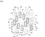
- FIG. 2 is a diagram for explaining the arrangement of the transmitting antenna and the receiving antenna
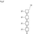
- FIG. 3 is a diagram showing an example of an element antenna
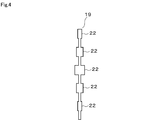
- FIG. 4 is a diagram showing another example of the element antenna
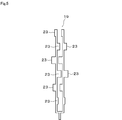
- FIG. 5 is a diagram showing another example of the element antenna
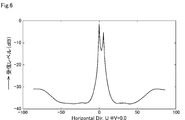
- FIG. 6 is a characteristic diagram showing the horizontal detection range and detection level of the receiving antenna
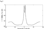
- FIG. 7 is a characteristic diagram showing the detection range and the detection level of the receiving antenna in the vertical direction
- FIG. 8 shows the second embodiment and is a diagram for explaining the arrangement of the transmitting antenna and the receiving antenna.
- FIG. 1 is a functional block diagram of the radar device according to the first embodiment
- FIG. 2 is a diagram for explaining the arrangement of the transmitting antenna and the receiving antenna
- FIG. 3 is a diagram showing an example of an element antenna
- FIG. 4 is a diagram showing another example of the element antenna
- FIG. 5 is a diagram showing another example of the element antenna
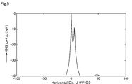
- FIG. 9 is a characteristic diagram showing the horizontal detection range and detection level of the receiving antenna
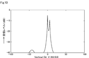
- FIG. 10 is a characteristic diagram showing the detection range and the detection level of the receiving antenna in the vertical direction
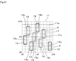
- FIG. 11 shows the third embodiment and is a diagram for explaining the arrangement of the transmitting antennas and the receiving antennas.
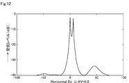
- FIG. 12 is a characteristic diagram showing the horizontal detection range and detection level of the receiving antenna
- FIG. 13 is a characteristic diagram showing the detection range and the detection level of the receiving antenna in the vertical direction
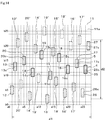
- FIG. 14 shows the fourth embodiment and is a diagram for explaining the arrangement of the transmitting antenna and the receiving antenna.
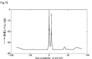
- FIG. 15 is a characteristic diagram showing the horizontal detection range and detection level of the receiving antenna
- FIG. 16 is a characteristic diagram showing the detection range and the detection level of the receiving antenna in the vertical direction
- FIG. 15 is a characteristic diagram showing the horizontal detection range and detection level of the receiving antenna
- FIG. 16 is a characteristic diagram showing the detection range and the detection level of the receiving antenna in the vertical direction
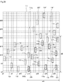
- FIG. 17 shows the fifth embodiment and is a diagram for explaining the arrangement of the transmitting antenna and the receiving antenna.
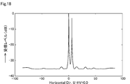
- FIG. 18 is a characteristic diagram showing the horizontal detection range and detection level of the receiving antenna
- FIG. 19 is a characteristic diagram showing the detection range and the detection level of the receiving antenna in the vertical direction
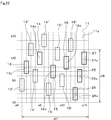
- FIG. 20 shows the sixth embodiment and is a diagram for explaining the arrangement of the transmitting antennas and the receiving antennas.
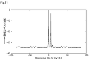
- FIG. 21 is a characteristic diagram showing the horizontal detection range and detection level of the receiving antenna.
- FIG. 22 is a characteristic diagram showing the detection range and the detection level of the receiving antenna in the vertical direction
- FIG. 23 shows the seventh embodiment and is a diagram for explaining the arrangement of the transmitting antenna and the receiving antenna.
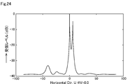
- FIG. 24 is a characteristic diagram showing the horizontal detection range and detection level of the receiving antenna
- FIG. 25 is a characteristic diagram showing the vertical detection range and detection level of the receiving antenna.
- the radar device 1 of the present embodiment is, for example, a vehicle radar device mounted on a vehicle. As shown in FIG. 1, the radar device 1 includes a signal generator 2, a transmitter 3, a transmitter antenna 4, a receiver antenna 5, a receiver 6, a signal processor 7, a controller 8, and a power supply. And a part 9.
- the signal generator 2 generates and outputs a reference signal for generating radio waves for radar.
- the signal generator 2 generates, for example, a reference signal having an FCM (Fast Chirp Modulation) waveform in which the frequency changes like a sawtooth wave.
- the transmitter 3 receives the reference signal from the signal generator 2, generates a radio wave for radar based on the input reference signal, and sends it out from the transmission antenna 4.
- the transmission unit 3 converts the reference signal output from the signal generation unit 2 into a signal having a frequency range and power specified by the Radio Law and outputs the signal.
- the transmitting antenna 4 receives the signal converted by the transmitting unit 3 and emits a radar electric wave having a desired power distribution in a desired radiation range.
- the receiving antenna 5 receives the reflected electric wave reflected by the target such as an obstacle or an object in front of the vehicle.
- the receiving unit 6 receives the received signal from the receiving antenna 5 and the reference signal from the signal generating unit 2, and generates a signal for calculating the position and speed of the target based on the input signals.
- the signal processing unit 7 inputs the signal from the receiving unit 6 and performs signal processing based on the input signal to calculate the position of the target.
- the control unit 8 has a function of controlling on / off of transmission of radar transmission radio waves, control of modulation and the like, and a function of transmitting a signal calculated by the signal processing unit 7 to an external device.
- the power supply unit 9 shares the power supply required for each unit of the radar device 1.
- the received radio wave of the radar device 1, that is, the reflected radio wave reflected by the target may be regarded as a plane wave. Then, in order to estimate the arrival direction of the plane wave that is the received radio wave, it is only necessary to obtain the normal vector of the plane or two or more linearly independent vectors forming the plane. Focusing on this, in the present embodiment, three or more receiving antennas are provided, and for these three or more receiving antennas, two or more direction vectors configured with one of them as a reference are primary independent. With this configuration, the arrival direction of the received radio wave can be estimated not only in the horizontal direction but also in the vertical direction.
- the transmitting antenna 4 and the receiving antenna 5 are arranged on a single substrate 11.
- the substrate 11 is used upright and arranged so that the plane of the substrate 11, that is, the plane shown in FIG. 2, faces the front of the vehicle as the front surface 11a.
- the arrow A direction corresponds to the first direction, for example, the horizontal direction, that is, the left-right direction
- the arrow B direction is perpendicular to the first direction. It corresponds to the two directions, for example, the vertical direction, that is, the vertical direction.
- the transmission antenna 4 having one element antenna 12 is disposed in, for example, the lower right corner of the front surface 11a of the substrate 11, and a plurality of, for example, eight element antennas 13 to 20 are provided in other regions of the front surface 11a of the substrate 11.
- the receiving antenna 5 having is provided.
- the element antennas 12 to 20 have, for example, the same configuration and have a plurality of patch antennas. As shown in FIG. 3, an example of a specific configuration of each of the element antennas 12 to 20 is configured by connecting, for example, four square patch antennas 21 in series in one row, for example.
- the number of patch antennas 21 is not limited to four, and may be 5 or more, or 3 or less depending on a desired detection distance, angle range, and the like.
- serial connection is shown here, parallel connection may be used.
- FIGS. 4 and 5 show other examples of the element antennas 12 to 20.
- five patch antennas 22 having different shapes and sizes are arranged in an array.
- six patch antennas 23 connected in series in one row are arranged in two rows, and one end is connected.
- the shape and size of such patch antenna arrays 22 and 23 are determined in the process of optimizing the radiation pattern of the radio waves from the antennas.
- a plurality of patch antennas connected in series in one row may be arranged in three or more rows depending on a desired detection distance and angle range.
- the lower left corner of the substrate 11 is set as the origin (a0, b0), and (a1, b0), (a2, b0), (a3, b0) ... in the right direction and (a0, b1), ( A0, b2), (a0, b3) ...
- the coordinates in the horizontal direction A and the vertical direction B are set.
- the vertical and horizontal intervals of the grid indicated by broken lines are set to, for example, half the wavelength ⁇ of the radio wave for radar.
- the vertical and horizontal intervals of the grating may be set to an appropriate length different from half the wavelength ⁇ .
- the center 12c of the element antenna 12 which is the transmitting antenna 4 is arranged at the coordinates (a10, b2).
- the center 13c of the first element antenna 13 is arranged at coordinates (a1, b5), and the center 14c of the second element antenna 14 is arranged at coordinates. It is arranged at (a3, b3), the center 15c of the third element antenna 15 is arranged at coordinates (a5, b2), and the center 16c of the fourth element antenna 16 is arranged at coordinates (a7, b4).
- the center 17c of the fifth element antenna 17 is arranged at the coordinates (a8, b7), the center 18c of the sixth element antenna 18 is arranged at the coordinates (a6, b8), and the seventh element antenna 19 is arranged.
- Center 19c of the eighth element antenna 20 is arranged at coordinates (a4, b9), and the center 20c of the eighth element antenna 20 is arranged at coordinates (a2, b7).
- the eight element antennas 13 to 20 of the receiving antenna 5 are arranged in the first direction, for example, in the horizontal direction, that is, , The horizontal direction, and the second direction perpendicular to the first direction, for example, the vertical direction, that is, the vertical direction, that is, the vertical direction, that is, the vertical direction. Further, among the eight element antennas 13 to 20, the two adjacent element antennas are arranged so that the horizontal distance between them is equal, and the two adjacent element antennas are arranged so that the vertical distance between them is also equal. ing.
- the arrangement form of the eight element antennas 13 to 20 is configured so as to be a substantially circular arrangement form. Further, the arrangement form of the eight element antennas 13 to 20 is configured to be point-symmetrical.
- FIG. 6 and 7 show the result of simulating the receiving operation of the receiving antenna 5 of the radar device 1 of the present embodiment.
- targets are placed at the origins (0, 0) in the horizontal and vertical directions, at the positions of (6.0 °, 0), and at the positions of (0, 6.0 °), and reflected by each target.
- the received signal when the received radio wave was received by the receiving antenna 5 of this embodiment was examined.
- FIG. 6 is a characteristic diagram showing the horizontal detection range and detection level of the receiving antenna 5 of the present embodiment, that is, the reception level.
- FIG. 7 is a characteristic diagram showing the vertical detection range and detection level of the receiving antenna 5 of this embodiment. From these FIG. 6 and FIG.
- the receiving antenna 5 of the radar device 1 of the present embodiment has a detection resolution equivalent to that in the horizontal direction even in the vertical direction. Further, according to the present embodiment, it is possible to increase the degree of freedom in the shape of the antenna, and it is possible to use the antenna array according to the desired gain and detection range. Therefore, the resolution and the detection distance / range can be compatible.
- (Second embodiment) 8 to 10 show the second embodiment.
- the same components as those in the first embodiment are designated by the same reference numerals.
- the arrangement form of the eight element antennas 13 to 20 of the receiving antenna 5 is configured to be close to a pseudo-random arrangement form.
- the center 13c of the first element antenna 13 is arranged at coordinates (a1, b7), and the center 14c of the second element antenna 14 is arranged at coordinates. It is arranged at (a2, b4), the center 15c of the third element antenna 15 is arranged at coordinates (a4, b3), and the center 16c of the fourth element antenna 16 is arranged at coordinates (a7, b2). ing. Then, the center 17c of the fifth element antenna 17 is arranged at the coordinates (a8, b5), the center 18c of the sixth element antenna 18 is arranged at the coordinates (a6, b8), and the seventh element antenna 19 is arranged. Center 19c of the eighth element antenna 20 is arranged at coordinates (a5, b6), and the center 20c of the eighth element antenna 20 is arranged at coordinates (a3, b9).
- the arrangement form of the eight element antennas 13 to 20 becomes close to a pseudo random arrangement form. ..
- the eight element antennas 13 to 20 two element antennas adjacent to each other in the vertical direction are arranged so as to face each other with a straight line extending in the left-right direction passing through an intermediate position in the vertical direction, for example, the position b5 interposed therebetween.
- the element antennas 13 to 20 are arranged such that the signs of the coordinates in the vertical direction with respect to the vertical middle point, for example, the position b5, alternate.
- the configuration of the second embodiment other than the above is the same as the configuration of the first embodiment. Therefore, also in the second embodiment, it is possible to obtain substantially the same operational effects as the first embodiment.
- FIGS. 9 and 10 The results of simulating the reception operation of the reception antenna 5 of the radar device 1 of the second embodiment are shown in FIGS. 9 and 10.
- the simulation conditions are the same as in the first embodiment.
- FIG. 9 is a characteristic diagram showing the horizontal detection range and detection level of the receiving antenna 5 of the second embodiment.
- FIG. 10 is a characteristic diagram showing the vertical detection range and the detection level of the receiving antenna 5 of the second embodiment. From these FIG. 9 and FIG. 10, it can be confirmed that the receiving antenna 5 of the radar device 1 of the second embodiment has a detection resolution equivalent to that in the horizontal direction even in the vertical direction.
- FIG. 11 shows the third embodiment.
- the same components as those in the first embodiment are designated by the same reference numerals.
- the arrangement form of the seven element antennas 13 to 19 of the receiving antenna 5 is configured so as to be close to the arrangement form of the approximately circular shape and its center position.
- the center 13c of the first element antenna 13 is arranged at coordinates (a1, b4) and the center 14c of the second element antenna 14 is arranged at coordinates. It is arranged at (a3, b2), the center 15c of the third element antenna 15 is arranged at coordinates (a4, b5), and the center 16c of the fourth element antenna 16 is arranged at coordinates (a6, b3).
- the center 17c of the fifth element antenna 17 is arranged at the coordinates (a7, b6), the center 18c of the sixth element antenna 18 is arranged at the coordinates (a5, b8), and the seventh element antenna 19 is arranged.
- the center 19c of is located at coordinates (a2, b7).
- the arrangement form of the seven element antennas 13 to 20 is approximately circular and its center position is arranged. Get closer to form.
- the configuration of the third embodiment other than the above is the same as the configuration of the first embodiment. Therefore, also in the third embodiment, it is possible to obtain substantially the same operational effects as in the first embodiment.
- FIGS. 12 and 13 Results of simulating the receiving operation of the receiving antenna 5 of the radar device 1 of the third embodiment are shown in FIGS. 12 and 13.
- the simulation conditions are the same as in the first embodiment.
- FIG. 12 is a characteristic diagram showing the horizontal detection range and detection level of the receiving antenna 5 of the third embodiment.
- FIG. 13 is a characteristic diagram showing the vertical detection range and detection level of the receiving antenna 5 of the third embodiment. From these FIG. 12 and FIG. 13, it can be confirmed that the receiving antenna 5 of the radar device 1 according to the third embodiment has the same detection resolution in the vertical direction as in the horizontal direction.
- (Fourth Embodiment) 14 to 16 show the fourth embodiment.
- the same components as those in the first embodiment are designated by the same reference numerals.
- the arrangement form of the eight element antennas 13 to 20 of the receiving antenna 5 is configured so as to be close to a substantially circular shape, for example, an oval shape that is horizontally long in the horizontal direction. ..
- the transmitting antenna 4 three element antennas 25, 26, 27 are provided.
- the center 13c of the first element antenna 13 is arranged at the coordinates (a2, b13), and the center 14c of the second element antenna 14 is arranged at the coordinates (a2, b13). It is arranged at (a8, b11), the center 15c of the third element antenna 15 is arranged at coordinates (a14, b10), and the center 16c of the fourth element antenna 16 is arranged at coordinates (a20, b12).
- the center 17c of the fifth element antenna 17 is arranged at coordinates (a23, b14), the center 18c of the sixth element antenna 18 is arranged at coordinates (a17, b16), and the seventh element antenna 19 is arranged.
- Center 19c of the eighth element antenna 20 is arranged at coordinates (a11, b17), and the center 20c of the eighth element antenna 20 is arranged at coordinates (a5, b15).
- the center 25c of the first element antenna 25 is arranged at the coordinates (a26, b12) and the center 26c of the second element antenna 26 is arranged.
- the center 27c of the third element antenna 27 is arranged at coordinates (a27, b20).
- the eight antenna elements 13 to 20 of the reception antenna 5 receive the radio waves reflected by the target of the radio waves transmitted from the second element antenna 26 of the transmission antenna 4 to receive the reception antenna 5
- the receiving function is realized by the virtual eight element antennas 13 'to 20'.
- the radio wave reflected by the target of the radio wave transmitted from the third element antenna 27 of the transmitting antenna 4 is received by the eight element antennas 13 to 20 of the receiving antenna 5, and the virtual antenna of the receiving antenna 5 is received.
- the reception function is realized by the eight element antennas 13 "to 20".
- the receiving antenna 5 is actually provided with only eight element antennas 13 to 20, but the virtual eight element antennas 13 ′ to 20 ′ and the virtual eight element antennas 13 ′ to 20 ′.
- the configuration is provided with individual element antennas 13 "to 20".
- the antenna substrate 11 As the antenna substrate 11, a substrate in a region surrounded by the horizontal dimension d1 and the vertical dimension d2 in FIG. 14 is prepared, and the eight antennas of the receiving antenna 5 are provided on the substrate.
- the element antennas 13 to 20 and the three element antennas 25, 26 and 27 of the transmission antenna 4 may be formed.
- the arrangement form of the eight element antennas 13 to 20 is approximately circular, for example, horizontally long in the horizontal direction. It is close to an elliptical arrangement.
- M element antennas of the receiving antenna 5 are set.
- the horizontal interval of 13 to 20 is approximately N / 2 times the wavelength ⁇
- the vertical interval of the M element antennas 13 to 20 of the receiving antenna 5 is approximately 1/2 of the wavelength ⁇ .
- the horizontal spacing of the N element antennas 25 to 27 of the transmitting antenna 4 is about 1/2 times the wavelength ⁇ , and the vertical direction of the N element antennas 25 to 27 of the transmitting antenna 4 is increased. Is about M / 2 times the wavelength ⁇ .
- the interval of the M element antennas of the receiving antenna in the first direction is N times the first set interval d1
- the second direction of the M element antennas of the receiving antenna is Is the second set interval d2
- the N element antennas of the transmitting antenna in the first direction is the first set interval d1
- the N element antennas of the transmitting antenna are in the second direction. Is configured to be M times the second set interval d2.
- the configuration of the fourth embodiment other than the above is the same as the configuration of the first embodiment. Therefore, also in the fourth embodiment, it is possible to obtain substantially the same operational effects as in the first embodiment.
- FIG. 15 and 16 show the result of simulating the receiving operation of the receiving antenna 5 of the radar device 1 of the fourth embodiment.
- the simulation conditions are the same as in the first embodiment.
- FIG. 15 is a characteristic diagram showing the horizontal detection range and detection level of the receiving antenna 5 of the fourth embodiment.
- FIG. 16 is a characteristic diagram showing the vertical detection range and detection level of the receiving antenna 5 of the fourth embodiment. From these FIG. 15 and FIG. 16, it can be confirmed that the receiving antenna 5 of the radar device 1 of the fourth embodiment has a detection resolution equivalent to that in the horizontal direction even in the vertical direction.
- (Fifth Embodiment) 17 to 19 show the fifth embodiment.
- the same components as those in the fourth embodiment are designated by the same reference numerals.
- the arrangement form of the eight element antennas 13 to 20 of the receiving antenna 5 is configured so as to be close to a substantially circular shape, for example, an elliptical shape that is horizontally long in the vertical direction. ..
- the center 13c of the first element antenna 13 is arranged at the coordinates (a9, b12), and the center 14c of the second element antenna 14 is arranged at the coordinates (a9, b12). It is arranged at (a11, b7), the center 15c of the third element antenna 15 is arranged at coordinates (a13, b4), and the center 16c of the fourth element antenna 16 is arranged at coordinates (a15, b10).
- the center 17c of the fifth element antenna 17 is arranged at the coordinates (a16, b16), the center 18c of the sixth element antenna 18 is arranged at the coordinates (a14, b22), and the seventh element antenna 19 is arranged.
- the center 19c of the eighth element antenna 20 is arranged at the coordinates (a12, b25), and the center 20c of the eighth element antenna 20 is arranged at the coordinates (a10, b19).
- the center 25c of the first element antenna 25 is arranged at the coordinates (a15, b3) and the center 26c of the second element antenna 26 is arranged.
- the center 27c of the third element antenna 27 is arranged at coordinates (a23, b2).
- the eight antenna elements 13 to 20 of the reception antenna 5 receive the radio waves reflected by the target of the radio waves transmitted from the second element antenna 26 of the transmission antenna 4 to receive the reception antenna 5
- the receiving function is realized by the virtual eight element antennas 13 'to 20'.
- the radio wave reflected by the target of the radio wave transmitted from the third element antenna 27 of the transmitting antenna 4 is received by the eight element antennas 13 to 20 of the receiving antenna 5, and the virtual antenna of the receiving antenna 5 is received.
- the reception function is realized by the eight element antennas 13 "to 20".
- the receiving antenna 5 is actually provided with only eight element antennas 13 to 20, but the virtual eight element antennas 13 ′ to 20 ′ and the virtual eight element antennas 13 ′ to 20 ′.
- the configuration is provided with individual element antennas 13 "to 20".
- the antenna substrate 11 a substrate in a region surrounded by the horizontal dimension d3 and the vertical dimension d4 in FIG. 17 is prepared, and eight elements of the substance of the receiving antenna 5 are provided on the substrate.
- the antennas 13 to 20 and the three element antennas 25, 26, 27 of the transmitting antenna 4 may be formed.
- the arrangement form of the eight element antennas 13 to 20 is approximately circular, for example, horizontally long in the vertical direction. It is close to an elliptical arrangement.
- M element antennas of the receiving antenna 5 are set.
- the horizontal spacing of 13 to 20 is approximately 1/2 the wavelength
- the vertical spacing of the M element antennas 13 to 20 of the receiving antenna 5 is approximately N / 2 times the wavelength.
- the horizontal spacing of the N element antennas 25 to 27 of the transmitting antenna 4 is approximately M / 2 times the wavelength, and the vertical spacing of the N element antennas 25 to 27 of the transmitting antenna 4 is approximately. It is configured to have a length that is 1/2 times the wavelength.
- the interval between the M element antennas of the receiving antenna in the first direction is the first set interval d1
- the interval between the M element antennas of the receiving antenna in the second direction is.
- the second set interval d2 is N times
- the interval of the N element antennas of the transmitting antenna in the first direction is M times the first set interval d1
- the second element interval of the N element antennas of the transmitting antenna is The distance in the direction is configured to be the second set distance d2.
- the configuration of the fifth embodiment other than the above is the same as the configuration of the fourth embodiment. Therefore, also in the fifth embodiment, it is possible to obtain substantially the same operational effects as the fourth embodiment.
- FIG. 18 and 19 show the result of simulating the receiving operation of the receiving antenna 5 of the radar device 1 of the fifth embodiment.
- the simulation conditions are the same as in the first embodiment.
- FIG. 18 is a characteristic diagram showing the horizontal detection range and detection level of the receiving antenna 5 of the fifth embodiment.
- FIG. 19 is a characteristic diagram showing the vertical detection range and detection level of the receiving antenna 5 of the fifth embodiment. From these FIG. 18 and FIG. 19, it can be confirmed that the receiving antenna 5 of the radar device 1 according to the fifth embodiment has the same detection resolution in the vertical direction as in the horizontal direction.
- FIG. 20 to 22 show the sixth embodiment.
- the same components as those in the first embodiment are designated by the same reference numerals.
- the arrangement form of the eight element antennas 13 to 20 of the receiving antenna 5 is configured to be close to a substantially circular arrangement form.
- the transmitting antenna 4 is provided with three element antennas 25, 26 and 27.
- the center 13c of the first element antenna 13 is arranged at the coordinates (a17, b9) and the center of the second element antenna 14 is arranged.
- 14c is arranged at coordinates (a21, b5)
- the center 15c of the third element antenna 15 is arranged at coordinates (a25, b3)
- the center 16c of the fourth element antenna 16 is arranged at coordinates (a29, b7).
- the center 17c of the fifth element antenna 17 is arranged at the coordinates (a31, b11)
- the center 18c of the sixth element antenna 18 is arranged at the coordinates (a27, b15)
- the seventh element antenna 19 is arranged.
- the center 19c of the eighth element antenna 20 is arranged at the coordinates (a23, b17), and the center 20c of the eighth element antenna 20 is arranged at the coordinates (a19, b13).
- the center 25c of the first element antenna 25 is arranged at the coordinates (a31, b3), and the center 26c of the second element antenna 26 is arranged.
- the center 27c of the third element antenna 27 is arranged at coordinates (a32, b19).
- the eight antenna elements 13 to 20 of the reception antenna 5 receive the radio waves reflected by the target of the radio waves transmitted from the second element antenna 26 of the transmission antenna 4 to receive the reception antenna 5
- the receiving function is realized by the virtual eight element antennas 13 'to 20'.
- the radio wave reflected by the target of the radio wave transmitted from the third element antenna 27 of the transmitting antenna 4 is received by the eight element antennas 13 to 20 of the receiving antenna 5, and the virtual antenna of the receiving antenna 5 is received.
- the reception function is realized by the eight element antennas 13 "to 20".
- the receiving antenna 5 is actually provided with only eight element antennas 13 to 20, but the virtual eight element antennas 13 ′ to 20 ′ and the virtual eight element antennas 13 ′ to 20 ′.
- the configuration is provided with individual element antennas 13 "to 20".
- the antenna substrate 11 As the antenna substrate 11, a substrate in a region surrounded by the horizontal dimension d5 and the vertical dimension d6 in FIG. 20 is prepared, and the eight antennas of the receiving antenna 5 are provided on the substrate.
- the element antennas 13 to 20 and the three element antennas 25, 26 and 27 of the transmission antenna 4 may be formed.
- the disposition form of the eight element antennas 13 to 20 becomes close to a substantially circular disposition form.
- the receiving antenna 5 includes substantially eight element antennas 13 to 20, virtual eight element antennas 13 ′ to 20 ′, and virtual eight element antennas 13 ′′ to 20 ′′, which are substantially L. A configuration arranged in a letter shape has been realized.
- the first antenna of the transmitting antenna 4 is used.
- the second element antenna 26 has a horizontal interval approximately equal to 1/2 of the wavelength ⁇ , and a vertical interval of approximately M / 2 times the wavelength ⁇ .
- the horizontal spacing is approximately M / 2 times the wavelength ⁇
- the vertical spacing is approximately half the wavelength ⁇ . Is configured to be.
- the horizontal spacing between the M element antennas 13 to 20 of the receiving antenna 5 is approximately equal to 1/2 of the wavelength ⁇
- the vertical spacing between the M element antennas 13 to 20 of the receiving antenna 5 is approximately. It is configured to be equal to 1 ⁇ 2 of the wavelength ⁇ .
- the second element antenna has the same interval in the first direction as the first set interval d1 and The interval in the second direction is M times the second set interval d2, and the third element antenna has the interval in the first direction that is M times the first set interval d1 and the interval in the second direction.
- the second set interval d2 is set, the interval between the M element antennas of the receiving antenna in the first direction is twice the first set interval d1, and the interval between the M element antennas of the receiving antenna in the second direction. Is configured to be twice the second set interval d2.
- the configuration of the sixth embodiment other than the above is the same as the configuration of the first embodiment. Therefore, also in the sixth embodiment, it is possible to obtain substantially the same operational effects as in the first embodiment.
- FIG. 21 and 22 show the result of simulating the receiving operation of the receiving antenna 5 of the radar device 1 of the sixth embodiment.
- the simulation conditions are the same as in the first embodiment.
- FIG. 21 is a characteristic diagram showing the horizontal detection range and detection level of the receiving antenna 5 of the sixth embodiment.
- FIG. 22 is a characteristic diagram showing the vertical detection range and detection level of the receiving antenna 5 of the sixth embodiment. From these FIG. 21 and FIG. 22, it can be confirmed that the receiving antenna 5 of the radar device 1 according to the sixth embodiment has the same detection resolution in the vertical direction as in the horizontal direction. Furthermore, it can be seen that the receiving antenna 5 in which the element antennas are arranged in an L shape can have high detection resolution, that is, high resolution.
- (Seventh embodiment) 23 to 25 show the seventh embodiment.
- the same components as those in the first embodiment are designated by the same reference numerals.
- the four element antennas 13 to 16 of the receiving antenna 5 are arranged in a so-called zigzag pattern, that is, in a staggered pattern.
- the center 13c of the first element antenna 13 is arranged at coordinates (a2, b8), and the center 14c of the second element antenna 14 is arranged at coordinates. It is arranged at (a5, b10), the center 15c of the third element antenna 15 is arranged at coordinates (a8, b7), and the center 16c of the fourth element antenna 16 is arranged at coordinates (a11, b9). ing.
- the center 25c of the first element antenna 25 is arranged at the coordinates (a14, b6) and the center 26c of the second element antenna 26 is arranged.
- the center 27c of the third element antenna 27 is arranged at coordinates (a15, b10).
- the four antenna elements 13 to 16 of the reception antenna 5 receive the radio waves reflected by the target of the radio waves transmitted from the second element antenna 26 of the transmission antenna 4 to receive the reception antenna 5
- the function of receiving is realized by the virtual four element antennas 13 'to 16'.
- the four element antennas 13 to 16 of the reception antenna 5 receive the radio waves reflected by the target of the radio waves transmitted from the third element antenna 27 of the transmission antenna 4 to generate a virtual image of the reception antenna 5.
- the function of receiving is realized by the four element antennas 13 "to 16".
- the receiving antenna 5 is actually provided with only four element antennas 13 to 16, but the virtual four element antennas 13 ′ to 16 ′ and the virtual four element antennas 13 ′ to 16 ′.
- the configuration is provided with individual element antennas 13 "to 16".
- the antenna substrate 11 a substrate in a region surrounded by the horizontal dimension d7 and the vertical dimension d8 in FIG. 23 is prepared, and the four elements of the substance of the receiving antenna 5 are provided on the substrate.
- the antennas 13 to 16 and the three element antennas 25, 26 and 27 of the transmitting antenna 4 may be formed.
- the configuration of the seventh embodiment other than the above is the same as the configuration of the first embodiment. Therefore, also in the seventh embodiment, it is possible to obtain substantially the same operational effects as in the first embodiment.
- FIG. 24 and 25 show the result of simulating the receiving operation of the receiving antenna 5 of the radar device 1 of the seventh embodiment.
- the simulation conditions are the same as in the first embodiment.
- FIG. 24 is a characteristic diagram showing the horizontal detection range and detection level of the receiving antenna 5 of the seventh embodiment.
- FIG. 25 is a characteristic diagram showing the vertical detection range and detection level of the receiving antenna 5 of the seventh embodiment. From these FIG. 24 and FIG. 25, it can be confirmed that the receiving antenna 5 of the radar device 1 of the seventh embodiment has the same detection resolution in the vertical direction as in the horizontal direction.
Landscapes
- Engineering & Computer Science (AREA)
- Radar, Positioning & Navigation (AREA)
- Remote Sensing (AREA)
- Physics & Mathematics (AREA)
- Computer Networks & Wireless Communication (AREA)
- General Physics & Mathematics (AREA)
- Computer Security & Cryptography (AREA)
- Electromagnetism (AREA)
- Radar Systems Or Details Thereof (AREA)
- Variable-Direction Aerials And Aerial Arrays (AREA)
- Waveguide Aerials (AREA)
Abstract
本実施形態のレーダ装置は、少なくとも1個の素子アンテナ12を有する送信アンテナ4と、複数の素子アンテナ13-20を有する受信アンテナ5とを備えたものであって、受信アンテナの複数の素子アンテナは、第1の方向及び第1の方向に対して垂直な第2の方向に互いに異なる位置に配置され、受信アンテナの複数の素子アンテナのうちの、隣接する2個の素子アンテナの第1の方向の間隔が等しくなると共に、隣接する2個の素子アンテナの第2の方向の間隔が等しくなるように配置されたものである。
Description
本出願は、2018年11月19日に出願された日本出願番号2018-216492号に基づくもので、ここにその記載内容を援用する。
本開示は、レーダ装置に関する。
車両用のレーダ装置は、車両の前方の他車両等の物体を検知するために、水平方向、即ち、左右方向の検知機能を必要としていることから、受信アンテナを水平方向に等間隔に多数配置していた。これにより、水平方向の必要な検知分解能を得ていた。近年は、車両用のレーダ装置として、垂直方向、即ち、上下方向の検知機能も要求されてきている。特に、交差点の状況を監視する用途や、車両以外の移動体例えばドローン等に搭載する用途においては、垂直方向についても、水平方向と同等の検知範囲及び検知分解能が求められている。
従来の車両用のレーダ装置においては、垂直方向に、2、3組の受信アンテナを配置する構成のものがある(例えば特許文献1参照)。この構成では、垂直方向についても、1個の物体の角度を検知することはできるが、2個以上の物体が存在する場合には、十分に検知することができないという問題があった。
また、特許文献2では、複数の送信・受信アンテナの配置を水平・垂直のさまざまな位置に配置することにより、垂直方向の分離能を得ることができている。この構成では、いずれかのアンテナを垂直方向にも電波の波長λの1/2程度の間隔で配置されることが要求されている。そのため、図3に示すような多数のパッチアンテナを接続してアンテナ利得を高めるような使用方法がとれない。また、上記構成では、水平方向も同様に電波の波長λの1/2程度の間隔で配置されることが要求されている。そのため、図5に示すような並列接続して利得を高めるようなことができない。
本開示の目的は、垂直方向についても、水平方向と同等の検知範囲及び検知分解能を得ることができ、また、アンテナ形状の自由度を高め、所望の利得、検知範囲に応じたアンテナアレーを用いることを可能とすることで、分解能と検知距離・範囲が両立できるレーダ装置を提供することにある。
また、特許文献2では、複数の送信・受信アンテナの配置を水平・垂直のさまざまな位置に配置することにより、垂直方向の分離能を得ることができている。この構成では、いずれかのアンテナを垂直方向にも電波の波長λの1/2程度の間隔で配置されることが要求されている。そのため、図3に示すような多数のパッチアンテナを接続してアンテナ利得を高めるような使用方法がとれない。また、上記構成では、水平方向も同様に電波の波長λの1/2程度の間隔で配置されることが要求されている。そのため、図5に示すような並列接続して利得を高めるようなことができない。
本開示の目的は、垂直方向についても、水平方向と同等の検知範囲及び検知分解能を得ることができ、また、アンテナ形状の自由度を高め、所望の利得、検知範囲に応じたアンテナアレーを用いることを可能とすることで、分解能と検知距離・範囲が両立できるレーダ装置を提供することにある。
本開示の一態様において、レーダ装置は、少なくとも1個の素子アンテナを有する送信アンテナと、複数の素子アンテナを有する受信アンテナとを備えたレーダ装置であって、前記受信アンテナの複数の素子アンテナは、第1の方向及び第1の方向に対して垂直な第2の方向に互いに異なる位置に配置され、前記受信アンテナの複数の素子アンテナのうちの、隣接する2個の素子アンテナの第1の方向の間隔が等しくなると共に、隣接する2個の素子アンテナの第2の方向の間隔が等しくなるように配置されたものである。
本開示についての上記目的およびその他の目的、特徴や利点は、添付の図面を参照しながら下記の詳細な記述により、より明確になる。その図面は、
図1は、第1実施形態を示すレーダ装置の機能ブロック図であり、
図2は、送信アンテナ及び受信アンテナの配置形態を説明する図であり、
図3は、素子アンテナの一例を示す図であり、
図4は、素子アンテナの他の例を示す図であり、
図5は、素子アンテナの他の例を示す図であり、
図6は、受信アンテナの水平方向の検知範囲及び検知レベルを示す特性図であり、
図7は、受信アンテナの垂直方向の検知範囲及び検知レベルを示す特性図であり、
図8は、第2実施形態を示すもので、送信アンテナ及び受信アンテナの配置形態を説明する図であり、
図9は、受信アンテナの水平方向の検知範囲及び検知レベルを示す特性図であり、
図10は、受信アンテナの垂直方向の検知範囲及び検知レベルを示す特性図であり、
図11は、第3実施形態を示すもので、送信アンテナ及び受信アンテナの配置形態を説明する図であり、
図12は、受信アンテナの水平方向の検知範囲及び検知レベルを示す特性図であり、
図13は、受信アンテナの垂直方向の検知範囲及び検知レベルを示す特性図であり、
図14は、第4実施形態を示すもので、送信アンテナ及び受信アンテナの配置形態を説明する図であり、
図15は、受信アンテナの水平方向の検知範囲及び検知レベルを示す特性図であり、
図16は、受信アンテナの垂直方向の検知範囲及び検知レベルを示す特性図であり、
図17は、第5実施形態を示すもので、送信アンテナ及び受信アンテナの配置形態を説明する図であり、
図18は、受信アンテナの水平方向の検知範囲及び検知レベルを示す特性図であり、
図19は、受信アンテナの垂直方向の検知範囲及び検知レベルを示す特性図であり、
図20は、第6実施形態を示すもので、送信アンテナ及び受信アンテナの配置形態を説明する図であり、
図21は、受信アンテナの水平方向の検知範囲及び検知レベルを示す特性図であり、
図22は、受信アンテナの垂直方向の検知範囲及び検知レベルを示す特性図であり、
図23は、第7実施形態を示すもので、送信アンテナ及び受信アンテナの配置形態を説明する図であり、
図24は、受信アンテナの水平方向の検知範囲及び検知レベルを示す特性図であり、
図25は、受信アンテナの垂直方向の検知範囲及び検知レベルを示す特性図である。
(第1実施形態)
以下、第1実施形態について、図1ないし図7を参照して説明する。本実施形態のレーダ装置1は、例えば車両に搭載される車両用のレーダ装置である。レーダ装置1は、図1に示すように、信号発生部2と、送信部3と、送信アンテナ4と、受信アンテナ5と、受信部6と、信号処理部7と、制御部8と、電源部9とを備えている。
以下、第1実施形態について、図1ないし図7を参照して説明する。本実施形態のレーダ装置1は、例えば車両に搭載される車両用のレーダ装置である。レーダ装置1は、図1に示すように、信号発生部2と、送信部3と、送信アンテナ4と、受信アンテナ5と、受信部6と、信号処理部7と、制御部8と、電源部9とを備えている。
信号発生部2は、レーダ用の電波を生成するための基準信号を生成して出力する。信号発生部2は、例えば周波数がのこぎり波状に変化するFCM(Fast Chirp Modulation)波形の基準信号を生成する。送信部3は、信号発生部2からの基準信号を入力し、入力した基準信号に基づいてレーダ用の電波を生成し、送信アンテナ4から送出する。送信部3では、信号発生部2から出力された基準信号を電波法で規定される周波数範囲及び電力の信号に変換して出力する。送信アンテナ4は、送信部3で変換された信号を入力し、所望の放射範囲において所望の電力分布となるレーダ用の電波を発射する。
受信アンテナ5は、車両の前方の障害物や物体等のターゲットで反射した反射電波を受信する。受信部6は、受信アンテナ5からの受信信号と、信号発生部2からの基準信号とを入力し、これら入力した信号に基づいてターゲットの位置や速度等を計算するための信号を生成する。
信号処理部7は、受信部6からの信号を入力し、入力した信号に基づいて信号処理を行ってターゲットの位置を計算する。制御部8は、レーダ送信電波の送信のオン・オフや、変調等の制御を行う機能と、信号処理部7で計算された信号を外部の機器へ送信する機能とを有する。電源部9は、レーダ装置1の各部に必要な電源を共有する。
本実施形態においては、レーダ装置1の受信電波、即ち、ターゲットで反射した反射電波は平面波として見なしてもよい。そして、受信電波である平面波の到来方向を推定するためには、その平面の法線ベクトル或いは平面を構成する2つ以上の一次独立なベクトルを求めればよい。このことに着目し、本実施形態では、受信アンテナを3つ以上備え、これら3つ以上の受信アンテナについて、その内の1つを基準として構成される方向ベクトルが2つ以上一次独立となるように構成することにより、受信電波の到来方向を水平方向だけでなく、垂直方向にも推定できるように構成した。
ここで、送信アンテナ4及び受信アンテナ5の一例について、図2及び図3を参照して説明する。本実施形態では、送信アンテナ4及び受信アンテナ5は、1枚の基板11上に配設されている。この構成の場合、基板11を立てて使用し、基板11の平面、即ち、図2に示す平面を前面11aとして車両の前方に向けるように配設している。図2に示すように、基板11の前面11aにおいて、矢印A方向が第1の方向である例えば水平方向、即ち、左右方向に対応し、矢印B方向が第1の方向に対して垂直な第2の方向である例えば垂直方向、即ち、上下方向に対応している。
基板11の前面11aにおける例えば右下隅部には、1個の素子アンテナ12を有する送信アンテナ4が配設され、基板11の前面11aにおける他の領域に、複数例えば8個の素子アンテナ13~20を有する受信アンテナ5が配設されている。各素子アンテナ12~20は、例えば同じ構成であり、複数のパッチアンテナを有している。各素子アンテナ12~20の具体的構成の一例は、図3に示すように、例えば4個の正方形状のパッチアンテナ21を例えば1列に直列接続して構成されている。尚、パッチアンテナ21の個数は、4個に限られるものではなく、所望の検知距離、角度範囲等で決定され、5個以上でも良いし、3個以下としても良い。ここでは直列接続の例を示しているが、並列接続としても良い。
また、図4及び図5に、各素子アンテナ12~20の他の例を示す。図4に示す構成では、例えば5個のパッチアンテナ22の形状や大きさが異なるものをアレー配置している。図5に示す構成では、例えば6個のパッチアンテナ23を1列に直列接続しているものを2列に並べ、一端を接続して構成されている。このようなパッチアンテナアレー22、23の形状や大きさはアンテナからの電波の放射パターンを最適化する過程において決定される。また、所望の検知距離、角度範囲に応じて、複数のパッチアンテナを1列に直列接続したものを、3列以上並べるように構成しても良い。
次に、図2に従って、受信アンテナ5の8個の素子アンテナ13~20の配置位置について説明する。まず、基板11の左下隅を原点(a0、b0)とし、右方向に(a1、b0)、(a2、b0)、(a3、b0)・・・、上方向に(a0、b1)、(a0、b2)、(a0、b3)・・・と、左右方向A及び上下方向Bの座標を設定する。この座標系においては、破線で示す格子の縦横の間隔は、例えばレーダ用の電波の波長λの1/2の長さに設定されている。尚、上記格子の縦横の間隔を、波長λの1/2の長さと異なる適切な長さに設定しても良い。上記構成の場合、送信アンテナ4である素子アンテナ12の中心12cを、座標(a10、b2)に配置している。
また、受信アンテナ5の8個の素子アンテナ13~20については、第1の素子アンテナ13の中心13cを、座標(a1、b5)に配置し、第2の素子アンテナ14の中心14cを、座標(a3、b3)に配置し、第3の素子アンテナ15の中心15cを、座標(a5、b2)に配置し、第4の素子アンテナ16の中心16cを、座標(a7、b4)に配置している。そして、第5の素子アンテナ17の中心17cを、座標(a8、b7)に配置し、第6の素子アンテナ18の中心18cを、座標(a6、b8)に配置し、第7の素子アンテナ19の中心19cを、座標(a4、b9)に配置し、第8の素子アンテナ20の中心20cを、座標(a2、b7)に配置している。
本実施形態の場合、受信アンテナ5の8個の素子アンテナ13~20を、上記したように配置することにより、8個の素子アンテナ13~20は、第1の方向である例えば水平方向、即ち、左右方向、及び、第1の方向に対して垂直な第2の方向である例えば垂直方向、即ち、上下方向に互いに異なる位置に配置されている。更に、8個の素子アンテナ13~20のうちの、隣接する2個の素子アンテナの水平方向の間隔が等しくなると共に、隣接する2個の素子アンテナの垂直方向の間隔が等しくなるように配置されている。
また、本実施形態では、8個の素子アンテナ13~20の配置形態が、凡そ円形に近い配置形態となるように構成されている。また、8個の素子アンテナ13~20の配置形態が、点対称となるように構成されている。
本実施形態のレーダ装置1の受信アンテナ5の受信動作をシミュレーションした結果を、図6及び図7に示す。このシミュレーションでは、水平方向及び垂直方向の原点(0、0)と、(6.0°、0)の位置と、(0、6.0°)の位置とにターゲットを置き、各ターゲットで反射した電波を本実施形態の受信アンテナ5により受信した場合の、受信信号を調べた。図6は、本実施形態の受信アンテナ5の水平方向の検知範囲及び検知レベル、即ち、受信レベルを示す特性図である。図7は、本実施形態の受信アンテナ5の垂直方向の検知範囲及び検知レベルを示す特性図である。これら図6及び図7から、本実施形態のレーダ装置1の受信アンテナ5は、垂直方向についても、水平方向と同等の検知分解能が得られていることを確認できる。また、本実施形態によれば、アンテナ形状の自由度を高めることができ、所望の利得、検知範囲に応じたアンテナアレーを用いることが可能となる。このため、分解能と検知距離・範囲を両立させることができる。
(第2実施形態)
図8ないし図10は、第2実施形態を示すものである。尚、第1実施形態と同一構成には、同一符号を付している。第2実施形態では、図8に示すように、受信アンテナ5の8個の素子アンテナ13~20の配置形態を、疑似ランダムの配置形態に近くなるように構成した。
図8ないし図10は、第2実施形態を示すものである。尚、第1実施形態と同一構成には、同一符号を付している。第2実施形態では、図8に示すように、受信アンテナ5の8個の素子アンテナ13~20の配置形態を、疑似ランダムの配置形態に近くなるように構成した。
具体的には、8個の素子アンテナ13~20のうちの、第1の素子アンテナ13の中心13cを、座標(a1、b7)に配置し、第2の素子アンテナ14の中心14cを、座標(a2、b4)に配置し、第3の素子アンテナ15の中心15cを、座標(a4、b3)に配置し、第4の素子アンテナ16の中心16cを、座標(a7、b2)に配置している。そして、第5の素子アンテナ17の中心17cを、座標(a8、b5)に配置し、第6の素子アンテナ18の中心18cを、座標(a6、b8)に配置し、第7の素子アンテナ19の中心19cを、座標(a5、b6)に配置し、第8の素子アンテナ20の中心20cを、座標(a3、b9)に配置している。
本実施形態の場合、受信アンテナ5の8個の素子アンテナ13~20を、上記したように配置することにより、8個の素子アンテナ13~20の配置形態が、疑似ランダムの配置形態に近くなる。また、8個の素子アンテナ13~20のうち、垂直方向に隣接する2個の素子アンテナは、垂直方向の中間位置例えば位置b5を通る左右方向に延びる直線を挟んで対向するように配置されている。換言すると、素子アンテナ13~20の配置形態は、垂直方向の中点例えば位置b5に対して垂直方向の座標の符号が交番に変わるようになっている。
尚、上述した以外の第2実施形態の構成は、第1実施形態の構成と同じ構成となっている。従って、第2実施形態においても、第1実施形態とほぼ同じ作用効果を得ることができる。
第2実施形態のレーダ装置1の受信アンテナ5の受信動作をシミュレーションした結果を、図9及び図10に示す。シミュレーションの条件は、第1実施形態の場合と同じである。図9は、第2実施形態の受信アンテナ5の水平方向の検知範囲及び検知レベルを示す特性図である。図10は、第2実施形態の受信アンテナ5の垂直方向の検知範囲及び検知レベルを示す特性図である。これら図9及び図10から、第2実施形態のレーダ装置1の受信アンテナ5は、垂直方向についても、水平方向と同等の検知分解能が得られていることを確認できる。
(第3実施形態)
図11ないし図13は、第3実施形態を示すものである。尚、第1実施形態と同一構成には、同一符号を付している。第3実施形態では、図11に示すように、受信アンテナ5の7個の素子アンテナ13~19の配置形態を、凡そ円形とその中心位置の配置形態に近くなるように構成した。
図11ないし図13は、第3実施形態を示すものである。尚、第1実施形態と同一構成には、同一符号を付している。第3実施形態では、図11に示すように、受信アンテナ5の7個の素子アンテナ13~19の配置形態を、凡そ円形とその中心位置の配置形態に近くなるように構成した。
具体的には、7個の素子アンテナ13~20のうちの、第1の素子アンテナ13の中心13cを、座標(a1、b4)に配置し、第2の素子アンテナ14の中心14cを、座標(a3、b2)に配置し、第3の素子アンテナ15の中心15cを、座標(a4、b5)に配置し、第4の素子アンテナ16の中心16cを、座標(a6、b3)に配置している。そして、第5の素子アンテナ17の中心17cを、座標(a7、b6)に配置し、第6の素子アンテナ18の中心18cを、座標(a5、b8)に配置し、第7の素子アンテナ19の中心19cを、座標(a2、b7)に配置している。
本実施形態の場合、受信アンテナ5の7個の素子アンテナ13~20を、上記したように配置することにより、7個の素子アンテナ13~20の配置形態が、凡そ円形とその中心位置の配置形態に近くなる。
尚、上述した以外の第3実施形態の構成は、第1実施形態の構成と同じ構成となっている。従って、第3実施形態においても、第1実施形態とほぼ同じ作用効果を得ることができる。
第3実施形態のレーダ装置1の受信アンテナ5の受信動作をシミュレーションした結果を、図12及び図13に示す。シミュレーションの条件は、第1実施形態の場合と同じである。図12は、第3実施形態の受信アンテナ5の水平方向の検知範囲及び検知レベルを示す特性図である。図13は、第3実施形態の受信アンテナ5の垂直方向の検知範囲及び検知レベルを示す特性図である。これら図12及び図13から、第3実施形態のレーダ装置1の受信アンテナ5は、垂直方向についても、水平方向と同等の検知分解能が得られていることを確認できる。
(第4実施形態)
図14ないし図16は、第4実施形態を示すものである。尚、第1実施形態と同一構成には、同一符号を付している。第4実施形態では、図14に示すように、受信アンテナ5の8個の素子アンテナ13~20の配置形態を、凡そ円形例えば水平方向に横長の楕円形の配置形態に近くなるように構成した。また、送信アンテナ4として、3個の素子アンテナ25、26、27を備えている。
図14ないし図16は、第4実施形態を示すものである。尚、第1実施形態と同一構成には、同一符号を付している。第4実施形態では、図14に示すように、受信アンテナ5の8個の素子アンテナ13~20の配置形態を、凡そ円形例えば水平方向に横長の楕円形の配置形態に近くなるように構成した。また、送信アンテナ4として、3個の素子アンテナ25、26、27を備えている。
具体的には、8個の素子アンテナ13~20のうちの、第1の素子アンテナ13の中心13cを、座標(a2、b13)に配置し、第2の素子アンテナ14の中心14cを、座標(a8、b11)に配置し、第3の素子アンテナ15の中心15cを、座標(a14、b10)に配置し、第4の素子アンテナ16の中心16cを、座標(a20、b12)に配置している。そして、第5の素子アンテナ17の中心17cを、座標(a23、b14)に配置し、第6の素子アンテナ18の中心18cを、座標(a17、b16)に配置し、第7の素子アンテナ19の中心19cを、座標(a11、b17)に配置し、第8の素子アンテナ20の中心20cを、座標(a5、b15)に配置している。
また、送信アンテナ4の3個の素子アンテナ25、26、27のうちの、第1の素子アンテナ25の中心25cを、座標(a26、b12)に配置し、第2の素子アンテナ26の中心26cを、座標(a25、b4)に配置し、第3の素子アンテナ27の中心27cを、座標(a27、b20)に配置している。
上記構成の場合、送信アンテナ4の第2の素子アンテナ26から送出された電波のターゲットで反射された電波を、受信アンテナ5の8個の素子アンテナ13~20により受信することにより、受信アンテナ5の仮想の8個の素子アンテナ13’~20’により受信する機能が実現されている。そして、送信アンテナ4の第3の素子アンテナ27から送出された電波のターゲットで反射された電波を、受信アンテナ5の8個の素子アンテナ13~20により受信することにより、受信アンテナ5の仮想の8個の素子アンテナ13”~20”により受信する機能が実現されている。
即ち、本実施形態においては、受信アンテナ5は、実体としては、8個の素子アンテナ13~20を備えているだけであるが、仮想の8個の素子アンテナ13’~20’と仮想の8個の素子アンテナ13”~20”を備えた構成となっている。この構成の場合、アンテナの基板11としては、図14において、横方向の寸法d1と縦方向の寸法d2で囲まれた領域の基板を用意し、その基板に、受信アンテナ5の実体の8個の素子アンテナ13~20と、送信アンテナ4の3個の素子アンテナ25、26、27を形成するように構成すれば良い。
本実施形態においては、受信アンテナ5の8個の素子アンテナ13~20を、上記したように配置することにより、8個の素子アンテナ13~20の配置形態が、凡そ円形例えば水平方向に横長の楕円形の配置形態に近くなる。また、本実施形態においては、送信アンテナ4の素子アンテナ25~27の個数をNとし、受信アンテナ5の素子アンテナ13~20の個数をMとしたときに、受信アンテナ5のM個の素子アンテナ13~20の水平方向の間隔が凡そ波長λのN/2倍の長さとなり、受信アンテナ5のM個の素子アンテナ13~20の垂直方向の間隔が凡そ波長λの1/2倍の長さとなり、送信アンテナ4のN個の素子アンテナ25~27の水平方向の間隔がを凡そ波長λの1/2倍の長さとなり、送信アンテナ4のN個の素子アンテナ25~27の垂直方向の間隔が凡そ波長λのM/2倍の長さとなるように構成されている。
この構成を別の表現で説明すると、受信アンテナのM個の素子アンテナの第1の方向の間隔が第1設定間隔d1のN倍となり、前記受信アンテナのM個の素子アンテナの第2の方向の間隔が第2設定間隔d2となり、前記送信アンテナのN個の素子アンテナの第1の方向の間隔が第1設定間隔d1となり、前記送信アンテナのN個の素子アンテナの第2の方向の間隔が第2設定間隔d2のM倍となるように構成されている。
尚、上述した以外の第4実施形態の構成は、第1実施形態の構成と同じ構成となっている。従って、第4実施形態においても、第1実施形態とほぼ同じ作用効果を得ることができる。
第4実施形態のレーダ装置1の受信アンテナ5の受信動作をシミュレーションした結果を、図15及び図16に示す。シミュレーションの条件は、第1実施形態の場合と同じである。図15は、第4実施形態の受信アンテナ5の水平方向の検知範囲及び検知レベルを示す特性図である。図16は、第4実施形態の受信アンテナ5の垂直方向の検知範囲及び検知レベルを示す特性図である。これら図15及び図16から、第4実施形態のレーダ装置1の受信アンテナ5は、垂直方向についても、水平方向と同等の検知分解能が得られていることを確認できる。
(第5実施形態)
図17ないし図19は、第5実施形態を示すものである。尚、第4実施形態と同一構成には、同一符号を付している。第3実施形態では、図11に示すように、受信アンテナ5の8個の素子アンテナ13~20の配置形態を、凡そ円形例えば垂直方向に横長の楕円形の配置形態に近くなるように構成した。
図17ないし図19は、第5実施形態を示すものである。尚、第4実施形態と同一構成には、同一符号を付している。第3実施形態では、図11に示すように、受信アンテナ5の8個の素子アンテナ13~20の配置形態を、凡そ円形例えば垂直方向に横長の楕円形の配置形態に近くなるように構成した。
具体的には、8個の素子アンテナ13~20のうちの、第1の素子アンテナ13の中心13cを、座標(a9、b12)に配置し、第2の素子アンテナ14の中心14cを、座標(a11、b7)に配置し、第3の素子アンテナ15の中心15cを、座標(a13、b4)に配置し、第4の素子アンテナ16の中心16cを、座標(a15、b10)に配置している。そして、第5の素子アンテナ17の中心17cを、座標(a16、b16)に配置し、第6の素子アンテナ18の中心18cを、座標(a14、b22)に配置し、第7の素子アンテナ19の中心19cを、座標(a12、b25)に配置し、第8の素子アンテナ20の中心20cを、座標(a10、b19)に配置している。
また、送信アンテナ4の3個の素子アンテナ25、26、27のうちの、第1の素子アンテナ25の中心25cを、座標(a15、b3)に配置し、第2の素子アンテナ26の中心26cを、座標(a7、b4)に配置し、第3の素子アンテナ27の中心27cを、座標(a23、b2)に配置している。
上記構成の場合、送信アンテナ4の第2の素子アンテナ26から送出された電波のターゲットで反射された電波を、受信アンテナ5の8個の素子アンテナ13~20により受信することにより、受信アンテナ5の仮想の8個の素子アンテナ13’~20’により受信する機能が実現されている。そして、送信アンテナ4の第3の素子アンテナ27から送出された電波のターゲットで反射された電波を、受信アンテナ5の8個の素子アンテナ13~20により受信することにより、受信アンテナ5の仮想の8個の素子アンテナ13”~20”により受信する機能が実現されている。
即ち、本実施形態においては、受信アンテナ5は、実体としては、8個の素子アンテナ13~20を備えているだけであるが、仮想の8個の素子アンテナ13’~20’と仮想の8個の素子アンテナ13”~20”を備えた構成となっている。この場合、アンテナの基板11としては、図17において、横方向の寸法d3と縦方向の寸法d4で囲まれた領域の基板を用意し、その基板に、受信アンテナ5の実体の8個の素子アンテナ13~20と、送信アンテナ4の3個の素子アンテナ25、26、27を形成するように構成すれば良い。
本実施形態においては、受信アンテナ5の8個の素子アンテナ13~20を、上記したように配置することにより、8個の素子アンテナ13~20の配置形態が、凡そ円形例えば垂直方向に横長の楕円形の配置形態に近くなる。また、本実施形態においては、送信アンテナ4の素子アンテナ25~27の個数をNとし、受信アンテナ5の素子アンテナ13~20の個数をMとしたときに、受信アンテナ5のM個の素子アンテナ13~20の水平方向の間隔が凡そ波長の1/2倍の長さとなり、受信アンテナ5のM個の素子アンテナ13~20の垂直方向の間隔が凡そ波長のN/2倍の長さとなり、送信アンテナ4のN個の素子アンテナ25~27の水平方向の間隔が凡そ波長のM/2倍の長さとなり、送信アンテナ4のN個の素子アンテナ25~27の垂直方向の間隔が凡そ波長の1/2倍の長さとなるように構成されている。
この構成を別の表現で説明すると、受信アンテナのM個の素子アンテナの第1の方向の間隔が第1設定間隔d1となり、前記受信アンテナのM個の素子アンテナの第2の方向の間隔が第2設定間隔d2のN倍となり、前記送信アンテナのN個の素子アンテナの第1の方向の間隔が第1設定間隔d1のM倍となり、前記送信アンテナのN個の素子アンテナの第2の方向の間隔が第2設定間隔d2となるように構成されている。
尚、上述した以外の第5実施形態の構成は、第4実施形態の構成と同じ構成となっている。従って、第5実施形態においても、第4実施形態とほぼ同じ作用効果を得ることができる。
第5実施形態のレーダ装置1の受信アンテナ5の受信動作をシミュレーションした結果を、図18及び図19に示す。シミュレーションの条件は、第1実施形態の場合と同じである。図18は、第5実施形態の受信アンテナ5の水平方向の検知範囲及び検知レベルを示す特性図である。図19は、第5実施形態の受信アンテナ5の垂直方向の検知範囲及び検知レベルを示す特性図である。これら図18及び図19から、第5実施形態のレーダ装置1の受信アンテナ5は、垂直方向についても、水平方向と同等の検知分解能が得られていることを確認できる。
(第6実施形態)
図20ないし図22は、第6実施形態を示すものである。尚、第1実施形態と同一構成には、同一符号を付している。第6実施形態では、図20に示すように、受信アンテナ5の8個の素子アンテナ13~20の配置形態を、凡そ円形の配置形態に近くなるように構成した。そして、送信アンテナ4として、3個の素子アンテナ25、26、27を備えている。
図20ないし図22は、第6実施形態を示すものである。尚、第1実施形態と同一構成には、同一符号を付している。第6実施形態では、図20に示すように、受信アンテナ5の8個の素子アンテナ13~20の配置形態を、凡そ円形の配置形態に近くなるように構成した。そして、送信アンテナ4として、3個の素子アンテナ25、26、27を備えている。
具体的には、受信アンテナ5の8個の素子アンテナ13~20のうちの、第1の素子アンテナ13の中心13cを、座標(a17、b9)に配置し、第2の素子アンテナ14の中心14cを、座標(a21、b5)に配置し、第3の素子アンテナ15の中心15cを、座標(a25、b3)に配置し、第4の素子アンテナ16の中心16cを、座標(a29、b7)に配置している。そして、第5の素子アンテナ17の中心17cを、座標(a31、b11)に配置し、第6の素子アンテナ18の中心18cを、座標(a27、b15)に配置し、第7の素子アンテナ19の中心19cを、座標(a23、b17)に配置し、第8の素子アンテナ20の中心20cを、座標(a19、b13)に配置している。
また、送信アンテナ4の3個の素子アンテナ25、26、27のうちの、第1の素子アンテナ25の中心25cを、座標(a31、b3)に配置し、第2の素子アンテナ26の中心26cを、座標(a15、b2)に配置し、第3の素子アンテナ27の中心27cを、座標(a32、b19)に配置している。
上記構成の場合、送信アンテナ4の第2の素子アンテナ26から送出された電波のターゲットで反射された電波を、受信アンテナ5の8個の素子アンテナ13~20により受信することにより、受信アンテナ5の仮想の8個の素子アンテナ13’~20’により受信する機能が実現されている。そして、送信アンテナ4の第3の素子アンテナ27から送出された電波のターゲットで反射された電波を、受信アンテナ5の8個の素子アンテナ13~20により受信することにより、受信アンテナ5の仮想の8個の素子アンテナ13”~20”により受信する機能が実現されている。
即ち、本実施形態においては、受信アンテナ5は、実体としては、8個の素子アンテナ13~20を備えているだけであるが、仮想の8個の素子アンテナ13’~20’と仮想の8個の素子アンテナ13”~20”を備えた構成となっている。この構成の場合、アンテナの基板11としては、図20において、横方向の寸法d5と縦方向の寸法d6で囲まれた領域の基板を用意し、その基板に、受信アンテナ5の実体の8個の素子アンテナ13~20と、送信アンテナ4の3個の素子アンテナ25、26、27を形成するように構成すれば良い。
本実施形態においては、受信アンテナ5の8個の素子アンテナ13~20を、上記したように配置することにより、8個の素子アンテナ13~20の配置形態が、凡そ円形の配置形態に近くなる。更に、受信アンテナ5は、実体の8個の素子アンテナ13~20と、仮想の8個の素子アンテナ13’~20’と、仮想の8個の素子アンテナ13”~20”とが、ほぼL字形に配置された構成が実現されている。
また、本実施形態においては、送信アンテナ4の素子アンテナ25~27の個数を3個以上とし、受信アンテナ5の素子アンテナ13~20の個数をMとしたときに、送信アンテナ4の1個目の素子アンテナ25を基準として、2個目の素子アンテナ26を、水平方向の間隔が凡そ波長λの1/2と同等となると共に、垂直方向の間隔が凡そ波長λのM/2倍の長さとなるように構成され、3個目の素子アンテナ27を、水平方向の間隔が凡そ波長λのM/2倍の長さとなると共に、垂直方向の間隔が凡そ波長λの1/2と同等となるように構成されている。そして、受信アンテナ5のM個の素子アンテナ13~20の水平方向の間隔が凡そ波長λの1/2と同等となり、受信アンテナ5のM個の素子アンテナ13~20の垂直方向の間隔が凡そ波長λの1/2と同等となるように構成されている。
この構成を別の表現で説明すると、送信アンテナの1個目の素子アンテナを基準として、2個目の素子アンテナを、第1の方向の間隔が第1設定間隔d1と同等となると共に、第2の方向の間隔が第2設定間隔d2のM倍となり、3個目の素子アンテナを、第1の方向の間隔が第1設定間隔d1のM倍となると共に、第2の方向の間隔が第2設定間隔d2となり、前記受信アンテナのM個の素子アンテナの第1の方向の間隔が第1設定間隔d1の2倍となり、前記受信アンテナのM個の素子アンテナの第2の方向の間隔が第2設定間隔d2の2倍となるように構成されている。
尚、上述した以外の第6実施形態の構成は、第1実施形態の構成と同じ構成となっている。従って、第6実施形態においても、第1実施形態とほぼ同じ作用効果を得ることができる。
第6実施形態のレーダ装置1の受信アンテナ5の受信動作をシミュレーションした結果を、図21及び図22に示す。シミュレーションの条件は、第1実施形態の場合と同じである。図21は、第6実施形態の受信アンテナ5の水平方向の検知範囲及び検知レベルを示す特性図である。図22は、第6実施形態の受信アンテナ5の垂直方向の検知範囲及び検知レベルを示す特性図である。これら図21及び図22から、第6実施形態のレーダ装置1の受信アンテナ5は、垂直方向についても、水平方向と同等の検知分解能が得られていることを確認できる。更に、素子アンテナをL字形に配置した受信アンテナ5は、検知分解能を高くできること、即ち、高解像化できることがわかる。
(第7実施形態)
図23ないし図25は、第7実施形態を示すものである。尚、第1実施形態と同一構成には、同一符号を付している。第7実施形態では、図23に示すように、受信アンテナ5の4個の素子アンテナ13~16の配置形態を、いわゆるジグザグ状、即ち、千鳥足状の配置形態なるように構成した。
図23ないし図25は、第7実施形態を示すものである。尚、第1実施形態と同一構成には、同一符号を付している。第7実施形態では、図23に示すように、受信アンテナ5の4個の素子アンテナ13~16の配置形態を、いわゆるジグザグ状、即ち、千鳥足状の配置形態なるように構成した。
具体的には、4個の素子アンテナ13~16のうちの、第1の素子アンテナ13の中心13cを、座標(a2、b8)に配置し、第2の素子アンテナ14の中心14cを、座標(a5、b10)に配置し、第3の素子アンテナ15の中心15cを、座標(a8、b7)に配置し、第4の素子アンテナ16の中心16cを、座標(a11、b9)に配置している。
また、送信アンテナ4の3個の素子アンテナ25、26、27のうちの、第1の素子アンテナ25の中心25cを、座標(a14、b6)に配置し、第2の素子アンテナ26の中心26cを、座標(a13、b2)に配置し、第3の素子アンテナ27の中心27cを、座標(a15、b10)に配置している。
上記構成の場合、送信アンテナ4の第2の素子アンテナ26から送出された電波のターゲットで反射された電波を、受信アンテナ5の4個の素子アンテナ13~16により受信することにより、受信アンテナ5の仮想の4個の素子アンテナ13’~16’により受信する機能が実現されている。そして、送信アンテナ4の第3の素子アンテナ27から送出された電波のターゲットで反射された電波を、受信アンテナ5の4個の素子アンテナ13~16により受信することにより、受信アンテナ5の仮想の4個の素子アンテナ13”~16”により受信する機能が実現されている。
即ち、本実施形態においては、受信アンテナ5は、実体としては、4個の素子アンテナ13~16を備えているだけであるが、仮想の4個の素子アンテナ13’~16’と仮想の4個の素子アンテナ13”~16”を備えた構成となっている。この場合、アンテナの基板11としては、図23において、横方向の寸法d7と縦方向の寸法d8で囲まれた領域の基板を用意し、その基板に、受信アンテナ5の実体の4個の素子アンテナ13~16と、送信アンテナ4の3個の素子アンテナ25、26、27を形成するように構成すれば良い。
尚、上述した以外の第7実施形態の構成は、第1実施形態の構成と同じ構成となっている。従って、第7実施形態においても、第1実施形態とほぼ同じ作用効果を得ることができる。
第7実施形態のレーダ装置1の受信アンテナ5の受信動作をシミュレーションした結果を、図24及び図25に示す。シミュレーションの条件は、第1実施形態の場合と同じである。図24は、第7実施形態の受信アンテナ5の水平方向の検知範囲及び検知レベルを示す特性図である。図25は、第7実施形態の受信アンテナ5の垂直方向の検知範囲及び検知レベルを示す特性図である。これら図24及び図25から、第7実施形態のレーダ装置1の受信アンテナ5は、垂直方向についても、水平方向と同等の検知分解能が得られていることを確認できる。
本開示は、実施例に準拠して記述されたが、本開示は当該実施例や構造に限定されるものではないと理解される。本開示は、様々な変形例や均等範囲内の変形をも包含する。加えて、様々な組み合わせや形態、さらには、それらに一要素のみ、それ以上、あるいはそれ以下、を含む他の組み合わせや形態をも、本開示の範疇や思想範囲に入るものである。
Claims (9)
- 少なくとも1個の素子アンテナ(12、25、26、27)を有する送信アンテナ(4)と、複数の素子アンテナ(13-20)を有する受信アンテナ(5)とを備えたレーダ装置(1)であって、
前記受信アンテナの複数の素子アンテナは、第1の方向及び第1の方向に対して垂直な第2の方向に互いに異なる位置に配置され、
前記受信アンテナの複数の素子アンテナのうちの、隣接する2個の素子アンテナの第1の方向の間隔が等しくなると共に、隣接する2個の素子アンテナの第2の方向の間隔が等しくなるように配置されたレーダ装置。 - 前記受信アンテナの複数の素子アンテナは、疑似ランダムの配置形態に近くなるように配置された請求項1記載のレーダ装置。
- 前記受信アンテナの複数の素子アンテナは、点対称の配置形態に近くなるように配置された請求項1記載のレーダ装置。
- 前記受信アンテナの複数の素子アンテナは、凡そ円形の配置形態に近くなるように配置された請求項1記載のレーダ装置。
- 前記受信アンテナの複数の素子アンテナは、凡そ円形とその中心位置の配置形態に近くなるように配置された請求項1記載のレーダ装置。
- 前記受信アンテナの複数の素子アンテナのうち、第2の方向に隣接する2個の素子アンテナは、第2の方向の中間位置を挟んで対向するように配置された請求項1から4のいずれか一項記載のレーダ装置。
- 前記送信アンテナの素子アンテナの個数をNとし、前記受信アンテナの素子アンテナの個数をMとしたときに、
前記受信アンテナのM個の素子アンテナの第1の方向の間隔を第1設定間隔(d1)のN倍とし、第2の方向の間隔を第2設定間隔(d2)とし、前記送信アンテナのN個の素子アンテナの第1の方向の間隔を第1設定間隔(d1)とし、第2の方向の間隔を第2設定間隔(d2)のM倍とするように構成された請求項1記載のレーダ装置。 - 前記送信アンテナの素子アンテナの個数をNとし、前記受信アンテナの素子アンテナの個数をMとしたときに、
前記受信アンテナのM個の素子アンテナの第1の方向の間隔を第1設定間隔(d1)とし、第2の方向の間隔を第2設定間隔(d2)のN倍とし、前記送信アンテナのN個の素子アンテナの第1の方向の間隔を第1設定間隔(d1)のM倍とし、第2の方向の間隔を第2設定間隔(d2)とするように構成された請求項1記載のレーダ装置。 - 前記送信アンテナの素子アンテナの個数を3個以上とし、前記受信アンテナの素子アンテナの個数をMとしたときに、
前記送信アンテナの1個目の素子アンテナを基準として、2個目の素子アンテナを、第1の方向の間隔を第1設定間隔(d1)と同等とすると共に、第2の方向の間隔を第2設定間隔(d2)のM倍とし、3個目の素子アンテナを、第1の方向の間隔を第1設定間隔(d1)のM倍とすると共に、第2の方向の間隔を第2設定間隔(d2)とし、
前記受信アンテナのM個の素子アンテナの第1の方向の間隔を第1設定間隔(d1)の2倍と同等とし、前記受信アンテナのM個の素子アンテナの第2の方向の間隔を第2設定間隔(d2)の2倍とするように構成された請求項1記載のレーダ装置。
Priority Applications (2)
| Application Number | Priority Date | Filing Date | Title |
|---|---|---|---|
| CN201980075598.1A CN113039453A (zh) | 2018-11-19 | 2019-11-01 | 雷达装置 |
| US17/237,338 US11855338B2 (en) | 2018-11-19 | 2021-04-22 | Radar device |
Applications Claiming Priority (2)
| Application Number | Priority Date | Filing Date | Title |
|---|---|---|---|
| JP2018216492A JP2020085529A (ja) | 2018-11-19 | 2018-11-19 | レーダ装置 |
| JP2018-216492 | 2018-11-19 |
Related Child Applications (1)
| Application Number | Title | Priority Date | Filing Date |
|---|---|---|---|
| US17/237,338 Continuation US11855338B2 (en) | 2018-11-19 | 2021-04-22 | Radar device |
Publications (1)
| Publication Number | Publication Date |
|---|---|
| WO2020105404A1 true WO2020105404A1 (ja) | 2020-05-28 |
Family
ID=70773639
Family Applications (1)
| Application Number | Title | Priority Date | Filing Date |
|---|---|---|---|
| PCT/JP2019/043064 Ceased WO2020105404A1 (ja) | 2018-11-19 | 2019-11-01 | レーダ装置 |
Country Status (4)
| Country | Link |
|---|---|
| US (1) | US11855338B2 (ja) |
| JP (1) | JP2020085529A (ja) |
| CN (1) | CN113039453A (ja) |
| WO (1) | WO2020105404A1 (ja) |
Cited By (1)
| Publication number | Priority date | Publication date | Assignee | Title |
|---|---|---|---|---|
| US12506254B2 (en) * | 2021-07-02 | 2025-12-23 | Zte Corporation | Antenna apparatus and base station antenna |
Families Citing this family (2)
| Publication number | Priority date | Publication date | Assignee | Title |
|---|---|---|---|---|
| US11726202B2 (en) * | 2020-12-10 | 2023-08-15 | GM Global Technology Operations LLC | Neural network-based radio frequency network design in a radar system of a vehicle |
| JP2024045905A (ja) * | 2022-09-22 | 2024-04-03 | 株式会社デンソー | アレーアンテナ、および、レーダ装置 |
Citations (3)
| Publication number | Priority date | Publication date | Assignee | Title |
|---|---|---|---|---|
| WO2011048189A1 (en) * | 2009-10-23 | 2011-04-28 | The European Union, Represented By The European Commission | An ultra-wideband radar imaging system using a two-dimensional multiple-input multiple-output (mimo) transducer array |
| US20160291146A1 (en) * | 2013-11-21 | 2016-10-06 | Sony Corporation | Surveillance apparatus having an optical camera and a radar sensor |
| JP2017058359A (ja) * | 2015-09-17 | 2017-03-23 | パナソニック株式会社 | レーダ装置 |
Family Cites Families (17)
| Publication number | Priority date | Publication date | Assignee | Title |
|---|---|---|---|---|
| DE102008038365A1 (de) | 2008-07-02 | 2010-01-07 | Adc Automotive Distance Control Systems Gmbh | Fahrzeug-Radarsystem und Verfahren zur Bestimmung einer Position zumindest eines Objekts relativ zu einem Fahrzeug |
| JP2010071865A (ja) | 2008-09-19 | 2010-04-02 | Fujitsu Ten Ltd | 信号処理装置、及びレーダ装置。 |
| JP4766405B2 (ja) | 2008-11-14 | 2011-09-07 | トヨタ自動車株式会社 | レーダ装置 |
| DE102011113018A1 (de) * | 2011-09-09 | 2013-03-14 | Astyx Gmbh | Abbildender Radarsensor mit schmaler Antennenkeule und weitem Winkel-Detektionsbereich |
| JP6279212B2 (ja) * | 2013-02-07 | 2018-02-14 | 日本無線株式会社 | Mimoレーダシステム、及び信号処理装置 |
| DE102014219113A1 (de) * | 2014-09-23 | 2016-03-24 | Robert Bosch Gmbh | MIMO-Radarvorrichtung zum entkoppelten Bestimmen eines Elevationswinkels und eines Azimutwinkels eines Objekts und Verfahren zum Betreiben einer MIMO-Radarvorrichtung |
| JP6377000B2 (ja) | 2015-03-25 | 2018-08-22 | パナソニック株式会社 | レーダ装置 |
| JP6447325B2 (ja) * | 2015-04-03 | 2019-01-09 | 株式会社Soken | 車両用アンテナユニット、方向推定システム |
| CN114185042B (zh) | 2015-09-17 | 2025-08-12 | 松下汽车电子系统株式会社 | 雷达装置 |
| US10573959B2 (en) * | 2016-04-25 | 2020-02-25 | Uhnder, Inc. | Vehicle radar system using shaped antenna patterns |
| KR102662232B1 (ko) * | 2016-11-28 | 2024-05-02 | 주식회사 에이치엘클레무브 | 다중입력 다중출력 안테나부를 포함하는 레이더 장치 |
| KR102662238B1 (ko) * | 2016-11-28 | 2024-05-02 | 주식회사 에이치엘클레무브 | 레이더 장치 및 그를 위한 안테나 장치 |
| KR102653129B1 (ko) * | 2016-11-28 | 2024-04-02 | 주식회사 에이치엘클레무브 | 레이더 장치 및 그를 위한 안테나 장치 |
| WO2018197425A1 (en) * | 2017-04-27 | 2018-11-01 | Sony Corporation | Radar antenna array for three-dimensional imaging |
| JP2019211346A (ja) * | 2018-06-05 | 2019-12-12 | 株式会社デンソーテン | レーダ装置 |
| KR102814886B1 (ko) * | 2019-03-11 | 2025-05-30 | 주식회사 에이치엘클레무브 | 레이더 장치, 레이더 장치용 안테나 장치 및 레이더 장치의 제어 방법 |
| US11435438B2 (en) * | 2019-12-30 | 2022-09-06 | Woven Planet North America, Inc. | Dynamic sparse radar array for scenarios |
-
2018
- 2018-11-19 JP JP2018216492A patent/JP2020085529A/ja active Pending
-
2019
- 2019-11-01 WO PCT/JP2019/043064 patent/WO2020105404A1/ja not_active Ceased
- 2019-11-01 CN CN201980075598.1A patent/CN113039453A/zh not_active Withdrawn
-
2021
- 2021-04-22 US US17/237,338 patent/US11855338B2/en active Active
Patent Citations (3)
| Publication number | Priority date | Publication date | Assignee | Title |
|---|---|---|---|---|
| WO2011048189A1 (en) * | 2009-10-23 | 2011-04-28 | The European Union, Represented By The European Commission | An ultra-wideband radar imaging system using a two-dimensional multiple-input multiple-output (mimo) transducer array |
| US20160291146A1 (en) * | 2013-11-21 | 2016-10-06 | Sony Corporation | Surveillance apparatus having an optical camera and a radar sensor |
| JP2017058359A (ja) * | 2015-09-17 | 2017-03-23 | パナソニック株式会社 | レーダ装置 |
Cited By (1)
| Publication number | Priority date | Publication date | Assignee | Title |
|---|---|---|---|---|
| US12506254B2 (en) * | 2021-07-02 | 2025-12-23 | Zte Corporation | Antenna apparatus and base station antenna |
Also Published As
| Publication number | Publication date |
|---|---|
| JP2020085529A (ja) | 2020-06-04 |
| US11855338B2 (en) | 2023-12-26 |
| CN113039453A (zh) | 2021-06-25 |
| US20210242577A1 (en) | 2021-08-05 |
Similar Documents
| Publication | Publication Date | Title |
|---|---|---|
| US11874371B2 (en) | Sparse optimization method based on cross-shaped three-dimensional imaging sonar array | |
| KR102276975B1 (ko) | 레이더 장치 및 레이더 장치에 이용되는 안테나 장치 | |
| US10218086B2 (en) | Array antenna device | |
| US11855338B2 (en) | Radar device | |
| EP0807992B1 (en) | Logarithmic spiral array | |
| JP6453614B2 (ja) | Dbfレーダ装置及びそのレーダ信号処理方法 | |
| CN110603461B (zh) | 飞行时间设备 | |
| JP2016001175A (ja) | 自動車レーダー用の混成型データ適応及び決定適応アンテナアレイ | |
| WO2018165633A1 (en) | Co-prime optical transceiver array | |
| CN102521472A (zh) | 一种稀疏mimo平面阵列雷达天线构建方法 | |
| JP5452179B2 (ja) | アンテナ装置 | |
| US20210239788A1 (en) | Radar with virtual planar array (vpa) antenna | |
| JP2014064114A (ja) | 受信アレーアンテナ装置 | |
| WO2014181835A1 (ja) | レーダ装置 | |
| JP2023009095A (ja) | レーダ装置及び送受信方法 | |
| WO2023286483A1 (ja) | レーダ装置 | |
| CN103840872B (zh) | 生成天线的权值的装置、方法和维护管理设备 | |
| CN102169179A (zh) | 用于悬停平台的对地凝视成像系统 | |
| WO2017190441A1 (zh) | 一种定位方法、装置及定位设备 | |
| KR20190122128A (ko) | 배열 안테나 및 배열 안테나의 동작 방법 | |
| CN105572644B (zh) | 一种极化敏感fda雷达及其波束形成方法和装置 | |
| CN118899678A (zh) | 三维瞬态成像地质灾害监测雷达天线控制方法 | |
| CN109813968A (zh) | 一种阵列天线方向图的测量方法、设备、系统以及计算机可读存储介质 | |
| JP5228979B2 (ja) | アンテナビーム形成方法およびアレイアンテナ | |
| CN114415183A (zh) | 一种用于77GHz汽车雷达的稀疏阵阵型及角分辨率优化方法 |
Legal Events
| Date | Code | Title | Description |
|---|---|---|---|
| 121 | Ep: the epo has been informed by wipo that ep was designated in this application |
Ref document number: 19887041 Country of ref document: EP Kind code of ref document: A1 |
|
| NENP | Non-entry into the national phase |
Ref country code: DE |
|
| 122 | Ep: pct application non-entry in european phase |
Ref document number: 19887041 Country of ref document: EP Kind code of ref document: A1 |