WO2020105401A1 - 接続モジュール - Google Patents
接続モジュールInfo
- Publication number
- WO2020105401A1 WO2020105401A1 PCT/JP2019/043018 JP2019043018W WO2020105401A1 WO 2020105401 A1 WO2020105401 A1 WO 2020105401A1 JP 2019043018 W JP2019043018 W JP 2019043018W WO 2020105401 A1 WO2020105401 A1 WO 2020105401A1
- Authority
- WO
- WIPO (PCT)
- Prior art keywords
- bus bar
- holding
- fpc
- power storage
- connection module
- Prior art date
- Legal status (The legal status is an assumption and is not a legal conclusion. Google has not performed a legal analysis and makes no representation as to the accuracy of the status listed.)
- Ceased
Links
Images


Classifications
-
- H—ELECTRICITY
- H01—ELECTRIC ELEMENTS
- H01M—PROCESSES OR MEANS, e.g. BATTERIES, FOR THE DIRECT CONVERSION OF CHEMICAL ENERGY INTO ELECTRICAL ENERGY
- H01M10/00—Secondary cells; Manufacture thereof
- H01M10/42—Methods or arrangements for servicing or maintenance of secondary cells or secondary half-cells
- H01M10/425—Structural combination with electronic components, e.g. electronic circuits integrated to the outside of the casing
-
- H—ELECTRICITY
- H01—ELECTRIC ELEMENTS
- H01M—PROCESSES OR MEANS, e.g. BATTERIES, FOR THE DIRECT CONVERSION OF CHEMICAL ENERGY INTO ELECTRICAL ENERGY
- H01M50/00—Constructional details or processes of manufacture of the non-active parts of electrochemical cells other than fuel cells, e.g. hybrid cells
- H01M50/20—Mountings; Secondary casings or frames; Racks, modules or packs; Suspension devices; Shock absorbers; Transport or carrying devices; Holders
- H01M50/204—Racks, modules or packs for multiple batteries or multiple cells
- H01M50/207—Racks, modules or packs for multiple batteries or multiple cells characterised by their shape
- H01M50/209—Racks, modules or packs for multiple batteries or multiple cells characterised by their shape adapted for prismatic or rectangular cells
-
- H—ELECTRICITY
- H01—ELECTRIC ELEMENTS
- H01M—PROCESSES OR MEANS, e.g. BATTERIES, FOR THE DIRECT CONVERSION OF CHEMICAL ENERGY INTO ELECTRICAL ENERGY
- H01M50/00—Constructional details or processes of manufacture of the non-active parts of electrochemical cells other than fuel cells, e.g. hybrid cells
- H01M50/50—Current conducting connections for cells or batteries
- H01M50/502—Interconnectors for connecting terminals of adjacent batteries; Interconnectors for connecting cells outside a battery casing
- H01M50/503—Interconnectors for connecting terminals of adjacent batteries; Interconnectors for connecting cells outside a battery casing characterised by the shape of the interconnectors
-
- H—ELECTRICITY
- H01—ELECTRIC ELEMENTS
- H01M—PROCESSES OR MEANS, e.g. BATTERIES, FOR THE DIRECT CONVERSION OF CHEMICAL ENERGY INTO ELECTRICAL ENERGY
- H01M50/00—Constructional details or processes of manufacture of the non-active parts of electrochemical cells other than fuel cells, e.g. hybrid cells
- H01M50/50—Current conducting connections for cells or batteries
- H01M50/502—Interconnectors for connecting terminals of adjacent batteries; Interconnectors for connecting cells outside a battery casing
- H01M50/519—Interconnectors for connecting terminals of adjacent batteries; Interconnectors for connecting cells outside a battery casing comprising printed circuit boards [PCB]
-
- H—ELECTRICITY
- H05—ELECTRIC TECHNIQUES NOT OTHERWISE PROVIDED FOR
- H05K—PRINTED CIRCUITS; CASINGS OR CONSTRUCTIONAL DETAILS OF ELECTRIC APPARATUS; MANUFACTURE OF ASSEMBLAGES OF ELECTRICAL COMPONENTS
- H05K1/00—Printed circuits
- H05K1/02—Details
- H05K1/0213—Electrical arrangements not otherwise provided for
- H05K1/0263—High current adaptations, e.g. printed high current conductors or using auxiliary non-printed means; Fine and coarse circuit patterns on one circuit board
-
- H—ELECTRICITY
- H05—ELECTRIC TECHNIQUES NOT OTHERWISE PROVIDED FOR
- H05K—PRINTED CIRCUITS; CASINGS OR CONSTRUCTIONAL DETAILS OF ELECTRIC APPARATUS; MANUFACTURE OF ASSEMBLAGES OF ELECTRICAL COMPONENTS
- H05K1/00—Printed circuits
- H05K1/18—Printed circuits structurally associated with non-printed electric components
- H05K1/189—Printed circuits structurally associated with non-printed electric components characterised by the use of a flexible or folded printed circuit
-
- H—ELECTRICITY
- H05—ELECTRIC TECHNIQUES NOT OTHERWISE PROVIDED FOR
- H05K—PRINTED CIRCUITS; CASINGS OR CONSTRUCTIONAL DETAILS OF ELECTRIC APPARATUS; MANUFACTURE OF ASSEMBLAGES OF ELECTRICAL COMPONENTS
- H05K2201/00—Indexing scheme relating to printed circuits covered by H05K1/00
- H05K2201/10—Details of components or other objects attached to or integrated in a printed circuit board
- H05K2201/10007—Types of components
- H05K2201/10037—Printed or non-printed battery
-
- H—ELECTRICITY
- H05—ELECTRIC TECHNIQUES NOT OTHERWISE PROVIDED FOR
- H05K—PRINTED CIRCUITS; CASINGS OR CONSTRUCTIONAL DETAILS OF ELECTRIC APPARATUS; MANUFACTURE OF ASSEMBLAGES OF ELECTRICAL COMPONENTS
- H05K2201/00—Indexing scheme relating to printed circuits covered by H05K1/00
- H05K2201/10—Details of components or other objects attached to or integrated in a printed circuit board
- H05K2201/10227—Other objects, e.g. metallic pieces
- H05K2201/10272—Busbars, i.e. thick metal bars mounted on the printed circuit board [PCB] as high-current conductors
-
- Y—GENERAL TAGGING OF NEW TECHNOLOGICAL DEVELOPMENTS; GENERAL TAGGING OF CROSS-SECTIONAL TECHNOLOGIES SPANNING OVER SEVERAL SECTIONS OF THE IPC; TECHNICAL SUBJECTS COVERED BY FORMER USPC CROSS-REFERENCE ART COLLECTIONS [XRACs] AND DIGESTS
- Y02—TECHNOLOGIES OR APPLICATIONS FOR MITIGATION OR ADAPTATION AGAINST CLIMATE CHANGE
- Y02E—REDUCTION OF GREENHOUSE GAS [GHG] EMISSIONS, RELATED TO ENERGY GENERATION, TRANSMISSION OR DISTRIBUTION
- Y02E60/00—Enabling technologies; Technologies with a potential or indirect contribution to GHG emissions mitigation
- Y02E60/10—Energy storage using batteries
Definitions
- connection module The technology disclosed in this specification relates to a connection module.
- a battery module for an electric vehicle or a hybrid vehicle includes a battery block composed of a plurality of battery cells, and a connection module attached to the battery block and connecting a plurality of single batteries.
- a connection module there is known a flexible printed wiring board with a bus bar, which includes a flexible printed circuit board (FPC) and a plurality of bus bars connected to the flexible printed circuit board and connecting electrode terminals of adjacent power storage elements (Patent). Reference 1).
- a connection module disclosed by the present specification is a connection module which is attached to a power storage element group configured by a plurality of power storage elements including electrode terminals to connect the plurality of power storage elements, and includes a flexible printed circuit board, A plurality of connecting members connected to the flexible printed circuit board and connecting the electrode terminals of the adjacent electric storage elements, wherein the flexible printed circuit board has a plurality of connecting member arrangement portions to which the connecting members are connected; An expanding / contracting part that is continuous from the connecting member arranging part and is allowed to expand / contract in a direction of approaching / separating from another adjacent connecting member arranging part.
- each of the plurality of connection member arrangement portions is connected to a part of the electricity storage elements in the electricity storage element group, so that each connection member arrangement portion corresponds to the production of each electricity storage element. It is possible to reduce the accumulation of the above dimensional error and the assembly error of the plurality of power storage elements.
- the expansion and contraction of the expansion and contraction section can change the distance between the adjacent connection member arrangement sections to cope with the positional deviation of the electrode terminals. As a result, it is possible to avoid the difficulty of assembling the connection module to the power storage element group and improve the assembling workability.
- the expandable portion is bent along a plurality of folding lines arranged side by side, and has a corrugated shape in which mountain-shaped portions and valley-shaped portions are alternately arranged. I don't care.
- connection module includes a holding member that holds the plurality of connection members and the flexible printed circuit board, and the holding member holds a plurality of holding units that hold each of the plurality of connection member placement portions. And a connecting portion that connects the holding units adjacent to each other so as to be displaceable in a direction in which the holding units approach and separate from each other.
- the shape of the flexible printed circuit board having flexibility can be held constant and can be collectively set at a predetermined position on the storage element group together with the plurality of connecting members.
- the connecting portion can change the distance between the adjacent holding units in accordance with the change in the distance between the adjacent connecting member arrangement portions. Accordingly, the flexible printed circuit board can be held by the holding member without disturbing the displacement between the adjacent connecting member arrangement portions.
- the holding unit includes a mounting portion on which the flexible printed circuit board is mounted, and a sandwiching portion that sandwiches and holds the stretchable portion between the mounting portion and the mounting portion.
- the distance between the pinch portion and the sandwiching portion may be larger than the thickness of the flexible printed circuit board.
- the flexible printed circuit board can be held by the holding member without hindering the expansion and contraction of the expansion / contraction part.
- connection module According to the connection module disclosed in this specification, the workability of assembling can be improved.
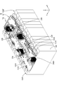
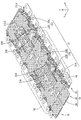
- FIG. 1 Perspective view of the electricity storage module of the embodiment
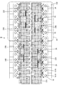
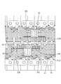
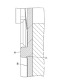
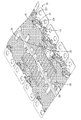
- the top view of the electrical storage module of embodiment A partially enlarged view of the frame R1 in FIG. Sectional view taken along the line AA of FIG. Sectional view taken along line BB of FIG.
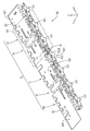
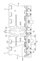
- the perspective view of the connection module of the embodiment Partial enlarged view of frame R2 in FIG.
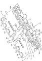
- the perspective view of the bus bar of the embodiment The perspective view of the resin protector of the embodiment Partial enlarged view of frame R3 in FIG.
- the top view which shows a mode that the expansion-contraction part was extended corresponding to the position gap of an electrode terminal.
- connection modules 1A and 1B of the present embodiment configure a power storage module M used as a drive source for vehicles such as electric vehicles and hybrid vehicles.
- the connection modules 1A and 1B are attached to a power storage element group 150G in which a plurality of power storage elements 150 are arranged in a line, and connect the plurality of power storage elements 150 in series.
- the power storage element 150 is, for example, a secondary battery. As shown in FIG. 1, each power storage element 150 has a flat rectangular parallelepiped shape, and has an electrode placement surface 150F (upper surface in FIG. 1) perpendicular to a surface facing the adjacent power storage element 150. ing.
- the electrode terminals 151A and 151B are arranged on the electrode arrangement surface 150F.
- One of the electrode terminals 151A and 151B is the positive electrode terminal 151A, and the other is the negative electrode terminal 151B.
- Each of the electrode terminals 151A and 151B has a columnar shape, and although not shown in detail, the outer peripheral surface is threaded.
- a plurality of power storage elements 150 are arranged in a line to form a power storage element group 150G.
- two adjacent power storage elements 150 have electrode terminals 151A and 151B of different polarities adjacent to each other (that is, the positive electrode terminal 151A of one power storage element 150 and another adjacent to this).
- the negative electrode terminal 151B of the power storage element 150 is arranged so as to be adjacent to each other.
- the arrangement direction of the plurality of power storage elements 150 (lower left-upper right direction in FIG. 1) is the X-axis direction, and the direction along the surface of the power storage element 150 facing the adjacent power storage element 150 (in FIG.
- the lower right-upper left direction will be described as the Y-axis direction, and the direction perpendicular to the electrode placement surface 150F (the vertical direction in FIG. 1) will be described as the Z-axis direction.
- connection modules 1A and 1B are modules that are assembled to the surface (upper surface in FIG. 1) formed by the electrode placement surface 150F of each power storage element 150 in the power storage element group 150G. As shown in FIG. 1, two connection modules 1A and 1B are assembled in one storage element group 150G, and one connection module 1A is one of two columns of electrode terminals 151A and 151B. The other connection module 1B is attached to the column (lower right column in FIG. 1) and the other column (upper left column in FIG. 1) of the electrode terminals 151A and 151B. Since the two connection modules 1A and 1B have the same configuration, the connection module 1A will be described below as an example.
- connection module 1A is connected to the flexible printed circuit board 20 (hereinafter referred to as “FPC20”) and the FPC20 to connect the positive electrode terminal 151A and the negative electrode terminal 151B of the adjacent power storage devices 150.
- FPC20 flexible printed circuit board 20
- a plurality of bus bars 10 (corresponding to a connecting member) and a resin protector 50 (corresponding to a holding member) that holds the bus bar 10 and the FPC 20 are provided.
- Bus bar 10 Each of the plurality of bus bars 10 is made of metal, and as shown in FIG. It is provided with an FPC connection piece 15 that is continuous and is connected to the FPC 20, and a locking wall 16 that is continuous from the FPC connection piece 15.
- the electrode connection portion 11 is a rectangular plate-shaped portion as a whole, and has two electrode insertion holes 12 through which the electrode terminals 151A and 151B can be inserted and two engagement recesses for engaging the resin protector 50. 13 and 13.
- One electrode insertion hole 12 is arranged at a position close to one short side 11S of the electrode connecting portion 11, and one is arranged at a position close to the other short side 11S.
- One of the two engaging recesses 13 is a recess recessed from one short side 11S of the electrode connecting part 11, and the other is a recess recessed from the other short side 11S.
- the electrode connecting portion 11 has a connection recess 14 that is recessed from one long side 11LA of the pair of long sides 11LA and 11LB.
- the connection recess 14 is a recess defined by a first inner edge 14A parallel to the long side 11LA and a pair of first side edges 14B connecting both ends of the first inner edge 14A and the long side 11LA. ..
- the FPC connection piece 15 is a rectangular plate piece-shaped portion extending from the first inner edge 14A in the same plane as the electrode connection portion 11.
- the locking wall 16 is a short plate wall-shaped portion that extends vertically from the tip of the FPC connection piece 15.
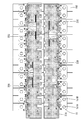
- the FPC 20 is a member for electrically connecting the plurality of bus bars 10 and the ECU (electronic control unit: not shown). Although not shown in detail, the FPC 20 has a plurality of conductive paths formed of copper foil. , And an insulating resin film that covers both surfaces of the conductive path. As shown in FIGS. 6 and 7, the FPC 20 includes a strip-shaped FPC main body 21 and a plurality of first movable portions 41 connected from the FPC main body 21 and connected to each of the plurality of bus bars 10. ..
- the FPC main body 21 has an elongated rectangular shape as a whole, and as shown in FIGS. 1 and 6, two slits (first slit 22A and second slit 22B) and two cutout portions (first cutout).
- the portion 23A and the second cutout portion 23B) are divided into three wiring portions (first wiring portion 31A, second wiring portion 31B, third wiring portion 31C).
- the first slit 22A and the second slit 22B are slits extending parallel to the pair of long sides 21LA and 21LB of the FPC main body 21, as shown in FIG.
- the first slit 22A is located near one end of the FPC main body 21 (lower left end in FIG. 6) and is close to one long side 21LA (lower side in FIG. 1) of the pair of long sides 21LA and 21LB of the FPC main body 21.
- the second slit 22B is arranged at a position near the other end (upper right end in FIG. 6) of the FPC main body 21 and close to the other long side 21LB (upper side in FIG. 1).
- the first cutout 23A is a relatively wide gap extending from the long side 21LA to the first slit 22A.
- the second cutout portion 23B is a relatively wide gap extending from the long side 21LA to the second slit 22B.
- the first wiring portion 31A is arranged at one end of the FPC main body 21 (lower left end in FIG. 6) and is divided by the first slit 22A and the first cutout portion 23A.
- the second wiring portion 31B is connected to the first wiring portion 31A and is connected to the second stretchable portion 32B (corresponding to the stretchable portion) partitioned by the first slit 22A and the second stretchable portion 32B. It is provided with a first cutout portion 23A, a second slit 22B, and a second busbar placement portion 33B (corresponding to a connection member placement portion) partitioned by the second cutout portion 23B.
- the third wiring portion 31C is connected to the second bus bar placement portion 33B, is connected to the third expansion / contraction portion 32C (corresponding to the expansion / contraction portion) divided by the second slit 22B, and is connected to the second slit 22B.
- the third bus bar arrangement portion 33C (corresponding to the connection member arrangement portion) partitioned by the second cutout portion 23B is provided.
- the first wiring portion 31A does not include an expansion / contraction portion, and the whole corresponds to a connection member arrangement portion to which the bus bar 10 is connected.
- the first wiring portion 31A, the second bus bar arrangement portion 33B, and the third bus bar arrangement portion 33C are arranged in a line along the long side 21LA.
- the third stretchable portion 32C is lightly bent along a plurality of folding lines 24 extending in a direction perpendicular to the long sides 21LA and 21LB, so that the third stretchable portion 32C has a mountain-shaped portion and a valley-shaped portion.
- the parts and the parts are bent alternately in a gentle corrugated shape, and by changing the folding angle, the parts can be expanded and contracted in the directions along the long sides 21LA and 21LB (the left and right directions in FIG. 3).
- the second bus bar arranging portion 33B and the third bus bar arranging portion 33C are allowed to be displaced with respect to the first wiring portion 31A in the direction in which they approach and separate.
- the second bus bar placement portion 33B is allowed to be displaced in a direction in which it approaches and separates from the first wiring portion 31A and the third bus bar placement portion 33C due to the extension and contraction of the second extension / contraction portion 32B.
- the third bus bar arrangement portion 33C is allowed to be displaced in a direction in which it approaches and separates from the second bus bar arrangement portion 33B by the expansion and contraction of the third expansion and contraction portion 32C.
- the first wiring portion 31A, the second bus bar arrangement portion 33B, and the third bus bar arrangement portion 33C each have a plurality of positioning holes 25.
- the first wiring portion 31A has an engagement hole 26 at a position close to the first cutout portion 23A.
- the second bus bar placement portion 33B has one engagement hole 26 at a position close to the first cutout portion 23A and one engagement hole 26 at a position close to the second cutout portion 23B.
- the third bus bar placement portion 33C has one engagement hole 26 at a position close to the second cutout portion 23B, and one engagement hole 26 at a position close to an edge opposite to the second bus bar placement portion 33B. There is.
- the first movable portion 41 is an S-shaped wire spring-shaped portion that is continuous from the FPC main body 21. As shown in FIG. 6, the plurality of first movable portions 41 are arranged in a line along the long side 21LA, and some of them are connected to the first wiring portion 31A and other portions are arranged. Some of them are connected to the second bus bar arranging portion 33B, and the rest of them are connected to the third bus bar arranging portion 33C. Although not shown in detail, the tip end portion of the first movable portion 41 is a joint portion in which a part of the conductive path is exposed as a joint land (not shown). Connected by soldering.
- the resin protector 50 is made of synthetic resin, and includes an FPC holding portion 51 that holds the FPC main body 21 and a plurality of busbar holding portions 121 and 131 that holds the busbar 10.
- the FPC holding unit 51 connects three holding units (first holding unit 61, second holding unit 71, third holding unit 81) and adjacent holding units 61, 71, 81. And a pair of first connecting portions 91 (corresponding to connecting portions) are formed, and as a whole, an elongated rectangular plate shape having a size substantially equal to that of the FPC main body 21 is formed.
- maintains 31 A of 1st wiring parts, and the part which adjoins 31 A of 1st wiring parts in the 2nd expansion-contraction part 32B.
- the second holding unit 71 includes a portion adjacent to the second bus bar placement portion 33B in the second stretchable portion 32B, a second bus bar placement portion 33B, and a portion adjacent to the second wiring portion 31B in the third stretchable portion 32C. Hold.
- the third holding unit 81 holds the portion of the third expansion / contraction portion 32C adjacent to the third bus bar arrangement portion 33C and the third bus bar arrangement portion 33C.
- the first holding unit 61 includes a first mounting plate 62 (corresponding to a mounting portion), first side ribs 63 rising from the first mounting plate 62, and the first mounting plate 62. It is provided with a first pressing piece 53A (corresponding to the sandwiching portion) and a plurality of second pressing pieces 53B (corresponding to the sandwiching portion) connected from the side ribs 63.
- the first mounting plate 62 is a rectangular plate-shaped portion as a whole, as shown in FIGS. 9 and 11.
- One surface of the first mounting plate 62 (the upper surface in FIG. 9) is a first mounting surface 62F on which the FPC main body 21 is mounted.
- the first side rib 63 is a streak-like portion that protrudes from one long side 62LA (upper side in FIG. 11) of the pair of long sides 62LA and 62LB of the first mounting plate 62.
- the first pressing piece 53 ⁇ / b> A is an elongated plate piece-shaped portion extending from the first side rib 63 in parallel with the first mounting plate 62, and between the first mounting plate 62 and the first mounting plate 62.
- the FPC main body 21 can be sandwiched and held.
- the second pressing piece 53B is a plate piece-shaped portion that extends from the first side rib 63 in parallel with the first mounting plate 62, and is shorter than the first pressing piece 53A.
- a plurality of second pressing pieces 53B are arranged closer to the second holding unit 71 than the first pressing pieces 53A.
- the first holding unit 61 includes a first center rib 52A protruding from the first mounting surface 62F, a positioning protrusion 54, and an FPC locking piece 55.
- the first center rib 52A is a stripe-shaped portion extending in parallel with the long sides 62LA and 62LB, and is arranged at a position corresponding to the first slit 22A.
- Each of the plurality of positioning protrusions 54 is a circular protrusion that protrudes from the first mounting surface 62F, and is arranged at a position corresponding to the positioning hole 25.
- the FPC locking piece 55 includes a locking piece main body that projects from the first mounting surface 62F and a locking projection that projects from the tip of the locking piece main body. It is arranged at a position corresponding to 26.
- the second holding unit 71 includes a second mounting plate 72 (corresponding to a mounting portion), second side ribs 73 rising from the second mounting plate 72, and the second side rib 73.
- a first pressing piece 53A and a plurality of second pressing pieces 53B connected from the side ribs 73 are provided.
- the second mounting plate 72 is a rectangular plate-shaped portion as a whole.
- One surface (the upper surface in FIG. 9) of the second mounting plate 72 is a second mounting surface 72F on which the FPC main body 21 is mounted.
- the second side rib 73 is a streak-like portion that protrudes from one long side 72LA (upper side in FIG. 11) of the pair of long sides 72LA and 72LB of the second mounting plate 72.
- the first pressing piece 53A extends from the central position of the second side rib 73.
- the plurality of second pressing pieces 53B are arranged on both sides of the first pressing piece 53A.
- the second holding unit 71 includes a second center rib 52B, a third center rib 52C, a plurality of positioning protrusions 54, and a plurality of FPC locking pieces that project from the second mounting surface 72F. 55.
- the second center rib 52B is a short streak-shaped portion extending parallel to the long sides 72LA and 72LB of the second mounting plate 72, and is arranged corresponding to the first slit 22A.
- the third center rib 52C is a short streak-shaped portion extending parallel to the long sides 72LA and 72LB of the second mounting plate 72, and is arranged corresponding to the second slit 22B.
- the plurality of positioning protrusions 54 and the plurality of FPC locking pieces 55 are arranged at positions corresponding to the positioning holes 25 and the engagement holes 26, respectively.
- the third holding unit 81 includes a third mounting plate 82 (corresponding to a mounting portion), a third side rib 83 rising from the third mounting plate 82, and the third mounting plate 82. It is provided with a plurality of second pressing pieces 53B connected from the side ribs 83.
- the third mounting plate 82 is a rectangular plate-shaped portion as a whole, as shown in FIGS. 9 and 11.
- One surface (upper surface in FIG. 9) of the third mounting plate 82 is a third mounting surface 82F on which the FPC main body 21 is mounted.
- the third side rib 83 is a streak-like portion protruding from one long side 82LA (upper side in FIG. 11) of the pair of long sides 82LA and 82LB of the third mounting plate 82.
- the plurality of second pressing pieces 53B extend from the third side ribs 83.
- the second holding unit 71 includes a fourth center rib 52D protruding from the second mounting surface 72F, a positioning protrusion 54, and a plurality of FPC locking pieces 55.
- the fourth center rib 52D is a short streak-shaped portion extending in parallel with the long sides 82LA and 82LB of the third mounting plate 82, and is arranged corresponding to the second slit 22B.
- the positioning protrusion 54 and the plurality of FPC locking pieces 55 are arranged at positions corresponding to the positioning hole 25 and the engaging hole 26, respectively, similarly to the first holding unit 61.
- one of the two sets of the first connecting portions 91 is a portion that connects the second mounting plate 72 and the third mounting plate 82, and has a pair of U-shapes.
- the two connection spring portions 92 are arranged to face each other, and in each connection spring portion 92, one end of the U-shape is the short side 72S of the second mounting plate 72 and the other end is the short side of the third mounting plate 82. It is connected to 82S.
- the other first connecting portion 91 is a portion that connects the first mounting plate 62 and the second mounting plate 72, and has the same configuration as the one first connecting portion 91. Have By these first connecting portions 91, the three holding units 61, 71, 81 can be displaced in the directions in which they approach and separate from each other.
- One of the third holding unit 81 and the one of the third holding unit 81 located at the end opposite to the second holding unit 71 is the fixed bus bar holding portion 131, and the other is the holding unit 61 via the second movable portion 111.
- 71, 81 is a movable busbar holding portion 121.
- the 2nd movable part 111 connected with the 2nd holding unit 71, the movable busbar holding part 121, and the fixed busbar holding part 131 are demonstrated, and the 2nd movable part 111 connected with the 1st holding unit 61 and the 3rd holding unit 81.
- the bus bar holding portions 121 and 131 the same configurations are denoted by the same reference numerals and description thereof will be omitted.
- the second mounting plate 72 has a plurality of spring recesses 101 recessed inward from the long sides 72LB.
- Each spring recess 101 is a recess defined by a second inner edge 101A parallel to the long side 72LB and a pair of second side edges 101B connecting both ends of the second inner edge 101A and the long side 72LB. ..
- the second movable portion 111 includes a plate-piece-shaped spring connecting piece 112 extending from the second inner edge 101A on the same plane as the first mounting plate 62, and a second piece from the spring connecting piece 112.
- a pair of spring plate portions 113 extending along the two inner edges 101A while bending in opposite directions are provided.
- Each of the pair of spring plate portions 113 has a leaf spring shape that extends from the spring connection piece 112 along the second inner edge 101A while curving in a U shape and then extends substantially perpendicularly to the spring connection piece 112. I am doing it.
- Each spring plate portion 113 can expand and contract in the direction along the long side 72LB of the second mounting plate 72 by the deformation of the U-shaped portion.
- the movable busbar holding portion 121 includes a back plate portion 122 that extends from the second movable portion 111, a bottom plate portion 123 that extends from the back plate portion 122, and an extension piece 125 that extends from the bottom plate portion 123.
- the first bus bar locking piece 126 and the two second bus bar locking pieces 127 are provided.
- the back plate portion 122 is a plate-shaped portion arranged in a posture perpendicular to the second mounting plate 72, and is connected to the respective tip portions of the pair of spring plate portions 113. Has been done.
- the bottom plate portion 123 is a plate-shaped portion that extends vertically from the back plate portion 122 in a direction opposite to the second mounting plate 72, and has two third slits 124.
- Each of the two third slits 124 extends from the extending end of the bottom plate portion 123 toward the back plate portion 122, and the bottom plate portion 123 is provided with the end plate portions 123A at both ends by these third slits 124.
- a central middle plate portion 123B is a plate-like portion extending from the extending end of the bottom plate portion 123 on the same plane as the bottom plate portion 123.
- the first bus bar locking piece 126 extends from the middle plate portion 123B and is arranged with a gap from the back plate portion 122, and the first bending piece 126A and the first bending piece 126A.
- a first locking claw 126B that projects from the extending end in the direction opposite to the back plate 122 is provided.
- the first bending piece 126A is slightly inclined so as to be farther from the back plate portion 122 as it is farther from the middle plate portion 123B.
- Each of the two second bus bar locking pieces 127 extends from each of the two end plate portions 123A, as shown in FIG. Although not shown in detail, each of the second bus bar locking pieces 127 faces the back plate portion 122 from the second bending piece that extends vertically from the extended end of the two end plate portions 123A and the tip of the second bending piece. And a second locking claw that protrudes.
- each movable busbar holding portion 121 with respect to the second mounting plate 72 is allowed to some extent by the second movable portion 111.
- the two spring plate portions 113 of the second movable portion 111 can expand and contract to move in the direction along the long side 72LB of the second mounting plate 72 (X-axis direction).
- the fixed bus bar holding part 131 does not have the second movable part 111, except that the back plate part 132 extends from the long side 72LB of the second mounting plate 72. It has the same configuration as that of the movable busbar holding portion 121.
- the same parts as those of the movable bus bar holding part 121 are designated by the same reference numerals and the description thereof will be omitted.
- the plurality of bus bar holding portions 121 and 131 are arranged in a line as shown in FIG. 9, and the adjacent movable bus bar holding portions 121 are connected by the U-shaped second connecting portion 140 as shown in FIG. It is connected.
- the fixed busbar holding portion 131 and the movable busbar holding portion 121 which are adjacent to each other are also connected by the second connecting portion 140.
- the movable busbar holding portions 121 adjacent to each other, and the fixed busbar holding portion 131 and the movable busbar holding portion 121 adjacent to each other are connected to each other in a state in which the variation in the mutual interval is allowed to some extent.
- connection module 1A An example of a procedure for assembling the connection module 1A having the above configuration will be described below.
- each bus bar 10 connects multiple bus bars 10 to the FPC 20.
- the FPC connecting piece 15 of each bus bar 10 is overlaid on each joining piece of the FPC 20 and joined by reflow soldering.
- the plurality of bus bars 10 are arranged in a line along the long side 21LA.
- Each bus bar 10 is in a state of being connected to the FPC main body 21 via the first movable portion 41, and the first movable portion 41 is deformed so that each bus bar 10 is attached to the long side 21LA of the FPC main body 21.
- the X-axis direction the direction in which the FPC main body 21 approaches and separates
- the Y-axis direction the direction in which the FPC main body 21 approaches and separates
- the Z-axis direction the thickness direction of the FPC main body 21
- the joined body of the FPC 20 and the plurality of bus bars 10 is assembled to the resin protector 50.
- the FPC main body 21 is placed on the mounting plates 62, 72, 82 so as to be inserted into the gaps between the mounting plates 62, 72, 82 and the pressing pieces 53A, 53B.
- Each of the plurality of positioning protrusions 54 is inserted into each of the plurality of positioning holes 25, the center ribs 52A and 52B are inserted into the first slit 22A, and the center ribs 52C and 52D are inserted into the second slit 22B.
- the first wiring part 31A is positioned on the first mounting plate 62
- the second busbar arranging part 33B is positioned on the second mounting plate 72
- the third busbar arranging part 33C is positioned on the third mounting plate 82.
- the third elastic portion 32C is provided between the second mounting plate 72 and the third mounting plate 82. It holds it while allowing some bending deformation.
- the height of the second pressing piece 53B from the second mounting surface 72F and the third mounting surface 82F is larger than the thickness of the FPC main body 21 (see also FIG. 4), and the second pressing piece 53B. Holds the third stretchable portion 32C while allowing some bending deformation.
- the second expansion / contraction portion 32B is arranged in the first mounting plate 62 and the second mounting plate 72. It is sandwiched and held while allowing bending deformation to some extent.
- each bus bar 10 is assembled to each bus bar holding portion 121, 131. While bending the first bus bar locking piece 126 and the second bus bar locking piece 127, the electrode connecting portion 11 is pushed toward the bottom plate portion 123. When the electrode connecting portion 11 comes into contact with the bottom plate portion 123, as shown in FIG. 7, the first bus bar locking piece 126 elastically returns, and the locking wall 16 becomes the middle plate portion 123B and the first locking claw 126B. Sandwiched between. Further, the second bus bar locking piece 127 is inserted into the engaging recess 13 and engages with the electrode connecting portion 11. In this way, each bus bar 10 is fixed to each bus bar holding portion 121, 131.
- the first movable portion 41 of the bus bar 10 is allowed to be displaced to some extent with respect to the FPC main body 21, so that the bus bar 10 can be easily assembled to the bus bar holding portions 121 and 131. It can be carried out. Further, by simply pushing the bus bar 10 toward the bottom plate portion 123, it can be easily assembled to the bus bar holding portions 121 and 131.
- the bus bar 10 is displaceably connected to the FPC main body 21 by the first movable portion 41, and the movable bus bar holding portion 121 is displaceably connected to the FPC holding portion 51 by the second movable portion 111. ing.
- the movable bus bar holding portion 121 and the bus bar 10 are assembled to each other, and with respect to the FPC holding portion 51 and the FPC main body 21, the long sides 62LB, 72LB, 82LB of the holding units 61, 71, 81 and Displacement in the direction along the long side 21LA of the FPC main body 21 (X-axis direction) is allowed.
- connection module 1A Assembly of Connection Module 1A to Storage Element Group 150G
- An example of a procedure for assembling the connection module 1A having the above configuration to the storage element group 150G will be described below.
- connection module 1A is arranged at a predetermined position on the storage element group 150G, and the electrode terminals 151A and 151B are inserted into the electrode insertion holes 12 of each bus bar 10. After that, nuts (not shown) are screwed onto the electrode terminals 151A and 151B to connect the electrode terminals 151A and 151B and the bus bar 10.
- the storage element group 150G configured by arranging a large number of storage elements 150, a large dimensional tolerance occurs due to manufacturing dimensional error of each storage element 150 and accumulation of assembly errors of the plurality of storage elements 150.
- the positional deviation of the electrode terminals 151A and 151B in the direction along the arrangement direction of the power storage elements 150 (X-axis direction) may increase.
- the FPC main body 21 of the FPC 20 includes a first wiring portion 31A, a second wiring portion 31B including a second bus bar placement portion 33B, and a third wiring portion 31C including a third bus bar placement portion 33C. It is divided into three parts. Then, the plurality of bus bars 10 are separately connected to the first wiring portion 31A, the second bus bar arrangement portion 33B, and the third bus bar arrangement portion 33C. According to such a configuration, each of the first wiring portion 31A, the second bus bar arranging portion 33B, and the third bus bar arranging portion 33C is connected to some of the power storage elements 150 in the power storage element group 150G. .. Therefore, it is possible to reduce the accumulation of the dimensional error, the assembly error, and the like of the power storage element 150 to which the first wiring portion 31A, the second bus bar arrangement portion 33B, and the third bus bar arrangement portion 33C correspond.
- the second bus bar placement portion 33B is allowed to be displaced toward and away from the first wiring portion 31A and the third bus bar placement portion 33C due to the extension and contraction of the second extension / contraction portion 32B.
- the third bus bar placement portion 33C is allowed to be displaced in a direction in which it approaches and separates from the second bus bar placement portion 33B by the extension and contraction of the third extension and contraction portion 32C.
- the second bus bar arranging portion 33B and the third bus bar arranging portion 33C are displaced in response to the positional deviation of the electrode terminals 151A and 151B caused by the dimensional tolerance of the storage element group 150G, and the bus bar 10 is moved to the electrode terminal 151A. , 151B can be assembled.
- the second expansion / contraction part 32B is bent to reduce the length, and the first wiring part 31A and the second bus bar are connected. The distance from the arrangement portion 33B can be reduced.
- the third expansion / contraction part 32C can be bent to reduce its length, and the distance between the second bus bar arrangement part 33B and the third bus bar arrangement part 33C can be reduced.
- the second expansion / contraction portion 32B is extended to connect the first wiring portion 31A and the second bus bar arrangement portion 33B. The distance can be increased.
- the third expansion / contraction portion 32C can be extended to increase the distance between the second bus bar arrangement portion 33B and the third bus bar arrangement portion 33C. In this way, the positional deviation of the electrode terminals 151A and 151B can be absorbed.
- each bus bar 10 is displaced according to the positional deviation of the electrode terminals 151A and 151B due to the dimensional tolerance of the storage element group 150G, and the electrode terminals are displaced. It can be assembled to 151A and 151B.
- each movable busbar holding portion 121 is fixed to the fixed busbar holding portion 131.
- the bus bar 10 held by the fixed bus bar holding portion 131 as a reference the other bus bar 10 is displaced so that the distance between the adjacent bus bars 10 becomes small, and the displacement of the electrode terminals 151A and 151B can be dealt with.
- the second movable portion 111 and the second connecting portion 140 are deformed so that each movable busbar holding portion 121 is fixed to the fixed busbar holding portion 131.
- the bus bar 10 held by the fixed bus bar holding portion 131 as a reference the other bus bar 10 is displaced so that the distance between the adjacent bus bars 10 becomes large, and the displacement of the electrode terminals 151A and 151B can be dealt with.
- connection module 1A to the electricity storage element group 150G due to the dimensional tolerance of the electricity storage element group 150G, and improve the assembling workability.
- the shape of the flexible FPC 20 is held constant, and together with the plurality of bus bars 10, they are collectively placed at a predetermined position on the storage element group 150G. Can be set.
- the resin protector 50 includes three holding units 61, 71, 81.
- the first wiring portion 31A is on the first placing plate 62
- the second bus bar arranging portion 33B is on the second placing plate 72.
- the third bus bar placement portion 33C is held by the third placement plate 82 in a positioned state. Since the three holding units 61, 71, 81 are displaceable in the direction toward and away from each other by the first connecting portion 91, the first wiring portion 31A, the second bus bar arranging portion 33B, and the third holding portion 61.
- the distance between the three holding units 61, 71, 81 can be changed in response to the change in the distance of the bus bar placement portion 33C. This allows the resin protector 50 to hold the FPC 20 without inhibiting the absorption of the dimensional tolerance due to the variation in the distance between the first wiring portion 31A, the second bus bar arrangement portion 33B, and the third bus bar arrangement portion 33C.
- the connection module 1A is a module that is attached to the power storage element group 150G configured by the plurality of power storage elements 150 including the electrode terminals 151A and 151B to connect the plurality of power storage elements 150. Therefore, the FPC 20 and the plurality of bus bars 10 connected to the FPC 20 and connecting the electrode terminals 151A and 151B of the adjacent power storage elements 150 to each other are provided.
- the FPC 20 includes a first wiring part 31A, a second busbar arranging part 33B, and a third busbar arranging part 33C to which the busbar 10 is connected.
- the FPC 20 is connected to the second bus bar arranging portion 33B, and the second expanding / contracting portion 32B is allowed to expand / contract in the direction of approaching / separating from the first wiring portion 31A and the third bus bar arranging portion 33C, and the third bus bar
- the third expansion / contraction portion 32C is provided which is continuous from the arrangement portion 33C and is allowed to expand / contract in the direction of approaching / separating from the second bus bar arrangement portion 33B.
- each of the first wiring portion 31A, the second bus bar arranging portion 33B, and the third bus bar arranging portion 33C is connected to some of the power storage elements 150 in the power storage element group 150G.
- the first wiring portion 31A, the second bus bar arranging portion 33B, and the third bus bar arranging portion 33C respectively correspond to accumulation of manufacturing dimensional error of each power storage element 150, assembly error of a plurality of power storage elements 150, and the like. Can be made smaller.
- the distance between the first wiring portion 31A, the second bus bar arrangement portion 33B and the third bus bar arrangement portion 33C is changed by the expansion and contraction of the second elastic portion 32B and the third elastic portion 32C, and the positions of the electrode terminals 151A and 151B are changed. It is possible to cope with the deviation. As a result, it is possible to avoid difficulty in assembling the connection module 1A to the electricity storage element group 150G due to the dimensional tolerance of the electricity storage element group 150G, and improve the assembling workability.
- the second stretchable portion 32B and the third stretchable portion 32C are bent along a plurality of folding lines 24 arranged side by side, so that a wavy shape in which mountain-shaped portions and valley-shaped portions are alternately arranged. It has a shape. With such a configuration, the second elastic portion 32B and the third elastic portion 32C can have a simple structure, and the complication of the structure of the connection module 1A can be avoided.
- connection module 1A includes a resin protector 50 that holds the plurality of bus bars 10 and the FPC 20.
- the resin protector 50 includes a plurality of holding units 61, 71, 81 that respectively hold the first wiring portion 31A, the second bus bar arrangement portion 33B, and the third bus bar arrangement portion 33C, and adjacent holding units 61, 71. , 81, and a first connecting portion 91 for connecting so as to be displaceable in a direction in which they approach and separate from each other.
- the shape of the flexible FPC 20 can be held constant and can be collectively set at a predetermined position on the storage element group 150G together with the plurality of bus bars 10.
- the first connecting portion 91 allows the first wiring portion 31A, the second bus bar arrangement portion 33B, and the third bus bar arrangement portion 33C to follow the change in the distance between the adjacent holding units 61, 71, 81. The distance can be varied. This allows the resin protector 50 to hold the FPC 20 without inhibiting the displacement of the first wiring portion 31A, the second bus bar arrangement portion 33B, and the third bus bar arrangement portion 33C.
- the second holding unit 71 holds the second placing plate 72 on which the FPC 20 is placed and the second placing plate 72 by sandwiching the second stretchable portion 32B or the third stretchable portion 32C.
- the first holding piece 53A and the second holding piece 53B are provided, and the distance between the first holding piece 53A and the second holding piece 53B and the second mounting plate 72 is larger than the thickness of the FPC 20.
- the FPC 20 includes the first wiring portion 31A, the second bus bar placement portion 33B, and the third bus bar placement portion 33C, but the connection member placement portion included in the flexible printed circuit board is It may be two or four or more.
- the numbers of the expansion / contraction part and the holding unit may be designed so as to correspond to the number of connection member arrangement parts.
- the first connecting portion 91 is configured by the pair of U-shaped connecting spring portions 92 that are arranged to face each other, but the shape of the first connecting portion 91 is adjacent to each other. Any shape may be used as long as the units can be connected so as to be displaceable in the directions of approaching and separating from each other.
- one U-shaped spring portion may be used, or an S-shaped spring portion may be used. Absent.
- Connection module 10 ... Bus bar (connection member) 20 ... FPC (flexible printed circuit board) 24 ... Folding line 31A ... 1st wiring part (connection member arrangement part) 32B ... 2nd expansion-contraction part (expansion-contraction part) 32C ... Third stretchable portion (stretchable portion) 33B ... Second bus bar arrangement portion (connection member arrangement portion) 33C ... 3rd bus bar arrangement part (connection member arrangement part) 50 ... Resin protector (holding member) 53A ... 1st pressing piece (sandwiching part) 53B ... Second pressing piece (sandwiching part) 61 ... First holding unit (holding unit) 62 ... 1st mounting plate (mounting part) 71 ...
- Second holding unit (holding unit) 72 ... Second mounting plate (mounting portion) 81 ... Third holding unit (holding unit) 82 ... Third mounting plate (mounting portion) 91 ... 1st connection part (connection part) 150 ... Electric storage element 150G ... Electric storage element group 151A, 151B ... Electrode terminal
Landscapes
- Chemical & Material Sciences (AREA)
- Chemical Kinetics & Catalysis (AREA)
- Electrochemistry (AREA)
- General Chemical & Material Sciences (AREA)
- Engineering & Computer Science (AREA)
- Microelectronics & Electronic Packaging (AREA)
- Manufacturing & Machinery (AREA)
- Connection Of Batteries Or Terminals (AREA)
- Battery Mounting, Suspending (AREA)
- Coupling Device And Connection With Printed Circuit (AREA)
Priority Applications (2)
| Application Number | Priority Date | Filing Date | Title |
|---|---|---|---|
| CN201980074054.3A CN113016105A (zh) | 2018-11-22 | 2019-11-01 | 连接模块 |
| US17/296,067 US12113243B2 (en) | 2018-11-22 | 2019-11-01 | Connection module |
Applications Claiming Priority (2)
| Application Number | Priority Date | Filing Date | Title |
|---|---|---|---|
| JP2018-219299 | 2018-11-22 | ||
| JP2018219299A JP6986504B2 (ja) | 2018-11-22 | 2018-11-22 | 接続モジュール |
Publications (1)
| Publication Number | Publication Date |
|---|---|
| WO2020105401A1 true WO2020105401A1 (ja) | 2020-05-28 |
Family
ID=70773638
Family Applications (1)
| Application Number | Title | Priority Date | Filing Date |
|---|---|---|---|
| PCT/JP2019/043018 Ceased WO2020105401A1 (ja) | 2018-11-22 | 2019-11-01 | 接続モジュール |
Country Status (4)
| Country | Link |
|---|---|
| US (1) | US12113243B2 (enExample) |
| JP (1) | JP6986504B2 (enExample) |
| CN (1) | CN113016105A (enExample) |
| WO (1) | WO2020105401A1 (enExample) |
Families Citing this family (7)
| Publication number | Priority date | Publication date | Assignee | Title |
|---|---|---|---|---|
| JP2020205176A (ja) * | 2019-06-17 | 2020-12-24 | 矢崎総業株式会社 | 回路体、基板と回路体との接続構造、及び、バスバモジュール |
| KR102785549B1 (ko) * | 2019-08-02 | 2025-03-26 | 주식회사 엘지에너지솔루션 | 이동 가능한 버스바 조립체를 구비한 배터리 팩 및 이를 포함하는 이차전지 |
| KR102748824B1 (ko) * | 2020-01-08 | 2024-12-31 | 주식회사 엘지에너지솔루션 | 배터리 팩, 전자 디바이스, 및 자동차 |
| JP7240372B2 (ja) | 2020-12-21 | 2023-03-15 | プライムプラネットエナジー&ソリューションズ株式会社 | 蓄電モジュールおよびその製造方法 |
| JP7560509B2 (ja) * | 2022-05-16 | 2024-10-02 | 矢崎総業株式会社 | バスバモジュール |
| JP2024055095A (ja) * | 2022-10-06 | 2024-04-18 | 株式会社オートネットワーク技術研究所 | 配線モジュール |
| US20240332758A1 (en) * | 2023-03-27 | 2024-10-03 | Samsung Sdi Co., Ltd. | Battery pack and method of manufacturing the battery pack |
Citations (3)
| Publication number | Priority date | Publication date | Assignee | Title |
|---|---|---|---|---|
| JPS5421449B2 (enExample) * | 1971-07-16 | 1979-07-31 | ||
| JP2012227002A (ja) * | 2011-04-20 | 2012-11-15 | Auto Network Gijutsu Kenkyusho:Kk | 配線モジュール |
| JP2013143281A (ja) * | 2012-01-11 | 2013-07-22 | Auto Network Gijutsu Kenkyusho:Kk | 電池用配線モジュール |
Family Cites Families (8)
| Publication number | Priority date | Publication date | Assignee | Title |
|---|---|---|---|---|
| JP5702947B2 (ja) * | 2010-04-22 | 2015-04-15 | 矢崎総業株式会社 | 配線材 |
| JP5720530B2 (ja) * | 2011-10-28 | 2015-05-20 | 株式会社オートネットワーク技術研究所 | 電池用配線モジュール |
| JP2013105571A (ja) * | 2011-11-11 | 2013-05-30 | Auto Network Gijutsu Kenkyusho:Kk | 電池配線モジュール |
| JP6257889B2 (ja) | 2012-10-23 | 2018-01-10 | 日本メクトロン株式会社 | バスバー付きフレキシブルプリント配線板およびその製造方法、並びにバッテリシステム |
| EP2950386A1 (en) | 2012-12-18 | 2015-12-02 | Panasonic Corporation | Communication antenna unit and mobile terminal apparatus |
| JP5421449B1 (ja) * | 2012-12-18 | 2014-02-19 | パナソニック株式会社 | 携帯端末装置 |
| JP6136697B2 (ja) | 2013-07-22 | 2017-05-31 | 株式会社デンソー | 組電池 |
| JP2015185226A (ja) * | 2014-03-20 | 2015-10-22 | 愛三工業株式会社 | バスバーモジュール |
-
2018
- 2018-11-22 JP JP2018219299A patent/JP6986504B2/ja active Active
-
2019
- 2019-11-01 WO PCT/JP2019/043018 patent/WO2020105401A1/ja not_active Ceased
- 2019-11-01 CN CN201980074054.3A patent/CN113016105A/zh active Pending
- 2019-11-01 US US17/296,067 patent/US12113243B2/en active Active
Patent Citations (3)
| Publication number | Priority date | Publication date | Assignee | Title |
|---|---|---|---|---|
| JPS5421449B2 (enExample) * | 1971-07-16 | 1979-07-31 | ||
| JP2012227002A (ja) * | 2011-04-20 | 2012-11-15 | Auto Network Gijutsu Kenkyusho:Kk | 配線モジュール |
| JP2013143281A (ja) * | 2012-01-11 | 2013-07-22 | Auto Network Gijutsu Kenkyusho:Kk | 電池用配線モジュール |
Also Published As
| Publication number | Publication date |
|---|---|
| JP2020087666A (ja) | 2020-06-04 |
| CN113016105A (zh) | 2021-06-22 |
| US12113243B2 (en) | 2024-10-08 |
| JP6986504B2 (ja) | 2021-12-22 |
| US20220021083A1 (en) | 2022-01-20 |
Similar Documents
| Publication | Publication Date | Title |
|---|---|---|
| JP7212504B2 (ja) | 接続モジュール | |
| WO2020105401A1 (ja) | 接続モジュール | |
| JP6793690B2 (ja) | コネクタ付き回路体、及び、バスバモジュール | |
| JP6642696B2 (ja) | 電源装置 | |
| JP2020205175A (ja) | バスバモジュール | |
| JP6145314B2 (ja) | バスバモジュール及び電源装置 | |
| WO2020105399A1 (ja) | 接続モジュール | |
| JP2020009604A (ja) | 組電池 | |
| CN112106221B (zh) | 连接模块及蓄电模块 | |
| JP2013105698A (ja) | 電源装置 | |
| JP2020087666A5 (enExample) | ||
| JP6837042B2 (ja) | 電池導電接続シート及び電池導電接続モジュール | |
| WO2020105244A1 (ja) | 支持部材及びバッテリモジュール | |
| JP6985240B2 (ja) | 接続モジュール | |
| JP7308328B2 (ja) | 接続モジュール | |
| CN113131058B (zh) | 电池组 | |
| JP2014157731A (ja) | 電源装置 | |
| JP2025035338A (ja) | バスバー及び配線モジュール | |
| KR20220049625A (ko) | 용량 가변 적응형 배터리 모듈의 결합 구조 | |
| JP2024115604A (ja) | バッテリ装置 | |
| CN120414003A (zh) | 汇流条 | |
| JP2022147174A (ja) | 絶縁リング、組電池及び組電池の製造方法 |
Legal Events
| Date | Code | Title | Description |
|---|---|---|---|
| 121 | Ep: the epo has been informed by wipo that ep was designated in this application |
Ref document number: 19887290 Country of ref document: EP Kind code of ref document: A1 |
|
| NENP | Non-entry into the national phase |
Ref country code: DE |
|
| 122 | Ep: pct application non-entry in european phase |
Ref document number: 19887290 Country of ref document: EP Kind code of ref document: A1 |