WO2020105244A1 - 支持部材及びバッテリモジュール - Google Patents
支持部材及びバッテリモジュールInfo
- Publication number
- WO2020105244A1 WO2020105244A1 PCT/JP2019/034514 JP2019034514W WO2020105244A1 WO 2020105244 A1 WO2020105244 A1 WO 2020105244A1 JP 2019034514 W JP2019034514 W JP 2019034514W WO 2020105244 A1 WO2020105244 A1 WO 2020105244A1
- Authority
- WO
- WIPO (PCT)
- Prior art keywords
- support
- support case
- case
- main body
- cases
- Prior art date
Links
Images


Classifications
-
- H—ELECTRICITY
- H01—ELECTRIC ELEMENTS
- H01M—PROCESSES OR MEANS, e.g. BATTERIES, FOR THE DIRECT CONVERSION OF CHEMICAL ENERGY INTO ELECTRICAL ENERGY
- H01M50/00—Constructional details or processes of manufacture of the non-active parts of electrochemical cells other than fuel cells, e.g. hybrid cells
- H01M50/50—Current conducting connections for cells or batteries
- H01M50/502—Interconnectors for connecting terminals of adjacent batteries; Interconnectors for connecting cells outside a battery casing
- H01M50/507—Interconnectors for connecting terminals of adjacent batteries; Interconnectors for connecting cells outside a battery casing comprising an arrangement of two or more busbars within a container structure, e.g. busbar modules
-
- H—ELECTRICITY
- H01—ELECTRIC ELEMENTS
- H01M—PROCESSES OR MEANS, e.g. BATTERIES, FOR THE DIRECT CONVERSION OF CHEMICAL ENERGY INTO ELECTRICAL ENERGY
- H01M50/00—Constructional details or processes of manufacture of the non-active parts of electrochemical cells other than fuel cells, e.g. hybrid cells
- H01M50/20—Mountings; Secondary casings or frames; Racks, modules or packs; Suspension devices; Shock absorbers; Transport or carrying devices; Holders
- H01M50/233—Mountings; Secondary casings or frames; Racks, modules or packs; Suspension devices; Shock absorbers; Transport or carrying devices; Holders characterised by physical properties of casings or racks, e.g. dimensions
- H01M50/242—Mountings; Secondary casings or frames; Racks, modules or packs; Suspension devices; Shock absorbers; Transport or carrying devices; Holders characterised by physical properties of casings or racks, e.g. dimensions adapted for protecting batteries against vibrations, collision impact or swelling
-
- H—ELECTRICITY
- H01—ELECTRIC ELEMENTS
- H01M—PROCESSES OR MEANS, e.g. BATTERIES, FOR THE DIRECT CONVERSION OF CHEMICAL ENERGY INTO ELECTRICAL ENERGY
- H01M10/00—Secondary cells; Manufacture thereof
- H01M10/42—Methods or arrangements for servicing or maintenance of secondary cells or secondary half-cells
- H01M10/48—Accumulators combined with arrangements for measuring, testing or indicating the condition of cells, e.g. the level or density of the electrolyte
- H01M10/486—Accumulators combined with arrangements for measuring, testing or indicating the condition of cells, e.g. the level or density of the electrolyte for measuring temperature
-
- H—ELECTRICITY
- H01—ELECTRIC ELEMENTS
- H01M—PROCESSES OR MEANS, e.g. BATTERIES, FOR THE DIRECT CONVERSION OF CHEMICAL ENERGY INTO ELECTRICAL ENERGY
- H01M50/00—Constructional details or processes of manufacture of the non-active parts of electrochemical cells other than fuel cells, e.g. hybrid cells
- H01M50/20—Mountings; Secondary casings or frames; Racks, modules or packs; Suspension devices; Shock absorbers; Transport or carrying devices; Holders
- H01M50/204—Racks, modules or packs for multiple batteries or multiple cells
- H01M50/207—Racks, modules or packs for multiple batteries or multiple cells characterised by their shape
- H01M50/209—Racks, modules or packs for multiple batteries or multiple cells characterised by their shape adapted for prismatic or rectangular cells
-
- H—ELECTRICITY
- H01—ELECTRIC ELEMENTS
- H01M—PROCESSES OR MEANS, e.g. BATTERIES, FOR THE DIRECT CONVERSION OF CHEMICAL ENERGY INTO ELECTRICAL ENERGY
- H01M50/00—Constructional details or processes of manufacture of the non-active parts of electrochemical cells other than fuel cells, e.g. hybrid cells
- H01M50/20—Mountings; Secondary casings or frames; Racks, modules or packs; Suspension devices; Shock absorbers; Transport or carrying devices; Holders
- H01M50/284—Mountings; Secondary casings or frames; Racks, modules or packs; Suspension devices; Shock absorbers; Transport or carrying devices; Holders with incorporated circuit boards, e.g. printed circuit boards [PCB]
- H01M50/287—Fixing of circuit boards to lids or covers
-
- H—ELECTRICITY
- H01—ELECTRIC ELEMENTS
- H01M—PROCESSES OR MEANS, e.g. BATTERIES, FOR THE DIRECT CONVERSION OF CHEMICAL ENERGY INTO ELECTRICAL ENERGY
- H01M50/00—Constructional details or processes of manufacture of the non-active parts of electrochemical cells other than fuel cells, e.g. hybrid cells
- H01M50/50—Current conducting connections for cells or batteries
- H01M50/502—Interconnectors for connecting terminals of adjacent batteries; Interconnectors for connecting cells outside a battery casing
- H01M50/519—Interconnectors for connecting terminals of adjacent batteries; Interconnectors for connecting cells outside a battery casing comprising printed circuit boards [PCB]
-
- Y—GENERAL TAGGING OF NEW TECHNOLOGICAL DEVELOPMENTS; GENERAL TAGGING OF CROSS-SECTIONAL TECHNOLOGIES SPANNING OVER SEVERAL SECTIONS OF THE IPC; TECHNICAL SUBJECTS COVERED BY FORMER USPC CROSS-REFERENCE ART COLLECTIONS [XRACs] AND DIGESTS
- Y02—TECHNOLOGIES OR APPLICATIONS FOR MITIGATION OR ADAPTATION AGAINST CLIMATE CHANGE
- Y02E—REDUCTION OF GREENHOUSE GAS [GHG] EMISSIONS, RELATED TO ENERGY GENERATION, TRANSMISSION OR DISTRIBUTION
- Y02E60/00—Enabling technologies; Technologies with a potential or indirect contribution to GHG emissions mitigation
- Y02E60/10—Energy storage using batteries
Definitions
- the present invention relates to a support member and a battery module.
- a voltage monitoring device is provided to monitor the voltage of the battery.
- This voltage monitoring device includes a voltage monitoring unit attached to a battery. And this voltage monitoring unit is provided with the flexible printed wiring board which has several wiring electrically connected to each electrode in a battery.
- the battery is composed of a plurality of cells, and the plurality of cells are electrically connected by a metal member called a bus bar.
- the flexible printed wiring board and the bus bar are supported by the cover. The cover is attached to the battery.
- An object of the present invention is to provide a support member and a battery module in consideration of variations in battery dimensions, and to alleviate stress concentration of the support member.
- the present invention adopts the following means in order to solve the above problems.
- the support member of the present invention is A support member for attaching to a battery configured by arranging a plurality of cells, A plurality of support cases each having a mounting portion on which a conductive member electrically connecting the plurality of cells can be mounted, a main body portion to which the mounting portion is connected, and a slide portion connected to the main body portion.
- the plurality of support cases are connected, The slide portion of one adjacent support case of the plurality of support cases is slidably accommodated in the main body portion of the other adjacent support case of the plurality of support cases, By pulling out a part of the slide portion of the one support case from the main body portion of the other support case, a gap between the one support case and the other support case is widened, By accommodating at least a part of the slide portion of the one support case in the main body portion of the other support case, a gap between the one support case and the other support case is narrowed. ..
- the battery module of the present invention A battery configured by arranging a plurality of cells, A plurality of supports provided with a mounting portion on which a conductive member electrically connecting the plurality of cells is mounted, a main body portion to which the mounting portion is connected, and a slide portion connected to the main body portion.
- a plurality of support cases are connected, and the slide portion of one of the support cases adjacent to each other is the main body portion of the other support case of the other adjacent support case of the plurality of support cases. It is slidably housed in.
- the length of the supporting member becomes longer, and by decreasing the distance between the one supporting case and the other supporting case, the length of the supporting member becomes shorter.
- a part of the slide part of one support case 121 is pulled out from the main body part of the other support case, or at least a part of the slide part of one support case is housed in the main body part of the other support case.
- the length of the support member can be adjusted. Therefore, when the support member is attached to the battery, the length of the support member can be adjusted according to the variation in the size of the battery. Therefore, the support member 120 can be attached to the battery in consideration of the variation in the dimensions of the battery.
- the support member expands and contracts, whereby the stress concentration of the support member can be relieved.
- the main body section and the slide section of the plurality of support cases are connected via a hinge, and the slide section with respect to the main body section of the one support case.
- the angle of the other support case with respect to the one support case may be changed by changing the angle of.
- the support member can be attached to the battery while bending or bending the support member, and the support member can be easily attached to the battery.
- the conductive member may be mounted on the mounting portion so as to be movable in the alignment direction of the plurality of support cases.
- the conductive member can be moved in the direction in which the plurality of support cases are arranged while the support member is attached to the battery. Therefore, the conductive member can be arranged in the plurality of cells according to the manufacturing tolerance of the thickness of each cell. Can be moved in any direction.
- a plurality of conductive members may be mounted on each of the plurality of support cases.
- the support member can be expanded and contracted using the support case in which a plurality of conductive members are mounted.
- the battery module of the present invention may include a flexible printed wiring board having a flat portion and a bending portion and supported by the supporting member, and the bending portion may be located directly above the hinge.
- the stress concentration of the support member can be alleviated in the support member and the battery module in consideration of the dimensional variation of the battery.
- FIG. 1 is a plan view of a voltage device and a battery module according to an embodiment.
- FIG. 2 is a perspective view of the battery module according to the embodiment.
- FIG. 3 is a side view of the battery module according to the embodiment.
- FIG. 4 is a perspective view of the support member according to the embodiment.
- FIG. 5 is a plan view of the support case according to the embodiment.
- FIG. 6 is a plan view of the support case according to the embodiment.
- FIG. 7 is a perspective view of the support member according to the embodiment.
- FIG. 8 is a plan view of the support member according to the embodiment.
- FIG. 9 is a plan view of the support member according to the embodiment.
- FIG. 10 is a perspective view of the support member according to the embodiment.
- FIG. 11 is a cross-sectional view of the battery module according to the embodiment.
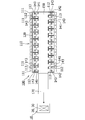
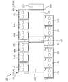
- FIG. 1 is a plan view of a monitoring device 10 and a battery module 100 according to the embodiment.
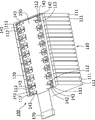
- FIG. 2 is a perspective view showing the configuration of the battery module 100 according to the embodiment.
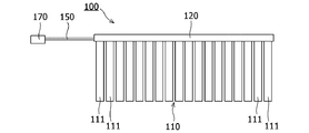
- FIG. 3 is a side view of the monitoring device 10 and the battery module 100 according to the embodiment.
- the monitoring device 10 includes a voltage monitoring device body 20 and a temperature measuring device body 30. In the example shown in FIG. 1, the voltage monitoring device body 20 and the temperature measuring device body 30 are integrated.
- the battery module 100 includes a battery 110, a support member 120, a plurality of bus bars 141 and 142, and a flexible printed wiring board (hereinafter referred to as FPC) 150. Further, the battery module 100 includes a connector 170 connected to the monitoring device 10. The monitoring device 10 monitors the voltage of the battery 110 and measures the temperature of the battery 110.
- the support member 120 supports the bus bars 141 and 142 and the FPC 150. When attaching the support member 120 to the battery 110, the support member 120 is arranged on the battery 110.
- the support member 120 has an attachment member for attaching the support member 120 to the battery 110.
- the battery 110 is configured by arranging (stacking) a plurality of cells 111. In the configuration example of the battery module 100 shown in FIGS. 1 to 3, a plurality of cells 111 are arranged side by side in a direction orthogonal to the longitudinal direction of the cells 111 (hereinafter referred to as the arrangement direction of the cells 111).
- Each of the plurality of cells 111 includes a positive electrode terminal 112 and a negative electrode terminal 113.
- the positive electrode terminal 112 and the negative electrode terminal 113 have a bolt shape and protrude from the upper surface of the cell 111.
- the positive electrode terminal 112 of one cell 111 and the negative electrode terminal 113 of the other cell 111 are aligned in the arrangement direction of the cells 111. Therefore, in the battery 110, the plurality of positive electrode terminals 112 and the plurality of negative electrode terminals 113 are alternately arranged in the arrangement direction of the cells 111.
- the positive electrode terminal 112 and the negative electrode terminal 113 of the adjacent cells 111 are electrically connected by the bus bar 141.
- the plurality of cells 111 are configured to be connected in series by electrically connecting the adjacent positive electrode terminal 112 and negative electrode terminal 113 by the bus bar 141.
- the bus bars 141 and 142 are conductive members. A plate-shaped metal is exemplified as the conductive member.
- the number of cells 111 is not limited to the configuration example of the battery module 100 shown in FIGS. 1 to 3, and may be determined according to the output voltage of the battery 110, for example.
- the bus bars 141 and 142 have elongated holes 143. When the bus bars 141 and 142 are attached to the battery 110, the positive electrode terminal 112 and the negative electrode terminal 113 are inserted into the long holes 143 of the bus bars 141 and 142.
- the bus bars 141 and 142 are not limited to the long holes 143, and may have round holes. The positive electrode terminal 112 and the negative electrode terminal 113 may be inserted into the round holes of the bus bars 141 and 142.
- the FPC 150 includes a flexible film and a plurality of wirings.
- the plurality of wirings are made of, for example, copper foil. Some of the plurality of wirings may be used as voltage monitoring wirings, and other portions of the plurality of wirings may be used as temperature measurement wirings. In this case, the voltage monitoring wiring and the temperature measuring wiring are connected to the connector 170.
- FIG. 4 is a perspective view of the support member 120 according to the embodiment.
- the support member 120 is composed of a plurality of support cases (housings) 121. By connecting the plurality of support cases 121 to each other, the plurality of support cases 121 can be connected.
- FIG. 4A shows a state before connecting the plurality of support cases 121
- FIG. 4B shows a state after connecting the plurality of support cases 121. As shown in FIG.
- the plurality of support cases 121A have the same shape
- the shape of the support case 121B is different from the shapes of the support cases 121A and 121C
- the shape of the support case 121C is the same as the shapes of the support cases 121A and 121B. different.
- FIGS. 5 and 6 are plan views of the support case 121A according to the embodiment.
- a plurality of bus bars 141 are mounted on the support case 121A.
- the plurality of bus bars 141 are supported by the support case 121A.
- 121 A of support cases have the main-body part 122 and the some mounting part 123 connected to the main-body part 122.
- One bus bar 141 can be mounted on each of the plurality of mounting portions 123.
- FIG. 5 shows a state before mounting the plurality of bus bars 141 on the support case 121A
- FIG. 6 shows a state after mounting the plurality of bus bars 141 on the support case 121A.
- the support case 121A may include a main body 122 and one mounting portion 123 connected to the main body 122.
- a plurality of bus bars 141 may be mounted on one mounting portion 123.
- the support cases 121B and 121B have a main body 122 and a plurality of mounting portions 123 connected to the main body 122, as in the support case 121A.
- a plurality of bus bars 141 are mounted on the support cases 121B and 121C, similarly to the support case 121A.
- One bus bar 142 is mounted on each of the support cases 121B and 121C.
- the support cases 121B and 121C may include a main body 122 and one mounting portion 123 connected to the main body 122. In this case, a plurality of bus bars 141 and one bus bar 142 may be mounted on one mounting portion 123.
- bus bars 141 are mounted on one support case 121A, but the number of bus bars 141 mounted on the support case 121A is not limited. At least two bus bars 141 are mounted on the support case 121A. In the configuration example shown in FIG. 6, three bus bars 141A are continuously mounted in the support case 121A, and three bus bars 141B are continuously mounted in the support case 121A.
- the main body 122 is arranged so as to be sandwiched between the three bus bars 141A and the three bus bars 141B when viewed from the normal direction of the upper surface 122A of the main body 122.
- a part of the plurality of bus bars 141 mounted in the support case 121A and the other part thereof are arranged with the main body 122 separated.
- a pressing portion 124 and a pressing portion 125 are provided inside the mounting portion 123.
- the pressing portion 124 contacts the upper surface of the bus bar 141
- the pressing portion 125 contacts the side surface and the lower surface of the bus bar 141.
- the pressing portion 125 has flexibility. The pressing portion 125 presses the bus bar 141 toward the main body portion 122 and the pressing portion 124 so that the bus bar 141 can move. In this way, the bus bar 141 is mounted on the mounting portion 123 in a state where the bus bar 141 can be moved in the parallel direction.
- the bus bar 142 is mounted on the mounting portion 123 in a state where the bus bar 142 can be moved in the parallel direction.
- the bus bars 141 and 142 are mounted on the support case 121 so as to be movable in the direction in which the plurality of support cases 121 are arranged.
- the bus bars 141 and 142 can be moved in the arrangement direction of the cells 111 with the support member 120 attached to the battery 110.
- the support case 121 has a hinge 126 and a slide portion 127.
- the slide portion 127 is connected to the main body portion 122 via a hinge 126.
- the plurality of support cases 121 are connected to each other, and the slide portion 127 of the adjacent one of the plurality of support cases 121 has the main body portion of the other adjacent support case 121 of the plurality of support cases 121. It is slidably stored in 122.
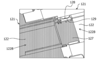
- FIG. 7 is a perspective view of the support member 120 from the lower surface 122B side of the main body 122 of the support case 121 when the plurality of support cases 121 are connected. As shown in FIG. 7, the slide portion 127 of the one support case 121 (the left side support case 121 in FIG.
- the protrusion 128 of the one support case 121 is fitted into the elongated hole 129 of the other support case 121, so that a state in which the plurality of support cases 121 are coupled (hereinafter, referred to as a coupled state) is obtained. Maintained.
- FIG. 8 is a plan view of the support member 120 according to the embodiment. As shown in FIG. 8, in the connected state, one support case 121 (the left support case 121 in FIG.
- the slide portion 127 of the one support case 121 is pulled out from the main body portion 122 of the other support case 121
- at least a part of the slide portion 127 of the one support case 121 is made into the other support case 121. It can also be housed in the main body 122 of the.
- the interval (distance) between the one support case 121 and the other support case 121 is narrowed, and a part of the slide portion 127 of the one support case 121 is pulled out from the main body portion 122 of the other support case 121.
- the length of the support member 120 becomes shorter than that in the state.
- FIG. 9 is a plan view of the support member 120 according to the embodiment.
- FIG. 9A shows the support member 120 in a state where a part of the slide portion 127 of the one support case 121 is pulled out from the main body portion 122 of the other support case 121.
- FIG. 9B shows the support member 120 in a state where the entire slide portion 127 of the one support case 121 is accommodated in the main body portion 122 of the other support case 121.
- the length of the support member 120 shown in FIG. 9 (A) is longer than the length of the support member 120 shown in FIG. 9 (B).
- the length of the support member 120 can be adjusted by storing the support member 120 in the main body 122. Therefore, the support member 120 expands and contracts in the longitudinal direction of the support member 120.
- the support cases 121B and 121C also have the same configuration as the support case 121A. The whole or a part of the slide portion 127 of the support case 121B can be housed in the main body portion 122 of the support case 121A.
- a part of the slide portion 127 of the support case 121B can be pulled out from the main body portion 122 of the support case 121A. All or part of the slide portion 127 of the support case 121A can be housed in the main body portion 122 of the support case 121C. Further, a part of the slide portion 127 of the support case 121A can be pulled out from the main body portion 122 of the support case 121C.
- Dimension variation of the battery 110 occurs in the longitudinal direction of the battery 110, that is, the arrangement direction (stacking direction) of the plurality of cells 111.
- the support member 120 when the support member 120 is attached to the battery 110, the length of the support member 120 can be adjusted according to the dimensional variation of the battery 110. Therefore, the support member 120 can be attached to the battery 110 in consideration of the dimensional variation of the battery 110. That is, when the support member 120 is attached to the battery 110, the support member 120 can be expanded and contracted to absorb variations in the size of the battery 110. Further, when the cell 111 expands or the battery 110 vibrates after the support member 120 is attached to the battery 110, the support member 120 expands and contracts, so that the stress concentration of the support member 120 can be relaxed.
- the bus bars 141 and 142 are mounted on the support member 120 in a state that they can be moved in parallel. Therefore, the bus bars 141, 142 are mounted on the mounting portion 123 so as to be movable in the direction in which the plurality of support cases 121 are arranged.
- the bus bars 141 and 142 can be moved in the arrangement direction of the cells 111 with the support member 120 attached to the battery 110. Therefore, after attaching the support member 120 to the battery 110, when attaching the bus bars 141 and 142 to the battery 110, move the bus bars 141 and 142 in the arrangement direction of the plurality of cells 111 according to the manufacturing tolerance of the thickness of each cell 111.
- the bus bars 141 and 142 can be attached to the battery 110 in consideration of the manufacturing tolerance of the thickness of each cell 111. As described above, according to the battery module 100, the manufacturing tolerance of the thickness of each cell 111 can be absorbed. Further, since the bus bars 141 and 142 are not fixed to the support member 120, the stress concentration of the support member 120 when the expansion of the cell 111 or the vibration of the battery 110 occurs can be relaxed.
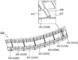
- FIG. 10 is a perspective view of the support member 120 according to the embodiment.
- a hinge 126 having flexibility is provided between the main body 122 of the support case 121 and the slide 127.
- the hinge 126 connects the main body 122 and the slide 127.
- the hinge 126 bends to change the angle of the slide part 127 with respect to the main body part 122.
- the slide portion 127 of the one support case 121 is housed in the main body portion 122 of the other support case 121, when an external force is applied to the one support case 121 or the other support case 121, the other support case 121 with respect to the other support case 121.
- the angle of the support case 121 changes.
- the support member 120 can be attached to the battery 110 while bending or bending the support member 120, and the support member 120 can be easily attached to the battery 110. Therefore, the time required to attach the support member 120 to the battery 110 can be shortened. Further, when the cell 111 expands or the battery 110 vibrates, the support member 120 bends or curves, so that stress concentration of the support member 120 can be relieved.
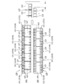
- FIG. 11 is a cross-sectional view of the battery module 100 according to the embodiment.
- FIG. 11 shows a part of the cross section of the battery module 100.
- the FPC 150 may be partially curved and the FPC 150 may be placed on the support member 120.
- the FPC 150 has a flat portion 151 and a bending portion 152.
- the flexible portion 152 of the FPC 150 is flexed with respect to the flat portion 151 of the FPC 150.
- the support member 120 is extended, the bending of the bending portion 152 of the FPC 150 is reduced, so that the FPC 150 can follow the extension of the support member 120. Therefore, even when the support member 120 is extended, the size of the FPC 150 matches the size of the support member 120.
- the FPC 150 may be placed on the support member 120 so that the bending portion 152 of the FPC 150 is located directly above the hinge 126 of the support member 120. Since the hinge 126 projects above the main body 122, when the flat portion 151 of the FPC 150 is located directly above the hinge 126 of the support member 120, the flat portion 151 of the FPC 150 may rise. Since the flexible portion 152 of the FPC 150 is located directly above the hinge 126 of the support member 120, it is possible to prevent the flat portion 151 of the FPC 150 from being raised.
- monitoring device 20 voltage monitoring device main body 30 temperature measuring device main body 100 battery module 110 battery 111 cell 112 positive electrode terminal 113 negative electrode terminal 120 support members 121, 121A, 121B, 121C support case 122 main body part 123 mounting part 124 pressing part 125 pressing part 126 Hinge 127 Slide part 128 Projection parts 129, 143 Oblong holes 141, 141A, 141B, 142 Bus bar 150 FPC 151 Flat part 152 Flexible part 170 Connector
Landscapes
- Chemical & Material Sciences (AREA)
- Chemical Kinetics & Catalysis (AREA)
- Electrochemistry (AREA)
- General Chemical & Material Sciences (AREA)
- Engineering & Computer Science (AREA)
- Manufacturing & Machinery (AREA)
- Battery Mounting, Suspending (AREA)
- Connection Of Batteries Or Terminals (AREA)
Abstract
バッテリの寸法のバラツキを考慮した支持部材及びバッテリモジュールを提供すると共に、支持部材の応力集中を緩和する。 複数の支持ケース121が連結されており、隣り合う一方の支持ケース121のスライド部127が、他方の支持ケース121の本体部122にスライド可能に収容されており、一方の支持ケース121のスライド部127の一部を他方の支持ケース121の本体部122から引き出すことにより、一方の支持ケース121と他方の支持ケース121との間隔が広がり、一方の支持ケース121のスライド部127の少なくとも一部を他方の支持ケース121の本体部122に収容することにより、一方の支持ケース122と他方の支持ケース122との間隔が狭まる。
Description
本発明は、支持部材及びバッテリモジュールに関する。
電気自動車などに搭載されるバッテリにおいては、バッテリの電圧を監視するために、電圧監視装置が設けられている。この電圧監視装置は、バッテリに取り付けられる電圧監視ユニットを備えている。そして、この電圧監視ユニットは、バッテリにおける各電極に電気的に接続される複数の配線を有するフレキシブルプリント配線板を備えている。バッテリは、複数のセルから構成されており、複数のセル間はバスバと呼ばれる金属部材によって電気的に接続されている。フレキシブルプリント配線板及びバスバは、カバーによって支持されている。カバーは、バッテリに取り付けられる。
セルの厚みには製造公差が存在する。また、複数のセルを積層してバッテリを組み立てる場合、組み立て公差が発生する。したがって、バッテリの寸法(セルの積層方向の長さ)にバラツキが発生する。バッテリの寸法のバラツキは、セルの積総数に応じて大きくなる。従来技術では、カバーが一体的であるため、カバーをバッテリに取り付けることが困難になる場合がある。また、セルの発熱によりセルが膨張すると、バッテリにカバーを取り付けた後に、カバーに応力が集中し、カバーが損傷する可能性がある。更に、カバーに振動が発生した際、カバーの応力集中を緩和することも望まれている。
平野優子,辻朋郁,矢板久佳,平井宏樹、「セル数変更可能な高圧電池配線モジュール」、2015年1月・SEIテクニカルレビュー・第186号、p.41-44
本発明の目的は、バッテリの寸法のバラツキを考慮した支持部材及びバッテリモジュールを提供すると共に、支持部材の応力集中を緩和することを目的とする。
本発明は、上記課題を解決するために以下の手段を採用した。
本発明の支持部材は、
複数のセルを配列して構成されたバッテリに取り付ける支持部材であって、
前記複数のセルを電気的に接続する導電性部材を搭載可能な搭載部と、前記搭載部が接続された本体部と、前記本体部に接続されたスライド部と、を有する複数の支持ケースを備え、
前記複数の支持ケースが連結されており、
前記複数の支持ケースのうちの隣り合う一方の支持ケースの前記スライド部が、前記複数の支持ケースのうちの隣り合う他方の支持ケースの前記本体部にスライド可能に収容されており、
前記一方の支持ケースの前記スライド部の一部を前記他方の支持ケースの前記本体部から引き出すことにより、前記一方の支持ケースと前記他方の支持ケースとの間隔が広がり、
前記一方の支持ケースの前記スライド部の少なくとも一部を前記他方の支持ケースの前記本体部に収容することにより、前記一方の支持ケースと前記他方の支持ケースとの間隔が狭まることを特徴とする。
また、本発明のバッテリモジュールは、
複数のセルを配列して構成されたバッテリと、
前記複数のセルを電気的に接続する導電性部材が搭載された搭載部と、前記搭載部が接続された本体部と、前記本体部に接続されたスライド部と、が設けられた複数の支持ケースを有し、前記バッテリに取り付けられた支持部材と、
を備え、
前記複数の支持ケースが連結されており、
前記複数の支持ケースのうちの隣り合う一方の支持ケースの前記スライド部が、前記複数の支持ケースのうちの隣り合う他方の支持ケースの前記本体部にスライド可能に収容されており、
前記一方の支持ケースの前記スライド部の一部を前記他方の支持ケースの前記本体部から引き出すことにより、前記一方の支持ケースと前記他方の支持ケースとの間隔が広がり、
前記一方の支持ケースの前記スライド部の少なくとも一部を前記他方の支持ケースの前記本体部に収容することにより、前記一方の支持ケースと前記他方の支持ケースとの間隔が狭まることを特徴とする。
これらの発明においては、複数の支持ケースが連結されており、複数の支持ケースのうちの隣り合う一方の支持ケースのスライド部が、複数の支持ケースのうちの隣り合う他方の支持ケースの本体部にスライド可能に収容されている。一方の支持ケースのスライド部の一部を他方の支持ケースの本体部から引き出すことにより、一方の支持ケースと他方の支持ケースとの間隔が広がる。また、一方の支持ケースのスライド部の少なくとも一部を他方の支持ケースの本体部に収容することにより、一方の支持ケースと他方の支持ケースとの間隔が狭まる。一方の支持ケースと他方の支持ケースとの間隔が広がることで、支持部材の長さが長くなり、一方の支持ケースと他方の支持ケースとの間隔が狭まることで、支持部材の長さが短くなる。このように、一方の支持ケース121のスライド部の一部を他方の支持ケースの本体部から引き出したり、一方の支持ケースのスライド部の少なくとも一部を他方の支持ケースの本体部に収容したりすることにより、支持部材の長さを調整することができる。したがって、バッテリに支持部材を取り付ける際、バッテリの寸法のバラツキに応じて支持部材の長さを調整することできる。このため、バッテリの寸法のバラツキを考慮して、バッテリに支持部材120を取り付けることができる。また、バッテリに支持部材を取り付けた後にセルの膨張やバッテリの振動が発生した際、支持部材が伸縮することで、支持部材の応力集中を緩和することができる。
本発明の支持部材及び本発明のバッテリモジュールにおいて、前記複数の支持ケースの前記本体部と前記スライド部とがヒンジを介して接続されており、前記一方の支持ケースの前記本体部に対する前記スライド部の角度が変化することにより、前記一方の支持ケースに対する前記他方の支持ケースの角度が変化してもよい。
これにより、支持部材を屈曲又は湾曲させながら、バッテリに支持部材を取り付けることができ、バッテリに対して支持部材を容易に取り付けることができる。
本発明の支持部材及び本発明のバッテリモジュールにおいて、導電性部材が、複数の支持ケースの並び方向に向かって移動可能に搭載部に搭載されてもよい。
これにより、バッテリに支持部材を取り付けた状態で、導電性部材を複数の支持ケースの並び方向に動かすことができるため、各セルの厚みの製造公差に応じて導電性部材を複数のセルの配列方向に動かすことができる。
本発明の支持部材及び本発明のバッテリモジュールにおいて、複数の支持ケースのそれぞれに導電性部材を複数搭載可能であってもよい。
これにより、複数の導電性部材が搭載された支持ケースを用いて支持部材を伸縮することができる。
本発明のバッテリモジュールは、平坦部及び撓み部を有し、前記支持部材に支持されたフレキシブルプリント配線板を備え、前記撓み部が前記ヒンジの直上に位置していてもよい。
これにより、フレキシブルプリント配線板の平坦部における隆起の発生を抑止することができる。
本発明によれば、バッテリの寸法のバラツキを考慮した支持部材及びバッテリモジュールにおいて、支持部材の応力集中を緩和することができる。
以下に図面を参照して、この発明を実施するための形態を、例示的に詳しく説明する。
ただし、実施形態に記載されている構成部品の寸法、材質、形状、その他の相対位置などは、特に特定的な記載がない限りは、この発明の範囲をそれらのみに限定する趣旨のものではない。
ただし、実施形態に記載されている構成部品の寸法、材質、形状、その他の相対位置などは、特に特定的な記載がない限りは、この発明の範囲をそれらのみに限定する趣旨のものではない。
図1~図11を参照して、実施形態に係る監視装置、バッテリモジュール及び支持部材について説明する。
<監視装置及びバッテリモジュール>
図1~図3を参照して、実施形態に係る監視装置10及びバッテリモジュール100について説明する。図1は、実施形態に係る監視装置10及びバッテリモジュール100の平面図である。図2は、実施形態に係るバッテリモジュール100の構成を示す斜視図である。図3は、実施形態に係る監視装置10及びバッテリモジュール100の側面図である。監視装置10は、電圧監視装置本体20と、温度測定装置本体30とを備えている。図1に示す例では、電圧監視装置本体20と、温度測定装置本体30とが一体化されている。バッテリモジュール100は、バッテリ110と、支持部材120と、複数のバスバ141、142と、フレキシブルプリント配線板(以下、FPCと称する)150とを備える。また、バッテリモジュール100は、監視装置10に接続されるコネクタ170を備える。監視装置10は、バッテリ110の電圧を監視すると共に、バッテリ110の温度を測定する。支持部材120は、バスバ141、142及びFPC150を支持する。バッテリ110に支持部材120を取り付ける際、バッテリ110上に支持部材120を配置する。支持部材120は、支持部材120をバッテリ110に取り付けるための取り付け部材を有している。バッテリ110は、複数のセル111を配列(積層)して構成されている。図1~図3に示すバッテリモジュール100の構成例では、セル111の長手方向と直交する方向(以下、セル111の配列方向と称する)に向かって複数のセル111が並んで配置されている。
複数のセル111のそれぞれは、正極端子112及び負極端子113を備える。正極端子112及び負極端子113は、ボルト形状を有しており、セル111の上面から突出している。隣り合うセル111において、一方のセル111の正極端子112と他方のセル111の負極端子113とがセル111の配列方向に並んでいる。したがって、バッテリ110では、セル111の配列方向に向かって複数の正極端子112と複数の負極端子113とが交互に並んでいる。隣り合うセル111の正極端子112と負極端子113とがバスバ141によって電気的に接続されている。したがって、複数のセル111は、隣り合う正極端子112と負極端子113とがバスバ141によって電気的に接続されることで直列に接続されるように構成される。バスバ141、142は、導電性部材である。導電性部材として板状金属が例示される。セル111の個数は、図1~図3に示すバッテリモジュール100の構成例に限定されず、例えば、バッテリ110の出力電圧に応じて決定してもよい。バスバ141、142は、長孔143を有している。バスバ141、142を、バッテリ110に取り付ける際、バスバ141、142の長孔143に正極端子112、負極端子113を挿通する。なお、長孔143に限定されず、バスバ141、142は、丸孔を有してもよい。バスバ141、142の丸孔に正極端子112、負極端子113を挿通してもよい。
FPC150は、柔軟性を有するフィルムと、複数の配線とを備えている。複数の配線は、例えば、銅箔などにより構成される。複数の配線のうちの一部を電圧監視用配線に用いてもよいし、複数の配線のうちの他の一部を温度測定用配線に用いてもよい。この場合、電圧監視用配線及び温度測定用配線がコネクタ170に接続される。
<支持部材>
図4を参照して、実施形態に係る支持部材120について説明する。図4は、実施形態に係る支持部材120の斜視図である。支持部材120は、複数の支持ケース(筺体)121から構成される。複数の支持ケース121を相互に連結することで、複数の支持ケース121を繋ぐことができる。図4の(A)は、複数の支持ケース121を連結する前の状態を示しており、図4の(B)は、複数の支持ケース121を連結した後の状態を示している。図4に示すように、複数の支持ケース121Aは同一形状であり、支持ケース121Bの形状は、支持ケース121A、121Cの形状と異なり、支持ケース121Cの形状は、支持ケース121A、121Bの形状と異なる。
図4を参照して、実施形態に係る支持部材120について説明する。図4は、実施形態に係る支持部材120の斜視図である。支持部材120は、複数の支持ケース(筺体)121から構成される。複数の支持ケース121を相互に連結することで、複数の支持ケース121を繋ぐことができる。図4の(A)は、複数の支持ケース121を連結する前の状態を示しており、図4の(B)は、複数の支持ケース121を連結した後の状態を示している。図4に示すように、複数の支持ケース121Aは同一形状であり、支持ケース121Bの形状は、支持ケース121A、121Cの形状と異なり、支持ケース121Cの形状は、支持ケース121A、121Bの形状と異なる。
図5及び図6を参照して、実施形態に係る支持ケース121について説明する。図5及び図6は、実施形態に係る支持ケース121Aの平面図である。支持ケース121Aには、複数のバスバ141が搭載される。支持ケース121Aによって複数のバスバ141が支持されている。支持ケース121Aは、本体部122と、本体部122に接続された複数の搭載部123とを有する。複数の搭載部123のそれぞれに一つのバスバ141が搭載可能である。図5は、支持ケース121Aに複数のバスバ141を搭載する前の状態を示しており、図6は、支持ケース121Aに複数のバスバ141を搭載した後の状態を示している。また、支持ケース121Aは、本体部122と、本体部122に接続された一つの搭載部123とを有してもよい。この場合、一つの搭載部123に複数のバスバ141を搭載してもよい。なお、支持ケース121B、121Bは、支持ケース121Aと同様に、本体部122と、本体部122に接続された複数の搭載部123とを有する。支持ケース121B、121Cには、支持ケース121Aと同様に、複数のバスバ141が搭載される。支持ケース121B、121Cのそれぞれには、一つのバスバ142が搭載される。また、支持ケース121B、121Cは、本体部122と、本体部122に接続された一つの搭載部123とを有してもよい。この場合、一つの搭載部123に複数のバスバ141と一つのバスバ142を搭載してもよい。
図6に示すように、1つの支持ケース121Aに対して6つのバスバ141が搭載されているが、支持ケース121Aに搭載されるバスバ141の個数は限定されない。支持ケース121Aには少なくとも2つのバスバ141が搭載される。図6に示す構成例では、3つのバスバ141Aが連続して並ぶようにして支持ケース121Aに搭載され、3つのバスバ141Bが連続して並ぶようにして支持ケース121Aに搭載されている。本体部122の上面122Aの法線方向から見て、3つのバスバ141Aと3つのバスバ141Bとの間に、本体部122が挟まれるようにして配置されている。このように、支持ケース121Aに搭載された複数のバスバ141のうちの一部と他の一部とが、本体部122を隔てて配置されている。搭載部123内に押さえ部124及び押圧部125が設けられている。搭載部123にバスバ141を搭載すると、押さえ部124がバスバ141の上面に当接し、押圧部125がバスバ141の側面及び下面に当接する。押圧部125は可撓性を有している。バスバ141が移動可能な程度に、押圧部125がバスバ141を本体部122及び押さえ部124に向けて押圧する。このように、バスバ141を平行方向に動かすことができる状態で、バスバ141が搭載部123に搭載されている。バスバ141と同様に、バスバ142を平行方向に動かすことができる状態で、バスバ142が搭載部123に搭載されている。なお、複数の支持ケース121を連結させた場合、バスバ141、142が、複数の支持ケース121の並び方向に向かって移動可能に支持ケース121に搭載される。また、バッテリ110に支持部材120を取り付けた場合、バッテリ110に支持部材120を取り付けた状態で、バスバ141、142をセル111の配列方向に向かって動かすことができる。
支持ケース121は、ヒンジ126及びスライド部127を有する。スライド部127は、ヒンジ126を介して本体部122に接続されている。複数の支持ケース121が連結されており、複数の支持ケース121のうちの隣り合う一方の支持ケース121のスライド部127が、複数の支持ケース121のうちの隣り合う他方の支持ケース121の本体部122にスライド可能に収納されている。図7は、複数の支持ケース121を連結した場合において、支持ケース121の本体部122の下面122B側からの支持部材120の斜視図である。図7に示すように、一方の支持ケース121(図7の左側の支持ケース121)のスライド部127が、他方の支持ケース121(図7の右側の支持ケース121)の本体部122に収納されている。一方の支持ケース121のスライド部127が、他方の支持ケース121の本体部122に収納されると、一方の支持ケース121のスライド部127に形成された突起部128が、他方の支持ケース121の本体部122の下面122Bに形成された長孔129に嵌め込まれる。このように、一方の支持ケース121の突起部128が、他方の支持ケース121の長孔129に嵌め込まれることにより、複数の支持ケース121が連結された状態(以下、連結状態と表記する)が維持される。
連結状態において、一方の支持ケース121を他方の支持ケース121から離れる方向に引くと、一方の支持ケース121の突起部128が他方の支持ケース121の長孔129をスライド移動し、長孔129の内周面に当接する。この場合、一方の支持ケース121のスライド部127が他方の支持ケース121の本体部122内をスライドし、一方の支持ケース121のスライド部127の一部が、他方の支持ケース121の本体部122から引き出された状態になる。図8は、実施形態に係る支持部材120の平面図である。図8に示すように、連結状態において、一方の支持ケース121(図8の左側の支持ケース121)を他方の支持ケース121(図8の右側の支持ケース121)から離れる方向に引く。そうすると、一方の支持ケース121のスライド部127の一部が、他方の支持ケース121の本体部122から引き出される。これにより、一方の支持ケース121と他方の支持ケース121との間隔(距離)が広がり、一方の支持ケース121のスライド部127の全部が他方の支持ケース121の本体部122に収容された状態よりも、支持部材120の長さが長くなる。他方の支持ケース121の本体部122から一方の支持ケース121のスライド部127の引き出された部分の長さに応じて、支持部材120の長さが長くなる。また、一方の支持ケース121のスライド部127の一部が他方の支持ケース121の本体部122から引き出された状態において、一方の支持ケース121のスライド部127の少なくとも一部を他方の支持ケース121の本体部122に収容することもできる。この場合、一方の支持ケース121と他方の支持ケース121との間隔(距離)が狭くなり、一方の支持ケース121のスライド部127の一部が他方の支持ケース121の本体部122から引き出された状態よりも、支持部材120の長さが短くなる。
図9は、実施形態に係る支持部材120の平面図である。図9の(A)は、一方の支持ケース121のスライド部127の一部が、他方の支持ケース121の本体部122から引き出された状態の支持部材120を示す。図9の(B)は、一方の支持ケース121のスライド部127の全部が、他方の支持ケース121の本体部122に収容された状態の支持部材120を示す。図9の(A)に示す支持部材120の長さが、図9の(B)に示す支持部材120の長さよりも長い。このように、一方の支持ケース121のスライド部127の一部を他方の支持ケース121の本体部122から引き出したり、一方の支持ケース121のスライド部127の全部又は一部を他方の支持ケース121の本体部122に収容したりすることにより、支持部材120の長さを調整することができる。したがって、支持部材120の長手方向に支持部材120が伸縮する。なお、支持ケース121B、121Cについても、支持ケース121Aと同様の構成を有する。支持ケース121Bのスライド部127の全部又は一部を支持ケース121Aの本体部122に収容することが可能である。また、支持ケース121Bのスライド部127の一部を支持ケース121Aの本体部122から引き出すことが可能である。支持ケース121Aのスライド部127の全部又は一部を支持ケース121Cの本体部122に収容することが可能である。また、支持ケース121Aのスライド部127の一部を支持ケース121Cの本体部122から引き出すことが可能である。
バッテリ110の長手方向、すなわち、複数のセル111の配列方向(積層方向)においてバッテリ110の寸法のバラツキが発生する。バッテリモジュール100では、バッテリ110に支持部材120を取り付ける際、バッテリ110の寸法のバラツキに応じて支持部材120の長さを調整することできる。このため、バッテリ110の寸法のバラツキを考慮して、バッテリ110に支持部材120を取り付けることができる。すなわち、バッテリ110に支持部材120を取り付ける際、支持部材120を伸縮することにより、バッテリ110の寸法のバラツキを吸収することができる。また、バッテリ110に支持部材120を取り付けた後にセル111の膨張やバッテリ110の振動が発生した際、支持部材120が伸縮することで、支持部材120の応力集中を緩和することができる。
バスバ141、142を平行方向に動かすことができる状態で、支持部材120に搭載されている。したがって、バスバ141、142が、複数の支持ケース121の並び方向に向かって移動可能に搭載部123に搭載される。バッテリ110に支持部材120を取り付けた場合、バッテリ110に支持部材120を取り付けた状態で、バスバ141、142をセル111の配列方向に動かすことができる。そのため、バッテリ110に支持部材120を取り付けた後、バッテリ110にバスバ141、142を取り付ける際、各セル111の厚みの製造公差に応じてバスバ141、142を複数のセル111の配列方向に動かすことができる。したがって、各セル111の厚みの製造公差を考慮して、バッテリ110にバスバ141、142を取り付けることができる。このように、バッテリモジュール100によれば、各セル111の厚みの製造公差を吸収することができる。また、バスバ141、142は、支持部材120に固定されていないため、セル111の膨張やバッテリ110の振動が発生した際における支持部材120の応力集中を緩和することができる。
図10は、実施形態に係る支持部材120の斜視図である。図10に示すように、支持ケース121の本体部122とスライド部127との間に、屈曲性を有するヒンジ126が設けられている。ヒンジ126は、本体部122とスライド部127を繋いでいる。本体部122又はスライド部127に外力が加わった場合、ヒンジ126が屈曲することにより、本体部122に対するスライド部127の角度が変化する。一方の支持ケース121のスライド部127が他方の支持ケース121の本体部122に収容されている場合、一方の支持ケース121又は他方の支持ケース121に外力が加わると、一方の支持ケース121に対する他方の支持ケース121の角度が変化する。これにより、支持部材120を屈曲又は湾曲させながら、バッテリ110に支持部材120を取り付けることができ、バッテリ110に対して支持部材120を容易に取り付けることができる。そのため、バッテリ110に支持部材120を取り付ける際の時間を短縮することができる。また、セル111の膨張やバッテリ110の振動が発生した際に、支持部材120が屈曲又は湾曲することにより、支持部材120の応力集中を緩和することができる。
図11は、実施形態に係るバッテリモジュール100の断面図である。図11には、バッテリモジュール100の断面の一部が示されている。図11に示すように、FPC150を部分的に湾曲させて、支持部材120にFPC150を載置してもよい。FPC150は、平坦部151及び撓み部152を有している。FPC150の撓み部152は、FPC150の平坦部151に対して撓んでいる。支持部材120を伸ばしたときに、FPC150の撓み部152の撓みが小さくなることで、支持部材120の伸長に対してFPC150が追従することができる。したがって、支持部材120を伸ばした場合であっても、支持部材120のサイズに対してFPC150のサイズが合う。また、FPC150の撓み部152が、支持部材120のヒンジ126の直上に位置するように、支持部材120にFPC150を載置してもよい。ヒンジ126は、本体部122よりも上方に突出しているため、FPC150の平坦部151が支持部材120のヒンジ126の直上に位置する場合、FPC150の平坦部151が隆起する可能性がある。FPC150の撓み部152が、支持部材120のヒンジ126の直上に位置することで、FPC150の平坦部151における隆起の発生を抑止することができる。
10 監視装置
20 電圧監視装置本体
30 温度測定装置本体
100 バッテリモジュール
110 バッテリ
111 セル
112 正極端子
113 負極端子
120 支持部材
121、121A、121B、121C 支持ケース
122 本体部
123 搭載部
124 押さえ部
125 押圧部
126 ヒンジ
127 スライド部
128 突起部
129、143 長孔
141、141A、141B、142 バスバ
150 FPC
151 平坦部
152 撓み部
170 コネクタ
20 電圧監視装置本体
30 温度測定装置本体
100 バッテリモジュール
110 バッテリ
111 セル
112 正極端子
113 負極端子
120 支持部材
121、121A、121B、121C 支持ケース
122 本体部
123 搭載部
124 押さえ部
125 押圧部
126 ヒンジ
127 スライド部
128 突起部
129、143 長孔
141、141A、141B、142 バスバ
150 FPC
151 平坦部
152 撓み部
170 コネクタ
Claims (9)
- 複数のセルを配列して構成されたバッテリに取り付ける支持部材であって、
前記複数のセルを電気的に接続する導電性部材を搭載可能な搭載部と、前記搭載部が接続された本体部と、前記本体部に接続されたスライド部と、を有する複数の支持ケースを備え、
前記複数の支持ケースが連結されており、
前記複数の支持ケースのうちの隣り合う一方の支持ケースの前記スライド部が、前記複数の支持ケースのうちの隣り合う他方の支持ケースの前記本体部にスライド可能に収容されており、
前記一方の支持ケースの前記スライド部の一部を前記他方の支持ケースの前記本体部から引き出すことにより、前記一方の支持ケースと前記他方の支持ケースとの間隔が広がり、
前記一方の支持ケースの前記スライド部の少なくとも一部を前記他方の支持ケースの前記本体部に収容することにより、前記一方の支持ケースと前記他方の支持ケースとの間隔が狭まることを特徴とする支持部材。 - 前記複数の支持ケースの前記本体部と前記スライド部とがヒンジを介して接続されており、
前記一方の支持ケースの前記本体部に対する前記スライド部の角度が変化することにより、前記一方の支持ケースに対する前記他方の支持ケースの角度が変化することを特徴とする請求項1に記載の支持部材。 - 前記導電性部材が、前記複数の支持ケースの並び方向に向かって移動可能に前記搭載部に搭載されていることを特徴とする請求項1又は2に記載の支持部材。
- 前記複数の支持ケースのそれぞれに前記導電性部材を複数搭載可能であることを特徴とする請求項1から3の何れか一項に記載の支持部材。
- 複数のセルを配列して構成されたバッテリと、
前記複数のセルを電気的に接続する導電性部材が搭載された搭載部と、前記搭載部が接続された本体部と、前記本体部に接続されたスライド部と、が設けられた複数の支持ケースを有し、前記バッテリに取り付けられた支持部材と、
を備え、
前記複数の支持ケースが連結されており、
前記複数の支持ケースのうちの隣り合う一方の支持ケースの前記スライド部が、前記複数の支持ケースのうちの隣り合う他方の支持ケースの前記本体部にスライド可能に収容されており、
前記一方の支持ケースの前記スライド部の一部を前記他方の支持ケースの前記本体部から引き出すことにより、前記一方の支持ケースと前記他方の支持ケースとの間隔が広がり、
前記一方の支持ケースの前記スライド部の少なくとも一部を前記他方の支持ケースの前記本体部に収容することにより、前記一方の支持ケースと前記他方の支持ケースとの間隔が狭まることを特徴とするバッテリモジュール。 - 前記複数の支持ケースの前記本体部と前記スライド部とがヒンジを介して接続されており、
前記一方の支持ケースの前記本体部に対する前記スライド部の角度が変化することにより、前記一方の支持ケースに対する前記他方の支持ケースの角度が変化することを特徴とする請求項5に記載のバッテリモジュール。 - 撓み部を有し、前記支持部材に支持されたフレキシブルプリント配線板を備え、
前記撓み部が前記ヒンジの直上に位置していることを特徴とする請求項6に記載のバッテリモジュール。 - 前記導電性部材が、前記複数の支持ケースの並び方向に向かって移動可能に前記搭載部に搭載されていることを特徴とする請求項5から7の何れか一項に記載のバッテリモジュール。
- 前記複数の支持ケースのそれぞれに前記導電性部材が複数搭載されていることを特徴とする請求項5から8の何れか一項に記載のバッテリモジュール。
Priority Applications (3)
| Application Number | Priority Date | Filing Date | Title |
|---|---|---|---|
| US17/276,084 US20220045396A1 (en) | 2018-11-20 | 2019-09-03 | Support member and battery module |
| DE112019005800.2T DE112019005800T5 (de) | 2018-11-20 | 2019-09-03 | Trägerbauglied und batteriemodul |
| CN201980052834.8A CN112640189B (zh) | 2018-11-20 | 2019-09-03 | 支承构件以及蓄电池模块 |
Applications Claiming Priority (2)
| Application Number | Priority Date | Filing Date | Title |
|---|---|---|---|
| JP2018-217528 | 2018-11-20 | ||
| JP2018217528A JP7184606B2 (ja) | 2018-11-20 | 2018-11-20 | 支持部材及びバッテリモジュール |
Publications (1)
| Publication Number | Publication Date |
|---|---|
| WO2020105244A1 true WO2020105244A1 (ja) | 2020-05-28 |
Family
ID=70773183
Family Applications (1)
| Application Number | Title | Priority Date | Filing Date |
|---|---|---|---|
| PCT/JP2019/034514 WO2020105244A1 (ja) | 2018-11-20 | 2019-09-03 | 支持部材及びバッテリモジュール |
Country Status (5)
| Country | Link |
|---|---|
| US (1) | US20220045396A1 (ja) |
| JP (1) | JP7184606B2 (ja) |
| CN (1) | CN112640189B (ja) |
| DE (1) | DE112019005800T5 (ja) |
| WO (1) | WO2020105244A1 (ja) |
Families Citing this family (3)
| Publication number | Priority date | Publication date | Assignee | Title |
|---|---|---|---|---|
| KR20230102738A (ko) * | 2021-12-30 | 2023-07-07 | 삼성에스디아이 주식회사 | 버스 바 홀더, 버스 바 조립체 및 전지 모듈 |
| CN114039150B (zh) * | 2022-01-12 | 2022-05-06 | 新乡市鸿晟能源有限公司 | 一种通信离网系统应急电源后备锂电池组 |
| CN115882152B (zh) * | 2023-02-08 | 2023-05-23 | 合肥联宝信息技术有限公司 | 一种电池组件及具有该电池组件的电子设备 |
Citations (3)
| Publication number | Priority date | Publication date | Assignee | Title |
|---|---|---|---|---|
| JP2013016379A (ja) * | 2011-07-05 | 2013-01-24 | Auto Network Gijutsu Kenkyusho:Kk | 電池配線モジュール |
| JP2013054940A (ja) * | 2011-09-05 | 2013-03-21 | Toyota Motor Corp | 電池接続ユニット及び電源装置 |
| JP2017059391A (ja) * | 2015-09-16 | 2017-03-23 | 株式会社オートネットワーク技術研究所 | 配線モジュール |
Family Cites Families (15)
| Publication number | Priority date | Publication date | Assignee | Title |
|---|---|---|---|---|
| JPS5232187A (en) | 1975-09-04 | 1977-03-11 | Yoshio Konaka | Eccentric device of driving shaft |
| JP3127848B2 (ja) * | 1996-12-27 | 2001-01-29 | 住友電装株式会社 | プロテクタ |
| JP5500336B2 (ja) * | 2009-06-23 | 2014-05-21 | 株式会社オートネットワーク技術研究所 | 電池接続アセンブリ |
| JP2012084318A (ja) * | 2010-10-08 | 2012-04-26 | Auto Network Gijutsu Kenkyusho:Kk | バスバーモジュール |
| JP2012186063A (ja) * | 2011-03-07 | 2012-09-27 | Auto Network Gijutsu Kenkyusho:Kk | 電池接続アセンブリ |
| JP5809465B2 (ja) * | 2011-07-05 | 2015-11-11 | 矢崎総業株式会社 | 電線配索装置 |
| JP5939421B2 (ja) * | 2011-07-07 | 2016-06-22 | 株式会社オートネットワーク技術研究所 | 電池配線モジュール |
| JP5673495B2 (ja) * | 2011-11-01 | 2015-02-18 | 株式会社オートネットワーク技術研究所 | 配線モジュール |
| JP5978037B2 (ja) * | 2012-07-20 | 2016-08-24 | 矢崎総業株式会社 | バスバモジュール |
| JP6281398B2 (ja) * | 2014-04-21 | 2018-02-21 | 株式会社豊田自動織機 | 電池モジュール |
| JP6604270B2 (ja) * | 2016-06-02 | 2019-11-13 | 住友電装株式会社 | 電池配線モジュール |
| JP6699438B2 (ja) * | 2016-08-09 | 2020-05-27 | 株式会社オートネットワーク技術研究所 | 配線モジュール |
| JP6696402B2 (ja) * | 2016-10-21 | 2020-05-20 | 三菱自動車工業株式会社 | 電動車両のハーネス用プロテクタ |
| JP6585580B2 (ja) * | 2016-12-20 | 2019-10-02 | 矢崎総業株式会社 | 収容部材の連結構造及び収納ケース |
| CN207967151U (zh) * | 2018-03-30 | 2018-10-12 | 宁德时代新能源科技股份有限公司 | 电连接组件及电池模组 |
-
2018
- 2018-11-20 JP JP2018217528A patent/JP7184606B2/ja active Active
-
2019
- 2019-09-03 US US17/276,084 patent/US20220045396A1/en active Pending
- 2019-09-03 CN CN201980052834.8A patent/CN112640189B/zh active Active
- 2019-09-03 DE DE112019005800.2T patent/DE112019005800T5/de active Pending
- 2019-09-03 WO PCT/JP2019/034514 patent/WO2020105244A1/ja active Application Filing
Patent Citations (3)
| Publication number | Priority date | Publication date | Assignee | Title |
|---|---|---|---|---|
| JP2013016379A (ja) * | 2011-07-05 | 2013-01-24 | Auto Network Gijutsu Kenkyusho:Kk | 電池配線モジュール |
| JP2013054940A (ja) * | 2011-09-05 | 2013-03-21 | Toyota Motor Corp | 電池接続ユニット及び電源装置 |
| JP2017059391A (ja) * | 2015-09-16 | 2017-03-23 | 株式会社オートネットワーク技術研究所 | 配線モジュール |
Also Published As
| Publication number | Publication date |
|---|---|
| JP2020087607A (ja) | 2020-06-04 |
| CN112640189B (zh) | 2023-09-15 |
| CN112640189A (zh) | 2021-04-09 |
| US20220045396A1 (en) | 2022-02-10 |
| JP7184606B2 (ja) | 2022-12-06 |
| DE112019005800T5 (de) | 2021-08-26 |
Similar Documents
| Publication | Publication Date | Title |
|---|---|---|
| WO2020105244A1 (ja) | 支持部材及びバッテリモジュール | |
| JP7212504B2 (ja) | 接続モジュール | |
| CN102576845B (zh) | 配线部件 | |
| CN100446306C (zh) | 可再充电电池组件 | |
| US9343725B2 (en) | Bus bar module and power supply unit | |
| KR101933087B1 (ko) | 복수의 에너지 저장 요소 및 개선된 방열 수단을 구비하는 에너지 저장 모듈 및 그 에너지 저장 모듈 조립 방법 | |
| JP5618157B2 (ja) | 電池配線モジュール | |
| JP6145314B2 (ja) | バスバモジュール及び電源装置 | |
| JP2020205175A (ja) | バスバモジュール | |
| US10840496B2 (en) | Bus bar module and power supply device | |
| JP6409345B2 (ja) | 電池モジュール及び電池パック | |
| US10741817B2 (en) | Battery connection module | |
| JP5834857B2 (ja) | 電池モジュール接続装置 | |
| US20220021083A1 (en) | Connection module | |
| US20220006159A1 (en) | Connection module | |
| JP6794709B2 (ja) | 電池モジュール | |
| JP2017059481A (ja) | バスバモジュール及び電池パック | |
| CN110277518B (zh) | 汇流条模块和电池组 | |
| CN112997352B (zh) | 连接模块 | |
| JP6935208B2 (ja) | バスバー、組電池 | |
| CN114175388A (zh) | 电池模块用电连接装置 | |
| JP7308328B2 (ja) | 接続モジュール | |
| KR20140001551U (ko) | 전기 커넥터 및 전기 커넥터 조립체 | |
| JP2012129177A (ja) | カメラモジュールソケット |
Legal Events
| Date | Code | Title | Description |
|---|---|---|---|
| 121 | Ep: the epo has been informed by wipo that ep was designated in this application |
Ref document number: 19887406 Country of ref document: EP Kind code of ref document: A1 |
|
| 122 | Ep: pct application non-entry in european phase |
Ref document number: 19887406 Country of ref document: EP Kind code of ref document: A1 |