WO2020105328A1 - アルミニウム-炭素粒子複合材及びその製造方法 - Google Patents
アルミニウム-炭素粒子複合材及びその製造方法Info
- Publication number
- WO2020105328A1 WO2020105328A1 PCT/JP2019/040872 JP2019040872W WO2020105328A1 WO 2020105328 A1 WO2020105328 A1 WO 2020105328A1 JP 2019040872 W JP2019040872 W JP 2019040872W WO 2020105328 A1 WO2020105328 A1 WO 2020105328A1
- Authority
- WO
- WIPO (PCT)
- Prior art keywords
- aluminum
- carbon
- sintering
- composite material
- particles
- Prior art date
- Legal status (The legal status is an assumption and is not a legal conclusion. Google has not performed a legal analysis and makes no representation as to the accuracy of the status listed.)
- Ceased
Links
Images

Classifications
-
- C—CHEMISTRY; METALLURGY
- C22—METALLURGY; FERROUS OR NON-FERROUS ALLOYS; TREATMENT OF ALLOYS OR NON-FERROUS METALS
- C22C—ALLOYS
- C22C1/00—Making non-ferrous alloys
- C22C1/10—Alloys containing non-metals
-
- Y—GENERAL TAGGING OF NEW TECHNOLOGICAL DEVELOPMENTS; GENERAL TAGGING OF CROSS-SECTIONAL TECHNOLOGIES SPANNING OVER SEVERAL SECTIONS OF THE IPC; TECHNICAL SUBJECTS COVERED BY FORMER USPC CROSS-REFERENCE ART COLLECTIONS [XRACs] AND DIGESTS
- Y02—TECHNOLOGIES OR APPLICATIONS FOR MITIGATION OR ADAPTATION AGAINST CLIMATE CHANGE
- Y02E—REDUCTION OF GREENHOUSE GAS [GHG] EMISSIONS, RELATED TO ENERGY GENERATION, TRANSMISSION OR DISTRIBUTION
- Y02E60/00—Enabling technologies; Technologies with a potential or indirect contribution to GHG emissions mitigation
- Y02E60/10—Energy storage using batteries
Definitions
- the present invention relates to an aluminum-carbon particle composite material and a method for manufacturing the same.
- Patent Document 1 discloses a method of manufacturing such a composite material by sintering a mixture of scale-like powder made of aluminum or the like and scale-like graphite powder as carbon particles to form a composite of metal-carbon particles. A method of making a lumber is disclosed.
- the material of the cooling member or the heat dissipation member of the semiconductor device is required to have high thermal conductivity in order to obtain high cooling performance or high heat dissipation performance. Therefore, it is possible to use an aluminum-carbon particle composite material as the material of such a member.
- aluminum carbide Al 4 C 3
- Al 4 C 3 aluminum carbide
- the present invention has been made in view of the above technical background, and an object thereof is to provide an aluminum-carbon particle composite material which suppresses the formation of aluminum carbide and has high thermal conductivity, and a method for producing the same. ..
- the present invention provides the following means.
- An aluminum matrix, and carbon particles dispersed in the aluminum matrix As the aluminum material of the aluminum matrix, an aluminum alloy in which pure aluminum having a purity of 99.00 mass% or more and Mg added so that the Mg content is in the range of 20 to 300 mass ppm is used. Particle composite.
- a compound layer of Al and O is formed at the interface between the aluminum matrix and the carbon particles, 3.
- a compound layer of Al, O and C is formed at the interface between the aluminum matrix and the carbon particles, 4.
- the aluminum-carbon particle composite material as described in any one of 1 to 3 above, wherein the compound layer of Al, O and C has a thickness of 20 nm or less.
- Mg is an aluminum-carbon particle composite material according to any one of the above items 1 to 4, wherein Mg is concentrated at the interface between the aluminum matrix and the carbon particles.
- the step of sintering the first sintered material is a step of producing an aluminum foil made of the aluminum alloy, and a carbon particle-coated foil by coating a coating material containing carbon particles on the aluminum foil and drying the coating material.
- a step of manufacturing The method of manufacturing an aluminum-carbon particle composite material, wherein in the step of sintering the first sintering material, a laminated body in which a plurality of the carbon particle coating foils are laminated is sintered as the first sintering material.
- the step of sintering the second sintering material includes a step of producing aluminum particles made of the aluminum alloy, A method of manufacturing an aluminum-carbon particle composite material, wherein in the step of sintering the second sintering material, a mixture of the aluminum particles and carbon particles is sintered as the second sintering material.
- the present invention has the following effects.
- an aluminum material for an aluminum matrix of an aluminum-carbon particle composite material pure aluminum having a purity of 99.00 mass% or more is added with Mg so that the Mg content is in the range of 20 to 300 mass ppm.
- Aluminum alloy is used. Thereby, generation of aluminum carbide at the interface between the aluminum matrix and the carbon particles is suppressed. Therefore, the composite material has high thermal conductivity.
- the thermal conductivity of the composite material can be reliably increased.
- a cooler or radiator having high cooling performance or high heat radiation performance can be provided.
- the aluminum-carbon particle composite material according to any one of the previous items 1 to 6 can be manufactured.
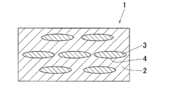
- FIG. 1 is a schematic enlarged sectional view of an aluminum-carbon particle composite material according to an embodiment of the present invention.
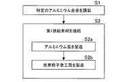
- FIG. 2 is a flowchart of a manufacturing process in the first manufacturing method of the composite material.
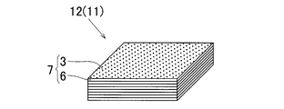
- FIG. 3 is a schematic perspective view of a laminated body as the first sintering material.
- FIG. 4 is a flowchart of a manufacturing process in the second manufacturing method of the composite material.
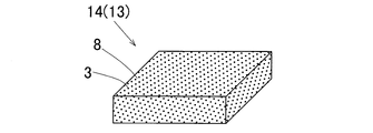
- FIG. 5 is a schematic perspective view of the mixture as the second sintering material.
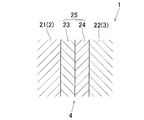
- FIG. 6 is a schematic enlarged cross-sectional view of an interface between an aluminum matrix and carbon particles in the composite material.
- an aluminum-carbon particle composite material 1 includes an aluminum matrix 2 and a large number of carbon particles 3.
- the carbon particles 3 are dispersed in the aluminum matrix 2.
- the dispersed state of the carbon particles 3 in the aluminum matrix 2 is, for example, substantially uniform.
- the term "carbon particles" is used to include carbon powder.
- carbon particles 3 At least one selected from the group consisting of graphite particles, graphene, carbon fibers and carbon nanotubes is used.
- graphite particles natural graphite particles (eg, flake graphite particles), artificial graphite particles, pyrolytic graphite particles, etc. are used, and graphite particles having high thermal conductivity (eg, flake graphite particles) are particularly suitable. Used.
- graphene single-layer graphene, multi-layer graphene, etc. are used.
- PAN-based carbon fibers, pitch-based carbon fibers, etc. are used as carbon fibers, and pitch-based carbon fibers are particularly preferably used. The reason is that the pitch-based carbon fiber has a high thermal conductivity.
- carbon nanotubes single-walled carbon nanotubes, multi-walled carbon nanotubes, vapor-grown carbon fibers (including VGCF (registered trademark)), etc. are used.
- the size of the carbon particles 3 is not limited.
- the carbon particles 3 are graphite particles, it is particularly preferable that the average length of the graphite particles in the longest axis direction is 30 ⁇ m or more.
- the upper limit of the average length of the graphite particles in the longest axis direction is not limited and is usually 3 mm.
- the length of the graphite particles in the longest axis direction means the length of the graphite particles in the longest direction.
- the average fiber length of the carbon fibers is particularly preferably 10 ⁇ m to 2 mm.
- the carbon particles 3 are carbon nanotubes
- the average length of the carbon nanotubes is particularly preferably 1 ⁇ m to 10 ⁇ m.
- the aspect ratio of the graphite particles is not limited, and particularly, the aspect ratio is preferably 30 or more.
- the upper limit of the aspect ratio is not limited and is usually 100.
- the carbon particles 3 may be heat-treated at a temperature of 2000 to 3000 ° C. in an inert atmosphere.
- an aluminum alloy in which Mg is added to pure aluminum having a purity of 99.00 mass% or more so that the Mg content is in the range of 20 to 300 mass ppm is used.
- this aluminum alloy is called a "specific aluminum alloy.”
- the aluminum purity (that is, the Al content) of the specific aluminum alloy is 98.97% by mass or more, and particularly preferably 99.00% by mass or more.
- the pure aluminum having a purity of 99.00 mass% or more is preferably selected from aluminum alloy symbol A1000 series aluminum defined by JIS (Japanese Industrial Standard). Specifically, A1N99, A1050, A1N30, A1100 and the like are preferably used as the A1000 series aluminum.
- Such pure aluminum has a purity of 99.00 mass% or more, that is, an Al content of 99.00 mass% or more, and Si (silicon), Fe (iron), Cu (copper) and Mg (magnesium). Is included.
- the Mg content of pure aluminum is specified to be 0.05 mass% (500 mass ppm) or less.
- the Mg content is 0.001 mass% (10 mass ppm) or less.
- Si, Fe, and Cu are unavoidable impurities among the above-mentioned four elements of Si, Fe, Cu, and Mg contained in addition to Al.
- These elements are impurity elements derived from components of bauxite (Al 2 O 3 , SiO 2 , Fe 2 O 3 ) which is a raw material of aluminum, an electrolytic bath for molten salt electrolysis, and electrodes. is there.
- the aluminum-carbon particle composite material 1 of the present embodiment is basically a step of preparing a specific aluminum alloy, and a step of sintering a sintering material containing an aluminum material made of the specific aluminum alloy and carbon particles. It is manufactured by.
- the aluminum-carbon particle composite material according to the present invention is not limited to being manufactured by the first and second manufacturing methods, and may be manufactured by other manufacturing methods. Good.
- the first manufacturing method of the composite material 1 includes a step S1 of preparing a specific aluminum alloy and a step S2 of sintering the first sintered material 11.
- step S1 of preparing a specific aluminum alloy Mg is added to a pure aluminum melt having a purity of 99.00 mass% or more (for example, A1000 series aluminum melt) so that the Mg content is in the range of 20 to 300 mass ppm.
- a specific aluminum alloy specifically, a molten metal of the specific aluminum alloy or a molten specific aluminum alloy
- a specific aluminum alloy casting is produced by casting this specific aluminum alloy.
- step S2 of sintering the first sintered material 11 a step S2a of manufacturing the aluminum foil 6 made of a specific aluminum alloy and a coating material (not shown) containing the carbon particles 3 are applied onto the aluminum foil 6. Then, the step S2b of manufacturing the carbon particle-coated foil 7 by drying is performed.
- the specific aluminum alloy prepared in step S1 of preparing the specific aluminum alloy is used as a material for the aluminum foil 6 to manufacture the aluminum foil 6 according to a conventional method.
- the aluminum foil 6 is manufactured by hot rolling or cold rolling (including warm rolling) a specific aluminum alloy casting.
- the hot rolling temperature is not limited and is, for example, 300 to 600 ° C.
- the annealing temperature is not limited and is, for example, 200 to 400 ° C.
- the thickness of the aluminum foil 6 is not limited and is, for example, 10 to 100 ⁇ m.
- the coating material contains carbon particles 3 as described above, and further contains a binder liquid (not shown).
- the binder liquid is basically prepared by dissolving the binder resin in a solvent. It is preferable that the carbon particles 3 and the binder liquid in the coating material are in a mixed state, and the carbon particles 3 are uniformly dispersed in the binder liquid.
- a thickener for adjusting the viscosity of the binder liquid for adjusting the viscosity of the binder liquid, a dispersant for uniformly dispersing carbon particles in the binder liquid, an additive such as a surface modifier are added as necessary. It may have been done.
- the binder resin binds the carbon particles 3 to the aluminum foil 6.
- an organic resin is usually used, and specifically, polyethylene oxide, polyvinyl alcohol, an acrylic resin or the like is used.
- the solvent dissolves the binder resin.
- a hydrophilic solvent eg, isopropyl alcohol, water
- an organic solvent or the like is used.
- a mixer such as a disper, a planetary mixer, or a bead mill is used.
- the method of applying the paint on the aluminum foil 6 and the applying apparatus are not limited.
- a three roll coater offset type
- a two roll coater direct type
- a gravure coater a knife coater
- a die coater die coater
- a spray coater a curtain coater
- a reverse roll coater and the like are used.
- the coating material is applied in layers on the aluminum foil 6 by such a coating device.
- the paint applied on the aluminum foil 6 is dried and the solvent in the paint is removed by evaporation from the paint. Thereby, the carbon particle coated foil 7 is obtained.
- the carbon particle coating foil 7 is applied in a state in which the carbon particles 3 are dispersed on the aluminum foil 6 in the surface direction. Further, the carbon particles 3 are bound to the aluminum foil 6 with a binder resin so that the carbon particles 3 do not fall off from the aluminum foil 6.
- the dispersed state of the carbon particles 3 in the surface direction of the aluminum foil 6 is preferably as uniform as possible.
- the method of drying the paint and the drying device are not limited, and for example, a drying furnace is used as the drying device.
- the drying conditions of the coating material are not limited, and may be any condition as long as the solvent in the coating material can be removed by evaporation from the coating material.
- the drying temperature is 100 to 200 ° C. and the drying time is 1 to 10 minutes.
- the coating of the paint on the aluminum foil 6 and the drying of the paint are performed by a roll-to-roll method using a winding roll (not shown) and a winding roll (not shown).
- a winding roll not shown
- a winding roll not shown
- a winding roll not shown
- a winding roll not shown
- a winding roll not shown
- the coating material is continuously applied in layers on the strip of aluminum foil 6 by the coating device.
- the coating material applied on the strip material of the aluminum foil 6 is dried by the drying device and the carbon particles 3 are bound to the binder resin by the strip material of the aluminum foil 6. Is bound in. Therefore, when the strip of aluminum foil 6 passes through the drying device, the strip of aluminum foil 6 becomes the strip of carbon particle-coated foil 7, and the strip of carbon particle-coated foil 7 is wound. It is taken up by a take-up roll.
- the laminated body 12 in which a plurality of carbon particle coating foils 7 are laminated is sintered as the first sintered material 11.
- the laminated body 12 is formed in a state in which a plurality of carbon particle coating foils 7 are laminated, for example, by laminating a plurality of carbon particle coating foils 7.
- the carbon particle-coated foil 7 is obtained, for example, by cutting a strip of the carbon particle-coated foil 7 wound on a winding roll into a predetermined shape (eg, square shape).
- the laminated body 12 is sintered by being heated while being pressurized in a predetermined direction in a predetermined sintering atmosphere (eg, non-oxidizing atmosphere, vacuum).
- a predetermined sintering atmosphere eg, non-oxidizing atmosphere, vacuum
- the plurality of carbon particle-coated foils 7 forming the laminate 12 are joined and integrated (specifically, sintered and integrated), and as a result, the above-described aluminum-carbon particle composite material 1 (see FIG. 1) is obtained. can get.
- the pressure applied to the laminated body 12 when the laminated body 12 is sintered is usually a uniaxial direction, specifically, in the thickness direction of the laminated body 12 (that is, the laminating direction of the carbon particle coating foil 7). is there.
- the sintering method of the laminated body 12 is not limited, and as the sintering method, a vacuum hot pressing method, a discharge plasma sintering method (also called a pulse current sintering method), a hot isostatic pressing method is used. (HIP method), extrusion method, rolling method and the like are used.
- the heating temperature of the laminated body 12 for sintering the laminated body 12, that is, the sintering temperature of the laminated body 12 is not limited, and is particularly higher than the melting point of a specific aluminum alloy which is an aluminum material of the aluminum foil 6. A low temperature is desirable.
- the preferable sintering conditions of the laminated body 12 when the sintering method of the laminated body 12 is the discharge plasma sintering method are as follows.
- the sintering temperature of the laminated body 12 is 450 to 660 ° C.
- the sintering time (that is, the holding time of the sintering temperature) is 10 to 300 min
- the pressure applied to the laminated body 12 is 10 to 40 MPa.
- the binder resin present in the laminate 12 heats the laminate 12 so that the temperature of the laminate 12 rises from about room temperature to the sintering temperature of the laminate 12 in the step S2 of sintering the first sintering material 11. During the process, it disappears due to sublimation, thermal decomposition, etc. and is removed from the laminate 12.
- the remaining solvent causes the temperature of the laminated body 12 to rise from about room temperature in the step S2 of sintering the first sintering material 11 to sinter the laminated body 12.
- the laminated body 12 is evaporated and removed from the laminated body 12.
- the laminate 12 is sintered as described above, so that a specific aluminum alloy which is an aluminum material of the aluminum foil 6 of the carbon particle coating foil 7 is compounded. It becomes the aluminum matrix 2 of the material 1. In the composite material 1, the aluminum matrix 2 penetrates into the gaps between the carbon particles 3, 3 so that the gaps disappear.
- the laminated body 12 is formed in a state in which a plurality of carbon particle coating foils 7 are laminated by laminating a plurality of carbon particle coating foils 7 as described above, but in the present invention,
- the second manufacturing method of the composite material 1 includes a step S11 of preparing a specific aluminum alloy and a step S12 of sintering the second sintered material 13.
- the term "aluminum particles" is used to include aluminum powder.
- the step S11 of preparing the specific aluminum alloy is performed, for example, in the same manner as the step S1 of preparing the specific aluminum alloy in the first manufacturing method of the composite material 1 described above.
- the step S12 of sintering the second sintering material 13 includes a step S12a of manufacturing the aluminum particles 8 made of a specific aluminum alloy.
- the specific aluminum alloy prepared in step S11 of preparing the specific aluminum alloy is used as a raw material of the aluminum particles 8 to manufacture the aluminum particles 8 according to a conventional method.
- the aluminum particles 8 are produced by a molten metal direct pulverization method (eg, atomizing method, molten metal stirring method, centrifugal force method), mechanical pulverization method (eg, stamp mill method, vibration mill method), or the like.
- the mixture 14 of the aluminum particles 8 and the carbon particles 3 is sintered as the second sintering material 13.
- the mixture 14 is obtained by mixing the aluminum particles 8 and the carbon particles 3.
- a green compact formed by mixing aluminum particles 8 and carbon particles 3 and compressing them is used as the mixture 14. It is desirable that the mixed state of the aluminum particles 8 and the carbon particles 3 in the mixture 14 is uniform.
- the mixture 14 is sintered by being heated while being pressurized in a predetermined direction in a predetermined sintering atmosphere (eg, non-oxidizing atmosphere, vacuum).
- a predetermined sintering atmosphere eg, non-oxidizing atmosphere, vacuum
- the direction of pressurizing the mixture 14 when sintering the mixture 14 is usually a uniaxial direction, specifically, the thickness direction of the mixture 14, for example.
- the mixture 14 is sintered as described above, so that the specific aluminum alloy, which is the aluminum material of the aluminum particles 8, is mixed with the aluminum matrix 2 of the composite material 1. Become. In the composite material 1, the aluminum matrix 2 penetrates into the gaps between the carbon particles 3, 3 so that the gaps disappear.
- the sintering method and the sintering conditions of the mixture 14 are not limited, and are, for example, the same as the sintering method and the sintering conditions of the laminate 12 in the first manufacturing method of the composite material 1 described above.
- a specific aluminum alloy is used as the aluminum material of the aluminum matrix 2, so that Al () is formed at the interface 4 between the aluminum matrix 2 and the carbon particles 3.
- a compound layer (not shown) of aluminum) and O (oxygen) and a compound layer (not shown) of Al (aluminum), O (oxygen) and C (carbon) are formed.
- Al / C interface 4 the interface 4 between the aluminum matrix 2 and the carbon particles 3
- Al—O compound layer the compound layer of Al and O
- Al—O compound layer the compound layer of Al and O
- Al—O compound layer the compound layer of Al and O
- Al—O compound layer the compound layer of C and C is referred to as "Al-O-C compound layer”.
- the Al-O compound layer is different from the Al-O-C compound layer. That is, the Al—O compound layer means an Al—O compound layer that is not combined with C or an Al—O compound layer that is not substantially combined with C.
- Both the Al—O compound layer and the Al—O—C compound layer prevent the aluminum of the aluminum matrix 2 and the carbon of the carbon particles 3 from combining with each other to form aluminum carbide (Al 4 C 3 ). Acts as a barrier layer.
- the formation of the Al—O compound layer at the Al / C interface 4 suppresses the generation of aluminum carbide at the Al / C interface 4. Therefore, the composite material 1 has high thermal conductivity. Furthermore, the formation of the Al—O—C compound layer at the Al / C interface 4 further suppresses the generation of aluminum carbide at the Al / C interface 4. Therefore, the composite material 1 has higher thermal conductivity.
- the thickness of the Al—O compound layer is preferably 20 nm or less. In this case, it is possible to reliably suppress the occurrence of cracks in the compound layer.
- the preferable lower limit of the thickness of the compound layer is 1 nm. When the thickness of the compound layer is 1 nm or more, generation of aluminum carbide at the Al / C interface 4 can be reliably suppressed. A more preferable lower limit of the thickness of the compound layer is 5 nm.
- the thickness of the Al—O—C compound layer is preferably 20 nm or less. In this case, it is possible to reliably suppress the occurrence of cracks in the compound layer.
- the preferable lower limit of the thickness of the compound layer is 1 nm. When the thickness of the compound layer is 1 nm or more, generation of aluminum carbide at the Al / C interface 4 can be reliably suppressed. A more preferable lower limit of the thickness of the compound layer is 5 nm.
- the aluminum matrix 2, the Al—O compound layer, the Al—O—C compound layer, and the carbon particles 3 are Al (aluminum matrix 2) / Al—O compound layer / Al—O—C.
- the layers are arranged in the order of compound layer / C (carbon particles 3).
- Both the Al-O compound layer and the Al-O-C compound layer preferably have an amorphous structure. The reason is that the strength of the Al / C interface 4 is increased, and therefore, when a large load is applied to the composite material 1, the fracture mode of the composite material 1 is more likely to be the base material fracture rather than the interface fracture. is there.
- the aluminum matrix 2 As shown in the figure, at the Al / C interface 4 of the composite material 1, the aluminum matrix 2, the Al—O compound layer 23, the Al—O—C compound layer 24, and the carbon particles 3 are formed of Al ( The aluminum matrix 2) / Al—O compound layer 23 / Al—O—C compound layer 24 / C (carbon particles 3) are arranged in this order.
- the area of the aluminum matrix 2 is called the aluminum matrix area 21, and the area of the carbon particles 3 is called the carbon area 22.
- an Al—O compound layer 23 and an Al—O—C compound layer 24 are interposed as an intermediate layer 25 between the aluminum matrix region 21 and the carbon region 22. It is assumed that the intermediate layer 25 has an amorphous structure (amorphous form).
- Mg in the composite material 1 is concentrated and present at the Al / C interface 4. This can be confirmed by cross-sectional TEM analysis of the Al / C interface 4. More specifically, most of Mg in the composite material 1 is the Al—O compound layer 23 or the Al—O compound layer 23, the Al—O compound layer 23, the Al—O—C compound layer 24, and the carbon region 22. It exists in the O—C compound layer 24, or most of it exists in both the layers 23, 24 of the Al—O compound layer 23 and the Al—O—C compound layer 24 and extends over both layers 23, 24. It is presumed that it exists. It should be noted that "almost" includes about half or more.
- the Mg content of the aluminum alloy used as the aluminum material of the aluminum matrix 2 at the time of manufacturing the composite material 1 is the aluminum matrix in the composite material 1.
- the ratio of the amount of Mg to the total area of the region 21, the Al—O compound layer 23, and the Al—O—C compound layer 24 is set. The ratio is in the range of 20 to 300 mass ppm. It is possible to suppress the generation of aluminum carbide.
- Mg is an Al—O compound in the form of a compound of Mg and O (oxygen) (this is referred to as “Mg—O compound”). It is presumed that it exists in the layer 23. Also, when Mg is present in the Al—O—C compound layer 24, it is presumed that Mg is present in the Al—O—C compound layer 24 in the form of Mg—O compound.
- the composite material 1 of the present embodiment has a high thermal conductivity, and therefore is suitably used as a material for a cooler or a radiator. Therefore, when the composite material 1 is used as a material for a cooler or a radiator, a cooler or radiator having high cooling performance or high heat radiation performance can be obtained.
- the composite material 1 is preferably used as a material for a cooler, a radiator, a power module, a heat exchanger, a battery, a vehicle, an automobile, an engine, a communication device, a power generator, and the like.
- the composite material 1 is a BGA type semiconductor device package, an LED lamp heat sink, an LED lighting fixture, an LED light emitting device package, an inverter device, a slip ring device, a disk drive device, a display device, a projector device, a backlight device.
- Power semiconductor module component mounted wiring board with heat sink, heat spreader, heat pipe, boiling cooling system (evaporative cooling system), head suspension assembly, memory module, mold package, reactor, linear motor, heat dissipation device for linear motor, laser system, Stem for laser diode, laser module, rotating electric machine, photoelectric conversion device, optical semiconductor device, magnetic memory device, brine cooling device for vehicle, fish collecting light, solar cell module, communication module, railroad traffic signal, electric drive system, electronic component Mounting board, electromagnetic wave absorption and heat dissipation sheet, electromagnetic induction device, power converter, projection display device, heat transfer cable unit, thermoelectric module, thermoelectric converter unit, semiconductor laser device, induction heating cooker, game machine, heat generating device with cooler , Liquid crystal display device, condensing device, light source device, lighting control device for light source device, heat sink for vehicle-mounted LED lamp, vehicle cooling device, cooling system for electronic equipment, temperature control device for electronic parts, battery module, thermoelectric device, thermoelectric Power generation module, thermoelectric conversion composite material, refrigerator, gas storage container,
- Example 1 basically, an aluminum-carbon particle composite material was manufactured according to the first manufacturing method of the aluminum-carbon particle composite material described in the above embodiment.
- the specific manufacturing method is as follows.
- an aluminum foil strip was manufactured by cold rolling using a specific aluminum alloy casting as a material for the aluminum foil. Then, the aluminum foil strip was annealed. The annealing temperature was 400 ° C. The thickness of the aluminum foil strip was 20 ⁇ m.
- the scaly graphite particles as the carbon particles and the binder liquid were mixed and stirred to prepare a paint.
- the average length of the scaly graphite particles in the longest axis direction was 300 ⁇ m, and the aspect ratio thereof was 30.
- the average length of the flaky graphite particles in the longest axis direction was calculated by the following method. That is, 100 pieces of scaly graphite particles arbitrarily selected from a large number of scaly graphite particles dispersed on a glass plate were each observed with an optical microscope, and the length in the longest direction of each scaly graphite particle was determined. It was measured. Then, the arithmetic average value thereof was defined as the average length in the longest axis direction of the flake graphite particles.
- the binder liquid is prepared by dissolving the binder resin in a solvent.
- a mixture of polyethylene oxide and polyvinyl alcohol was used as the binder resin, and a mixed solvent of water and isopropyl alcohol was used as the solvent.
- the coating material was applied onto a strip of aluminum foil with a three-roll coater and dried at 150 ° C. to obtain a strip of scale-like graphite particle-coated foil as a strip of carbon particle-coated foil. ..
- a laminated body in which a plurality of scale-like graphite particle coating foils are laminated by cutting a strip of this coating foil into a square shape and laminating a plurality of cut pieces (that is, scale-like graphite particle coating foils). was formed as the first sintered material.
- the laminate was heated in a vacuum while being heated to sinter, thereby producing an aluminum-scaly graphite particle composite material as an aluminum-carbon child composite material.
- the sintering temperature of the laminate was 600 ° C.
- the sintering time was 180 min
- the pressure direction to the laminate was the thickness direction of the laminate
- the pressure applied to the laminate was 20 MPa.
- the thickness of the composite material was 0.5 mm.
- the volume ratio of the scaly graphite particles to the aluminum matrix in the composite material was 30 (scaly graphite particles): 70 (aluminum matrix).
- thermal conductivity of the composite material is measured by a laser flash method, and the thermal conductivity of the composite material at 25 ° C. is calculated by multiplying the thermal diffusivity by the density and specific heat of the composite material. Was calculated. The results are shown in the "thermal conductivity" column of Table 1.
- Mg in the composite material was concentrated at the Al / C interface.
- Example 2 A specific aluminum alloy having a Mg content of 50 mass ppm (0.005 mass%) was prepared by adding a predetermined amount of Mg powder to a melt of pure aluminum (alloy code: A1100) having a purity of 99.00 mass%. Then, a specific aluminum alloy casting was produced by casting this specific aluminum alloy.
- an aluminum-scaly graphite particle composite material was manufactured by the same method as in Example 1 above.
- thermal conductivity of the composite material was calculated by the same method as in Example 1 above. The results are shown in the "thermal conductivity” column of Table 1.
- Example 3 A specific aluminum alloy having a Mg content of 200 mass ppm (0.020 mass%) was prepared by adding a predetermined amount of Mg powder to a melt of pure aluminum (alloy symbol: A1100) having a purity of 99.00 mass%. Then, a specific aluminum alloy casting was produced by casting this specific aluminum alloy.
- an aluminum-scaly graphite particle composite material was manufactured by the same method as in Example 1 above.
- thermal conductivity of the composite material was calculated by the same method as in Example 1 above. The results are shown in the "thermal conductivity” column of Table 1.
- an aluminum-scaly graphite particle composite material was produced by the same method as in Example 1 above.
- thermal conductivity of the composite material was calculated by the same method as in Example 1 above. The results are shown in the "thermal conductivity” column of Table 1.
- an aluminum-scaly graphite particle composite material was produced by the same method as in Example 1 above.
- thermal conductivity of the composite material was calculated by the same method as in Example 1 above. The results are shown in the "thermal conductivity” column of Table 1.
- an aluminum-scaly graphite particle composite material was produced by the same method as in Example 1 above.
- thermal conductivity of the composite material was calculated by the same method as in Example 1 above. The results are shown in the "thermal conductivity” column of Table 1.
- the present invention can be used for an aluminum-carbon particle composite material and a method for manufacturing the same.
- Aluminum-carbon particle composite material 2 Aluminum matrix 3: Carbon particles 4: Interface between aluminum matrix and carbon particles (Al / C interface) 6: Aluminum foil 7: Carbon particle coated foil 8: Aluminum particles 11: First sintered material 12: Laminated body 13: Second sintered material 14: Mixture 21: Aluminum matrix region (aluminum matrix region) 22: Area of carbon particles (carbon area) 23: Compound layer of Al and O (Al—O compound layer) 24: Compound layer of Al, O and C (Al—O—C compound layer)
Landscapes
- Chemical & Material Sciences (AREA)
- Engineering & Computer Science (AREA)
- Materials Engineering (AREA)
- Mechanical Engineering (AREA)
- Metallurgy (AREA)
- Organic Chemistry (AREA)
- Manufacture Of Alloys Or Alloy Compounds (AREA)
- Powder Metallurgy (AREA)
- Manufacture Of Metal Powder And Suspensions Thereof (AREA)
Abstract
アルミニウム-炭素粒子複合材(1)は、アルミニウムマトリックス(2)と、アルミニウムマトリックス(2)中に分散した炭素粒子(3)とを含む。アルミニウムマトリックス(2)のアルミニウム材料として、純度99.00質量%以上の純アルミニウムにMg含有量が20~300質量ppmの範囲になるようにMgが添加されたアルミニウム合金が用いられている。
Description
本発明はアルミニウム-炭素粒子複合材及びその製造方法に関する。
アルミニウム-炭素粒子複合材は、一般に高熱伝導性又は低線膨張性を有している。特許第4441768号公報(特許文献1)はこのような複合材の製造方法として、アルミニウム等からなる鱗状粉末と炭素粒子としての鱗状黒鉛粉末との混合体を焼結することにより金属-炭素粒子複合材を製造する方法を開示している。
ところで、半導体機器の冷却部材又は放熱部材の材料には、高い冷却性能又は高い放熱性能を得るために高い熱伝導性が要求される。そこで、このような部材の材料としてアルミニウム-炭素粒子複合材を用いることが考えられる。
しかし、アルミニウム-炭素粒子複合材では、そのアルミニウムマトリックスと炭素粒子との界面に炭化アルミニウム(Al4C3)が生成され易い。この界面に炭化アルミニウムが生成されると、複合材の熱伝導率の低下が生じてしまい更には界面の剥離が生じると考えられる。
本発明は、上述した技術背景に鑑みてなされたもので、その目的は、炭化アルミニウムの生成を抑制して高い熱伝導率を有するアルミニウム-炭素粒子複合材及びその製造方法を提供することにある。
本発明のその他の目的及び利点は、以下の好ましい実施形態から明らかにされるであろう。
本発明は以下の手段を提供する。
1) アルミニウムマトリックスと、前記アルミニウムマトリックス中に分散した炭素粒子とを含み、
前記アルミニウムマトリックスのアルミニウム材料として、純度99.00質量%以上の純アルミニウムにMg含有量が20~300質量ppmの範囲になるようにMgが添加されてなるアルミニウム合金が用いられているアルミニウム-炭素粒子複合材。
前記アルミニウムマトリックスのアルミニウム材料として、純度99.00質量%以上の純アルミニウムにMg含有量が20~300質量ppmの範囲になるようにMgが添加されてなるアルミニウム合金が用いられているアルミニウム-炭素粒子複合材。
2) アルミニウムマトリックスと、前記アルミニウムマトリックス中に分散した炭素粒子とを含み、
純度99.00質量%以上の純アルミニウムにMg含有量が20~300質量ppmの範囲になるようにMgを添加してアルミニウム合金を調製する工程と、
前記アルミニウム合金からなるアルミニウム材料と炭素粒子とを含む焼結素材を焼結する工程とを経て得られたアルミニウム-炭素粒子複合材。
純度99.00質量%以上の純アルミニウムにMg含有量が20~300質量ppmの範囲になるようにMgを添加してアルミニウム合金を調製する工程と、
前記アルミニウム合金からなるアルミニウム材料と炭素粒子とを含む焼結素材を焼結する工程とを経て得られたアルミニウム-炭素粒子複合材。
3) 前記アルミニウムマトリックスと前記炭素粒子との界面に、AlとOとの化合物層が形成されており、
前記AlとOとの化合物層の厚さが20nm以下である前項1又は2記載のアルミニウム-炭素粒子複合材。
前記AlとOとの化合物層の厚さが20nm以下である前項1又は2記載のアルミニウム-炭素粒子複合材。
4) 前記アルミニウムマトリックスと前記炭素粒子との界面に、AlとOとCとの化合物層が形成されており、
前記AlとOとCとの化合物層の厚さが20nm以下である前項1~3のいずれかに記載のアルミニウム-炭素粒子複合材。
前記AlとOとCとの化合物層の厚さが20nm以下である前項1~3のいずれかに記載のアルミニウム-炭素粒子複合材。
5) Mgは、前記アルミニウムマトリックスと前記炭素粒子との界面に濃化している前項1~4のいずれかに記載のアルミニウム-炭素粒子複合材。
6) 前記炭素粒子として、黒鉛粒子、グラフェン、炭素繊維及びカーボンナノチューブからなる群より選択される少なくとも一種が用いられている前項1~5のいずれかに記載のアルミニウム-炭素粒子複合材。
7) 冷却器又は放熱器の材料として用いられる前項1~6のいずれかに記載のアルミニウム-炭素粒子複合材。
8) 純度99.00質量%以上の純アルミニウムにMg含有量が20~300質量ppmの範囲になるようにMgを添加してアルミニウム合金を調製する工程と、
第1焼結素材を焼結する工程とを備え、
前記第1焼結素材を焼結する工程は、前記アルミニウム合金からなるアルミニウム箔を製造する工程と、炭素粒子を含有する塗料を前記アルミニウム箔上に塗工し乾燥することにより炭素粒子塗工箔を製造する工程とを含み、
前記第1焼結素材を焼結する工程では、前記炭素粒子塗工箔が複数積層された状態の積層体を前記第1焼結素材として焼結するアルミニウム-炭素粒子複合材の製造方法。
第1焼結素材を焼結する工程とを備え、
前記第1焼結素材を焼結する工程は、前記アルミニウム合金からなるアルミニウム箔を製造する工程と、炭素粒子を含有する塗料を前記アルミニウム箔上に塗工し乾燥することにより炭素粒子塗工箔を製造する工程とを含み、
前記第1焼結素材を焼結する工程では、前記炭素粒子塗工箔が複数積層された状態の積層体を前記第1焼結素材として焼結するアルミニウム-炭素粒子複合材の製造方法。
9) 純度99.00質量%以上の純アルミニウムにMg含有量が20~300質量ppmの範囲になるようにMgを添加してアルミニウム合金を調製する工程と、
第2焼結素材を焼結する工程とを備え、
前記第2焼結素材を焼結する工程は、前記アルミニウム合金からなるアルミニウム粒子を製造する工程を含み、
前記第2焼結素材を焼結する工程では、前記アルミニウム粒子と炭素粒子との混合体を前記第2焼結素材として焼結するアルミニウム-炭素粒子複合材の製造方法。
第2焼結素材を焼結する工程とを備え、
前記第2焼結素材を焼結する工程は、前記アルミニウム合金からなるアルミニウム粒子を製造する工程を含み、
前記第2焼結素材を焼結する工程では、前記アルミニウム粒子と炭素粒子との混合体を前記第2焼結素材として焼結するアルミニウム-炭素粒子複合材の製造方法。
10) 前記炭素粒子として、黒鉛粒子、グラフェン、炭素繊維及びカーボンナノチューブからなる群より選択される少なくとも一種が用いられる前項8又は9記載のアルミニウム-炭素粒子複合材の製造方法。
本発明は以下の効果を奏する。
前項1では、アルミニウム-炭素粒子複合材のアルミニウムマトリックスのアルミニウム材料として、純度99.00質量%以上の純アルミニウムにMg含有量が20~300質量ppmの範囲になるようにMgが添加されてなるアルミニウム合金が用いられている。これにより、アルミニウムマトリックスと炭素粒子との界面での炭化アルミニウムの生成が抑制される。そのため、複合材は高い熱伝導率を有する。
前項2では、前項1の効果と同様の効果を奏する。
前項3では、アルミニウムマトリックスと炭素粒子との界面に所定厚さのAlとOとの化合物層が形成されることにより、この界面での炭化アルミニウムの生成を確実に抑制できるし、AlとOとの化合物層にクラックが生じるのを確実に抑制できる。
前項4では、アルミニウムマトリックスと炭素粒子との界面に所定厚さのAlとOとCとの化合物層が形成されることにより、この界面での炭化アルミニウムの生成を確実に抑制できるし、AlとOとCとの化合物層にクラックが生じるのを確実に抑制できる。
前項5では、アルミニウムマトリックスと炭素粒子との界面にMgが濃化することにより、この界面での炭化アルミニウムの生成を確実に抑制できるし、さらにこの界面でのアルミニウムマトリックスと炭素粒子との接合を強くすることができる。
前項6では、炭素粒子として、黒鉛粒子、グラフェン、炭素繊維及びカーボンナノチューブからなる群より選択される少なくとも一種が用いられることにより、複合材の熱伝導率を確実に高めることができる。
前項7では、高い冷却性能又は高い放熱性能を有する冷却器又は放熱器を提供できる。
前項8~10では、前項1~6のいずれかに記載のアルミニウム-炭素粒子複合材を製造できる。
本発明の幾つかの実施形態について図面を参照して以下に説明する。
図1に示すように、本発明の一実施形態に係るアルミニウム-炭素粒子複合材1は、アルミニウムマトリックス2と多数の炭素粒子3とを含むものである。炭素粒子3はアルミニウムマトリックス2中に分散している。アルミニウムマトリックス2中における炭素粒子3の分散状態は例えば略均一である。なお、「炭素粒子」の語は炭素粉末を含む意味で用いられる。
炭素粒子3としては、黒鉛粒子、グラフェン、炭素繊維及びカーボンナノチューブからなる群より選択される少なくとも一種が用いられる。
黒鉛粒子としては、天然黒鉛粒子(例:鱗片状黒鉛粒子)、人造黒鉛粒子、熱分解黒鉛粒子などが用いられ、高い熱伝導率を有する黒鉛粒子(例:鱗片状黒鉛粒子)が特に好適に用いられる。
グラフェンとしては、単層グラフェン、多層グラフェンなどが用いられる。
炭素繊維としては、PAN系炭素繊維、ピッチ系炭素繊維などが用いられ、特にピッチ系炭素繊維が好適に用いられる。その理由は、ピッチ系炭素繊維は高い熱伝導率を有しているからである。
カーボンナノチューブとしては、単層カーボンナノチューブ、多層カーボンナノチューブ、気相成長炭素繊維(VGCF(登録商標)を含む)などが用いられる。
炭素粒子3の大きさは限定されるものではない。炭素粒子3が黒鉛粒子である場合、黒鉛粒子の最長軸方向の平均長さは30μm以上であることが特に好ましい。黒鉛粒子の最長軸方向の平均長さの上限は限定されるものではなく、通常3mmである。なお、黒鉛粒子の最長軸方向の長さとは、黒鉛粒子の最も長い方向の長さを意味する。炭素粒子3が炭素繊維である場合、炭素繊維の平均繊維長さは10μm~2mmであることが特に好ましい。炭素粒子3がカーボンナノチューブである場合、カーボンナノチューブの平均長さは1μm~10μmであることが特に好ましい。
さらに、炭素粒子3が黒鉛粒子である場合、黒鉛粒子のアスペクト比は限定されるものではなく、特に、アスペクト比が30以上であることが好ましい。アスペクト比の上限は限定されるものではなく、通常100である。
さらに、炭素粒子3は不活性雰囲気中にて2000~3000℃の温度で熱処理されたものであってもよい。
アルミニウムマトリックス2のアルミニウム材料としては、純度99.00質量%以上の純アルミニウムにMg含有量が20~300質量ppmの範囲になるようにMgが添加されてなるアルミニウム合金が用いられる。以下では、このアルミニウム合金を「特定のアルミニウム合金」という。
特定のアルミニウム合金のアルミニウム純度(即ちAl含有量)は98.97質量%以上であり、特に99.00質量%以上であることが好ましい。
純度99.00質量%以上の純アルミニウムとしては、JIS(日本工業規格)で規定されたアルミニウム合金記号A1000系アルミニウムから選択されることが好ましい。具体的には、A1000系アルミニウムとして、A1N99、A1050、A1N30、A1100などが好適に用いられる。
このような純アルミニウムは、純度99.00質量%以上、即ちAl含有量が99.00質量%以上であり、その他にSi(ケイ素)、Fe(鉄)、Cu(銅)及びMg(マグネシウム)を含んでいる。
ここで、JISでは、純アルミニウムのMg含有量は0.05質量%(500質量ppm)以下と規定されている。しかしながら、実際に入手可能な各種純アルミニウムの化学成分をICP発光分光分析法で定量分析すると、Mg含有量はいずれも0.001質量%(10質量ppm)以下である。
純アルミニウムにおいて、Al以外に含まれる上述のSi、Fe、Cu及びMgという四つの元素のうちSi、Fe及びCuは不可避不純物である。これらの元素(Si、Fe及びCu)は、アルミニウムの原料であるボーキサイトの成分(Al2O3、SiO2、Fe2O3)由来や、溶融塩電解の電解浴、電極由来の不純物元素である。
一方、Mgについては、アルミナの工業的製法であるバイヤー法(ボーキサイト→アルミナ)や、アルミニウムの精錬法であるホール・エルー法(アルミナ→アルミニウム)でもMgやMg化合物は一切使用されていない。したがって、Mgを純アルミニウムに添加しない限り、純アルミニウムにおけるMg含有量が20~300質量ppmの範囲になることはない。換言すると、純アルミニウムにおけるMg含有量を20~300質量ppmの範囲にするためには、純アルミニウムにMgを故意に添加しなければならない。
本実施形態のアルミニウム-炭素粒子複合材1は、基本的には、特定のアルミニウム合金を調製する工程と、特定のアルミニウム合金からなるアルミニウム材料と炭素粒子とを含む焼結素材を焼結する工程とにより製造されたものである。
この複合材1を製造可能な二つの好ましい第1及び第2製造方法を以下に詳細に説明する。ただし、本発明に係るアルミニウム-炭素粒子複合材は、第1及び第2製造方法により製造されたものであることに限定されるものではなく、その他の製造方法により製造されたものであってもよい。
複合材1の第1製造方法は、図2及び3に示すように、特定のアルミニウム合金を調製する工程S1と、第1焼結素材11を焼結する工程S2とを備える。
特定のアルミニウム合金を調製する工程S1では、純度99.00質量%以上の純アルミニウムの溶湯(例えばA1000系アルミニウムの溶湯)にMg含有量が20~300質量ppmの範囲になるようにMgを添加することにより特定のアルミニウム合金(詳述すると、特定のアルミニウム合金の溶湯、又は、溶融した特定のアルミニウム合金)を調製する。そしてこの特定のアルミニウム合金を鋳造することにより特定のアルミニウム合金鋳造物が製造される。
第1焼結素材11を焼結する工程S2は、特定のアルミニウム合金からなるアルミニウム箔6を製造する工程S2aと、炭素粒子3を含有する塗料(図示せず)をアルミニウム箔6上に塗工し乾燥することにより炭素粒子塗工箔7を製造する工程S2bとを含む。
アルミニウム箔6を製造する工程S2aでは、特定のアルミニウム合金を調製する工程S1で調製された特定のアルミニウム合金をアルミニウム箔6の素材として用いて常法に従ってアルミニウム箔6を製造する。具体的には、例えば、特定のアルミニウム合金鋳造物を熱間圧延又は冷間圧延(温間圧延を含む)することによりアルミニウム箔6を製造する。さらに、圧延の後でアルミニウム箔6を焼鈍することが好ましい。
熱間圧延温度は限定されるものではなく例えば300~600℃である。焼鈍温度は限定されるものではなく例えば200~400℃である。
アルミニウム箔6の厚さは限定されるものではなく例えば10~100μmである。
炭素粒子塗工箔7を製造する工程S2bにおいて、塗料は、上述したように炭素粒子3を含有しており、更に、バインダー液(図示せず)を含有している。
バインダー液は基本的にはバインダー樹脂を溶剤で溶解することにより調製される。塗料中における炭素粒子3とバインダー液は混合された状態であり、炭素粒子3はバインダー液中に均一に分散していることが好ましい。
なお、バインダー液中には、バインダー液の粘度を調整するための増粘剤、バインダー液中に炭素粒子を均一に分散させるための分散剤、表面調整剤などの添加剤が必要に応じて添加されていてもよい。
バインダー樹脂は、炭素粒子3をアルミニウム箔6に結着するものである。バインダー樹脂として、通常、有機樹脂が用いられ、具体的には、ポリエチレンオキサイド、ポリビニルアルコール、アクリル系樹脂などが用いられる。
溶剤はバインダー樹脂を溶解するものである。溶剤として、親水性溶剤(例:イソプロピルアルコール、水)、有機溶剤などが用いられる。
バインダー液と炭素粒子3を混合撹拌する場合、その混合器として、ディスパー、プラネタリーミキサー、ビーズミルなどが用いられる。
塗料のアルミニウム箔6上への塗工方法及び塗工装置(図示せず)は限定されるものではない。塗工装置として、3本ロールコーター(オフセットタイプ)、2本ロールコーター(ダイレクトタイプ)、グラビアコーター、ナイフコーター、ダイコーター、スプレーコーター、カーテンコーター、リバースロールコーターなどが用いられる。塗料はこのような塗工装置によってアルミニウム箔6上に層状に塗工される。
アルミニウム箔6上に塗工された塗料は乾燥されて塗料中の溶剤が塗料中から蒸発除去される。これにより、炭素粒子塗工箔7が得られる。
炭素粒子塗工箔7は、炭素粒子3がアルミニウム箔6上にその表面方向に分散した状態に塗工されたものである。さらに、炭素粒子3はアルミニウム箔6にアルミニウム箔6上から炭素粒子3が脱落しないようにバインダー樹脂で結着されている。アルミニウム箔6の表面方向における炭素粒子3の分散状態はなるべく均一であることが好ましい。
塗料の乾燥方法及び乾燥装置(図示せず)は限定されるものではなく、乾燥装置として例えば乾燥炉が用いられる。塗料の乾燥条件は限定されるものではなく、塗料中の溶剤を塗料中から蒸発除去しうる条件であればよく、通常、乾燥温度100~200℃及び乾燥時間1~10minである。
アルミニウム箔6上への塗料の塗工及び塗料の乾燥は、巻出しロール(図示せず)と巻取りロール(図示せず)を用いたロールtoロール方式により行われることが好ましい。この場合、塗料の塗工及び塗料の乾燥は、アルミニウム箔6としてアルミニウム箔6の条材を用い、巻出しロールから巻き出されたアルミニウム箔6の条材を当該アルミニウム箔6の条材が塗工装置及び乾燥装置を順次通過するように流して巻取りロールに巻き取ることにより、行われる。
アルミニウム箔6の条材が塗工装置を通過するとき、アルミニウム箔6の条材上に塗料が塗工装置により層状に連続的に塗工される。そして、アルミニウム箔6の条材が乾燥装置を通過するとき、アルミニウム箔6の条材上に塗工された塗料が乾燥装置により乾燥されるとともにアルミニウム箔6の条材に炭素粒子3がバインダー樹脂で結着される。したがって、アルミニウム箔6の条材が乾燥装置を通過したとき、アルミニウム箔6の条材は炭素粒子塗工箔7の条材になっており、そしてこの炭素粒子塗工箔7の条材が巻取りロールに巻き取られる。
第1焼結素材11を焼結する工程S2では、炭素粒子塗工箔7が複数積層された状態の積層体12を第1焼結素材11として焼結する。
積層体12は、例えば炭素粒子塗工箔7を複数積層することにより、炭素粒子塗工箔7が複数積層された状態に形成される。炭素粒子塗工箔7は、例えば、巻取りロールに巻き取られた炭素粒子塗工箔7の条材を所定形状(例:方形状)に裁断することにより得られる。
次いで、積層体12は所定の焼結雰囲気(例:非酸化性雰囲気、真空)中にて所定方向に加圧されながら加熱されることにより焼結される。
これにより、積層体12を構成する複数の炭素粒子塗工箔7が接合一体化(詳述すると焼結一体化)され、その結果、上述したアルミニウム-炭素粒子複合材(図1参照)1が得られる。
積層体12を焼結する際における積層体12への加圧方向は、通常、一軸方向であり、具体的には積層体12の厚さ方向(即ち炭素粒子塗工箔7の積層方向)である。
積層体12の焼結方法は限定されるものではなく、焼結方法として、真空ホットプレス法、放電プラズマ焼結法(パルス通電焼結法とも呼ばれている)、熱間静水圧焼結法(HIP法)、押出法、圧延法などが用いられる。
積層体12を焼結するための積層体12の加熱温度、即ち積層体12の焼結温度は限定されるものではなく、特に、アルミニウム箔6のアルミニウム材料である特定のアルミニウム合金の融点よりも低い温度であることが望ましい。
積層体12の焼結条件として、積層体12の焼結方法が放電プラズマ焼結法である場合における積層体12の好ましい焼結条件は以下のとおりである。
積層体12の焼結温度は450~660℃、焼結時間(即ち焼結温度の保持時間)は10~300min、積層体12への加圧力は10~40MPaである。
積層体12中に存在するバインダー樹脂は、第1焼結素材11を焼結する工程S2において積層体12の温度が略室温から積層体12の焼結温度まで上昇するように積層体12を加熱する途中で昇華、熱分解などにより消失して積層体12から除去される。
また、積層体12中に溶剤が残存している場合、残存している溶剤は、第1焼結素材11を焼結する工程S2において積層体12の温度が略室温から積層体12の焼結温度まで上昇するように積層体12を加熱する途中で蒸発して積層体12から除去される。
第1焼結素材11を焼結する工程S2では、積層体12が上述のように焼結されることによって、炭素粒子塗工箔7のアルミニウム箔6のアルミニウム材料である特定のアルミニウム合金が複合材1のアルミニウムマトリックス2となる。複合材1では、アルミニウムマトリックス2は炭素粒子3、3間の隙間に当該隙間が消滅するように浸透している。
なお本実施形態では、積層体12は、上述したように炭素粒子塗工箔7を複数積層することにより、炭素粒子塗工箔7が複数積層された状態に形成されているが、本発明では、その他に例えば、積層体は、炭素粒子塗工箔7(詳述すると炭素粒子塗工箔7の条材)をロール状に複数巻くことにより、炭素粒子塗工箔7が複数積層された状態に形成されたものであってもよい。
複合材1の第2製造方法は、図4及び5に示すように、特定のアルミニウム合金を調製する工程S11と、第2焼結素材13を焼結する工程S12とを備える。なお、「アルミニウム粒子」の語はアルミニウム粉末を含む意味で用いられる。
特定のアルミニウム合金を調製する工程S11は、例えば、上述した複合材1の第1製造方法における特定のアルミニウム合金を調製する工程S1と同様に行われる。
第2焼結素材13を焼結する工程S12は、特定のアルミニウム合金からなるアルミニウム粒子8を製造する工程S12aを含む。
アルミニウム粒子8を製造する工程S12aでは、特定のアルミニウム合金を調製する工程S11で調製された特定のアルミニウム合金をアルミニウム粒子8の素材として用いて常法に従ってアルミニウム粒子8を製造する。具体的には、溶湯直接粉化法(例:アトマイズ法、溶湯撹拌法、遠心力法)、機械的粉化法(例:スタンプミル法、振動ミル法)などによりアルミニウム粒子8を製造する。
第2焼結素材13を焼結する工程S12では、アルミニウム粒子8と炭素粒子3との混合体14を第2焼結素材13として焼結する。
混合体14は、アルミニウム粒子8と炭素粒子3を混合することにより得られる。図5では、混合体14として、アルミニウム粒子8と炭素粒子3を混合し圧縮して成形された圧粉体が用いられる。混合体14においてアルミニウム粒子8と炭素粒子3との混合状態は均一であることが望ましい。
そして、混合体14は所定の焼結雰囲気(例:非酸化性雰囲気、真空)中にて所定方向に加圧されながら加熱されることにより焼結される。
このように混合体14が焼結されることにより、上述したアルミニウム-炭素粒子複合材(図1参照)1が得られる。
混合体14を焼結する際における混合体14への加圧方向は、通常、一軸方向であり、具体的には例えば混合体14の厚さ方向である。
第2焼結素材13を焼結する工程S12では、混合体14が上述のように焼結されることによって、アルミニウム粒子8のアルミニウム材料である特定のアルミニウム合金が複合材1のアルミニウムマトリックス2となる。複合材1では、アルミニウムマトリックス2は炭素粒子3、3間の隙間に当該隙間が消滅するように浸透している。
混合体14の焼結方法及び焼結条件は限定されるものではなく、例えば、上述した複合材1の第1製造方法における積層体12の焼結方法及び焼結条件と同じである。
上述した第1又は第2製造方法により得られた複合材1では、アルミニウムマトリックス2のアルミニウム材料として特定のアルミニウム合金が用いられることにより、アルミニウムマトリックス2と炭素粒子3との界面4に、Al(アルミニウム)とO(酸素)との化合物層(図示せず)と、Al(アルミニウム)とO(酸素)とC(炭素)との化合物層(図示せず)とが形成されている。
ここで以下では、アルミニウムマトリックス2と炭素粒子3との界面4を「Al/C界面4」と表記し、AlとOとの化合物層を「Al-O化合物層」と表記し、AlとOとCとの化合物層を「Al-O-C化合物層」と表記する。
Al-O化合物層はAl-O-C化合物層と異なるものである。すなわち、Al-O化合物層とは、Cと化合していないAl-O化合物層、又は、Cと実質的に化合していないAl-O化合物層を意味する。
Al-O化合物層とAl-O-C化合物層は、どちらも、アルミニウムマトリックス2のアルミニウムと炭素粒子3の炭素とが化合して炭化アルミニウム(Al4C3)が生成されるのを抑制するバリア層として作用する。
したがって、Al/C界面4にAl-O化合物層が形成されることにより、Al/C界面4での炭化アルミニウムの生成が抑制される。そのため、複合材1は高い熱伝導率を有する。さらに、Al/C界面4にAl-O-C化合物層が形成されることにより、Al/C界面4での炭化アルミニウムの生成が更に一層抑制される。そのため、複合材1はより高い熱伝導率を有する。
Al-O化合物層の厚さは20nm以下であることが好ましい。この場合、当該化合物層にクラックが生じるのを確実に抑制できる。当該化合物層の厚さの好ましい下限は1nmである。当該化合物層の厚さが1nm以上である場合、Al/C界面4での炭化アルミニウムの生成を確実に抑制できる。当該化合物層の厚さの更に好ましい下限は5nmである。
Al-O-C化合物層の厚さは20nm以下であることが好ましい。この場合、当該化合物層にクラックが生じるのを確実に抑制できる。当該化合物層の厚さの好ましい下限は1nmである。当該化合物層の厚さが1nm以上である場合、Al/C界面4での炭化アルミニウムの生成を確実に抑制できる。当該化合物層の厚さの更に好ましい下限は5nmである。
さらに、Al/C界面4では、アルミニウムマトリックス2とAl-O化合物層とAl-O-C化合物層と炭素粒子3は、Al(アルミニウムマトリックス2)/Al-O化合物層/Al-O-C化合物層/C(炭素粒子3)の順に並んでいる。
Al-O化合物層とAl-O-C化合物層はどちらもアモルファス構造を持つことが望ましい。その理由は、Al/C界面4の強度が高くなり、そのため、複合材1に大きな荷重が加わったとき、複合材1の破断態様が界面破断ではなく母材破断となる可能性が高まるからである。
さらに、アルミニウム-炭素粒子複合材1のAl/C界面4の構造について図6を参照して以下に詳しく説明する。
同図に示すように、複合材1のAl/C界面4では、アルミニウムマトリックス2とAl-O化合物層23とAl-O-C化合物層24と炭素粒子3は、上述したように、Al(アルミニウムマトリックス2)/Al-O化合物層23/Al-O-C化合物層24/C(炭素粒子3)の順に並んでいる。
以下では、このAl/C界面4において、アルミニウムマトリックス2の領域をアルミニウムマトリックス領域21、及び、炭素粒子3の領域を炭素領域22という。
このAl/C界面4では、アルミニウムマトリックス領域21と炭素領域22との間にAl-O化合物層23とAl-O-C化合物層24とが中間層25として介在している。この中間層25はアモルファス構造(アモルファス形態)を有していると推察される。
複合材1中のMgはAl/C界面4に濃化して存在している。このことはAl/C界面4の断面TEM解析などにより確認できる。詳述すると、複合材1のMgは、アルミニウムマトリックス領域21、Al-O化合物層23、Al-O-C化合物層24及び炭素領域22のうち、その殆どがAl-O化合物層23又はAl-O-C化合物層24中に存在しているか、あるいはその殆どがAl-O化合物層23とAl-O-C化合物層24との両層23、24中に両層23、24に跨がって存在していると推察される。なお、「殆ど」とは約半分以上を含む意味である。
したがって、Mgが複合材1中に存在している場合では、当該複合材1の製造の際にアルミニウムマトリックス2のアルミニウム材料として用いられたアルミニウム合金のMg含有量は、当該複合材1におけるアルミニウムマトリックス領域21とAl-O化合物層23とAl-O-C化合物層24との合計領域に対するMg量の割合であるとし、この割合が20~300質量ppmの範囲であることによりAl/C界面4での炭化アルミニウムの生成を抑制できる。
なお、Al-O化合物層23中にMgが存在している場合、Mgは、MgとO(酸素)との化合物(これを「Mg-O化合物」と表記する)の形態でAl-O化合物層23中に存在していると推察される。また、Al-O-C化合物層24中にMgが存在している場合も、MgはMg-O化合物の形態でAl-O-C化合物層24中に存在していると推察される。
複合材1中のMgがAl/C界面4に濃化して存在することにより、Al/C界面4での炭化アルミニウムの生成を抑制できる。さらに、Al/C界面4でのAl-O化合物層23とAl-O-C化合物層24との界面の接合、又はAl-O-C化合物層24と炭素領域22との界面の接合、あるいはその両方の界面の接合が強化され、その結果としてAl/C界面4でのアルミニウムマトリックス2と炭素粒子3との接合が強化されると考えられる。
本実施形態の複合材1は、高い熱伝導率を有しており、そのため冷却器又は放熱器の材料として好適に用いられる。したがって、複合材1を冷却器又は放熱器の材料として用いると、高い冷却性能又は高い放熱性能を有する冷却器又は放熱器を得ることができる。
詳述すると、複合材1は、冷却器、放熱器、パワーモジュール、熱交換器、電池、車両、自動車、エンジン、通信機器、発電機器などの材料として好適に用いられる。
より具体的には、複合材1は、BGA型半導体装置パッケージ、LEDランプヒートシンク、LED照明器具、LED発光素子パッケージ、インバータ装置、スリップリング装置、ディスク駆動装置、ディスプレイ装置、プロジェクター装置、バックライト装置、パワー半導体モジュール、ヒートシンク付部品実装配線板、ヒートスプレッダ、ヒートパイプ、沸騰冷却システム(蒸発冷却システム)、ヘッドサスペンションアッセンブリ、メモリモジュール、モールドパッケージ、リアクトル、リニアモータ、リニアモータの放熱装置、レーザシステム、レーザダイオード用ステム、レーザモジュール、回転電機、光電変換装置、光半導体装置、磁気メモリ装置、車両用ブライン式冷却装置、集魚灯、太陽電池モジュール、通信モジュール、鉄道用信号機、電気駆動システム、電子部品実装基板、電磁波吸収放熱シート、電磁誘導機器、電力変換装置、投射型表示装置、熱移動ケーブルユニット、熱電モジュール、熱電変換ユニット、半導体レーザ装置、誘導加熱調理器、遊技機、冷却器付き発熱装置、液晶表示機器、凝縮装置、光源装置、光源装置の点灯制御装置、車載LEDランプ用ヒートシンク、車両用冷却装置、電子機器用の冷却システム、電子部品の温度制御装置、電池モジュール、熱電装置、熱電発電モジュール、熱電変換複合材料、冷蔵庫、ガス貯蔵用容器、チョークコイル、リチウムイオン電池、光起電力装置、水中ライト、電子カセット、電動工具、燃料電池システム、背負式電源、非接触型充電器、防水型電子機器、コイル部品、ホイール駆動装置、リニア圧縮機、ベーパーチャンバー、車両駆動用モータ、内燃機関用バルブ、車両用交流発電機、電動オイルポンプ装置などの材料として好適に用いられる。
以上で本発明の幾つかの実施形態を説明したが、本発明は上記実施形態に限定されるものではなく、本発明の要旨を逸脱しない範囲で様々に変更可能であることは言うまでもない。
本発明の具体的な実施例及び比較例を以下に示す。ただし本発明は下記実施例に限定されるものではない。
<実施例1>
実施例1では、基本的には上記実施形態で説明したアルミニウム-炭素粒子複合材の第1製造方法に従ってアルミニウム-炭素粒子複合材を製造した。その具体的な製造方法は以下のとおりである。
実施例1では、基本的には上記実施形態で説明したアルミニウム-炭素粒子複合材の第1製造方法に従ってアルミニウム-炭素粒子複合材を製造した。その具体的な製造方法は以下のとおりである。
純度99.99質量%の純アルミニウム(合金記号:A1N99)の溶湯にMg粉末を所定量添加することによりMg含有量が50質量ppm(0.005質量%)の特定のアルミニウム合金(詳述すると、特定のアルミニウム合金の溶湯、又は、溶融した特定のアルミニウム合金)を調製した。そして特定のアルミニウム合金を鋳造することにより、特定のアルミニウム合金鋳造物を製造した。
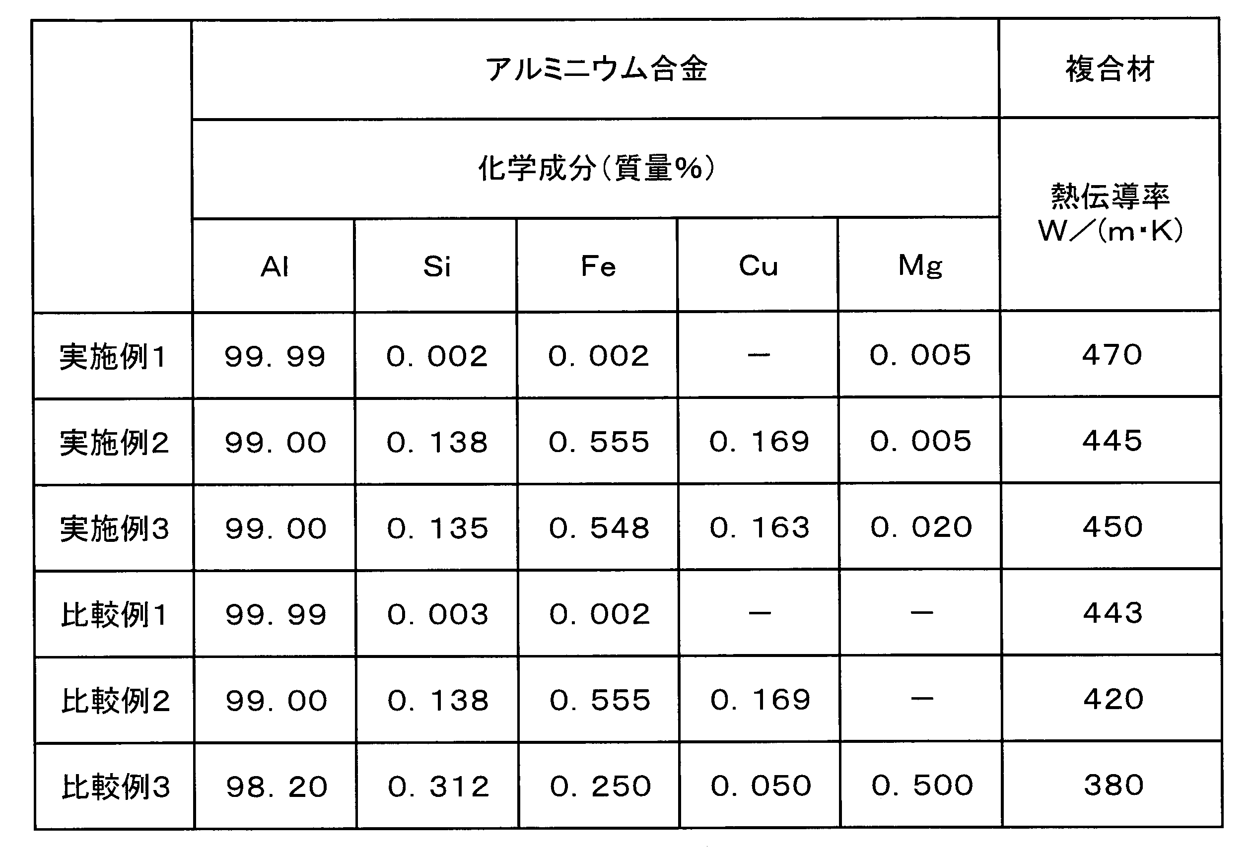
特定のアルミニウム合金の化学成分をICP発光分光分析法で定量分析した。その結果を表1中の「化学成分」欄に示した。なお、この欄中の「-」は検出限界以下(即ち0.001質量%(10質量ppm)以下)を意味している。
次いで、特定のアルミニウム合金鋳造物をアルミニウム箔の素材として用いて冷間圧延によりアルミニウム箔の条材を製造した。その後、アルミニウム箔の条材を焼鈍した。焼鈍温度は400℃であった。アルミニウム箔の条材の厚さは20μmであった。
また、炭素粒子としての鱗片状黒鉛粒子とバインダー液とを混合撹拌して塗料を調製した。鱗片状黒鉛粒子の最長軸方向の平均長さは300μm、そのアスペクト比は30であった。なお、鱗片状黒鉛粒子の最長軸方向の平均長さは次の方法により算出した。すなわち、ガラス板上に分散させた多数の鱗片状黒鉛粒子の中から任意に選択した100個の鱗片状黒鉛粒子をそれぞれ光学顕微鏡により観察し、各鱗片状黒鉛粒子の最も長い方向の長さを測定した。そして、それらの算術平均値を鱗片状黒鉛粒子の最長軸方向の平均長さとした。
バインダー液はバインダー樹脂を溶剤で溶解することにより調製したものである。バインダー樹脂としてポリエチレンオキサイドとポリビニルアルコールとの混合体を用い、溶剤として水とイソプロピルアルコールとの混合溶剤を用いた。
次いで、塗料をアルミニウム箔の条材上に3本ロールコーターにより塗工し150℃で乾燥することにより、炭素粒子塗工箔の条材としての鱗片状黒鉛粒子塗工箔の条材を得た。
この塗工箔の条材を正方形状に裁断し、その裁断片(即ち鱗片状黒鉛粒子塗工箔)を複数積層することにより、鱗片状黒鉛粒子塗工箔が複数積層された状態の積層体を第1焼結素材として形成した。
次いで、積層体を真空中にて加圧しながら加熱することにより焼結し、これによりアルミニウム-炭素子複合材としてのアルミニウム-鱗片状黒鉛粒子複合材を製造した。積層体の焼結温度は600℃であり、焼結時間は180minであり、積層体への加圧方向は積層体の厚さ方向であり、積層体への加圧力は20MPaであった。複合材の厚さは0.5mmであった。複合材における鱗片状黒鉛粒子とアルミニウムマトリックスとの体積比率は30(鱗片状黒鉛粒子):70(アルミニウムマトリックス)であった。
複合材の熱伝導率を調べるため、複合材の熱拡散率をレーザーフラッシュ法により測定し、この熱拡散率に複合材の密度及び比熱を乗じることにより、複合材の25℃での熱伝導率を算出した。その結果を表1中の「熱伝導率」欄に示した。
さらに、複合材のAl/C界面の断面TEM解析により複合材中のMgの分布状態を調べたところ、複合材中のMgはAl/C界面に濃化していた。
<実施例2>
純度99.00質量%の純アルミニウム(合金記号:A1100)の溶湯にMg粉末を所定量添加することによりMg含有量が50質量ppm(0.005質量%)の特定のアルミニウム合金を調製した。そしてこの特定のアルミニウム合金を鋳造することにより、特定のアルミニウム合金鋳造物を製造した。
純度99.00質量%の純アルミニウム(合金記号:A1100)の溶湯にMg粉末を所定量添加することによりMg含有量が50質量ppm(0.005質量%)の特定のアルミニウム合金を調製した。そしてこの特定のアルミニウム合金を鋳造することにより、特定のアルミニウム合金鋳造物を製造した。
特定のアルミニウム合金の化学成分をICP発光分光分析法で定量分析した。その結果を表1中の「化学成分」欄に示した。
この特定のアルミニウム合金鋳造物を用いて上記実施例1と同じ方法によりアルミニウム-鱗片状黒鉛粒子複合材を製造した。
複合材の熱伝導率を上記実施例1と同じ方法で算出した。その結果を表1中の「熱伝導率」欄に示した。
さらに、複合材中のMgの分布状態を上記実施例1と同じ方法により調べたところ、複合材中のMgは上記実施例1と同じように分布していた。
<実施例3>
純度99.00質量%の純アルミニウム(合金記号:A1100)の溶湯にMg粉末を所定量添加することによりMg含有量が200質量ppm(0.020質量%)の特定のアルミニウム合金を調製した。そしてこの特定のアルミニウム合金を鋳造することにより、特定のアルミニウム合金鋳造物を製造した。
純度99.00質量%の純アルミニウム(合金記号:A1100)の溶湯にMg粉末を所定量添加することによりMg含有量が200質量ppm(0.020質量%)の特定のアルミニウム合金を調製した。そしてこの特定のアルミニウム合金を鋳造することにより、特定のアルミニウム合金鋳造物を製造した。
特定のアルミニウム合金の化学成分をICP発光分光分析法で定量分析した。その結果を表1中の「化学成分」欄に示した。
この特定のアルミニウム合金鋳造物を用いて上記実施例1と同じ方法によりアルミニウム-鱗片状黒鉛粒子複合材を製造した。
複合材の熱伝導率を上記実施例1と同じ方法で算出した。その結果を表1中の「熱伝導率」欄に示した。
さらに、複合材中のMgの分布状態を上記実施例1と同じ方法により調べたところ、複合材中のMgは上記実施例1と同じように分布していた。
<比較例1>
純度99.99質量%の純アルミニウム(合金記号:A1N99)からなるアルミニウム箔の条材を準備した。その厚さは20μmであった。
純度99.99質量%の純アルミニウム(合金記号:A1N99)からなるアルミニウム箔の条材を準備した。その厚さは20μmであった。
純アルミニウムの化学成分をICP発光分光分析法で定量分析した。その結果を表1中の「化学成分」欄に示した。
このアルミニウム箔の条材を用いて上記実施例1と同じ方法によりアルミニウム-鱗片状黒鉛粒子複合材を製造した。
複合材の熱伝導率を上記実施例1と同じ方法で算出した。その結果を表1中の「熱伝導率」欄に示した。
<比較例2>
純度99.00質量%の純アルミニウム(合金記号:A1100)からなるアルミニウム箔の条材を準備した。その厚さは20μmであった。
純度99.00質量%の純アルミニウム(合金記号:A1100)からなるアルミニウム箔の条材を準備した。その厚さは20μmであった。
純アルミニウムの化学成分をICP発光分光分析法で定量分析した。その結果を表1中の「化学成分」欄に示した。
このアルミニウム箔の条材を用いて上記実施例1と同じ方法によりアルミニウム-鱗片状黒鉛粒子複合材を製造した。
複合材の熱伝導率を上記実施例1と同じ方法で算出した。その結果を表1中の「熱伝導率」欄に示した。
<比較例3>
純アルミニウムではなくアルミニウム合金(合金記号:A6063)からなるアルミニウム箔の条材を準備した。その厚さは20μmであった。
純アルミニウムではなくアルミニウム合金(合金記号:A6063)からなるアルミニウム箔の条材を準備した。その厚さは20μmであった。
アルミニウム合金の化学成分をICP発光分光分析法で定量分析した。その結果を表1中の「化学成分」欄に示した。
このアルミニウム箔の条材を用いて上記実施例1と同じ方法によりアルミニウム-鱗片状黒鉛粒子複合材を製造した。
複合材の熱伝導率を上記実施例1と同じ方法で算出した。その結果を表1中の「熱伝導率」欄に示した。
<<評価>>
表1に示すように、実施例1~3の複合材の熱伝導率及び比較例1~2の複合材の熱伝導率はいずれも比較例3の複合材の熱伝導率よりも高かった。
表1に示すように、実施例1~3の複合材の熱伝導率及び比較例1~2の複合材の熱伝導率はいずれも比較例3の複合材の熱伝導率よりも高かった。
さらに、実施例1の複合材の熱伝導率と比較例1の複合材の熱伝導率とを比較すると、前者の方が後者よりも高かった。
また、実施例2及び3の複合材の熱伝導率と比較例2の複合材の熱伝導率とを比較すると、前者の方が後者よりも高かった。
本願は、2018年11月21日付で出願された日本国特許出願の特願2018-218031号の優先権主張を伴うものであり、その開示内容は、そのまま本願の一部を構成するものである。
ここに用いられた用語及び表現は、説明のために用いられたものであって限定的に解釈するために用いられたものではなく、ここに示され且つ述べられた特徴事項の如何なる均等物をも排除するものではなく、この発明のクレームされた範囲内における各種変形をも許容するものであると認識されなければならない。
本発明は、多くの異なった形態で具現化され得るものであるが、この開示は本発明の原理の実施例を提供するものと見なされるべきであって、それら実施例は、本発明をここに記載しかつ/または図示した好ましい実施形態に限定することを意図するものではないという了解のもとで、多くの図示実施形態がここに記載されている。
本発明はアルミニウム-炭素粒子複合材及びその製造方法に利用可能である。
1:アルミニウム-炭素粒子複合材
2:アルミニウムマトリックス
3:炭素粒子
4:アルミニウムマトリックスと炭素粒子との界面(Al/C界面)
6:アルミニウム箔
7:炭素粒子塗工箔
8:アルミニウム粒子
11:第1焼結素材
12:積層体
13:第2焼結素材
14:混合体
21:アルミニウムマトリックスの領域(アルミニウムマトリックス領域)
22:炭素粒子の領域(炭素領域)
23:AlとOとの化合物層(Al-O化合物層)
24:AlとOとCとの化合物層(Al-O-C化合物層)
2:アルミニウムマトリックス
3:炭素粒子
4:アルミニウムマトリックスと炭素粒子との界面(Al/C界面)
6:アルミニウム箔
7:炭素粒子塗工箔
8:アルミニウム粒子
11:第1焼結素材
12:積層体
13:第2焼結素材
14:混合体
21:アルミニウムマトリックスの領域(アルミニウムマトリックス領域)
22:炭素粒子の領域(炭素領域)
23:AlとOとの化合物層(Al-O化合物層)
24:AlとOとCとの化合物層(Al-O-C化合物層)
Claims (10)
- アルミニウムマトリックスと、前記アルミニウムマトリックス中に分散した炭素粒子とを含み、
前記アルミニウムマトリックスのアルミニウム材料として、純度99.00質量%以上の純アルミニウムにMg含有量が20~300質量ppmの範囲になるようにMgが添加されてなるアルミニウム合金が用いられているアルミニウム-炭素粒子複合材。 - アルミニウムマトリックスと、前記アルミニウムマトリックス中に分散した炭素粒子とを含み、
純度99.00質量%以上の純アルミニウムにMg含有量が20~300質量ppmの範囲になるようにMgを添加してアルミニウム合金を調製する工程と、
前記アルミニウム合金からなるアルミニウム材料と炭素粒子とを含む焼結素材を焼結する工程とを経て得られたアルミニウム-炭素粒子複合材。 - 前記アルミニウムマトリックスと前記炭素粒子との界面に、AlとOとの化合物層が形成されており、
前記AlとOとの化合物層の厚さが20nm以下である請求項1又は2記載のアルミニウム-炭素粒子複合材。 - 前記アルミニウムマトリックスと前記炭素粒子との界面に、AlとOとCとの化合物層が形成されており、
前記AlとOとCとの化合物層の厚さが20nm以下である請求項1~3のいずれかに記載のアルミニウム-炭素粒子複合材。 - Mgは、前記アルミニウムマトリックスと前記炭素粒子との界面に濃化している請求項1~4のいずれかに記載のアルミニウム-炭素粒子複合材。
- 前記炭素粒子として、黒鉛粒子、グラフェン、炭素繊維及びカーボンナノチューブからなる群より選択される少なくとも一種が用いられている請求項1~5のいずれかに記載のアルミニウム-炭素粒子複合材。
- 冷却器又は放熱器の材料として用いられる請求項1~6のいずれかに記載のアルミニウム-炭素粒子複合材。
- 純度99.00質量%以上の純アルミニウムにMg含有量が20~300質量ppmの範囲になるようにMgを添加してアルミニウム合金を調製する工程と、
第1焼結素材を焼結する工程とを備え、
前記第1焼結素材を焼結する工程は、前記アルミニウム合金からなるアルミニウム箔を製造する工程と、炭素粒子を含有する塗料を前記アルミニウム箔上に塗工し乾燥することにより炭素粒子塗工箔を製造する工程とを含み、
前記第1焼結素材を焼結する工程では、前記炭素粒子塗工箔が複数積層された状態の積層体を前記第1焼結素材として焼結するアルミニウム-炭素粒子複合材の製造方法。 - 純度99.00質量%以上の純アルミニウムにMg含有量が20~300質量ppmの範囲になるようにMgを添加してアルミニウム合金を調製する工程と、
第2焼結素材を焼結する工程とを備え、
前記第2焼結素材を焼結する工程は、前記アルミニウム合金からなるアルミニウム粒子を製造する工程を含み、
前記第2焼結素材を焼結する工程では、前記アルミニウム粒子と炭素粒子との混合体を前記第2焼結素材として焼結するアルミニウム-炭素粒子複合材の製造方法。 - 前記炭素粒子として、黒鉛粒子、グラフェン、炭素繊維及びカーボンナノチューブからなる群より選択される少なくとも一種が用いられる請求項8又は9記載のアルミニウム-炭素粒子複合材の製造方法。
Priority Applications (2)
| Application Number | Priority Date | Filing Date | Title |
|---|---|---|---|
| CN201980064392.9A CN112823214B (zh) | 2018-11-21 | 2019-10-17 | 铝-碳粒子复合材料及其制造方法 |
| JP2020558164A JP7342881B2 (ja) | 2018-11-21 | 2019-10-17 | アルミニウム-炭素粒子複合材及びその製造方法 |
Applications Claiming Priority (2)
| Application Number | Priority Date | Filing Date | Title |
|---|---|---|---|
| JP2018-218031 | 2018-11-21 | ||
| JP2018218031 | 2018-11-21 |
Publications (1)
| Publication Number | Publication Date |
|---|---|
| WO2020105328A1 true WO2020105328A1 (ja) | 2020-05-28 |
Family
ID=70774054
Family Applications (1)
| Application Number | Title | Priority Date | Filing Date |
|---|---|---|---|
| PCT/JP2019/040872 Ceased WO2020105328A1 (ja) | 2018-11-21 | 2019-10-17 | アルミニウム-炭素粒子複合材及びその製造方法 |
Country Status (3)
| Country | Link |
|---|---|
| JP (1) | JP7342881B2 (ja) |
| CN (1) | CN112823214B (ja) |
| WO (1) | WO2020105328A1 (ja) |
Cited By (1)
| Publication number | Priority date | Publication date | Assignee | Title |
|---|---|---|---|---|
| CN113699417A (zh) * | 2021-08-30 | 2021-11-26 | 中北大学 | 一种Al2O3/Fe3O4@GNS混杂增强铝基复合材料及其制备方法 |
Families Citing this family (3)
| Publication number | Priority date | Publication date | Assignee | Title |
|---|---|---|---|---|
| CN113355548B (zh) * | 2021-05-28 | 2022-06-14 | 上海交通大学 | 一种石墨烯增强铝基复合材料的气氛控制粉末冶金制备方法 |
| CN116922877A (zh) * | 2022-04-07 | 2023-10-24 | 苏州南诣科技有限公司 | 一种石墨烯复合纵向导热薄膜及其制备方法 |
| KR20250097314A (ko) | 2023-12-21 | 2025-06-30 | 재단법인 경북하이브리드부품연구원 | 알루미늄 압출재 제조 방법 및 이에 의하여 제조된 알루미늄 압출재 |
Citations (1)
| Publication number | Priority date | Publication date | Assignee | Title |
|---|---|---|---|---|
| JP2017082309A (ja) * | 2015-10-30 | 2017-05-18 | 矢崎総業株式会社 | 締結部材 |
Family Cites Families (16)
| Publication number | Priority date | Publication date | Assignee | Title |
|---|---|---|---|---|
| US5508120A (en) * | 1994-08-12 | 1996-04-16 | The Dow Chemical Company | Boron carbide cermet structural materials with high flexure strength at elevated temperatures |
| JP4597279B2 (ja) * | 1998-07-31 | 2010-12-15 | 弘治 大石橋 | 熱良導複合材料 |
| JP2000345254A (ja) * | 1999-06-03 | 2000-12-12 | Toyota Motor Corp | アルミニウム基複合材料およびその製造方法 |
| JP4711165B2 (ja) * | 2004-06-21 | 2011-06-29 | 日立金属株式会社 | 高熱伝導・低熱膨脹複合体およびその製造方法 |
| JP4279221B2 (ja) * | 2004-09-10 | 2009-06-17 | 日信工業株式会社 | 複合金属材料及びその製造方法、キャリパボディ、ブラケット、ディスクロータ、ドラム並びにナックル |
| CN1944698A (zh) * | 2006-10-24 | 2007-04-11 | 北京科技大学 | 一种超高导热、低热膨胀系数的复合材料及其制备方法 |
| JP5229934B2 (ja) * | 2007-07-05 | 2013-07-03 | 住友精密工業株式会社 | 高熱伝導性複合材料 |
| JP5496888B2 (ja) * | 2008-07-17 | 2014-05-21 | 電気化学工業株式会社 | アルミニウム−ダイヤモンド系複合体の製造方法 |
| KR20130000647A (ko) * | 2011-06-23 | 2013-01-03 | 권한상 | 알루미늄 및 카본나노튜브를 이용한 전력용 복합 선재 제조방법 및 그것에 의해 제조된 제품 |
| CN103343265B (zh) * | 2013-07-24 | 2015-12-02 | 上海交通大学 | 石墨/硅混杂增强高导热低膨胀铝基复合材料 |
| CN104264000B (zh) * | 2014-09-03 | 2016-09-07 | 上海交通大学 | 石墨烯改性的高导热铝基复合材料及其粉末冶金制备方法 |
| CN104630570B (zh) * | 2014-12-11 | 2017-02-22 | 中车青岛四方机车车辆股份有限公司 | 一种高阻尼碳纳米管/铝合金复合材料及其制备方法 |
| WO2017110140A1 (ja) * | 2015-12-24 | 2017-06-29 | 昭和電工株式会社 | 金属と炭素繊維との複合材の製造方法 |
| JP2016180185A (ja) * | 2016-05-09 | 2016-10-13 | デンカ株式会社 | アルミニウム合金−セラミックス複合体、この複合体の製造方法、及びこの複合体からなる応力緩衝材 |
| JP6755779B2 (ja) * | 2016-11-11 | 2020-09-16 | 昭和電工株式会社 | 金属−炭素粒子複合材及びその製造方法 |
| CN106498223B (zh) * | 2016-11-16 | 2019-01-25 | 银邦金属复合材料股份有限公司 | 一种改性石墨烯增强铝基复合材料及其制备方法 |
-
2019
- 2019-10-17 CN CN201980064392.9A patent/CN112823214B/zh active Active
- 2019-10-17 JP JP2020558164A patent/JP7342881B2/ja active Active
- 2019-10-17 WO PCT/JP2019/040872 patent/WO2020105328A1/ja not_active Ceased
Patent Citations (1)
| Publication number | Priority date | Publication date | Assignee | Title |
|---|---|---|---|---|
| JP2017082309A (ja) * | 2015-10-30 | 2017-05-18 | 矢崎総業株式会社 | 締結部材 |
Cited By (2)
| Publication number | Priority date | Publication date | Assignee | Title |
|---|---|---|---|---|
| CN113699417A (zh) * | 2021-08-30 | 2021-11-26 | 中北大学 | 一种Al2O3/Fe3O4@GNS混杂增强铝基复合材料及其制备方法 |
| CN113699417B (zh) * | 2021-08-30 | 2022-03-08 | 中北大学 | 一种Al2O3/Fe3O4@GNS混杂增强铝基复合材料的制备方法 |
Also Published As
| Publication number | Publication date |
|---|---|
| CN112823214B (zh) | 2022-11-04 |
| JPWO2020105328A1 (ja) | 2021-10-07 |
| JP7342881B2 (ja) | 2023-09-12 |
| CN112823214A (zh) | 2021-05-18 |
Similar Documents
| Publication | Publication Date | Title |
|---|---|---|
| JP7342881B2 (ja) | アルミニウム-炭素粒子複合材及びその製造方法 | |
| JP4711165B2 (ja) | 高熱伝導・低熱膨脹複合体およびその製造方法 | |
| US9879925B2 (en) | Heat dissipation sheet manufactured using graphene/graphite nanoplate/carbon nanotube/nano-metal complex and method of manufacturing the same | |
| CN1894435B (zh) | 金属基碳纤维复合材料的制造方法 | |
| CN108251076B (zh) | 碳纳米管-石墨烯复合散热膜、其制备方法与应用 | |
| CN106967424B (zh) | 氮化物荧光体的制造方法、氮化物荧光体及发光装置 | |
| JP6166117B2 (ja) | 金属と炭素繊維との複合材の製造方法 | |
| TW202102432A (zh) | 塊狀氮化硼粒子、熱傳導樹脂組成物、以及散熱構件 | |
| CN105986158B (zh) | 一种高导热金刚石‑金属复合材料及其制备方法 | |
| Zhang et al. | Effects of sintering pressure on the densification and mechanical properties of nanosilver double-side sintered power module | |
| WO2018088045A1 (ja) | 金属-炭素粒子複合材及びその製造方法 | |
| CN111149442A (zh) | 使用合成石墨粉末生产导热薄膜的方法 | |
| CN102534331A (zh) | 一种高导热金刚石/铝复合材料的制备方法 | |
| CN109266914B (zh) | 一种石墨烯增强金属基复合材料的制备方法 | |
| CN104057653A (zh) | 一种石墨膜/金属复合散热片及其制备方法 | |
| Chen et al. | Reinforced heat dissipation by simple graphene coating for phosphor-in-glass applied in high-power LED | |
| KR102183485B1 (ko) | 폐흑연을 이용한 방열 시트의 제조 방법 | |
| CN111822697A (zh) | 含铝复合散热板的制造方法以及利用上述制造方法制造的含铝复合散热板 | |
| US20230022914A1 (en) | Metal Matrix Nano Carbon Material Composites Produced With Low Temperature Processing | |
| JP2019026884A (ja) | 金属−炭素粒子複合材 | |
| CN113929074B (zh) | 碳材及其应用 | |
| JP6653888B2 (ja) | AlN結晶の作製方法、及びAlN結晶の作製装置 | |
| JP2022132460A (ja) | 粒子塗工箔の製造方法及び金属-粒子複合材の製造方法 | |
| Koizumi et al. | Properties of Ce3+-doped Y3Al5O12 phosphor nanoparticles formed by laser ablation in liquid | |
| JP6383670B2 (ja) | アルミニウムと炭素粒子との複合材の製造方法及び絶縁基板の製造方法 |
Legal Events
| Date | Code | Title | Description |
|---|---|---|---|
| 121 | Ep: the epo has been informed by wipo that ep was designated in this application |
Ref document number: 19888111 Country of ref document: EP Kind code of ref document: A1 |
|
| ENP | Entry into the national phase |
Ref document number: 2020558164 Country of ref document: JP Kind code of ref document: A |
|
| NENP | Non-entry into the national phase |
Ref country code: DE |
|
| 122 | Ep: pct application non-entry in european phase |
Ref document number: 19888111 Country of ref document: EP Kind code of ref document: A1 |