WO2020105238A1 - 移動補助装置 - Google Patents
移動補助装置Info
- Publication number
- WO2020105238A1 WO2020105238A1 PCT/JP2019/032808 JP2019032808W WO2020105238A1 WO 2020105238 A1 WO2020105238 A1 WO 2020105238A1 JP 2019032808 W JP2019032808 W JP 2019032808W WO 2020105238 A1 WO2020105238 A1 WO 2020105238A1
- Authority
- WO
- WIPO (PCT)
- Prior art keywords
- handrail
- assisting device
- contact
- contact body
- movement assisting
- Prior art date
- Legal status (The legal status is an assumption and is not a legal conclusion. Google has not performed a legal analysis and makes no representation as to the accuracy of the status listed.)
- Ceased
Links
Images



Classifications
-
- A—HUMAN NECESSITIES
- A61—MEDICAL OR VETERINARY SCIENCE; HYGIENE
- A61H—PHYSICAL THERAPY APPARATUS, e.g. DEVICES FOR LOCATING OR STIMULATING REFLEX POINTS IN THE BODY; ARTIFICIAL RESPIRATION; MASSAGE; BATHING DEVICES FOR SPECIAL THERAPEUTIC OR HYGIENIC PURPOSES OR SPECIFIC PARTS OF THE BODY
- A61H3/00—Appliances for aiding patients or disabled persons to walk about
-
- E—FIXED CONSTRUCTIONS
- E04—BUILDING
- E04F—FINISHING WORK ON BUILDINGS, e.g. STAIRS, FLOORS
- E04F11/00—Stairways, ramps, or like structures; Balustrades; Handrails
- E04F11/18—Balustrades; Handrails
Definitions
- the present invention relates to a movement assisting device that includes a gripping portion that is gripped by a user or that holds luggage and that moves along a handrail to assist the movement of the user.
- a rod-shaped rail is provided on the side wall of a stair along the slope of the stair, and the main body is moved along the rail to assist the walking of a user who holds the grip extending from the main.
- Mobility aids are known.
- a plurality of rollers axially supported by the main body so as to be rotatable in the axial direction of the rail are provided on the circumferential surface of the rail in the circumferential direction. It is known that the rails are held in contact with each other at equal intervals and the rails are held by those rollers (for example, refer to Patent Document 1).
- the movement assisting device described in Patent Document 1 can also be used as a handrail for a user to grip a rail for guiding the movement assisting device.
- the rail can be gripped by a user as a handrail, the rail has a diameter and a cross-sectional shape that are premised on being held by the movement assisting device. Etc. are set.
- handrails are not based on the assumption that they are held by the movement assisting device, and therefore various handrails can be used depending on the shape of the stairs on which the handrail is installed, the type of building to be installed, and the like. It has various diameters and cross-sectional shapes.
- some existing handrails have a different diameter.
- the diameter of the bent portion becomes large at that portion.
- the present invention has been made in view of the above points, and an object thereof is to provide a movement assisting device that can be applied to various existing handrails.
- the movement assisting device of the present invention is A movement assisting device that includes a main body portion that holds a handrail and a grip portion that extends from the main body portion, and that moves along the handrail to assist the movement of the user.
- a first unit that is supported by the main body and that holds the handrail by abutting the handrail at positions displaced from each other in the circumferential direction of the handrail and that is movable in the axial direction of the handrail on the surface of the handrail.
- a contact body, a second contact body, and a third contact body A drive mechanism that transmits a driving force to the first contact body to move the first contact body, At least one contact body of the first contact body, the second contact body, and the third contact body is separable from the handrail, It is characterized in that the main body portion has a biasing mechanism that biases the contact body, which comes into contact with the handrail so as to be separable, toward the handrail side.
- the“ contact body ” refers to a body that can move in the axial direction of the handrail on the surface of the handrail while being in contact with the surface of the handrail.
- Specific examples thereof include rolling elements such as rollers and endless tracks, and those capable of sliding on the surface of a handrail such as a Teflon (registered trademark) processed ball.
- the handrail is held by at least three contact bodies, and one of the contact bodies is configured to contact the handrail so as to be separable. That is, the space for holding the handrail can be changed.
- this movement assisting device as compared with the conventional movement assisting device in which the space for holding the handrail is defined to have a predetermined size, various thicknesses of various diameters and cross-sectional shapes can be obtained.
- the handrail can be held.
- the abutment body that comes into contact with the handrail in a separable manner is urged toward the handrail by an urging mechanism. As a result, even if the contact body is moved while holding the handrail, the holding force of the contact body is maintained regardless of the diameter of the handrail.
- this movement assisting device maintains the size of its diameter while holding the handrail.
- the changing part can be moved.
- the movement assisting device of the present invention it is possible to hold handrails having various diameter sizes, cross-sectional shapes, and the like, and the diameter size changes while the handrails are held. Since the part can also be moved, it can be applied to a wide variety of existing handrails.
- the first contact body contacts the handrail from above the handrail
- the second contact body is separable from the handrail on one side in the horizontal direction of the handrail
- the third contact body is separable from the handrail on the other side in the horizontal direction of the handrail
- the main body portion includes a first biasing mechanism that biases the second contact body toward the handrail side, and a second biasing mechanism that biases the third contact body toward the handrail side. And a mechanism.
- the state in which the driven first contact body is placed above the central axis of the handrail can be stably maintained. That is, the driven first contact body can be stably brought into contact with above the central axis of the handrail. Consequently, the force for the movement assisting device to move in the axial direction of the handrail (that is, the force for assisting the movement of the user) can be made stable.
- the biasing mechanism applies a constant load to the abutting body regardless of the position of the abutting body that comes into contact with the handrail in a freely separable manner.
- the force with which the contact body holds the handrail or the force with which the contact body moves on the surface of the handrail along the central axis is due to the biasing force of the biasing member that biases the contact body toward the handrail. Increase or decrease. Therefore, if the biasing member is configured to apply a constant load to the contact body in this way, a stable holding force or driving force can be obtained. Consequently, the force for the movement assisting device to move in the axial direction of the handrail (that is, the force for assisting the movement of the user) can be made stable.
- the biasing mechanism in the case where the biasing mechanism applies a constant load to the contact body, is preferably configured by using a constant force spring.
- the urging mechanism for applying such a stable load in addition to the one using an elastic body such as the spring as described above, there is one including an actuator and a control unit for controlling it. Can be mentioned.
- the first abutment body abuts the handrail from above the handrail above the central axis of the handrail
- the second contact body is in contact with the handrail laterally of the center axis from one side of the handrail in the horizontal direction
- the third contact body comes into contact with the handrail from the other side in the horizontal direction of the handrail below a contact position between the handrail and the second contact body.
- At least one of the second contact body and the third contact body is preferably separable from the handrail.
- existing handrails have struts extending downward or sideways from the handrail.
- the handrail is firmly gripped and the third abutment is provided on the other side in the horizontal direction of the handrail.
- a wide space can be secured between the first contact body and the third contact body, and on the lower side of the handrail, below the second contact body, A wide space can be secured between the second contact body and the third contact body.
- the movement assisting device can be applied to the existing handrail, and when the movement assisting device moves along the handrail, it is possible to easily avoid the pillar extending from the existing handrail through the gap between them. You can
- auxiliary arm extending downward from the main body.
- the movement assisting device of the present invention holds the handrail by the contact body, so that the force in the normal use range (specifically, for example, the force applied when assisting the movement of the user, the normal load hanging). It is possible to sufficiently suppress unintentional rotation around the central axis of the handrail even if a force applied when the handrail is applied).
- the auxiliary arm when the auxiliary arm is extended downward from the main body in this way, even if the movement assisting device is unintentionally rotated, the auxiliary arm is provided on the side wall or the like where the handrail is provided. It is possible to abut and suppress further rotation. As a result, it is possible to prevent the user from falling further and dropping the hung luggage.
- the auxiliary arm in the case of a configuration including an auxiliary arm, it is preferable that the auxiliary arm has an auxiliary rolling element that can roll along the axial direction of the handrail.
- the movement of the movement assist device may be hindered by the friction between the side wall and the auxiliary arm, depending on the surface shape of the side wall where the handrail is provided. Therefore, with this configuration, the friction can be reduced, and thus the movement of the movement assisting device is less likely to be hindered by the friction.
- the movement assisting device of the present invention It is provided with a tubular main body portion for holding the handrail so that the handrail is inserted, and a grip portion extending from the main body portion, and moves along the handrail to allow the user to move through the grip portion.
- a movement assisting device for assisting movement A first abutment body, a second abutment body, and a third abutment body, which are supported on the inner peripheral side of the body portion and are located at positions displaced from each other in the circumferential direction;
- a drive mechanism that transmits a driving force to the first contact body and moves the first contact body in the axial direction of the main body, At least one contact body of the first contact body, the second contact body, and the third contact body is movable in a direction approaching or separating from the axis of the main body portion,
- the main body is characterized by having an urging mechanism for urging the contact body movable with respect to the axis toward the axis.
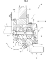
- FIG. 3 is a sectional view taken along the line AA of the movement assisting device of FIG. 2.
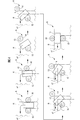
- FIG. 3 is a plan view showing a trajectory and a state when the roller of the movement assisting device of FIG.
- the front view which shows the 1st modification of the movement assistance apparatus of FIG.
- the front view which shows the 2nd modification of the movement assistance apparatus of FIG.
- the movement assisting device A is installed on the handrail R provided on the side walls of the stairs S and the corridor C.
- the movement assisting device A guides the user U who holds the grip portion 2 (see FIG. 2) of the movement assisting device A by moving along the handrail R to move the user U himself (specifically, To assist in climbing stairs S and walking in corridor C). It is also possible to hang a luggage on the grip portion 2. Accordingly, the movement assisting device A can assist the movement of the user U by carrying the luggage instead of the user U.
- the movement assisting device A includes a main body 1 that holds the handrail R and a grip that extends laterally from the main body 1 and is gripped by a user U or that luggage is fixed. And part 2.
- the main body 1 is formed in a tubular shape, and holds the handrail R by inserting the handrail R into the inside thereof.
- the “cylindrical” may have a shape in which a part thereof is open when viewed in the axial direction.
- the main body 1 is provided with a casing 10, a first link mechanism 11 slidably provided in the casing 10 in a horizontal direction, and a rotatably provided in the casing 10.
- a second link mechanism 12 a drive wheel 13 (first abutment body) rotatably supported by the housing 10, and a first support wheel 14 rotatably supported by the first link mechanism 11 ( A second contact body) and a second support wheel 15 (third contact body) rotatably supported by the second link mechanism 12.
- each of the drive wheel 13, the first support wheel 14, and the second support wheel 15 is on the inner peripheral side of the main body 1 in the circumferential direction of the rod-shaped part r1 of the handrail R (that is, the main body part).
- the handrail R is held by contacting the handrail R at a position displaced in the circumferential direction 1).
- the main body 1 includes an actuator 16 (driving source) mounted on the housing 10, a pair of first springs 17 (first urging mechanism) that applies an urging force to the first link mechanism 11,
- the two-link mechanism 12 is provided with a pair of second springs 18 (second urging mechanism) for applying an urging force.
- the drive wheel 13 is a rubber roller rotatably supported inside the housing 10.
- the drive wheel 13 is on the upper surface of the rod-shaped portion r1 of the handrail R from above and above the first axis a1 that is the central axis of the handrail R. Abutting position.
- the driving force is transmitted to the drive wheel 13 via the actuator 16 and a gear (not shown) provided inside the housing 10. According to the driving force, the drive wheel 13 rolls forward or backward on the surface of the rod-shaped portion r1 of the handrail R in the direction of the axis a1 of the handrail R.
- a suspension (not shown) is provided between the drive wheel 13 and the housing 10, and the movement of the drive wheel 13 in the vertical direction can be permitted to some extent.
- the first support wheel 14 is a rubber roller rotatably supported by the tip of the first link mechanism 11.
- the first support wheel 14 is a surface on one side of the bar-shaped portion r1 of the handrail R from one side in the horizontal direction (right side in FIG. 3) when the movement assisting device A is attached to the handrail R. It comes into contact with a position on the side of the one axis a1.
- the first support wheel 14 can roll on the surface of the rod-shaped portion r1 of the handrail R along the first axis a1 as the drive wheel 13 moves.
- the first link mechanism 11 is a plane that extends in the horizontal direction (specifically, includes the first axis line a1 that is the central axis line of the handrail R and expands in the vertical direction). It is configured to be slidable in a direction orthogonal to.
- the tip end portion of the first link mechanism 11 and the first support wheel 14 supported by the tip end portion can be separated from the peripheral surface of the rod-shaped portion r1 of the handrail R on the one side in the horizontal direction. Is becoming That is, it is movable in a direction toward or away from the axis of the main body 1.
- the rod-shaped portion r1 of the handrail R is provided from the first spring 17 to the tip portion of the first link mechanism 11 and the first support wheel 14 supported by the tip portion.
- a biasing force is applied to the side (that is, the axis side of the main body 1).
- the second support wheel 15 is a rubber roller rotatably supported by the tip of the second link mechanism 12.
- the second support wheel 15 is a surface on the other side of the rod portion r1 of the handrail R from the other side in the horizontal direction (left side in FIG. 3).
- the R and the first support wheels 14 are in contact with each other at a position lower than the contact position.
- the second support wheel 15 is allowed to roll on the surface of the rod-shaped portion r1 of the handrail R along the first axis a1 as the drive wheel 13 moves.
- the second link mechanism 12 is parallel to the first axis line a1 that is the central axis line of the handrail R and is upward and horizontal with respect to the first axis line a1. It is configured to be rotatable around a second axis a2 that is an axis located on the other side in the direction.
- the tip end portion of the second link mechanism 12 and the second support wheel 15 supported by the tip end portion can be separated from the peripheral surface of the rod-shaped portion r1 of the handrail R on the other side in the horizontal direction. Is becoming That is, it is movable in a direction toward or away from the axis of the main body 1.
- the rod-shaped portion r1 of the handrail R is formed by the second spring 18, the tip of the second link mechanism 12, and the second support wheel 15 supported by the tip.
- a biasing force is applied to the side (that is, the axis side of the main body 1).
- the first support wheel 14 and the second support wheel 15 of the drive wheel 13, the first support wheel 14, and the second support wheel 15 that hold the handrail R are The handrail R is configured to come into contact with the handrail R so as to be freely separated. That is, the space for holding the handrail R can be changed.
- this movement assisting device A as compared with the conventional movement assisting device in which the space for holding the handrail is defined to have a predetermined size, various thicknesses and cross-sectional shapes of various diameters can be obtained. Can hold the handrail.
- existing handrails have struts extending downward or sideways from the rod-shaped part.
- the handrail R in the present embodiment also includes a support portion r2 extending from below the rod-shaped portion r1 to the side wall. Then, in order to apply the movement assisting device A to an existing handrail, it is necessary to firmly hold the handrail and avoid the column (support portion r2) when moving along the handrail.
- the drive wheel 13 is brought into contact with the upper side of the first axis a1 of the handrail R from the upper side, and the first support wheel 14 is moved from the one side in the horizontal direction to the first axis line of the handrail R. a2 to the side, and the second support wheel 15 from the other side in the horizontal direction and from below to a position lower than the contact position between the handrail R and the first support wheel 14.
- the movement assisting device A firmly grips the handrail, and on the other side in the horizontal direction of the handrail R, above the second support wheel 15 and between the drive wheel 13 and the second support wheel 15.
- a wide space can be secured, and a wide space is secured between the first support wheel 14 and the second support wheel 15 on the lower side of the handrail below the first support wheel 14. ..
- the movement assisting device A is applied to an existing handrail, and when the movement assisting device A moves along the handrail, it is possible to easily avoid the support column extending from the existing handrail through the gap between them. You can do it.
- the support portion r2 of the handrail R is avoided via the space between the first support wheel 14 and the second support wheel 15.
- the driving force from the actuator 16 that is the driving mechanism causes the driving force to be transmitted only to the driving wheel 13 that is the first contact body to roll the second auxiliary contact device.
- the first support wheel 14, which is a body, and the second support wheel 15, which is a third contact body, are configured to roll as the drive wheel 13 rolls.
- the drive mechanism in the present invention is not limited to such a configuration, and the drive force is transmitted to the contact bodies other than the first contact body, which is the drive wheel, to rotate the contact body. It may be configured to move. Specifically, with the movement assisting device A in the present embodiment, in addition to the drive wheel 13 that is the first contact body, the first support wheel 14 that is the second contact body, and the third contact wheel The driving force may be transmitted to at least one of the second support wheels 15 that are the body to roll.
- the first support wheel 14 that is the second contact body is configured to be slidable with respect to the housing 10 via the first link mechanism 11, and By making the second support wheel 15 that is the three contact bodies rotatable with respect to the housing 10 via the second link mechanism 12, the contact bodies can be separated from the handrail R. Is configured.
- the structure for supporting the abutting body is not limited to such a configuration, and may be any structure for supporting the abutting body so that it can be separated from the handrail.
- the first support wheel 14 may be configured to be rotatable and the second support wheel 15 may be configured to be slidable in the horizontal direction. Further, both the first support wheel 14 and the second support wheel 15 may be configured to be rotatable or slidable. Further, at least one of the first support wheel 14 and the second support wheel 15 may be configured to be rotatable and slidable.
- the drive wheel 13 rolls along the first axis line a1 of the handrail R, as shown in the upper left diagram in FIG. .. Further, the first support wheel 14 and the second support wheel 15 move along the first axis a1 as the drive wheel 13 rolls.
- the driving wheel 13 continues to move forward due to the driving force transmitted from the actuator 16.
- the drive wheel 13 starts to rotate about a point located at a position farther from the drive wheel 13 than the second support wheel 15 (lower left side of the second support wheel 15 in FIG. 4).
- the first support wheel 14 also starts to rotate with the rotation of the drive wheel 13 about the point that is the center of rotation of the drive wheel 13.
- the handrail R sandwiched by the movement assisting device A is shown.
- the width gradually increases.
- the distance between the first support wheel 14 and the second support wheel 15 also gradually increases. More specifically, the distance between the drive wheel 13 and the first support wheel 14 and the distance between the drive wheel 13 and the second support wheel 15 also gradually increase.
- the first support wheel 14 is configured to be slidable in the horizontal direction with respect to the housing 10 by the first link mechanism 11 (see FIG. 3), and the second support wheel 14 is provided.
- the second link mechanism 12 (see FIG. 3) 15 is configured to be rotatable with respect to the housing 10. That is, the first support wheel 14 and the second support wheel 15 are independent of each other, and the distance between the first support wheel 14 and the second support wheel 15 and the drive wheel 13 pivotally supported by the housing 10 is variable.
- the distance between the drive wheel 13 and the first support wheel 14 does not increase so rapidly depending on the shape of the handrail R, while the drive wheel 13 and the second support wheel 15 are not widened.
- the drive wheel 13 moves without deviating largely from the first axis a1 of the handrail R even during this rotation.
- a biasing force is applied to the first support wheel 14 by the first spring 17 via the first link mechanism 11 so as to approach the handrail R.
- the second support wheel 15 is biased by the second spring 18 via the second link mechanism 12 so as to approach the handrail R.
- the drive wheel 13 continues to rotate around a point located farther from the drive wheel 13 than the second support wheel 15 (lower left side of the second support wheel 15 in FIG. 4).
- the first support wheel 14 also moves along with the rotation of the drive wheel 13, and continues to rotate around a point that is the center of rotation of the drive wheel 13.
- the width of the handrail R sandwiched by the movement assisting device A is gradually reduced, as shown in the upper rightmost drawing, the lower left drawing, the central drawing, and the right drawing in FIG. I will do it.
- the distance between the first support wheel 14 and the second support wheel 15 also gradually narrows. More specifically, the distance between the drive wheel 13 and the first support wheel 14 and the distance between the drive wheel 13 and the second support wheel 15 also gradually decrease.
- the first support wheel 14 is configured to be rotatable with respect to the housing 10 by the first link mechanism 11 (see FIG. 3).
- the support wheel 15 is configured to be rotatable with respect to the housing 10 by the second link mechanism 12 (see FIG. 3). That is, the first support wheel 14 and the second support wheel 15 are independent of each other, and the distance between the first support wheel 14 and the second support wheel 15 and the drive wheel 13 pivotally supported by the housing 10 is variable.
- the distance between the drive wheel 13 and the first support wheel 14 does not sharply decrease in accordance with the shape of the handrail R, while the drive wheel 13 and the second support wheel 14 do not.
- the distance from 15 will decrease rapidly.
- the drive wheel 13 moves without deviating largely from the first axis a1 of the handrail R even during this rotation.
- the first support wheel 14 is biased by the first spring 17 via the first link mechanism 11 so as to approach the handrail R.
- the second support wheel 15 is biased by the second spring 18 via the second link mechanism 12 so as to approach the handrail R.
- the movement assisting device A even if the drive wheel 13, the first support wheel 14, and the second support wheel 15 are moved while the handrail R is held, even if the drive wheel 13, the first support wheel 14, and the second support wheel 15 are linear portions. Even in the bent portion (that is, regardless of the diameter of the handrail R), the holding force is maintained.
- the handrail R is bent to the left.
- the drive wheel 13 is larger than the first axis a1 of the handrail R regardless of whether the linear portion of the handrail R is moved or the bent portion is moved. They are moving without leaving.
- biasing force of the first spring 17 that applies a biasing force to the first support wheel 14 is set to be smaller than the biasing force of the second spring 18 that applies a biasing force to the second support wheel 15. This is because the first support wheels 14 are made easier to move than the second support wheels 15 when moving the bent portion.
- the state in which the drive wheel 13 is placed above the first axis a1 of the handrail R can be stably maintained. That is, the drive wheel 13 can be stably brought into contact with the upper side of the first axis a1 of the handrail R.
- the force for moving the handrail R in the first axis a1 direction (that is, the force for assisting the movement of the user U) can be made stable. ing.
- the urging forces of the first urging member and the second urging member are not limited to such a configuration.
- a first biasing force is applied to the second support wheel 15 in the movement assisting device A of the present embodiment.
- the biasing force of the two springs may be set smaller than the biasing force of the first spring that applies the biasing force to the first support wheel 14.
- the first biasing member and the second biasing member may have the same degree.
- a rubber roller that can roll along the first axis a1 of the handrail R is used as the contact body. This is because such a roller hinders the movement in the circumferential direction, so that the entire movement assisting device A can be prevented from rotating around the first axis a1. Further, the reason why rubber is used as the material is to prevent damage to the surface of the handrail R.
- the abutment body in the present invention is not limited to such a configuration, and may be any one that can move on the surface of the handrail in the axial direction of the handrail while being in contact with the surface of the handrail. ..
- a rolling element different from a roller such as an endless track or the like, a Teflon (registered trademark) processed sphere, or the like may be used.
- both the first support wheel 14 that is the second contact body and the second support wheel 15 that is the third contact body are configured to be separable from the handrail R.
- the movement assisting device of the present invention is not limited to such a configuration, and only one of the second contact body and the third contact body may be separable from the handrail. ..
- the handrail R is supported by using the three contact bodies of the drive wheel 13, the first support wheel 14, and the second support wheel 15.
- the movement assisting device of the present invention is not limited to such a configuration and may have at least three contact bodies. For example, four or more contact bodies may be provided.
- the drive wheel 13 is brought into contact with the upper side of the first axis a1 of the handrail R from the upper side, and the first support wheel 14 is moved from the one side in the horizontal direction to the handrail R.
- the second support wheel 15 is brought into contact with the side of the first axis a1 of the above, and the second support wheel 15 is positioned on the other side in the horizontal direction and below from the contact position between the handrail R and the first support wheel 14. Abutting.
- the movement assisting device of the present invention is not limited to such a configuration, and the abutting body may be arranged in any manner as long as it can hold the handrail.
- the three contact bodies may be arranged at equal intervals.
- the peripheral surface of the roller that constitutes the rolling element 13 that is the contact body is a flat surface. This is because depending on the diameter of the handrail to be attached, smooth movement is hindered unless the drive wheel 13 moves horizontally on the upper surface of the handrail when passing through the bent portion of the handrail. This is because there is a risk that it will end up.
- the movement assisting device of the present invention is not limited to such a configuration, and the shape of the peripheral surface (contact portion) of the contact body may be appropriately designed.
- the shape of the contact portion of the contact body may be set in accordance with the shape of the peripheral surface of the handrail.
- the force of R that moves along the first axis a1 increases or decreases due to the urging forces of the first spring 17 and the second spring 18 that urge the first support wheel 14 and the second support wheel 15 toward the handrail R. ..
- a constant load can be applied to the first support wheel 14 and the second support wheel 15 regardless of the positions of the first support wheel 14 and the second support wheel 15.
- Constant load springs are used as the first spring 17 and the second spring 18.
- the holding force and the driving force are stabilized. Consequently, the force for the movement assisting device A to move in the direction of the first axis a1 of the handrail R (that is, the force for assisting the movement of the user U) is stabilized.
- the movement assisting device A uses a constant force spring as a biasing mechanism because it can apply a constant load stably even though it has a simple structure.
- stable application of a constant load that is, stabilization of the holding force and the driving force
- any urging mechanism capable of applying a constant load to the first support wheel 14 and the second support wheel 15 can be realized.
- an urging mechanism is configured by an actuator and a control device for controlling the driving force of the actuator, and the driving force is controlled so that the load based on the driving force of the actuator becomes constant. You may do so.
- the urging mechanism in the present invention is not limited to such a configuration, and any urging mechanism may be used as long as it urges an abutting body that comes into contact with the handrail in a separable manner toward the handrail side. Therefore, it is not always necessary to apply a constant load to the abutting body regardless of the position of the abutting body that comes into contact with the handrail in a freely separable manner, and the load may vary depending on the position of the abutting body. It may be.
- the movement assisting device A holds the handrail R by the drive wheel 13, the first support wheel 14, and the second support wheel 15, so that the force in a normal use range (specifically, for example, a user Even if a force applied to assist the movement of U, a force applied when a normal load is hung, or the like) is unintentionally rotated around the first axis a1 of the handrail R, It has been suppressed sufficiently.
- an auxiliary arm 3 extending downward from the main body 1 may be provided.
- the handrail R is composed of a first handrail R1 located above and a second handrail R2 located below, and the movement assisting device is attached to the first handrail R1.
- the auxiliary arm 3 comes into contact with the second handrail R2.
- the auxiliary roller 3a (auxiliary roll 3a) that can roll along the direction of the first axis a1 of the handrail R is provided. It is preferable to provide a moving body. With this configuration, the friction between the auxiliary arm 3 and the side wall W can be reduced, and thus the movement of the movement assisting device A is less likely to be hindered by the friction.
- the auxiliary arm in the present invention may be any one that can suppress the rotation of the movement assisting device. Therefore, it does not necessarily have to be extended downward in the vertical direction, and may be extended downward and obliquely toward the side wall side, or may be bent in the middle. Further, when the surface shape of the abutting handrail, the side wall, etc. is gentle, or the material of the auxiliary arm is smooth, and the friction between the handrail, the side wall and the auxiliary arm is sufficiently small, etc., The auxiliary rolling element may be omitted.
- the roller is used as the contact body, but the contact body of the present invention is not limited to such a configuration, and the handrail is in contact with the surface of the handrail. Anything can be used as long as it can move in the axial direction of the handrail on the surface of the.
- a rolling element different from a roller such as an endless track or the like, a Teflon (registered trademark) processed sphere, or the like may be used.
Landscapes
- Health & Medical Sciences (AREA)
- Architecture (AREA)
- Engineering & Computer Science (AREA)
- Rehabilitation Therapy (AREA)
- Structural Engineering (AREA)
- Epidemiology (AREA)
- Pain & Pain Management (AREA)
- Physical Education & Sports Medicine (AREA)
- Civil Engineering (AREA)
- Life Sciences & Earth Sciences (AREA)
- Animal Behavior & Ethology (AREA)
- General Health & Medical Sciences (AREA)
- Public Health (AREA)
- Veterinary Medicine (AREA)
- Rehabilitation Tools (AREA)
- Steps, Ramps, And Handrails (AREA)
Abstract
移動補助装置Aは、各々が互いに周方向にずれた位置で当接して手摺Rを保持するとともに、手摺Rの第1軸線a1方向に移動自在な駆動輪13、第1支持輪14及び第2支持輪15と、駆動輪13に駆動力を伝達するアクチュエータ16とを備える。第2支持輪15は、手摺Rに離間自在である。本体部1は、第2支持輪15を、手摺R側に向かって付勢する第2バネ18を有する。
Description
本発明は、使用者に把持される、又は、荷物が固定される把持部を備え、手摺に沿って移動して、使用者の移動を補助する移動補助装置に関する。
従来、階段の側壁にその階段の傾斜に沿って棒状のレールを設け、そのレールに沿って本体部を移動させて、本体部から延設された把持部を把持する使用者の歩行を補助する移動補助装置が知られている。
この種の移動補助装置において、本体部がレールを保持する構造としては、レールの軸線方向に回転自在となるように本体部に軸支された複数のローラを、レールの周面上で周方向に等間隔に当接させて、それらのローラによって、レールを保持するものが知られている(例えば、特許文献1参照)。
特許文献1に記載の移動補助装置は、移動補助装置を案内するためのレールを、使用者が把持するための手摺としても利用することができるようになっている。
特許文献1に記載の移動補助装置においては、そのレールは、使用者が手摺として把持することができるものではあるものの、移動補助装置で保持することを前提として、その径の太さ、断面形状等が設定されている。
これに対し、既存の手摺は、移動補助装置で保持することを前提としたものではないので、その手摺の設置されている階段の形状、設置される建築物の種類等に応じて、種々様々な径の太さ、断面形状等を備えている。
そのため、既存の手摺に対して特許文献1に記載の移動補助装置を適用しようとした場合、その手摺の径の大きさ、断面形状等によっては、移動補助装置によって手摺を保持することができないという問題があった。
また、既存の手摺は、径の大きさが変化しているものがある。例えば、手摺が途中で折れ曲がっているようなもの(特に、屈曲するように折れ曲がったもの)であった場合には、その折れ曲がった部分では、その部分で径が大きくなる。
しかし、特許文献1に記載の移動補助装置は、そのように手摺(すなわち、保持するレール)の径が変化するものを想定して構成されたものではないので、そのように径の大きさが変化する部分を移動することができない。
そのため、特許文献1の移動補助装置は、折り曲がっている等の理由によって径の大きさが変化するような手摺には、適用することができないという問題があった。
本発明は以上の点に鑑みてなされたものであり、種々様々な既存の手摺に適用することができる移動補助装置を提供することを目的とする。
本発明の移動補助装置は、
手摺を保持する本体部と、前記本体部から延設された把持部とを備え、前記手摺に沿って移動して使用者の移動を補助する移動補助装置であって、
前記本体部に支持され、各々が互いに前記手摺の周方向にずれた位置で前記手摺に当接して前記手摺を保持するとともに、前記手摺の表面上で前記手摺の軸線方向に移動自在な第1当接体、第2当接体及び第3当接体と、
前記第1当接体に駆動力を伝達し、前記第1当接体を移動させる駆動機構とを備え、
前記第1当接体、前記第2当接体及び前記第3当接体の少なくとも1つの当接体は、前記手摺に離間自在であり、
前記本体部は、前記手摺に離間自在に当接する前記当接体を、前記手摺側に向かって付勢する付勢機構を有していることを特徴とする。
手摺を保持する本体部と、前記本体部から延設された把持部とを備え、前記手摺に沿って移動して使用者の移動を補助する移動補助装置であって、
前記本体部に支持され、各々が互いに前記手摺の周方向にずれた位置で前記手摺に当接して前記手摺を保持するとともに、前記手摺の表面上で前記手摺の軸線方向に移動自在な第1当接体、第2当接体及び第3当接体と、
前記第1当接体に駆動力を伝達し、前記第1当接体を移動させる駆動機構とを備え、
前記第1当接体、前記第2当接体及び前記第3当接体の少なくとも1つの当接体は、前記手摺に離間自在であり、
前記本体部は、前記手摺に離間自在に当接する前記当接体を、前記手摺側に向かって付勢する付勢機構を有していることを特徴とする。
ここで、「当接体」とは、手摺の表面に当接した状態で、手摺の表面上を手摺の軸線方向に移動可能なものを指す。具体的には、例えば、ローラ、無限軌道等の転動体の他、テフロン(登録商標)加工された球といった手摺の表面上を摺動可能なもの等が挙げられる。
このように、本発明の移動補助装置では、少なくとも3つの当接体で手摺を保持するとともに、それらの当接体のうちの1つが、手摺に離間自在に当接するように構成されている。すなわち、手摺を保持するための空間が変動可能となっている。これにより、この移動補助装置では、従来の移動補助装置のように、手摺を保持するための空間が所定の大きさに規定されているものに比べ、種々様々な径の太さ、断面形状の手摺を保持することができる。
また、手摺に離間自在に当接する当接体は、付勢機構によって手摺側に向かって付勢されている。これにより、手摺を保持した状態で当接体が移動させられたとしても、手摺の径の大きさによらず、当接体による保持力が維持される。
その結果、この移動補助装置は、屈曲するように折れ曲がっている等の理由によって、径の大きさが変化するような手摺あっても、その手摺を保持した状態のまま、その径の大きさが変化する部分を移動することができる。
したがって、本発明の移動補助装置によれば、種々様々な径の大きさ、断面形状等を有する手摺を保持することができ、また、手摺を保持した状態のまま、径の大きさが変化する部分も移動することができるので、種々様々な既存の手摺に適用することができる。
また、本発明の移動所装置においては、
前記第1当接体は、前記手摺の上方側から、前記手摺に当接し、
前記第2当接体は、前記手摺の水平方向一方側で、前記手摺に離間自在であり、
前記第3当接体は、前記手摺の水平方向他方側で、前記手摺に離間自在であり、
前記本体部は、前記第2当接体を前記手摺側に向かって付勢する第1の付勢機構と、前記第3当接体を前記手摺側に向かって付勢する第2の付勢機構とを有していることが好ましい。
前記第1当接体は、前記手摺の上方側から、前記手摺に当接し、
前記第2当接体は、前記手摺の水平方向一方側で、前記手摺に離間自在であり、
前記第3当接体は、前記手摺の水平方向他方側で、前記手摺に離間自在であり、
前記本体部は、前記第2当接体を前記手摺側に向かって付勢する第1の付勢機構と、前記第3当接体を前記手摺側に向かって付勢する第2の付勢機構とを有していることが好ましい。
このように構成すると、駆動する当接体を手摺の上方に載置した状態で、下方に位置する2つの当接体が、その手摺を左右から挟み込む状態となる。これにより、手摺の径の大きさが変動した場合であっても、その変動による影響は、下方に位置する第2当接体及び第3当接体の移動によって吸収されて、上方に位置する第1当接体は、水平方向には移動しない。
その結果、駆動する第1当接体を手摺の中心軸線の上方に載置した状態を、安定して維持することができる。すなわち、駆動する第1当接体を手摺の中心軸線の上方に対して安定して当接させることができる。ひいては、移動補助装置が手摺の軸線方向に移動するための力(すなわち、使用者の移動を補助するための力)を安定したものとすることができる。
また、本発明の移動所装置においては、
前記付勢機構は、前記手摺に離間自在に当接する前記当接体の位置によらず、前記当接体に対して一定の荷重を加えることが好ましい。
前記付勢機構は、前記手摺に離間自在に当接する前記当接体の位置によらず、前記当接体に対して一定の荷重を加えることが好ましい。
当接体が手摺を保持する力、又は、当接体が手摺の表面上を中心軸線に沿って移動する力は、その当接体を手摺に向かって付勢する付勢部材の付勢力によって増減する。そこで、このように、当接体に対して付勢部材が一定の荷重を加えるように構成すると、安定した保持力又は駆動力を得ることができる。ひいては、移動補助装置が手摺の軸線方向に移動するための力(すなわち、使用者の移動を補助するための力)を安定したものとすることができる。
また、本発明の移動所装置においては、当接体に対して付勢機構が一定の荷重を加える構成の場合、
前記付勢機構は、定荷重バネを用いて構成されていることが好ましい。
前記付勢機構は、定荷重バネを用いて構成されていることが好ましい。
このように、付勢力を発生するための部材として、定荷重バネを採用すると、簡易な構成でありながら、手摺に対して離間自在な当接体に対して、一定の荷重を安定して加えることができる。
なお、そのように安定した荷重を加えるための付勢機構としては、上記のようなバネ等の弾性体を用いたものの他、アクチュエータとそれを制御するための制御部とを備えたもの等が挙げられる。
また、本発明の移動所装置においては、
前記第1当接体は、前記手摺の上方側から、前記手摺の中心軸線の上方で、前記手摺に当接し、
前記第2当接体は、前記手摺の水平方向一方側から、前記中心軸線の側方で、前記手摺に当接し、
前記第3当接体は、前記手摺の水平方向他方側から、前記手摺と前記第2当接体との当接位置よりも下方で、前記手摺に当接し、
前記第2当接体及び前記第3当接体の少なくとも一方は、前記手摺に離間自在であることが好ましい。
前記第1当接体は、前記手摺の上方側から、前記手摺の中心軸線の上方で、前記手摺に当接し、
前記第2当接体は、前記手摺の水平方向一方側から、前記中心軸線の側方で、前記手摺に当接し、
前記第3当接体は、前記手摺の水平方向他方側から、前記手摺と前記第2当接体との当接位置よりも下方で、前記手摺に当接し、
前記第2当接体及び前記第3当接体の少なくとも一方は、前記手摺に離間自在であることが好ましい。
一般に、既存の手摺には、手摺から下方又は側方に向かって、支柱が延設されている。そして、移動補助装置を既存の手摺に適用するためには、手摺をしっかりと保持するとともに、手摺に沿って移動する際に、その支柱を回避する必要がある。
そこで、第1当接体、第2当接体及び第3当接体の当接位置をこのように構成すると、手摺をしっかりと把持しつつ、手摺の水平方向他方側においては、第3当接体の上方側で、第1当接体と第3当接体との間に広い間隔を確保することができ、また、手摺の下方側においては、第2当接体の下方側で、第2当接体と第3当接体との間に広い間隔を確保することができる。
これにより、移動補助装置を既存の手摺に適用し、移動補助装置が手摺に沿って移動する際に、それらの間隔を介して、既存の手摺から延設されている支柱を容易に回避することができる。
また、本発明の移動所装置においては、
前記本体部のから下方に延設された補助アームを備えていることが好ましい。
前記本体部のから下方に延設された補助アームを備えていることが好ましい。
本発明の移動補助装置は、当接体で手摺を保持することによって、通常の使用範囲における力(具体的には、例えば、使用者の移動を補助する際に加わる力、通常の荷物をぶら下げた際に加わる力等)が加えられたとしても、手摺の中心軸線周りに意図せず回動してしまうことは、十分に抑制できている。
しかし、使用者が転倒したり、非常に重い荷物をぶら下げたりした際には、通常の使用範囲における力を超える力が加わり、手摺の中心軸線周りに意図せず回動してしまう可能性がある。
そこで、このように本体部から下方に向かって補助アームを延設すると、移動補助装置が意図せず回動してしまった場合であっても、手摺が設けられている側壁等に補助アームが当接し、それ以上の回動を抑制することができる。ひいては、使用者のそれ以上の転倒、ぶら下げた荷物の落下を防止することができる。
また、本発明の移動所装置においては、補助アームを備える構成の場合、
前記補助アームは、前記手摺の軸線方向に沿って転動自在な補助転動体を有していることが好ましい。
前記補助アームは、前記手摺の軸線方向に沿って転動自在な補助転動体を有していることが好ましい。
補助アームを設けた場合、手摺が設けられている側壁の表面形状等によっては、その側壁等と補助アームとの間の摩擦によって、移動補助装置の移動が阻害されてしまうおそれがある。そこで、このように構成すると、その摩擦を低減することができるので、その摩擦によって移動補助装置の移動が阻害されにくくなる。
また、本発明の移動補助装置は、
手摺を挿入するようにして前記手摺を保持する筒状の本体部と、前記本体部から延設された把持部とを備え、前記手摺に沿って移動して前記把持部を介して使用者の移動を補助する移動補助装置であって、
前記本体部の内周側に支持され、互いに周方向にずれた位置に位置する第1当接体、第2当接体及び第3当接体と、
前記第1当接体に駆動力を伝達し、前記第1当接体を前記本体部の軸線方向に移動させる駆動機構とを備え、
前記第1当接体、前記第2当接体及び前記第3当接体の少なくとも1つの当接体は、前記本体部の軸線に対して接近又は離間する方向に移動自在であり、
前記本体部は、前記軸線に対して移動自在な前記当接体を、前記軸線側に向かって付勢する付勢機構を有していることを特徴とする。
手摺を挿入するようにして前記手摺を保持する筒状の本体部と、前記本体部から延設された把持部とを備え、前記手摺に沿って移動して前記把持部を介して使用者の移動を補助する移動補助装置であって、
前記本体部の内周側に支持され、互いに周方向にずれた位置に位置する第1当接体、第2当接体及び第3当接体と、
前記第1当接体に駆動力を伝達し、前記第1当接体を前記本体部の軸線方向に移動させる駆動機構とを備え、
前記第1当接体、前記第2当接体及び前記第3当接体の少なくとも1つの当接体は、前記本体部の軸線に対して接近又は離間する方向に移動自在であり、
前記本体部は、前記軸線に対して移動自在な前記当接体を、前記軸線側に向かって付勢する付勢機構を有していることを特徴とする。
以下、図面を参照して、実施形態に係る移動補助装置Aの構成について説明する。
まず、図1を参照して、移動補助装置Aの使用方法について説明する。
図1に示すように、移動補助装置Aは、階段S及び廊下Cの側壁に設けられた手摺Rに設置されている。
移動補助装置Aは、その手摺Rに沿って移動することによって、移動補助装置Aの把持部2(図2参照)を把持する使用者Uを誘導して、使用者U自身の移動(具体的には、階段Sの昇降、廊下Cの歩行)を補助する。また、把持部2には荷物をぶら下げることも可能となっている。これにより、移動補助装置Aは、使用者Uの代わりに荷物を運搬することによっても、使用者Uの移動を補助することもできる。
次に、図2及び図3を参照して、移動補助装置Aの構成を説明する。
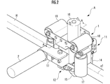
図2に示すように、移動補助装置Aは、手摺Rを保持する本体部1と、本体部1から側方に延設され、使用者Uに把持される、又は、荷物が固定される把持部2とを備えている。本体部1は、筒状に構成されており、その内部に手摺Rを挿入することによって、手摺Rを保持する。なお、ここで「筒状」とは、その軸線方向から見て、一部が開口している形状であってもよい。
図2及び図3に示すように、本体部1は、筐体10と、筐体10に水平方向に摺動自在に設けられた第1リンク機構11、筐体10に回動自在に設けられた第2リンク機構12と、筐体10に回転自在に軸支された駆動輪13(第1当接体)と、第1リンク機構11に回転自在に軸支された第1支持輪14(第2当接体)と、第2リンク機構12に回転自在に軸支された第2支持輪15(第3当接体)とを備えている。
移動補助装置Aでは、この駆動輪13、第1支持輪14及び第2支持輪15の各々が、本体部1の内周側で、互いに手摺Rの棒状部r1の周方向(すなわち、本体部1の周方向)にずれた位置で、手摺Rに対して当接して、手摺Rを保持している。
また、本体部1は、筐体10に載置されたアクチュエータ16(駆動源)と、第1リンク機構11に付勢力を加える一対の第1バネ17(第1の付勢機構)と、第2リンク機構12に付勢力を加える一対の第2バネ18(第2の付勢機構)とを備えている。
駆動輪13は、筐体10の内部で、回転自在に軸支されたゴム製のローラである。駆動輪13は、移動補助装置Aを手摺Rに取り付けた際に、上方側から、手摺Rの棒状部r1の上側の面であって、手摺Rの中心軸線である第1軸線a1の上方となる位置に当接する。
駆動輪13には、アクチュエータ16及び筐体10の内部に設けられたギヤ(不図示)を介して、駆動力が伝達される。その駆動力に応じて、駆動輪13は、手摺Rの棒状部r1の表面上で、手摺Rの軸線a1方向前方又は後方に転動する。なお、駆動輪13と筐体10との間にはサスペンション(不図示)が設けられており、駆動輪13の上下方向の移動も、ある程度許容可能となっている。
第1支持輪14は、第1リンク機構11の先端部に回転自在に軸支されたゴム製のローラである。また、第1支持輪14は、移動補助装置Aを手摺Rに取り付けた際に、水平方向一方側(図3では右側)から、手摺Rの棒状部r1の一方側の面であって、第1軸線a1の側方となる位置に当接する。また、第1支持輪14は、駆動輪13の移動に伴って、第1軸線a1に沿って、手摺Rの棒状部r1の表面を転動自在となっている。
ここで、第1リンク機構11は、移動補助装置Aを手摺Rに設置した際に、水平方向(具体的には、手摺Rの中心軸線である第1軸線a1を含み、上下方向に拡がる平面に対して直交する方向に、摺動自在に構成されている。
これにより、第1リンク機構11の先端部、及び、その先端部に支持されている第1支持輪14は、手摺Rの棒状部r1の周面に対して、水平方向一方側で離間自在となっている。すなわち、本体部1の軸線に対して、接近又は離間する方向に移動自在となっている。
また、第1リンク機構11に対しては、第1バネ17から、第1リンク機構11の先端部、及び、その先端部に支持されている第1支持輪14を、手摺Rの棒状部r1側(すなわち、本体部1の軸線側)に向かって付勢する付勢力が加えられている。
第2支持輪15は、第2リンク機構12の先端部に回転自在に軸支されたゴム製のローラである。また、第2支持輪15は、移動補助装置Aを手摺Rに取り付けた際に、水平方向他方側(図3では左側)から、手摺Rの棒状部r1の他方側の面であって、手摺Rと第1支持輪14との当接位置よりも下方となる位置に当接する。また、第2支持輪15は、駆動輪13の移動に伴って、第1軸線a1に沿って、手摺Rの棒状部r1の表面を転動自在となっている。
ここで、第2リンク機構12は、移動補助装置Aを手摺Rに設置した際に、手摺Rの中心軸線である第1軸線a1と平行であり、第1軸線a1に対して、上方且つ水平方向他方側に位置する軸線である第2軸線a2を中心として、回動自在に構成されている。
これにより、第2リンク機構12の先端部、及び、その先端部に支持されている第2支持輪15は、手摺Rの棒状部r1の周面に対して、水平方向他方側で離間自在となっている。すなわち、本体部1の軸線に対して、接近又は離間する方向に移動自在となっている。
また、第2リンク機構12に対しては、第2バネ18から、第2リンク機構12の先端部、及び、その先端部に支持されている第2支持輪15を、手摺Rの棒状部r1側(すなわち、本体部1の軸線側)に向かって付勢する付勢力が加えられている。
以上説明したように、移動補助装置Aでは、手摺Rを保持している駆動輪13、第1支持輪14及び第2支持輪15のうち、第1支持輪14及び第2支持輪15が、手摺Rに離間自在に当接するように構成されている。すなわち、手摺Rを保持するための空間が変動可能となっている。これにより、この移動補助装置Aでは、従来の移動補助装置のように、手摺を保持するための空間が所定の大きさに規定されているものに比べ、種々様々な径の太さ、断面形状の手摺を保持することができる。
また、一般に、既存の手摺には、棒状部から下方又は側方に向かって、支柱が延設されている。本実施形態における手摺Rも、棒状部r1の下方から側壁に延びる支持部r2を備えている。そして、移動補助装置Aを既存の手摺に適用するためには、手摺をしっかりと保持するとともに、手摺に沿って移動する際に、その支柱(支持部r2)を回避する必要がある。
そこで、移動補助装置Aは、駆動輪13を、上方側から、手摺Rの第1軸線a1の上方に当接させ、第1支持輪14を、水平方向一方側から、手摺Rの第1軸線a1の側方に当接させ、第2支持輪15を、水平方向他方側、且つ、下方から、手摺Rと第1支持輪14との当接位置よりも下方となる位置に当接させている。
これにより、移動補助装置Aは、手摺をしっかりと把持しつつ、手摺Rの水平方向他方側においては、第2支持輪15の上方側で、駆動輪13と第2支持輪15との間に広い間隔を確保することができ、また、手摺の下方側においては、第1支持輪14の下方側で、第1支持輪14と第2支持輪15との間に広い間隔を確保している。
その結果、移動補助装置Aを既存の手摺に適用し、移動補助装置Aが手摺に沿って移動する際に、それらの間隔を介して、既存の手摺から延設されている支柱を容易に回避することができるようになっている。本実施形態の移動補助装置Aでは、第1支持輪14と第2支持輪15との間の間隔を介して、手摺Rの支持部r2を回避している。
なお、本実施形態の移動補助装置Aでは、駆動機構であるアクチュエータ16からの駆動力によって、第1当接体である駆動輪13のみに駆動力が伝達されて転動し、第2当接体である第1支持輪14、及び、第3当接体である第2支持輪15は、駆動輪13の転動に伴って転動するように構成されている。
しかし、本発明における駆動機構は、このような構成に限定されるものではなく、駆動輪である第1当接体以外の当接体にも駆動力を伝達して、その当接体を転動させるように構成してもよい。具体的には、本実施形態における移動補助装置Aであれば、第1当接体である駆動輪13の他に、第2当接体である第1支持輪14、及び、第3当接体である第2支持輪15の少なくともいずれか一方にも駆動力を伝達して、転動させてもよい。
また、本実施形態の移動補助装置Aでは、第2当接体である第1支持輪14を、第1リンク機構11を介して、筐体10に対して摺動自在に構成するとともに、第3当接体である第2支持輪15を、第2リンク機構12を介して、筐体10に対して回動自在に構成することによって、それらの当接体を手摺Rに対して離間自在に構成している。
しかし、本発明において、当接体を支持する構造はこのような構成に限定されるものではなく、当接体を手摺に対して離間自在に支持する構造であればよい。
例えば、本実施形態の場合においては、第1支持輪14を回動自在に構成するとともに、第2支持輪15を水平方向に摺動自在に構成してもよい。また、第1支持輪14及び第2支持輪15の両方を、回動自在又は摺動自在に構成してもよい。また、第1支持輪14及び第2支持輪15の少なくともいずれか一方を、回動自在、且つ、摺動自在に構成してもよい。
次に、図4を参照して、移動補助装置Aが手摺Rの屈曲部分を通過する際における駆動輪13、第1支持輪14及び第2支持輪15の動作について説明する。
まず、移動補助装置Aが、手摺Rの直線状の部分を移動する場合について説明する。
この場合、図4の上段左端の図に示すように、移動補助装置Aが手摺Rの直線状の部分を移動する場合、駆動輪13は、手摺Rの第1軸線a1に沿って転動する。また、第1支持輪14及び第2支持輪15は、駆動輪13の転動に伴って、第1軸線a1に沿って移動する。
このとき、駆動輪13、第1支持輪14及び第2支持輪15の手摺Rの第1軸線a1からの距離は変化しない。そのため、駆動輪13、第1支持輪14及び第2支持輪15の相対位置も変化しない。
次に、移動補助装置Aが手摺Rの直線状の部分から、屈曲している部分まで移動する場合について説明する。
この場合、まず、図4の上段の最も左側の図、及び、左から2番目の図に示すように、直線状の部分から屈曲している部分に差し掛かった際に、第2支持輪15は、手摺Rの直線状の部分だけでなく、屈曲した後の部分に当接して、その移動速度が大幅に遅くなる。
一方で、駆動輪13は、アクチュエータ16から伝達された駆動力によって、前方に移動しようとし続ける。その結果、駆動輪13は、第2支持輪15よりも駆動輪13から離れた位置(図4では、第2支持輪15の左下側)にある点を中心として、回動し始める。また、第1支持輪14も、駆動輪13の回動に伴って、駆動輪13の回動中心となる点を中心として、回動し始める。
この回動の際、図4の上段最も左側の図、左から2番目の図、右から2番目の図、及び、最も右側の図に示すように、移動補助装置Aによって挟み込まれる手摺Rの幅は、徐々に増加していく。これに伴って、第1支持輪14と第2支持輪15との間隔も、徐々に広がっていく。より具体的には、駆動輪13と第1支持輪14との間隔、及び、駆動輪13及び第2支持輪15との間隔も、徐々に広がっていく。
ここで、移動補助装置Aでは、第1支持輪14は、第1リンク機構11(図3参照)によって、筐体10に対して水平方向に摺動自在に構成されており、第2支持輪15は、第2リンク機構12(図3参照)のよって、筐体10に対して回動自在に構成されている。すなわち、第1支持輪14及び第2支持輪15は、互いに独立して、筐体10に軸支されている駆動輪13との距離を、変動自在になっている。
そのため、この回動の際には、手摺Rの形状に応じて、駆動輪13と第1支持輪14との距離はそれほど急激には広がらず、一方で、駆動輪13と第2支持輪15との距離は急激に広がっていく。その結果、駆動輪13は、この回動の際にも、手摺Rの第1軸線a1から大きく外れることなく移動する。
また、ここで、第1支持輪14には、第1リンク機構11を介して、第1バネ17によって、手摺Rに向かって近づくような付勢力が加えられている。また、第2支持輪15には、第2リンク機構12を介して、第2バネ18によって、手摺Rに向かって近づくような付勢力が加えられている。
そのため、このように、駆動輪13と第1支持輪14との間隔及び駆動輪13と第2支持輪15との間隔が広がりつつ、且つ、回動する場合においても、駆動輪13、第1支持輪14及び第2支持輪15による手摺Rに対する保持力は維持される。
次に、移動補助装置Aが手摺Rの屈曲している部分から、直線状の部分まで移動する場合について説明する。
この場合、まず、図4の上段最も右側の図、及び、下段左側の図に示すように、屈曲している部分から直線状の部分に差し掛かった際に、第2支持輪15は、手摺Rの屈曲した部分から屈曲した後の直線状の部分に移動しつつ、その移動速度は通常の移動速度に徐々に戻ることになる。
一方で、駆動輪13は、引き続き、第2支持輪15よりも、駆動輪13から離れた位置(図4では、第2支持輪15の左下側)にある点を中心として回動を続ける。また、第1支持輪14も、駆動輪13の回動に伴って移動して、駆動輪13の回動中心となる点を中心として回動を続ける。
この回動の際、図4の上段最も右側の図、下段左側の図、中央の図、及び、右側の図に示すように、移動補助装置Aによって挟み込まれる手摺Rの幅は、徐々に減少していく。これに伴って、第1支持輪14と第2支持輪15との間隔も、徐々に狭まっていく。より具体的には、駆動輪13と第1支持輪14との間隔、及び、駆動輪13及び第2支持輪15との間隔も、徐々に狭まっていく。
ここで、上述したように、移動補助装置Aでは、第1支持輪14は、第1リンク機構11(図3参照)によって、筐体10に対して回動自在に構成されており、第2支持輪15は、第2リンク機構12(図3参照)のよって、筐体10に対して回動自在に構成されている。すなわち、第1支持輪14及び第2支持輪15は、互いに独立して、筐体10に軸支されている駆動輪13との距離を、変動自在になっている。
そのため、この回動の際には、手摺Rの形状に応じて、駆動輪13と第1支持輪14との距離はそれほど急激に狭まらず、一方で、駆動輪13と第2支持輪15との距離は急激に狭まっていく。その結果、駆動輪13は、この回動の際にも、手摺Rの第1軸線a1から大きく外れることなく移動する。
また、ここで、上述したように、第1支持輪14には、第1リンク機構11を介して、第1バネ17によって、手摺Rに向かって近づくような付勢力が加えられている。また、第2支持輪15には、第2リンク機構12を介して、第2バネ18によって、手摺Rに向かって近づくような付勢力が加えられている。
そのため、このように、駆動輪13と第1支持輪14との間隔及び駆動輪13と第2支持輪15との間隔が狭まりつつ、且つ、回動する場合においても、駆動輪13、第1支持輪14及び第2支持輪15による手摺Rに対する保持力は維持される。
以上説明したように、移動補助装置Aでは、手摺Rを保持した状態で駆動輪13、第1支持輪14及び第2支持輪15が移動させられたとしても、直線状の部分であっても屈曲している部分であっても(すなわち、手摺Rの径の大きさによらず)、その保持力が維持される。
その結果、この移動補助装置Aは、屈曲するように折れ曲がっていて、径の大きさが変化する手摺Rあっても、その手摺Rを保持した状態のまま、その径の大きさが変化する部分を移動することができる。
ところで、本実施形態においては、手摺Rが左に向かって屈曲している。しかし、移動補助装置Aでは、手摺Rの直線状の部分を移動する場合であっても、折れ曲がった部分を移動する場合であっても、駆動輪13は、手摺Rの第1軸線a1から大きく離れずに移動している。
これは、第1支持輪14に対して付勢力を加える第1バネ17の付勢力を、第2支持輪15に対して付勢力を加える第2バネ18の付勢力よりも小さく設定することによって、折れ曲がった部分を移動する際に、第1支持輪14を第2支持輪15よりも移動しやすくしているためである。
これにより、移動補助装置Aでは、駆動輪13を手摺Rの第1軸線a1の上方に載置した状態を、安定して維持することができるようになっている。すなわち、駆動輪13を手摺Rの第1軸線a1の上方に対して安定して当接させることができるようになっている。
その結果、移動補助装置Aでは、手摺Rの第1軸線a1方向に移動するための力(すなわち、使用者Uの移動を補助するための力)を安定したものとすることができるようになっている。
なお、本発明の移動補助装置は、第1の付勢部材及び第2の付勢部材の付勢力は、このような構成に限定されるものではない。
例えば、図4の手摺Rとは異なり、手摺が右に向かって屈曲しているものである場合には、本実施形態の移動補助装置Aにおける第2支持輪15に対して付勢力を加える第2バネの付勢力を、第1支持輪14に対して付勢力を加える第1バネの付勢力よりも小さく設定するとよい。
また、例えば、後述する図5に示す変形例に係る移動補助装置Aのように、補助アーム3を備える構成である場合、又は、手摺の径の大きさの変化があまり大きくない場合には、第1の付勢部材及び第2の付勢部材を同程度にしてもよい。
なお、本実施形態の移動補助装置Aでは、当接体として手摺Rの第1軸線a1に沿って転動可能なゴム製のローラを採用している。これは、そのようなローラであれば、周方向への移動が阻害されるので、移動補助装置A全体が第1軸線a1周りに回転してしまうことを防止できるためである。また、材料としてゴムを採用しているのは、手摺Rの表面の損傷を防止するためである。
しかし、本発明における当接体は、そのような構成に限定されるものではなく、手摺の表面に当接した状態で、手摺の表面上を手摺の軸線方向に移動可能なものであればよい。例えば、無限軌道等のローラとは異なる転動体、テフロン(登録商標)加工された球等であってもよい。
また、本実施形態の移動補助装置Aでは、第2当接体である第1支持輪14及び第3当接体である第2支持輪15の両方が、手摺Rに対して離間自在に構成されている。しかし、本発明の移動補助装置はそのような構成に限定されるものではなく、第2当接体及び第3当接体のいずれか一方のみが、手摺に対して離間自在であってもよい。
また、本実施形態の移動補助装置Aでは、駆動輪13、第1支持輪14及び第2支持輪15の3つの当接体を用いて、手摺Rを支持している。しかし、本発明の移動補助装置は、そのような構成に限定されるものではなく、少なくとも3つの当接体を備えていればよい。例えば、4つ以上の当接体を備えていてもよい。
また、本実施形態の移動補助装置Aでは、駆動輪13を、上方側から、手摺Rの第1軸線a1の上方に当接させ、第1支持輪14を、水平方向一方側から、手摺Rの第1軸線a1の側方に当接させ、第2支持輪15を、水平方向他方側、且つ、下方から、手摺Rと第1支持輪14との当接位置よりも下方となる位置に当接させている。
しかし、本発明の移動補助装置は、そのような構成に限定されるものではなく、手摺を保持できるような配置であれば、当接体をどのように配置してもよい。例えば、3つの当接体を等間隔に配置してもよい。
また、本実施形態の移動補助装置Aでは、当接体である転動体13を構成するローラの周面は平面になっている。これは、取り付ける手摺の径の大きさによっては、手摺の屈している曲部分を通過する際に、駆動輪13がその手摺の上面を水平方向に移動しなければ、スムーズな移動が阻害されてしまうおそれがあるためである。
しかし、本発明の移動補助装置は、そのような構成に限定されるものではなく、当接体の周面(当接部分)の形状は、適宜設計してかまわない。例えば、設置する手摺の径が予め定められたものである場合には、その手摺の周面の形状に対応させて、当接体の当接部分の形状を設定してもよい。
ところで、駆動輪13、第1支持輪14及び第2支持輪15が手摺Rを保持する力、又は、駆動輪13、第1支持輪14及び第2支持輪15が手摺Rの表面上を手摺Rの第1軸線a1に沿って移動する力は、その第1支持輪14及び第2支持輪15を手摺Rに向かって付勢する第1バネ17及び第2バネ18の付勢力によって増減する。
そこで、移動補助装置Aでは、第1支持輪14及び第2支持輪15の位置によらず、第1支持輪14及び第2支持輪15に対して一定の荷重を加えることができるように、第1バネ17及び第2バネ18として、定荷重バネを採用している。
これにより、移動補助装置Aでは、保持力及び駆動力の安定化を図っている。ひいては、移動補助装置Aが手摺Rの第1軸線a1方向に移動するための力(すなわち、使用者Uの移動を補助するための力)の安定化を図っている。
なお、移動補助装置Aでは、簡易な構成でありながら、一定の荷重を安定して加えることができるので、付勢機構として、定荷重バネを採用している。しかし、一定の荷重を安定して加えること(すなわち、保持力及び駆動力の安定化)は、定荷重バネのみにより実現し得るものではなく、第1支持輪14及び第2支持輪15の位置によらず、第1支持輪14及び第2支持輪15に対して一定の荷重を加えることができる付勢機構であれば、実現し得る。
具他的には、例えば、アクチュエータとそのアクチュエータの駆動力を制御するための制御装置とによって付勢機構を構成し、アクチュエータの駆動力に基づく荷重が一定となるように、その駆動力を制御するようにしてもよい。
また、本発明における付勢機構は、このような構成に限定されるものではなく、手摺に離間自在に当接する当接体を、手摺側に向かって付勢するものであればよい。そのため、必ずしも、手摺に離間自在に当接する当接体の位置によらず、当接体に対して一定の荷重を加えるものである必要はなく、当接体の位置によって、荷重が異なるものであってもよい。
また、ところで、移動補助装置Aは、駆動輪13、第1支持輪14及び第2支持輪15で手摺Rを保持することによって、通常の使用範囲における力(具体的には、例えば、使用者Uの移動を補助する際に加わる力、通常の荷物をぶら下げた際に加わる力等)が加えられたとしても、手摺Rの第1軸線a1周りに意図せず回動してしまうことは、十分に抑制できている。
しかし、使用者Uが転倒したり、非常に重い荷物をぶら下げたりした際には、通常の使用範囲における力を超える力が加わり、手摺補助装置Aが手摺Rの第1軸線a1周りに意図せず回動してしまう可能性がある。そこで、図5に示す変形例のように、本体部1から下方に延びる補助アーム3を設けてもよい。
このような補助アーム3を設けると、例えば、手摺Rが上方に位置する第1手摺R1と、下方に位置する第2手摺R2とで構成されるものであり、第1手摺R1に移動補助装置Aを取り付けた場合には、補助アーム3が第2手摺R2に当接することになる。
これにより、移動補助装置Aが意図せず回動してしまった場合であっても、補助アーム3と第2手摺R2との当接によって、それ以上の回動を抑制することができる。ひいては、使用者Uのそれ以上の転倒、ぶら下げた荷物の落下を防止することができる。
また、補助アーム3を設けた場合、手摺Rが設けられている側壁Wの表面形状等によっては、その側壁W等と補助アーム3との間の摩擦によって、移動補助装置Aの移動が阻害されてしまうおそれがある。
そこで、図6に示すように、補助アーム3の先端部の手摺Rが敷設されている側壁W側には、手摺Rの第1軸線a1方向に沿って転動自在な補助ローラ3a(補助転動体)を設けることが好ましい。このように構成すると、補助アーム3と側壁Wとの間の摩擦を低減することができるので、その摩擦によって移動補助装置Aの移動が阻害されにくくなる。
なお、本発明における補助アームは、移動補助装置の回動を抑制できるものあればよい。そのため、必ずしも鉛直方向下方に延設される必要はなく、下方且つ側壁側に向かって斜めに延設されていたり、途中で屈曲していたりしているものであってもよい。また、当接する手摺、側壁等表面形状がなだらかであったり、補助アームの素材が滑らかなものであったりして、手摺、側壁と補助アームとの間の摩擦が十分に小さい場合等には、補助転動体を省略してもよい。
以上、図示の実施形態について説明したが、本発明はこのような形態に限られるものではない。
例えば、上記実施形態では、当接体としてローラを採用しているが、本発明の当接体は、そのような構成に限定されるものではなく、手摺の表面に当接した状態で、手摺の表面上を手摺の軸線方向に移動可能なものであればよい。例えば、無限軌道等のローラとは異なる転動体、テフロン(登録商標)加工された球等であってもよい。
1…本体部、2…把持部、3…補助アーム、3a…補助ローラ(補助転動体)、10…筐体、11…第1リンク機構、12…第2リンク機構、13…駆動輪(第1当接体)、14…第1支持輪(第2当接体)、15…第2支持輪(第3当接体)、16…アクチュエータ(駆動機構)、17…第1バネ(第1の付勢機構)、18…第2バネ(第2の付勢機構)、A…移動補助装置、C…廊下、U…使用者、R…手摺、R1…第1手摺、R2…第2手摺、S…階段、W…側壁、a1…第1軸線、a2…第2軸線、r1…棒状部、r1…支持部。
Claims (8)
- 手摺を保持する本体部と、前記本体部から延設された把持部とを備え、前記手摺に沿って移動して使用者の移動を補助する移動補助装置であって、
前記本体部に支持され、各々が互いに前記手摺の周方向にずれた位置で前記手摺に当接して前記手摺を保持するとともに、前記手摺の表面上で前記手摺の軸線方向に移動自在な第1当接体、第2当接体及び第3当接体と、
前記第1当接体に駆動力を伝達し、前記第1当接体を移動させる駆動機構とを備え、
前記第1当接体、前記第2当接体及び前記第3当接体の少なくとも1つの当接体は、前記手摺に離間自在であり、
前記本体部は、前記手摺に離間自在に当接する前記当接体を、前記手摺側に向かって付勢する付勢機構を有していることを特徴とする移動補助装置。 - 請求項1に記載の移動補助装置において、
前記第1当接体は、前記手摺の上方側から、前記手摺に当接し、
前記第2当接体は、前記手摺の水平方向一方側で、前記手摺に離間自在であり、
前記第3当接体は、前記手摺の水平方向他方側で、前記手摺に離間自在であり、
前記本体部は、前記第2当接体を前記手摺側に向かって付勢する第1の付勢機構と、前記第3当接体を前記手摺側に向かって付勢する第2の付勢機構とを有していることを特徴とする移動補助装置。 - 請求項1又は請求項2に記載の移動補助装置において、
前記付勢機構は、前記手摺に離間自在に当接する前記当接体の位置によらず、前記当接体に対して一定の荷重を加えることを特徴とする移動補助装置。 - 請求項3に記載の移動補助装置において、
前記付勢機構は、定荷重バネを用いて構成されていることを特徴とする移動補助装置。 - 請求項1~請求項4のいずれか1項に記載の移動補助装置において、
前記第1当接体は、前記手摺の上方側から、前記手摺の中心軸線の上方で、前記手摺に当接し、
前記第2当接体は、前記手摺の水平方向一方側から、前記中心軸線の側方で、前記手摺に当接し、
前記第3当接体は、前記手摺の水平方向他方側から、前記手摺と前記第2当接体との当接位置よりも下方で、前記手摺に当接し、
前記第2当接体及び前記第3当接体の少なくとも一方は、前記手摺に離間自在であることを特徴とする移動補助装置。 - 請求項1~請求項5のいずれか1項に記載の移動補助装置において、
前記本体部のから下方に延設された補助アームを備えていることを特徴とする移動補助装置。 - 請求項6に記載の移動補助装置において、
前記補助アームは、前記手摺の軸線方向に沿って転動自在な補助転動体を有していることを特徴とする移動補助装置。 - 手摺を挿入するようにして前記手摺を保持する筒状の本体部と、前記本体部から延設された把持部とを備え、前記手摺に沿って移動して前記把持部を介して使用者の移動を補助する移動補助装置であって、
前記本体部の内周側に支持され、互いに周方向にずれた位置に位置する第1当接体、第2当接体及び第3当接体と、
前記第1当接体に駆動力を伝達し、前記第1当接体を前記本体部の軸線方向に移動させる駆動機構とを備え、
前記第1当接体、前記第2当接体及び前記第3当接体の少なくとも1つの当接体は、前記本体部の軸線に対して接近又は離間する方向に移動自在であり、
前記本体部は、前記軸線に対して移動自在な前記当接体を、前記軸線側に向かって付勢する付勢機構を有していることを特徴とする移動補助装置。
Priority Applications (1)
| Application Number | Priority Date | Filing Date | Title |
|---|---|---|---|
| JP2020558095A JP7039729B2 (ja) | 2018-11-20 | 2019-08-22 | 移動補助装置 |
Applications Claiming Priority (2)
| Application Number | Priority Date | Filing Date | Title |
|---|---|---|---|
| JP2018217426 | 2018-11-20 | ||
| JP2018-217426 | 2018-11-20 |
Publications (1)
| Publication Number | Publication Date |
|---|---|
| WO2020105238A1 true WO2020105238A1 (ja) | 2020-05-28 |
Family
ID=70773939
Family Applications (1)
| Application Number | Title | Priority Date | Filing Date |
|---|---|---|---|
| PCT/JP2019/032808 Ceased WO2020105238A1 (ja) | 2018-11-20 | 2019-08-22 | 移動補助装置 |
Country Status (2)
| Country | Link |
|---|---|
| JP (1) | JP7039729B2 (ja) |
| WO (1) | WO2020105238A1 (ja) |
Cited By (1)
| Publication number | Priority date | Publication date | Assignee | Title |
|---|---|---|---|---|
| CN112690607A (zh) * | 2020-10-16 | 2021-04-23 | 田四九 | 一种婴儿楼梯辅助防摔装置 |
Citations (2)
| Publication number | Priority date | Publication date | Assignee | Title |
|---|---|---|---|---|
| US20060242917A1 (en) * | 2005-03-04 | 2006-11-02 | Boris Usherovich | Stairs assistance device |
| JP2007146621A (ja) * | 2005-08-17 | 2007-06-14 | Jiro Okuno | 階段歩行用介助装置 |
-
2019
- 2019-08-22 JP JP2020558095A patent/JP7039729B2/ja active Active
- 2019-08-22 WO PCT/JP2019/032808 patent/WO2020105238A1/ja not_active Ceased
Patent Citations (2)
| Publication number | Priority date | Publication date | Assignee | Title |
|---|---|---|---|---|
| US20060242917A1 (en) * | 2005-03-04 | 2006-11-02 | Boris Usherovich | Stairs assistance device |
| JP2007146621A (ja) * | 2005-08-17 | 2007-06-14 | Jiro Okuno | 階段歩行用介助装置 |
Cited By (2)
| Publication number | Priority date | Publication date | Assignee | Title |
|---|---|---|---|---|
| CN112690607A (zh) * | 2020-10-16 | 2021-04-23 | 田四九 | 一种婴儿楼梯辅助防摔装置 |
| CN112690607B (zh) * | 2020-10-16 | 2022-08-05 | 伊春市福林木业有限责任公司 | 一种婴儿楼梯辅助防摔装置 |
Also Published As
| Publication number | Publication date |
|---|---|
| JP7039729B2 (ja) | 2022-03-22 |
| JPWO2020105238A1 (ja) | 2021-09-02 |
Similar Documents
| Publication | Publication Date | Title |
|---|---|---|
| JP5826843B2 (ja) | 単ベルト全方向トレッドミル | |
| JP2015169876A5 (ja) | ||
| JP6337324B2 (ja) | 管内走行装置 | |
| CA2465474A1 (en) | Conveyance apparatus using movable bodies | |
| JP2014159336A5 (ja) | ||
| JPWO2018131329A1 (ja) | 壁面吸着走行装置 | |
| WO2020105238A1 (ja) | 移動補助装置 | |
| JP2016020999A5 (ja) | ||
| TW200925093A (en) | Meander correction device of web | |
| JP2014220989A5 (ja) | 駆動装置、画像振れ補正装置、交換レンズ、撮像装置、及び自動ステージ | |
| KR20190051421A (ko) | 자세 교정용 슬링바를 구비한 보행 재활 훈련 장치 | |
| US20110146736A1 (en) | Walker | |
| US4946158A (en) | Baby walker | |
| JP6474901B2 (ja) | 軸方向力を増幅するための携帯用の装置及びこの装置を有する下方外骨格 | |
| TWI597433B (zh) | 滑軌總成及其助滑裝置 | |
| JP3174724U (ja) | 視覚障害者用杖 | |
| EP2457802A2 (en) | Manually directionally controlled transporting apparatus | |
| JP6087225B2 (ja) | 搬送体 | |
| RU2505447C2 (ru) | Шар-колесо калинкина | |
| TWI637894B (zh) | Tension adjustment system | |
| JP7027665B2 (ja) | 搬送装置および搬送方法 | |
| JP6270621B2 (ja) | 管内走行装置 | |
| JP2008043558A (ja) | 歩行補助装置 | |
| JP6179393B2 (ja) | 歩行訓練システム | |
| JP2019138366A (ja) | 運動案内装置 |
Legal Events
| Date | Code | Title | Description |
|---|---|---|---|
| 121 | Ep: the epo has been informed by wipo that ep was designated in this application |
Ref document number: 19886738 Country of ref document: EP Kind code of ref document: A1 |
|
| ENP | Entry into the national phase |
Ref document number: 2020558095 Country of ref document: JP Kind code of ref document: A |
|
| NENP | Non-entry into the national phase |
Ref country code: DE |
|
| 122 | Ep: pct application non-entry in european phase |
Ref document number: 19886738 Country of ref document: EP Kind code of ref document: A1 |