WO2020105203A1 - 外圧式濾過モジュール - Google Patents
外圧式濾過モジュールInfo
- Publication number
- WO2020105203A1 WO2020105203A1 PCT/JP2019/021144 JP2019021144W WO2020105203A1 WO 2020105203 A1 WO2020105203 A1 WO 2020105203A1 JP 2019021144 W JP2019021144 W JP 2019021144W WO 2020105203 A1 WO2020105203 A1 WO 2020105203A1
- Authority
- WO
- WIPO (PCT)
- Prior art keywords
- holding member
- filtration module
- support
- external pressure
- pressure type
- Prior art date
- Legal status (The legal status is an assumption and is not a legal conclusion. Google has not performed a legal analysis and makes no representation as to the accuracy of the status listed.)
- Ceased
Links
Images



Classifications
-
- Y—GENERAL TAGGING OF NEW TECHNOLOGICAL DEVELOPMENTS; GENERAL TAGGING OF CROSS-SECTIONAL TECHNOLOGIES SPANNING OVER SEVERAL SECTIONS OF THE IPC; TECHNICAL SUBJECTS COVERED BY FORMER USPC CROSS-REFERENCE ART COLLECTIONS [XRACs] AND DIGESTS
- Y02—TECHNOLOGIES OR APPLICATIONS FOR MITIGATION OR ADAPTATION AGAINST CLIMATE CHANGE
- Y02A—TECHNOLOGIES FOR ADAPTATION TO CLIMATE CHANGE
- Y02A20/00—Water conservation; Efficient water supply; Efficient water use
- Y02A20/124—Water desalination
- Y02A20/131—Reverse-osmosis
Definitions
- the present disclosure relates to external pressure filtration modules.
- This application claims priority based on Japanese application No. 2018-216500 filed on November 19, 2018, and incorporates all the contents described in the Japanese application.
- Filtration modules are used in desalination of seawater, manufacturing process of industrial pure water, wastewater treatment process such as reuse of wastewater, etc.
- this filtration module one having a tubular casing and a filtration membrane arranged in this casing is widely used.
- the filtration membrane a hollow fiber membrane, a spiral membrane, a flat membrane, a tubular membrane or the like is used, and many hollow fiber membranes that easily increase the membrane area per module are adopted.
- an external pressure type filtration module in which a cartridge having a plurality of hollow fiber membranes is detachably arranged in a casing (casing) has been proposed (International Publication No. 2015 / 098266).
- a cartridge and a rectifying cylinder are detachably stored in a housing.
- the cartridge comprises a plurality of hollow fiber membranes, a first focusing and fixing part (upper holding member) that fixes the upper ends of the plurality of hollow fiber membranes, and a second focusing and fixing part that fixes the lower ends of the plurality of hollow fiber membranes.
- the casing includes a cylindrical casing body, an upper cap connected to an upper opening of the casing body and having a filtrate outlet, and a lower cap connected to a lower opening of the casing body and having a stock solution inlet. have.
- the flow straightening cylinder has a flange portion projecting outward in the radial direction at the upper end and a convex portion projecting radially inward from the inner peripheral surface of the upper portion.
- the external pressure type filtration module described in the above publication is configured to introduce the stock solution into the housing from the stock solution inlet of the housing and to discharge the filtered water that has passed through the plurality of hollow fiber membranes from the filtered solution outlet.
- the flange portion of the flow straightening cylinder is sandwiched between the upper end surface of the housing body and the lower end surface of the upper cap, and further, the first portion is provided on the convex portion of the flow straightening cylinder via the sealing material.
- the external pressure type filtration module includes a plurality of hollow fiber membranes that are vertically aligned, a tubular casing that stores the plurality of hollow fiber membranes, and the plurality of hollow fibers in the casing.
- An external pressure type filtration module comprising an upper holding member for fixing the upper end of the membrane and a lower holding member for fixing the lower end, further comprising a support member for maintaining a space between the upper holding member and the lower holding member, The support member has a metal support pipe bridged between the upper holding member and the lower holding member.
- FIG. 1 is a schematic view showing an external pressure type filtration module according to an embodiment of the present invention.
- FIG. 2 is an enlarged cross-sectional view of the external pressure type filtration module of FIG. 1 taken along the line AA.
- FIG. 3 is an end view of the external pressure type filtration module of FIG. 2 taken along the line BB.
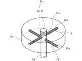
- FIG. 4 is a schematic perspective view showing the upper structure of the support member of the external pressure type filtration module of FIG. 1.
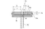
- FIG. 5 is a schematic cross-sectional view showing a fixed state of the support member and the upper holding member of the external pressure type filtration module of FIG. 1.
- FIG. 6 is a schematic perspective view showing the lower structure of the support member of the external pressure type filtration module of FIG. 1.
- the conventional external pressure filtration module described above causes membrane fouling as the filtration process proceeds. Therefore, in such an external pressure type filtration module, backwashing is usually carried out by introducing washing water from a filtered water outlet (filtrate outlet) at a predetermined frequency.
- the present inventor diligently studied storing a cartridge having a plurality of hollow fiber membranes in a casing such as an existing reverse osmosis membrane vessel that does not have a structure for fixing an upper holding member.
- the present disclosure has been made under such circumstances, and an object thereof is to provide an external pressure type filtration module capable of appropriately maintaining the interval between the upper holding member and the lower holding member.
- An external pressure type filtration module includes a plurality of hollow fiber membranes that are vertically aligned, a tubular casing that stores the plurality of hollow fiber membranes, and the plurality of hollow fiber membranes in the casing.
- An external pressure type filtration module comprising an upper holding member for fixing the upper end of the hollow fiber membrane and a lower holding member for fixing the lower end of the hollow fiber membrane, the supporting member maintaining a space between the upper holding member and the lower holding member. Further, the support member further includes a metal support pipe bridged between the upper holding member and the lower holding member.
- the support member for maintaining the space between the upper holding member and the lower holding member has the metal support pipe bridged between the upper holding member and the lower holding member, back washing is performed. Even when a backwash pressure is applied to the upper holding member from above, the upper holding member and the lower holding member can be appropriately maintained at a predetermined interval.
- the upper holding member and the lower holding member are preferably made of synthetic resin as a main component and have a fixing portion that is fixed to the support pipe and the plurality of hollow fiber membranes.
- the upper holding member and the lower holding member have a fixing portion that is made of a synthetic resin as a main component and is fixed to the support pipe and the plurality of hollow fiber membranes.
- the hollow fiber membrane can be easily fixed to the upper holding member and the lower holding member.
- the support member has a connecting portion that extends in the radial direction of the support pipe from the upper end portion and the lower end portion of the support pipe and is fixed to the fixing portion.
- the support member has the connecting portion that extends from the upper end portion and the lower end portion of the support pipe in the radial direction of the support pipe and is fixed to the fixing portion, and thus the supporting member and the fixing portion are It is possible to increase the contact area and increase the adhesive strength between the support member and the fixing portion.
- the connection part may include one or a plurality of support rods that are arranged to penetrate the support pipe in the radial direction.
- the connection portion includes one or a plurality of support rods that are arranged to penetrate the support pipe in the radial direction, so that the one or a plurality of support rods has a predetermined axial direction of the support pipe. Easy and secure in position. With this, by fixing the one or more support rods and the fixing portion to each other, the fixing portion can be easily fixed to the support pipe via the one or more support rods.
- the connecting portion includes a plurality of the support rods penetrating at least one of the upper end portion and the lower end portion of the support pipe, and the support rods are radially arranged in a plan view.
- the connection portion includes a plurality of the support rods penetrating at least one of the upper end portion and the lower end portion of the support pipe, and the support rods are radially arranged in a plan view, and thus the plurality of the support rods are provided.
- the fixing portion can be easily and surely fixed to the support pipe via the support rod.
- the above-mentioned support pipe and one or a plurality of support rods may contain the same kind of metal as a main component.
- the supporting pipe and the one or more supporting rods are mainly composed of the same kind of metal, so that the fixing portion can be easily fixed to the supporting pipe while preventing corrosion of the metal.
- the contact area between the support rod and the fixing portion is increased, and the adhesive strength between the support member and the fixing portion is further increased.
- the supporting member has a synthetic resin as a main component, extends from at least one of an upper end and a lower end of the supporting pipe, and has an extending piece fixed to the fixing portion.
- the support member has a synthetic resin as a main component, has an extending piece that extends from at least one of the upper end and the lower end of the support pipe, and is fixed to the fixing portion, so that the supporting member is made of synthetic resin.
- the extending piece, which is the main component, and the fixing portion are firmly fixed to each other. Thereby, the fixing portion can be easily and surely fixed to the support pipe via the extension piece.
- the extending piece has one or more grooves on the fixing surface with the fixing portion.
- the extension piece has one or a plurality of grooves on the fixing surface with the fixing portion, so that the contact area between the extension piece and the fixing portion is increased, and the supporting member and the fixing portion are formed.
- the adhesive strength of can be increased.
- the upper holding member has a tubular frame body and the fixing portion that fills the internal space of the frame body, and the casing is detachably fitted onto the frame body.
- the upper holding member and the lower holding member can be appropriately maintained at the predetermined intervals by the support member. Therefore, even in the configuration in which the casing is detachably fitted onto the cylindrical frame body, the entanglement of the plurality of hollow fiber membranes due to the small distance between the upper holding member and the lower holding member, etc. Can be prevented.
- the “main component” means a component having the largest content in terms of mass, for example, a component having a content of 50 mass% or more, preferably 70 mass% or more, more preferably 90 mass% or more.
- the external pressure type filtration module of FIGS. 1 to 3 includes a plurality of hollow fiber membranes 1 aligned in the vertical direction, a tubular casing 2 for storing the plurality of hollow fiber membranes 1, and a plurality of hollow fiber membranes in the casing 2. Between the upper holding member 3 for fixing the upper ends of the hollow fiber membranes 1, the lower holding member 4 for fixing the lower ends of the plurality of hollow fiber membranes 1 in the casing 2, and the upper holding member 3 and the lower holding member 4. And a supporting member 5 for maintaining the interval of.
- the support member 5 has a metal support pipe 5 a that is bridged between the upper holding member 3 and the lower holding member 4.
- the external pressure type filtration module has a rectifying cylinder 6 which is connected to the upper holding member 3 and surrounds the upper portions of the plurality of hollow fiber membranes 1 in the casing 2.
- the external pressure type filtration module is used in a membrane separation device that removes impurities from the stock solution S1 and discharges the filtered water F.
- the external pressure type filtration module is used, for example, in a microfiltration device, an ultrafiltration device, a reverse osmosis device, or the like. From the viewpoint of utilizing an existing casing, the external pressure type filtration module is preferably used for a reverse osmosis device using a reverse osmosis membrane vessel (RO vessel) which is relatively expensive and has a simple shape.
- RO vessel reverse osmosis membrane vessel
- the support member 5 for maintaining the space between the upper holding member 3 and the lower holding member 4 has a metal support pipe 5a bridged between the upper holding member 3 and the lower holding member 4. Therefore, even when a backwash pressure is applied to the upper holding member 3 from above during backwashing, the upper holding member 3 and the lower holding member 4 can be appropriately maintained at a predetermined interval.
- the plurality of hollow fiber membranes 1, the upper holding member 3, and the lower holding member 4 are configured as a cartridge that can be attached to and detached from the casing 2. That is, the upper holding member 3 and the lower holding member 4 are not bonded to the inner peripheral surface of the casing 2.
- the space between the upper holding member 3 and the lower holding member 4 is a supporting member. Since it is maintained by 5, the entanglement of the plurality of hollow fiber membranes 1 can be appropriately prevented.
- the casing 2 has a body 2a having a substantially uniform inner diameter in the axial direction, a lid 2b connected to the upper end of the body 2a, and a bottom 2c connected to the lower end of the body 2a.
- the body 2a has, for example, a cylindrical shape.
- the body 2a has a central axis arranged vertically.
- the upper holding member 3 is detachably connected to the inner peripheral surface of the body portion 2a. In other words, the upper holding member 3 is detachably connected to the smooth surface of the casing 2.
- the body portion 2a has a stock solution discharge port 10 on the upper portion of the peripheral wall.
- the lid portion 2b is detachably connected to the body portion 2a.
- the lid portion 2b has a filtered water discharge port 11 capable of discharging the filtered water F that has permeated the plurality of hollow fiber membranes 1.
- the bottom portion 2c has a funnel shape in which the diameter is reduced downward, and has a stock solution inlet 12 at the lower end portion for introducing the stock solution S1 into the casing 2. Further, the bottom portion 2c has a pedestal portion 13 that supports the lower holding member 4 from below at the upper end portion. The pedestal portion 13 is formed in an annular shape in a plan view so that the outer peripheral portion of the lower surface of the lower holding member 4 can be supported from below.
- an existing specification can be used, and for example, an RO vessel containing fiber reinforced plastic and excellent in heat resistance, pressure resistance, etc. can be used.
- the inner diameter is substantially uniform means that the ratio of the maximum value to the minimum value of the inner diameter in the axial direction is 1.00 or more and 1.10 or less, and preferably 1.00 or more and 1.05 or less. It means that.
- the stock solution S1 is introduced into the casing 2 through the stock solution inlet 12, and the plurality of hollow fiber membranes 1 are permeated while preventing the permeation of impurities on the outer peripheral surface of the plurality of hollow fiber membranes 1.
- the filtered water F is discharged from the filtered water discharge port 11 to perform the filtering process.
- the external pressure type filtration module is configured to discharge the stock solution S2 containing impurities that have not permeated the plurality of hollow fiber membranes 1 from the stock solution discharge port 10.
- the external pressure type filtration module when impurities adhere to the outer peripheral surfaces of the plurality of hollow fiber membranes 1 as the filtration process is performed, cleaning water is introduced into the casing 2 from the filtered water discharge port 11, and the cleaning water is introduced.
- the reverse cleaning is performed by permeating a plurality of hollow fiber membranes 1 from the inner peripheral surface side to the outer peripheral surface side.
- the hollow fiber membrane 1 preferably contains a thermoplastic resin as a main component.
- the main component of the hollow fiber membrane 1 include polyethylene, polypropylene, polyvinylidene fluoride, ethylene-vinyl alcohol copolymer, polyamide, polyimide, polyetherimide, polystyrene, polysulfone, polyvinyl alcohol, polyphenylene ether, polyphenylene sulfide, and cellulose acetate.
- PTFE which is excellent in mechanical strength, chemical resistance, heat resistance, weather resistance, incombustibility, etc. and is porous, is preferable, and uniaxially or biaxially stretched PTFE is more preferable.
- the hollow fiber membrane 1 has a large number of holes penetrating in the thickness direction.
- the average pore size of these pores can be appropriately set according to the application of the external pressure type filtration module, and can be, for example, about 5 nm or more and 10 ⁇ m or less, and the external pressure type filtration module is used for a reverse osmosis device. In this case, for example, it can be 0.5 nm or more and 2 nm or less.
- the “average pore diameter” means the average value of arbitrary 10 pore diameters.
- the upper holding member 3 has a tubular frame 3a and an upper fixing portion 3b filled in the internal space of the frame 3a.
- the frame body 3 a has a cylindrical main body 14 having an outer diameter substantially equal to the inner diameter of the body portion 2 a of the casing 2, and a ring-shaped sealing material 15 fitted to the outer peripheral surface of the main body 14 over the entire circumference of the main body 14.
- a groove 14a is formed on the outer peripheral surface of the main body 14 over the entire circumference thereof, and the sealing material 15 is fitted in the groove 14a.
- the main body 14 is made of, for example, a synthetic resin as a main component.
- a synthetic resin as a main component, the main body 14 can increase the adhesive strength with the upper fixing portion 3b. This allows the external pressure type filtration module to firmly fix the entire upper holding member 3 to the support member 5.
- the synthetic resin include polyolefin such as polypropylene and polyethylene, acrylonitrile-butadiene-styrene copolymer (ABS resin), polyvinyl chloride, polycarbonate, acrylic resin, polysulfone, polyacetal, polyimide, modified polyphenylene oxide, polytetrafluoroethylene. And other fluororesins.
- ABS resin having excellent pressure resistance and excellent adhesiveness when an epoxy resin is used as a main component of the upper fixing portion 3b is preferable.
- the sealing material 15 is a rubber member such as an O-ring, an X-ring (a ring having an X-shaped cross section), a V ring (a ring having a V-shaped cross section), or the like. As shown in FIG. 3, in the external pressure type filtration module, the sealing material 15 is in contact with the inner peripheral surface of the body portion 2 a of the casing 2. Thereby, the sealing material 15 liquid-tightly seals between the body portion 2a of the casing 2 and the main body 14 of the upper holding member 3.
- the upper fixing portion 3b has a disc shape.
- the outer peripheral surface of the upper fixed portion 3b is bonded to the inner peripheral surface of the main body 14.
- the upper fixing portion 3b has a synthetic resin as a main component.
- the upper fixing portion 3b is fixed to the support pipe 5a and the plurality of hollow fiber membranes 1.
- the synthetic resin include epoxy resin, polyolefin such as polypropylene and polyethylene, polyurethane, polyester, polyamide, polyimide, melamine resin, and polycarbonate. Above all, an epoxy resin having excellent heat resistance and adhesiveness is preferable.
- the upper fixing portion 3b may be formed with a component separate from the body 14, or may be formed integrally with the body 14 with the same component as the body 14. In the external pressure type filtration module, when the upper fixing portion 3b and the main body 14 are integrally formed, a cylindrical region to which the plurality of hollow fiber membranes 1 and the supporting member 5 are fixed is configured as the upper fixing portion 3b.
- the upper fixing portion 3b fixes the plurality of hollow fiber membranes 1 with the upper openings of the plurality of hollow fiber membranes 1 exposed from the upper surface. Further, as shown in FIG. 3, the upper fixing portion 3b is fixed to the support member 5 in a region including the upper end portion of the support pipe 5a. The upper surface of the upper fixed portion 3b is flush with the upper surface of the support member 5 (more specifically, the upper surface of an upper extending piece 5c described later).
- the procedure for forming the upper fixed portion 3b will be described.
- the upper ends of the plurality of hollow fiber membranes 1 are sealed, and the plurality of hollow fiber membranes 1 and the supporting member 5 are arranged at predetermined positions in the internal space of the frame 3a.
- the inner space of the frame body 3a is filled with the material for forming the upper fixing portion 3b and then cured to fix the plurality of hollow fiber membranes 1 and the supporting member 5 to the upper fixing portion 3b.
- the tip region including the sealing portion at the upper end of the plurality of hollow fiber membranes 1 is cut off so that the cut surface becomes a plane parallel to the left-right direction.
- the "horizontal direction” means a direction perpendicular to the "up-down direction”.
- the support member 5 and the plurality of hollow fiber membranes 1 can be easily fixed to the upper holding member 3.
- the lower holding member 4 fixes the lower ends of the hollow fiber membranes 1 in such a manner as to close the lower openings of the hollow fiber membranes 1.
- the lower holding member 4 has a synthetic resin as a main component and has a lower fixing portion 4a fixed to the support pipe 5a and the plurality of hollow fiber membranes 1.
- Examples of the synthetic resin include the same synthetic resins as the main components of the upper fixing portion 3b.
- the lower fixing portion 4a has a disc shape. As shown in FIG. 3, the lower fixing portion 4a is fixed to the supporting member 5 in a region including the lower end portion of the supporting pipe 5a. The lower surface of the lower fixing portion 4a is flush with the lower surface of the support member 5 (more specifically, the lower surface of the lower extension piece 7c described later).
- a plurality of through holes 4b penetrating in the thickness direction are formed in the lower fixing portion 4a.
- the stock solution S1 introduced into the casing 2 flows into the region between the upper holding member 3 and the lower holding member 4 through the plurality of through holes 4b.
- the lower holding member 4 is held in a state where the outer peripheral portion of the lower surface of the lower fixing portion 4a is placed on the pedestal portion 13 of the bottom portion 2c of the casing 2.
- the lower holding member 4 since the lower holding member 4 has the lower fixing portion 4a, the supporting member 5 and the plurality of hollow fiber membranes 1 can be easily fixed to the lower holding member 4.
- the support member 5 includes a support pipe 5a, an upper connecting portion 5b extending in the radial direction of the support pipe 5a from an upper end portion of the support pipe 5a, and fixed to the upper fixing portion 3b, and a lower end portion of the support pipe 5a.
- 5a which extends in the radial direction and is fixed to the lower fixing portion 4a
- a lower connecting portion 7b which is mainly composed of a synthetic resin and which extends from the upper end of the support pipe 5a and which is fixed to the upper fixing portion 3b.
- It has a projecting piece 5c and a lower extending piece 7c which is composed mainly of synthetic resin and which extends from the lower end of the support pipe 5a and is fixed to the lower fixing portion 4a.
- the support pipe 5a is a rigid member whose main component is metal.
- the support pipe 5a is a straight tube and is arranged so that its central axis is in the vertical direction.
- the upper end of the support pipe 5a is fixed to the upper fixing portion 3b, and the lower end thereof is fixed to the lower fixing portion 4a.
- the support pipe 5a is fixed to the central portions of the upper fixing portion 3b and the lower fixing portion 4a in plan view.
- Examples of the main metal forming the support pipe 5a include stainless steel, steel, aluminum and the like.
- the “main metal” means the metal with the largest content in terms of mass.
- the upper connection portion 5b and the lower connection portion 7b are rigid members whose main component is metal.
- the main metal forming the upper connection portion 5b and the lower connection portion 7b include stainless steel, steel, aluminum and the like.
- the upper connection portion 5b and the lower connection portion 7b extend from the upper end portion and the lower end portion of the support pipe 5a in the radial outward direction of the support pipe 5a, and connect the support member 5 to the upper fixed portion 3b and the lower fixed portion 4a. Increase the contact area.
- the support member 5 since the support member 5 has the metal support pipe 5a, the space between the upper holding member 3 and the lower holding member 4 can be maintained.
- the support pipe 5a since the support pipe 5a is made of metal, the adhesive strength between the support pipe 5a and the upper fixing portion 3b and the lower fixing portion 4a whose main component is the synthetic resin tends to be insufficient. .. Therefore, if the upper fixing portion 3b or the lower fixing portion 4a is partially or entirely peeled from the support pipe 5a, for example, when backwashing pressure is applied to the upper surface of the upper holding member 3, the upper holding member 3 is supported.
- the lower holding member 4 cannot be maintained at a predetermined position on the upper end portion of the pipe 5a or at the predetermined position on the lower end portion of the support pipe 5a.
- the supporting member 5 since the supporting member 5 has the upper connecting portion 5b and the lower connecting portion 7b, the adhesive strength between the supporting member 5 and the upper fixing portion 3b and the lower fixing portion 4a is increased. It is possible to increase the size of the upper fixing portion 3b and the lower fixing portion 4a from the support pipe 5a.
- the upper connection portion 5b and the lower connection portion 7b are mainly composed of metal, even when a backwash pressure is applied to the upper holding member 3 from above, the pressure is caused by this pressure.
- the upper connecting portion 5b and the lower connecting portion 7b are unlikely to be deformed. Therefore, in the external pressure type filtration module, it is easy to fix the upper fixing portion 3b and the lower fixing portion 4a to the predetermined positions in the axial direction of the support pipe 3a via the upper connecting portion 5b and the lower connecting portion 7b.
- the upper connection portion 5b includes a plurality of first support rods 16 that are disposed so as to radially pass through the upper end portion of the support pipe 5a.
- the lower connecting portion 7b includes a plurality of second support rods 19 that are arranged to radially penetrate the lower end portion of the support pipe 5a.
- the plurality of first support rods 16 penetrate the upper end of the support pipe 5a
- the plurality of second support rods 19 penetrate the lower end of the support pipe 5a.
- the support rod 16 and the plurality of second support rods 19 can be easily and reliably fixed to predetermined positions of the upper end portion and the lower end portion in the axial direction of the support pipe 5a. Accordingly, in the external pressure type filtration module, by fixing the upper fixing portions 3b to the plurality of first supporting rods 16, the upper fixing portions 3b are fixed to the upper ends of the support pipes 5a via the plurality of first supporting rods 16. It can be easily fixed. At the same time, in the external pressure type filtration module, the lower fixing portions 4a are fixed to the plurality of second supporting rods 19 so that the lower fixing portions 4a are connected to the lower ends of the supporting pipes 5a via the plurality of second supporting rods 19. It can be easily fixed to the part.
- the plurality of first support rods 16 and the plurality of second support rods 19 are linear.
- the plurality of first support rods 16 and the plurality of second support rods 19 extend in the left-right direction.
- the plurality of first support rods 16 and the plurality of second support rods 19 penetrate the support pipe 5a at the central portion in the axial direction (that is, are connected to the support pipe 5a at the central portion in the axial direction).
- Portions located on both sides in the axial direction from the central portion extend from the side wall of the support pipe 5a to the outside in the radial direction of the support pipe 5a.
- the portions of the plurality of first support bars 16 extending from the side wall of the support pipe 5a are fixed to the upper fixing portion 3b.
- the portions of the plurality of second support rods 19 extending from the side walls of the support pipe 5a are fixed to the lower fixing portion 4a.
- the plurality of first support rods 16 and the plurality of second support rods 19 are rigid members whose main component is metal.
- the main metal forming the plurality of first support rods 16 and the plurality of second support rods 19 include stainless steel, steel and aluminum.
- the support pipe 5a, the plurality of first support rods 16 and the plurality of second support rods 19 preferably contain the same kind of metal as a main component.
- the support pipe 5a, the plurality of first support rods 16 and the plurality of second support rods 19 are preferably made of stainless steel as a main component. This allows the external pressure type filtration module to easily fix the upper fixing portion 3b to the upper end portion of the support pipe 5a and the lower fixing portion 4a to the lower end portion of the support pipe 5a while preventing metal corrosion. You can
- the plurality of first support rods 16 are preferably arranged radially in a plan view. Moreover, it is preferable that the plurality of second support bars 19 are radially arranged in a plan view.
- the upper fixing portion 3b can be easily and surely fixed to the upper end portion of the support pipe 5a via the plurality of first supporting rods 16.
- the lower fixing portion 4a can be easily and reliably fixed to the lower end portion of the support pipe 5a via the plurality of second support rods 19.
- the adjacent first support rods 16 and the adjacent second support rods 19 are arranged in the circumferential direction of the support pipe 5a. It is preferable to extend at angular intervals. As a result, in the external pressure type filtration module, the adhesive strength between the support pipe 5a and the upper fixing portion 3b and the lower fixing portion 4a can be increased substantially evenly over the entire area of the supporting pipe 5a in the circumferential direction. It is possible to more reliably prevent the upper fixing portion 3b and the lower fixing portion 4a from being separated from the pipe 5a.
- a lower limit of the ratio (L / D) of the axial length L of the part 0.5 is preferable, and 0.7 is more preferable. If the ratio (L / D) is less than the lower limit, the bonding area between the plurality of first supporting rods 16 and the plurality of second supporting rods 19 and the upper fixing portion 3b and the lower fixing portion 4a can be made sufficiently large.
- the upper limit of the ratio (L / D) can be set to, for example, 0.9 from the viewpoint of ease of forming the upper holding member 3 and the lower holding member 4.
- the upper limit of the number of the plurality of first support rods 16 is preferably 4 and more preferably 3. Further, the number of the plurality of first support rods 16 is most preferably 2.
- the plurality of first support bars 16 penetrate the support pipe 5a at positions displaced in the axial direction of the support pipe 5a. From this point of view, when the number exceeds the upper limit, the area where the plurality of first support rods 16 are arranged in the axial direction of the support pipe 5a becomes too large, and the upper fixing portion 3b becomes unnecessarily thick. Moreover, the effective filtration area of the plurality of hollow fiber membranes 1 may be insufficient.
- the two first support rods 16 are orthogonal to each other in a plan view.
- the number of the plurality of second support rods 19 may be the same as that of the plurality of first support rods 16.
- the number of the plurality of second support rods 19 is two and the second support rods 19 are radially arranged, it is preferable that the two second support rods 19 are orthogonal to each other in a plan view.
- the plurality of first support rods 16 have one or a plurality of grooves 16a on the outer peripheral surface.
- spiral grooves 16a extending from one end to the other end are formed on the outer peripheral surfaces of the plurality of first support bars 16.
- grooves 16a are formed on the outer peripheral surfaces of the plurality of first support rods 16 over the entire area in the axial direction of the extending portion from the peripheral wall of the support pipe 5a.
- the plurality of second support bars 19 have one or a plurality of grooves 19a on the outer peripheral surface. Similar to the plurality of first support rods 16, spiral grooves 19a extending from one end to the other end are formed on the outer peripheral surfaces of the plurality of second support rods 19.
- the external pressure type filtration module has one or a plurality of grooves 16a on the outer peripheral surface of the plurality of first support rods 16, thereby increasing the bonding area between the plurality of first support rods 16 and the upper fixing portion 3b to support the plurality of first support rods 16.
- the adhesive strength between the member 5 and the upper fixing portion 3b can be further increased.
- the external pressure type filtration module has one or more grooves 19a on the outer peripheral surface of the plurality of second support rods 19, thereby increasing the adhesion area between the plurality of second support rods 19 and the lower fixing portion 4a.
- the adhesive strength between the support member 5 and the lower fixing portion 4a can be increased.
- the upper extension piece 5c and the lower extension piece 7c are cap members that seal the end openings of the support pipe 5a.
- the upper extension piece 5c seals the upper opening of the support pipe 5a
- the lower extension piece 7c seals the lower opening of the support pipe 5a.
- the upper extension piece 5c and the lower extension piece 7c have a synthetic resin as a main component.
- the synthetic resin include the same synthetic resins as those listed as the main components of the main body 14 of the frame 3a. Above all, an ABS resin having excellent pressure resistance and excellent adhesiveness when an epoxy resin is used as a main component of the upper fixing portion 3b and the lower fixing portion 4a is preferable.
- the upper extension piece 5c is provided continuously with the column-shaped extension part 17 extending upward from the upper end of the support pipe 5a, and the support pipe 5a. 5a and the fitting part 18 fitted together.
- the fitting portion 18 is formed in a cylindrical shape and is fitted on the inner peripheral surface of the support pipe 5a.
- the lower extension piece 7c is provided continuously with the columnar extension 20 extending downward from the lower end of the support pipe 5a and the support pipe 5a. 5a and the fitting part 21 fitted.
- the fitting portion 21 is formed in a cylindrical shape and is fitted on the inner peripheral surface of the support pipe 5a.
- the supporting member 5 has the upper extending piece 5c and the lower extending piece 7c
- the upper extending piece 5c and the upper fixing portion 3b both having a synthetic resin as a main component, and the lower side.
- the extending piece 7c and the lower fixing portion 4a are firmly fixed to each other.
- the upper fixing portion 3b is connected to the upper end of the support pipe 5a via the upper extending piece 5c
- the lower fixing portion 4a is connected to the supporting pipe 5a via the lower extending piece 7c. It can be easily and surely fixed to the lower end of the.
- the plurality of first support rods 16 penetrate the fitting portion 18 together with the support pipe 5a.
- the plurality of second support rods 19 penetrate the fitting portion 21 together with the support pipe 5a.
- the upper extending piece 5c has one or a plurality of grooves 17a on the fixing surface with the upper fixing portion 3b. More specifically, the upper extending piece 5c has one or a plurality of grooves 17a that extend over the entire area in the circumferential direction on the outer peripheral surface of the extending portion 17 fixed to the upper fixing portion 3b.
- the lower extension piece 7c has one or a plurality of grooves 20a on the fixing surface with the lower fixing portion 4a. More specifically, the lower extension piece 7c has one or a plurality of grooves 20a extending over the entire area in the circumferential direction on the outer peripheral surface of the extension portion 20 fixed to the lower fixation portion 4a.
- the contact area between the upper extension piece 5c and the upper fixing portion 3b is increased, and the support member 5 and the upper fixing portion 3b are provided. It is possible to further increase the adhesive strength with. Further, in the external pressure type filtration module, since the lower extension piece 7c has one or a plurality of grooves 20a, the contact area between the lower extension piece 7c and the lower fixing portion 4a is increased, and the support member 5 is provided. The adhesive strength between the lower fixing portion 4a and the lower fixing portion 4a can be further increased.
- the flow straightening cylinder 6 has a tubular shape. The lower end of the flow straightening cylinder 6 is located below the stock solution discharge port 10.
- the straightening cylinder 6 has a plurality of straightening holes 6a.
- the flow straightening cylinder 6 suppresses the uneven flow of the stock solution by the plurality of flow straightening holes 6a.
- the flow straightening cylinder 6 may be adhered to the upper holding member 3 or may be detachably attached to the upper holding member 3.
- the plurality of hollow fiber membranes 1, the upper holding member 3 and the lower holding member 4 are configured as a cartridge that can be attached to and detached from the casing 2.
- the upper holding member 3 has a tubular frame 3a and an upper fixing portion 3b filled in the internal space of the frame 3a, and the casing 2 is attached to and detached from the frame 3a. Fitting is possible.
- the external pressure type filtration module has a cartridge including a plurality of hollow fiber membranes 1, an upper holding member 3, a lower holding member 4 and a supporting member 5 in a state where a lid 2b is removed from a body 2a of a casing 2.
- the outer peripheral portion of the lower surface of the lower holding member 4 is placed on the pedestal portion 13 of the bottom 2c of the casing 2, and the body portion 2a and the main body 14 of the upper holding member 3 are sealed with the sealing material 15. It is assembled by liquid-tightly sealing the space between and and attaching the lid portion 2b.
- the casing 2 does not have a locking portion for locking the upper holding member 3. Therefore, the external pressure type filtration module can easily attach and detach the cartridge.
- the external pressure type filtration module since the upper holding part 3 and the lower holding part 4 can be appropriately maintained at a predetermined interval by the support member 5, the lower surface of the lower holding part 4 is placed on the pedestal part 13.
- the above-mentioned cartridge can be stably held in the casing 2 only by doing so. Therefore, in the external pressure type filtration module, even when the casing 2 is detachably fitted onto the tubular frame 3a, a plurality of the external pressure type filtration modules are caused by a small gap between the upper holding member 3 and the lower holding member 4. It is possible to prevent the hollow fiber membranes 1 of the book from being entangled.
- the case where the plurality of hollow fiber membranes, the upper holding member and the lower holding member are configured as a cartridge that can be attached to and detached from the casing has been described.
- the lower holding member does not have to be configured to abut the inner peripheral surface of the casing as long as a liquid-tight seal is provided between the upper holding member, which is the discharge side, and the inner peripheral surface of the casing.
- the specific shape of the casing is not limited to the shape of the above-described embodiment, and may have a locking portion that locks the upper holding member, for example.
- the upper holding member has a synthetic resin as a main component and has an upper fixing portion that is fixed to the support pipe and the plurality of hollow fiber membranes.
- the upper holding member does not necessarily have the upper fixing portion as long as the plurality of hollow fiber membranes and the support pipe can be fixed in a state where the upper openings of the plurality of hollow fiber membranes are exposed from the upper surface.
- the lower holding member does not necessarily have the lower fixing portion as long as the plurality of hollow fiber membranes and the support pipe can be fixed in a state where the lower openings of the plurality of hollow fiber membranes are closed. ..
- the support member may be configured without any one or both of the upper connecting portion and the upper extending piece if sufficient adhesive strength with the upper holding member is obtained. Further, the supporting member may be configured not to have any one or both of the lower connecting portion and the lower extending piece when sufficient adhesive strength with the lower holding member can be obtained. .. Specifically, the support member may be composed of only a metal support pipe.
- the configuration in which the upper connecting portion and the lower connecting portion each include a plurality of support rods has been described, but the upper connecting portion and the lower connecting portion include a supporting member, an upper holding member, and a lower holding member. If a sufficient adhesive strength of 1 is obtained, only one support rod may be included. In addition, this support rod may not have one or a plurality of grooves if sufficient adhesive strength between the support member and the upper holding member and the lower holding member can be obtained. Further, the support rod does not have to penetrate the support pipe in the radial direction, and may be connected to the support pipe by welding or the like. In addition, even when the upper connecting portion and the lower connecting portion include a plurality of support rods, the arrangement form of these support rods is not limited to the configuration (radial in plan view) of the above embodiment. Absent.
- the upper connection part and the lower connection part do not necessarily include one or a plurality of support rods.
- the upper connection portion and the lower connection portion may include a disc-shaped flange connected to the support pipe instead of or together with the support rod.
- the above-mentioned upper extension piece and the lower extension piece are an extension part extending from the upper end and the lower end of the support pipe, and a fitting part which is provided continuously to this extension part and which is fitted with the support pipe.
- the fitting portion may be configured to be fitted onto the outer peripheral surface of the support pipe.
- the above-mentioned upper extension piece and the lower extension piece may not have one or a plurality of grooves if sufficient adhesive strength between the support member and the upper holding member and the lower holding member can be obtained.
- the specific configurations of the upper holding member and the lower holding member are not limited to the configurations of the above embodiment.
- the external pressure type filtration module may be configured such that the upper holding member fixes both ends of the hollow fiber membrane and the lower holding member fixes a curved portion of the hollow fiber membrane which is curved in a U shape.
- the external pressure type filtration module does not necessarily have to have a rectifying cylinder.
Landscapes
- Separation Using Semi-Permeable Membranes (AREA)
Abstract
本発明の一態様に係る外圧式濾過モジュールは、上下方向に引き揃えられる複数本の中空糸膜と、上記複数本の中空糸膜を格納する筒状のケーシングと、上記ケーシング内で上記複数本の中空糸膜の上端を固定する上側保持部材及び下端を固定する下側保持部材とを備える外圧式濾過モジュールであって、上記上側保持部材及び下側保持部材間の間隔を維持する支持部材をさらに備え、上記支持部材が、上記上側保持部材及び下側保持部材間に架け渡される金属製の支持パイプを有する。
Description
本開示は、外圧式濾過モジュールに関する。
本出願は、2018年11月19日出願の日本出願第2018-216500号に基づく優先権を主張し、前記日本出願に記載された全ての記載内容を援用するものである。
本出願は、2018年11月19日出願の日本出願第2018-216500号に基づく優先権を主張し、前記日本出願に記載された全ての記載内容を援用するものである。
海水の淡水化や、工業用の純水の製造プロセス、排水の再利用等の汚水処理プロセスなどに濾過モジュールが用いられている。この濾過モジュールとしては、筒状のケーシングと、このケーシング内に配設される濾過膜とを有するものが広く用いられている。この濾過膜としては、中空糸膜、スパイラル膜、平膜、チューブラー膜等が用いられており、モジュール当たりの膜面積を大きくしやすい中空糸膜が多く採用されている。
中空糸膜を用いた濾過モジュールとしては、複数本の中空糸膜を有するカートリッジが筐体(ケーシング)内に着脱可能に配設された外圧式濾過モジュールが提案されている(国際公開第2015/098266号参照)。この外圧式濾過モジュールは、筐体内にカートリッジ及び整流筒が着脱可能に格納されている。
上記カートリッジは、複数本の中空糸膜と、複数本の中空糸膜の上端を固定する第1集束固定部(上側保持部材)と、複数本の中空糸膜の下端を固定する第2集束固定部(下側保持部材)とを有している。上記筐体は、筒状の筐体本体と、筐体本体の上部開口に接続され、濾過液出口を有する上部キャップと、筐体本体の下部開口に接続され、原液流入口を有する下部キャップとを有している。上記整流筒は、上端の径方向の外側に突出する鍔部と、上部の内周面から径方向内側に突出する凸部とを有している。上記公報に記載の外圧式濾過モジュールは、筐体の原液流入口から筐体内に原液を導入し、複数本の中空糸膜を透過した濾過水を濾過液出口から排出するよう構成されている。
上記公報に記載の外圧式濾過モジュールは、筐体本体の上端面と上部キャップの下端面との間に整流筒の鍔部を挟み込み、さらに整流筒の凸部上にシール材を介して第1集束固定部を載置することで筐体内にカートリッジ及び整流筒を着脱可能に格納することができる。
本開示に係る外圧式濾過モジュールは、上下方向に引き揃えられる複数本の中空糸膜と、上記複数本の中空糸膜を格納する筒状のケーシングと、上記ケーシング内で上記複数本の中空糸膜の上端を固定する上側保持部材及び下端を固定する下側保持部材とを備える外圧式濾過モジュールであって、上記上側保持部材及び下側保持部材間の間隔を維持する支持部材をさらに備え、上記支持部材が、上記上側保持部材及び下側保持部材間に架け渡される金属製の支持パイプを有する。
[本開示が解決しようとする課題]
前述した従来の外圧式濾過モジュールは、濾過処理を行うにつれて膜ファウリングを生じる。そのため、通常このような外圧式濾過モジュールでは、所定の頻度で濾過水の排出口(濾過液出口)から洗浄水を導入して逆洗浄を行う。
前述した従来の外圧式濾過モジュールは、濾過処理を行うにつれて膜ファウリングを生じる。そのため、通常このような外圧式濾過モジュールでは、所定の頻度で濾過水の排出口(濾過液出口)から洗浄水を導入して逆洗浄を行う。
この従来の外圧式濾過モジュールは、逆洗浄時に濾過液出口から筐体内に洗浄水を導入した場合、第1集束固定部の上面に逆洗圧力がかかる。しかしながら、この外圧式濾過モジュールは、上述のように第1集束固定部が下方から筐体に固定された整流筒によって支持されるので、第1集束固定部に逆洗圧力が加えられた場合でもこの第1集束固定部はケース内の所定位置に保持される。
一方、本発明者は、複数本の中空糸膜を有するカートリッジを、既存の逆浸透膜ベッセル等、上側保持部材を固定する構造を有しないケーシング内に格納することについて鋭意検討した。
その結果、上側保持部材を固定する構造を有しないケーシング内にカートリッジを格納した場合、逆洗浄時の逆洗圧力によって上側保持部材がケーシング内を下方に滑り、上側保持部材及び下側保持部材間の間隔を維持し難くなることが分かった。また、上側保持部材及び下側保持部材間の間隔が維持できなくなる結果、複数本の中空糸膜に縺れが生じたり、複数本の中空糸膜の有効濾過面積が小さくなって濾過効率が低下することが分かった。
本開示は、このような事情に基づいてなされたものであり、上側保持部材及び下側保持部材間の間隔を適切に維持することができる外圧式濾過モジュールの提供を課題とする。
[本開示の効果]
本開示によれば、上側保持部材及び下側保持部材間の間隔を適切に維持することができる外圧式濾過モジュールを提供することができる。
本開示によれば、上側保持部材及び下側保持部材間の間隔を適切に維持することができる外圧式濾過モジュールを提供することができる。
[本発明の実施形態の説明]
最初に本発明の実施態様を列記して説明する。
最初に本発明の実施態様を列記して説明する。
本発明の一態様に係る外圧式濾過モジュールは、上下方向に引き揃えられる複数本の中空糸膜と、上記複数本の中空糸膜を格納する筒状のケーシングと、上記ケーシング内で上記複数本の中空糸膜の上端を固定する上側保持部材及び下端を固定する下側保持部材とを備える外圧式濾過モジュールであって、上記上側保持部材及び下側保持部材間の間隔を維持する支持部材をさらに備え、上記支持部材が、上記上側保持部材及び下側保持部材間に架け渡される金属製の支持パイプを有する。
当該外圧式濾過モジュールは、上側保持部材及び下側保持部材間の間隔を維持する支持部材が、上記上側保持部材及び下側保持部材間に架け渡される金属製の支持パイプを有するので、逆洗浄時に上記上側保持部材に上方から逆洗圧力が加えられた場合でも、上記上側保持部材及び下側保持部材を所定の間隔で適切に維持することができる。
上記上側保持部材及び下側保持部材が、合成樹脂を主成分とし、上記支持パイプ及び複数本の中空糸膜と固着される固着部を有するとよい。このように、上記上側保持部材及び下側保持部材が、合成樹脂を主成分とし、上記支持パイプ及び複数本の中空糸膜と固着される固着部を有することによって、上記支持部材及び複数本の中空糸膜を上記上側保持部材及び下側保持部材に容易に固定することができる。
上記支持部材が、上記支持パイプの上端部及び下端部からこの支持パイプの径方向に延出し、上記固着部に固着される接続部を有するとよい。このように、上記支持部材が、上記支持パイプの上端部及び下端部からこの支持パイプの径方向に延出し、上記固着部に固着される接続部を有することによって、上記支持部材と固着部との接触面積を大きくし、上記支持部材と固着部との接着強度を大きくすることができる。
上記接続部が、上記支持パイプを径方向に貫通して配設される1又は複数の支持棒を含むとよい。このように、上記接続部が、上記支持パイプを径方向に貫通して配設される1又は複数の支持棒を含むことによって、上記1又は複数の支持棒が上記支持パイプの軸方向の所定位置で容易かつ確実に固定される。これにより、上記1又は複数の支持棒と上記固着部とを固着することで、上記1又は複数の支持棒を介して上記固着部を上記支持パイプに容易に固定することができる。
上記接続部が、上記支持パイプの上端部及び下端部の少なくとも一方を貫通する複数の上記支持棒を含み、これらの支持棒が平面視で放射状に配設されるとよい。このように、上記接続部が上記支持パイプの上端部及び下端部の少なくとも一方を貫通する複数の上記支持棒を含み、これらの支持棒が平面視で放射状に配設されることによって、上記複数の支持棒を介して上記固着部を上記支持パイプに容易かつ確実に固定することができる。
上記支持パイプ及び1又は複数の支持棒が同種の金属を主成分とするとよい。このように、上記支持パイプ及び1又は複数の支持棒が同種の金属を主成分とすることによって、金属の腐食を防止しつつ、上記固着部を上記支持パイプに容易に固定することができる。
上記支持棒の外周面に1又は複数の溝を有するとよい。このように、上記支持棒の外周面に1又は複数の溝を有することによって、上記支持棒と固着部との接触面積を大きくし、上記支持部材と固着部との接着強度をより大きくすることができる。
上記支持部材が、合成樹脂を主成分とし、上記支持パイプの上端及び下端の少なくとも一方から延出し、上記固着部に固着される延出片を有するとよい。このように、上記支持部材が、合成樹脂を主成分とし、上記支持パイプの上端及び下端の少なくとも一方から延出し、上記固着部に固着される延出片を有することによって、いずれも合成樹脂を主成分とする上記延出片と固着部とが強固に固着する。これにより、上記延出片を介して上記固着部を上記支持パイプに容易かつ確実に固定することができる。
上記延出片が、上記固着部との固着面に1又は複数の溝を有するとよい。このように、上記延出片が、上記固着部との固着面に1又は複数の溝を有することによって、上記延出片と固着部との接触面積を大きくし、上記支持部材と固着部との接着強度をより大きくすることができる。
上記上側保持部材が、筒状の枠体と、この枠体の内部空間に充填される上記固着部とを有し、上記ケーシングが、上記枠体に着脱可能に外嵌するとよい。上述のように、当該外圧式濾過モジュールは、上記支持部材によって上記上側保持部材及び下側保持部材を所定の間隔で適切に維持することができる。そのため、上記ケーシングが筒状の枠体に着脱可能に外嵌する構成においても、上記上側保持部材及び下側保持部材間の間隔が小さくなることに起因する複数本の中空糸膜の縺れ等を防止することができる。
なお、本開示において、「上」とは使用状態における上を意味し、「下」とは使用状態における下を意味する。「主成分」とは、質量換算で最も含有量の大きい成分をいい、例えば含有量が50質量%以上、好ましくは70質量%以上、より好ましくは90質量%以上の成分をいう。
[本発明の実施形態の詳細]
以下、本発明の好適な実施形態について、以下に図面を参照しつつ説明する。
以下、本発明の好適な実施形態について、以下に図面を参照しつつ説明する。
<外圧式濾過モジュール>
図1~図3の外圧式濾過モジュールは、上下方向に引き揃えられる複数本の中空糸膜1と、複数本の中空糸膜1を格納する筒状のケーシング2と、ケーシング2内で複数本の中空糸膜1の上端を固定する上側保持部材3と、ケーシング2内で複数本の中空糸膜1の下端を固定する下側保持部材4と、上側保持部材3及び下側保持部材4間の間隔を維持する支持部材5とを備える。支持部材5は、上側保持部材3及び下側保持部材4間に架け渡される金属製の支持パイプ5aを有する。また、当該外圧式濾過モジュールは、上側保持部材3に接続され、ケーシング2内で複数本の中空糸膜1の上部を取り囲む整流筒6を有する。当該外圧式濾過モジュールは、原液S1から不純物を除去して濾過水Fを排出する膜分離装置に用いられる。当該外圧式濾過モジュールは、例えば精密濾過装置、限外濾過装置、逆浸透装置等に用いられる。当該外圧式濾過モジュールは、既存のケーシングを活用する観点からは、比較的高価で形状がシンプルな逆浸透膜ベッセル(ROベッセル)を用いた逆浸透装置に好適に用いられる。
図1~図3の外圧式濾過モジュールは、上下方向に引き揃えられる複数本の中空糸膜1と、複数本の中空糸膜1を格納する筒状のケーシング2と、ケーシング2内で複数本の中空糸膜1の上端を固定する上側保持部材3と、ケーシング2内で複数本の中空糸膜1の下端を固定する下側保持部材4と、上側保持部材3及び下側保持部材4間の間隔を維持する支持部材5とを備える。支持部材5は、上側保持部材3及び下側保持部材4間に架け渡される金属製の支持パイプ5aを有する。また、当該外圧式濾過モジュールは、上側保持部材3に接続され、ケーシング2内で複数本の中空糸膜1の上部を取り囲む整流筒6を有する。当該外圧式濾過モジュールは、原液S1から不純物を除去して濾過水Fを排出する膜分離装置に用いられる。当該外圧式濾過モジュールは、例えば精密濾過装置、限外濾過装置、逆浸透装置等に用いられる。当該外圧式濾過モジュールは、既存のケーシングを活用する観点からは、比較的高価で形状がシンプルな逆浸透膜ベッセル(ROベッセル)を用いた逆浸透装置に好適に用いられる。
当該外圧式濾過モジュールは、上側保持部材3及び下側保持部材4間の間隔を維持する支持部材5が、上側保持部材3及び下側保持部材4間に架け渡される金属製の支持パイプ5aを有するので、逆洗浄時に上側保持部材3に上方から逆洗圧力が加えられた場合でも、上側保持部材3及び下側保持部材4を所定の間隔で適切に維持することができる。
複数本の中空糸膜1、上側保持部材3及び下側保持部材4は、ケーシング2に対して着脱可能なカートリッジとして構成されている。つまり、上側保持部材3及び下側保持部材4は、ケーシング2の内周面に接着されていない。当該外圧式濾過モジュールは、複数本の中空糸膜1、上側保持部材3及び下側保持部材4がカートリッジとして構成される場合でも、上側保持部材3及び下側保持部材4間の間隔が支持部材5によって維持されるので、複数本の中空糸膜1の縺れ等を適切に防止することができる。
(ケーシング)
ケーシング2は、軸方向に亘って内径が略均一な胴部2aと、胴部2aの上端側に接続される蓋部2bと、胴部2aの下端側に接続される底部2cとを有する。胴部2aは、例えば円筒状である。胴部2aは、中心軸が上下方向に配設される。胴部2aの内周面には上側保持部材3が着脱可能に接続される。換言すると、上側保持部材3は、ケーシング2の平滑面に着脱可能に接続される。胴部2aは、周壁の上部に原液排出口10を有する。蓋部2bは、胴部2aに着脱可能に接続される。蓋部2bは、複数本の中空糸膜1を透過した濾過水Fを排出可能な濾過水排出口11を有する。底部2cは、下方に向けて縮径するロート状であり、下端部に原液S1をケーシング2内に導入可能な原液導入口12を有する。また、底部2cは、上端部に下側保持部材4を下方から支持する台座部13を有する。台座部13は、下側保持部材4の下面の外周部を下方から支持できるよう平面視環状に形成されている。ケーシング2としては、既存の仕様のものを用いることができ、例えば繊維強化プラスチックを含み、耐熱性、耐圧性等に優れるROベッセルを用いることができる。なお、「内径が略均一」とは、例えば軸方向に亘る内径の最小値に対する最大値の比が1.00以上1.10以下であることをいい、好ましくは1.00以上1.05以下であることをいう。
ケーシング2は、軸方向に亘って内径が略均一な胴部2aと、胴部2aの上端側に接続される蓋部2bと、胴部2aの下端側に接続される底部2cとを有する。胴部2aは、例えば円筒状である。胴部2aは、中心軸が上下方向に配設される。胴部2aの内周面には上側保持部材3が着脱可能に接続される。換言すると、上側保持部材3は、ケーシング2の平滑面に着脱可能に接続される。胴部2aは、周壁の上部に原液排出口10を有する。蓋部2bは、胴部2aに着脱可能に接続される。蓋部2bは、複数本の中空糸膜1を透過した濾過水Fを排出可能な濾過水排出口11を有する。底部2cは、下方に向けて縮径するロート状であり、下端部に原液S1をケーシング2内に導入可能な原液導入口12を有する。また、底部2cは、上端部に下側保持部材4を下方から支持する台座部13を有する。台座部13は、下側保持部材4の下面の外周部を下方から支持できるよう平面視環状に形成されている。ケーシング2としては、既存の仕様のものを用いることができ、例えば繊維強化プラスチックを含み、耐熱性、耐圧性等に優れるROベッセルを用いることができる。なお、「内径が略均一」とは、例えば軸方向に亘る内径の最小値に対する最大値の比が1.00以上1.10以下であることをいい、好ましくは1.00以上1.05以下であることをいう。
当該外圧式濾過モジュールは、原液導入口12からケーシング2内に原液S1を導入し、複数本の中空糸膜1の外周面で不純物の浸透を防止しつつ複数本の中空糸膜1を透過した濾過水Fを濾過水排出口11から排出することで濾過処理を行うよう構成されている。また、当該外圧式濾過モジュールは、複数本の中空糸膜1を浸透しなかった不純物を含む原液S2を原液排出口10から排出するよう構成されている。さらに、当該外圧式濾過モジュールは、濾過処理を行うにつれて複数本の中空糸膜1の外周面に不純物が付着した場合、濾過水排出口11からケーシング2内に洗浄水を導入し、この洗浄水を複数本の中空糸膜1の内周面側から外周面側に透過させることで逆洗浄を行うよう構成されている。
(中空糸膜)
中空糸膜1は、好ましくは熱可塑性樹脂を主成分とする。中空糸膜1の主成分としては、例えばポリエチレン、ポリプロピレン、ポリフッ化ビニリデン、エチレン-ビニルアルコール共重合体、ポリアミド、ポリイミド、ポリエーテルイミド、ポリスチレン、ポリサルホン、ポリビニルアルコール、ポリフェニレンエーテル、ポリフェニレンサルファイド、酢酸セルロース、ポリアクリロニトリル、ポリテトラフルオロエチレン(PTFE)等が挙げられる。これらの中でも機械的強度、耐薬品性、耐熱性、耐候性、不燃性等に優れ、多孔質性であるPTFEが好ましく、1軸又は2軸延伸したPTFEがより好ましい。
中空糸膜1は、好ましくは熱可塑性樹脂を主成分とする。中空糸膜1の主成分としては、例えばポリエチレン、ポリプロピレン、ポリフッ化ビニリデン、エチレン-ビニルアルコール共重合体、ポリアミド、ポリイミド、ポリエーテルイミド、ポリスチレン、ポリサルホン、ポリビニルアルコール、ポリフェニレンエーテル、ポリフェニレンサルファイド、酢酸セルロース、ポリアクリロニトリル、ポリテトラフルオロエチレン(PTFE)等が挙げられる。これらの中でも機械的強度、耐薬品性、耐熱性、耐候性、不燃性等に優れ、多孔質性であるPTFEが好ましく、1軸又は2軸延伸したPTFEがより好ましい。
中空糸膜1は、厚さ方向に貫通する多数の空孔を有する。これらの空孔の平均孔径としては、当該外圧式濾過モジュールの用途に応じて適宜設定可能であり、例えば5nm以上10μm以下程度とすることができ、当該外圧式濾過モジュールが逆浸透装置に用いられる場合であれば、例えば0.5nm以上2nm以下とすることができる。なお、「平均孔径」とは、任意の10個の孔径の平均値をいう。
(上側保持部材)
上側保持部材3は、筒状の枠体3aと、枠体3aの内部空間に充填される上側固着部3bとを有する。
上側保持部材3は、筒状の枠体3aと、枠体3aの内部空間に充填される上側固着部3bとを有する。
〔枠体〕
枠体3aは、外径がケーシング2の胴部2aの内径と略等しい円筒状の本体14と、本体14の外周面に本体14の全周に亘って嵌合されるリング状のシール材15とを有する。本体14の外周面には全周に亘って溝14aが形成されており、この溝14aにシール材15が嵌合している。
枠体3aは、外径がケーシング2の胴部2aの内径と略等しい円筒状の本体14と、本体14の外周面に本体14の全周に亘って嵌合されるリング状のシール材15とを有する。本体14の外周面には全周に亘って溝14aが形成されており、この溝14aにシール材15が嵌合している。
本体14は、例えば合成樹脂を主成分とする。本体14は、合成樹脂を主成分とすることで、上側固着部3bとの接着強度を高めることができる。これにより、当該外圧式濾過モジュールは、上側保持部材3全体を支持部材5に強固に固定することができる。上記合成樹脂としては、例えばポリプロピレン、ポリエチレン等のポリオレフィン、アクリロニトリル-ブタジエン-スチレン共重合体(ABS樹脂)、ポリ塩化ビニル、ポリカーボネート、アクリル樹脂、ポリスルホン、ポリアセタール、ポリイミド、変性ポリフェニレンオキサイド、ポリテトラフルオロエチレン等のフッ素樹脂などが挙げられる。中でも、耐圧性に優れると共に上側固着部3bの主成分としてエポキシ樹脂を用いた場合の接着性に優れるABS樹脂が好ましい。
シール材15は、例えばOリング、Xリング(断面形状がX形のリング)、Vリング(断面形状がV形のリング)等のゴム部材である。当該外圧式濾過モジュールは、図3に示すように、シール材15がケーシング2の胴部2aの内周面と当接している。これにより、シール材15は、ケーシング2の胴部2aと上側保持部材3の本体14との間を液密に封止している。
〔上側固着部〕
上側固着部3bは円盤状である。上側固着部3bの外周面は、本体14の内周面と接着されている。上側固着部3bは、合成樹脂を主成分とする。上側固着部3bは、支持パイプ5a及び複数本の中空糸膜1と固着される。上記合成樹脂としては、例えばエポキシ樹脂、ポリプロピレン、ポリエチレン等のポリオレフィン、ポリウレタン、ポリエステル、ポリアミド、ポリイミド、メラミン樹脂、ポリカーボネートなどが挙げられる。中でも、耐熱性、接着性等に優れるエポキシ樹脂が好ましい。なお、上側固着部3bは、本体14と別個の成分で形成されてもよく、本体14と同一成分で本体14と一体的に形成されてもよい。当該外圧式濾過モジュールは、上側固着部3b及び本体14が一体的に形成される場合、複数本の中空糸膜1及び支持部材5が固着される円柱状の領域が上側固着部3bとして構成される。
上側固着部3bは円盤状である。上側固着部3bの外周面は、本体14の内周面と接着されている。上側固着部3bは、合成樹脂を主成分とする。上側固着部3bは、支持パイプ5a及び複数本の中空糸膜1と固着される。上記合成樹脂としては、例えばエポキシ樹脂、ポリプロピレン、ポリエチレン等のポリオレフィン、ポリウレタン、ポリエステル、ポリアミド、ポリイミド、メラミン樹脂、ポリカーボネートなどが挙げられる。中でも、耐熱性、接着性等に優れるエポキシ樹脂が好ましい。なお、上側固着部3bは、本体14と別個の成分で形成されてもよく、本体14と同一成分で本体14と一体的に形成されてもよい。当該外圧式濾過モジュールは、上側固着部3b及び本体14が一体的に形成される場合、複数本の中空糸膜1及び支持部材5が固着される円柱状の領域が上側固着部3bとして構成される。
図2に示すように、上側固着部3bは、複数本の中空糸膜1の上部開口を上面から露出させた状態で複数本の中空糸膜1を固定している。また、図3に示すように、上側固着部3bは、支持パイプ5aの上端部を含む領域で支持部材5と固着されている。上側固着部3bの上面は支持部材5の上面(より詳しくは、後述の上側延出片5cの上面)と面一である。
上側固着部3bの形成手順の一例について説明する。まず、複数本の中空糸膜1の上端を目止めし、複数本の中空糸膜1及び支持部材5を枠体3aの内部空間の所定位置に配置する。次に、枠体3aの内部空間に上側固着部3bの形成材料を充填したうえで硬化させ、複数本の中空糸膜1及び支持部材5を上側固着部3bに固着させる。続いて、複数本の中空糸膜1の上端の目止め部分を含む先端領域を切断面が左右方向と平行な平面となるよう切除する。これにより、複数本の中空糸膜1の上部開口が上側固着部3bの上面から露出すると共に、上側固着部3bの上面が支持部材5の上面と面一になる。なお、「左右方向」とは、「上下方向」と垂直な方向をいう。
当該外圧式濾過モジュールは、上側保持部材3が上側固着部3bを有することによって、支持部材5及び複数本の中空糸膜1を上側保持部材3に容易に固定することができる。
(下側保持部材)
下側保持部材4は、複数本の中空糸膜1の下部開口を閉塞するような方法で複数本の中空糸膜1の下端を固定している。下側保持部材4は、合成樹脂を主成分とし、支持パイプ5a及び複数本の中空糸膜1と固着される下側固着部4aを有する。上記合成樹脂としては、上側固着部3bの主成分として挙げた合成樹脂と同様の合成樹脂が挙げられる。
下側保持部材4は、複数本の中空糸膜1の下部開口を閉塞するような方法で複数本の中空糸膜1の下端を固定している。下側保持部材4は、合成樹脂を主成分とし、支持パイプ5a及び複数本の中空糸膜1と固着される下側固着部4aを有する。上記合成樹脂としては、上側固着部3bの主成分として挙げた合成樹脂と同様の合成樹脂が挙げられる。
下側固着部4aは円盤状である。図3に示すように、下側固着部4aは、支持パイプ5aの下端部を含む領域で支持部材5と固着されている。下側固着部4aの下面は支持部材5の下面(より詳しくは、後述の下側延出片7cの下面)と面一である。
下側固着部4aには、厚さ方向に貫通する複数の貫通孔4bが形成されている。これにより、ケーシング2内に導入された原液S1は複数の貫通孔4bを通って上側保持部材3と下側保持部材4との間の領域に流入する。下側保持部材4は、下側固着部4aの下面の外周部をケーシング2の底部2cの台座部13に載置した状態で保持される。
当該外圧式濾過モジュールは、下側保持部材4が下側固着部4aを有することによって、支持部材5及び複数本の中空糸膜1を下側保持部材4に容易に固定することができる。
(支持部材)
支持部材5は、支持パイプ5aと、支持パイプ5aの上端部から支持パイプ5aの径方向に延出し、上側固着部3bに固着される上側接続部5bと、支持パイプ5aの下端部から支持パイプ5aの径方向に延出し、下側固着部4aに固着される下側接続部7bと、合成樹脂を主成分とし、支持パイプ5aの上端から延出し、上側固着部3bに固着される上側延出片5cと、合成樹脂を主成分とし、支持パイプ5aの下端から延出し、下側固着部4aに固着される下側延出片7cとを有する。
支持部材5は、支持パイプ5aと、支持パイプ5aの上端部から支持パイプ5aの径方向に延出し、上側固着部3bに固着される上側接続部5bと、支持パイプ5aの下端部から支持パイプ5aの径方向に延出し、下側固着部4aに固着される下側接続部7bと、合成樹脂を主成分とし、支持パイプ5aの上端から延出し、上側固着部3bに固着される上側延出片5cと、合成樹脂を主成分とし、支持パイプ5aの下端から延出し、下側固着部4aに固着される下側延出片7cとを有する。
〔支持パイプ〕
支持パイプ5aは、金属を主成分とする剛性部材である。支持パイプ5aは、直管状であり、その中心軸が上下方向となるように配設される。支持パイプ5aは上端部が上側固着部3bに固着され、かつ下端部が下側固着部4aに固着される。図2及び図3に示すように、支持パイプ5aは、平面視における上側固着部3b及び下側固着部4aの中心部に固着される。支持パイプ5aを構成する主金属としては、例えばステンレス鋼、鉄鋼、アルミニウム等が挙げられる。なお、「主金属」とは、質量換算で最も含有量の大きい金属をいう。
支持パイプ5aは、金属を主成分とする剛性部材である。支持パイプ5aは、直管状であり、その中心軸が上下方向となるように配設される。支持パイプ5aは上端部が上側固着部3bに固着され、かつ下端部が下側固着部4aに固着される。図2及び図3に示すように、支持パイプ5aは、平面視における上側固着部3b及び下側固着部4aの中心部に固着される。支持パイプ5aを構成する主金属としては、例えばステンレス鋼、鉄鋼、アルミニウム等が挙げられる。なお、「主金属」とは、質量換算で最も含有量の大きい金属をいう。
〔接続部〕
上側接続部5b及び下側接続部7bは、金属を主成分とする剛性部材である。上側接続部5b及び下側接続部7bを構成する主金属としては、例えばステンレス鋼、鉄鋼、アルミニウム等が挙げられる。上側接続部5b及び下側接続部7bは、支持パイプ5aの上端部及び下端部から支持パイプ5aの径方向外方向に延出し、支持部材5と上側固着部3b及び下側固着部4aとの接触面積を大きくする。
上側接続部5b及び下側接続部7bは、金属を主成分とする剛性部材である。上側接続部5b及び下側接続部7bを構成する主金属としては、例えばステンレス鋼、鉄鋼、アルミニウム等が挙げられる。上側接続部5b及び下側接続部7bは、支持パイプ5aの上端部及び下端部から支持パイプ5aの径方向外方向に延出し、支持部材5と上側固着部3b及び下側固着部4aとの接触面積を大きくする。
上述のように、当該外圧式濾過モジュールは、支持部材5が金属製の支持パイプ5aを有することで上側保持部材3及び下側保持部材4間の間隔を維持することができる。一方、当該外圧式濾過モジュールは、支持パイプ5aが金属製であるため、この支持パイプ5aと合成樹脂を主成分とする上側固着部3b及び下側固着部4aとの接着強度が不十分となりやすい。そのため、仮に上側保持部材3の上面に逆洗圧力が加えられた場合等に上側固着部3b或いは下側固着部4aが支持パイプ5aから部分的又は全面的に剥離すると、上側保持部材3を支持パイプ5aの上端部の所定位置に、或いは下側保持部材4を支持パイプ5aの下端部の所定位置に維持できない場合が考えられる。しかしながらこの点に関し、当該外圧式濾過モジュールは、支持部材5が上側接続部5b及び下側接続部7bを有することで、支持部材5と上側固着部3b及び下側固着部4aとの接着強度を大きくすることができ、ひいては上側固着部3b及び下側固着部4aの支持パイプ5aからの剥離を抑制することができる。また、当該外圧式濾過モジュールは、上側接続部5b及び下側接続部7bが金属を主成分とするので、上側保持部材3に上方から逆洗圧力が加えられた場合でも、この圧力に起因して上側接続部5b及び下側接続部7bが変形し難い。そのため、当該外圧式濾過モジュールは、上側接続部5b及び下側接続部7bを介して上側固着部3b及び下側固着部4aを支持パイプ3aの軸方向の所定位置に固定しやすい。
図3~図5に示すように、上側接続部5bは、支持パイプ5aの上端部を径方向に貫通して配設される複数の第1支持棒16を含む。また、図3及び図6に示すように、下側接続部7bは、支持パイプ5aの下端部を径方向に貫通して配設される複数の第2支持棒19を含む。当該外圧式濾過モジュールは、支持パイプ5aの上端部を複数の第1支持棒16が貫通し、かつ支持パイプ5aの下端部を複数の第2支持棒19が貫通することによって、複数の第1支持棒16及び複数の第2支持棒19を支持パイプ5aの軸方向における上端部及び下端部の所定位置に容易かつ確実に固定することができる。これにより、当該外圧式濾過モジュールは、複数の第1支持棒16に上側固着部3bを固着させることで、複数の第1支持棒16を介して上側固着部3bを支持パイプ5aの上端部に容易に固定することができる。また同時に、当該外圧式濾過モジュールは、複数の第2支持棒19に下側固着部4aを固着させることで、複数の第2支持棒19を介して下側固着部4aを支持パイプ5aの下端部に容易に固定することができる。
複数の第1支持棒16及び複数の第2支持棒19は直線状である。複数の第1支持棒16及び複数の第2支持棒19は左右方向に延出している。複数の第1支持棒16及び複数の第2支持棒19は、軸方向の中央部で支持パイプ5aを貫通しており(つまり、軸方向の中央部で支持パイプ5aと接続されており)、この中央部から軸方向の両側に位置する部分が支持パイプ5aの側壁から支持パイプ5aの径方向外側に延出している。複数の第1支持棒16は、支持パイプ5aの側壁から延出した部分が上側固着部3bと固着されている。複数の第2支持棒19は、支持パイプ5aの側壁から延出した部分が下側固着部4aと固着されている。
複数の第1支持棒16及び複数の第2支持棒19は、金属を主成分とする剛性部材である。複数の第1支持棒16及び複数の第2支持棒19を構成する主金属としては、例えばステンレス鋼、鉄鋼、アルミニウム等が挙げられる。支持パイプ5a、複数の第1支持棒16及び複数の第2支持棒19は同種の金属を主成分とすることが好ましい。特に、支持パイプ5a、複数の第1支持棒16及び複数の第2支持棒19は、いずれもステンレス鋼を主成分とすることが好ましい。これにより、当該外圧式濾過モジュールは、金属の腐食を防止しつつ、上側固着部3bを支持パイプ5aの上端部に、かつ下側固着部4aを支持パイプ5aの下端部に容易に固定することができる。
複数の第1支持棒16は、平面視で放射状に配設されることが好ましい。また、複数の第2支持棒19は、平面視で放射状に配設されることが好ましい。これにより、当該外圧式濾過モジュールは、複数の第1支持棒16を介して上側固着部3bを支持パイプ5aの上端部に容易かつ確実に固定することができる。また、当該外圧式濾過モジュールは、複数の第2支持棒19を介して下側固着部4aを支持パイプ5aの下端部に容易かつ確実に固定することができる。
複数の第1支持棒16及び複数の第2支持棒19が放射状に配設される場合、隣接する第1支持棒16同士及び隣接する第2支持棒19同士は支持パイプ5aの周方向に等角度間隔で延出することが好ましい。これにより、当該外圧式濾過モジュールは、支持パイプ5aの周方向の全域に亘って支持パイプ5aと上側固着部3b及び下側固着部4aとの接着強度を略均等に大きくすることができ、支持パイプ5aからの上側固着部3b及び下側固着部4aの剥離をより確実に抑制することができる。
支持パイプ5aの周壁から上側固着部3b及び下側固着部4aの外周面までの平均間隔Dに対する複数の第1支持棒16及び複数の第2支持棒19の支持パイプ5aの周壁からの延出部分の軸方向長さLの比(L/D)の下限としては、0.5が好ましく、0.7がより好ましい。上記比(L/D)が上記下限に満たないと、複数の第1支持棒16及び複数の第2支持棒19と上側固着部3b及び下側固着部4aとの接着面積を十分に大きくできず、支持パイプ5aからの上側固着部3b及び下側固着部4aの剥離を十分に抑制することができないおそれがある。一方、上記比(L/D)の上限としては、上側保持部材3及び下側保持部材4の形成容易性等の観点から、例えば0.9とすることができる。
複数の第1支持棒16の本数の上限としては、4が好ましく、3がより好ましい。また、複数の第1支持棒16の本数としては、2が最も好ましい。複数の第1支持棒16は、支持パイプ5aの軸方向にずれた位置で支持パイプ5aを貫通する。この観点において、上記本数が上記上限を超えると、支持パイプ5aの軸方向における複数の第1支持棒16の配設領域が大きくなり過ぎて、上側固着部3bが不必要に厚くなり、相対的に複数本の中空糸膜1の有効濾過面積が不十分となるおそれがある。なお、複数の第1支持棒16の本数が2であり、これらの第1支持棒16が放射状に配設される場合、2本の第1支持棒16は平面視で直交することが好ましい。また、複数の第2支持棒19の本数としては、複数の第1支持棒16と同様とすることができる。さらに、複数の第2支持棒19の本数が2であり、これらの第2支持棒19が放射状に配設される場合、2本の第2支持棒19は平面視で直交することが好ましい。
複数の第1支持棒16は、外周面に1又は複数の溝16aを有する。本実施形態では、複数の第1支持棒16の外周面に一端から他端にかけて延びる螺旋状の溝16aが形成されている。これにより、複数の第1支持棒16の外周面は、支持パイプ5aの周壁からの延出部分の軸方向の全域に亘って溝16aが形成されている。また、複数の第2支持棒19は、外周面に1又は複数の溝19aを有する。複数の第2支持棒19の外周面には、複数の第1支持棒16と同様、一端から他端にかけて延びる螺旋状の溝19aが形成されている。当該外圧式濾過モジュールは、複数の第1支持棒16の外周面に1又は複数の溝16aを有することによって、複数の第1支持棒16と上側固着部3bとの接着面積を大きくし、支持部材5と上側固着部3bとの接着強度をより大きくすることができる。また、当該外圧式濾過モジュールは、複数の第2支持棒19の外周面に1又は複数の溝19aを有することによって、複数の第2支持棒19と下側固着部4aとの接着面積を大きくし、支持部材5と下側固着部4aとの接着強度をより大きくすることができる。
〔延出片〕
上側延出片5c及び下側延出片7cは、支持パイプ5aの端部開口を封止するキャップ部材である。上側延出片5cは支持パイプ5aの上部開口を封止し、下側延出片7cは支持パイプ5aの下部開口を封止している。上述のように、上側延出片5c及び下側延出片7cは合成樹脂を主成分とする。上記合成樹脂としては、上述の枠体3aの本体14の主成分として挙げた合成樹脂と同様の合成樹脂が挙げられる。中でも、耐圧性に優れると共に上側固着部3b及び下側固着部4aの主成分としてエポキシ樹脂を用いた場合の接着性に優れるABS樹脂が好ましい。
上側延出片5c及び下側延出片7cは、支持パイプ5aの端部開口を封止するキャップ部材である。上側延出片5cは支持パイプ5aの上部開口を封止し、下側延出片7cは支持パイプ5aの下部開口を封止している。上述のように、上側延出片5c及び下側延出片7cは合成樹脂を主成分とする。上記合成樹脂としては、上述の枠体3aの本体14の主成分として挙げた合成樹脂と同様の合成樹脂が挙げられる。中でも、耐圧性に優れると共に上側固着部3b及び下側固着部4aの主成分としてエポキシ樹脂を用いた場合の接着性に優れるABS樹脂が好ましい。
図3~図5に示すように、上側延出片5cは、支持パイプ5aの上端から上方に延出する円柱状の延出部17と、延出部17に連続して設けられ、支持パイプ5aと嵌合される嵌合部18とを有する。嵌合部18は、円柱状に形成され、支持パイプ5aの内周面に挿嵌されている。また、図6に示すように、下側延出片7cは、支持パイプ5aの下端から下方に延出する円柱状の延出部20と、延出部20に連続して設けられ、支持パイプ5aと嵌合される嵌合部21とを有する。嵌合部21は、円柱状に形成され、支持パイプ5aの内周面に挿嵌されている。当該外圧式濾過モジュールは、支持部材5が上側延出片5c及び下側延出片7cを有することによって、共に合成樹脂を主成分とする上側延出片5cと上側固着部3b、並びに下側延出片7cと下側固着部4aとが強固に固着される。これにより、当該外圧式濾過モジュールは、上側延出片5cを介して上側固着部3bを支持パイプ5aの上端部に、かつ下側延出片7cを介して下側固着部4aを支持パイプ5aの下端部に容易かつ確実に固定することができる。
複数の第1支持棒16は、支持パイプ5aと共に嵌合部18を貫通している。また、複数の第2支持棒19は、支持パイプ5aと共に嵌合部21を貫通している。これにより、当該外圧式濾過モジュールは、上側延出片5c及び下側延出片7cの支持パイプ5aからの脱落を容易かつ確実に防止することができ、ひいては上側延出片5cを介して上側固着部3bを支持パイプ5aの上端部に、かつ下側延出片7cを介して下側固着部4aを支持パイプ5aの下端部により確実に固定することができる。
上側延出片5cは、上側固着部3bとの固着面に1又は複数の溝17aを有する。より詳しくは、上側延出片5cは、上側固着部3bと固着される延出部17の外周面に周方向の全域に亘って延びる1又は複数の溝17aを有する。また、下側延出片7cは、下側固着部4aとの固着面に1又は複数の溝20aを有する。より詳しくは、下側延出片7cは、下側固着部4aと固着される延出部20の外周面に周方向の全域に亘って延びる1又は複数の溝20aを有する。当該外圧式濾過モジュールは、上側延出片5cが1又は複数の溝17aを有することによって、上側延出片5cと上側固着部3bとの接触面積を大きくし、支持部材5と上側固着部3bとの接着強度をより大きくすることができる。また、当該外圧式濾過モジュールは、下側延出片7cが1又は複数の溝20aを有することによって、下側延出片7cと下側固着部4aとの接触面積を大きくし、支持部材5と下側固着部4aとの接着強度をより大きくすることができる。
(整流筒)
整流筒6は筒状である。整流筒6の下端は、原液排出口10よりも下方に位置している。整流筒6は複数の整流孔6aを有する。整流筒6は、複数の整流孔6aによって原液の偏流を抑制する。整流筒6は、上側保持部材3に接着されていてもよく、上側保持部材3と着脱可能に設けられていてもよい。
整流筒6は筒状である。整流筒6の下端は、原液排出口10よりも下方に位置している。整流筒6は複数の整流孔6aを有する。整流筒6は、複数の整流孔6aによって原液の偏流を抑制する。整流筒6は、上側保持部材3に接着されていてもよく、上側保持部材3と着脱可能に設けられていてもよい。
<外圧式濾過モジュールの組立手順>
上述のように、当該外圧式濾過モジュールは、複数本の中空糸膜1、上側保持部材3及び下側保持部材4が、ケーシング2に対して着脱可能なカートリッジとして構成されている。当該外圧式濾過モジュールは、上側保持部材3が、筒状の枠体3aと、枠体3aの内部空間に充填される上側固着部3bとを有しており、ケーシング2が枠体3aに着脱可能に外嵌している。当該外圧式濾過モジュールは、ケーシング2の胴部2aから蓋部2bを取り外した状態で、複数本の中空糸膜1、上側保持部材3、下側保持部材4及び支持部材5を備えるカートリッジを胴部2aの上部開口から挿入し、下側保持部材4の下面の外周部をケーシング2の底部2cの台座部13に載置し、かつシール材15で胴部2aと上側保持部材3の本体14との間を液密に封止したうえ、蓋部2bを取り付けることで組み立てられる。当該外圧式濾過モジュールは、ケーシング2が上側保持部材3を係止するための係止部を有していない。そのため、当該外圧式濾過モジュールは、上記カートリッジの着脱を容易に行うことができる。
上述のように、当該外圧式濾過モジュールは、複数本の中空糸膜1、上側保持部材3及び下側保持部材4が、ケーシング2に対して着脱可能なカートリッジとして構成されている。当該外圧式濾過モジュールは、上側保持部材3が、筒状の枠体3aと、枠体3aの内部空間に充填される上側固着部3bとを有しており、ケーシング2が枠体3aに着脱可能に外嵌している。当該外圧式濾過モジュールは、ケーシング2の胴部2aから蓋部2bを取り外した状態で、複数本の中空糸膜1、上側保持部材3、下側保持部材4及び支持部材5を備えるカートリッジを胴部2aの上部開口から挿入し、下側保持部材4の下面の外周部をケーシング2の底部2cの台座部13に載置し、かつシール材15で胴部2aと上側保持部材3の本体14との間を液密に封止したうえ、蓋部2bを取り付けることで組み立てられる。当該外圧式濾過モジュールは、ケーシング2が上側保持部材3を係止するための係止部を有していない。そのため、当該外圧式濾過モジュールは、上記カートリッジの着脱を容易に行うことができる。
当該外圧式濾過モジュールは、支持部材5によって上側保持部3及び下側保持部4を所定の間隔で適切に維持することができるので、下側保持部4の下面を台座部13上に載置するのみで上述のカートリッジをケーシング2内に安定的に保持することができる。そのため、当該外圧式濾過モジュールは、ケーシング2が筒状の枠体3aに着脱可能に外嵌する構成においても、上側保持部材3及び下側保持部材4間の間隔が小さくなることに起因する複数本の中空糸膜1の縺れ等を防止することができる。
[その他の実施形態]
今回開示された実施の形態は全ての点で例示であって制限的なものではないと考えられるべきである。本発明の範囲は、上記実施形態の構成に限定されるものではなく、請求の範囲によって示され、請求の範囲と均等の意味及び範囲内での全ての変更が含まれることが意図される。
今回開示された実施の形態は全ての点で例示であって制限的なものではないと考えられるべきである。本発明の範囲は、上記実施形態の構成に限定されるものではなく、請求の範囲によって示され、請求の範囲と均等の意味及び範囲内での全ての変更が含まれることが意図される。
例えば上記実施形態では、複数本の中空糸膜、上側保持部材及び下側保持部材が、ケーシングに対して着脱可能なカートリッジとして構成される場合について説明したが、当該外圧式濾過モジュールは、濾過水の排出側である上側保持部材とケーシングの内周面との間が液密に封止される限り、下側保持部材はケーシングの内周面に当接するよう構成されなくてもよい。また、ケーシングの具体的形状は、上述の実施形態の形状に限定されるものではなく、例えば上側保持部材を係止する係止部を有していてもよい。
上記上側保持部材は、合成樹脂を主成分とし、支持パイプ及び複数本の中空糸膜と固着される上側固着部を有することが好ましい。但し、上記上側保持部材は、複数本の中空糸膜の上部開口を上面から露出させた状態で複数本の中空糸膜及び支持パイプを固定できる限り、必ずしも上側固着部を有しなくてもよい。また、上記下側保持部材は、複数本の中空糸膜の下部開口を閉塞させた状態で複数本の中空糸膜及び支持パイプを固定できる限り、必ずしも下側固着部を有しなくてもよい。
上記支持部材は、上側保持部材との接着強度が十分に得られる場合、上記上側接続部及び上側延出片のいずれか一方又は両方を有しない構成とすることも可能である。また、上記支持部材は、下側保持部材との接着強度が十分に得られる場合、上記下側接続部及び下側延出片のいずれか一方又は両方を有しない構成とすることも可能である。具体的には、上記支持部材は金属製の支持パイプのみから構成されてもよい。
上記実施形態では、上側接続部及び下側接続部がいずれも複数の支持棒を含む構成について説明したが、上側接続部及び下側接続部は、支持部材と上側保持部材及び下側保持部材との接着強度が十分に得られる場合、1本の支持棒のみを含んでいてもよい。また、この支持棒は、支持部材と上側保持部材及び下側保持部材との接着強度が十分に得られる場合、1又は複数の溝を有していなくてもよい。さらに、この支持棒は、支持パイプを径方向に貫通していなくてもよく、溶接等によって支持パイプに接続されていてもよい。加えて、上側接続部及び下側接続部が複数の支持棒を含む場合であっても、これらの支持棒の配設形態については上記実施形態の構成(平面視放射状)に限定されるものではない。
上記上側接続部及び下側接続部は、必ずしも1又は複数の支持棒を含んでいなくてもよい。例えば上記上側接続部及び下側接続部は、支持棒に代えて又は支持棒と共に支持パイプに接続される円盤状のフランジを含んでいてもよい。
上記上側延出片及び下側延出片が、支持パイプの上端及び下端から延出する延出部と、この延出部に連続して設けられ、支持パイプと嵌合される嵌合部とを有する場合、この嵌合部は支持パイプの外周面に外嵌するよう構成されてもよい。この構成によると、上側延出片と上側固着部、並びに下側延出片と下側固着部との接触面積を大きくすることができ、支持部材と上側固着部及び下側固着部との接着強度をより大きくすることができる。
上記上側延出片及び下側延出片は、支持部材と上側保持部材及び下側保持部材との接着強度が十分に得られる場合、1又は複数の溝を有していなくてもよい。
上記上側保持部材及び下側保持部材の具体的構成は上記実施形態の構成に限定されるものではない。また、当該外圧式濾過モジュールは、上側保持部材が中空糸膜の両端を固定し、下側保持部材が中空糸膜をU字状に湾曲した湾曲部を固定するよう構成されてもよい。
当該外圧式濾過モジュールは、必ずしも整流筒を有していなくてもよい。
1 中空糸膜
2 ケーシング
2a 胴部
2b 蓋部
2c 底部
3 上側保持部材
3a 枠体
3b 上側固着部
4 下側保持部材
4a 下側固着部
4b 貫通孔
5 支持部材
5a 支持パイプ
5b 上側接続部
5c 上側延出片
6 整流筒
6a 整流孔
7b 下側接続部
7c 下側延出片
10 原液排出口
11 濾過水排出口
12 原液導入口
13 台座部
14 本体
14a,16a,17a,19a,20a 溝
15 シール材
16 第1支持棒
17,20 延出部
18,21 嵌合部
19 第2支持棒
F 濾過水
S1,S2 原液
2 ケーシング
2a 胴部
2b 蓋部
2c 底部
3 上側保持部材
3a 枠体
3b 上側固着部
4 下側保持部材
4a 下側固着部
4b 貫通孔
5 支持部材
5a 支持パイプ
5b 上側接続部
5c 上側延出片
6 整流筒
6a 整流孔
7b 下側接続部
7c 下側延出片
10 原液排出口
11 濾過水排出口
12 原液導入口
13 台座部
14 本体
14a,16a,17a,19a,20a 溝
15 シール材
16 第1支持棒
17,20 延出部
18,21 嵌合部
19 第2支持棒
F 濾過水
S1,S2 原液
Claims (10)
- 上下方向に引き揃えられる複数本の中空糸膜と、
上記複数本の中空糸膜を格納する筒状のケーシングと、
上記ケーシング内で上記複数本の中空糸膜の上端を固定する上側保持部材及び下端を固定する下側保持部材と
を備える外圧式濾過モジュールであって、
上記上側保持部材及び下側保持部材間の間隔を維持する支持部材をさらに備え、
上記支持部材が、上記上側保持部材及び下側保持部材間に架け渡される金属製の支持パイプを有する外圧式濾過モジュール。 - 上記上側保持部材及び下側保持部材が、合成樹脂を主成分とし、上記支持パイプ及び複数本の中空糸膜と固着される固着部を有する請求項1に記載の外圧式濾過モジュール。
- 上記支持部材が、上記支持パイプの上端部及び下端部からこの支持パイプの径方向に延出し、上記固着部に固着される接続部を有する請求項2に記載の外圧式濾過モジュール。
- 上記接続部が、上記支持パイプを径方向に貫通して配設される1又は複数の支持棒を含む請求項3に記載の外圧式濾過モジュール。
- 上記接続部が、上記支持パイプの上端部及び下端部の少なくとも一方を貫通する複数の上記支持棒を含み、これらの支持棒が平面視で放射状に配設される請求項4に記載の外圧式濾過モジュール。
- 上記支持パイプ及び1又は複数の支持棒が同種の金属を主成分とする請求項4又は請求項5に記載の外圧式濾過モジュール。
- 上記支持棒の外周面に1又は複数の溝を有する請求項4、請求項5又は請求項6に記載の外圧式濾過モジュール。
- 上記支持部材が、合成樹脂を主成分とし、上記支持パイプの上端及び下端の少なくとも一方から延出し、上記固着部に固着される延出片を有する請求項2から請求項7のいずれか1項に記載の外圧式濾過モジュール。
- 上記延出片が、上記固着部との固着面に1又は複数の溝を有する請求項8に記載の外圧式濾過モジュール。
- 上記上側保持部材が、筒状の枠体と、この枠体の内部空間に充填される上記固着部とを有し、
上記ケーシングが、上記枠体に着脱可能に外嵌する請求項2から請求項9のいずれか1項に記載の外圧式濾過モジュール。
Applications Claiming Priority (2)
| Application Number | Priority Date | Filing Date | Title |
|---|---|---|---|
| JP2018216500 | 2018-11-19 | ||
| JP2018-216500 | 2018-11-19 |
Publications (1)
| Publication Number | Publication Date |
|---|---|
| WO2020105203A1 true WO2020105203A1 (ja) | 2020-05-28 |
Family
ID=70773218
Family Applications (1)
| Application Number | Title | Priority Date | Filing Date |
|---|---|---|---|
| PCT/JP2019/021144 Ceased WO2020105203A1 (ja) | 2018-11-19 | 2019-05-28 | 外圧式濾過モジュール |
Country Status (1)
| Country | Link |
|---|---|
| WO (1) | WO2020105203A1 (ja) |
Citations (4)
| Publication number | Priority date | Publication date | Assignee | Title |
|---|---|---|---|---|
| JPS61192310A (ja) * | 1985-02-22 | 1986-08-26 | Sumitomo Bakelite Co Ltd | 中空糸濾過膜モジユ−ル |
| JPH07185268A (ja) * | 1993-12-28 | 1995-07-25 | Toray Ind Inc | 中空糸濾過膜エレメントおよびモジュール |
| JPH11300173A (ja) * | 1998-04-24 | 1999-11-02 | Asahi Chem Ind Co Ltd | 中空糸膜モジュール |
| WO2015098266A1 (ja) * | 2013-12-27 | 2015-07-02 | 東レ株式会社 | 中空糸膜モジュール |
-
2019
- 2019-05-28 WO PCT/JP2019/021144 patent/WO2020105203A1/ja not_active Ceased
Patent Citations (4)
| Publication number | Priority date | Publication date | Assignee | Title |
|---|---|---|---|---|
| JPS61192310A (ja) * | 1985-02-22 | 1986-08-26 | Sumitomo Bakelite Co Ltd | 中空糸濾過膜モジユ−ル |
| JPH07185268A (ja) * | 1993-12-28 | 1995-07-25 | Toray Ind Inc | 中空糸濾過膜エレメントおよびモジュール |
| JPH11300173A (ja) * | 1998-04-24 | 1999-11-02 | Asahi Chem Ind Co Ltd | 中空糸膜モジュール |
| WO2015098266A1 (ja) * | 2013-12-27 | 2015-07-02 | 東レ株式会社 | 中空糸膜モジュール |
Similar Documents
| Publication | Publication Date | Title |
|---|---|---|
| WO2000030740A1 (en) | Hollow fiber membrane cartridge | |
| KR100523778B1 (ko) | 중공 섬유막 카트리지와, 그 카트리지를 사용하는 탱크형 여과 장치 및 중공 섬유막 모듈 | |
| JP2001269546A (ja) | ラック式濾過装置 | |
| JP5351197B2 (ja) | 中空糸膜モジュールとその製造方法および中空糸膜モジュール組立体とそれらを使用した懸濁水の浄化方法 | |
| JP2003024751A (ja) | 中空糸膜カートリッジ | |
| JP5353693B2 (ja) | 濾過膜装置 | |
| JP7197260B2 (ja) | 中空糸膜モジュール、海水淡水化システム、海水を淡水化する方法、海水より淡水を製造する方法、中空糸膜モジュールの運転方法、ろ過方法、および中空糸膜モジュールの製造方法 | |
| CN102325582B (zh) | 膜元件用端部部件和具备该膜元件用端部部件的膜元件 | |
| JP5359872B2 (ja) | 浸漬型中空糸膜モジュール | |
| JP4498373B2 (ja) | 中空糸膜カートリッジ、並びにそれを用いた中空糸膜モジュール及びタンク型濾過装置 | |
| JP2024541541A (ja) | 中空繊維膜蒸留モジュール及びプロセス | |
| WO2020105203A1 (ja) | 外圧式濾過モジュール | |
| WO2012133068A1 (ja) | 中空糸膜モジュール | |
| KR101902458B1 (ko) | 중공사막 모듈 | |
| JP4454091B2 (ja) | スパイラル型膜モジュールおよびスパイラル型膜エレメントの装填方法 | |
| JP6633430B2 (ja) | 外圧式中空糸膜モジュール | |
| JP2009220010A (ja) | 中空糸膜エレメント用フレーム及び膜濾過装置 | |
| JP4504858B2 (ja) | 浄水器 | |
| JP2005270944A (ja) | 中空糸膜モジュール | |
| JP7003685B2 (ja) | 濾過モジュール | |
| JP4934978B2 (ja) | 中空糸膜モジュール | |
| JPH08108050A (ja) | 水処理膜モジュール | |
| JP7139611B2 (ja) | 中空糸膜モジュール | |
| JP2010012372A (ja) | 浸漬型中空糸膜モジュール | |
| JP2019195804A (ja) | 外圧式中空糸膜モジュール |
Legal Events
| Date | Code | Title | Description |
|---|---|---|---|
| 121 | Ep: the epo has been informed by wipo that ep was designated in this application |
Ref document number: 19886084 Country of ref document: EP Kind code of ref document: A1 |
|
| NENP | Non-entry into the national phase |
Ref country code: DE |
|
| 122 | Ep: pct application non-entry in european phase |
Ref document number: 19886084 Country of ref document: EP Kind code of ref document: A1 |
|
| NENP | Non-entry into the national phase |
Ref country code: JP |