WO2020100915A1 - 包装袋 - Google Patents
包装袋 Download PDFInfo
- Publication number
- WO2020100915A1 WO2020100915A1 PCT/JP2019/044411 JP2019044411W WO2020100915A1 WO 2020100915 A1 WO2020100915 A1 WO 2020100915A1 JP 2019044411 W JP2019044411 W JP 2019044411W WO 2020100915 A1 WO2020100915 A1 WO 2020100915A1
- Authority
- WO
- WIPO (PCT)
- Prior art keywords
- main body
- packaging bag
- buffer
- cushioning
- bag
- Prior art date
- Legal status (The legal status is an assumption and is not a legal conclusion. Google has not performed a legal analysis and makes no representation as to the accuracy of the status listed.)
- Ceased
Links
Images





Classifications
-
- B—PERFORMING OPERATIONS; TRANSPORTING
- B65—CONVEYING; PACKING; STORING; HANDLING THIN OR FILAMENTARY MATERIAL
- B65D—CONTAINERS FOR STORAGE OR TRANSPORT OF ARTICLES OR MATERIALS, e.g. BAGS, BARRELS, BOTTLES, BOXES, CANS, CARTONS, CRATES, DRUMS, JARS, TANKS, HOPPERS, FORWARDING CONTAINERS; ACCESSORIES, CLOSURES, OR FITTINGS THEREFOR; PACKAGING ELEMENTS; PACKAGES
- B65D81/00—Containers, packaging elements, or packages, for contents presenting particular transport or storage problems, or adapted to be used for non-packaging purposes after removal of contents
- B65D81/02—Containers, packaging elements, or packages, for contents presenting particular transport or storage problems, or adapted to be used for non-packaging purposes after removal of contents specially adapted to protect contents from mechanical damage
- B65D81/03—Wrappers or envelopes with shock-absorbing properties, e.g. bubble films
Definitions
- This case relates to a bag for packaging an article.
- an air cushion provided with a plurality of air chambers As a packaging material, an air cushion provided with a plurality of air chambers, a foam foam cushion, a sheet-shaped cushioning material that deforms in the thickness direction such as single-sided corrugated board is used. An article packaged with such a cushioning material may be put in a packaging bag during transportation or storage. Therefore, a packaging bag having a cushioning material has been developed. For example, a packaging bag has been proposed in which the edges of a pair of sheets provided with a plurality of air chambers are sealed (see Patent Document 1).
- the packaging bag of the present invention was created in view of the above problems, and one of its purposes is to suppress the bulkiness when it is not used. It should be noted that the present invention is not limited to this purpose, and the actions and effects derived from the respective configurations shown in "Modes for Carrying Out the Invention" described below, which are not obtained by the conventional technique, can also be obtained. It can be positioned for other purposes.
- the packaging bag disclosed herein has a first surface portion having a first end edge portion arranged on one side of the opening, and a second end edge portion arranged on the other side of the opening, A second surface portion facing the first surface portion is provided. Furthermore, an expandable sheet-shaped cushioning portion that is suspended between the first end edge portion and the second end edge portion and has a plurality of notches extending in a direction intersecting the suspension direction in a zigzag manner is provided.
- the ratio of the basis weight of the sheet material forming the buffer portion to the basis weight of the sheet material forming the first surface portion and the second surface portion is 55 to 80%.
- the buffer portion is provided in a stretched state so as not to contact the bottom portion.
- the buffer portion has a sticking end portion that is stuck to an inner surface of the first end edge portion or the second end edge portion.
- the first surface portion, the second surface portion, and the buffer portion are formed of the same material.
- the buffer section be suspended between the first end edge section and the second end edge section in a folded state.
- the sheet-shaped cushioning portion when the article is put in the packaging bag, the sheet-shaped cushioning portion extends, and three-dimensional cushioning cells corresponding to the cut portions appear, and these cushioning cells provide cushioning properties to the packaging bag. You can have it.
- the cushioning part is in the form of a sheet, it is more bulky when not in use than a packaging bag that uses cushioning materials such as air cushions and forming cushions that have cushioning deformation allowances. Can be suppressed.
- the packaging bag of the present case since the ratio of the basis weight of the sheet material forming the cushioning portion to the basis weight of the sheet material forming the first surface portion and the second surface portion is 55 to 80%, the packaging bag is dropped. It has excellent shock absorption at the time of collision or collision.
- FIG. 6 is a sectional view showing an AA section in FIG. 5. It is a development view for explaining the composition of a packaging bag.
- FIG. 8 is a perspective view of a packaging bag formed by assembling the development view of FIG. 7. It is a perspective view which shows another aspect of a packaging bag.
- a packaging bag is a bag for packaging an article.
- a packaging bag will be described in which a cushioning portion that protects articles to be packaged is provided in the main body bag. It is preferable that the main body bag and the cushioning portion forming the packaging bag are formed of the same material such as paper or resin. However, the body bag and the cushioning portion may be made of different materials.
- the packaging bag in which the opening is arranged upward will be described. Note that the direction of action of gravity is downward and the opposite direction of downward is upward.
- the main body bag 10 of the packaging bag will be described with reference to FIGS. 1 and 2.
- the main body bag 10 is provided as a gussetless envelope type in which an opening 9 opened and closed by a flap 19 is formed in the upper portion.
- a rectangular envelope is illustrated as the body bag 10, but a long envelope or a western envelope may be used as the body bag.
- the main body bag 10 is provided with a first surface portion 11 and a second surface portion 12 facing each other.
- These surface portions 11 and 12 are connected to each other at a bottom portion 13 provided below the opening 9 in the main body bag 10 and two side portions 14 and 15 that are erected so as to connect the bottom portion 13 and the opening 9. Is set up. Further, the upper end edge portion (first end edge portion) 110 of the first surface portion 11 is arranged on one side (the upper right side in FIG. 1) of the opening 9, and the upper end edge portion (second end edge portion) of the second surface portion 12 is formed. ) 120 is arranged on the other side (lower left side in FIG. 1) of the opening 9. Further, the first surface portion 11 is continuously provided with a flap 19 that is provided so as to project upward.
- FIG. 8 shows another example of the packaging bag of the present invention.
- FIG. 7 is a development view showing an assembling method (configuration) of the packaging bag of FIG.
- the main body sheet material 10S for forming the first surface portion 11 and the second surface portion 12 and the cushioning sheet material 20S assembled in the cushioning portion 20 are prepared.
- the main body sheet material 10S is provided with two horizontal ruled lines R X1 and R X2 (folded curves) extending in the X direction side by side in the Y direction, and two vertical ruled lines extending in the Y direction.
- R Y1 and R Y2 folded curves
- the horizontal ruled lines R X1 and R X2 are arranged in this order in the Y 2 direction. That is, the second horizontal ruled line R X2 is arranged closer to the Y 2 direction side than the first horizontal ruled line R X1 .
- the vertical ruled lines R Y1 and R Y2 are arranged such that one first vertical ruled line R Y1 is located on the X 1 direction side of the other second vertical ruled line R Y2 .
- the first horizontal ruled line R X1 is a folding curve for sealing the main body bag 10
- the second horizontal ruled line R X2 is for assembling the main body sheet material 10S into a bag shape. It is a curved line.
- the main body sheet material 10S is bent along a second horizontal ruled line R X2 and two vertical ruled lines R Y1 and R Y2 .
- the first horizontal ruled line R X1 and the second horizontal ruled line R X2 and the two vertical ruled lines R Y1 and R Y2 form a rectangular contour that defines the first sheet piece 11S corresponding to the first surface portion 11.
- a flap sheet piece 19S corresponding to the flap 19 is continuously provided on the Y 1 -direction side via a first horizontal ruled line R X1 to form a second horizontal ruled line R X2 .
- a second sheet piece 12S corresponding to the second surface portion 12 is continuously provided on the Y 2 direction side via the via.
- a glue margin sheet piece 18S is continuously provided via vertical ruled lines R Y1 and R Y2 on each of the X 1 direction side and the X 2 direction side with respect to the first sheet piece 11S.
- the paste margin sheet piece 18S is attached to the surface (corresponding to the outer surface of the second surface portion 12) of the second sheet piece 12S that faces when the main body sheet material 10S is folded at the second horizontal ruled line R X2 .
- a first main body pasting area 110S to which the cushioning sheet material 20S is pasted is set at the edge of the first sheet piece 11S on the Y 1 direction side.
- the second main body pasting area 120S to which the cushioning sheet material 20S is pasted is set on the edge of the second sheet piece 12S on the Y 2 direction side.
- the body attachment areas 110S and 120S are areas corresponding to the inner surfaces 111 and 121 of the upper edge portions 110 and 120 of the surface portions 11 and 12 described above. That is, the main body attachment areas 110S and 120S are provided on the inner surface of the main body bag 10 among the surfaces of the first sheet piece 11S and the second sheet piece 12S.
- buffer attachment regions 21S, 22S attached to the main body attachment regions 110S, 120S (exterior edge regions). (Interior edge region) is set.
- the buffer attachment areas 21S and 22S are areas corresponding to the attachment ends 21 and 22 of the buffer section 20 described above.
- the cut-out portion 23a is not provided in the buffer sticking areas 21S and 22S.
- the buffer sheet material 20S is provided with a third horizontal ruled line R X3 extending in the X direction (predetermined direction) at the center in the Y direction.
- the third horizontal ruled line R X3 is a folding curve corresponding to the folding line portion 230.
- a main body sheet piece 23S corresponding to the main body 23 is provided in a region of the cushioning sheet material 20S excluding the cushioning attachment regions 21S and 22S.
- the above-described cutout portions 23a are provided in a zigzag pattern on the main body sheet piece 23S. Each notch 23a extends along the X direction.
- the cushioning portion 20 is also referred to as cushion paper, honey paper, or the like, and is a sheet-like cushioning material in which a plurality of cut portions 23a are provided in a zigzag pattern. Further, the cushioning portion 20 is suspended and suspended between the upper end edge portion 110 of the first surface portion 11 and the upper end edge portion 120 of the second surface portion 12.
- the ratio of the basis weight of the sheet material forming the buffer portion 20 to the basis weight of the sheet material forming the first surface portion 11 and / or the second surface portion 12 is 55 to 80%, and 60 to 75%. preferable.
- the ratio of the basis weight of the sheet material forming the cushioning portion 20 to the basis weight of the sheet material forming the first surface portion 11 and / or the second surface portion 12 is 80% or less, the cushioning portion when a shock is applied. 20 can be stretched and softened.
- the impact ratio is set to 55% or more by setting the ratio of the basis weight of the sheet material forming the buffer portion 20 to the basis weight of the sheet material forming the first surface portion 11 and / or the second surface portion 12 to a basis weight of the sheet material forming the buffer portion 20. It is possible to moderate the shock applied to the article 1 (inclusion) by appropriately controlling the extension of the cushioning portion 20.
- the basis weight of the sheet material forming the first surface portion 11 and / or the second surface portion 12 is more preferably 60 to 300 g / m 2 , and further preferably 70 to 250 g / m 2 .
- the basis weight of the sheet material forming the first surface portion 11 and / or the second surface portion 12 is more preferably 60 to 300 g / m 2 , and further preferably 70 to 250 g / m 2 .
- the packaging bag is provided with appropriate flexibility to reduce the impact acceleration, and thus the article 1 It is possible to prevent the (inclusion) from being damaged.
- the surface portions 11 and 12 have appropriate rigidity, and specifically, the basis weight of the sheet material forming the first surface portion 11 and / or the second surface portion 12 is 110 g / m 2 or more. Preferably.
- the cushioning portion 20 is in a suspended state between the pasted end portions 21 and 22 pasted on the upper edge portions 110 and 120 of the surface portions 11 and 12, and the pasted end portions 21 and 22 (suspended state).
- the main body bag 10 is roughly divided into two parts, a main body part 23 and the main body part 23.
- the first attachment end 21 is attached to the inner surface 111 of the upper edge 110 of the first surface 11, and similarly, to the inner surface 121 of the upper edge 120 of the second surface 12.
- the second sticking end 22 is stuck.
- the main body 23 is not attached to any part.
- the buffer part 20 in the state of being folded in two at the central folding line part 230 in the suspension direction connecting the first bonding end part 21 and the second bonding end part 22 along the buffer part 20 is illustrated.
- the main body portion 23 of the buffer portion 20 that is folded in two in this way has the first main body portion 231 and the second attachment end portion 22 on the first attachment end portion 21 side with the folding line portion 230 interposed therebetween.
- the second main body portion 232 is divided into two parts.
- the main body 23 is expanded by the weight of the article 1 when the article 1 (see FIG. 4) put in the packaging bag is placed through the opening 9. That is, before the article 1 is put into the packaging bag (when the packaging bag is not used), the buffer portion 20 is in a non-stretched state (hereinafter referred to as “unstretched state”), and the article 1 is put in the packaging bag. After that (when the packaging bag is used), the buffer portion 20 is in a stretched state (hereinafter referred to as “stretched state”). As described above, the structure capable of extending the buffer portion 20 is provided in the main body portion 23. Hereinafter, the main body 23 in the unexpanded state will be described, and then the main body 23 in the expanded state will be described.
- the main body portion 23 in the unexpanded state will be described with reference to FIG.
- the main body 23 is formed with a large number of cuts 23a. These cutouts 23 a are provided in at least the main body portion 23 of the buffer portion 20.
- the notch 23a extends in a direction (hereinafter referred to as "width direction") orthogonal to the suspension direction (here, the vertical direction).
- the notches 23a are provided in a line along the width direction intermittently. That is, a non-cut portion 23b that is not cut is provided between the cut portions 23a that are adjacent to each other in the width direction.
- the size of the cut portion 23a is "L 1", if the size of the non-slit portion 23b and "L 2", is satisfied the inequality 1 "L 1> L 2.”
- the first pattern P 1 is the orientation of one row in which the notched portions 23a and the non-notched portions 23b are alternately arranged along the width direction. Further, in addition to the cut portions 23a ′ and the non-cut portions 23b of the first pattern P 1 , the cut portions 23a ′ and the non-cut portions 23b ′, which are arranged so as to be shifted by a half pitch, are alternately arranged along the width direction.
- the row orientation is the second pattern P 2 .
- the first pattern P 1 and the second pattern P 2 are arranged alternately along the suspension direction.
- the widthwise center C a of the notched portion 23a in the first pattern P 1 and the widthwise center C b ′ of the non-notched portion 23b ′ in the second pattern P 2 are arranged side by side along the suspension direction. It Similarly, the center C b in the width direction of the non-cut portion 23 b in the first pattern P 1 and the center C a ′ in the width direction of the cut portion 23 a ′ in the second pattern P 2 are arranged side by side along the suspension direction.
- the buffer portion 20 having the main body portion 23 provided with the cut portions 23a, 23a 'and the non-cut portions 23b, 23b' has a blade portion (cutter) having a shape corresponding to the cut portions 23a, 23a 'on the outer circumference. It is manufactured by cutting the uncut sheet material while rotating it by the provided rotary die cutter. Alternatively, the cushioning section 20 is manufactured by cutting an uncut sheet material while pressing it with a flat plate die cutter provided with a blade section having a shape corresponding to the cut sections 23a and 23a '.
- the sheet piece on one side (upper side in FIG. 3) in the suspension direction with respect to the cut portion 23a of the first pattern P 1 is the first piece depending on the position with respect to the cut portion 23a ′ and the non-cut portion 23b ′ of the second pattern P 2. It is roughly divided into a part 31, a second piece part 32 and a third piece part 33.
- the first piece portion 31 includes one of the cut portions 23a of the first pattern P 1 in the width direction (left side in FIG. 3) and the other of the cut portions 23a ′ of the second pattern P 2 in the width direction (right side in FIG. 3). ) Is a part sandwiched between.
- the second piece portion 32 is a portion sandwiched between the widthwise center of the cutout portion 23a of the first pattern P 1 and the non-cutout portion 23b ′ of the second pattern P 2 .
- the third piece portion 33 is a portion sandwiched between the other widthwise direction of the cutout portions 23a of the first pattern P 1 and one widthwise direction of the cutout portions 23a ′ of the second pattern P 2 .
- the other sheet piece in the suspension direction with respect to the cut portion 23a of the first pattern P 1 has the fourth piece portion 34, the fifth piece portion 35, and the fifth piece portion 35 in the same manner as the above piece portions 31, 32, 33. It is roughly divided into six pieces 36.
- the fourth piece portion 34 is sandwiched between one of the cut portions 23a of the first pattern P 1 in the width direction and the other of the cut portions 23a ′ of the second pattern P 2 in the width direction.
- the fifth piece portion 35 is sandwiched between the widthwise center of the cut portion 23a of the first pattern P 1 and the non-cut portion 23b ′ of the second pattern P 2 .
- the sixth piece portion 36 is sandwiched between the other widthwise direction of the cutout portions 23a of the first pattern P 1 and one widthwise direction of the cutout portions 23a ′ of the second pattern P 2 .
- the main body 23 in the expanded state will be described with reference to FIGS. 4, 5 and 6.
- the main body 23 in the stretched state extends in the suspension direction as compared with the main body 23 in the non-stretched state.
- the piece portions 31 to 36 rise and rise in the thickness direction of the surface portions 11 and 12 (the thickness direction of the body portion 23 in the non-stretched state) from the suspension direction.
- the parts 31 to 36 form a three-dimensional buffer cell 40. In other words, one buffer cell 40 appears by the rise of the piece portions 31 to 36 arranged around the one cut portion 23a.
- the wall portion 43, the fourth wall portion 44 corresponding to the fourth piece portion 34, the fifth wall portion 45 corresponding to the fifth piece portion 35, and the sixth wall portion 46 corresponding to the sixth piece portion 36 are hexagonal cylinders.
- the buffer cell 40 is erected so as to form each side wall.
- the first wall 41 and the fourth wall 44 are along the same plane, and the third wall The portion 43 and the sixth wall portion 46 face the first wall portion 41 and the fourth wall portion 44 along the other same plane. Therefore, in the buffer cell 40 in the maximum expansion state, the wall portions 41 to 46 are erected so as to form the side walls of the rectangular tube.
- the buffer portion 20 in the expanded state is provided in a non-contact manner with the bottom portion 13 of the main body bag 10. Specifically, it is provided so that the folded line portion 230 located at the lowermost position in the buffer portion 20 in the maximum stretched state and the bottom portion 13 of the main body bag 10 do not contact each other.
- the vertical dimension between the upper ends 21a and 22a of the pasted end portions 21 and 22 and the bottom portion 13 of the main body bag 10 in the buffer portion 20 is set to "M 1 ", and the upper end 21a and 22a and the buffer portion in the maximum extension state. if the vertical dimension between the fold lines 230 in the 20 and "M 2", is satisfied the inequality 2 "M 1> M 2".
- “M 2 ” is set to be as large as possible after satisfying the inequality 2 so as to approach “M 1 ”.
- the fold line portion 230 in the unstretched cushioning portion 20 prevents the cushioning portion 20 in the maximum stretched state from contacting the bottom portion 13 of the body bag 10. Is provided above by a predetermined dimension "M 3 ". That is, the buffer portion 20 is formed short in anticipation of the expansion margin.
- (L 1 ⁇ L 2 ) of the right side of the approximate expression 3 is the dimension in the suspending direction per buffer cell 40 in the maximum stretched state, that is, the suspending direction of the first wall portion 41 and the fourth wall portion 44. Shows dimensions.
- the number of the buffer cells 40 arranged in the suspension direction in the main body portion 23 is half the number of rows of the patterns P 1 and P 2 (N / 2), (N / 4) of the right side of the approximate expression 3 is , The number of buffer cells 40 arranged in the suspension direction in the first main body 231 or the second main body 232.
- the number of buffer cells 40 arranged in the suspension direction in the first main body 231 or the second main body 232 (N / 4) is multiplied by the suspension direction dimension (L 1 -L 2 ) per buffer cell 40 in the maximum stretched state (the right side of the approximate expression 3) to obtain the first main body 231 or the second main body 232. It can be said that it is close to the vertical dimension in the maximum stretched state.
- each term in the approximate expression 3 such as the widthwise dimensions L 1 and L 2 of the notched portion 23a or the non-notched portion 23b, the number of rows of the patterns P 1 and P 2 , and the vertical dimension M 4 of the sticking end portions 21 and 22.
- the above-mentioned non-contact structure can be designed by appropriately setting the parameters to be applied.
- the widthwise dimension of the buffer portion 20 is set to be slightly smaller than the widthwise dimension of the surface portions 11 and 12.
- the article 1 is put into the packaging bag, and the article 1 is placed or inserted into the main body portion 23 of the buffer section 20.
- the main body portion 23 of the buffer portion 20 extends in the suspension direction, so that the notch portion 23a rises in the thickness direction of the surface portions 11 and 12, and as shown in FIGS.
- the buffer cell 40 appears in the portion 23.
- the flap 19 is attached to the upper edge 120 of the second surface 12 of the main body bag 10 to seal the packaging bag.
- the article 1 is surrounded by the buffer cell 40.
- the packaging bag of this embodiment is configured as described above, the following actions and effects can be obtained.
- (1) By putting the article 1 in the packaging bag and placing it on the main body portion 23 of the cushioning portion 20, the sheet-like main body portion 23 extends in the unextended state, and the cut-out portion 23a is formed in the extended main body portion 23.
- the unstretched main body 23 is in the form of a sheet, it is not used as compared with a packaging bag using a cushioning material such as an air cushion, a forming cushion, and a single-faced cardboard provided with a cushioning deformation allowance. The bulkiness of the packaging bag at that time can be suppressed.
- the cushioning portion 20 is suspended in the present packaging bag, it is sufficient to attach a part of the cushioning portion 20 to the main body bag 10, and it is possible to reduce the usage amount of the adhesive material or the adhesive material. Further, since the cushioning portion 20 exerts a cushioning function by expanding inside the main body bag 10, the cushioning portion 20 is formed to be short in consideration of the expansion margin. Therefore, the amount or weight of the cushioning material can be suppressed as compared with a packaging bag in which a single-faced corrugated cardboard sheet manufactured by subjecting a flat material sheet to corrugation (flute processing) is used. ..
- the sticking end portions 21 and 22 of the buffer portion 20 are stuck to the inner surfaces 111 and 121 of the upper end edge portions 110 and 120 of the main body bag 10. Therefore, compared with a packaging bag in which the cushioning portion is mountain-folded between the sticking end portion and the main body portion and the sticking end portion is stuck to the outer surfaces of the upper edge portions 110 and 120, the amount of material of the shock absorbing portion 20 and The weight can be reduced. In addition, by attaching the attaching end portions 21 and 22 to the inner surfaces 111 and 121, interference between the flap 19 of the main body bag 10 and the buffer portion 20 is prevented, and the opening 9 can be opened and closed smoothly.
- the processability of the packaging bag after use can be improved. it can. For example, when the packaging bag is reused (recycled) or discarded, it is not necessary to sort the materials according to the materials, and the processing workability can be improved. If the main body bag 10 and the buffer section 20 are made of paper, the packaging bag after use can be taken out as it is for collecting waste paper and combustible waste.
- the thickness of the packaging bag when not in use is greater than that of a packaging bag suspended in a state where the cushioning portion is folded into three or more, for example. Can be suppressed.
- four sheet pieces are arranged in the order of the first surface portion 11, the first main body portion 231, the second main body portion 232, and the second surface portion 12. Stacked.
- the buffer portion folded in three or more three or more main body portions are folded and five or more sheet pieces are stacked. Therefore, since the thickness of the folded main body portion 23 is suppressed, the bulkiness of the packaging bag can be suppressed.
- the notched portion and the non-notched portion are not limited to the orientation extending in the width direction, but may extend at least in the direction intersecting the suspension direction. With such an orientation, the buffer section can be extended in the suspension direction.
- the main body bag is not limited to the gussetless envelope type provided with the flap 19, but various types of bags such as a square bottom bag, a gusset bag, and a standing pouch can be used. You may use the empty bag.
- the cushioning portion may be mountain-folded between the sticking end portion and the main body portion and the sticking end portion may be stuck to the outer surface of the upper edge portions 110 and 120. Good. At this time, since the cushioning portion is suspended so as to be caught by the surface portions 11 and 12, the cushioning portion can be reliably attached to the main body bag, and the withstand load of the cushioning portion can be increased.
- the first attachment end 21 of the buffer portion 20 has a portion that overlaps with the flap 19 of the main body bag 10.
- the first attachment end portion 21 is folded together with the flap 19 to cover the second surface portion from the outside during sealing, so that the strength for suspending the inclusion is increased.
- the packaging bag sample shown in FIG. 8 was produced.
- the vertical dimension of the first surface portion (second surface portion) was 300 mm, and the widthwise dimension was 240 mm.
- the buffer portion had a vertical dimension of 120 mm and a widthwise dimension of 240 mm in the unfolded state.
- the buffer portion was attached to the upper edge of the surface portion with a double-sided tape. Further, as the materials of the first surface portion and the second surface portion and the material of the buffer portion, those described in Table 1 were used to prepare packaging bag samples of Examples and Comparative Examples.
- Example evaluation> After inserting and sealing an impact accelerometer (product name: G-menDR100, manufactured by Slick Co.) in the packaging bag samples of Examples and Comparative Examples, a free fall test described in JISZ0200 impact test was performed to determine the impact acceleration. The maximum value was measured. The test results are shown in Table 1.
- an impact accelerometer product name: G-menDR100, manufactured by Slick Co.
- Examples 1 to 4 were smaller in impact acceleration than Comparative Examples 1 and 2 and were excellent in impact absorption speed.
- M 2 Vertical dimension between the upper ends 21a, 22a and the bent line portion 230 in the maximum stretched state.
- M 3 Vertical dimension of the unstretched folded line portion 230 with respect to the bottom portion 13.
- M 4 Vertical dimension of sticking end portions 21 and 22 N Number of rows of P 1 and P 2 P 1 First pattern P 2 Second pattern
Landscapes
- Engineering & Computer Science (AREA)
- Mechanical Engineering (AREA)
- Buffer Packaging (AREA)
Abstract
開口(9)の一側に配置された第一端縁部(110)を有する第一面部(11)と、開口(9)の他側に配置された第二端縁部(120)を有し、第一面部(11)と対向する第二面部(12)と、第一端縁部(110)と第二端縁部(120)との間に懸架され、懸架方向に交差する方向に延びる複数の切れ込み部が千鳥状に設けられた伸長可能なシート状の緩衝部(20)とを備えた包装袋であって、第一面部(11)および第二面部(12)を形成するシート材料の坪量に対する緩衝部(20)を形成するシート材料の坪量の割合が55~80%である包装袋。
Description
本件は、物品を包装する袋に関する。
包装資材として、複数の空気室が設けられたエアクッションや発泡性のフォームクッション,片面段ボールなどの厚み方向に変形するシート状の緩衝材が用いられている。このような緩衝材で包装された物品は、輸送時や保管時に、包装袋に入れられることがある。
そこで、緩衝材を有する包装袋が開発されている。たとえば、複数の空気室が設けられた一対のシートの端縁どうしが封止された包装袋が提案されている(特許文献1参照)。
そこで、緩衝材を有する包装袋が開発されている。たとえば、複数の空気室が設けられた一対のシートの端縁どうしが封止された包装袋が提案されている(特許文献1参照)。
しかし、上記したような厚み方向に変形する緩衝材が包装袋に設けられると、物品が包装袋に入れられる前、即ち、未使用時の包装袋においても、緩衝材の厚みによって包装袋が嵩張るという課題がある。
本件の包装袋は、上記のような課題に鑑みて創案されたもので、未使用時の嵩張りを抑えることを目的の一つとする。なお、この目的に限らず、後述する「発明を実施するための形態」に示す各構成から導き出される作用および効果であって、従来の技術では得られない作用および効果を奏することも、本件の他の目的として位置付けることができる。
本件の包装袋は、上記のような課題に鑑みて創案されたもので、未使用時の嵩張りを抑えることを目的の一つとする。なお、この目的に限らず、後述する「発明を実施するための形態」に示す各構成から導き出される作用および効果であって、従来の技術では得られない作用および効果を奏することも、本件の他の目的として位置付けることができる。
(1)ここで開示する包装袋は、開口の一側に配置された第一端縁部を有する第一面部と、前記開口の他側に配置された第二端縁部を有し、前記第一面部と対向する第二面部とを備える。さらに、前記第一端縁部と前記第二端縁部との間に懸架され、懸架方向に交差する方向に延びる複数の切れ込み部が千鳥状に設けられた伸張可能なシート状の緩衝部を備え、前記第一面部および前記第二面部を形成するシート材料の坪量に対する前記緩衝部を形成するシート材料の坪量の割合が55~80%である。
(2)前記緩衝部は、伸張した状態で底部と非接触に設けられることが好ましい。
(3)前記緩衝部は、前記第一端縁部または前記第二端縁部の内面に貼り付けられる貼付端部を有することが好ましい。
(4)前記第一面部および前記第二面部ならびに前記緩衝部は、同一の材料から形成されることが好ましい。
(5)前記緩衝部は、前記第一端縁部と前記第二端縁部との間で二つ折りにされた状態で懸架されることが好ましい。
(3)前記緩衝部は、前記第一端縁部または前記第二端縁部の内面に貼り付けられる貼付端部を有することが好ましい。
(4)前記第一面部および前記第二面部ならびに前記緩衝部は、同一の材料から形成されることが好ましい。
(5)前記緩衝部は、前記第一端縁部と前記第二端縁部との間で二つ折りにされた状態で懸架されることが好ましい。
本件の包装袋によれば、物品を包装袋に入れることでシート状の緩衝部が伸びて、切れ込み部に対応する立体状の緩衝セルが出現し、これらの緩衝セルによって包装袋に緩衝性を持たせることができる。そのうえ、緩衝部がシート状であることから、エアクッションやフォーミングクッションなどの緩衝用の変形代が設けられた緩衝材が用いられた包装袋と比較して、未使用時における包装袋の嵩張りが抑えられる。
更に本件の包装袋は、第一面部および第二面部を形成するシート材料の坪量に対する緩衝部を形成するシート材料の坪量の割合が55~80%であることにより、包装袋の落下時または衝突時の衝撃吸収性に優れたものである。
更に本件の包装袋は、第一面部および第二面部を形成するシート材料の坪量に対する緩衝部を形成するシート材料の坪量の割合が55~80%であることにより、包装袋の落下時または衝突時の衝撃吸収性に優れたものである。
図面を参照して、実施形態としての包装袋について説明する。なお、以下に示す実施形態はあくまでも例示に過ぎず、以下の実施形態で明示しない種々の変形や技術の適用を排除する意図はない。本実施形態の各構成は、それらの趣旨を逸脱しない範囲で種々変形して実施することができる。また、必要に応じて取捨選択することができ、あるいは適宜組み合わせることができる。
包装袋とは、物品を包装する袋である。本実施形態では、包装される物品を保護する緩衝部が本体袋に設けられた包装袋を説明する。
この包装袋を構成する本体袋および緩衝部は、紙あるいは樹脂といった同一の材料から形成されることが好ましい。ただし、本体袋および緩衝部のそれぞれを異なる材料から形成してもよい。
以下の実施形態では、開口が上向きに配置された状態の包装袋について述べる。なお、重力の作用方向を下方とし、下方の反対方向を上方とする。
この包装袋を構成する本体袋および緩衝部は、紙あるいは樹脂といった同一の材料から形成されることが好ましい。ただし、本体袋および緩衝部のそれぞれを異なる材料から形成してもよい。
以下の実施形態では、開口が上向きに配置された状態の包装袋について述べる。なお、重力の作用方向を下方とし、下方の反対方向を上方とする。
[1.包装袋の構成]
まず、図1および図2を参照して、包装袋の本体袋10を説明する。
本体袋10は、フラップ19で開閉される開口9が上部に形成されたマチ無しの封筒型に設けられる。ここでは、本体袋10として角形封筒を例示するが、長形封筒や洋形封筒を本体袋に用いてもよい。
この本体袋10には、互いに対向する第一面部11と第二面部12とが設けられる。
まず、図1および図2を参照して、包装袋の本体袋10を説明する。
本体袋10は、フラップ19で開閉される開口9が上部に形成されたマチ無しの封筒型に設けられる。ここでは、本体袋10として角形封筒を例示するが、長形封筒や洋形封筒を本体袋に用いてもよい。
この本体袋10には、互いに対向する第一面部11と第二面部12とが設けられる。
これらの面部11,12は、本体袋10において開口9の下方に設けられた底部13と、この底部13と開口9とを結ぶように立設された二つの側部14,15とにおいて互いに連設される。また、第一面部11の上端縁部(第一端縁部)110が開口9の一側(図1では右上側)に配置され、第二面部12の上端縁部(第二端縁部)120が開口9の他側(図1では左下側)に配置される。
さらに、第一面部11には、上方に突出して設けられたフラップ19が連設される。
さらに、第一面部11には、上方に突出して設けられたフラップ19が連設される。
図8に本発明の包装袋の別の一例を示す。図7は図8の包装袋の組み立て方法(構成)を示す展開図である。
図8に示す包装袋を組み立てるには、第一面部11および第二面部12を構成するための本体シート材10Sと、緩衝部20に組み立てられる緩衝シート材20Sを準備する。
図7に示すように、本体シート材10Sには、X方向に延びる二本の横罫線RX1,RX2(折曲線)がY方向に並んで設けられ、Y方向に延びる二本の縦罫線RY1,RY2(折曲線)がX方向に並んで設けられている。横罫線RX1,RX2は、Y2方向に向かってこの順で配置されている。すなわち、第一横罫線RX1よりも第二横罫線RX2がY2方向側に配置されている。また、縦罫線RY1,RY2は、一方の第一縦罫線RY1が他方の第二縦罫線RY2よりもX1方向側に配置されている。
図8に示す包装袋を組み立てるには、第一面部11および第二面部12を構成するための本体シート材10Sと、緩衝部20に組み立てられる緩衝シート材20Sを準備する。
図7に示すように、本体シート材10Sには、X方向に延びる二本の横罫線RX1,RX2(折曲線)がY方向に並んで設けられ、Y方向に延びる二本の縦罫線RY1,RY2(折曲線)がX方向に並んで設けられている。横罫線RX1,RX2は、Y2方向に向かってこの順で配置されている。すなわち、第一横罫線RX1よりも第二横罫線RX2がY2方向側に配置されている。また、縦罫線RY1,RY2は、一方の第一縦罫線RY1が他方の第二縦罫線RY2よりもX1方向側に配置されている。
二本の横罫線RX1,RX2のうち、第一横罫線RX1は本体袋10を封緘するための折曲線であり、第二横罫線RX2は本体シート材10Sを袋状に組み立てるための折曲線である。
本体シート材10Sは、第二横罫線RX2と二本の縦罫線RY1,RY2とで折り曲げられる。
第一横罫線RX1および第二横罫線RX2と二本の縦罫線RY1,RY2とは、第一面部11に対応する第一シート片11Sを区画する長方形の輪郭をなす。
この第一シート片11Sに対してY方向側には、第一横罫線RX1を介してY1方向側にフラップ19に対応するフラップシート片19Sが連設され、第二横罫線RX2を介してY2方向側に第二面部12に対応する第二シート片12Sが連設されている。
この第一シート片11Sに対してY方向側には、第一横罫線RX1を介してY1方向側にフラップ19に対応するフラップシート片19Sが連設され、第二横罫線RX2を介してY2方向側に第二面部12に対応する第二シート片12Sが連設されている。
また、第一シート片11Sに対してX1方向側およびX2方向側のそれぞれには、糊代シート片18Sが縦罫線RY1,RY2を介して連設されている。糊代シート片18Sは、本体シート材10Sが第二横罫線RX2で折り曲げられたときに対面する第二シート片12Sの表面(第二面部12の外面に対応)に貼り付けられる。
さらに、第一シート片11SのうちY1方向側の端縁には、緩衝シート材20Sの貼り付けられる第一本体貼付領域110Sが設定されている。同様に、第二シート片12SのうちY2方向側の端縁には、緩衝シート材20Sの貼り付けられる第二本体貼付領域120Sが設定される。本体貼付領域110S,120Sは、上述した面部11,12の上端縁部110,120の内面111,121に対応する領域である。すなわち、本体貼付領域110S,120Sは、第一シート片11Sおよび第二シート片12Sの表面のうち、本体袋10で内側となる表面に設けられる。
〈緩衝シート材〉
図7に示すように、緩衝シート材20SのY1方向側およびY2方向側の各端部には、本体貼付領域110S,120S(外装端縁領域)に貼り付けられる緩衝貼付領域21S,22S(内装端縁領域)が設定される。緩衝貼付領域21S,22Sは、上述した緩衝部20の貼付端部21,22に対応する領域である。なお、緩衝貼付領域21S,22Sには、切れ込み部23aが設けられていない。
また、緩衝シート材20Sには、X方向(所定方向)に延びる第三横罫線RX3がY方向中央に設けられている。この第三横罫線RX3は、折線部230に対応する折曲線である。
図7に示すように、緩衝シート材20SのY1方向側およびY2方向側の各端部には、本体貼付領域110S,120S(外装端縁領域)に貼り付けられる緩衝貼付領域21S,22S(内装端縁領域)が設定される。緩衝貼付領域21S,22Sは、上述した緩衝部20の貼付端部21,22に対応する領域である。なお、緩衝貼付領域21S,22Sには、切れ込み部23aが設けられていない。
また、緩衝シート材20Sには、X方向(所定方向)に延びる第三横罫線RX3がY方向中央に設けられている。この第三横罫線RX3は、折線部230に対応する折曲線である。
この緩衝シート材20Sのうち緩衝貼付領域21S,22Sを除く領域には、本体部23に対応する本体シート片23Sが設けられている。この本体シート片23Sには、上述した切れ込み部23aが千鳥状に設けられている。各切れ込み部23aは、X方向に沿って延在する。
つぎに、包装袋の緩衝部20を説明する。
緩衝部20は、クッションペーパやハニーペーパなどとも称され、複数の切れ込み部23aが千鳥状に設けられたシート状の緩衝材である。
また、緩衝部20は、第一面部11の上端縁部110と第二面部12の上端縁部120との間に架け渡されて懸架される。
緩衝部20は、クッションペーパやハニーペーパなどとも称され、複数の切れ込み部23aが千鳥状に設けられたシート状の緩衝材である。
また、緩衝部20は、第一面部11の上端縁部110と第二面部12の上端縁部120との間に架け渡されて懸架される。
第一面部11および/または第二面部12を形成するシート材料の坪量に対する緩衝部20を形成するシート材料の坪量の割合が55~80%であり、60~75%であることが好ましい。第一面部11および/または第二面部12を形成するシート材料の坪量に対する緩衝部20を形成するシート材料の坪量の割合を80%以下とすることにより、衝撃を受けた時に緩衝部20が伸びて衝撃を和らげることができる。また、第一面部11および/または第二面部12を形成するシート材料の坪量に対する緩衝部20を形成するシート材料の坪量の割合を55%以上とすることにより、衝撃を受けた時の緩衝部20の伸びが適度に制御されて物品1(内包物)にかかる衝撃を和らげることができる。
第一面部11および/または第二面部12を形成するシート材料の坪量は60~300g/m2であることがより好ましく、70~250g/m2であることがより好ましい。第一面部11および/または第二面部12を形成するシート材料の坪量は60g/m2以上とすることにより、衝撃により第一面部11および/または第二面部12と緩衝部20との接合部に荷重がかかり、第一面部11および/または第二面部12が挫屈変形するのを抑止することができる。第一面部11および/または第二面部12を形成するシート材料の坪量は300g/m2以下とすることにより、包装袋に適度な柔軟性を与え衝撃加速度を小さくすることによって、物品1(内包物)が破損することを防ぐことができる。なお、梱包作業性では面部11,12が適度な剛度を有することが好ましく、具体的には第一面部11および/または第二面部12を形成するシート材料の坪量110g/m2以上とすることが好ましい。
この緩衝部20は、面部11,12の上端縁部110,120に貼り付けられる貼付端部21,22と、これらの貼付端部21,22の間において吊り下げられた状態(懸架状態)で本体袋10の内部に設けられる本体部23との二種の部位に大別される。
ここでは、第一面部11の上端縁部110のうち内面111に対して第一貼付端部21が貼り付けられ、同様に、第二面部12の上端縁部120のうち内面121に対して第二貼付端部22が貼り付けられる。一方、本体部23は、何れの部位にも貼り付けられることはない。
ここでは、第一面部11の上端縁部110のうち内面111に対して第一貼付端部21が貼り付けられ、同様に、第二面部12の上端縁部120のうち内面121に対して第二貼付端部22が貼り付けられる。一方、本体部23は、何れの部位にも貼り付けられることはない。
また、緩衝部20に沿って第一貼付端部21と第二貼付端部22とを結ぶ懸架方向において中央の折線部230で二つ折りにされた状態の緩衝部20を例示する。
このように二つ折りにされた緩衝部20の本体部23は、図2に示すように、折線部230を挟んで第一貼付端部21側の第一本体部231と第二貼付端部22側の第二本体部232との二つの部位に大別される。
このように二つ折りにされた緩衝部20の本体部23は、図2に示すように、折線部230を挟んで第一貼付端部21側の第一本体部231と第二貼付端部22側の第二本体部232との二つの部位に大別される。
さらに、本体部23は、開口9から包装袋に入れられた物品1(図4参照)が載せられることで、物品1の重量によって伸張する。
つまり、物品1が包装袋に入れられる前(包装袋の未使用時)には緩衝部20が伸張していない状態(以下「未伸張状態」という)であり、物品1が包装袋に入れられた後(包装袋の使用時)には緩衝部20が伸張した状態(以下「伸張状態」という)となる。
このように緩衝部20を伸張可能とする構造は、本体部23に設けられる。
以下、未伸張状態の本体部23を説明し、その後に伸張状態の本体部23を説明する。
つまり、物品1が包装袋に入れられる前(包装袋の未使用時)には緩衝部20が伸張していない状態(以下「未伸張状態」という)であり、物品1が包装袋に入れられた後(包装袋の使用時)には緩衝部20が伸張した状態(以下「伸張状態」という)となる。
このように緩衝部20を伸張可能とする構造は、本体部23に設けられる。
以下、未伸張状態の本体部23を説明し、その後に伸張状態の本体部23を説明する。
まず、図3を参照して、未伸張状態の本体部23を説明する。
本体部23には、多数の切れ込み部23aが切り込まれて形成されている。これらの切れ込み部23aは、緩衝部20のうち少なくとも本体部23に設けられている。
切れ込み部23aは、懸架方向(ここでは上下方向)に対して直交する方向(以下「幅方向」という)に延びている。
本体部23には、多数の切れ込み部23aが切り込まれて形成されている。これらの切れ込み部23aは、緩衝部20のうち少なくとも本体部23に設けられている。
切れ込み部23aは、懸架方向(ここでは上下方向)に対して直交する方向(以下「幅方向」という)に延びている。
この切れ込み部23aは、幅方向に沿って断続的に並んで設けられている。すなわち、幅方向に隣接する切れ込み部23aどうしの間には、切り込まれていない非切れ込み部23bが設けられている。
切れ込み部23aの寸法を「L1」とし、非切れ込み部23bの寸法を「L2」とすれば、不等式1「L1>L2」が満たされる。
切れ込み部23aの寸法を「L1」とし、非切れ込み部23bの寸法を「L2」とすれば、不等式1「L1>L2」が満たされる。
ここで、切れ込み部23aおよび非切れ込み部23bが幅方向に沿って交互に並んで設けられた一行の配向を第一パターンP1とする。また、第一パターンP1の切れ込み部23aおよび非切れ込み部23bとは半ピッチずらされて配置された切れ込み部23a′および非切れ込み部23b′が幅方向に沿って交互に並んで設けられた他行の配向を第二パターンP2とする。これらの第一パターンP1および第二パターンP2は、懸架方向に沿って交互に並んで設けられる。
詳細に言えば、第一パターンP1における切れ込み部23aの幅方向中心Caと第二パターンP2における非切れ込み部23b′の幅方向中心Cb′とが懸架方向に沿って並んで配置される。同様に、第一パターンP1における非切れ込み部23bの幅方向中心Cbと第二パターンP2における切れ込み部23a′の幅方向中心Ca′とが懸架方向に沿って並んで配置される。
このような切れ込み部23a,23a′および非切れ込み部23b,23b′が設けられた本体部23を有する緩衝部20は、切れ込み部23a,23a′に対応した形状の刃部(カッタ)が外周に設けられたロータリダイカッタによって、切れ込まれていないシート材を回転しながら切り込むことで製造される。または、切れ込み部23a,23a′に対応した形状の刃部が設けられた平板ダイカッタによって、切り込まれていないシート材をプレスしながら切り込むことで、緩衝部20が製造される。
第一パターンP1の切れ込み部23aに対して懸架方向のうち一方(図3では上方)のシート片は、第二パターンP2の切れ込み部23a′および非切れ込み部23b′に対する位置によって第一片部31,第二片部32および第三片部33に大別される。
第一片部31は、第一パターンP1の切れ込み部23aのうち幅方向一方(図3では左方)と第二パターンP2の切れ込み部23a′のうち幅方向他方(図3では右方)とで挟まれる部位である。第二片部32は、第一パターンP1の切れ込み部23aの幅方向中央と第二パターンP2の非切れ込み部23b′とで挟まれる部位である。第三片部33は、第一パターンP1の切れ込み部23aのうち幅方向他方と第二パターンP2の切れ込み部23a′のうち幅方向一方とで挟まれる部位である。
第一片部31は、第一パターンP1の切れ込み部23aのうち幅方向一方(図3では左方)と第二パターンP2の切れ込み部23a′のうち幅方向他方(図3では右方)とで挟まれる部位である。第二片部32は、第一パターンP1の切れ込み部23aの幅方向中央と第二パターンP2の非切れ込み部23b′とで挟まれる部位である。第三片部33は、第一パターンP1の切れ込み部23aのうち幅方向他方と第二パターンP2の切れ込み部23a′のうち幅方向一方とで挟まれる部位である。
また、第一パターンP1の切れ込み部23aに対して懸架方向のうち他方のシート片は、上記の片部31,32,33と同様に、第四片部34,第五片部35および第六片部36に大別される。
第四片部34は、第一パターンP1の切れ込み部23aのうち幅方向一方と第二パターンP2の切れ込み部23a′の幅方向他方とで挟まれる。第五片部35は、第一パターンP1の切れ込み部23aの幅方向中央と第二パターンP2の非切れ込み部23b′とで挟まれる。第六片部36は、第一パターンP1の切れ込み部23aのうち幅方向他方と第二パターンP2の切れ込み部23a′のうち幅方向一方とで挟まれる。
第四片部34は、第一パターンP1の切れ込み部23aのうち幅方向一方と第二パターンP2の切れ込み部23a′の幅方向他方とで挟まれる。第五片部35は、第一パターンP1の切れ込み部23aの幅方向中央と第二パターンP2の非切れ込み部23b′とで挟まれる。第六片部36は、第一パターンP1の切れ込み部23aのうち幅方向他方と第二パターンP2の切れ込み部23a′のうち幅方向一方とで挟まれる。
つづいて、図4,図5および図6を参照して、伸張状態の本体部23を説明する。
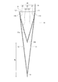
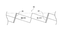
図4に示すように、伸張状態の本体部23は、非伸張状態の本体部23と比較して、懸架方向に伸びている。このときの本体部23では、懸架方向から面部11,12の厚み方向(非伸張状態における本体部23の厚み方向)へ片部31~36(図5および図6参照)が立ち上がり、立ち上がった片部31~36によって立体状の緩衝セル40が形成される。言い換えれば、一つの切れ込み部23aに対して周囲に配置された片部31~36が立ち上がることで、一つの緩衝セル40が出現する。
図4に示すように、伸張状態の本体部23は、非伸張状態の本体部23と比較して、懸架方向に伸びている。このときの本体部23では、懸架方向から面部11,12の厚み方向(非伸張状態における本体部23の厚み方向)へ片部31~36(図5および図6参照)が立ち上がり、立ち上がった片部31~36によって立体状の緩衝セル40が形成される。言い換えれば、一つの切れ込み部23aに対して周囲に配置された片部31~36が立ち上がることで、一つの緩衝セル40が出現する。
詳細に言えば、図5に示すように、第一片部31に対応する第一壁部41,第二片部32に対応する第二壁部42,第三片部33に対応する第三壁部43,第四片部34に対応する第四壁部44,第五片部35に対応する第五壁部45および第六片部36に対応する第六壁部46が、六角筒の各側壁をなすように緩衝セル40において立設される。
なお、本体部23が破損しない範囲で幾何学的に最も伸張した状態(以下「最大伸張状態」という)では、第一壁部41および第四壁部44が同一平面に沿うとともに、第三壁部43および第六壁部46が他の同一平面に沿って第一壁部41および第四壁部44と対向する。そのため、最大伸張状態の緩衝セル40では、四角筒の各側壁をなすように壁部41~46が立設される。
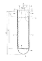
また、図4に示すように、伸張状態の緩衝部20は、本体袋10の底部13と非接触に設けられる。
具体的には、最大伸張状態の緩衝部20において最も下方に位置する折線部230と本体袋10の底部13とが接触しないように設けられる。言い換えれば、緩衝部20のうち貼付端部21,22の上端21a,22aと本体袋10の底部13との間の上下寸法を「M1」とし、上端21a,22aと最大伸張状態の緩衝部20における折線部230との間の上下寸法を「M2」とすれば、不等式2「M1>M2」が満たされる。
具体的には、最大伸張状態の緩衝部20において最も下方に位置する折線部230と本体袋10の底部13とが接触しないように設けられる。言い換えれば、緩衝部20のうち貼付端部21,22の上端21a,22aと本体袋10の底部13との間の上下寸法を「M1」とし、上端21a,22aと最大伸張状態の緩衝部20における折線部230との間の上下寸法を「M2」とすれば、不等式2「M1>M2」が満たされる。
さらに、この不等式2を満たしたうえで「M2」をできるだけ大きく設定して「M1」に近づけることが好ましい。
逆に言えば、図2に示すように、最大伸張状態の緩衝部20が本体袋10の底部13と接触しないように、未伸張状態の緩衝部20における折線部230が本体袋10の底部13に対して予め所定寸法「M3」だけ上方に設けられている。すなわち、緩衝部20は、伸び代を見越して短く形成されている。
逆に言えば、図2に示すように、最大伸張状態の緩衝部20が本体袋10の底部13と接触しないように、未伸張状態の緩衝部20における折線部230が本体袋10の底部13に対して予め所定寸法「M3」だけ上方に設けられている。すなわち、緩衝部20は、伸び代を見越して短く形成されている。
つづいて、図4を参照して、上記の非接触構造を実現するための緩衝部20の寸法の設定例を述べる。
緩衝部20におけるパターンP1,P2の行数を「N」とし、貼付端部21,22の上下寸法を「M4」とすれば、近似式3「M2-M4≒(L1-L2)×(N/4)」が成立する。
この近似式3の左辺は、最大伸張状態における第一本体部231または第二本体部232の上下寸法を表している。
一方、近似式3の右辺のうち(L1-L2)は、最大伸張状態における緩衝セル40一つあたりの懸架方向寸法、即ち、第一壁部41および第四壁部44の懸架方向の寸法を表している。
緩衝部20におけるパターンP1,P2の行数を「N」とし、貼付端部21,22の上下寸法を「M4」とすれば、近似式3「M2-M4≒(L1-L2)×(N/4)」が成立する。
この近似式3の左辺は、最大伸張状態における第一本体部231または第二本体部232の上下寸法を表している。
一方、近似式3の右辺のうち(L1-L2)は、最大伸張状態における緩衝セル40一つあたりの懸架方向寸法、即ち、第一壁部41および第四壁部44の懸架方向の寸法を表している。
また、本体部23において緩衝セル40が懸架方向に並ぶ数がパターンP1,P2の行数の半数(N/2)であることから、近似式3の右辺のうち(N/4)は、第一本体部231または第二本体部232において緩衝セル40が懸架方向に並ぶ数を表している。
ここで、幅方向に延びる第二壁部42および第五壁部45の懸架方向寸法を無視すれば、第一本体部231または第二本体部232において緩衝セル40が懸架方向に並ぶ数(N/4)を、最大伸張状態における緩衝セル40一つあたりの懸架方向寸法(L1-L2)に乗算した値(近似式3の右辺)は、第一本体部231または第二本体部232の最大伸張状態における上下寸法に近似するものと言える。
ここで、幅方向に延びる第二壁部42および第五壁部45の懸架方向寸法を無視すれば、第一本体部231または第二本体部232において緩衝セル40が懸架方向に並ぶ数(N/4)を、最大伸張状態における緩衝セル40一つあたりの懸架方向寸法(L1-L2)に乗算した値(近似式3の右辺)は、第一本体部231または第二本体部232の最大伸張状態における上下寸法に近似するものと言える。
そのため、切れ込み部23aあるいは非切れ込み部23bの幅方向寸法L1,L2やパターンP1,P2の行数、貼付端部21,22の上下寸法M4といった近似式3における各項に対応するパラメータを適宜設定することで、上記の非接触構造を設計することができる。
そのほか、緩衝部20の幅方向寸法は、面部11,12の幅方向寸法よりもやや小さく設けられている。
そのほか、緩衝部20の幅方向寸法は、面部11,12の幅方向寸法よりもやや小さく設けられている。
[2.包装袋の使用手順]
つぎに、包装袋の使用方法を説明する。
図1および図2に示すように、はじめにフラップ19を開いて開口9を開放し、本体袋10を開封する。
つぎに、包装袋の使用方法を説明する。
図1および図2に示すように、はじめにフラップ19を開いて開口9を開放し、本体袋10を開封する。
それから、包装袋に物品1を入れて、緩衝部20の本体部23に物品1を載置または挿入する。このとき、図4に示すように、緩衝部20の本体部23が懸架方向に伸びることで、面部11,12の厚み方向へ切れ込み部23aが立ち上がり、図5および図6に示すように、本体部23に緩衝セル40が出現する。
そして、本体袋10における第二面部12の上端縁部120にフラップ19を貼り付けて、包装袋を封緘する。このとき、物品1が緩衝セル40で囲まれる。
そして、本体袋10における第二面部12の上端縁部120にフラップ19を貼り付けて、包装袋を封緘する。このとき、物品1が緩衝セル40で囲まれる。
[3.作用および効果]
本実施形態の包装袋は、上述のように構成されるため、以下のような作用および効果を得ることができる。
(1)包装袋に物品1を入れて緩衝部20の本体部23に載せることで、未伸張状態ではシート状の本体部23が伸び、伸張状態となった本体部23には、切れ込み部23aのそれぞれに対応する立体状の緩衝セル40が出現する。本体袋10の内部に出現した緩衝セル40で物品1が囲まれることにより、物品1の保護性を確保することができ、包装袋に緩衝性を持たせることができる。
そのうえ、未伸張状態の本体部23がシート状であることから、エアクッションやフォーミングクッション,片面段ボールといった緩衝用の変形代が設けられた緩衝材が用いられた包装袋と比較して、未使用時の包装袋の嵩張りを抑えることができる。
本実施形態の包装袋は、上述のように構成されるため、以下のような作用および効果を得ることができる。
(1)包装袋に物品1を入れて緩衝部20の本体部23に載せることで、未伸張状態ではシート状の本体部23が伸び、伸張状態となった本体部23には、切れ込み部23aのそれぞれに対応する立体状の緩衝セル40が出現する。本体袋10の内部に出現した緩衝セル40で物品1が囲まれることにより、物品1の保護性を確保することができ、包装袋に緩衝性を持たせることができる。
そのうえ、未伸張状態の本体部23がシート状であることから、エアクッションやフォーミングクッション,片面段ボールといった緩衝用の変形代が設けられた緩衝材が用いられた包装袋と比較して、未使用時の包装袋の嵩張りを抑えることができる。
そのほか、従来の包装袋において本体袋とは別に緩衝材を設ける場合には、本体袋に対して緩衝材を固定するために、緩衝材の全体を本体袋に貼り付ける必要がある。これに対して、本包装袋では緩衝部20が懸架されているため、緩衝部20の一部を本体袋10に貼り付ければよく、接着材や粘着材の使用量を低減させることができる。
また、緩衝部20は、本体袋10の内部で伸びることによって緩衝機能を発揮することから、伸び代を見越して短く形成されている。そのため、平面状の材料シートを波打たせる加工(フルート加工)を施して製造される片面段ボールシートが緩衝材に用いられる包装袋と比較して、緩衝材の量あるいは重さを抑えることができる。
また、緩衝部20は、本体袋10の内部で伸びることによって緩衝機能を発揮することから、伸び代を見越して短く形成されている。そのため、平面状の材料シートを波打たせる加工(フルート加工)を施して製造される片面段ボールシートが緩衝材に用いられる包装袋と比較して、緩衝材の量あるいは重さを抑えることができる。
(2)伸張状態の緩衝部20が底部13と非接触に設けられているため、包装袋に入れられる物品1と本体袋10の底部13との接触(底付き)が抑えられ、物品1の保護性を高めることができる。
(3)緩衝部20の貼付端部21,22は、本体袋10の上端縁部110,120における内面111,121に貼り付けられる。そのため、貼付端部と本体部との間で緩衝部が山折りされて上端縁部110,120の外面に貼付端部が貼り付けられる包装袋に比較して、緩衝部20の材料の量や重さを抑えることができる。
そのほか、内面111,121に貼付端部21,22が貼り付けられることで、本体袋10のフラップ19と緩衝部20との干渉が防止され、開口9を円滑に開閉することができる。
そのほか、内面111,121に貼付端部21,22が貼り付けられることで、本体袋10のフラップ19と緩衝部20との干渉が防止され、開口9を円滑に開閉することができる。
(4)第一面部11,第二面部12およびフラップ19から構成される本体袋10ならびに緩衝部20が同一の材料から形成されるため、使用後の包装袋の処理性を向上させることができる。たとえば、包装袋を再生利用(リサイクル)あるいは廃棄する際に、材料ごとに分別する必要がなく、処理作業性を向上させることができる。本体袋10および緩衝部20が紙製であれば、古紙回収や可燃ごみに使用後の包装袋をそのまま出すことができる。
(5)緩衝部20が二つ折りにされた状態で懸架されるため、たとえば緩衝部が三つ以上に折られた状態で懸架される包装袋と比較して、未使用時の包装袋の厚みを抑えることができる。
具体的には、未使用時の包装袋において本体部23が設けられる箇所では、第一面部11,第一本体部231,第二本体部232,第二面部12の順に四つのシート片が積層される。これに対して、三つ以上に折られた緩衝部では、三つ以上の本体部が折り畳まれ、五つ以上のシート片が積層される。したがって、折り畳まれた本体部23の厚みが抑えられることで、包装袋の嵩張りを抑えることができる。
具体的には、未使用時の包装袋において本体部23が設けられる箇所では、第一面部11,第一本体部231,第二本体部232,第二面部12の順に四つのシート片が積層される。これに対して、三つ以上に折られた緩衝部では、三つ以上の本体部が折り畳まれ、五つ以上のシート片が積層される。したがって、折り畳まれた本体部23の厚みが抑えられることで、包装袋の嵩張りを抑えることができる。
[4.その他]
最後に、本実施形態のその他の変形例について述べる。
たとえば、切れ込み部および非切れ込み部は、幅方向に延びる配向に限らず、少なくとも懸架方向に対して交差する方向に延びていればよい。このような配向により、緩衝部を懸架方向に伸張させることができる。
そのほか、本体袋には、フラップ19が設けられたマチ無しの封筒型に限らず、たとえば角底袋,ガセット袋,スタンディングパウチといったさまざまな型式の袋を用いることができ、マチ付きの袋やフラップ無しの袋を用いてもよい。
フラップ無しの袋が本体袋に用いられる場合には、貼付端部と本体部との間で緩衝部が山折りされて、上端縁部110,120の外面に貼付端部が貼り付けられてもよい。このときには、面部11,12に引っ掛かるようにして緩衝部が懸架されることで、本体袋に対して確実に緩衝部を取り付けることができ、緩衝部の耐荷重を高めることができる。
最後に、本実施形態のその他の変形例について述べる。
たとえば、切れ込み部および非切れ込み部は、幅方向に延びる配向に限らず、少なくとも懸架方向に対して交差する方向に延びていればよい。このような配向により、緩衝部を懸架方向に伸張させることができる。
そのほか、本体袋には、フラップ19が設けられたマチ無しの封筒型に限らず、たとえば角底袋,ガセット袋,スタンディングパウチといったさまざまな型式の袋を用いることができ、マチ付きの袋やフラップ無しの袋を用いてもよい。
フラップ無しの袋が本体袋に用いられる場合には、貼付端部と本体部との間で緩衝部が山折りされて、上端縁部110,120の外面に貼付端部が貼り付けられてもよい。このときには、面部11,12に引っ掛かるようにして緩衝部が懸架されることで、本体袋に対して確実に緩衝部を取り付けることができ、緩衝部の耐荷重を高めることができる。
図9に示した変形例では、緩衝部20の第一貼付端部21は、本体袋10のフラップ19と重なる部分を有する。この変形例では封緘時に第一貼付端部21がフラップ19とともに折り曲げられて第二面部を外側から覆うため、内包物を懸架するための強度が高められる。
以下に実施例と比較例を挙げて本発明の特徴をさらに具体的に説明するが、本発明の範囲は以下に示す具体例により限定的に解釈されるべきものではない。
<包装袋サンプルの作製>
図8に示す包装袋サンプルを作製した。第一面部(第二面部)の上下寸法は300mm、幅方向寸法は240mmとした。緩衝部は二つ折り未伸張の状態での上下寸法120mm、幅方向寸法は240mmとした。緩衝部は、面部の上端縁部に両面テープで貼り付けた。
また、第一面部および第二面部の材料、緩衝部の材料は表1に記載のものを使用して実施例および比較例の包装袋サンプルを作製した。
<包装袋サンプルの作製>
図8に示す包装袋サンプルを作製した。第一面部(第二面部)の上下寸法は300mm、幅方向寸法は240mmとした。緩衝部は二つ折り未伸張の状態での上下寸法120mm、幅方向寸法は240mmとした。緩衝部は、面部の上端縁部に両面テープで貼り付けた。
また、第一面部および第二面部の材料、緩衝部の材料は表1に記載のものを使用して実施例および比較例の包装袋サンプルを作製した。
<サンプルの評価>
実施例および比較例の包装袋サンプルの中に衝撃加速度計(製品名:G-menDR100、スリック社製)を挿入し封緘した後、JISZ0200の衝撃試験に記載の自由落下試験を行い、衝撃加速度の最大値を測定した。
試験結果を表1に示す。
実施例および比較例の包装袋サンプルの中に衝撃加速度計(製品名:G-menDR100、スリック社製)を挿入し封緘した後、JISZ0200の衝撃試験に記載の自由落下試験を行い、衝撃加速度の最大値を測定した。
試験結果を表1に示す。

上記表1の試験結果が示すとおり、実施例1~4は、比較例1~2に比べて衝撃加速度が小さく、衝撃吸収速度に優れるものであった。
1 物品
9 開口
10 本体袋
11 第一面部
110 上端縁部(第一端縁部)
111 内面
12 第二面部
120 上端縁部(第二端縁部)
121 内面
13 底部
14,15 側部
19 フラップ
20 緩衝部
21 第一貼付端部
21a 上端
22 第二貼付端部
22a 上端
23 本体部
230 折線部
231 第一本体部
232 第二本体部
23a,23a′ 切れ込み部
23b,23b′ 非切れ込み部
31,32,33,34,35,36 片部
40 緩衝セル
41,42,43,44,45,46 壁部
Ca,Ca′ 切れ込み部23a,23a′の幅方向中心
Cb,Cb′ 非切れ込み部の23b,23b′幅方向中心
L1 切れ込み部23a,23a′の幅方向寸法
L2 非切れ込み部23b,23b′の幅方向寸法
M1 上端21a,22aと本体袋20の底部13との間の上下寸法
M2 上端21a,22aと最大伸張状態の折線部230との間の上下寸法
M3 底部13に対する未伸張状態の折線部230の上下寸法
M4 貼付端部21、22の上下寸法
N パターンP1,P2の行数
P1 第一パターン
P2 第二パターン
9 開口
10 本体袋
11 第一面部
110 上端縁部(第一端縁部)
111 内面
12 第二面部
120 上端縁部(第二端縁部)
121 内面
13 底部
14,15 側部
19 フラップ
20 緩衝部
21 第一貼付端部
21a 上端
22 第二貼付端部
22a 上端
23 本体部
230 折線部
231 第一本体部
232 第二本体部
23a,23a′ 切れ込み部
23b,23b′ 非切れ込み部
31,32,33,34,35,36 片部
40 緩衝セル
41,42,43,44,45,46 壁部
Ca,Ca′ 切れ込み部23a,23a′の幅方向中心
Cb,Cb′ 非切れ込み部の23b,23b′幅方向中心
L1 切れ込み部23a,23a′の幅方向寸法
L2 非切れ込み部23b,23b′の幅方向寸法
M1 上端21a,22aと本体袋20の底部13との間の上下寸法
M2 上端21a,22aと最大伸張状態の折線部230との間の上下寸法
M3 底部13に対する未伸張状態の折線部230の上下寸法
M4 貼付端部21、22の上下寸法
N パターンP1,P2の行数
P1 第一パターン
P2 第二パターン
Claims (5)
- 開口の一側に配置された第一端縁部を有する第一面部と、
前記開口の他側に配置された第二端縁部を有し、前記第一面部と対向する第二面部と、
前記第一端縁部と前記第二端縁部との間に懸架され、懸架方向に交差する方向に延びる複数の切れ込み部が千鳥状に設けられた伸張可能なシート状の緩衝部とを備えた包装袋であって、
前記第一面部および前記第二面部を形成するシート材料の坪量に対する前記緩衝部を形成するシート材料の坪量の割合が55~80%である包装袋。 - 前記緩衝部は、伸張した状態で底部と非接触に設けられた
ことを特徴とする請求項1に記載された包装袋。 - 前記緩衝部は、前記第一端縁部または前記第二端縁部の内面に貼り付けられる貼付端部を有する
ことを特徴とする請求項1または2に記載された包装袋。 - 前記第一面部および前記第二面部ならびに前記緩衝部は、同一の材料から形成された
ことを特徴とする請求項1~3の何れか1項に記載された包装袋。 - 前記緩衝部は、前記第一端縁部と前記第二端縁部との間で二つ折りにされた状態で懸架された
ことを特徴とする請求項1~4の何れか1項に記載された包装袋。
Priority Applications (3)
| Application Number | Priority Date | Filing Date | Title |
|---|---|---|---|
| US17/293,098 US20220002059A1 (en) | 2018-11-13 | 2019-11-12 | Packaging bag |
| CN201980074465.2A CN112996735A (zh) | 2018-11-13 | 2019-11-12 | 包装袋 |
| JP2020556125A JP7268687B2 (ja) | 2018-11-13 | 2019-11-12 | 包装袋 |
Applications Claiming Priority (2)
| Application Number | Priority Date | Filing Date | Title |
|---|---|---|---|
| JP2018212651 | 2018-11-13 | ||
| JP2018-212651 | 2018-11-13 |
Publications (1)
| Publication Number | Publication Date |
|---|---|
| WO2020100915A1 true WO2020100915A1 (ja) | 2020-05-22 |
Family
ID=70731376
Family Applications (1)
| Application Number | Title | Priority Date | Filing Date |
|---|---|---|---|
| PCT/JP2019/044411 Ceased WO2020100915A1 (ja) | 2018-11-13 | 2019-11-12 | 包装袋 |
Country Status (4)
| Country | Link |
|---|---|
| US (1) | US20220002059A1 (ja) |
| JP (1) | JP7268687B2 (ja) |
| CN (1) | CN112996735A (ja) |
| WO (1) | WO2020100915A1 (ja) |
Cited By (3)
| Publication number | Priority date | Publication date | Assignee | Title |
|---|---|---|---|---|
| CN112373949A (zh) * | 2020-11-14 | 2021-02-19 | 东莞市茶山捷锐模具加工厂 | 一种蜂窝式缓冲包装袋 |
| CN115943109A (zh) * | 2020-07-27 | 2023-04-07 | 朗派公司 | 可扩展带垫邮包 |
| WO2025222921A1 (zh) * | 2024-04-22 | 2025-10-30 | 惠州市成泰昌新材料科技有限公司 | 一种缓冲包装袋在线包装物品的方法及设备 |
Families Citing this family (8)
| Publication number | Priority date | Publication date | Assignee | Title |
|---|---|---|---|---|
| US11440305B2 (en) | 2017-06-26 | 2022-09-13 | David Paul Goodrich | Embossed paper in combination with paper cushioning for shipping envelopes |
| US11401090B2 (en) | 2017-06-26 | 2022-08-02 | David Paul Goodrich | Expanded slit sheet cushioning products with novel slit pattern and paper properties |
| US11702261B2 (en) | 2017-06-26 | 2023-07-18 | David Paul Goodrich | Expanded slit sheet cushioning products with novel reduced dimension slit patterns |
| US12017820B2 (en) * | 2019-03-29 | 2024-06-25 | Beta (Shenzhen) Package Products Co., Ltd | Cushion pad and packaging bag thereof |
| US12605923B2 (en) | 2020-11-09 | 2026-04-21 | Iow, Llc | Packaging material having expandable layers |
| US11931985B2 (en) * | 2020-11-09 | 2024-03-19 | Iow, Llc | Packaging material with expanding layer and packaging enclosure formed therewith |
| WO2024035824A1 (en) * | 2022-08-10 | 2024-02-15 | David Paul Goodrich | Improved paper cushioned shipping envelopes and methods of making the same |
| KR20250093605A (ko) * | 2022-08-22 | 2025-06-24 | 베타 (썬전) 패키지 프로덕츠 컴퍼니 리미티드 | 완충 패드 및 포장백 |
Citations (2)
| Publication number | Priority date | Publication date | Assignee | Title |
|---|---|---|---|---|
| JP2007238142A (ja) * | 2006-03-09 | 2007-09-20 | Kuniharu Nagahashi | 紙製封筒 |
| JP2017193373A (ja) * | 2016-04-14 | 2017-10-26 | 王子ホールディングス株式会社 | 包装体 |
Family Cites Families (10)
| Publication number | Priority date | Publication date | Assignee | Title |
|---|---|---|---|---|
| JPH07315440A (ja) * | 1994-05-28 | 1995-12-05 | Kawakami Sangyo Kk | 斜柱小片紙質緩衝材 |
| US6371643B2 (en) * | 1999-06-02 | 2002-04-16 | S. C. Johnson Home Storage, Inc. | Multi-Layered freezer storage bag |
| JP2004244024A (ja) | 2003-02-10 | 2004-09-02 | Sankei:Kk | 商品等の輸送容器 |
| JP2008018979A (ja) * | 2006-07-13 | 2008-01-31 | Toshiba Elevator Co Ltd | 空中梱包具 |
| ITRM20100114U1 (it) * | 2010-07-01 | 2012-01-02 | Daniela Fileni | Culla per trasportare e spedire senza tema di rottura oggetti fragili e preziosi |
| JP3165722U (ja) | 2010-11-11 | 2011-02-03 | 実 横内 | 紙製袋 |
| WO2014032059A1 (en) * | 2012-08-20 | 2014-02-27 | Steven Michael Stack | Package article and method |
| JP5556949B1 (ja) * | 2013-11-11 | 2014-07-23 | 住友ベークライト株式会社 | 青果物用包装袋および青果物包装体 |
| TWM489153U (en) | 2014-03-19 | 2014-11-01 | Chih-Hao Feng | Shock absorbing collision avoidance box |
| JP6690630B2 (ja) * | 2017-12-04 | 2020-04-28 | 王子ホールディングス株式会社 | 包装袋の製造方法 |
-
2019
- 2019-11-12 JP JP2020556125A patent/JP7268687B2/ja active Active
- 2019-11-12 CN CN201980074465.2A patent/CN112996735A/zh active Pending
- 2019-11-12 WO PCT/JP2019/044411 patent/WO2020100915A1/ja not_active Ceased
- 2019-11-12 US US17/293,098 patent/US20220002059A1/en not_active Abandoned
Patent Citations (3)
| Publication number | Priority date | Publication date | Assignee | Title |
|---|---|---|---|---|
| JP2007238142A (ja) * | 2006-03-09 | 2007-09-20 | Kuniharu Nagahashi | 紙製封筒 |
| JP2017193373A (ja) * | 2016-04-14 | 2017-10-26 | 王子ホールディングス株式会社 | 包装体 |
| JP2017193376A (ja) * | 2016-04-14 | 2017-10-26 | 王子ホールディングス株式会社 | 包装袋 |
Cited By (3)
| Publication number | Priority date | Publication date | Assignee | Title |
|---|---|---|---|---|
| CN115943109A (zh) * | 2020-07-27 | 2023-04-07 | 朗派公司 | 可扩展带垫邮包 |
| CN112373949A (zh) * | 2020-11-14 | 2021-02-19 | 东莞市茶山捷锐模具加工厂 | 一种蜂窝式缓冲包装袋 |
| WO2025222921A1 (zh) * | 2024-04-22 | 2025-10-30 | 惠州市成泰昌新材料科技有限公司 | 一种缓冲包装袋在线包装物品的方法及设备 |
Also Published As
| Publication number | Publication date |
|---|---|
| JPWO2020100915A1 (ja) | 2021-09-30 |
| CN112996735A (zh) | 2021-06-18 |
| US20220002059A1 (en) | 2022-01-06 |
| JP7268687B2 (ja) | 2023-05-08 |
Similar Documents
| Publication | Publication Date | Title |
|---|---|---|
| WO2020100915A1 (ja) | 包装袋 | |
| JP6834736B2 (ja) | 包装袋 | |
| JP7439967B2 (ja) | 包装袋 | |
| JP7825372B2 (ja) | 包装容器及びその製造方法 | |
| JP2019099223A (ja) | 包装袋 | |
| JP7127483B2 (ja) | 内装ユニットおよび包装袋 | |
| JP7392891B2 (ja) | 包装袋を用いた物品の収納方法 | |
| JPWO2012128253A1 (ja) | 緩衝機能を有する包装用箱 | |
| JP6926801B2 (ja) | 包装袋の製造方法 | |
| ES3050736T3 (en) | Expandable padded mailer and method of manufacturing the same | |
| US3501084A (en) | Packaging structures | |
| JP7424224B2 (ja) | 包装袋 | |
| ES3041490T3 (en) | Reinforced package | |
| JP2019031303A (ja) | 包装袋 | |
| JP7087943B2 (ja) | 包装袋 | |
| JP3248729U (ja) | 包装袋 | |
| JP3249463U (ja) | 包装袋 | |
| CN220097136U (zh) | 一种带有蜂窝内衬的信封纸袋 | |
| JP2026070743A (ja) | 包装袋の製造方法 | |
| JP2025134499A (ja) | 包装袋 | |
| JP2026032813A (ja) | 包装袋の製造方法 | |
| JP3241980U (ja) | 包装袋 | |
| JP7424225B2 (ja) | 包装袋 | |
| JP7380192B2 (ja) | 包装袋および包装袋用シート | |
| JP7375531B2 (ja) | 包装袋および包装袋用シート |
Legal Events
| Date | Code | Title | Description |
|---|---|---|---|
| 121 | Ep: the epo has been informed by wipo that ep was designated in this application |
Ref document number: 19884735 Country of ref document: EP Kind code of ref document: A1 |
|
| ENP | Entry into the national phase |
Ref document number: 2020556125 Country of ref document: JP Kind code of ref document: A |
|
| NENP | Non-entry into the national phase |
Ref country code: DE |
|
| 122 | Ep: pct application non-entry in european phase |
Ref document number: 19884735 Country of ref document: EP Kind code of ref document: A1 |