WO2020100846A1 - 熱管理システム - Google Patents
熱管理システム Download PDFInfo
- Publication number
- WO2020100846A1 WO2020100846A1 PCT/JP2019/044218 JP2019044218W WO2020100846A1 WO 2020100846 A1 WO2020100846 A1 WO 2020100846A1 JP 2019044218 W JP2019044218 W JP 2019044218W WO 2020100846 A1 WO2020100846 A1 WO 2020100846A1
- Authority
- WO
- WIPO (PCT)
- Prior art keywords
- heat
- heat exchanger
- external device
- management system
- medium
- Prior art date
- Legal status (The legal status is an assumption and is not a legal conclusion. Google has not performed a legal analysis and makes no representation as to the accuracy of the status listed.)
- Ceased
Links
Images




Classifications
-
- F—MECHANICAL ENGINEERING; LIGHTING; HEATING; WEAPONS; BLASTING
- F28—HEAT EXCHANGE IN GENERAL
- F28D—HEAT-EXCHANGE APPARATUS, NOT PROVIDED FOR IN ANOTHER SUBCLASS, IN WHICH THE HEAT-EXCHANGE MEDIA DO NOT COME INTO DIRECT CONTACT
- F28D20/00—Heat storage plants or apparatus in general; Regenerative heat-exchange apparatus not covered by groups F28D17/00 or F28D19/00
- F28D20/02—Heat storage plants or apparatus in general; Regenerative heat-exchange apparatus not covered by groups F28D17/00 or F28D19/00 using latent heat
- F28D20/021—Heat storage plants or apparatus in general; Regenerative heat-exchange apparatus not covered by groups F28D17/00 or F28D19/00 using latent heat the latent heat storage material and the heat-exchanging means being enclosed in one container
-
- B—PERFORMING OPERATIONS; TRANSPORTING
- B60—VEHICLES IN GENERAL
- B60H—ARRANGEMENTS OF HEATING, COOLING, VENTILATING OR OTHER AIR-TREATING DEVICES SPECIALLY ADAPTED FOR PASSENGER OR GOODS SPACES OF VEHICLES
- B60H1/00—Heating, cooling or ventilating devices
- B60H1/00271—HVAC devices specially adapted for particular vehicle parts or components and being connected to the vehicle HVAC unit
-
- B—PERFORMING OPERATIONS; TRANSPORTING
- B60—VEHICLES IN GENERAL
- B60H—ARRANGEMENTS OF HEATING, COOLING, VENTILATING OR OTHER AIR-TREATING DEVICES SPECIALLY ADAPTED FOR PASSENGER OR GOODS SPACES OF VEHICLES
- B60H1/00—Heating, cooling or ventilating devices
- B60H1/00357—Air-conditioning arrangements specially adapted for particular vehicles
- B60H1/00385—Air-conditioning arrangements specially adapted for particular vehicles for vehicles having an electrical drive, e.g. hybrid or fuel cell
-
- B—PERFORMING OPERATIONS; TRANSPORTING
- B60—VEHICLES IN GENERAL
- B60H—ARRANGEMENTS OF HEATING, COOLING, VENTILATING OR OTHER AIR-TREATING DEVICES SPECIALLY ADAPTED FOR PASSENGER OR GOODS SPACES OF VEHICLES
- B60H1/00—Heating, cooling or ventilating devices
- B60H1/00357—Air-conditioning arrangements specially adapted for particular vehicles
- B60H1/00385—Air-conditioning arrangements specially adapted for particular vehicles for vehicles having an electrical drive, e.g. hybrid or fuel cell
- B60H1/00392—Air-conditioning arrangements specially adapted for particular vehicles for vehicles having an electrical drive, e.g. hybrid or fuel cell for electric vehicles having only electric drive means
-
- B—PERFORMING OPERATIONS; TRANSPORTING
- B60—VEHICLES IN GENERAL
- B60H—ARRANGEMENTS OF HEATING, COOLING, VENTILATING OR OTHER AIR-TREATING DEVICES SPECIALLY ADAPTED FOR PASSENGER OR GOODS SPACES OF VEHICLES
- B60H1/00—Heating, cooling or ventilating devices
- B60H1/00642—Control systems or circuits; Control members or indication devices for heating, cooling or ventilating devices
- B60H1/00814—Control systems or circuits characterised by their output, for controlling particular components of the heating, cooling or ventilating installation
- B60H1/00878—Control systems or circuits characterised by their output, for controlling particular components of the heating, cooling or ventilating installation the components being temperature regulating devices
- B60H1/00899—Controlling the flow of liquid in a heat pump system
- B60H1/00921—Controlling the flow of liquid in a heat pump system where the flow direction of the refrigerant does not change and there is an extra subcondenser, e.g. in an air duct
-
- B—PERFORMING OPERATIONS; TRANSPORTING
- B60—VEHICLES IN GENERAL
- B60H—ARRANGEMENTS OF HEATING, COOLING, VENTILATING OR OTHER AIR-TREATING DEVICES SPECIALLY ADAPTED FOR PASSENGER OR GOODS SPACES OF VEHICLES
- B60H1/00—Heating, cooling or ventilating devices
- B60H1/02—Heating, cooling or ventilating devices the heat being derived from the propulsion plant
- B60H1/14—Heating, cooling or ventilating devices the heat being derived from the propulsion plant other than from cooling liquid of the plant
- B60H1/143—Heating, cooling or ventilating devices the heat being derived from the propulsion plant other than from cooling liquid of the plant the heat being derived from cooling an electric component, e.g. electric motors, electric circuits, fuel cells or batteries
-
- B—PERFORMING OPERATIONS; TRANSPORTING
- B60—VEHICLES IN GENERAL
- B60H—ARRANGEMENTS OF HEATING, COOLING, VENTILATING OR OTHER AIR-TREATING DEVICES SPECIALLY ADAPTED FOR PASSENGER OR GOODS SPACES OF VEHICLES
- B60H1/00—Heating, cooling or ventilating devices
- B60H1/32—Cooling devices
- B60H1/3204—Cooling devices using compression
- B60H1/3228—Cooling devices using compression characterised by refrigerant circuit configurations
- B60H1/32281—Cooling devices using compression characterised by refrigerant circuit configurations comprising a single secondary circuit, e.g. at evaporator or condenser side
-
- B—PERFORMING OPERATIONS; TRANSPORTING
- B60—VEHICLES IN GENERAL
- B60H—ARRANGEMENTS OF HEATING, COOLING, VENTILATING OR OTHER AIR-TREATING DEVICES SPECIALLY ADAPTED FOR PASSENGER OR GOODS SPACES OF VEHICLES
- B60H1/00—Heating, cooling or ventilating devices
- B60H1/32—Cooling devices
- B60H1/3204—Cooling devices using compression
- B60H1/323—Cooling devices using compression characterised by comprising auxiliary or multiple systems, e.g. plurality of evaporators, or by involving auxiliary cooling devices
-
- F—MECHANICAL ENGINEERING; LIGHTING; HEATING; WEAPONS; BLASTING
- F25—REFRIGERATION OR COOLING; COMBINED HEATING AND REFRIGERATION SYSTEMS; HEAT PUMP SYSTEMS; MANUFACTURE OR STORAGE OF ICE; LIQUEFACTION SOLIDIFICATION OF GASES
- F25B—REFRIGERATION MACHINES, PLANTS OR SYSTEMS; COMBINED HEATING AND REFRIGERATION SYSTEMS; HEAT PUMP SYSTEMS
- F25B1/00—Compression machines, plants or systems with non-reversible cycle
-
- F—MECHANICAL ENGINEERING; LIGHTING; HEATING; WEAPONS; BLASTING
- F28—HEAT EXCHANGE IN GENERAL
- F28D—HEAT-EXCHANGE APPARATUS, NOT PROVIDED FOR IN ANOTHER SUBCLASS, IN WHICH THE HEAT-EXCHANGE MEDIA DO NOT COME INTO DIRECT CONTACT
- F28D20/00—Heat storage plants or apparatus in general; Regenerative heat-exchange apparatus not covered by groups F28D17/00 or F28D19/00
-
- F—MECHANICAL ENGINEERING; LIGHTING; HEATING; WEAPONS; BLASTING
- F28—HEAT EXCHANGE IN GENERAL
- F28D—HEAT-EXCHANGE APPARATUS, NOT PROVIDED FOR IN ANOTHER SUBCLASS, IN WHICH THE HEAT-EXCHANGE MEDIA DO NOT COME INTO DIRECT CONTACT
- F28D9/00—Heat-exchange apparatus having stationary plate-like or laminated conduit assemblies for both heat-exchange media, the media being in contact with different sides of a conduit wall
- F28D9/0031—Heat-exchange apparatus having stationary plate-like or laminated conduit assemblies for both heat-exchange media, the media being in contact with different sides of a conduit wall the conduits for one heat-exchange medium being formed by paired plates touching each other
- F28D9/0037—Heat-exchange apparatus having stationary plate-like or laminated conduit assemblies for both heat-exchange media, the media being in contact with different sides of a conduit wall the conduits for one heat-exchange medium being formed by paired plates touching each other the conduits for the other heat-exchange medium also being formed by paired plates touching each other
-
- B—PERFORMING OPERATIONS; TRANSPORTING
- B60—VEHICLES IN GENERAL
- B60H—ARRANGEMENTS OF HEATING, COOLING, VENTILATING OR OTHER AIR-TREATING DEVICES SPECIALLY ADAPTED FOR PASSENGER OR GOODS SPACES OF VEHICLES
- B60H1/00—Heating, cooling or ventilating devices
- B60H1/00007—Combined heating, ventilating, or cooling devices
- B60H1/00021—Air flow details of HVAC devices
- B60H2001/00114—Heating or cooling details
- B60H2001/00128—Electric heaters
-
- B—PERFORMING OPERATIONS; TRANSPORTING
- B60—VEHICLES IN GENERAL
- B60H—ARRANGEMENTS OF HEATING, COOLING, VENTILATING OR OTHER AIR-TREATING DEVICES SPECIALLY ADAPTED FOR PASSENGER OR GOODS SPACES OF VEHICLES
- B60H1/00—Heating, cooling or ventilating devices
- B60H1/00271—HVAC devices specially adapted for particular vehicle parts or components and being connected to the vehicle HVAC unit
- B60H2001/00307—Component temperature regulation using a liquid flow
-
- B—PERFORMING OPERATIONS; TRANSPORTING
- B60—VEHICLES IN GENERAL
- B60H—ARRANGEMENTS OF HEATING, COOLING, VENTILATING OR OTHER AIR-TREATING DEVICES SPECIALLY ADAPTED FOR PASSENGER OR GOODS SPACES OF VEHICLES
- B60H1/00—Heating, cooling or ventilating devices
- B60H1/00642—Control systems or circuits; Control members or indication devices for heating, cooling or ventilating devices
- B60H1/00814—Control systems or circuits characterised by their output, for controlling particular components of the heating, cooling or ventilating installation
- B60H1/00878—Control systems or circuits characterised by their output, for controlling particular components of the heating, cooling or ventilating installation the components being temperature regulating devices
- B60H2001/00949—Control systems or circuits characterised by their output, for controlling particular components of the heating, cooling or ventilating installation the components being temperature regulating devices comprising additional heating/cooling sources, e.g. second evaporator
-
- F—MECHANICAL ENGINEERING; LIGHTING; HEATING; WEAPONS; BLASTING
- F28—HEAT EXCHANGE IN GENERAL
- F28D—HEAT-EXCHANGE APPARATUS, NOT PROVIDED FOR IN ANOTHER SUBCLASS, IN WHICH THE HEAT-EXCHANGE MEDIA DO NOT COME INTO DIRECT CONTACT
- F28D20/00—Heat storage plants or apparatus in general; Regenerative heat-exchange apparatus not covered by groups F28D17/00 or F28D19/00
- F28D2020/006—Heat storage systems not otherwise provided for
-
- F—MECHANICAL ENGINEERING; LIGHTING; HEATING; WEAPONS; BLASTING
- F28—HEAT EXCHANGE IN GENERAL
- F28D—HEAT-EXCHANGE APPARATUS, NOT PROVIDED FOR IN ANOTHER SUBCLASS, IN WHICH THE HEAT-EXCHANGE MEDIA DO NOT COME INTO DIRECT CONTACT
- F28D20/00—Heat storage plants or apparatus in general; Regenerative heat-exchange apparatus not covered by groups F28D17/00 or F28D19/00
- F28D2020/0065—Details, e.g. particular heat storage tanks, auxiliary members within tanks
- F28D2020/0078—Heat exchanger arrangements
-
- Y—GENERAL TAGGING OF NEW TECHNOLOGICAL DEVELOPMENTS; GENERAL TAGGING OF CROSS-SECTIONAL TECHNOLOGIES SPANNING OVER SEVERAL SECTIONS OF THE IPC; TECHNICAL SUBJECTS COVERED BY FORMER USPC CROSS-REFERENCE ART COLLECTIONS [XRACs] AND DIGESTS
- Y02—TECHNOLOGIES OR APPLICATIONS FOR MITIGATION OR ADAPTATION AGAINST CLIMATE CHANGE
- Y02E—REDUCTION OF GREENHOUSE GAS [GHG] EMISSIONS, RELATED TO ENERGY GENERATION, TRANSMISSION OR DISTRIBUTION
- Y02E60/00—Enabling technologies; Technologies with a potential or indirect contribution to GHG emissions mitigation
- Y02E60/14—Thermal energy storage
Definitions
- the present invention relates to a heat management system.
- heat pump type air conditioner an air conditioner including a heat pump type refrigeration circuit
- the heat pump type air conditioner obtains heat necessary for air conditioning from the outside air by exchanging heat between the air outside the room and the heat medium (refrigerant), which is the object of air conditioning.
- the heat pump type air conditioner uses less energy for air conditioning, particularly for heating, as compared with the case of using an electric heater that heats air by using electric power, for example, a PTC (Positive Temperature Coefficient) heater. It is suppressed (for example, refer to Patent Documents 1 to 3).
- the heat pump type air conditioner as described above does not require a heat source to heat the air. Therefore, in the heat pump type air conditioner, a vehicle such as an electric vehicle or a fuel cell vehicle that does not have an internal combustion engine that can be used as a heat source during heating, or a hybrid vehicle or a plug-in hybrid vehicle is not always operating. It is useful as an air conditioner used in a vehicle.
- the heat pump type air conditioner uses the heat from the air as a heat source for heating in principle. Therefore, the conventional heat pump type air conditioner has a problem that it is difficult to sufficiently warm the indoor temperature when the temperature difference between the temperature of the heat medium and the outside air temperature is small or does not occur, such as during cold weather. It was happening.
- a heat pump is combined with an electric heater such as the above PTC heater, or a gas injection type heat pump is used.
- the present invention has been made in view of the above problems, and an object thereof is to provide a heat management system capable of suppressing energy consumption and improving heating performance.
- the heat management system is a heat management system that performs heat management in a room, and an outdoor heat exchanger that performs heat exchange between a heat medium and outdoor air, A compressor that compresses the heat medium that has been heat-exchanged by the outdoor heat exchanger, and an indoor heat exchanger that performs heat exchange between the heat medium compressed by the compressor and the indoor air.
- An external device heat exchanger that is provided between the outdoor heat exchanger and the compressor to exchange heat between the heat generated by an external device and the heat medium.
- the outdoor heat exchanger receives heat from the outdoor air and radiates the heat to the heat medium
- the external device heat exchanger receives heat from the external device and the The heat is radiated to a heat medium
- the compressor compresses and heats the heat medium received from the outdoor heat exchanger and the external device heat exchanger
- the indoor heat exchanger heats up by the compressor. The temperature of the air in the room is raised by the heat medium thus generated.
- the external device heat exchanger stores the heat generated by the external device and exchanges heat with the heat medium.
- the external device heat exchanger includes a heat dissipation unit that dissipates heat generated by the external device, a heat storage unit that stores heat dissipated by the heat dissipation unit, and the heat storage unit.
- a heat receiving unit that receives the heat accumulated by the unit into the heat medium.
- the external device heat exchanger includes an electric heating unit that heats the heat storage unit.
- the heat management system manages heat in a room such as a vehicle or a building.
- the heat management system will be described as an example of an air conditioner that is installed in an electric vehicle to perform air conditioning in the vehicle interior of the electric vehicle as a predetermined space that is the target of heat management. .
- FIG. 1 is a functional block diagram showing a schematic configuration of a thermal management system 1 according to the first embodiment of the present invention.
- the thermal management system 1 describes the basic configuration of the thermal management system according to the present invention.
- the heat management system 1 is an example of a heat pump type heating system that uses air heat outside the vehicle interior as a heat source in order to raise the temperature in the vehicle interior.
- a heat management system 1 performs heat exchange by an outdoor heat exchanger 2 that performs heat exchange between a heat medium and outdoor air, and an outdoor heat exchanger 2.
- a compressor 5 for compressing the heat medium that has been separated
- an indoor heat exchanger 6 that exchanges heat between the heat medium compressed by the compressor 5 and the indoor air
- an outdoor heat exchanger 2 and the compressor 5.
- an external device heat exchanger 3 for exchanging heat between the heat generated by the external device 40 and the heat medium.
- a heat medium circuit HM capable of circulating a heat medium is formed between the outdoor heat exchanger 2, the external equipment heat exchanger 3, the compressor 5, and the indoor heat exchanger 6.
- the heat medium may be the same as the one generally called a refrigerant in an ordinary air conditioner.
- the heat medium circuit HM is composed of flow paths HM11 to HM14.
- the flow path HM11 connects the outdoor heat exchanger 2 and the external device heat exchanger 3.
- the flow path HM12 connects between the external device heat exchanger 3 and the compressor 5.
- the flow path HM13 connects between the compressor 5 and the indoor heat exchanger 6.
- the flow path HM14 connects between the indoor heat exchanger 6 and the outdoor heat exchanger 2.
- the heat management system 1 constitutes a heat pump type refrigeration circuit by connecting the outdoor heat exchanger 2, the external device heat exchanger 3, the compressor 5, and the indoor heat exchanger 6 in order by the heat medium circuit HM. is doing.
- the external device 40 is various heat sources provided outside the heat management system 1, such as a power motor for an electric vehicle or an inverter used for controlling the motor.
- a power motor for an electric vehicle or an inverter used for controlling the motor.
- an LLC for cooling the motor, the inverter, or the external device 40 such as a running battery provided between the external device heat exchanger 3 and the external device 40.
- Coolant such as (Long Life Coolant) is used. Therefore, the external device 40 is incorporated in the external device cooling system 4.
- the external device cooling system 4 includes a cooling liquid circuit CL capable of circulating the cooling liquid, a pump P for circulating the cooling liquid between the external device 40 and the external device heat exchanger 3, the external device 40 and the external device. And a valve V for controlling the flow rate of the cooling liquid with the heat exchanger 3.
- the outdoor heat exchanger 2 receives the heat medium expanded by the expansion valve TV and exchanges heat between the heat medium and the outdoor air.
- the outdoor heat exchanger 2 specifically functions as an evaporator that absorbs heat from the outdoor air to the heat medium.
- the external device heat exchanger 3 is provided in the flow path HM12 between the outdoor heat exchanger 2 and the indoor heat exchanger 6 in the heat medium circuit HM.
- FIG. 2 is a schematic diagram for showing a schematic configuration of the external equipment heat exchanger 3 included in the heat management system 1.
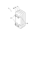
- the external device heat exchanger 3 includes a heat exchanger body 31, an electric heater 35, a heat insulating portion 36, a cooling liquid pipe 37, and a heat medium pipe 38.
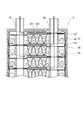
- FIG. 3 is a cross-sectional view showing a schematic configuration of the external equipment heat exchanger 3 included in the heat management system 1.
- the heat exchanger body 31 includes a heat dissipation unit 32 that dissipates heat from the external device cooling system 4 using the cooling liquid from the external device cooling system 4 as a medium.
- the heat exchanger body 31 is provided with a heat receiving portion 33 that receives the heat from the external device cooling system 4 radiated by the heat radiating portion 32 into the heat medium, and a heat storage provided between the heat radiating portion 32 and the heat receiving portion 33. And a section 34.
- the heat radiating section 32 is made of a material having a high thermal conductivity such as stainless steel (SUS316 or SUS304) or aluminum so that the heat from the external device cooling system 4 can be efficiently radiated by the cooling liquid from the external device cooling system 4. It is composed by.
- the heat radiating section 32 is provided with a flow path 321 for flowing the cooling liquid and then an appropriate method such as brazing so that the cooling liquid flowing from the cooling liquid pipe 37 can perform heat exchange without leaking. It is sealed by.
- the heat radiating section 32 is provided for one external device heat exchanger 3 in one set or in two or more sets.
- the heat receiving part 33 is made of, for example, stainless steel (SUS316 or SUS304) or aluminum similarly to the heat radiating part 32, so that the heat medium can efficiently receive the heat from the heat radiating part 32 transferred through the heat storage part 34. It is made of a material having high thermal conductivity such as.
- the heat receiving part 33 is provided with a flow path 331 for flowing the heat medium similarly to the heat radiating part 32 so that heat exchange can be performed without leaking the heat medium, and then an appropriate method such as brazing is used. It is sealed.
- the heat receiving unit 33 is provided with one set or two or more sets for one external device heat exchanger 3.
- the heat storage part 34 receives heat from the heat dissipation part 32 between the heat dissipation part 32 and the heat reception part 33, and the heat reception part 33 receives the heat, for example, the heat dissipation part 32 and the heat reception part. It is provided so as to fill the space between 33 and the heat storage material.
- the heat storage part 34 has a necessary contact area with the heat dissipation part 32 and the heat receiving part 33 so that heat can be efficiently transferred between the heat dissipation part 32 and the heat receiving part 33.
- a vanadium dioxide (VO 2 ) based heat storage material can be used for example.
- the heat storage section 34 may use a heat storage material other than the above-described vanadium dioxide-based heat storage material.
- the electric heater 35 is provided so as to cover the heat dissipation portion 32, the heat receiving portion 33, and the heat storage portion 34.
- the electric heater 35 heats the heat storage unit 34 by using the electric power supplied from the outside when the traveling battery is charged, for example. That is, the electric heater 35 functions as an electric heating unit.
- the heat storage unit 34 can store the heat heated by the electric heater 35.
- the electric heater 35 may cover at least the heat storage unit 34 so that the heat storage unit 34 can be heated.
- the heat insulating section 36 is provided between the electric heater 35 and the heat insulating section 36.
- the heat insulating portion 36 covers the heat exchanger body 31 and the electric heater 35 from the outside.
- the cooling liquid pipe 37 is a pipe line connected to the cooling liquid circuit CL in order to circulate the cooling liquid between the external device cooling system 4 and the flow passage 321 of the heat dissipation unit 32.
- the heat medium pipe 38 is used to circulate the heat medium between the components of the air conditioner in the heat management system 10 such as the external equipment heat exchanger 3 and the HVAC unit 60 and the flow path 331 of the heat receiving section 33. It is a conduit connected to the medium circuit HM.
- the compressor 5 is provided in the heat medium flow path of the heat management system 1 after the external device heat exchanger 3 and before the indoor heat exchanger 6.
- the compressor 5 uses electric power as a power source.
- the compressor 5 compresses the heat medium that has passed through the external device heat exchanger 3.
- the indoor heat exchanger 6 is provided in the heat medium flow path of the heat management system 1 after the compressor 5 and before the expansion valve TV in the flow of the heat medium circuit HM.
- the indoor heat exchanger 6 specifically faces the room that is the target of heat management of the heat management system 1, and functions as a condenser that radiates the heat held by the heat medium to the air in the room.
- the expansion valve TV is provided in the heat medium circuit HM14 connecting between the indoor heat exchanger 6 and the outdoor heat exchanger 2.
- the expansion valve TV decompresses and expands the heat medium that has passed through the indoor heat exchanger 6 to a state where it is easy to evaporate, and secures an optimum flow rate inside the evaporator.
- the outdoor heat exchanger 2 raises the temperature of the heat medium to be passed by the liquid heat medium removing heat from the outdoor air.
- the heat medium that has passed through the outdoor heat exchanger 2 changes from liquid to gas.
- the external device heat exchanger 3 receives the exhaust heat from the external device 40 via the cooling liquid of the external device cooling system 4.
- the external device heat exchanger 3 causes the heat medium to receive the exhaust heat from the external device 40 to further raise the temperature of the heat medium. Further, in the external device heat exchanger 3, the heat from the cooling liquid is held in the heat storage unit 34 provided between the heat radiating unit 32 and the heat receiving unit 33, and then transferred to the heat medium. That is, the external device heat exchanger 3 stores the heat generated by the external device 40 and exchanges heat with the heat medium.
- the compressor 5 compresses the heat medium whose temperature has risen by the outdoor heat exchanger 2 and the external equipment heat exchanger 3 to further raise the temperature of the heat medium.
- the indoor heat exchanger 6 condenses the heat medium whose temperature has been raised by the compressor 5, radiates the heat held by the heat medium to the indoor air, and raises the temperature of the indoor air.
- the heat medium that radiates heat is liquefied and expanded by the expansion valve TV to enter the outdoor heat exchanger 2.
- the thermal management system 1 repeats this cycle with the above steps as one cycle.
- the heat management system 1 configured as described above receives heat from the cooling liquid of the external equipment cooling system 4 by providing the external equipment heat exchanger 3 between the compressor 5 and the indoor heat exchanger 6. You can According to the heat management system 10 configured as described above, the flow rate of the heat medium as gas is increased by warming the heat medium flowing to the compressor 5 at low temperature. Then, according to the heat management system 1 configured as described above, it is possible to receive heat from the external device 40 and raise the temperature of the heat medium. Therefore, according to the heat management system 1, even when the temperature of the heat medium cannot be raised by the outdoor heat exchanger 2 such that the outside air temperature is ⁇ 10 ° C. or less, the heat pump consumes less energy to warm the air. The method can be used to raise the temperature in the passenger compartment.
- the heat storage part 34 is provided between the heat dissipation part 32 and the heat receiving part 33, heat generated by the external device 40 via the heat dissipation part 32. Can be used for raising the temperature of the heat medium by receiving heat and holding it for a predetermined time. Therefore, according to the heat management system 1, the heat storage unit 34 holds the heat generated from the external device 40 such as the traveling motor, the inverter, or the traveling battery while the electric vehicle is traveling, and the heat medium rises at the time of starting. Used for warmth. According to the heat management system 1, since the heat storage unit 34 includes the external device cooling system 4, it is possible to accelerate the temperature rise of the heat medium immediately after the start.
- the heat management system 1 includes the external equipment heat exchanger 3 that operates as described above, the work load of the compressor 5 used for raising the temperature of the heat medium is higher than that of a general heat pump type air conditioner. Can be reduced. Therefore, according to the heat management system 1, it is possible to suppress the energy consumption amount used for heat management.
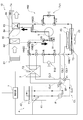
- FIG. 4 is a functional block diagram showing a schematic configuration of the thermal management system 10 according to the second embodiment of the present invention.
- the thermal management system 10 describes a more specific configuration of the thermal management system according to the present invention.
- the heat management system 10 is, like the heat management system 1 described above, a heat pump type air conditioner that uses air heat outside the room as a heat source.
- the heat management system 10 is different from the above-described heat management system 1 in that it has a function of not only heating but also cooling, and raises or lowers the temperature of the vehicle interior to adjust it to a desired temperature.
- the description of the same configuration as the thermal management system 1 described above will be omitted.
- the heat management system 10 has an outdoor heat exchanger 2, an external equipment heat exchanger 3, an external equipment cooling system 4, a compressor 5, and an HVAC (Heating) as its main components. , Ventilation, and Air Conditioning) unit 60 and a control unit 7.
- the configuration of the heat management system 10 will be described separately for a cooling liquid circuit that circulates a cooling liquid for heat exchange and a heat medium circuit that circulates a heat medium for heat exchange. Then, in the present embodiment, the operation of the thermal management system 10 at the time of exchanging heat between the cooling liquid and the heat medium will be described.
- External heat exchanger 3 and external equipment cooling system 4 are connected to the coolant circuit.
- the external device cooling system 4 connected to the cooling liquid circuit CL is, as described above, an external device such as a running motor 41 of the electric vehicle, an inverter 42 for controlling the motor 41, or a running battery (not shown).
- the external device cooling system 4 includes a cooling heat exchanger 43 that radiates a cooling liquid such as LLC (Long Life Coolant) of an external device such as the motor 41.
- the external device cooling system 4 includes cooling passages CL1, CL2, CL5, and CL6 that form a cooling liquid circuit CL that can circulate a cooling liquid between the external device and the cooling heat exchanger 43, and the cooling heat exchange.
- a pump P provided in the flow path CL5 for sending the cooling liquid from the container 43 to the external device.
- a four-way valve V1 for controlling the flow path and flow rate of the cooling liquid flowing into the external device, the external device heat exchanger 3, and the cooling heat exchanger 43 is provided. Further, between the flow path CL2, the flow path CL4, and the flow path CL6 of the external device cooling system 4, the flow path of the cooling liquid flowing out from the external device, the external device heat exchanger 3, and the cooling heat exchanger 43. And a four-way valve V2 for controlling the flow rate.
- a bypass passage BP which is a passage connecting the four-way valve V1 and the four-way valve V2, is provided between the four-way valve V1 and the four-way valve V2.
- the cooling liquid flow path CL in the external device cooling system 4 is provided with the four-way valve V1, the four-way valve V2, and the bypass path BP to form a path through which the cooling liquid circulates between the external devices such as the motor 41 and the inverter 42. can do.
- the outdoor heat exchanger 2, the compressor 5, the HVAC unit 60, and the external device heat exchanger 3 are connected to the heat medium circuit HM.
- the heat medium circuit HM is composed of the flow paths HM22 to HM25.
- the outdoor heat exchanger 2 performs heat exchange between the heat medium and the outdoor air as described above.
- the outdoor heat exchanger 2 functions as a condenser that radiates heat from the heat medium to the outdoor air, and an evaporator that absorbs heat from the outdoor air to the heat medium.
- a fan 23 that blows air to the outdoor heat exchanger 2 and the cooling heat exchanger 43 of the external device cooling system 4 is provided outside the outdoor heat exchanger 2.
- the compressor 5 also compresses the heat medium whose temperature has been raised by the outdoor heat exchanger 2 and the external equipment heat exchanger 3 to further raise the temperature of the heat medium.
- a gas-liquid separator 51 may be provided at the front stage of the compressor 5. The gas-liquid separator 51 is provided to prevent the liquid refrigerant that has not been evaporated by the evaporator 62 from being compressed (liquid compressed) by the compressor 5. The gas-liquid separator 51 separates the refrigerant flowing from the evaporator 62 into gas and liquid and sends only the gaseous refrigerant to the compressor 5.
- the HVAC unit 60 includes a blower 61, an evaporator 62, a condenser 63, an air passage adjusting unit 64, a housing 65, and a duct 66.
- the blower 61 blows air toward the evaporator 62 and the condenser 63 inside the housing 65.
- the evaporator 62 is connected to the outdoor heat exchanger 2 via the flow path HM22 and is connected to the compressor 5 via the flow path HM23.
- the flow path HM22 between the evaporator 62 and the external device heat exchanger 3 is provided with a three-way valve V7 that controls the flow rate of the heat medium to the evaporator 62.
- a three-way valve V8 that controls the flow rate of the heat medium to the evaporator 62 is provided in the flow path HM23 between the evaporator 62 and the compressor 5.
- the condenser 63 is connected to the compressor 5 via a flow passage HM24 and is connected to the outdoor heat exchanger 2 via a flow passage HM25.
- the air passage adjusting unit 64 adjusts the amount of wind passing through the condenser 63.
- the housing 65 houses the components of the HVAC unit 60.
- the duct 66 separates the wind that has passed through the condenser 63 and the wind that does not pass through the condenser 63 and sends the wind into the vehicle interior.
- an expansion valve TV1 for heating which bypasses the heat medium circuit HM and is similar to the above-described expansion valve, is provided.
- the expansion valve TV1 is provided with three-way valves V9 and V10 that adjust the flow rate of the heat medium to the expansion valve TV1.
- an expansion valve TV2 for cooling is provided between the outdoor heat exchanger 2 and the three-way valve V4 of the external device heat exchanger 3 so as to bypass the heat medium circuit HM.
- the expansion valve TV2 is provided with three-way valves V5 and V6 that adjust the flow rate of the heat medium of the expansion valve TV2.
- the external device heat exchanger 3 receives the heat generated by the external device cooling system 4 via the cooling liquid and exchanges heat with the heat medium.
- the flow path CL4 is connected to the four-way valve V2 between the flow paths CL2 and CL6 of the external device cooling system 4.
- the flow path CL3 is connected to the four-way valve V1 between the flow paths CL1 and CL5 of the external device cooling system 4. ing.
- the external device heat exchanger 3 can take in the cooling liquid from the cooling liquid circuit CL.
- the external device heat exchanger 3 is a three-way valve provided in the heat medium circuit HM from the outdoor heat exchanger 2 toward the HVAC unit 60 in order to receive the heat received from the external device cooling system 4 in the heat medium. It is connected to V3 and V4. By being connected to the three-way valves V3 and V4, the external device heat exchanger 3 can take in the heat medium of the heat medium circuit HM.
- the external device heat exchanger 3 includes a heat radiating portion 32 for flowing a cooling liquid, a heat receiving portion 33 for flowing a heat medium, and a heat storage portion 34 provided between the heat radiating portion 32 and the heat receiving portion 33. 31, an electric heater 35, and a heat insulating portion 36.
- the heat storage unit 34 stores the heat from the heat radiation unit 32 and causes the heat receiving unit 33 to receive the heat.
- the control unit 7 includes a thermometer T1 for measuring the cooling liquid temperature of the motor 41, a thermometer T2 for measuring the temperature of the heat storage unit 34 of the external device heat exchanger 3, and a cooling liquid temperature of the outdoor heat exchanger 2.
- a thermometer T3 for measuring and a thermometer T4 for measuring the temperature inside the compartment of the electric vehicle are connected.
- the control unit 7 measures the measured temperatures of the thermometers T1 to T4, the temperature of the cooling liquid of the motor 41, the temperature of the heat storage unit 34 of the external device heat exchanger 3, the temperature of the cooling liquid of the outdoor heat exchanger 2, and the temperature inside the vehicle.
- the operation of the thermal management system 1 is controlled by comparing each threshold value (set temperature).
- control unit 7 controls the measured temperatures of the thermometers T1 to T3, the motor 41, the external device heat exchanger 3, the outdoor heat exchanger 2, the respective coolant temperatures, and the threshold values (settings) of the vehicle interior temperature. Temperature) and four-way valves V1, V2, and three-way valves including four-way valve V1 and four-way valve V2 for the coolant of external equipment heat exchanger 3 and three-way valve V3 and three-way valve V4 for the heat medium. Opening / closing control of V3 to V10 is performed. The opening / closing control of the four-way valves V1 and V2 and the three-way valves V3 to V10 in the thermal management system 1 will be described later.
- control unit 7 controls the power-on and power-off during charging, which will be described later, for the heat storage unit 34 included in the external device heat exchanger 3.
- the control unit 7 may perform various controls related to the thermal management system 10, such as operation control of the HVAC unit 60 and operation control of the compressor 5.
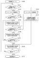
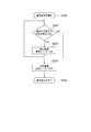
- FIG. 5 is a flowchart showing the operation of the thermal management system according to the second embodiment.
- the operation of the control unit 7 when the thermal management system 10 is operating will be described with reference to FIGS. 4 and 5.
- the heat management system 10 starts air conditioning operation when the electric vehicle equipped with this system is powered on, or when the system is powered on (S100).
- the control unit 7 compares the measured temperature of the thermometer T4 in the vehicle compartment with the set temperature in the vehicle compartment to determine whether the measured temperature of the thermometer T4 is lower than the set temperature (S101).
- the control unit 7 executes the heat pump type heating operation by the heat management system 10 (S102).
- the set temperature that is used for the determination in S101 and that is compared with the actually measured temperature of the thermometer T4 is the air temperature (for example, 20 ° C.) that serves as a reference for determining whether or not the heating operation is necessary.
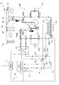
- FIG. 6 is a functional block diagram showing the operation immediately after the start of heating operation in the heat management system 10 according to the second embodiment.
- the control unit 7 controls the four-way valves V1 and V2 and the three-way valves V3 to V10 so that the heat of the cooling liquid circuit CL circulates in the heat medium circuit HM.
- the control unit 7 controls the open / closed states of the three-way valves V3 to V10 such that the heat medium flowing out from the outdoor heat exchanger 2 passes through the gas-liquid separator 51, the compressor 5, the condenser 63, and the heating expansion valve TV1.
- the cooling expansion valve TV2, the external device heat exchanger 3, and the evaporator 62 are controlled so as not to pass through.
- the heat medium circuit HM includes the flow passage HM21, the flow passage HM22, the flow passage HM23, the gas-liquid separator from the outdoor heat exchanger 2 as indicated by the thick solid line and the arrow. 51, the compressor 5, the flow path HM24, the condenser 63, the flow path HM25, and the heating expansion valve TV1 in this order are circulation paths.
- the cooling liquid circuit CL becomes a path that circulates in the order of the flow path CL5, the pump P, the motor 41, the inverter 42, and the flow path CL6, as indicated by the broken line and the arrow in FIG.
- the control unit 7 compares the measured temperature of the cooling liquid thermometer T1 of the motor 41 with the set temperature of the cooling liquid of the motor 41, and the measured temperature of the thermometer T1 is lower than the first set temperature (set temperature 1). It is determined whether it is high (S103).
- the first set temperature of the cooling liquid is a temperature of the cooling liquid that becomes a threshold value of whether or not the cooling liquid of the external device cooling system 4 is allowed to flow into the external device heat exchanger 3.
- the control unit 7 operates the four-way valve V1 and the four-way valve V2 of the heat management system 10 to cool the external device heat exchanger 3.
- the liquid is caused to flow in and out (S104).
- the control unit 7 measures the temperature of the heat storage unit 34 of the external device heat exchanger 3 and the measured temperature and the heat storage unit of the thermometer T2. It is determined whether or not the actually measured temperature of the thermometer T2 is higher than the set temperature by comparing it with the set temperature of 34 (S105).
- the set temperature of the heat storage unit 34 is a temperature serving as a threshold value for determining whether or not to allow the heat medium to flow into the external device heat exchanger 3.
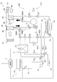
- FIG. 7 is a functional block diagram showing the operation of heat exchange by the external device heat exchanger 3 in the heat management system 10 according to the second embodiment. That is, in the heat management system 10, when the process of S106 is performed, the heat exchange between the cooling liquid and the heat medium can be performed by the external device heat exchanger 3.
- the heat medium circuit HM includes the flow path HM21, the external device heat exchanger 3, the flow path HM22, the flow path HM23, the gas-liquid as shown by the thick solid line and the arrow in FIG.
- the separator 51, the compressor 5, the flow path HM24, the condenser 63, the flow path HM25, and the heating expansion valve TV1 circulate in this order.
- the cooling liquid circuit CL is, as shown by a broken line and an arrow in FIG. 7, from the external device heat exchanger 3, the flow passage CL3, the flow passage CL5, the pump P, the motor 41, the inverter 42, the flow passage CL6, and the flow passage. It becomes a route that circulates in the order of the route CL4.
- the control unit 7 returns to the determination process of S103.
- the control unit 7 compares the measured temperature of the cooling liquid thermometer T1 of the motor 41 with the set temperature of the cooling liquid of the motor 41, and the measured temperature of the thermometer T1 is lower than the second set temperature (set temperature 2). It is determined whether it is high (S107).
- the second set temperature of the cooling liquid is a temperature of the cooling liquid that becomes a threshold value of whether the cooling liquid of the external device cooling system 4 flows into the cooling heat exchanger 43 to radiate heat.
- the control unit 7 operates the four-way valve V1 and the four-way valve V2 of the heat management system 10 to add to the external device heat exchanger 3.
- FIG. 8 is a functional block diagram showing the operation of heat exchange by the external equipment heat exchanger 3 and the cooling heat exchanger 43 in the heat management system 10 according to the second embodiment.
- the cooling liquid circuit CL in the cooling liquid circuit CL, the flow passage CL5 for flowing the cooling liquid into the external device includes the flow passage CL3 from the external device heat exchanger 3 and the cooling heat exchanger 43.
- the cooling liquid flows in from the flow path CL1.
- the flow passage CL6 for flowing the cooling liquid from the external device is cooled to the flow passage CL4 to the external device heat exchanger 3 and the flow passage CL2 to the cooling heat exchanger 43. Liquid flows out.
- the heat medium circuit HM is similar to FIG. 7 in that from the outdoor heat exchanger 2, the flow path HM21, the external device heat exchanger 3, the flow path HM22, the flow path HM23, the gas-liquid separator 51, the compressor 5, The flow path HM24, the condenser 63, the flow path HM25, and the heating expansion valve TV1 circulate in this order.
- FIG. 9 is a functional block diagram showing an operation during a cooling operation in the heat management system according to the second embodiment.
- the controller 7 executes the heat pump type cooling operation by the heat management system 10 (S109).
- the control unit 7 controls the open / closed states of the three-way valves V3 to V10 provided in the heat medium circuit HM of the heat management system 10 so that the cooling liquid flowing out from the outdoor heat exchanger 2 is operated.
- the gas-liquid separator 51, the compressor 5, the evaporator 62, and the condenser 63 are controlled so as to pass through.
- the control unit 7 controls the open / closed states of the three-way valves V3 to V10 so as not to pass through the heating expansion valve TV1, the external device heat exchanger 3, and the evaporator 62. Yes (S110). That is, during the cooling operation, the heat medium circuit HM includes the flow path HM21, the cooling expansion valve TV2, the flow path HM22, the evaporator 62, the gas-liquid separator 51, the compressor 5, and the flow path from the outdoor heat exchanger 2.
- the HM 24, the condenser 63, and the flow path HM 25 serve as a circulation path in this order.
- the control unit 7 proceeds to the processing of S108, and causes the cooling liquid to flow into and out of the cooling heat exchanger 43. That is, during the cooling operation, the cooling liquid circuit CL serves as a path that circulates from the cooling heat exchanger 43 in the order of the flow path CL1, the flow path CL5, the pump P, the external device, the flow path CL6, and the flow path CL2.
- the cooling operation is performed in the heat management system 10
- the operation is performed in the cycle opposite to that of the heating operation described above. That is, in the cooling operation of the heat management system 10, the evaporator 62 receives the heat in the room, and the outdoor heat exchanger 2 functions as a condenser to radiate the heat in the room to the outside.
- the control unit 7 confirms whether or not the air conditioning operation has ended (S111).
- the control unit 7 repeats the above-described processing from S101 to S110 until the air conditioning operation ends (S111: NO).
- the control unit 7 ends the above processing.
- the heat management system 10 causes the evaporator 62 to cool the outside air to agglomerate and remove the water vapor contained in the outside air, and the steam-excluded air is warmed in the condenser 63 to enter the room. send.
- the control unit 7 of the heat management system 10 determines whether to heat the heat medium flowing through the heat medium circuit HM by the external device heat exchanger 3 according to the temperature in the room.
- the heat management system 10 includes the control unit 7 that controls the cooling liquid and the heat medium that flow in the external device heat exchanger 3. Therefore, the heat management system 10 according to the present embodiment suppresses energy consumption by appropriately controlling the operation of the external equipment heat exchanger 3 according to the temperatures of the room, the coolant, and the heat medium. The heating performance can be improved.
- FIG. 10 is a flow chart for showing the operation at the time of charging the storage battery in the thermal management system according to the second embodiment.
- the control unit 7 compares the measured temperature of the thermometer T2 that measures the temperature of the heat storage unit 34 with the set temperature of the heat storage unit 34. Then, it is determined whether the measured temperature of the thermometer T2 is higher than the set temperature (S201).
- the control unit 7 determines that the heat generated by the electric heater 35 can be stored in the heat storage unit 34, and switches the power supply of the electric heater 35. Is turned on (S202). After turning on the power source of the electric heater 35, the control unit 7 repeats the process of S201 and continues to determine whether or not heat can be stored in the heat storage unit 34.
- the control unit 7 determines that the heat generated by the electric heater 35 cannot be stored in the heat storage unit 34, and the power supply of the electric heater 35 is determined. The switch is turned off (S203). After turning off the power switch of the electric heater 35, the control unit 7 ends the process when the charging of the storage battery is completed (S204).
- the thermal management system 10 includes the electric heater 35 that can heat the heat storage section 34 of the external device cooling system 4. Therefore, according to the heat management system 10, it is possible to store thermal energy by receiving energy supplied from the outside, such as when charging a running battery in an electric vehicle. That is, according to the heat management system 10, heating performance can be improved by quickly obtaining heat energy immediately after the system is started.
- FIG. 11 is a functional block diagram showing a schematic configuration of the thermal management system according to the third embodiment of the present invention.
- a thermal management system 100 describes the configuration of another exemplary thermal management system according to the present invention.
- the thermal management system 100 is different from the thermal management system 10 described above in that the thermal management system 100 includes an injection circuit 70.
- the thermal management system 100 has the same configuration as the thermal management systems 1 and 10 described above, except for the configuration of the injection circuit 70 and its peripherals described above, and therefore description thereof will be omitted.
- the injection circuit 70 is provided between the inlet three-way valve V10 of the heating expansion valve TV1 and the inlet of the outdoor heat exchanger 2.
- the injection circuit 70 includes a gas-liquid separator 71 for cooling liquid.
- the gas-liquid separator 71 separates the heat medium that has flowed in from the condenser 63 via the heating expansion valve TV1 into gas and liquid.
- a gas component having a gas component is sent to the compressor 5.
- the gas component of the heat medium sent to the compressor 5 is compressed again and condensed in the condenser 63.
- the liquid component is sent to the outdoor heat exchanger 2.
- the liquid component of the heat medium sent to the outdoor heat exchanger 2 exchanges heat with the outdoor air.
- the heat management system 100 separates only the gas component from the heat medium of the gas-liquid mixture compressed by the compressor 5 by the injection circuit 70, and returns it to the compressor 5 again for compression. With this, in the heat management system 100, the flow rate of the heat medium is increased and the efficiency of heat exchange between the heat medium and air is improved. Further, in the heat management system 100, since only the liquid flows into the condenser 63 by the injection circuit 70, the heat exchange efficiency with the atmosphere can be improved. According to the heat management system 100, the efficiency is improved as compared with the heat management system 10 and the like, and the lower limit temperature that can secure the heating capacity can be expanded.
- the heat management system 100 like the heat management systems 1 and 10, has a difference between the outside air temperature and the temperature of the heat medium in an environment where the outside air temperature is lower than the minimum temperature of the heat medium, for example, in an extremely cold region. Even if it is small or there is no difference, the temperature in the room can be warmed up in a short time.
- the heat management system 100 by including the external device heat exchanger 3, it is possible to suppress energy consumption and improve heating performance.
- the present invention is not limited to the thermal management system according to the embodiment of the present invention, and includes all aspects included in the concept and claims of the present invention. Including. Further, the respective configurations may be appropriately and selectively combined so as to achieve at least a part of the above-mentioned problems and effects. For example, the shape, material, arrangement, size, etc. of each component in the above-described embodiment can be appropriately changed depending on the specific usage mode of the present invention.
- the present invention is not limited to, for example, an electric vehicle, but a vehicle such as a fuel cell vehicle that does not have an internal combustion engine that can be used as a heat source for heating, or an internal combustion engine such as a hybrid vehicle or a plug-in hybrid vehicle is not always operating. It is useful as an air conditioner used in a vehicle.
- the present invention can also be used as an air conditioner for a vehicle having an internal combustion engine.
- the present invention can also be used as an air conditioner for vehicles other than automobiles such as trains.
- the present invention is not limited to this.
- INDUSTRIAL APPLICABILITY The present invention can be used, for example, as a movement other than a vehicle such as a ship or as an air conditioning apparatus other than a moving body such as a building. In this case, the heating of the heat storage section 34 by the electric heater 35 can be always performed as long as the heat management system is powered.
- the present invention is not limited to this.
- the present invention can also be used as a heating device for various facilities.
Landscapes
- Engineering & Computer Science (AREA)
- Physics & Mathematics (AREA)
- Thermal Sciences (AREA)
- Mechanical Engineering (AREA)
- General Engineering & Computer Science (AREA)
- Life Sciences & Earth Sciences (AREA)
- Sustainable Development (AREA)
- Sustainable Energy (AREA)
- Chemical & Material Sciences (AREA)
- Combustion & Propulsion (AREA)
- Air-Conditioning For Vehicles (AREA)
Abstract
エネルギー消費を抑制して暖房性能を向上する。 熱管理システム(1)は、熱媒体と室外の空気との間で熱交換を行う室外熱交換器(2)と、室外熱交換器(2)により熱交換が行われた熱媒体を圧縮する圧縮機(5)と、圧縮機(5)で圧縮された熱媒体と室内の空気との間で熱交換を行う室内熱交換器(6)と、室外熱交換器(2)と圧縮機(5)との間に設けられ外部機器(40)が発生した熱と熱媒体との間で熱交換を行う外部機器熱交換器(3)と、を備える。
Description
本発明は、熱管理システムに関する。
近年、例えば車両用などの空気調和装置として、ヒートポンプ方式の冷凍回路を備える空気調和装置(以下「ヒートポンプ方式の空気調和装置」ともいう。)が用いられている。ヒートポンプ方式の空気調和装置は、空気調和の対象である室内の外部の空気と熱媒体(冷媒)との間で熱交換を行うことにより、空気調和に必要な熱を上記外部の空気から得ている。このため、ヒートポンプ方式の空気調和装置は、電力を用いて空気を加熱している電気式ヒータ、例えばPTC(Positive Temperature Coefficient)ヒータを用いる場合と比較して、空気調和、特に暖房時に用いるエネルギーを抑えられる(例えば、特許文献1乃至3参照)。
上述のようなヒートポンプ方式の空気調和装置は、空気を加熱するために熱源を必要としない。このため、ヒートポンプ方式の空気調和装置は、電気自動車や燃料電池自動車といった暖房時の熱源として利用可能な内燃機関を有しない車両、あるいはハイブリッド自動車やプラグインハイブリッド自動車といった内燃機関が常時稼働していない車両に用いられる空気調和装置として有用である。
しかしながら、ヒートポンプ方式の空気調和装置は、その原理として空気からの熱を暖房時の熱源として用いる。このため、従来のヒートポンプ方式の空気調和装置は、寒冷時のように、熱媒体の温度と外気温度との温度差が小さいまたは生じない場合には、十分に室内の温度が暖めにくいという課題が生じていた。
このようなヒートポンプ方式の空気調和装置における寒冷時の昇温の課題について、例えばヒートポンプに上述のPTCヒータのような電気式ヒータを組み合わせる、あるいはガスインジェクション式ヒートポンプを用いるといった対策が知られている。
しかし、電気式ヒータとヒートポンプ方式の空気調和装置とを組み合わせた場合には、電気式ヒータが電力を消費してしまうため、暖房時のエネルギー消費量が増加していた。特に、電気式ヒータとヒートポンプとを組み合わせて電気自動車の空気調和装置として用いた場合には、電気式ヒータが車両に搭載している走行用バッテリを消費してしまうため、航続距離が減少してしまうという課題が生じていた。また、ガスインジェクション式ヒートポンプを用いる空気調和装置であっても、例えば極寒地のように、外気温度が熱媒体の最低温度を下回る環境においては、十分に室内の温度が暖めにくいという課題が生じていた。
本発明は、上述の課題に鑑みてなされたものであり、その目的は、エネルギー消費を抑制して暖房性能を向上することができる熱管理システムを提供することにある。
上記目的を達成するために、本発明に係る熱管理システムは、室内の熱管理を行う熱管理システムであって、熱媒体と室外の空気との間で熱交換を行う室外熱交換器と、前記室外熱交換器により熱交換が行われた前記熱媒体を圧縮する圧縮機と、前記圧縮機で圧縮された前記熱媒体と前記室内の空気との間で熱交換を行う室内熱交換器と、前記室外熱交換器と前記圧縮機との間に設けられ外部機器が発生した熱と前記熱媒体との間で熱交換を行う外部機器熱交換器と、を備える。
本発明の一態様に係る熱管理システムにおいて、前記室外熱交換器は、前記室外の空気から受熱して前記熱媒体に放熱し、前記外部機器熱交換器は、前記外部機器から受熱して前記熱媒体に放熱し、前記圧縮機は、前記室外熱交換器及び前記外部機器熱交換器から受熱した前記熱媒体を圧縮して昇温し、前記室内熱交換器は、前記圧縮機により昇温された前記熱媒体により前記室内の空気を昇温する。
本発明の一態様に係る熱管理システムにおいて、前記外部機器熱交換器は、前記外部機器が発生した熱を蓄熱し、前記熱媒体との間で熱交換を行う。
本発明の一態様に係る熱管理システムにおいて、前記外部機器熱交換器は、前記外部機器が発生した熱を放熱する放熱部と、前記放熱部が放熱した熱を蓄熱する蓄熱部と、前記蓄熱部が蓄熱した熱を前記熱媒体に受熱させる受熱部と、を備える。
本発明の一態様に係る熱管理システムにおいて、前記外部機器熱交換器は、前記蓄熱部を加熱する電熱部を備える。
本発明によれば、エネルギー消費を抑制して暖房性能を向上することができる。
以下、本発明の実施の形態に係る熱管理システムについて図面を参照しながら説明する。熱管理システムは、例えば車両や建築物などの室内の熱管理を行う。以下の記載において、熱管理システムは、熱管理を行う対象である所定の空間として、電気自動車の車室内の空気調和を行うために電気自動車に搭載される、空気調和装置としての例について説明する。
[第1の実施の形態]
まず、本発明の第1の実施の形態に係る熱管理システムについて説明する。
まず、本発明の第1の実施の形態に係る熱管理システムについて説明する。
図1は、本発明の第1の実施の形態に係る熱管理システム1の概略構成を示すための、機能ブロック図である。第1の実施の形態において、熱管理システム1は、本発明に係る熱管理システムの基本的な構成を説明するものである。本実施の形態において、熱管理システム1は、車室内の温度を上昇させるために、その室内の外部にある空気熱を熱源として利用するヒートポンプ方式の暖房システムの一例である。
図1に示すように、本実施の形態に係る熱管理システム1は、熱媒体と室外の空気との間で熱交換を行う室外熱交換器2と、室外熱交換器2により熱交換が行われた熱媒体を圧縮する圧縮機5と、圧縮機5で圧縮された熱媒体と室内の空気との間で熱交換を行う室内熱交換器6と、室外熱交換器2と圧縮機5との間に設けられ外部機器40が発生した熱と熱媒体との間で熱交換を行う外部機器熱交換器3と、を備える。以下、熱管理システム1の構造及び動作を具体的に説明する。
熱管理システム1において、室外熱交換器2、外部機器熱交換器3、圧縮機5、及び室内熱交換器6の間には、熱媒体を循環可能な熱媒体回路HMが形成されている。熱媒体は、通常の空気調和装置において、一般に冷媒と称されるものと同様のものを用いることができる。熱媒体回路HMは、流路HM11~HM14により構成されている。流路HM11は、室外熱交換器2と外部機器熱交換器3との間を接続している。流路HM12は、外部機器熱交換器3と圧縮機5との間を接続している。流路HM13は、圧縮機5と室内熱交換器6との間を接続している。流路HM14は、室内熱交換器6と室外熱交換器2との間を接続している。熱管理システム1は、熱媒体回路HMにより、室外熱交換器2、外部機器熱交換器3、圧縮機5、及び室内熱交換器6が順に接続されることで、ヒートポンプ方式の冷凍回路を構成している。
外部機器40は、電気自動車の動力用モータ、あるいはモータの制御に用いられるインバータなど、熱管理システム1の外部に設けられている各種熱源である。一般に、電気自動車のモータやインバータの冷却には、外部機器熱交換器3と外部機器40との間に設けられているモータ、インバータ、あるいは走行用バッテリなどの外部機器40を冷却するためのLLC(Long Life Coolant)などの冷却液が用いられている。このため、外部機器40は、外部機器冷却システム4に組み込まれている。外部機器冷却システム4は、冷却液を循環可能な冷却液回路CLと、外部機器40と外部機器熱交換器3との間で冷却液を循環させるためのポンプPと、外部機器40と外部機器熱交換器3との間の冷却液の流量を制御するためのバルブVとを備える。
室外熱交換器2は、膨張弁TVにより膨張された熱媒体が流れ込み、熱媒体と室外の空気との間で熱交換を行う。熱管理システム1において、室外熱交換器2は、具体的には室外の空気から熱媒体に対して吸熱する蒸発器として機能する。
図1に示すように、外部機器熱交換器3は、熱媒体回路HMにおいて、室外熱交換器2と室内熱交換器6との間の流路HM12に設けられている。
図2は、熱管理システム1が備える外部機器熱交換器3の概略構成を示すための、模式図である。図2に示すように、外部機器熱交換器3は、熱交換器本体31と、電熱ヒータ35と、断熱部36と、冷却液配管37と、熱媒体配管38とを備える。
図3は、熱管理システム1が備える外部機器熱交換器3の概略構成を示すための、断面図である。図3に示すように、熱交換器本体31は、外部機器冷却システム4からの冷却液を媒体として外部機器冷却システム4からの熱を放熱する放熱部32と、を備える。また、熱交換器本体31は、放熱部32が放熱した外部機器冷却システム4からの熱を熱媒体に受熱させる受熱部33と、放熱部32と受熱部33との間に設けられている蓄熱部34とを備える。
放熱部32は、外部機器冷却システム4からの冷却液により外部機器冷却システム4からの熱を効率よく放熱できるように、例えばステンレススチール(SUS316あるいはSUS304)やアルミニウムなどの高い熱伝導率を有する素材により構成されている。放熱部32は、冷却液配管37から流れ込む冷却液を漏出することなく熱交換を行うことができるように、冷却液を流すための流路321が設けられた上でロウ付けなどの適宜な手法により密封されている。放熱部32は、1つの外部機器熱交換器3に対して、1組又は2以上の複数組が備えられている。
受熱部33は、蓄熱部34を介して伝熱された放熱部32からの熱を効率よく熱媒体に受熱させることができるように、放熱部32と同じく例えばステンレススチール(SUS316あるいはSUS304)やアルミニウムなどの高い熱伝導率を有する素材により構成されている。受熱部33は、熱媒体を漏出することなく熱交換を行うことができるように、放熱部32と同じく熱媒体を流すための流路331が設けられた上でロウ付けなどの適宜な手法により密封されている。受熱部33は、1つの外部機器熱交換器3に対して、1組又は2以上の複数組が備えられている。
蓄熱部34は、1組の放熱部32と受熱部33との間において、放熱部32から受熱して、その熱を受熱部33に受熱させることができるように、例えば放熱部32と受熱部33との間を蓄熱材料により充填するようにして設けられている。蓄熱部34は、放熱部32及び受熱部33との間において効率よく伝熱することができるように、放熱部32及び受熱部33との必要な接触面積が確保されている。蓄熱部34は、例えば二酸化バナジウム(VO2)系の蓄熱材料を用いることができる。なお、蓄熱部34は、上述の二酸化バナジウム系の蓄熱材料以外の蓄熱材料を用いてもよい。
電熱ヒータ35は、放熱部32、受熱部33、及び蓄熱部34を覆うように設けられている。電熱ヒータ35は、例えば走行用バッテリの充電時に外部から供給される電力を利用して蓄熱部34を加熱する。つまり、電熱ヒータ35は、電熱部として機能する。蓄熱部34は、電熱ヒータ35により加熱された熱を蓄熱することができる。電熱ヒータ35は、蓄熱部34を加熱することができるように、少なくとも蓄熱部34を覆っていればよい。断熱部36は、電熱ヒータ35と断熱部36との間に設けられている。断熱部36は、熱交換器本体31と電熱ヒータ35とを外側から覆っている。冷却液配管37は、外部機器冷却システム4と放熱部32の流路321との間で冷却液を循環させるために、冷却液回路CLに接続されている管路である。熱媒体配管38は、外部機器熱交換器3及びHVACユニット60などの熱管理システム10における空気調和装置の構成要素と受熱部33の流路331との間で熱媒体を循環させるために、熱媒体回路HMに接続されている管路である。
図4に示すように、圧縮機5は、熱管理システム1の熱媒体の流路において、外部機器熱交換器3の後段であり室内熱交換器6の前段に設けられている。圧縮機5は、動力源として電力を用いる。圧縮機5は、外部機器熱交換器3を経由した熱媒体を圧縮する。
室内熱交換器6は、熱管理システム1の熱媒体の流路において、熱媒体回路HMの流れにおいて圧縮機5の後段であり膨張弁TVの前段に設けられている。室内熱交換器6は、具体的には熱管理システム1の熱管理の対象である室内に面していて、熱媒体が保持している熱を室内の空気に放熱する凝縮器として機能する。
膨張弁TVは、室内熱交換器6と室外熱交換器2との間を接続している熱媒体回路HM14に設けられている。膨張弁TVは、室内熱交換器6を通過した熱媒体を蒸発しやすい状態に減圧膨張し、蒸発器内部の最適流量を確保する。
次いで、以上構造を説明した熱管理システム1の動作について説明する。
室外熱交換器2は、液体の熱媒体が室外の空気から熱を奪うことにより、通過させる熱媒体の温度を上昇させる。室外熱交換器2を通過した熱媒体は、液体から気体に変化する。
室外熱交換器2は、液体の熱媒体が室外の空気から熱を奪うことにより、通過させる熱媒体の温度を上昇させる。室外熱交換器2を通過した熱媒体は、液体から気体に変化する。
外部機器熱交換器3は、外部機器冷却システム4の冷却液を介して外部機器40からの排熱を受熱する。外部機器熱交換器3は、この外部機器40からの排熱を熱媒体に受熱させることにより、熱媒体の温度をさらに上昇させる。また、外部機器熱交換器3は、放熱部32と受熱部33との間に設けられている蓄熱部34に冷却液からの熱を保持させた後、熱媒体に渡している。つまり、外部機器熱交換器3は、外部機器40が発生した熱を蓄熱して熱媒体との間で熱交換を行う。
圧縮機5は、室外熱交換器2及び外部機器熱交換器3により温度が上昇した熱媒体を圧縮して、さらに熱媒体を昇温させる。
室内熱交換器6は、圧縮機5により温度が上昇した熱媒体を凝縮させて、熱媒体が保持している熱を室内の空気に放熱して、室内の空気を昇温する。熱管理システム10において、放熱した熱媒体は、液化して膨張弁TVにより膨張されて室外熱交換器2に入る。熱管理システム1は、以上のステップを1サイクルとして、このサイクルを繰り返す。
以上のように構成された熱管理システム1は、圧縮機5と室内熱交換器6との間に外部機器熱交換器3を設けることにより、外部機器冷却システム4の冷却液から熱を受け取ることができる。以上のように構成された熱管理システム10によれば、低温時に圧縮機5に流れる熱媒体を温めることにより、ガスとしての熱媒体の流量を増やしている。そして、以上のように構成された熱管理システム1によれば、外部機器40からの熱を受熱して熱媒体を昇温させることができる。従って、熱管理システム1によれば、例えば外気温度が-10℃以下といった室外熱交換器2によっては熱媒体の昇温ができない場合であっても、空気を暖めるためのエネルギー消費量が少ないヒートポンプ方式を用いて車室内の温度を上昇させることができる。
熱管理システム1によれば、外部機器熱交換器3において、放熱部32と受熱部33との間に蓄熱部34が設けられているため、放熱部32を介して外部機器40が発した熱を受熱し所定時間保持して熱媒体の昇温に利用することができる。従って、熱管理システム1によれば、例えば電気自動車の走行中に走行用モータ、インバータ、あるいは走行用バッテリなどの外部機器40から発した熱を蓄熱部34が保持して始動時に熱媒体の昇温に用いる。熱管理システム1によれば、蓄熱部34が外部機器冷却システム4を備えることにより、始動直後の熱媒体の昇温を早めることができる。
熱管理システム1は、上述のように動作する外部機器熱交換器3を備えることにより、一般のヒートポンプ方式の空気調和装置と比較して熱媒体の昇温に用いられる圧縮機5の仕事量を削減することができる。従って、熱管理システム1によれば、熱管理に用いられるエネルギー消費量を抑制することができる。
[第2の実施の形態]
次いで、本発明の第2の実施の形態に係る熱管理システムについて説明する。
次いで、本発明の第2の実施の形態に係る熱管理システムについて説明する。
図4は、本発明の第2の実施の形態に係る熱管理システム10の概略構成を示すための、機能ブロック図である。第2の実施の形態において、熱管理システム10は、本発明に係る熱管理システムについて、より具体的な構成を説明するものである。本実施の形態において、熱管理システム10は、先に説明した熱管理システム1と同様に、その室内の外部にある空気熱を熱源として利用するヒートポンプ方式の空気調和装置である。熱管理システム10は、暖房のみならず冷房の機能も有し、車室内の温度を上昇または下降させて所望の温度に調整するものである点が上述の熱管理システム1と相違する。なお、本実施の形態において、先に説明した熱管理システム1と同様の構成については説明を省略する。
図4に示すように、熱管理システム10は、その主要な構成要素として、室外熱交換器2と、外部機器熱交換器3と、外部機器冷却システム4と、圧縮機5と、HVAC(Heating, Ventilation, and Air Conditioning)ユニット60と、制御部7とを備える。熱管理システム10の構成について、冷却液を循環させて熱交換を行う冷却液回路と、熱媒体を循環させて熱交換を行う熱媒体回路とに分けて説明する。その上で、本実施の形態では、冷却液と熱媒体との間で熱交換を行う際の熱管理システム10の動作について説明する。
冷却液回路には、外部機器熱交換器3、及び、外部機器冷却システム4が接続されている。
冷却液回路CLに接続されている外部機器冷却システム4は、先に説明した通り、電気自動車の走行用のモータ41、モータ41の制御用のインバータ42、あるいは不図示の走行用バッテリなどの外部機器を冷却するためのシステムである。外部機器冷却システム4は、モータ41などの外部機器のLLC(Long Life Coolant)などの冷却液を放熱する冷却用熱交換器43を備える。また、外部機器冷却システム4は、外部機器と冷却用熱交換器43との間で冷却液を循環可能な冷却液回路CLを構成する流路CL1,CL2,CL5,CL6と、冷却用熱交換器43から外部機器に冷却液を送るために流路CL5に設けられているポンプPとを備える。
外部機器冷却システム4の流路CL1、流路CL3、及び流路CL5の間には、モータ41やインバータ42などの外部機器、外部機器熱交換器3、及び冷却用熱交換器43との間において、外部機器、外部機器熱交換器3、及び冷却用熱交換器43に流入する冷却液の流路と流量とを制御する四方弁V1が設けられている。また、外部機器冷却システム4の流路CL2、流路CL4、及び流路CL6の間には、外部機器、外部機器熱交換器3、及び冷却用熱交換器43から流出する冷却液の流路と流量とを制御するために四方弁V2が設けられている。四方弁V1と四方弁V2との間には、四方弁V1と四方弁V2とを接続する流路であるバイパス路BPが設けられている。外部機器冷却システム4における冷却液流路CLは、四方弁V1、四方弁V2、及びバイパス路BPを備えることにより、冷却液がモータ41やインバータ42などの外部機器の間を循環する経路を形成することができる。
熱媒体回路HMには、室外熱交換器2と、圧縮機5と、HVACユニット60と、外部機器熱交換器3とが接続されている。熱媒体回路HMは、流路HM22~HM25により構成されている。
室外熱交換器2は、先に説明した通り、熱媒体と室外の空気との間で熱交換を行う。室外熱交換器2は、熱媒体から室外の空気に対して放熱する凝縮器、及び室外の空気から熱媒体に対して吸熱する蒸発器として機能する。室外熱交換器2の外側には、室外熱交換器2、及び外部機器冷却システム4の冷却用熱交換器43に対して送風するファン23が設けられている。
圧縮機5も、先に説明した通り、室外熱交換器2及び外部機器熱交換器3により温度が上昇した熱媒体を圧縮して、さらに熱媒体を昇温させる。圧縮機5の前段には、気液分離器51が設けられていてもよい。気液分離器51は、蒸発器62によって蒸発されなかった液体状の冷媒を圧縮機5によって圧縮(液圧縮)してしまうことを防ぐために設けられている。気液分離器51は、蒸発器62から流れ込む冷媒を気体と液体とに分離して圧縮機5に気体の冷媒のみを送る。
HVACユニット60は、ブロワ61と、蒸発器62と、凝縮器63と、風路調整部64と、筐体65と、ダクト66とを備える。
ブロワ61は、筐体65の内部において蒸発器62及び凝縮器63に向けて送風する。蒸発器62は、流路HM22により室外熱交換器2と接続し、流路HM23により圧縮機5と接続している。蒸発器62と外部機器熱交換器3との間の流路HM22には、蒸発器62への熱媒体の流量を制御する三方弁V7が設けられている。また、蒸発器62と圧縮機5との間の流路HM23には、蒸発器62への熱媒体の流量を制御する三方弁V8が設けられている。
凝縮器63は、流路HM24により圧縮機5と接続し、流路HM25により室外熱交換器2と接続している。風路調整部64は、凝縮器63を通過する風の量を調整する。筐体65はHVACユニット60の構成要素を収容する。ダクト66は、凝縮器63を通過した風と凝縮器63を通過しない風とを分離して車室内に風を送り出す。
熱媒体回路HMにおいて、HVACユニット60の凝縮器63と外部機器熱交換器3との間には、熱媒体回路HMをバイパスする、上述の膨張弁と同様の暖房用の膨張弁TV1が設けられている。膨張弁TV1には、膨張弁TV1への熱媒体の流量を調整する三方弁V9,V10が設けられている。また、熱媒体回路において、室外熱交換器2と外部機器熱交換器3の三方弁V4の間には、熱媒体回路HMをバイパスするように冷房用の膨張弁TV2が設けられている。膨張弁TV2には、膨張弁TV2の熱媒体の流量を調整する三方弁V5,V6が設けられている。
外部機器熱交換器3は、先に説明した通り、冷却液を介して外部機器冷却システム4が発生した熱を受熱し、熱媒体との間で熱交換を行う。外部機器熱交換器3は、外部機器冷却システム4の冷却液から受熱するために、流路CL4が外部機器冷却システム4の流路CL2と流路CL6との間の四方弁V2に接続されている。また、外部機器熱交換器3は、冷却液を外部機器冷却システム4に戻すために、流路CL3が外部機器冷却システム4の流路CL1と流路CL5との間の四方弁V1に接続されている。四方弁V1,V2に接続されていることにより、外部機器熱交換器3は、冷却液回路CLからの冷却液を取り入れることが可能である。また、外部機器熱交換器3は、外部機器冷却システム4から受熱した熱を熱媒体に受熱させるために、室外熱交換器2からHVACユニット60に向かう熱媒体回路HMに設けられている三方弁V3,V4に接続されている。三方弁V3,V4に接続されていることにより、外部機器熱交換器3は、熱媒体回路HMの熱媒体を取り入れることが可能である。外部機器熱交換器3は、冷却液を流す放熱部32と、熱媒体を流す受熱部33と放熱部32と受熱部33との間に設けられている蓄熱部34とを有する熱交換器本体31と、電熱ヒータ35と、断熱部36とを備える。熱管理システム1では、以上の構成により、放熱部32からの熱を蓄熱部34が蓄熱して受熱部33に受熱させる。
制御部7には、モータ41の冷却液温度を測定する温度計T1と、外部機器熱交換器3の蓄熱部34の温度を測定する温度計T2と、室外熱交換器2の冷却液温度を測定する温度計T3と、電気自動車の車室内の気温を測定する温度計T4とが接続されている。制御部7は、温度計T1~T4の実測温度と、モータ41の冷却液温度、外部機器熱交換器3の蓄熱部34の温度、室外熱交換器2の冷却液温度、及び車室内の気温それぞれの閾値(設定温度)とを比較して、熱管理システム1の動作を制御する。具体的には、制御部7は、温度計T1~T3の実測温度とモータ41、外部機器熱交換器3、室外熱交換器2、それぞれの冷却液温度、及び車室内の温度の閾値(設定温度)とを比較して、外部機器熱交換器3の冷却液の四方弁V1及び四方弁V2と、熱媒体の三方弁V3及び三方弁V4とを含む、四方弁V1,V2、及び三方弁V3~V10の開閉制御を行う。熱管理システム1における四方弁V1,V2、及び三方弁V3~V10の開閉制御については後述する。また、制御部7は、外部機器熱交換器3が備える蓄熱部34について、後述する充電時の電源オン及びオフの制御を行う。なお、制御部7は、HVACユニット60の動作制御、圧縮機5の動作制御など、熱管理システム10に関する各種制御を行ってもよい。
[熱管理システムの動作]
次いで、以上説明した熱管理システム10の動作について説明する。
次いで、以上説明した熱管理システム10の動作について説明する。
図5は、第2の実施の形態に係る熱管理システムの動作を示すための、フローチャートである。以下、図4及び図5を参照しつつ、熱管理システム10の運転時における制御部7の動作について説明する。
熱管理システム10は、このシステムが搭載されている電気自動車の電源が投入される、あるいはこのシステムの電源が投入されると、空調運転をスタートする(S100)。
制御部7は、車室内の温度計T4の実測温度と車室内の設定温度とを比較して、温度計T4の実測温度が設定温度より低いか否かを判断する(S101)。温度計T4の実測温度が設定温度より低い場合(S101:YES)、制御部7は、熱管理システム10によるヒートポンプ方式の暖房運転を実行する(S102)。ここで、S101の判断に用いられる、温度計T4の実測温度と比較する設定温度は、暖房運転が必要か否かの判断基準となる気温(例えば20℃)である。
図6は、第2の実施の形態に係る熱管理システム10における暖房運転開始直後の動作を示すための、機能ブロック図である。暖房運転の開始が判断されると、制御部7は、冷却液回路CLの熱が熱媒体回路HMを循環するように、四方弁V1,V2、及び三方弁V3~V10を制御する。制御部7は、三方弁V3~V10の開閉状態を、室外熱交換器2から流出した熱媒体が気液分離器51、圧縮機5、凝縮器63、及び暖房用膨張弁TV1を経由し、冷房用膨張弁TV2、外部機器熱交換器3、及び蒸発器62を経由しないように制御する。つまり、暖房運転開始直後において、熱媒体回路HMは、図6において太実線と矢印とで示すように、室外熱交換器2から、流路HM21、流路HM22、流路HM23、気液分離器51、圧縮機5、流路HM24、凝縮器63、流路HM25、暖房用膨張弁TV1の順に循環する経路となる。また、暖房運転開始直後において、冷却液回路CLは、図6において破線と矢印とで示すように、流路CL5、ポンプP、モータ41及びインバータ42、流路CL6の順に循環する経路となる。
制御部7は、モータ41の冷却液の温度計T1の実測温度とモータ41の冷却液の設定温度とを比較して、温度計T1の実測温度が第1の設定温度(設定温度1)より高いか否かを判断する(S103)。ここで、冷却液の第1の設定温度は、外部機器冷却システム4の冷却液を外部機器熱交換器3に流入させるか否かの閾値となる冷却液の温度である。温度計T1の実測温度が設定温度1より高い場合(S103:YES)、制御部7は、熱管理システム10の四方弁V1と四方弁V2とを操作して、外部機器熱交換器3に冷却液を流入及び流出させる(S104)。
一方、温度計T1の実測温度が設定温度1より低い場合(S103:NO)、制御部7は、外部機器熱交換器3の蓄熱部34の温度を測定する温度計T2の実測温度と蓄熱部34の設定温度とを比較して、温度計T2の実測温度が設定温度より高いか否かを判断する(S105)。ここで、蓄熱部34の設定温度は、熱媒体を外部機器熱交換器3に流入させるか否かの閾値となる温度である。温度計T2の実測温度が設定温度より高い場合(S105:YES)、制御部7は、熱管理システム10の三方弁V3と三方弁V4とを操作して、外部機器熱交換器3に対して熱媒体を流入及び流出させるようにする(S106)。図7は、第2の実施の形態に係る熱管理システム10において外部機器熱交換器3による熱交換の動作を示すための、機能ブロック図である。つまり、熱管理システム10において、S106の処理が行われるときは、外部機器熱交換器3により冷却液と熱媒体との間で熱交換が可能である。ここで、熱媒体回路HMは、図7において太実線と矢印とで示すように、室外熱交換器2から、流路HM21、外部機器熱交換器3、流路HM22、流路HM23、気液分離器51、圧縮機5、流路HM24、凝縮器63、流路HM25、暖房用膨張弁TV1の順に循環する経路となる。また、冷却液回路CLは、図7において破線と矢印とで示すように、外部機器熱交換器3から、流路CL3、流路CL5、ポンプP、モータ41及びインバータ42、流路CL6、流路CL4の順に循環する経路となる。一方、温度計T2の実測温度が設定温度より低い場合(S105:NO)、制御部7は、S103の判断処理に戻る。
制御部7は、モータ41の冷却液の温度計T1の実測温度とモータ41の冷却液の設定温度とを比較して、温度計T1の実測温度が第2の設定温度(設定温度2)より高いか否かを判断する(S107)。ここで、冷却液の第2の設定温度は、外部機器冷却システム4の冷却液を冷却用熱交換器43に流入させて放熱させるか否かの閾値となる冷却液の温度である。温度計T1の実測温度が設定温度2より高い場合(S107:YES)、制御部7は、熱管理システム10の四方弁V1と四方弁V2とを操作して、外部機器熱交換器3に加えて冷却用熱交換器43に対しても冷却液を流入及び流出させるようにする(S108)。図8は、第2の実施の形態に係る熱管理システム10において外部機器熱交換器3及び冷却用熱交換器43による熱交換の動作を示すための、機能ブロック図である。熱管理システム10において、S108の処理が行われるときは、外部機器熱交換器3により冷却液と熱媒体との間で熱交換を行うとともに、冷却用熱交換器43により冷却液と外部の空気との間で熱交換を行う。図8において破線と矢印とで示すように、冷却液回路CLにおいて、外部機器に冷却液を流入させる流路CL5には、外部機器熱交換器3からの流路CL3と冷却用熱交換器43からの流路CL1とからの冷却液が流入する。また、冷却液回路CLにおいて、外部機器からの冷却液を流出させる流路CL6には、外部機器熱交換器3への流路CL4と冷却用熱交換器43への流路CL2とに、冷却液が流出する。なお、熱媒体回路HMは、図7と同様に、室外熱交換器2から、流路HM21、外部機器熱交換器3、流路HM22、流路HM23、気液分離器51、圧縮機5、流路HM24、凝縮器63、流路HM25、暖房用膨張弁TV1の順に循環する経路となる。
図9は、第2の実施の形態に係る熱管理システムにおける冷房運転時の動作を示すための、機能ブロック図である。温度計T4の実測温度が設定温度より高い場合(S101:NO)、制御部7は、熱管理システム10によるヒートポンプ方式の冷房運転を実行する(S109)。冷房運転の開始が判断されると、制御部7は、熱管理システム10の熱媒体回路HMに設けられている三方弁V3~V10の開閉状態を、室外熱交換器2から流出した冷却液が気液分離器51、圧縮機5、蒸発器62、及び凝縮器63を経由するように制御する。また、冷房運転の開始が判断されると、制御部7は、三方弁V3~V10の開閉状態を、暖房用膨張弁TV1、外部機器熱交換器3、及び蒸発器62を経由しないように制御する(S110)。つまり、冷房運転時において、熱媒体回路HMは、室外熱交換器2から、流路HM21、冷房用膨張弁TV2、流路HM22、蒸発器62、気液分離器51、圧縮機5、流路HM24、凝縮器63、流路HM25の順に循環する経路となる。S110の処理後、制御部7は、S108の処理に進み、冷却用熱交換器43に対して冷却液を流入及び流出させるようにする。つまり、冷房運転時において、冷却液回路CLは、冷却用熱交換器43から、流路CL1、流路CL5、ポンプP、外部機器、流路CL6、流路CL2の順に循環する経路となる。熱管理システム10において、冷房運転を行うと、上述した暖房運転の場合とは逆のサイクルで運転する。すなわち、熱管理システム10の冷房運転は、蒸発器62が室内の熱を受熱し、室外熱交換器2が凝縮器として機能して室内の熱を室外に放熱する。
制御部7は、空調運転が終了したか否かを確認する(S111)。制御部7は、空調運転が終了するまでの間(S111:NO)は、上述のS101からS110までの処理を繰り返す。一方、空調運転が終了した場合には(S111:YES)、制御部7は、上述の処理を終了する。なお、除湿暖房運転時において、熱管理システム10は、蒸発器62で外気を冷却することにより外気に含まれる水蒸気を凝集して排除し、水蒸気を排除した空気を凝縮器63で温めて室内に送る。この場合において、熱管理システム10の制御部7は、室内の温度に応じて外部機器熱交換器3により熱媒体回路HMを流れる熱媒体の加温を行うか否かの判断を行う。
以上説明したように、本実施の形態に係る熱管理システム10によれば、外部機器熱交換器3に流れる冷却液及び熱媒体を制御する制御部7を備える。このため、本実施の形態に係る熱管理システム10によれば、室内、冷却液、及び熱媒体の温度に応じて適切に外部機器熱交換器3を動作制御することにより、エネルギー消費を抑制して暖房性能を向上することができる。
[充電時の動作]
次いで、以上説明した熱管理システム10が電気自動車に搭載されている場合において、電気自動車の走行用バッテリ(蓄電池)を充電する際の熱管理システム10の動作について説明する。
次いで、以上説明した熱管理システム10が電気自動車に搭載されている場合において、電気自動車の走行用バッテリ(蓄電池)を充電する際の熱管理システム10の動作について説明する。
図10は、第2の実施の形態に係る熱管理システムにおける蓄電池の充電時の動作を示すための、フローチャートである。図10に示すように、制御部7は、蓄電池の充電が開始されると(S200)、蓄熱部34の温度を測定する温度計T2の実測温度と蓄熱部34の設定温度とを比較して、温度計T2の実測温度が設定温度より高いか否かを判断する(S201)。
温度計T2の実測温度が設定温度より低い場合(S201:YES)、制御部7は、電熱ヒータ35が発する熱を蓄熱部34に蓄熱させることができると判断し、電熱ヒータ35の電源のスイッチをONにする(S202)。電熱ヒータ35の電源をONにした後、制御部7は、S201の処理を繰り返し、蓄熱部34に蓄熱可能か否かを判断し続ける。
一方、温度計T2の実測温度が設定温度より高い場合(S201:NO)、制御部7は、電熱ヒータ35が発する熱を蓄熱部34に蓄熱させることができないと判断し、電熱ヒータ35の電源のスイッチをOFFにする(S203)。電熱ヒータ35の電源のスイッチをOFFにした後、制御部7は、蓄電池の充電が終了したときに処理を終了する(S204)。
以上説明したように、本実施の形態に係る熱管理システム10によれば、外部機器冷却システム4の蓄熱部34を加熱することができる電熱ヒータ35を備える。このため、熱管理システム10によれば電気自動車における走行用バッテリの充電時など、外部からのエネルギーの供給を受けて熱エネルギーを蓄えることができる。つまり、熱管理システム10によれば、システムの始動直後などに素早く熱エネルギーを得ることで、暖房性能を向上することができる。
[第3の実施の形態]
次いで、本発明の第3の実施の形態に係る熱管理システムについて説明する。
次いで、本発明の第3の実施の形態に係る熱管理システムについて説明する。
図11は、本発明の第3の実施の形態に係る熱管理システムの概略構成を示すための、機能ブロック図である。第3の実施の形態において、熱管理システム100は、本発明に係る熱管理システムの他の実施の形態の構成を説明するものである。本実施の形態において、熱管理システム100は、インジェクション回路70を備える点が、先に説明した熱管理システム10と相違する。
なお、本実施の形態に係る熱管理システム100において、上述したインジェクション回路70及びその周辺の構成以外は、先に説明した熱管理システム1,10の構成と同様であるため、説明を省略する。
インジェクション回路70は、暖房用膨張弁TV1の流入用三方弁V10と室外熱交換器2の流入口との間に設けられている。インジェクション回路70は、冷却液の気液分離器71を備える。気液分離器71は、凝縮器63から暖房用膨張弁TV1を経由して流入した熱媒体を気体と液体とに分離する。インジェクション回路70では、気液分離器71により分離された熱媒体のうち、気体成分のものを圧縮機5に送り込む。圧縮機5に送り込まれた熱媒体の気体成分は、再度圧縮されて凝縮器63にて凝縮される。また、インジェクション回路70では、気液分離器71により分離された熱媒体のうち、液体成分のものを室外熱交換器2に送り込む。室外熱交換器2に送り込まれた熱媒体の液体成分は、室外の空気との間で熱交換が行われる。
熱管理システム100は、インジェクション回路70により、圧縮機5により圧縮された気液混合の熱媒体から気体成分だけを分離し、再び圧縮機5に戻して圧縮する。これにより、熱管理システム100では、熱媒体の流量を増やし熱媒体と空気との熱交換の効率を向上させている。また、熱管理システム100は、インジェクション回路70により、凝縮器63に液体だけが流れるため、大気との間の熱交換効率も向上することができる。熱管理システム100によれば、熱管理システム10などと比較すると効率が向上し、暖房能力確保を確保することができる下限温度を拡大することができる。
そして、熱管理システム100は、熱管理システム1,10と同様に、例えば極寒地のように、外気温度が熱媒体の最低温度を下回る環境のように外気温度と熱媒体の温度との差が小さいまたは差がない場合においても、短時間で室内の温度が暖めることができる。
以上のように、熱管理システム100によれば、外部機器熱交換器3を備えることにより、エネルギー消費を抑制して暖房性能を向上することができる。
以上、本発明の実施の形態について説明したが、本発明は上記本発明の実施の形態に係る熱管理システムに限定されるものではなく、本発明の概念及び請求の範囲に含まれるあらゆる態様を含む。また、上述した課題及び効果の少なくとも一部を奏するように、各構成を適宜選択的に組み合わせてもよい。例えば、上記実施の形態における、各構成の形状、材料、配置、サイズ等は、本発明の具体的使用態様によって適宜変更され得る。
例えば、以上説明した実施の形態において、熱管理システムはいずれも電気自動車の空気調和装置として適用した例を説明したが、本発明はこれに限定されない。本発明は、例えば電気自動車以外にも、例えば燃料電池自動車のような暖房時の熱源として利用可能な内燃機関を有しない車両、あるいはハイブリッド自動車やプラグインハイブリッド自動車といった内燃機関が常時稼働していない車両に用いられる空気調和装置として有用である。また、本発明は、内燃機関を有する車両用の空気調和装置としても利用可能である。また、本発明は、例えば、列車など、自動車以外の車両の空気調和装置としても利用可能である。
また、例えば、以上説明した実施の形態において、熱管理システムはいずれも車両用の空気調和装置として適用した例を説明したが、本発明はこれに限定されない。本発明は、例えば、船舶などの車両以外の移動他、あるいは建物用などの移動体以外の空気調和装置としても利用可能である。この場合、電熱ヒータ35による蓄熱部34の加熱は、熱管理システムに給電されている状態であれば常時行うことができる。
さらに、例えば、以上説明した実施の形態において、熱管理システムはいずれも空気調和装置として適用した例を説明したが、本発明はこれに限定されない。本発明は、各種施設の加熱装置としても利用可能である。
1…熱管理システム、2…室外熱交換器、3…外部機器熱交換器、4…外部機器冷却システム、5…圧縮機、6…室内熱交換器、7…制御部、10…熱管理システム、23…ファン、31…熱交換器本体、32…放熱部、33…受熱部、34…蓄熱部、35…電熱ヒータ、36…断熱部、37…冷却液配管、38…熱媒体配管、40…外部機器、41…モータ、42…インバータ、43…冷却用熱交換器、51…気液分離器、60…HVACユニット、61…ブロワ、62…蒸発器、63…凝縮器、64…風路調整部、65…筐体、66…ダクト、70…インジェクション回路、71…気液分離器
Claims (5)
- 室内の熱管理を行う熱管理システムであって、
熱媒体と室外の空気との間で熱交換を行う室外熱交換器と、
前記室外熱交換器により熱交換が行われた前記熱媒体を圧縮する圧縮機と、
前記圧縮機で圧縮された前記熱媒体と前記室内の空気との間で熱交換を行う室内熱交換器と、
前記室外熱交換器と前記圧縮機との間に設けられ外部機器が発生した熱と前記熱媒体との間で熱交換を行う外部機器熱交換器と、
を備える、熱管理システム。 - 前記室外熱交換器は、前記室外の空気から受熱して前記熱媒体に放熱し、
前記外部機器熱交換器は、前記外部機器から受熱して前記熱媒体に放熱し、
前記圧縮機は、前記室外熱交換器及び前記外部機器熱交換器から受熱した前記熱媒体を圧縮して昇温し、
前記室内熱交換器は、前記圧縮機により昇温された前記熱媒体により前記室内の空気を昇温する、
請求項1に記載の熱管理システム。 - 前記外部機器熱交換器は、前記外部機器が発生した熱を蓄熱し、前記熱媒体との間で熱交換を行う、請求項1又は2に記載の熱管理システム。
- 前記外部機器熱交換器は、
前記外部機器が発生した熱を放熱する放熱部と、
前記放熱部が放熱した熱を蓄熱する蓄熱部と、
前記蓄熱部が蓄熱した熱を前記熱媒体に受熱させる受熱部と、
を備える、請求項3に記載の熱管理システム。 - 前記外部機器熱交換器は、
前記蓄熱部を加熱する電熱部を備える、
請求項4に記載の熱管理システム。
Priority Applications (2)
| Application Number | Priority Date | Filing Date | Title |
|---|---|---|---|
| CN201980055843.2A CN112639376A (zh) | 2018-11-13 | 2019-11-12 | 热管理系统 |
| US17/271,378 US20210323378A1 (en) | 2018-11-13 | 2019-11-12 | Heat management system |
Applications Claiming Priority (2)
| Application Number | Priority Date | Filing Date | Title |
|---|---|---|---|
| JP2018213272A JP2020079679A (ja) | 2018-11-13 | 2018-11-13 | 熱管理システム |
| JP2018-213272 | 2018-11-13 |
Publications (1)
| Publication Number | Publication Date |
|---|---|
| WO2020100846A1 true WO2020100846A1 (ja) | 2020-05-22 |
Family
ID=70731139
Family Applications (1)
| Application Number | Title | Priority Date | Filing Date |
|---|---|---|---|
| PCT/JP2019/044218 Ceased WO2020100846A1 (ja) | 2018-11-13 | 2019-11-12 | 熱管理システム |
Country Status (4)
| Country | Link |
|---|---|
| US (1) | US20210323378A1 (ja) |
| JP (1) | JP2020079679A (ja) |
| CN (1) | CN112639376A (ja) |
| WO (1) | WO2020100846A1 (ja) |
Families Citing this family (4)
| Publication number | Priority date | Publication date | Assignee | Title |
|---|---|---|---|---|
| JPWO2023286591A1 (ja) | 2021-07-15 | 2023-01-19 | ||
| KR20230034712A (ko) * | 2021-09-03 | 2023-03-10 | 현대자동차주식회사 | 차량용 압축기 |
| KR20230101251A (ko) | 2021-12-29 | 2023-07-06 | 현대자동차주식회사 | 냉매 가열 장치 및 이를 포함한 히트펌프 시스템 |
| KR20230158861A (ko) * | 2022-05-12 | 2023-11-21 | 현대자동차주식회사 | 연료전지 차량의 통합열관리 시스템 |
Citations (6)
| Publication number | Priority date | Publication date | Assignee | Title |
|---|---|---|---|---|
| JPS63156981A (ja) * | 1986-12-19 | 1988-06-30 | 松下電器産業株式会社 | ヒ−トポンプ式空気調和機 |
| JP2000059918A (ja) * | 1998-08-12 | 2000-02-25 | Hitachi Ltd | 自動車 |
| JP2006214633A (ja) * | 2005-02-03 | 2006-08-17 | Daikin Ind Ltd | 空気調和装置の室外ユニット |
| JP2011152808A (ja) | 2010-01-26 | 2011-08-11 | Sanden Corp | 車両の空調装置 |
| US20120312040A1 (en) * | 2011-06-10 | 2012-12-13 | Inho Choi | Air conditioner in electric vehicle |
| JP2013195002A (ja) | 2012-03-21 | 2013-09-30 | Panasonic Corp | 車両用空調装置 |
Family Cites Families (7)
| Publication number | Priority date | Publication date | Assignee | Title |
|---|---|---|---|---|
| CN2482652Y (zh) * | 2001-05-23 | 2002-03-20 | 广东科龙电器股份有限公司 | 蓄热式热泵空调器 |
| JP5375904B2 (ja) * | 2011-09-05 | 2013-12-25 | パナソニック株式会社 | 空気調和機 |
| JP6060797B2 (ja) * | 2012-05-24 | 2017-01-18 | 株式会社デンソー | 車両用熱管理システム |
| US9327577B2 (en) * | 2013-01-25 | 2016-05-03 | GM Global Technology Operations LLC | Vehicle heat pump system and method utilizing thermal storage |
| JP6015636B2 (ja) * | 2013-11-25 | 2016-10-26 | 株式会社デンソー | ヒートポンプシステム |
| JP6206231B2 (ja) * | 2014-02-12 | 2017-10-04 | 株式会社デンソー | 車両用熱管理システム |
| JP6884028B2 (ja) * | 2017-04-26 | 2021-06-09 | サンデン・オートモーティブクライメイトシステム株式会社 | 車両用空気調和装置 |
-
2018
- 2018-11-13 JP JP2018213272A patent/JP2020079679A/ja active Pending
-
2019
- 2019-11-12 WO PCT/JP2019/044218 patent/WO2020100846A1/ja not_active Ceased
- 2019-11-12 CN CN201980055843.2A patent/CN112639376A/zh active Pending
- 2019-11-12 US US17/271,378 patent/US20210323378A1/en not_active Abandoned
Patent Citations (6)
| Publication number | Priority date | Publication date | Assignee | Title |
|---|---|---|---|---|
| JPS63156981A (ja) * | 1986-12-19 | 1988-06-30 | 松下電器産業株式会社 | ヒ−トポンプ式空気調和機 |
| JP2000059918A (ja) * | 1998-08-12 | 2000-02-25 | Hitachi Ltd | 自動車 |
| JP2006214633A (ja) * | 2005-02-03 | 2006-08-17 | Daikin Ind Ltd | 空気調和装置の室外ユニット |
| JP2011152808A (ja) | 2010-01-26 | 2011-08-11 | Sanden Corp | 車両の空調装置 |
| US20120312040A1 (en) * | 2011-06-10 | 2012-12-13 | Inho Choi | Air conditioner in electric vehicle |
| JP2013195002A (ja) | 2012-03-21 | 2013-09-30 | Panasonic Corp | 車両用空調装置 |
Also Published As
| Publication number | Publication date |
|---|---|
| JP2020079679A (ja) | 2020-05-28 |
| US20210323378A1 (en) | 2021-10-21 |
| CN112639376A (zh) | 2021-04-09 |
Similar Documents
| Publication | Publication Date | Title |
|---|---|---|
| JP6836209B2 (ja) | 車両用冷却システム | |
| CN105246718B (zh) | 车用空调装置 | |
| CN105473357B (zh) | 车辆用空调装置 | |
| KR101241223B1 (ko) | 차량용 히트펌프 시스템 및 그 제어방법 | |
| KR101448790B1 (ko) | 차량용 히트펌프 시스템 | |
| CN105246719B (zh) | 车用空调装置 | |
| US10071614B2 (en) | Vehicle air conditioner | |
| JP2007069733A (ja) | 車両用空調装置を利用した発熱体冷却システム | |
| WO2015136768A1 (ja) | 車載温調装置、車両用空調装置及びバッテリ温調装置 | |
| WO2020100846A1 (ja) | 熱管理システム | |
| JP6997567B2 (ja) | 車両用空気調和装置 | |
| JP2016041585A (ja) | 車両用空調装置およびその構成ユニット | |
| JP2009291008A (ja) | 電気駆動自動車の熱管理システム | |
| JP2011152808A (ja) | 車両の空調装置 | |
| US20240399819A1 (en) | Vehicle thermal management system | |
| JP5006697B2 (ja) | 車両用空調システム | |
| JP2009149288A (ja) | 車両用空調装置 | |
| US12319124B2 (en) | Integrated air-conditioning system | |
| JPWO2015008463A1 (ja) | 車両用空調装置およびその構成ユニット | |
| WO2020246306A1 (ja) | 車両用空気調和装置 | |
| KR20140027584A (ko) | 차량용 공조장치 | |
| JP3370043B2 (ja) | 車載空気調和機 | |
| WO2019138732A1 (ja) | 車両用冷却システム | |
| JP2010047087A (ja) | 車両用空調装置 | |
| WO2020246305A1 (ja) | 車両用空気調和装置 |
Legal Events
| Date | Code | Title | Description |
|---|---|---|---|
| 121 | Ep: the epo has been informed by wipo that ep was designated in this application |
Ref document number: 19885569 Country of ref document: EP Kind code of ref document: A1 |
|
| NENP | Non-entry into the national phase |
Ref country code: DE |
|
| ENP | Entry into the national phase |
Ref document number: 2019885569 Country of ref document: EP Effective date: 20210614 |
|
| 122 | Ep: pct application non-entry in european phase |
Ref document number: 19885569 Country of ref document: EP Kind code of ref document: A1 |