WO2020100556A1 - 電磁弁と内燃機関のバルブタイミング制御装置 - Google Patents
電磁弁と内燃機関のバルブタイミング制御装置 Download PDFInfo
- Publication number
- WO2020100556A1 WO2020100556A1 PCT/JP2019/041954 JP2019041954W WO2020100556A1 WO 2020100556 A1 WO2020100556 A1 WO 2020100556A1 JP 2019041954 W JP2019041954 W JP 2019041954W WO 2020100556 A1 WO2020100556 A1 WO 2020100556A1
- Authority
- WO
- WIPO (PCT)
- Prior art keywords
- valve
- spool valve
- holes
- solenoid
- solenoid valve
- Prior art date
- Legal status (The legal status is an assumption and is not a legal conclusion. Google has not performed a legal analysis and makes no representation as to the accuracy of the status listed.)
- Ceased
Links
Images






Classifications
-
- F—MECHANICAL ENGINEERING; LIGHTING; HEATING; WEAPONS; BLASTING
- F01—MACHINES OR ENGINES IN GENERAL; ENGINE PLANTS IN GENERAL; STEAM ENGINES
- F01L—CYCLICALLY OPERATING VALVES FOR MACHINES OR ENGINES
- F01L1/00—Valve-gear or valve arrangements, e.g. lift-valve gear
- F01L1/34—Valve-gear or valve arrangements, e.g. lift-valve gear characterised by the provision of means for changing the timing of the valves without changing the duration of opening and without affecting the magnitude of the valve lift
- F01L1/344—Valve-gear or valve arrangements, e.g. lift-valve gear characterised by the provision of means for changing the timing of the valves without changing the duration of opening and without affecting the magnitude of the valve lift changing the angular relationship between crankshaft and camshaft, e.g. using helicoidal gear
- F01L1/356—Valve-gear or valve arrangements, e.g. lift-valve gear characterised by the provision of means for changing the timing of the valves without changing the duration of opening and without affecting the magnitude of the valve lift changing the angular relationship between crankshaft and camshaft, e.g. using helicoidal gear making the angular relationship oscillate, e.g. non-homokinetic drive
-
- F—MECHANICAL ENGINEERING; LIGHTING; HEATING; WEAPONS; BLASTING
- F16—ENGINEERING ELEMENTS AND UNITS; GENERAL MEASURES FOR PRODUCING AND MAINTAINING EFFECTIVE FUNCTIONING OF MACHINES OR INSTALLATIONS; THERMAL INSULATION IN GENERAL
- F16K—VALVES; TAPS; COCKS; ACTUATING-FLOATS; DEVICES FOR VENTING OR AERATING
- F16K3/00—Gate valves or sliding valves, i.e. cut-off apparatus with closing members having a sliding movement along the seat for opening and closing
- F16K3/22—Gate valves or sliding valves, i.e. cut-off apparatus with closing members having a sliding movement along the seat for opening and closing with sealing faces shaped as surfaces of solids of revolution
- F16K3/24—Gate valves or sliding valves, i.e. cut-off apparatus with closing members having a sliding movement along the seat for opening and closing with sealing faces shaped as surfaces of solids of revolution with cylindrical valve members
-
- F—MECHANICAL ENGINEERING; LIGHTING; HEATING; WEAPONS; BLASTING
- F16—ENGINEERING ELEMENTS AND UNITS; GENERAL MEASURES FOR PRODUCING AND MAINTAINING EFFECTIVE FUNCTIONING OF MACHINES OR INSTALLATIONS; THERMAL INSULATION IN GENERAL
- F16K—VALVES; TAPS; COCKS; ACTUATING-FLOATS; DEVICES FOR VENTING OR AERATING
- F16K31/00—Actuating devices; Operating means; Releasing devices
- F16K31/02—Actuating devices; Operating means; Releasing devices electric; magnetic
- F16K31/06—Actuating devices; Operating means; Releasing devices electric; magnetic using a magnet, e.g. diaphragm valves, cutting off by means of a liquid
Definitions
- the present invention relates to a solenoid valve and a valve timing control device for an internal combustion engine.
- Patent Document 1 As a solenoid valve applied to a valve timing control device for an internal combustion engine of an automobile, one described in Patent Document 1 below is known.
- ports are formed through the outer circumference of a cylindrical valve body along the radial direction. A plurality of these ports are arranged at predetermined intervals in the axial direction of the valve body, and an annular groove is formed at each outer open end. Further, inside the valve body, an internal hollow spool valve that switches between opening and closing of each port is provided so as to be movable in the axial direction.
- This spool valve has a drain passage in the direction of the inner axis and has a disc-shaped first land portion (guide wall) and second land portion on the solenoid side, and a small diameter first stem that connects the respective land portions. And a section. A first through hole that communicates with the drain passage is formed through the first stem portion in the radial direction. Then, the hydraulic oil flowing into the first stem portion from the one port flows into the drain passage through the first through hole and is discharged to the external oil pan from here.
- the hydraulic pressure (back pressure) of the hydraulic oil flowing from the port of the valve body into the outer periphery of the first stem of the spool valve is relatively high. Therefore, this back pressure leaks to the solenoid portion side from the gap between the outer peripheral surface of the first land portion of the spool valve and the inner peripheral surface of the valve body, and the space between the first land portion and the fixed iron core of the solenoid portion. There is a risk of flowing into the section. Therefore, the behavior of the spool valve may become unstable due to a pressure change such as an increase in hydraulic pressure in the space.
- One object of the present invention is to provide a solenoid valve capable of suppressing an increase in hydraulic pressure in the space and suppressing instability of the behavior of the spool valve.
- a preferred embodiment of the present invention is, in particular, a spool valve which is arranged inside a valve body having a plurality of openings penetrating in the radial direction and which opens and closes each of the openings by moving in the axial direction by a movable iron core.
- This spool valve is internally formed with an oil passage communicating with atmospheric pressure, one end of which is opened to the oil passage, and the other end is formed between one end of the spool valve on the movable core side and the solenoid portion. It has a plurality of through holes which are opened in the space and are provided at circumferential positions around the axis of one end of the spool valve.
- the instability of the behavior of the spool valve can be suppressed.
- FIG. 1 is an overall configuration diagram showing a first embodiment of a valve timing control device for an internal combustion engine to which a solenoid valve according to the present invention is applied.
- FIG. 2 is a cross-sectional view taken along the line AA of FIG. 1 showing a lock mechanism used in this embodiment. It is a disassembled perspective view of the solenoid valve provided for this embodiment. It is a longitudinal cross-sectional view of the solenoid valve showing a state in which the spool valve is moving to the maximum rightward direction. It is a longitudinal cross-sectional view of the solenoid valve showing a state in which the spool valve is moving to the maximum leftward direction. It is a side view of the spool valve provided for the present embodiment.
- FIG. 1 is an overall configuration diagram showing a first embodiment of a valve timing control device for an internal combustion engine to which a solenoid valve according to the present invention is applied.
- FIG. 2 is a cross-sectional view taken along the line AA of FIG. 1 showing a lock
- FIG. 7 is a right side view of the spool valve viewed from the direction of the arrow Y in FIG. 6.
- FIG. 8 is a sectional view taken along line BB of FIG. 7. It is the right view which looked at the spool valve provided for 2nd Embodiment of this invention from the Y arrow view of FIG. CC sectional view taken on the line of FIG. It is the right view which looked at the spool valve provided for 3rd Embodiment from the Y arrow view of FIG.
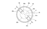
- FIG. 12 is a sectional view taken along line DD of FIG. 11. It is the right view which looked at the spool valve used for 4th Embodiment from the Y arrow line view of FIG.
- FIG. 14 is a sectional view taken along line EE of FIG. 13.
- valve timing control device for an internal combustion engine
- the valve timing control device according to the present embodiment is applied to the intake valve side, which is an engine valve.
- the valve timing control device can also be applied to the exhaust valve side.
- FIG. 1 is an overall configuration diagram of a valve timing control device for an internal combustion engine to which a solenoid valve according to the present invention is applied
- FIG. 2 is a sectional view taken along the line AA of FIG. 1 showing a lock mechanism used in the present embodiment. ..
- the valve timing control device includes a timing sprocket 1 (hereinafter referred to as a sprocket 1) that is a driving rotating body, and an intake-side cam that is provided so as to be rotatable relative to the sprocket 1.
- the shaft 2 the phase changing mechanism 3 for converting the relative rotational phase of the sprocket 1 and the cam shaft 2, the hydraulic circuit 4 for operating the phase changing mechanism 3, and the lock for locking the phase changing mechanism 3 at the most retarded phase position.
- the mechanism 5 is provided.
- the sprocket 1 has a disc-shaped sprocket body 1a, a gear portion 1b around which a timing chain is wound around the outer circumference of the sprocket body 1a, and a sprocket body 1a. It has a bearing hole (not shown) rotatably supported on the outer periphery of the one end 2a in the axial direction. Further, the sprocket body 1a has female screw holes formed at four positions in the circumferential direction of the outer peripheral portion at equal intervals in the circumferential direction.
- the sprocket 1 is designed so that the rotational force is transmitted from the crankshaft via the timing chain wound around the gear part 1b.
- the sprocket 1 is configured as a rear cover that liquid-tightly closes a rear end opening of a housing 6 described later.
- the drive rotating body may be a timing pulley in which the rotational force is transmitted by a timing belt.
- the camshaft 2 is rotatably supported on a cylinder head (not shown) via a plurality of cam bearings.
- the camshaft 2 is provided with a plurality of egg-shaped rotary cams on its outer periphery that open an intake valve (not shown) against the spring force of a valve spring.
- an insertion hole into which a cam bolt 13 to be described later is inserted, and an internal thread hole formed at the tip end side of the insertion hole and into which the cam bolt 13 is screwed are formed in the inner axial direction of one end of the cam shaft 2 in the rotation axis direction. And have.
- the phase changing mechanism 3 is fixed in the housing 6 in which a working chamber is formed inside, and axially fixed to one end of the camshaft 2 via a cam bolt described later, and is freely rotatable in the housing 6.
- the housing 6 is formed by press molding with a cylindrical housing body 11 integrally formed of a so-called sintered metal material formed by sintering powder metal, for example, and closes a front end opening of the housing body 11. It includes a front cover 12 (see FIG. 2) and a sprocket 1 (sprocket body 1a) as a rear cover that closes the rear end opening.
- the housing body 11 is formed in a substantially cylindrical shape, and a plurality of (four in the present embodiment) shoes 8 are provided at substantially equidistant positions on the inner peripheral surface in the circumferential direction.
- a plurality of (four in the present embodiment) shoes 8 are provided at substantially equidistant positions on the inner peripheral surface in the circumferential direction.
- four bolt insertion holes 11a into which four bolts 13a are inserted in the present embodiment are formed so as to penetrate therethrough along the axial direction.
- the front cover 12 has a relatively large insertion hole (not shown) formed therethrough at the center thereof. Further, the front cover 12 has the retard angle and the advance working chambers 9 and 10 depending on the side clearance between the insertion hole of the inner peripheral surface 12a and a portion except the outside of the insertion hole and one side surface of the vane rotor 7 facing each other. It is designed to seal the inside. Further, the front cover 12 is formed with four bolt insertion holes (not shown) through which the bolts 13a are inserted, at four locations in the circumferential direction of the outer peripheral portion.
- the sprocket 1, the housing main body 11, and the front cover 12 are jointly fastened together from the rotation axis direction by four bolts 13a which are inserted into the bolt insertion holes 11a and the like and screwed into the female screw portions of the sprocket 1.
- the vane rotor 7 is integrally formed of a sintered metal material like the housing body 11.
- the vane rotor 7 includes a rotor portion 14 located at the center and a plurality of (four in the present embodiment) vanes radially provided on the outer peripheral surface of the rotor portion 14 at substantially equal intervals of 90 ° in the circumferential direction. 15a to 15d.
- the rotor portion 14 is formed in a cylindrical shape having a relatively large diameter, and a bolt insertion hole 14a through which the cam bolt 13 is inserted is formed in the central axial direction of the rotor portion 14.
- the rotor portion 14 is fixed to one end portion of the cam shaft 2 by a cam bolt 13 having the bolt insertion hole 14a inserted therein.
- Each of the vanes 15a to 15d has a relatively short radial projection length and is arranged between the shoes 8. Further, the three second to fourth vanes 15b to 15d other than the one first vane 15a are set to have substantially the same circumferential width and are formed to be relatively thin. The first vane 15a has a large width in the circumferential direction, and a part of the lock mechanism 5 is provided inside.
- Sealing members 16a and 16b for sealing the inner peripheral surface of the housing body 11 and the outer peripheral surface of the rotor portion 14 are provided on the outer peripheral surfaces of the vanes 15a to 15d and the tips of the shoes 8, respectively. ..
- each of the retard working chambers 9 and each of the advancing working chambers 10 are hydraulic circuit 4 through four retard passages 17 and advance passage holes 18 which are formed in the rotor portion 14 in a substantially radial direction. It communicates with each.
- the lock mechanism 5 locks and holds the vane rotor 7 at the relative rotation position on the most retarded side with respect to the housing 6.
- the lock mechanism 5 includes a lock hole 19 formed by a hole forming portion 19 a at a predetermined position on the inner surface of the sprocket 1, and an internal axial direction of the first vane 15 a of the vane rotor 7.
- a pin accommodating hole 20 penetratingly formed in the hole, a lock pin 21 movably (movable forward and backward) in the pin accommodating hole 20 and having a truncated tip 21a inserted into and removed from the lock hole 19, and the lock.
- a coil spring 22 for urging the pin 21 toward the lock hole 19.
- the lock mechanism 5 is formed on the first releasing pressure receiving chamber 23 a formed in the lock hole 19, the step surface 21 b formed on the outer peripheral surface of the lock pin 21, and the inner peripheral surface of the pin accommodating hole 20. From the second release pressure receiving chamber 23b formed between the step portion 20a and the first and second lock passages 24a, 24b for supplying and discharging the hydraulic pressure to the first and second release pressure receiving chambers 23a, 23b. It is mainly composed.
- the lock hole 19 is formed in a conical shape having a diameter larger than the outer diameter of the tip portion 21a of the lock pin 21 via the hole forming portion 19a.
- the lock hole 19 is formed at a position corresponding to the rotation position of the vane rotor 7 on the innermost side of the sprocket body 1a on the most retarded side.
- the tip end surface of the tip portion 21a of the lock pin 21 receives the hydraulic pressure supplied to the first release pressure receiving chamber 23a or the second release pressure receiving chamber 23b. By these hydraulic pressures, the lock force is released from the lock hole 19 against the spring force of the coil spring 22, and the lock is released.
- Hydraulic pressure is supplied to the first releasing pressure receiving chamber 23a from one retarding working chamber 9 via the first lock passage 24a. Hydraulic pressure is supplied to the second releasing pressure receiving chamber 23b from one advance working chamber 10 via the second lock passage 24b.
- this lock position is the rotation position on the most retarded side of the vane rotor 7 with respect to the housing 6.
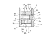
- the back pressure chamber 20b formed on the rear end side of the lock pin 21 communicates with the outside through the side end surface of the first vane 15a and the air vent holes 12b and 12c formed through the front cover 12. As a result, good slidability of the lock pin 21 is ensured.
- the hydraulic circuit 4 is provided in the axial direction of the rotor 14 and the oil pump 25 that discharges the working hydraulic pressure from the discharge passage 25a to a supply passage (not shown), depending on the engine operating state.
- the supply passage and the discharge passage 56 are provided with electromagnetic valves 26 that switch the flow paths of the retard passages 17 and the advance passages 18.
- the supply passage is formed in the bearing portion of the cylinder head or the cam shaft 2, the upstream portion communicates with the discharge passage 25a of the oil pump 25, and the downstream portion includes the retard angle passage holes 17 and the advance angle passage holes 18 respectively. Is in communication with.
- oil pump 25 a general type such as a vane type or a trochoid type is used.
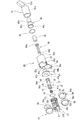
- FIG. 3 is an exploded perspective view of the solenoid valve used in the present embodiment
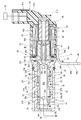
- FIG. 4 is a longitudinal sectional view of the solenoid valve showing a state in which the spool valve is moving to the maximum right direction
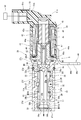
- FIG. 5 is a spool valve to the maximum left direction
- FIG. 6 is a vertical cross-sectional view of the solenoid valve showing a state in which the solenoid valve is moving.
- the solenoid valve 26 includes a cylindrical valve body 27 made of a metal material, for example, an aluminum alloy material, and a sliding body formed through the valve body 27 in the axial direction.
- the moving hole 27a, the spool valve 28 slidably arranged in the sliding hole 27a, the valve spring 29 for urging the spool valve 28 in the right direction shown in FIG. 4, and the spool valve 28 for the valve spring.
- It is mainly composed of a solenoid portion 30 that pushes to the left as shown in FIG. 5 against the spring force of 29.
- valve body 27 is housed in a cylindrical valve hole 01 formed in, for example, a cylinder block. Further, the valve body 27 is formed with drain holes 31a and 31b communicating with the discharge passage 56 at one end of the peripheral wall in the axial direction and the end wall 27b on the one end side.
- valve body 27 is provided with a supply port 32, which is an opening, a retard port 33, and an advance port 34, at substantially equidistant positions in the axial direction of the peripheral wall.
- the supply port 32 is arranged substantially at the center of the valve body 27 in the axial direction, and is formed so as to penetrate therethrough along the radial direction.
- the supply port 32 communicates with the discharge passage 25a of the oil pump 25.
- the retard port 33 is arranged on the side of the supply port 32 on the side of the solenoid 30 and is formed so as to penetrate therethrough in the radial direction.
- the retard port 33 communicates with the retard passage hole 17.
- the advance port 34 is arranged on the side portion on the end wall 27b side and is formed so as to penetrate therethrough in the radial direction.
- the advance port 34 communicates with the advance passage hole 18.
- the supply port 32, the retard port 33, and the advance port 34 have first to third groove grooves 32a, 33a, and 34a formed on the outer peripheral side, respectively.
- the first to third groove grooves 32a to 34a are formed by cutting the peripheral wall of the valve body 27 into an annular shape. Therefore, four annular protrusions 27d, 27e, 27f, and 27g are formed on both sides of each groove groove 32a to 34a.
- filtration filters 53, 54, 55 are attached to the annular bottom surfaces of the groove grooves 32a to 34a of the valve body 27, respectively.
- Each of the filtration filters 53 to 55 is formed by rolling a thin metal plate made of, for example, stainless steel into an annular shape, and a plurality of mesh holes 53a to 55a are formed in the inner portion excluding the outer peripheral portion. ..
- valve body 27 has an annular seal groove formed on the outer peripheral surface of the rear end of the peripheral wall on the solenoid 30 side.
- An oil seal 35 is fitted and fixed in the seal groove.
- the outer periphery of the oil seal 35 elastically contacts the inner peripheral surface of the valve hole 01 to seal between the outer peripheral surface of the valve body 27 and the inner peripheral surface of the valve hole 01.
- an annular holding groove is formed on the inner peripheral side of the outer end surface of the rear end portion 27c of the peripheral wall, and the seal ring 36 is fitted and fixed in the holding groove.
- the seal ring 36 is adapted to liquid-tightly seal a space S which is provided between the inner periphery of the rear end portion 27c of the valve body 27 and a holding member 47 of the solenoid portion 30 which will be described later.
- the space S faces the outer end surface 40a of the third land 40 of the spool valve 28, which will be described later. Therefore, the volume of the space S changes with the axial movement of the spool valve 28. .. That is, the spool valve 28 has a minimum volume at the maximum rightward moving position shown in FIG. 4, and has a maximum volume at the maximum leftward moving position shown in FIG.
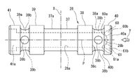
- FIG. 6 is a side view of the spool valve used in the present embodiment
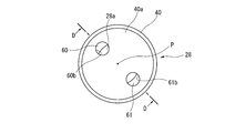
- FIG. 7 is a view taken in the direction of the arrow Y in FIG. 6
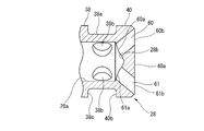
- FIG. 8 is a sectional view taken along line BB of FIG.
- the spool valve 28 is integrally formed of a metal material such as an aluminum alloy material. As shown in FIGS. 3 and 4 to 8, the spool valve 28 is formed in a cylindrical shape and has a substantially symmetrical shape about a radial line X (see FIG. 5) extending in a direction perpendicular to the center of the axis. Is formed in.
- the spool valve 28 has a drain passage 28a which is an oil passage communicating with the drain holes 31a and 31b of the valve body 27 in the inner axial direction.
- the drain passage 28a is linearly formed by drilling from the side of the fourth land portion 41 at one end portion in the axial direction of the spool valve 28 described later to the inside of the third land portion 40 at the other end portion. Further, the drain passage 28a is formed in a conical surface in which the bottom surface 28b of the other end portion on the side of the third land portion 40 is a machining mark of the drill tip.
- substantially symmetrical shape includes ones in which the shapes of the annular first to fourth lands 38 to 41 described later are different from each other.
- the spool valve 28 slides on the inner peripheral surface of the sliding hole 27a of the valve body 27 at both ends of the small-diameter shaft portion 37 located at the center in the axial direction to make the opening areas of the ports 32 to 34 variable. It has the cylindrical first and second land portions 38 and 39. Further, on the outer circumference of the small-diameter shaft portion 37, a cylindrical groove 37a which is long in the axial direction and forms a passage in cooperation with the inner circumferential surface of the sliding hole 27a is formed.
- first annular groove 38a and a second annular groove 39a are formed on the respective outer side portions of the first and second land portions 38, 39 in the axial direction.
- Each of the annular grooves 38a and 39a has an axial width shorter than that of the cylindrical groove 37a, but the depth is set to be substantially the same as that of the cylindrical groove 37a.
- each of the annular grooves 38a, 39a has a first communicating hole 38b and a second communicating hole 39b, which are radial oil passages for communicating the annular grooves 38a, 39a with the drain passage 28a. Are formed through.
- the first and second communication holes 38b and 39b are formed in a cross shape in the radial direction, and four holes are provided in each.
- the spool valve 28 integrally has annular third and fourth land portions 40 and 41 at the respective axial outer ends of the annular grooves 38a and 39a.
- the outer diameters of the third and fourth land portions 40 and 41 are set to be the same as those of the first and second land portions 38 and 39, and mainly the entire spool valve 28 slides on the inner peripheral surface of the sliding hole 27a. I will guide you.
- the first annular groove 38a has opposite side surfaces in the width direction formed by the annular outer surface 38c of the first land portion 38 and the annular inner surface 40b of the third land portion 40. Has been done.
- the opposing outer surface 38c and inner surface 40b have the same pressure receiving area.
- the third land portion 40 is disk-shaped and has a solid inside, and two first and second through holes 60 and 61 are formed through the inside.
- the first and second through holes 60 and 61 are set to have substantially the same passage cross-sectional area and extend from the axial center of the third land portion 40 in the radial direction. They are arranged symmetrically with respect to the straight line P. That is, the first and second through holes 60, 61 are formed in a slanted shape in a direction that expands outward at a predetermined angle, for example, about 45 ° with respect to the straight line P of the axis. This inclination angle is an angle orthogonal to the inclination angle of the bottom surface 28b of the drain passage 28a.
- the one end openings 60a and 61a open to the conical bottom surface 28b to face the drain passage 28a, and the other end openings 60b and 61b to the outer end surface 40a of the third land portion 40. It opens to and faces the space S. Since the first and second through holes 60 and 61 and the through holes 60 and 61 are formed in an inclined shape, the one end openings 60a and 61a and the other end openings 60b and 61b, respectively. When viewed from the axial center P direction of the drain passage 28a, it has an elliptical shape having a major axis in the radial direction from the axial center P side.
- the fourth land portion 41 is formed to have a substantially U-shaped vertical cross section, and a large-diameter columnar opening portion 41a that communicates the drain hole 31 and the drain passage 28a is formed inside.
- a valve spring 29 is held in a slightly compressed state between the bottom surface of the fourth land portion 41 and the bottom surface of the end wall 27b of the valve body 27. The valve spring 29 urges the spool valve 28 toward the solenoid portion 30 by the spring force.
- the solenoid portion 30 includes a cylindrical casing 42 made of a magnetic material, a cylindrical coil 43 fixed to the inner peripheral side of the casing 42 via a bobbin 43a, and a coil.
- a cylindrical portion 46 of a magnetic material, which is a fixed iron core, is provided on the inner circumferential side of 43 through a bottomed cylindrical core tube 45, and a magnetic material that is also a fixed iron core and is provided on the tip end side of the cylindrical portion 46
- a connector section 51 for supplying a control current output from a control unit (ECU) 50 to the coil 43.
- ECU control unit
- the casing 42 holds a shape by rolling a flat plate into a cylindrical shape and engaging an uneven portion (not shown) provided at the opposite end.
- the casing 42 is integrally provided with four claw portions 42 a that are fixed to the valve body 27 by caulking at one end edge in the axial direction.
- the other edge is also integrally provided with four claw portions 42b for crimping and fixing to a connector portion 51 described later.
- a connector portion 51 that is electrically connected to the ECU 50 via a harness is provided at the rear end portion of the casing 42.
- a magnetic material bracket 44 is welded and fixed to one end of the casing 42 on the valve body 27 side in the axial direction of the outer peripheral surface.
- the coil 43 is designed to be demagnetized by the control current supplied from the ECU 50.
- the bracket 44 is for fixing the entire solenoid valve 26 to the cylinder block, is integrally formed by press molding, and has a rectangular arc-shaped base portion 44a and a fixing arm integrally formed on the outer edge of the base portion 44a. 44b.
- the base 44a is fixed to the outer peripheral surface of the casing 42 by welding.
- the fixing arm 44b has a bolt insertion hole 44c penetratingly formed at a lower end portion thereof in the drawing, through which a bolt fixed to the cylinder block is inserted.
- the core tube 45 is formed of a stainless steel material into a thin-walled cylindrical shape, and its axial length is formed to cover the cylindrical portion 46 and a part of the holding member 47. Also, as shown in FIG. 3, the core tube 45 is formed in a stepped diameter shape, has a bottomed small diameter portion 45 a that covers the cylindrical portion 46, and is arranged on the valve body 27 side, and of the holding member 47. It is composed of a large diameter portion 45b that covers a part and a flange portion 45c that is integrally provided on the front end side of the large diameter portion 45b. Further, in the core tube 45, the inner peripheral surface of the flange portion 45c is in pressure contact with the front end surface of the bobbin 43a.
- the cylindrical portion 46 is fixed between the bobbin 43a and the small diameter portion 45a of the core tube 45, and applies a magnetic force to the plunger 48 that moves in the axial direction of the spool valve 28 as the coil 43 is energized. ing.
- the holding member 47 applies a magnetic force to the plunger 48 together with the cylindrical portion 46, and has a substantially cylindrical main body 47a and a flange portion 47b provided so as to face the front end portion of the main body 47a on the valve body 27 side. And have. Further, the holding member 47 is formed with a guide hole 47c penetratingly guiding the push rod 49 in the inner axial direction.
- the front end surface of the flange portion 47b elastically abuts the seal ring 36 held by the valve body 27 in the axial direction. As described above, the seal ring 36 also seals the space S and the inside of the guide hole 47c continuous to the space S.
- an oil seal 52 is sandwiched between the rear surface of the flange portion 47b and the flange portion 45c of the core tube 45.
- the oil seal 52 and the seal ring 36 seal the entire inside of the core tube 45.
- the plunger 48 has an air vent hole 48a formed therethrough for ensuring smooth movement in the direction of the inner axis.
- the push rod 49 has a disc portion 49a that is coupled to the plunger 48 at the rear end portion on the side of the plunger 48 in the axial direction. Further, the push rod 49 has a disk-shaped tip portion 49b having a small diameter, which is axially abutted on substantially the center of the outer end surface 40a of the third land portion 40 of the spool valve 28. Therefore, the tip end portion 49b of the push rod 49 is in a state where it does not overlap the other end opening portions 60b and 61b of the first and second through holes 60 and 61 at all.
- the push rod 49 pushes the spool valve 28 against the spring force of the valve spring 29 through the plunger 48 in the maximum leftward direction shown in FIG. 4 by exciting the holding member 47 and the cylindrical portion 46 by energizing the coil 43. It is designed to be moved.
- the connector portion 51 has a tubular base portion 51a fixed to the rear end portion of the casing 42, and a female connector 51b protruding from the rear end of the tubular base portion 51a. ing.
- One end of each of a pair of terminal pieces (not shown) embedded in the cylindrical base portion 51 a is connected to the coil 43.
- the other end portion 51c exposed to the outside of the terminal piece is connected to the terminal of the male connector on the control unit (ECU) 50 side.
- ECU control unit
- the ECU 50 is a cam whose internal computer detects a crank angle sensor (engine speed detection) (not shown), an air flow meter, an engine water temperature sensor, an engine temperature sensor, a throttle valve opening sensor, and a current rotation phase of the camshaft 2. Information signals from various sensors such as an angle sensor are input to detect the current engine operating state. This controls the drive of the engine. Further, as described above, the ECU 50 controls the moving position of the spool valve 28 by outputting the control current to the coil 43 or cutting off the energization to selectively switch the ports 32 to 34. There is.
- the solenoid section 30 moves the spool valve 28 to three positions in the front-rear axis direction by the control current of the ECU 50 and the relative pressure of the valve spring 29. That is, by continuously moving to three positions, the supply, retard angle, and advance ports 32, 33, 34 of the valve body 27 are relatively communicated or blocked. At the same time, the advance port 34 or the retard port 33 is made to communicate with the drain hole 31 and the drain passage 28a. Further, communication between the retard port 33 and the advance port 34 with respect to the supply port 32 is blocked. [Operation of the valve timing control device of the present embodiment] Hereinafter, the operation of the valve timing control device used in the present embodiment will be briefly described. When the engine is stopped, the oil pump 25 is also stopped, hydraulic oil is not supplied from the discharge passage 25a, and the ECU 50 transfers the coil 43 to the coil 43. It is not energized and is in a non-energized state.
- the spool valve 28 is held at the maximum rightward first position moving position by the spring force of the valve spring 29.
- the oil pump 25 is also driven to pump the hydraulic oil to the discharge passage 25a.
- the hydraulic oil flowing into the supply passage from the discharge passage 25a passes through the first groove groove 32a of the solenoid valve 26 and the first filtration filter 53 from the supply port 32 to the spool valve 28 as shown by the arrow in FIG. It flows into the cylindrical groove 37a. From there, the hydraulic oil flows into the retard port 33, passes through the second filtration filter 54, flows into the second groove groove 33a, and further from here into each retard passage hole 17 to perform each retard operation. It is supplied into the chamber 9. Therefore, the hydraulic pressure in each retard working chamber 9 rises.
- each advance angle working chamber 10 flows from the advance angle passage hole 18 through the third filtration filter 55 and each advance angle port 34 to the second communication hole 39b from the second annular groove 39a. From here, it flows into the drain passage 28 a and is discharged from the drain hole 31 into the oil pan OP. Therefore, each advance working chamber 10 is in a low pressure state.
- the vane rotor 7 is maintained at the most retarded relative rotation position. Therefore, the intake valve is in a state where the opening / closing timing is controlled to the retard side. This improves the startability of the engine.
- the same hydraulic pressure as that of the retarding working chamber 9 is supplied to the first releasing pressure receiving chamber 23a through the first lock passage 24a, but in the initial stage of cranking, the inside of the first releasing pressure receiving chamber 23a. Oil pressure does not rise. Therefore, as shown in FIG. 2, the lock pin 21 is in a state in which the front end portion 21a is inserted into the lock hole 19 and locked. Therefore, flapping of the vane rotor 7 due to the alternating torque generated in the camshaft 2 can be suppressed.
- the vane rotor 7 is held at an intermediate position between the most retarded angle and the most advanced angle, as shown in FIG. Therefore, the valve timing of the intake valve is controlled to an intermediate phase position between the most retarded angle and the most advanced angle. Therefore, for example, it is possible to stabilize the engine rotation and improve the fuel consumption during steady operation.
- the spool valve 28 moves further leftward against the spring force of the valve spring 29 and reaches the maximum leftward position, as shown in FIG.
- the first land portion 38 opens the retarded angle port 33 to allow the retarded angle port 33 to communicate with the first annular groove 38a and the first communication hole 38b.
- the second land portion 39 makes the supply port 32 communicate with the cylindrical groove 37 a and the advance port 34.
- each retard working chamber 9 flows from each retard passage hole 17 through the retard port 33 into the first annular groove 38a and the first communication hole 38b, and from there, the drain passage 28a. And it is quickly discharged into the oil pan OP through each drain hole 31.
- the hydraulic oil pumped from the oil pump 25 is supplied from the supply port 32 through the cylindrical groove 37a, the advancing port 34, and the filtration filter 55 to the advancing working chambers 10 through the advancing passage holes 18. ..
- the vane rotor 7 rotates clockwise from the position shown in FIG. 1 and relatively rotates toward the maximum advance side.
- the opening / closing timing of the intake valve becomes the most advanced phase, the valve overlap with the exhaust valve becomes large, the intake charging efficiency becomes high, and the output torque of the engine can be improved.
- the coil 43 of the solenoid valve 26 is energized to move the spool valve 28 leftward as shown in FIG. 5, and the third land portion 40 causes the retard port 33 and the first annular groove. 38a communicates. Then, the hydraulic oil in each retarded working chamber 9 flows from each retarded passage hole 17 through the retarded port 33 into the first annular groove 38a and the first communication hole 38b, and then into the drain passage 28a. ..
- the hydraulic pressure of the hydraulic oil in the retard port 33, the first annular groove 38a, and the first communication hole 38b increases.
- the first and second through holes 60 and 61 are formed in the third land portion 40 of the spool valve 28, it is possible to suppress an increase in hydraulic pressure in the space S via the drain passage 28a. it can.
- the hydraulic pressure is lower than the supplied hydraulic pressure but is relatively high. It was found that the hydraulic pressure was about 0.2 to 0.26 MPa. Further, the inside of the drain passage 28a is in a low pressure state because it communicates with the atmosphere.
- the relatively high hydraulic pressure in the first annular groove 38a flows into the space S from the gap between the outer peripheral surface of the third land portion 40 and the inner peripheral surface of the sliding hole 27a of the valve body 27. Then, the sealed space S is filled up. Therefore, the behavior of the spool valve 28 may become unstable due to the hydraulic pressure in the space S acting on the outer end surface 40a of the third land portion 40. This phenomenon occurs from the initial time point when the first land groove 38 opens the first annular groove 38a, and from this time point high hydraulic pressure acts on the first annular groove 38a.
- the low pressure drain passage 28a and the space portion S are in communication with each other.
- the internal pressure of the space S is in a low pressure state of about 0.1 MPa. Therefore, the high hydraulic pressure from the space S does not act on the outer end surface 40a of the third land portion 40.
- the hydraulic pressure flowing into the first annular groove 38a gives a force (load) for moving the spool valve 28 leftward in FIG. 5 to the outer side surface 38c, while a rightward direction opposite to this is applied to the inner side surface 40b.
- the through holes 60 and 61 also function as breathing holes. This also improves the axial mobility of the spool valve 28.
- the drain passage 28a and the space S are communicated with each other through the cutout groove.
- the pressure receiving area between the inner side surface 40b and the outer side surface 38c changes. That is, the pressure receiving area of the outer side surface 38c becomes larger than the pressure receiving area of the inner side surface 40b. Therefore, the behavior of the spool valve 28 is likely to be unstable.
- the inner diameters of the first and second through holes 60 and 61 are set to be relatively small, the behavior of the spool valve 28 becomes stable as compared with the case of using one large through hole.
- the time can be kept long. That is, when the through hole has one large inner diameter, the flow rate of the working oil flowing into the space S becomes large and the space S is immediately filled. Therefore, the time during which the behavior of the spool valve 28 can be stabilized may be shortened.
- the two through holes 60 and 61 and the respective inner diameters are reduced, so that the flow resistance is increased and the unit of the hydraulic oil flowing into the space S from the drain passage 28a is increased.
- the amount of hydraulic oil inflow decreases. Therefore, it is possible to prolong the time during which the behavior of the spool valve 28 is stable.
- first and second through holes 60, 61 are formed in an inclined shape from the center side of the third land portion 40 toward the outside, the accuracy of the passage cross-sectional area at the time of this drilling process is improved. Can be higher
- the drain passage 28a may be displaced (changed) due to the respective positions, inner diameters, and depths. There may be changes in the respective aperture areas for. This may reduce the accuracy of the passage cross-sectional area between the through holes 60 and 61.
- the through holes 60 and 61 in an inclined shape, the one end openings 60a and 61a of the through holes 60 and 61 are directed toward the axial center of the spool valve 28. Therefore, the change in cross-sectional area of each passage is reduced, and high accuracy can be secured.
- the tip end portion 49b is in contact with substantially the center of the outer end surface 40a of the third land portion 40, and the other end opening portions 60b of the first and second through holes 60 and 61 are formed. , 61b is not blocked even in part. Therefore, the passage cross-sectional areas of the through holes 60 and 61 are suppressed from being reduced, and the spool valve 28 can be stably moved.
- the push rod 49 is separately provided with a push rod. It is necessary to provide a member for abutting 49. For this reason, there is a risk that the design will be forced to be changed, the manufacturing operation will be complicated, and the cost will rise.
- first through hole 60 and the second through hole 61 are formed at symmetrical positions in the radial direction around the axis P, there is no influence on the weight balance of the spool valve 28.
- the overall mass of the spool valve 28 is reduced, and the inertial force is reduced in combination with the weight reduction of the aluminum material. Therefore, the response of the movement of the spool valve 28 is improved, and the control response of the valve timing is improved.
- both through holes 60 and 61 are formed at positions avoiding the first annular groove 38a and the first communication hole 38b, the fluidity of the hydraulic oil flowing through the first annular groove 38a and the like is improved. It has no effect.
- [Second Embodiment] 9 and 10 show a second embodiment of the present invention.
- the third land portion 40 of the spool valve 28 is provided with three first to third through holes 60, 61, 62.
- the first to third through holes 60 to 62 are each formed in an inclined shape extending outward from the conical bottom surface 28b of the drain passage 28a to the outer end surface 40a of the third land portion 40. .. Further, the through holes 60 to 62 are formed at substantially equal intervals in the circumferential direction of the third land portion 40. Further, the respective passage cross-sectional areas are set smaller than those of the through holes 60 and 61 of the first embodiment.
- the through holes 60 to 61 are formed at substantially equal intervals in the circumferential direction of the third land portion 40, the weight balance of the spool valve 28 is improved and the mass thereof is further reduced. As a result, the inertial force is further reduced and the movement response is improved.
- FIG. 11 and 12 show a third embodiment of the present invention.
- the two first and second through holes 60 and 61 are linearly provided along the inner axial direction of the third land portion 40.
- the first and second through holes 60 and 61 are drilled from the outer end surface 40a of the third land portion 40 to the drain passage 28a. That is, the through holes 60 and 61 are arranged between the outer end surface 40a of the third land portion 40 and the two first communication holes 38b, and do not hang on the first annular groove 38a, and thus the width direction of the first annular groove 38a. It extends linearly inside the one end. Then, the one end openings 60a, 61a have a part of their inner sides facing the drain passage 28a, and are not caught by any of the four first communication holes 38b, but between the two first communication holes 38b. It is arranged.
- each through hole 60, 61 is drilled linearly with a drill tool, the machining work is facilitated and the machining cost can be reduced.
- the drain passage 28a is not necessarily formed by drilling.
- the drain passage 28a can be formed together with the flat bottom surface 28b. It has become.
- the first and second through holes 60 and 61 are formed in an inclined shape from the flat bottom surface 28b toward the outside of the third land portion 40. Therefore, in each of the through holes 60 and 61, the one end openings 60a and 61a are opened to the bottom surface 28b, and the other end openings 60b and 61b are opened to the outer end surface 40a of the third land portion 40 to face the space S. I'm out.
- the same effects as those of the above-described embodiments can be obtained, and in the case where the spool valve 28 itself is formed by molding or the like, the through holes 60 and 61 are not formed. Molding work is also easy.
- the present invention is not limited to the configuration of each of the above-described embodiments, and for example, the passage cross-sectional area of each through hole 60 to 62 can be arbitrarily set according to the specifications and size of the solenoid valve.
- the inclination angles of the first and second through holes 60 and 61 are not fixed, and can be arbitrarily set at positions avoiding the first communication holes 38b and the like.
- the solenoid valve can also be applied to devices and equipment other than the valve timing control device. Further, this solenoid valve can be applied not only to the outside of the valve timing control device but to, for example, a cam bolt that fastens the vane rotor, which is the inside of the device, to the cam shaft.
- valve timing control device for an internal combustion engine using a timing sprocket is applied, but if it is applied to a valve timing control device using a timing pulley, the operational effect of the present invention becomes more remarkable.
- the solenoid valve having the following modes can be considered.
- a solenoid portion having a movable iron core that is axially driven by energizing a coil, a tubular valve body having a plurality of openings penetrating in a radial direction, and the valve body
- a spool valve that is disposed inside and that opens and closes each of the openings by moving in the axial direction by the movable iron core, is provided inside the spool valve, and has an oil passage communicating with atmospheric pressure and one end. It opens in the oil passage, and the other end opens in a space formed between one end of the spool valve on the movable iron core side and the solenoid, and surrounds the spool valve at one end around its axis.
- a spool valve having a plurality of through holes provided in the direction.
- the solenoid portion has a rod that is connected to the movable iron core and presses one end of the spool valve, and the plurality of through holes have a diameter larger than a contact surface of the rod with respect to the spool valve. It has on the outside of the direction.
- each of the through holes is arranged at a position avoiding the contact surface of the spool valve with the rod, the contact surface of the rod can be secured.
- the through hole is arranged on the contact surface of the spool valve, it is necessary to separately provide a member for contacting the rod with the spool valve, which necessitates a design change and complicates the manufacturing work. Therefore, there is a risk that the cost will rise sharply.
- the plurality of through holes are formed so as to be inclined radially outward from the axial center side of one end of the spool valve, and the other end side is more radially outward than the one end side.
- each through hole is formed so as to be inclined outward toward the solenoid portion side, it is possible to increase the accuracy of the opening area when drilling each through hole. .. That is, when each through hole is formed in a straight line along the axial direction of the spool valve, the opening area for the oil passage varies depending on the deviation (change) of the tolerance such as the position, the inner diameter, and the depth. Changes may occur. As a result, the accuracy of the opening area on the side of the drain passage of each through hole may decrease.
- each through hole in an inclined shape as in the present embodiment a change in each opening area is reduced, and high accuracy can be secured.
- two of the plurality of through holes are provided at a position facing one end of the spool valve with an axial center therebetween.
- the two weights are located at the positions that sandwich the axis of the spool valve, so the weight balance is good.
- three of the plurality of through holes are provided at predetermined intervals in the circumferential direction of one end of the spool valve.
- the oil passage is formed along the axial direction of the spool valve, has a conical surface at an end on the movable iron core side, and one end of each of the plurality of through holes opens in the conical surface. is doing.
- the opening area of one end does not change even if the axis of each through hole is slightly deviated. Therefore, the accuracy of the opening area is improved and the desired opening area can be secured.
- the spool valve has an annular groove on the outer periphery on the one end side, and a radial oil passage that connects the annular groove and the oil passage, and the plurality of through holes include the annular groove. And on the movable core side in the axial direction with respect to the radial oil passage.
- the positions of the through holes are separated from each other without overlapping the annular groove and the radial oil passage, so there is no effect on the space.
- the plurality of through holes are provided in an end wall provided at one end of the spool valve along the axial direction, and at least a part of each of the through holes is more than an inner peripheral surface of the oil passage. It is located radially outside.
- Each through hole is formed along the axial direction, so this drilling work is easy. Moreover, since a part of each of them is located radially outward of the inner peripheral surface of the oil passage, the opening area (passage cross-sectional area) of each through hole can be sufficiently secured.
- the spool valve has an annular groove on the outer periphery on the one end side, and a radial oil passage that connects the annular groove and the oil passage,
- the plurality of through holes are provided at positions displaced in the circumferential direction with respect to the radial oil passage.
- the multiple through holes are separated in the circumferential direction without overlapping the radial oil passage, there is no effect on the behavior of the spool valve. In addition, since they are separated not in the radial direction but in the circumferential direction, increase in size in the radial direction can be suppressed.
- the solenoid portion includes a fixed iron core having a flange portion sandwiched between the valve body and the coil, and the plurality of through holes are inclined outward in a radial direction from an axial center of the spool valve. Each of the openings at the other end faces the flange portion of the fixed core in the axial direction.
- the openings of the other ends of the plurality of through holes have an elliptical shape having a major axis in the radial direction from the axial center of the spool valve.
- the rotational force from the crankshaft is transmitted, and the driving rotary body having the working chamber inside is fixed to the camshaft while being relatively rotatably arranged inside the driving rotary body,
- a chamber is divided into a retarded working chamber and an advanced working chamber, and a driven rotating body that relatively rotates toward the advanced side or the advanced side with respect to the drive rotating body by supplying and discharging hydraulic oil to and from each working chamber.
- a valve timing control device for an internal combustion engine comprising: an electromagnetic valve that controls the supply and discharge of working oil pressure-fed from an oil pump to each working chamber
- the solenoid valve includes a solenoid portion having a movable iron core that is driven in the axial direction by energizing a coil, a valve body that is cylindrical and has a plurality of openings that penetrate in the radial direction, and an inside of the valve body.
- a spool valve that opens and closes each of the openings by moving in the axial direction by the movable iron core, the annular groove being provided on the outer periphery and communicating with the opening, and communicating with the annular groove, An oil passage communicating with atmospheric pressure inside, one end of which opens into the oil passage, and the other end of which opens into a space formed between one end of the spool valve on the movable iron core side and the solenoid portion.
- a spool valve having a plurality of through holes circumferentially provided around the axis of one end of the spool valve.
- SYMBOLS 1 Timing sprocket (driving body), 2 ... Cam shaft, 3 ... Phase change mechanism, 4 ... Hydraulic circuit, 5 ... Lock mechanism, 6 ... Housing, 7 ... Vane rotor, 8 ... Shoe, 9 ... Retarding working chamber, 10 ... Advance working chamber, 25 ... Oil pump, 26 ... Electromagnetic valve, 27 ... Valve body, 28 ... Spool valve, 28a ... Drain passage (oil passage), 28b ... Bottom surface (conical surface), 29 ... Valve spring, 30 ... Solenoid part, 32 ... Supply port (opening part), 33 ... Retard port (opening part), 34 ...
Landscapes
- Engineering & Computer Science (AREA)
- General Engineering & Computer Science (AREA)
- Mechanical Engineering (AREA)
- Valve Device For Special Equipments (AREA)
- Magnetically Actuated Valves (AREA)
Abstract
電磁弁26は、ソレノイド部30と、径方向に貫通する複数のポート32~34を有するバルブボディ27と、プランジャ48を介してバルブボディの内部を軸方向へ移動することで各ポートを開閉するスプール弁28と、を備えている。このスプール弁は、内部軸方向に大気圧と連通するドレン通路28aと、一端開口部60a、61aがドレン通路に開口し、他端開口部60b、61bがスプール弁の第3ランド部40の外端面40aと保持部材47との間に形成される空間部Sに開口し、スプール弁の第3ランド部の軸心を軸とした対称位置に設けられた2つの第1、第2貫通孔60,61と、を有している。 これらの構成によってスプール弁の挙動の不安定化を抑制することができる。
Description
本発明は、電磁弁と内燃機関のバルブタイミング制御装置に関する。
例えば、自動車の内燃機関のバルブタイミング制御装置に適用された電磁弁としては、以下の特許文献1に記載されたものが知られている。
この電磁弁は、筒状のバルブボディの外周にポートが径方向に沿って貫通形成されている。このポートは、バルブボディの軸方向に所定間隔で複数配置されていると共に、それぞれの外側開口端には環状溝が形成されている。また、前記バルブボディの内部には、前記各ポートの開閉を切り換える内部中空状のスプール弁が軸方向へ移動可能に設けられている。
このスプール弁は、内部軸心方向にドレン通路を有し、ソレノイド部側には円盤状の第1ランド部(ガイド壁)と第2ランド部及び該各ランド部を連結する小径な第1ステム部と、を有している。この第1ステム部には、前記ドレン通路に連通する第1通孔が径方向に沿って貫通形成されている。そして、前記一つのポートから第1ステム部に流れ込んだ作動油は、前記第1通孔を介してドレン通路に流入し、ここから外部のオイルパンに排出されるようになっている。
ところで、前記従来の電磁弁は、バルブボディの前記ポートからスプール弁の第1ステムの外周に流入した作動油の油圧(背圧)が比較的高くなっている。したがって、この背圧が、スプール弁の第1ランド部の外周面とバルブボディの内周面との隙間からソレノイド部側へリークして第1ランド部とソレノイド部の固定鉄心との間の空間部に流入してしまうおそれがある。このため、スプール弁は、前記空間部内の油圧上昇などの圧力変化によって挙動が不安定になるおそれがある。
本発明の一つの目的は、空間部内の油圧の上昇を抑えて、スプール弁の挙動の不安定化を抑制し得る電磁弁を提供することにある。
本発明の好ましい態様としては、とりわけ、径方向に貫通する複数の開口部を有するバルブボディの内部に配置され、可動鉄心によって軸方向へ移動することで前記各開口部を開閉するスプール弁であって、
このスプール弁は、内部に大気圧と連通する油通路と、一端が前記油通路に開口し、他端が前記スプール弁の前記可動鉄心側の一端部と前記ソレノイド部との間に形成される空間部に開口し、前記スプール弁の一端部の軸心周りの周方向位置に設けられた複数の貫通孔と、を有していることを特徴としている。
このスプール弁は、内部に大気圧と連通する油通路と、一端が前記油通路に開口し、他端が前記スプール弁の前記可動鉄心側の一端部と前記ソレノイド部との間に形成される空間部に開口し、前記スプール弁の一端部の軸心周りの周方向位置に設けられた複数の貫通孔と、を有していることを特徴としている。
本発明の好ましい態様によれば、スプール弁の挙動の不安定化を抑制することができる。
以下、本発明に係る電磁弁を内燃機関のバルブタイミング制御装置に適用した実施形態を図面に基づいて説明する。なお、本実施形態におけるバルブタイミング制御装置は、機関弁である吸気弁側に適用されている。なお、このバルブタイミング制御装置を排気弁側に適用することも可能である。
図1は本発明に係る電磁弁が適用された内燃機関のバルブタイミング制御装置の全体構成図、図2は本実施形態に供されるロック機構を示す図1のA-A線断面図である。
バルブタイミング制御装置は、図1及び図2に示すように、駆動回転体であるタイミングスプロケット1(以下、スプロケット1という。)と、スプロケット1に対して相対回転可能に設けられた吸気側のカムシャフト2と、スプロケット1とカムシャフト2の相対回転位相を変換する位相変更機構3と、位相変更機構3を作動させる油圧回路4と、該位相変更機構3を最遅角位相位置でロックさせるロック機構5と、を備えている。
スプロケット1は、円盤状に形成されたスプロケット本体1aと、このスプロケット本体1aの外周にタイミングチェーンが巻回される歯車部1bと、スプロケット本体1aの中央に貫通形成されて、カムシャフト2の回転軸方向の一端部2aの外周に回転自在に支持される図外の軸受孔とを有している。また、スプロケット本体1aは、外周部の円周方向の4箇所に雌ねじ孔が周方向の等間隔位置に形成されている。
スプロケット1は、歯車部1bに巻回されたタイミングチェーンを介してクランクシャフトから回転力が伝達されるようになっている。
また、このスプロケット1は、後述するハウジング6の後端開口を、液密的に閉塞するリアカバーとして構成されている。
なお、駆動回転体としては、タイミングベルトによって回転力が伝達されるタイミングプーリであっても良い。
カムシャフト2は、図外のシリンダヘッド上に複数のカム軸受を介して回転自在に支持されている。カムシャフト2は、外周に図外の吸気弁をバルブスプリングのばね力に抗して開作動させる複数の卵型の回転カムが設けられている。また、カムシャフト2の回転軸方向の一端部の内部軸心方向には、後述するカムボルト13が挿入される挿入孔と、この挿入孔の先端側に形成されてカムボルト13が螺着する雌ねじ孔と、を有している。
位相変更機構3は、図1に示すように、内部に作動室が形成されたハウジング6と、カムシャフト2の一端部に後述するカムボルトを介して軸方向から固定され、ハウジング6内に回転自在に収容されたベーンロータ7と、ハウジング6の作動室が仕切られたそれぞれ複数(本実施形態ではそれぞれ4つ)の第1作動室である遅角作動室9及び第2作動室進角作動室10と、を備えている。
ハウジング6は、例えば圧粉金属を焼結して成形されたいわゆる焼結金属材によって一体に形成された円筒状のハウジング本体11と、プレス成形によって形成され、ハウジング本体11の前端開口を閉塞するフロントカバー12(図2参照)と、後端開口を閉塞するリアカバーとしてのスプロケット1(スプロケット本体1a)と、から構成されている。
ハウジング本体11は、ほぼ円筒状に形成されて、内周面の周方向のほぼ等間隔位置に複数(本実施形態では4つ)のシュー8が突設されている。この各シュー8は、内部に、本実施形態では4本のボルト13aが挿入される4つのボルト挿入孔11aが軸方向に沿って貫通形成されている。
フロントカバー12は、中央に比較的大径な図外の挿入孔が貫通形成されている。また、フロントカバー12は、内周面12aの前記挿入孔及び該挿入孔よりも外側を除く部位とベーンロータ7の対向一側面との間のサイドクリアランスによって各遅角、進角作動室9,10内をシールするようになっている。また、フロントカバー12は、外周部の周方向4箇所に各ボルト13aが挿入される図外の4つのボルト挿通孔が貫通形成されている。
スプロケット1とハウジング本体11及びフロントカバー12は、各ボルト挿入孔11aなどに挿入してスプロケット1の各雌ねじ部に螺着する4本のボルト13aによって回転軸方向から共締め結合されている。
ベーンロータ7は、ハウジング本体11と同じく焼結金属材によって一体に形成されている。このベーンロータ7は、中央に位置するロータ部14と、該ロータ部14の外周面に円周方向のほぼ90°等間隔位置に放射状に突設された複数(本実施形態では4つ)のベーン15a~15dと、から構成されている。
ロータ部14は、比較的大径な円筒状に形成され、中央の内部軸方向にカムボルト13が挿入するボルト挿入孔14aが貫通形成されている。ロータ部14は、このボルト挿入孔14aを挿入したカムボルト13によってカムシャフト2の一端部に固定されている。
各ベーン15a~15dは、その径方向の突出長さが比較的短く形成されて、それぞれが各シュー8の間に配置されている。また、1つの第1ベーン15a以外の3つの第2~第4ベーン15b~15dは、円周方向の巾がほぼ同一に設定されて比較的薄肉に形成されている。第1ベーン15aは、周方向の幅が大きく形成されて、内部にロック機構5の一部が設けられている。
各ベーン15a~15dの外周面と各シュー8の先端には、それぞれハウジング本体11の内周面や、ロータ部14の外周面との間をシールするシール部材16a、16bがそれぞれ設けられている。
また、ベーンロータ7は、図1に示す位置から遅角側(反時計方向)へ相対回転すると、第1ベーン15aの一側面が対向する前記一つのシュー8の対向側面8aに当接して最大遅角側の回転位置が規制されるようになっている。また、進角側(時計方向)へ相対回転すると、同じく第1ベーン15aの他側面が対向する他のシュー8の対向側面8bに当接して最大進角側の回転位置が機械的に規制されるようになっている。
各ベーン15a~15dの正逆回転方向の両側面と各シュー8の両側面との間には、前述したそれぞれ4つの遅角作動室9と進角作動室10が設けられている。各遅角作動室9と各進角作動室10は、ロータ部14の内部にほぼ径方向に沿って形成されたそれぞれ4つの遅角通路孔17と進角通路孔18を介して油圧回路4にそれぞれに連通している。
ロック機構5は、ハウジング6に対してベーンロータ7を最遅角側の相対回転位置にロック保持するものである。
すなわち、ロック機構5は、図1及び図2に示すように、スプロケット1の内側面の所定位置に穴構成部19aによって形成されたロック穴19と、ベーンロータ7の第1ベーン15aの内部軸方向に貫通形成されたピン収容孔20と、該ピン収容孔20内に移動可能(進退動可能)に設けられ、截頭状の先端部21aがロック穴19に抜き差しするロックピン21と、該ロックピン21をロック穴19方向へ付勢するコイルスプリング22と、を備えている。
また、ロック機構5は、ロック穴19内に形成された第1解除用受圧室23aと、ロックピン21の外周面に形成された段差面21bとピン収容孔20の内周面に形成された段差部20aとの間に形成された第2解除用受圧室23bと、第1、第2解除用受圧室23a、23bに油圧を給排する第1,第2ロック通路24a、24bと、から主として構成されている。
ロック穴19は、穴構成部19aを介してロックピン21の先端部21aの外径よりも大径な円錐状に形成されている。また、ロック穴19は、スプロケット本体1aの内側面のベーンロータ7の最遅角側の回転位置に対応した位置に形成されている。
ロックピン21は、先端部21aの先端面が第1解除用受圧室23aか第2解除用受圧室23bに供給された油圧を受ける。これらの油圧によってコイルスプリング22のばね力に抗してロック穴19かから抜け出してロックが解除されるようになっている。
第1解除用受圧室23aには、第1ロック通路24aを介して一つの遅角作動室9から油圧が供給されるようになっている。第2解除用受圧室23bには、第2ロック通路24bを介して一つの進角作動室10から油圧が供給されるようになっている。
また、ロックピン21は、各受圧室23a、23bに油圧が供給されない場合は、コイルスプリング22のばね力によって先端部21aがロック穴19の内部に入り込む。これにより、ベーンロータ7をハウジング6に対してロックするようになっている。このロック位置は、前述したように、ハウジング6に対してベーンロータ7の最遅角側の回転位置となる。
なお、ロックピン21の後端側に形成された背圧室20bは、第1ベーン15aの側端面とフロントカバー12に貫通形成された空気抜き孔12b、12cを介して外部に連通している。これによって、ロックピン21の良好な摺動性を確保するようになっている。
油圧回路4は、図1に示すように、吐出通路25aから図外の供給通路に作動油圧を吐出するオイルポンプ25と、ロータ部14の内部軸方向に設けられて、機関運転状態に応じて供給通路と排出通路56に対して各遅角通路孔17と各進角通路孔18の流路を切り換える電磁弁26と、を備えている。
供給通路は、シリンダヘッドやカムシャフト2の軸受け部内に形成されて、上流部がオイルポンプ25の吐出通路25aと連通していると共に、下流側が各遅角通路孔17と各進角通路孔18に連通している。
オイルポンプ25は、一般的な例えばベーンタイプあるいはトロコイドタイプのものが用いられている。
図3は本実施形態に供される電磁弁の分解斜視図、図4はスプール弁が最大右方向に移動している状態を示す電磁弁の縦断面図、図5はスプール弁が最大左方向に移動している状態を示す電磁弁の縦断面図である。
電磁弁26は、図1、図3~図5に示すように、金属材である例えばアルミニウム合金材からなる円筒状のバルブボディ27と、該バルブボディ27の内部軸方向に貫通形成された摺動用孔27aと、この摺動用孔27a内に摺動可能に配置されたスプール弁28と、該スプール弁28を図4に示す右方向へ付勢するバルブスプリング29と、スプール弁28をバルブスプリング29のばね力に抗して図5に示す左方向へ押し出すソレノイド部30と、から主として構成されている。
バルブボディ27は、図4及び図5に示すように、例えばシリンダブロックに形成された円柱状の弁孔01内に収容配置されている。また、バルブボディ27は、周壁の軸方向の一端部及び該一端部側の端壁27bに排出通路56と連通するドレン孔31a、31bが形成されている。
また、バルブボディ27は、周壁の軸方向のほぼ等間隔位置にそれぞれ開口部である供給ポート32と、遅角ポート33及び進角ポート34が設けられている。
供給ポート32は、バルブボディ27の軸方向のほぼ中央位置に配置されて、径方向に沿って貫通形成されている。この供給ポート32は、オイルポンプ25の吐出通路25aに連通している。
遅角ポート33は、供給ポート32のソレノイド部30側の側部に配置され、径方向に沿って貫通形成されている。この遅角ポート33は、遅角通路孔17に連通している。
進角ポート34は、端壁27b側の側部に配置され、径方向に沿って貫通形成されている。この進角ポート34は、進角通路孔18に連通している。供給ポート32と遅角ポート33及び進角ポート34は、それぞれ外周側に第1~第3グルーブ溝32a、33a、34aが形成されている。
この第1~第3グルーブ溝32a~34aは、バルブボディ27の周壁をそれぞれ円環状に切り欠いて形成されている。したがって、各グルーブ溝32a~34aの両側には、4つの円環状の突起部27d、27e、27f、27gがそれぞれ形成されている。
なお、バルブボディ27の各グルーブ溝32a~34aの環状底面には、それぞれ濾過フィルタ53、54、55が装着されている。
この各濾過フィルタ53~55は、薄肉な例えばステンレス製の金属板材を丸めて円環状に形成されていると共に、外周部を除いた内側の部位に複数のメッシュ孔53a~55aが形成されている。
また、バルブボディ27は、周壁のソレノイド部30側の後端部の外周面に円環状のシール溝が形成されている。このシール溝には、オイルシール35が嵌着固定されている。このオイルシール35は、外周部が弁孔01の内周面に弾性的に当接してバルブボディ27の外周面と弁孔01の内周面との間をシールするようになっている。また、バルブボディ27は、周壁の後端部27cの外端面内周側に円環状の保持溝が形成されており、この保持溝にシールリング36が嵌着固定されている。このシールリング36は、バルブボディ27の後端部27c内周とソレノイド部30の後述する保持部材47との間に有する空間部Sを液密的にシールするようになっている。
この空間部Sは、後述するスプール弁28の第3ランド部40の外端面40aに面しており、したがって、スプール弁28の軸方向の移動に伴ってその体積が変化するようになっている。つまり、スプール弁28が、図4に示す最大右方向の移動位置では最小体積になっている一方、図5に示す最大左方向の移動位置では最大体積になる。
図6は本実施形態に供されるスプール弁の側面図、図7は図6のY矢視図、図8は図7のB-B線断面図である。
スプール弁28は、金属材である例えばアルミニウム合金材によって一体に形成されている。スプール弁28は、図3,図4~図8に示すように、円筒状に形成されて、軸線の中央を軸直角方向に延びる径方向線X(図5参照)を中心としてほぼ左右対称形状に形成されている。スプール弁28は、内部軸方向にバルブボディ27の各ドレン孔31a、31bと連通する油通路であるドレン通路28aが形成されている。このドレン通路28aは、後述するスプール弁28の軸方向の一端部に有する第4ランド部41側から他端部に有する第3ランド部40の内部までドリル加工によって直線状に形成されている。また、ドレン通路28aは、第3ランド部40側の他端部の底面28bがドリル先端の加工跡になった円錐面に形成されている。
なお、前述した「ほぼ対称形状」とは、後述する円環状の第1~第4ランド部38~41の形状が互いに異なっているものも含む。
このスプール弁28は、軸方向の中央に位置する小径軸部37の両端側にバルブボディ27の摺動用孔27aの内周面に摺動して前記各ポート32~34の開口面積を可変にする円筒状の第1、第2ランド部38,39を有している。また、小径軸部37の外周には、摺動用孔27aの内周面と協働して通路を構成する軸方向に長い筒状溝37aが形成されている。
さらに、第1、第2ランド部38,39の軸方向の各外側部には、第1環状溝38aと第2環状溝39aがそれぞれ形成されている。この各環状溝38a、39aは、軸方向幅が筒状溝37aよりも短く形成されているが、深さは筒状溝37aとほぼ同じに設定されている。
また、この各環状溝38a、39aの円環状の底壁には、該各環状溝38a、39aとドレン通路28aとを連通する径方向油路である第1連通孔38bと第2連通孔39bが貫通形成されている。この第1、第2連通孔38b、39bは、それぞれ径方向へ十字状に貫通形成されてそれぞれ4つ設けられている。
さらに、スプール弁28は、各環状溝38a、39aの軸方向の各外端部に円環状の第3、第4ランド部40、41を一体に有している。 この第3、第4ランド部40,41は、外径が第1、第2ランド部38,39と同一に設定されて、主としてスプール弁28全体を摺動用孔27aの内周面に摺動して案内するようになっている。
また、第1環状溝38aは、図6にも示すように、幅方向の対向両側面が、第1ランド部38の環状の外側面38cと第3ランド部40の環状の内側面40bによって構成されている。この対向する外側面38cと内側面40bは、同一の受圧面積になっている。
そして、第3ランド部40は、円盤状であって内部が中実状に形成されており、この内部に2つの第1、第2貫通孔60、61が貫通形成されている。
すなわち、第1、第2貫通孔60、61は、図4~図8に示すように、通路断面積がほぼ同一に設定されていると共に、第3ランド部40の軸心から径方向から延びる直線Pを中心とした対称位置に配置されている。つまり、第1、第2貫通孔60,61は、前記軸心の直線Pに対して所定角度、例えば約45°の角度で外側へ拡がる方向へ傾斜状に形成されている。この傾斜角度は、ドレン通路28aの底面28bの傾斜角度に直交する角度である。
また、各貫通孔60,61は、各一端開口部60a、61aが円錐状の底面28bに開口してドレン通路28aに臨み、他端開口部60b、61bが第3ランド部40の外端面40aに開口して空間部Sに臨んでいる。第1、第2貫通孔60、61は、また、各貫通孔60,61は、それぞれが傾斜状に形成されていることから、各一端開口部60a、61aと各他端開口部60b、61bがドレン通路28aの軸心P方向から視ると該軸心P側から径方向に長軸となる楕円形状になっている。
一方、第4ランド部41は、縦断面ほぼコ字形状に形成されていると共に、内部にドレン孔31とドレン通路28aを連通する大径円柱状の開口部41aが貫通形成されている。また、この第4ランド部41の底面とバルブボディ27の端壁27bの底面との間には、バルブスプリング29が僅かに圧縮状態で保持されている。このバルブスプリング29は、ばね力によってスプール弁28をソレノイド部30方向に付勢している。
ソレノイド部30は、図3~図5に示すように、磁性材からなる円筒状のケーシング42と、該ケーシング42の内周側にボビン43aを介して固定された円筒状のコイル43と、コイル43の内周側に有底円筒状のコアチューブ45を介して設けられた固定鉄心である磁性材の円筒部46と、該円筒部46の先端側に有する同じく固定鉄心である磁性材の保持部材47と、該保持部材47の内部に軸方向へ摺動可能な可動鉄心であるプランジャ48と、該プランジャ48のバルブボディ27側の先端部に固定部を介して固定されたプッシュロッド49と、コイル43にコントロールユニット(ECU)50から出力された制御電流を供給するコネクタ部51と、から主として構成されている。
ケーシング42は、平板を円筒状に丸めて対向端部に有する図外の凹凸部を係合させて形状保持している。また、ケーシング42は、図2に示すように、軸方向の一端縁にバルブボディ27に対してカシメ固定する4つの爪部42aが一体に設けられている。一方、他端縁にも、後述するコネクタ部51に対してカシメ固定する4つの爪部42bが一体に設けられている。ケーシング42の後端部には、ECU50にハーネスを介して電気的に接続されるコネクタ部51が設けられている。また、ケーシング42は、外周面の軸方向のバルブボディ27側の一端部に磁性材のブラケット44が溶接固定されている。
コイル43は、ECU50から通電された制御電流によって消励磁されるようになっている。
ブラケット44は、電磁弁26全体をシリンダブロックに固定するものであって、プレス成形によって一体に形成されて、矩形円弧状の基部44aと、該基部44aの外縁に一体に形成された固定用アーム44bと、から構成されている。基部44aは、溶接によってケーシング42の外周面に固定されている。固定用アーム44bは、図中下端部にシリンダブロックに固定されるボルトが挿通されるボルト挿通孔44cが貫通形成されている。
コアチューブ45は、ステンレス材によって薄肉円筒状に形成され、その軸方向の長さが円筒部46と保持部材47の一部を覆う長さに形成されている。また、コアチューブ45は、図3にも示すように、段差径状に形成されて、円筒部46を覆う有底状の小径部45aと、バルブボディ27側に配置されて、保持部材47の一部を覆う大径部45bと、該大径部45bの前端側に一体に設けられたフランジ部45cと、から構成されている。また、このコアチューブ45は、フランジ部45cの内周面がボビン43aの前端面に圧接している。
円筒部46は、ボビン43aとコアチューブ45の小径部45aとの間に固定されて、コイル43への通電に伴ってプランジャ48にスプール弁28の軸方向へ移動させる磁力を付与するようになっている。
保持部材47は、円筒部46と共にプランジャ48に磁力を付与するものであって、ほぼ円筒状の本体47aと、該本体47aのバルブボディ27側の前端部に対向して設けられたフランジ部47bと、を有している。また、保持部材47は、内部軸方向にプッシュロッド49を摺動案内するガイド孔47cが貫通形成されている。
フランジ部47bは、前端面がバルブボディ27に保持されたシールリング36に軸方向から弾性的に当接している。このシールリング36によって、前述のように、空間部Sと該空間部Sに連続するガイド孔47c内もシールされるようになっている。
また、フランジ部47bの背面とコアチューブ45のフランジ部45cとの間には、オイルシール52が挟み込まれた状態で配置されている。このオイルシール52とシールリング36とによって、コアチューブ45の内部全体がシールされている。
プランジャ48は、内部軸心方向に円滑な移動性を確保するための空気抜き孔48aが貫通形成されている。
プッシュロッド49は、軸方向のプランジャ48側の後端部に該プランジャ48と結合する円板部49aを有している。また、プッシュロッド49は、小径な円盤状の先端部49bがスプール弁28の第3ランド部40の外端面40aのほぼ中央に軸方向から当接している。したがって、プッシュロッド49の先端部49bは、第1、第2貫通孔60,61の各他端開口部60b、61bには全く掛からない状態になっている。
プッシュロッド49は、コイル43への通電による保持部材47や円筒部46への励磁によってプランジャ48を介してスプール弁28をバルブスプリング29のばね力に抗して図4に示す最大左方向へ押圧移動させるようになっている。
コネクタ部51は、図3~図5に示すように、ケーシング42の後端部に固定された筒状基部51aと、該筒状基部51aの後端から突出した雌コネクタ51bと、を有している。筒状基部51a内に埋設された一対の図外の端子片の各一端部が、コイル43に接続されている。一方、端子片の外部に露出した各他端部51cが、コントロールユニット(ECU)50側の雄コネクタの端子に接続されるようになっている。
ECU50は、内部のコンピュータが図外のクランク角センサ(機関回転数検出)やエアーフローメータ、機関水温センサ、機関温度センサ、スロットルバルブ開度センサおよびカムシャフト2の現在の回転位相を検出するカム角センサなどの各種センサ類からの情報信号を入力して現在の機関運転状態を検出する。これによって、機関の駆動を制御している。また、ECU50は、前述したように、コイル43に制御電流を出力、または通電を遮断してスプール弁28の移動位置を制御し、各ポート32~34を選択的に切換制御するようになっている。
すなわち、ソレノイド部30は、ECU50の制御電流とバルブスプリング29との相対的な圧力によって、スプール弁28を前後軸方向の3つのポジジョンに移動させる。つまり、3つのポジションに連続的に移動させることによってバルブボディ27の供給、遅角、進角ポート32、33、34を相対的に連通あるいは遮断させる。また同時に、進角ポート34あるいは遅角ポート33をドレン孔31とドレン通路28aに連通させる。さらに供給ポート32に対して遅角ポート33と進角ポート34との連通を遮断するようになっている。
〔本実施形態のバルブタイミング制御装置の作動〕
以下、本実施形態に供されるバルブタイミング制御装置の作動を簡単に説明する
機関停止状態になると、オイルポンプ25も停止されて吐出通路25aから作動油が供給されないと共に、ECU50からコイル43への通電もなく非通電状態となる。
〔本実施形態のバルブタイミング制御装置の作動〕
以下、本実施形態に供されるバルブタイミング制御装置の作動を簡単に説明する
機関停止状態になると、オイルポンプ25も停止されて吐出通路25aから作動油が供給されないと共に、ECU50からコイル43への通電もなく非通電状態となる。
したがって、スプール弁28は、図4に示すように、バルブスプリング29のばね力で最大右方向の第1ポジションの移動位置に保持されている。
次に、機関が始動を開始すると、オイルポンプ25も駆動して吐出通路25aに作動油を圧送する。吐出通路25aから供給通路内に流入した作動油は、図4中の矢印で示すように、電磁弁26の第1グルーブ溝32aと第1濾過フィルタ53を通って供給ポート32からスプール弁28の筒状溝37aに流入する。作動油は、ここから遅角ポート33に流入して第2濾過フィルタ54を通過して第2グルーブ溝33aに流入し、さらにここから各遅角通路孔17内に流入して各遅角作動室9内に供給される。したがって、各遅角作動室9内の油圧が上昇する。
同時に、スプール弁28は、進角ポート34を介して各進角通路孔18と第2環状溝39a及び第2連通孔39bを連通した状態になっている。したがって、各進角作動室10の作動油は、進角通路孔18から第3濾過フィルタ55と各進角ポート34を通って第2環状溝39aから第2連通孔39bに流入する。ここから、ドレン通路28aに流入してドレン孔31からオイルパンOP内に排出される。したがって、各進角作動室10が低圧状態になる。
このため、ベーンロータ7は、最遅角の相対回転位置に維持されている。したがって、吸気弁は、開閉タイミングが遅角側に制御された状態になる。これによって、機関の始動性が良好になる。
また、この時点では、第1ロック通路24aを介して第1解除用受圧室23aに遅角作動室9と同じ油圧が供給されるが、クランキング初期の時点では第1解除用受圧室23a内の油圧が上昇しない。このため、ロックピン21は、図2に示すように、先端部21aがロック穴19内に入り込んでロックされた状態となる。したがって、カムシャフト2に発生する交番トルクによるベーンロータ7のばたつきなどを抑制することできる。
その後、第1ロック通路24aを介して第1解除用受圧室23aに供給された油圧が高くなる。そうすると、ロックピン21が、コイルスプリング22のばね力に抗して後退移動してロック穴19とのロック状態が解除される。これによって、ベーンロータ7は、回転規制が解除されてフリーな状態になる。
次に、機関運転状態の変化に伴って、ECU50からコイル43への通電量が大きくなると、保持部材47などの励磁力が大きくなる。これにより、スプール弁28は、バルブスプリング29のばね力に抗してプランジャ48及びプッシュロッド49によって押し出されて、図4に示す状態から僅かに左方向へ移動する。
この状態では、第1ランド部38と第2ランド部39によって遅角ポート33と進角ポート34が塞がれて(閉止されて)、各遅角作動室9や各進角作動室10の作動油の供給あるいは排出が停止される。したがって、各遅角作動室9と各進角作動室10内に作動油が保持された状態になる。
これにより、ベーンロータ7は、図1に示すように、最遅角と最進角の間の中間位置に保持される。よって、吸気弁は、バルブタイミングが最遅角と最進角の間の中間位相位置に制御される。このため、例えば、定常運転時の機関回転の安定化と燃費の向上が図れる。
さらに、コイル43への通電量がさらに大きくなると、スプール弁28は、図5に示すように、バルブスプリング29のばね力に抗してさらに左方向へ移動して最大左方向の位置になる。この状態でのスプール弁28は、第1ランド部38が遅角ポート33を開いて、該遅角ポート33と第1環状溝38a及び第1連通孔38bを連通させる。と同時に、スプール弁28は、第2ランド部39が供給ポート32と筒状溝37a及び進角ポート34を連通させる。
このため、各遅角作動室9内の作動油は、各遅角通路孔17から遅角ポート33を通って第1環状溝38a、第1連通孔38bに流入し、ここから、ドレン通路28a及び各ドレン孔31を通って速やかにオイルパンOP内に排出される。
同時に、オイルポンプ25から圧送された作動油は、供給ポート32から筒状溝37a及び進角ポート34及び濾過フィルタ55を通って各進角通路孔18から各進角作動室10に供給される。
したがって、各遅角作動室9の内圧が低下する一方、各進角作動室10の内圧が上昇する。
よって、ベーンロータ7は、図1に示す位置から、時計方向へ回転して最大進角側へ相対回転する。これによって、吸気弁は、開閉タイミングが最進角位相になって排気弁とのバルブオーバーラップが大きくなり、吸気充填効率が高くなって機関の出力トルクの向上が図れる。
ここで、前述のように、電磁弁26のコイル43に通電されてスプール弁28が、図5に示すように左方向へ移動し、第3ランド部40によって遅角ポート33と第1環状溝38aが連通する。そうすると、各遅角作動室9内の作動油が、各遅角通路孔17から遅角ポート33を通って第1環状溝38aと第1連通孔38bに流入してドレン通路28a内に流入する。
このとき、遅角ポート33と第1環状溝38a及び第1連通孔38bの作動油の油圧が高くなる。しかし、スプール弁28の第3ランド部40に、第1、第2貫通孔60,61が形成されていることから、ドレン通路28aを介して空間部S内の油圧の上昇を抑制することができる。
すなわち、本願発明者の実験によって、遅角ポート33や第1環状溝38a及び第1連通孔38b内に流入した作動油の油圧の分布を解析すると、供給油圧よりは低いが比較的高く、例えば約0.2~0.26MPaの油圧になっていることがわかった。また、ドレン通路28a内は、大気に連通していることから低圧状態になっている。
したがって、従来では、第1環状溝38a内の比較的高い油圧が、第3ランド部40の外周面とバルブボディ27の摺動用孔27aの内周面との間の隙間から空間部Sに流入して、この密閉された空間部S内に充満してしまう。このため、スプール弁28は、空間部S内の油圧が第3ランド部40の外端面40aに作用することにより、挙動が不安定になるおそれがあった。この現象は、第1ランド部38によって第1環状溝38aが開かれた初期の時点から発生し、この時点から第1環状溝38aに高油圧が作用するからである。
これに対して、本実施形態では、第3ランド部40に第1、第2貫通孔60,61を設けることによって、低圧なドレン通路28aと空間部Sが連通状態になっている。これにより、第1環状溝38aに高い油圧が作用しても、空間部Sの内部圧力は、約0.1MPaの低圧状態になっている。このため、第3ランド部40の外端面40aには、空間部Sからの高い油圧が作用しなくなる。
また、第1ランド部38の外側面38cと第3ランド部40の内側面40bの受圧面積がほぼ同一になっていることから、第1環状溝38aに流入した作動油圧による軸方向の荷重が相殺される。
つまり、第1環状溝38aに流入した油圧は、外側面38cにスプール弁28を図5中、左方向へ移動させる力(荷重)を付与する一方、内側面40bにはこれと反対の右方向へ移動させる力(荷重)を付与する。これら両者38c、40bは、受圧面積がほぼ同一であるから前記相反する荷重が相殺されるのである。このため、スプール弁28は、前記軸方向荷重による影響が少なくなり、安定した保持性が確保される。
したがって、スプール弁28は、挙動の不安定化が十分に抑制されて安定かつ高精度な移動性を得ることができる。
この結果、各遅角作動室9と各進角作動室10への油圧の給排制御精度が高くなる。この結果、吸気弁のバルブタイミングの高い制御精度が得られる。
また、ドレン通路28aと空間部Sを各貫通孔60,61によって連通させることにより、各貫通孔60、61が呼吸孔としても機能する。これにより、スプール弁28の軸方向への移動性も良好になる。
なお、例えば、呼吸孔として第3ランド部40の外周縁に、軸方向に沿った切欠溝などを設けた場合には、この切欠溝を介してドレン通路28aと空間部Sを連通することになるが、前記内側面40bと外側面38cとの受圧面積が変化してしまう。つまり、外側面38cの受圧面積が、内側面40bの受圧面積よりも大きくなる。このため、スプール弁28の挙動が不安定になり易くなる。
また、第1、第2貫通孔60,61は、それぞれの内径が比較的小さく設定してあるため、一つの大径な貫通孔にした場合に比較して、スプール弁28の挙動の安定した時間を長く保持することができる。つまり、貫通孔を、一つの大径な内径とした場合には、空間部Sに流入する作動油の流量が大きくなって空間部S内に即座に充填されてしまう。このため、スプール弁28の挙動の安定化が図れる時間が短くなるおそれがある。
しかし、本実施形態のように、2つの貫通孔60,61でかつそれぞれの内径を小径化したことによって、流動抵抗が大きくなって、ドレン通路28aから空間部Sへ流入する作動油の単位当たりの作動油の流入量が少なくなる。このため、スプール弁28の挙動の安定した時間を長引かせることが可能になる。
また、第1、第2貫通孔60、61は、第3ランド部40の中央側から外側に向かって傾斜状に形成されていることから、この孔開け加工する際における通路断面積の精度を高くできる。
すなわち、各貫通孔60,61を、スプール弁28の軸方向に沿って直線状に形成した場合には、それぞれの位置や内径さらには深さなどの公差のずれ(変化)によって、ドレン通路28aに対するそれぞれの開口面積に変化が生じる可能性がある。これによって、各貫通孔60,61間の通路断面積の精度が低下するおそれがある。
しかし、本実施形態のように、各貫通孔60,61をそれぞれ傾斜状に形成することによって、各貫通孔60,61の各一端開口60a、61a側がスプール弁28の軸心に向かうようになっているため、それぞれの通路断面積の変化が少なくなり、高い精度を確保できる。
また、ソレノイド部30のプッシュロッド49は、先端部49bが第3ランド部40の外端面40aのほぼ中央に当接しており、第1、第2貫通孔60,61の各他端開口部60b、61bを一部でも塞ぐことがない。このため、各貫通孔60,61の通路断面積の減少化が抑制されて、スプール弁28の安定した移動性が可能になる。
換言すれば、例えば、プッシュロッド49の先端部49bが各貫通孔60,61の一部でも塞ぐように配置した場合には、この状態を回避するために、スプール弁28に、別途、プッシュロッド49を当接させる部材などを設けなければならない。このため、設計変更が余儀なくされて、製造作業が煩雑になり、コストの高騰を招くおそれがある。
しかし、本実施形態では、前述のような構成としたことから、製造作業が容易になると共に、コストの高騰を抑制できる。
さらに、第1貫通孔60と第2貫通孔61は、軸心Pを中心に径方向で対称位置に形成されていることから、スプール弁28の重量バランスに影響がない。
また、各貫通孔60,61を設けたことによって、スプール弁28は、全体の質量が小さくなるので、アルミ材質の軽量化と相俟って慣性力が低下する。このため、スプール弁28の移動の応答性が向上することから、バルブタイミングの制御応答性が良好になる。
また、両貫通孔60,61は、第1環状溝38aと第1連通孔38bに掛からず避けた位置に形成されていることから、第1環状溝38aなどを流通する作動油の流動性に影響を与えることがない。
〔第2実施形態〕
図9及び図10は本発明の第2実施形態を示している。この第2実施形態では、スプール弁28の第3ランド部40に3つの第1~第3貫通孔60,61,62を設けたものである。
〔第2実施形態〕
図9及び図10は本発明の第2実施形態を示している。この第2実施形態では、スプール弁28の第3ランド部40に3つの第1~第3貫通孔60,61,62を設けたものである。
第1~第3貫通孔60~62は、第1実施形態と同じくそれぞれドレン通路28aの円錐状の底面28bから第3ランド部40の外端面40aまで外側に向かった傾斜状に形成されている。また、各貫通孔60~62は、第3ランド部40の円周方向のほぼ等間隔位置に形成されている。また、それぞれの通路断面積は、第1実施形態の貫通孔60,61よりも小さく設定されている。
他の構成は第1実施形態と同じである。
したがって、この実施形態も空間部S内の低圧化によってスプール弁28の挙動の不安定化を抑制できるなど、第1実施形態と同様な作用効果が得られる。
また、各貫通孔60~61は、第3ランド部40の円周方向のほぼ等間隔位置に形成されていることから、スプール弁28の重量バランスが良好になると共に、質量がさらに小さくなる。この結果、慣性力がさらに低減して移動応答性が向上する。
〔第3実施形態〕
図11及び図12は本発明の第3実施形態を示している。この第3実施形態では、2つの第1、第2貫通孔60,61を、第3ランド部40の内部軸方向に沿って直線状に設けたものである。
〔第3実施形態〕
図11及び図12は本発明の第3実施形態を示している。この第3実施形態では、2つの第1、第2貫通孔60,61を、第3ランド部40の内部軸方向に沿って直線状に設けたものである。
第1、第2貫通孔60、61は、第3ランド部40の外端面40aからドレン通路28aまでドリル加工によって孔開けされている。つまり、各貫通孔60、61は、第3ランド部40の外端面40aから2つの第1連通孔38bの間に配置され、第1環状溝38aに掛かることなく第1環状溝38aの幅方向一端部の内側まで直線状に延びている。そして、各一端開口部60a、61aは、内側の一部がドレン通路28aに臨んでいると共に、4つの第1連通孔38bのいずれにも掛かることなく、2つの第1連通孔38bの間に配置されている。
したがって、この第3実施形態によれば、前記各実施形態と同様な作用効果が得られる。
また、各貫通孔60,61を、ドリル工具によって直線状に孔開け加工したことから、加工作業が容易になり、加工コストの低減化が図れる。
また、各貫通孔60,61は、第1環状溝38aや第1連通孔38bを避けた位置に設けられていることから、作動油の流通性に影響を与えることなく、スプール弁28の挙動の安定化を維持できる。
〔第4実施形態〕
図13及び図14は本発明の第4実施形態を示している。この第4実施形態は、基本構造は第1実施形態と同じであるが、ドレン通路28aの底面28bが円錐状ではなく平坦状に形成されている。
〔第4実施形態〕
図13及び図14は本発明の第4実施形態を示している。この第4実施形態は、基本構造は第1実施形態と同じであるが、ドレン通路28aの底面28bが円錐状ではなく平坦状に形成されている。
つまり、ドレン通路28aは、必ずしもドリル加工だけではなく、例えば、スプール弁28自体を焼結金属などの型成形で成形した場合には、ドレン通路28aも一緒に型成形できるので底面28bが平坦状になっている。
第1、第2貫通孔60,61は、平坦な底面28bから第3ランド部40の外側に向かって傾斜状に形成されている。したがって、各貫通孔60,61は、各一端開口部60a、61aが底面28bに開口し、他端開口部60b、61bが第3ランド部40の外端面40aに開口して空間部Sに臨んでいる。
よって、この第3実施形態によれば、前記各実施形態と同じ作用効果が得られることは勿論のこと、スプール弁28自体を型成形などによって成形する場合には、各貫通孔60,61の成形作業も容易になる。
本発明は、前記各実施形態の構成に限定されるものではなく、例えば、各貫通孔60~62の通路断面積を電磁弁の仕様や大きさなどによって任意に設定することができる。
また、第1、第2貫通孔60,61の傾斜角度は固定的なものではなく、各第1連通孔38bなどを避けた位置に任意に設定することが可能である。
前記電磁弁は、バルブタイミング制御装置以外の装置や機器類に適用することも可能である。また、この電磁弁は、必ずしもバルブタイミング制御装置の外側ではなく、例えば、装置の内側であるベーンロータをカムシャフトに締結するカムボルトに適用することも可能である。
また、各実施形態では、タイミングスプロケットを用いた内燃機関のバルブタイミング制御装置に適用したが、タイミングプーリを用いたものに適用すれば本発明の作用効果がさらに顕著になる。
つまり、タイミングプーリを用いた場合は、電磁弁などから作動油が外部にリークしないように電磁弁の内部が液密的にシールされている。このため、空間部の液密性も高くなるので、前述したスプール弁の挙動の不安定化といった技術的課題を招き易い。
これに対して、本発明は空間部を低圧化することから、前記技術的課題を効果的に解決することが可能になる。
以上説明した実施形態に基づく電磁弁としては、例えば、以下に述べる態様のものが考えられる。
その一つの態様として、コイルへの通電によって軸方向へ駆動される可動鉄心を有するソレノイド部と、筒状であって、径方向に貫通する複数の開口部を有するバルブボディと、前記バルブボディの内部に配置され、前記可動鉄心によって軸方向へ移動することで前記各開口部を開閉するスプール弁であって、前記スプール弁の内部に設けられて、大気圧と連通する油通路と、一端が前記油通路に開口し、他端が前記スプール弁の前記可動鉄心側の一端部と前記ソレノイド部との間に形成される空間部に開口し、前記スプール弁の一端部の軸心周りに周方向に設けられた複数の貫通孔と、を有するスプール弁と、を備えている。
さらに好ましくは、前記ソレノイド部は、前記可動鉄心に連結されて前記スプール弁の一端部を押圧するロッドを有し、前記複数の貫通孔は、前記ロッドの前記スプール弁に対する当接面よりも径方向の外側に有している。
この発明の態様によれば、前記各貫通孔は、前記スプール弁におけるロッドとの当接面を避けた位置に配置されているので、ロッドの当接面を確保できる。例えば、貫通孔をスプール弁の当接面に配置した場合には、スプール弁に、別途、ロッドを当接させる部材を設ける必要があることから、設計変更が余儀なくされて、製造作業が煩雑になり、コストの高騰を招くおそれがある。
さらに好ましくは、前記複数の貫通孔は、スプール弁の一端部の軸心側から径方向外側へ傾斜状に形成されて、前記他端側が一端側よりも径方向外側に有している。
この発明の態様によれば、各貫通孔を、ソレノイド部側に向かって外側へ傾斜状に形成したことによって、この各貫通孔を孔開け加工する際における開口面積の精度を高くすることができる。すなわち、各貫通孔を、スプール弁の軸方向に沿って直線状に形成した場合には、それぞれの位置や内径さらには深さなどの公差のずれ(変化)によって油通路に対するそれぞれの開口面積に変化が生じる場合がある。これによって、各貫通孔のドレン通を側の開口面積の精度が低下するおそれがある。しかし、本実施形態のように、各貫通孔をそれぞれ傾斜状に形成することによって、それぞれの開口面積の変化が少なくなり、高い精度を確保できる。
さらに好ましくは、前記複数の貫通孔は、前記スプール弁の一端部に軸心を挟んで対向した位置に2つ設けられている。
スプール弁の軸心を挟んだ位置に2つ設けられていることから、重量のバランスが良い。
さらに好ましくは、前記複数の貫通孔は、前記スプール弁の一端部の周方向へ所定の間隔位置に3つ設けられている。
貫通孔を、周方向へほぼ等間隔位置に3つ設けたことから重量のバランスが良い。
さらに好ましくは、前記油通路は、前記スプール弁の軸方向に沿って形成され、前記可動鉄心側の端部に円錐面を有し、前記複数の貫通孔は、一端部が前記円錐面に開口している。
この発明の態様によれば、傾斜状の各貫通孔を孔開け加工する際に、この各貫通孔の軸心が多少ずれても一端部の開口面積の変化がない。よって、開口面積の精度が良好になり所望の開口面積を確保できる。
さらに好ましくは、前記スプール弁は、前記一端部側の外周に環状溝を有すると共に、この環状溝と前記油通路を連通する径方向油路を有し、前記複数の貫通孔は、前記環状溝と前記径方向油路よりも軸方向の前記可動鉄心側に設けられている。
複数の貫通孔の位置が、環状溝と径方向油路には重なることがなく離れているので、空間部への影響がない。
さらに好ましくは、前記複数の貫通孔は、スプール弁の一端部に有する端壁に軸方向に沿って設けられ、前記各貫通孔のそれぞれの少なくとも一部が、前記油通路の内周面よりも径方向外側に位置している。
各貫通孔が、軸方向に沿って形成されることによって、この孔開け加工作業が容易である。また、それぞれの一部が、油通路の内周面より径方向外側に位置していることから、各貫通孔の開口面積(通路断面積)を十分に確保できる。
さらに好ましくは、前記スプール弁は、前記一端部側の外周に環状溝を有すると共に、この環状溝と前記油通路を連通する径方向油路を有し、
前記複数の貫通孔は、前記径方向油路に対して周方向へずれた位置に設けられている。
前記複数の貫通孔は、前記径方向油路に対して周方向へずれた位置に設けられている。
複数の貫通孔が、径方向油路に重なることなく周方向へ離れていることから、スプール弁の挙動への影響がない。また、径方向ではなく周方向へ離れていることから、径方向の大型化が抑制できる。
さらに好ましくは、前記ソレノイド部は、前記バルブボディと前記コイルとの間に挟まれるフランジ部を有する固定鉄心を備え、前記複数の貫通孔は、スプール弁の軸心から径方向外側に向かって傾斜状に形成されて、それぞれの前記他端の開口が軸方向において前記固定鉄心のフランジ部に対向している。
さらに好ましくは、前記複数の貫通孔は、前記他端の開口がスプール弁の軸心から径方向に長軸を有する楕円形状になっている。
別の好ましい態様としては、クランクシャフトからの回転力が伝達され、内部に作動室を有する駆動回転体と、前記駆動回転体の内部に相対回転可能に配置されつつカムシャフトに固定され、前記作動室を遅角作動室と進角作動室に分け、前記各作動室に作動油が給排されることで前記駆動回転体に対して進角側あるいは進角側へ相対回転する従動回転体と、オイルポンプから圧送された作動油を前記各作動室に給排制御する電磁弁と、を備えた内燃機関のバルブタイミング制御装置であって、
前記電磁弁は、コイルへの通電によって軸方向へ駆動される可動鉄心を有するソレノイド部と、筒状であって、径方向に貫通する複数の開口部を有するバルブボディと、前記バルブボディの内部に配置され、前記可動鉄心によって軸方向へ移動することで前記各開口部を開閉するスプール弁であって、外周に設けられて前記開口部に連通する環状溝と、前記環状溝に連通し、内部に大気圧と連通する油通路と、一端が前記油通路に開口し、他端が前記スプール弁の前記可動鉄心側の一端部と前記ソレノイド部との間に形成される空間部に開口し、前記スプール弁の一端部の軸心周りに周方向に設けられた複数の貫通孔と、を有するスプール弁と、を備えている。
前記電磁弁は、コイルへの通電によって軸方向へ駆動される可動鉄心を有するソレノイド部と、筒状であって、径方向に貫通する複数の開口部を有するバルブボディと、前記バルブボディの内部に配置され、前記可動鉄心によって軸方向へ移動することで前記各開口部を開閉するスプール弁であって、外周に設けられて前記開口部に連通する環状溝と、前記環状溝に連通し、内部に大気圧と連通する油通路と、一端が前記油通路に開口し、他端が前記スプール弁の前記可動鉄心側の一端部と前記ソレノイド部との間に形成される空間部に開口し、前記スプール弁の一端部の軸心周りに周方向に設けられた複数の貫通孔と、を有するスプール弁と、を備えている。
1…タイミングスプロケット(駆動回転体)、2…カムシャフト、3…位相変更機構、4…油圧回路、5…ロック機構、6…ハウジング、7…ベーンロータ、8…シュー、9…遅角作動室、10…進角作動室、25…オイルポンプ、26…電磁弁、27…バルブボディ、28…スプール弁、28a…ドレン通路(油通路)、28b…底面(円錐面)、29…バルブスプリング、30…ソレノイド部、32…供給ポート(開口部)、33…遅角ポート(開口部)、34…進角ポート(開口部)、32a~34a…グルーブ溝、38…第1ランド部、38a…第1環状溝、38b…第1連通孔(径方向油路)、39…第2ランド部、39a…第2環状溝、39b…第2連通孔、40…第3ランド部(端壁)、40a…外端面、41…第4ランド部、43…コイル、46…円筒部(固定鉄心)、47…保持部材(固定鉄心)、48…プランジャ(可動鉄心)、49…プッシュロッド(ロッド)、60…第1貫通孔、60a…一端開口部、60b…他端開口部、61…第2貫通孔、61a…一端開口部、61b…他端開口部、62…第3貫通孔、62a一端開口部、62b…他端開口部、S…空間部
Claims (12)
- コイルへの通電によって軸方向へ駆動される可動鉄心を有するソレノイド部と、
筒状であって、径方向に貫通する複数の開口部を有するバルブボディと、
前記バルブボディの内部に配置され、前記可動鉄心によって軸方向へ移動することで前記各開口部を開閉するスプール弁であって、前記スプール弁の内部に設けられて、大気圧と連通する油通路と、一端が前記油通路に開口し、他端が前記スプール弁の前記可動鉄心側の一端部と前記ソレノイド部との間に形成される空間部に開口し、前記スプール弁の一端部の軸心周りの周方向位置に設けられた複数の貫通孔と、を有するスプール弁と、
を備えたことを特徴とする電磁弁。 - 請求項1に記載の電磁弁において、
前記ソレノイド部は、前記可動鉄心に連結されて前記スプール弁の一端部を押圧するロッドを有し、
前記複数の貫通孔は、前記ロッドの前記スプール弁に対する当接面よりも径方向の外側に有することを特徴とする電磁弁。 - 請求項2に記載の電磁弁において、
前記複数の貫通孔は、スプール弁の一端部の軸心側から径方向外側へ傾斜状に形成されて、前記他端側が一端側よりも径方向外側に有することを特徴とする電磁弁。 - 請求項3に記載の電磁弁において、
前記複数の貫通孔は、前記スプール弁の一端部に軸心を挟んで対向した位置に2つ設けられていることを特徴とする電磁弁。 - 請求項3に記載の電磁弁において、
前記複数の貫通孔は、前記スプール弁の一端部の周方向へ所定の間隔位置に3つ設けられたことを特徴とする電磁弁。 - 請求項3に記載の電磁弁において、
前記油通路は、前記スプール弁の軸方向に沿って形成され、前記可動鉄心側の端部に円錐面を有し、
前記複数の貫通孔は、一端部が前記円錐面に開口していることを特徴とする電磁弁。 - 請求項2に記載の電磁弁において、
前記スプール弁は、前記一端部側の外周に環状溝を有すると共に、この環状溝と前記油通路を連通する径方向油路を有し、
前記複数の貫通孔は、前記環状溝と前記径方向油路よりも軸方向の前記可動鉄心側に設けられていることを特徴とする電磁弁。 - 請求項2に記載の電磁弁において、
前記複数の貫通孔は、スプール弁の一端部に有する端壁に軸方向に沿って設けられ、前記各貫通孔のそれぞれの少なくとも一部が、前記油通路の内周面よりも径方向外側に位置していることを特徴とする電磁弁。 - 請求項2に記載の電磁弁において、
前記スプール弁は、前記一端部側の外周に環状溝を有すると共に、この環状溝と前記油通路を連通する径方向油路を有し、
前記複数の貫通孔は、前記径方向油路に対して周方向へずれた位置に設けられていることを特徴とする電磁弁。 - 請求項2に記載の電磁弁において、
前記ソレノイド部は、前記バルブボディと前記コイルとの間に挟まれるフランジ部を有する固定鉄心を備え、
前記複数の貫通孔は、スプール弁の軸心から径方向外側に向かって傾斜状に形成されて、それぞれの前記他端の開口が軸方向において前記固定鉄心のフランジ部に対向することを特徴とする電磁弁。 - 請求項10に記載の電磁弁において、
前記複数の貫通孔は、前記他端の開口がスプール弁の軸心から径方向に長軸を有する楕円形状になっていることを特徴とする電磁弁。 - クランクシャフトからの回転力が伝達され、内部に作動室を有する駆動回転体と、
前記駆動回転体の内部に相対回転可能に配置されつつカムシャフトに固定され、前記作動室を遅角作動室と進角作動室に分け、前記各作動室に作動油が給排されることで前記駆動回転体に対して進角側あるいは進角側へ相対回転する従動回転体と、
オイルポンプから圧送された作動油を前記各作動室に給排制御する電磁弁と、
を備えた内燃機関のバルブタイミング制御装置であって、
前記電磁弁は、
コイルへの通電によって軸方向へ駆動される可動鉄心を有するソレノイド部と、
筒状であって、径方向に貫通する複数の開口部を有するバルブボディと、
前記バルブボディの内部に配置され、前記可動鉄心によって軸方向へ移動することで前記各開口部を開閉するスプール弁であって、外周に設けられて前記開口部に連通する環状溝と、前記環状溝に連通し、内部に大気圧と連通する油通路と、一端が前記油通路に開口し、他端が前記スプール弁の前記可動鉄心側の一端部と前記ソレノイド部との間に形成される空間部に開口し、前記スプール弁の一端部の軸心周りの周方向位置に設けられた複数の貫通孔と、を有するスプール弁と、
を備えたことを特徴とする内燃機関のバルブタイミング制御装置。
Priority Applications (1)
| Application Number | Priority Date | Filing Date | Title |
|---|---|---|---|
| JP2020555959A JP7068495B2 (ja) | 2018-11-16 | 2019-10-25 | 電磁弁と内燃機関のバルブタイミング制御装置 |
Applications Claiming Priority (2)
| Application Number | Priority Date | Filing Date | Title |
|---|---|---|---|
| JP2018215127 | 2018-11-16 | ||
| JP2018-215127 | 2018-11-16 |
Publications (1)
| Publication Number | Publication Date |
|---|---|
| WO2020100556A1 true WO2020100556A1 (ja) | 2020-05-22 |
Family
ID=70731985
Family Applications (1)
| Application Number | Title | Priority Date | Filing Date |
|---|---|---|---|
| PCT/JP2019/041954 Ceased WO2020100556A1 (ja) | 2018-11-16 | 2019-10-25 | 電磁弁と内燃機関のバルブタイミング制御装置 |
Country Status (2)
| Country | Link |
|---|---|
| JP (1) | JP7068495B2 (ja) |
| WO (1) | WO2020100556A1 (ja) |
Citations (3)
| Publication number | Priority date | Publication date | Assignee | Title |
|---|---|---|---|---|
| JP2001182565A (ja) * | 1999-12-22 | 2001-07-06 | Honda Motor Co Ltd | 内燃機関の動弁制御装置 |
| JP2013077792A (ja) * | 2011-09-15 | 2013-04-25 | Denso Corp | 電磁アクチュエータ |
| JP2017003041A (ja) * | 2015-06-12 | 2017-01-05 | 日立オートモティブシステムズ株式会社 | 油圧制御弁及び内燃機関のバルブタイミング制御装置 |
-
2019
- 2019-10-25 WO PCT/JP2019/041954 patent/WO2020100556A1/ja not_active Ceased
- 2019-10-25 JP JP2020555959A patent/JP7068495B2/ja active Active
Patent Citations (3)
| Publication number | Priority date | Publication date | Assignee | Title |
|---|---|---|---|---|
| JP2001182565A (ja) * | 1999-12-22 | 2001-07-06 | Honda Motor Co Ltd | 内燃機関の動弁制御装置 |
| JP2013077792A (ja) * | 2011-09-15 | 2013-04-25 | Denso Corp | 電磁アクチュエータ |
| JP2017003041A (ja) * | 2015-06-12 | 2017-01-05 | 日立オートモティブシステムズ株式会社 | 油圧制御弁及び内燃機関のバルブタイミング制御装置 |
Also Published As
| Publication number | Publication date |
|---|---|
| JP7068495B2 (ja) | 2022-05-16 |
| JPWO2020100556A1 (ja) | 2021-09-24 |
Similar Documents
| Publication | Publication Date | Title |
|---|---|---|
| JP6373464B2 (ja) | 内燃機関のバルブタイミング制御装置 | |
| JP7157826B2 (ja) | 内燃機関のバルブタイミング制御装置に用いられる制御弁及び内燃機関のバルブタイミング制御システム | |
| JP5713823B2 (ja) | バルブタイミング制御装置に用いられる制御弁 | |
| US9689285B2 (en) | Solenoid valve for variable valve timing control devices, and variable valve timing control system | |
| JP6295160B2 (ja) | 電磁弁と、内燃機関のバルブタイミング制御装置に用いられる電磁弁並びに電磁アクチュエータ | |
| JPWO2016021328A1 (ja) | 油圧制御弁及び該油圧制御弁が用いられた内燃機関のバルブタイミング制御装置 | |
| JP2019007515A (ja) | 油圧制御弁 | |
| JP2018059415A (ja) | 油圧制御弁及び内燃機関のバルブタイミング制御装置 | |
| CN103726895B (zh) | 内燃机的气门正时控制装置 | |
| JP6581475B2 (ja) | 電磁弁 | |
| JP7068495B2 (ja) | 電磁弁と内燃機関のバルブタイミング制御装置 | |
| JP6775032B2 (ja) | 油圧制御弁及び内燃機関のバルブタイミング制御装置 | |
| JP7064922B2 (ja) | 内燃機関のバルブタイミング制御装置及び内燃機関のバルブタイミング制御装置に用いられる制御弁 | |
| JP2019124292A (ja) | 電磁アクチュエータ及び該電磁アクチュエータを用いた内燃機関のバルブタイミング制御装置 | |
| JP6704823B2 (ja) | 内燃機関のバルブタイミング制御装置の油圧制御弁及び内燃機関のバルブタイミング制御装置 | |
| JP2020186662A (ja) | 内燃機関のバルブタイミング制御装置 | |
| JP2019007516A (ja) | 油圧制御弁とバルブタイミング制御装置。 | |
| JP6290068B2 (ja) | 油圧制御弁及び該油圧制御弁が用いられた内燃機関のバルブタイミング制御装置 | |
| JP4000127B2 (ja) | 内燃機関のバルブタイミング制御装置 | |
| JP2020193583A (ja) | 内燃機関のバルブタイミング制御装置 | |
| JP6492201B2 (ja) | 内燃機関のバルブタイミング制御装置に用いられる油圧制御弁 | |
| WO2023037738A1 (ja) | 内燃機関のバルブタイミング制御装置 | |
| WO2019049810A1 (ja) | 油圧制御弁と内燃機関のバルブタイミング制御装置 | |
| JP2019074046A (ja) | 内燃機関のバルブタイミング制御装置と、内燃機関のバルブタイミング制御装置に用いられる油圧制御弁。 | |
| JP2022139762A (ja) | 油圧制御弁および内燃機関のバルブタイミング制御装置 |
Legal Events
| Date | Code | Title | Description |
|---|---|---|---|
| 121 | Ep: the epo has been informed by wipo that ep was designated in this application |
Ref document number: 19883756 Country of ref document: EP Kind code of ref document: A1 |
|
| ENP | Entry into the national phase |
Ref document number: 2020555959 Country of ref document: JP Kind code of ref document: A |
|
| NENP | Non-entry into the national phase |
Ref country code: DE |
|
| 122 | Ep: pct application non-entry in european phase |
Ref document number: 19883756 Country of ref document: EP Kind code of ref document: A1 |