WO2020100388A1 - 接合部材および接合構造 - Google Patents
接合部材および接合構造 Download PDFInfo
- Publication number
- WO2020100388A1 WO2020100388A1 PCT/JP2019/035147 JP2019035147W WO2020100388A1 WO 2020100388 A1 WO2020100388 A1 WO 2020100388A1 JP 2019035147 W JP2019035147 W JP 2019035147W WO 2020100388 A1 WO2020100388 A1 WO 2020100388A1
- Authority
- WO
- WIPO (PCT)
- Prior art keywords
- contact surface
- contact
- rear end
- end surface
- joining
- Prior art date
- Legal status (The legal status is an assumption and is not a legal conclusion. Google has not performed a legal analysis and makes no representation as to the accuracy of the status listed.)
- Ceased
Links
Images










Classifications
-
- E—FIXED CONSTRUCTIONS
- E04—BUILDING
- E04B—GENERAL BUILDING CONSTRUCTIONS; WALLS, e.g. PARTITIONS; ROOFS; FLOORS; CEILINGS; INSULATION OR OTHER PROTECTION OF BUILDINGS
- E04B1/00—Constructions in general; Structures which are not restricted either to walls, e.g. partitions, or floors or ceilings or roofs
- E04B1/18—Structures comprising elongated load-supporting parts, e.g. columns, girders, skeletons
- E04B1/24—Structures comprising elongated load-supporting parts, e.g. columns, girders, skeletons the supporting parts consisting of metal
-
- E—FIXED CONSTRUCTIONS
- E04—BUILDING
- E04B—GENERAL BUILDING CONSTRUCTIONS; WALLS, e.g. PARTITIONS; ROOFS; FLOORS; CEILINGS; INSULATION OR OTHER PROTECTION OF BUILDINGS
- E04B1/00—Constructions in general; Structures which are not restricted either to walls, e.g. partitions, or floors or ceilings or roofs
- E04B1/38—Connections for building structures in general
- E04B1/58—Connections for building structures in general of bar-shaped building elements
Definitions
- the present invention relates to a joining member and a joining structure.
- the beam end joint formed between the member and the member to be joined is generally designed as a rigid joint or a pin joint.
- the flange of the steel girder is welded or bolted to the steel girder, and the web of the steel girder is bolted to the steel girder.
- the web of the steel beam is bolted to the shear plate attached to the steel beam, and the flange of the steel beam is not connected to the steel beam.
- Non-Patent Document 1 can be applied under load conditions in which the moment of the joint does not reverse, such as a gravity frame that does not bear a horizontal force and a moment frame when the horizontal force is small and anti-symmetric bending is not performed. Bonding using contact plates is described. The contact plate is inserted in the gap between the small end surface of the lower flange of the steel beam which is the member to be joined and the support member, and transmits the force of the compression side flange of the steel beam to the opposing support member.
- EUROPEAN COMMITTEE FOR STANDARDIZATION ⁇ Eurocode 4: Design of Composite Composite Steel and Concrete Structures Part 1-8: Design of joints, May 2005
- the contact region between at least one of the joined member and the supporting member is linear or narrow with respect to the flange plate thickness.
- the contact area is extremely small with respect to the cross-sectional area of the flange, so that the stress in the bearing portion corresponding to the compressive force increases and plastic deformation occurs. Therefore, in this case, it is difficult to stabilize the rigidity and proof stress against the compression force F.
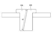
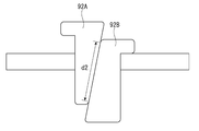
- the joining members 92A and 92B are two-piece members each having an inclined surface facing each other as shown in FIGS. 18A and 18B, the contact area becomes wider than that in the example of FIG. 17, but as shown in the drawing.
- the size of the contact area (shown as the dimensions d1 and d2 in the cross section) fluctuates with respect to the size variation of the gap.
- An object is to provide a new and improved joining member and joining structure.
- a joining member that includes a first member and a second member and that transmits a compressive force between a joined member and a supporting member.
- the first member includes a first rear end surface that is in contact with an end surface of the members to be joined in the material axis direction, and a contact surface that is formed on the opposite side of the first rear end surface with an inclination with respect to the first rear end surface.
- the second member includes a second rear end surface that is in contact with a surface of the support member that faces the end surface of the member to be joined, and an inclined surface with respect to the second rear end surface on the side opposite to the second rear end surface.
- the contact surface of the first member and the contact surface of the second member are in contact with each other, the contact surface of the first member including the contact surface having a dimension different from the contact surface of the first member in a vertical cross section including the material axis direction of the members to be joined. To do.
- the first member may further include a protruding portion that protrudes from the first rear end surface toward the member to be joined.
- the second member may further include a protrusion that protrudes from the second rear end surface toward the support member.
- the first rear end face may be in surface contact with the end face of the joined member. Further, the second rear end surface may be in surface contact with the surface of the support member.
- the size in the direction orthogonal to the inclination in the contact surface of the first member and the size in the direction orthogonal to the inclination in the contact surface of the second member may be different from each other. Further, when viewed in the material axis direction of the members to be joined, the direction of inclination of the contact surface of the first member may have an angle with respect to the direction of inclination of the contact surface of the second member.
- the contact surface of the first member is formed parallel to the first contact surface and the first contact surface and recedes toward the first rear end surface side with respect to the first contact surface.
- a second contact surface of the second member the contact surface of the second member being parallel to the third contact surface and the third contact surface whose dimension in the vertical cross section is larger than that of the first contact surface.
- the fourth contact surface including a fourth contact surface that is formed to advance to the side opposite to the second rear end surface and has a dimension in the vertical cross section that is smaller than the second contact surface, and the first contact surface and the third contact surface are The second contact surface and the fourth contact surface may contact each other, and may contact each other.
- the first member may further include a protrusion that is located on the side opposite to the first contact surface in the vertical cross section, adjacent to the second contact surface, and protrudes from the second contact surface.
- the first member is located adjacent to the second contact surface on the side opposite to the first contact surface in the vertical cross section, and is parallel to the first contact surface and the second contact surface
- the second member further includes a fifth contact surface formed by advancing to a side opposite to the first rear end surface with respect to the second contact surface, and the second member has a fourth contact surface on a side opposite to the third contact surface in a vertical cross section. Is located adjacent to, is parallel to the third contact surface and the fourth contact surface, is formed to recede toward the second rear end surface side with respect to the fourth contact surface, and has a dimension in the vertical cross section of the fifth.
- the fifth contact surface may further include a sixth contact surface larger than the contact surface, and the fifth contact surface and the sixth contact surface may contact each other.
- the inclination angle ⁇ and the static friction coefficient ⁇ between the first member and the second member may satisfy the relationship of tan ⁇ ⁇ ⁇ .
- the first member may have a uniform cross-sectional shape orthogonal to both the contact surface of the first member and the first rear end surface.
- the second member may have a uniform cross-sectional shape orthogonal to both the contact surface and the second rear end surface of the second member.
- a joining structure including a member to be joined, a support member, and the above-mentioned joining member inserted in a gap between an end surface of the member to be joined and a surface of the support member. It In a horizontal cross section including the material axis direction, the end surface of the member to be joined and the surface of the support member may be nonparallel.
- the above-described joining structure includes concrete and a reinforcing bar embedded in the concrete, and further includes an RC floor slab arranged above the joined member and the supporting member, and the joined members are arranged on both sides of the supporting member, respectively.
- the RC floor slab is disposed above the first H-shaped cross-section beam, the second H-shaped cross-section beam and the support member and includes a pair of joining members respectively inserted into the first H-section cross-section beam.
- the top flange and the top flange of the second H-section beam may be joined to the RC floor slab using a shear connector.
- the member to be joined is the first H-shaped cross-section beam
- the end surface of the member to be joined is the end face in the material axis direction of the lower flange of the first H-shaped cross-section beam
- the support member is the second member.
- the surface of the support member is the end face in the width direction of the lower flange of the second H-section beam, and the cross-sectional height of the first H-section beam and the second H-section beam May be equal.
- the first member and the second member can slide with respect to each other in the direction inclined by the angle ⁇ with respect to the vertical direction while maintaining the contact of the contact surfaces.
- the sliding distance between the first member and the second member is L
- the distance between the first rear end face of the first member and the second rear end face of the second member changes by Lsin ⁇ . Therefore, the joining member can be inserted in the gap between the members whose dimensions vary.
- the contact area between the first contact surface and the third contact surface is It is constant depending on the dimension of the first contact surface, and the contact area between the second contact surface and the fourth contact surface is also constant depending on the dimension of the fourth contact surface. Therefore, in the joining member, it is possible to secure a contact area having a constant size regardless of the size of the gap between the members.
- FIG. 3 is a sectional view taken along line III-III in FIG. 2. It is a figure for demonstrating operation
- FIG. It is a figure which shows another example of the joining structure which concerns on the 1st Embodiment of this invention. It is a figure which shows another example of the joining structure which concerns on the 1st Embodiment of this invention. It is a figure which shows another example of the joining structure which concerns on the 1st Embodiment of this invention. It is a figure which shows another example of the joining structure which concerns on the 1st Embodiment of this invention.
- FIG. 9 is a sectional view taken along line IX-IX in FIG. 8. It is a perspective view of the joining structure which concerns on the 3rd Embodiment of this invention.
- FIG. 11 is a sectional view taken along line XI-XI of FIG. 10.
- 3 is a cross-sectional view showing the dimensions of each part in Embodiment 1.
- FIG. 7 is a cross-sectional view showing the dimensions of each part in the second embodiment.
- FIG. 9 is a cross-sectional view showing the dimensions of each part in the third embodiment.
- FIG. 9 is a cross-sectional view showing the dimensions of each part in the fourth embodiment.
- FIG. 13 is a cross-sectional view showing the dimensions of each part in the fifth embodiment. It is a graph which shows the relationship between the nominal compressive stress and the compressive strain calculated in the Example. It is a figure which shows the dimension of the joining structure in an Example. It is a graph which shows the relationship between the moment calculated in an example, and a rotation angle. It is a graph which shows the examination result regarding an inclination angle. It is a figure which shows the example of the conventional joining member. It is a figure which shows another example of the conventional joining member. It is a figure which shows another example of the conventional joining member.
- FIG. 1 is a diagram showing a joining structure according to a first embodiment of the present invention.
- the joining structure includes a beam 1 which is a member to be joined, a shear plate 31 and a flange connecting plate 32 which are support members joined to the girder 2, an RC floor slab (or a composite deck slab) 5.
- a joining member 10 More specifically, the beam 1 is an H-shaped cross-section beam including an upper flange 1A, a lower flange 1B, and a web 1C.
- the girder 2 is a support-side H-shaped cross-section beam that extends in a direction orthogonal to the material axis direction of the girder 1 and includes an upper flange 2A, a lower flange 2B, and a web 2C.
- the shear plate 31 is a plate-shaped member orthogonal to the girder 2, and is arranged on at least one side of the web 2C and welded to the upper flange 2A, the lower flange 2B, and the web 2C.
- the flange connecting plate 32 is a plate-shaped member parallel to the upper flange 2A and the lower flange 2B of the girder 2, and is welded to the web 2C and the shear plate 31.
- the end surface 32E of the flange connecting plate 32 faces the end surface 1E of the lower flange 1B in the material axis direction of the beam 1.
- the RC floor slab 5 includes concrete 51, a reinforcing bar 52 embedded in the concrete 51, a deck plate 53, and a shear connector 54.
- the upper flange 1A of the beam 1 and the upper flange 2A of the girder 2 are shear connectors 54. Is joined to the RC floor slab 5 via.
- the joining member 10 is inserted in the gap g between the end face 1E of the lower flange 1B of the beam 1 in the material axis direction and the end face 32E of the flange connecting plate 32 facing the end face 1E, and is connected to the beam 1 and the flange.
- the compressive force is transmitted to and from the plate 32.
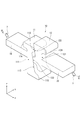
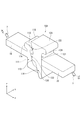
- FIG. 2 is an enlarged perspective view showing the joining member 10 shown in FIG. 1, and FIG. 3 is a sectional view taken along line III-III of FIG.
- the joining member 10 includes a first member 11 and a second member 12, and transmits the compressive force F between the lower flange 1B of the beam 1 and the flange connecting plate 32 as described above. ..
- the transmission direction of the compressive force F (x direction in the figure) coincides with the material axis direction of the beam 11.
- the first member 11 includes a first rear end surface 111, a first contact surface 112, a second contact surface 113, a first protrusion 114, and a second protrusion 115.
- the first contact surface 112, the second contact surface 113, and the second protruding portion 115 are formed on the side opposite to the first rear end surface 111, and the first protruding portion 114 is formed on the same side as the first rear end surface 111.
- the second member 12 includes a second rear end surface 121, a third contact surface 122, a fourth contact surface 123, and a third protrusion 124.
- the third contact surface 122 and the fourth contact surface 123 are formed on the side opposite to the second rear end surface 121, and the third protrusion 124 is formed on the same side as the second rear end surface 121.
- the first member 11 has a shape of a cross section (xz cross section in the drawing) orthogonal to both the contact surface (the first contact surface 112 and the second contact surface 113) and the first rear end surface 111. It is uniform.
- the second member 12 also has a uniform cross-section (xz cross-section in the drawing) orthogonal to both the contact surface (the third contact surface 122 and the fourth contact surface) and the second rear end surface 121. ..
- the first rear end surface 111 of the first member 11 included in the joining member 10 is brought into contact with the end surface 1E of the lower flange 1B of the beam 1. It
- the end surface 1E is an end surface of the beam 1 in the material axis direction.
- the first rear end surface 111 is also formed perpendicular to the material axis direction of the beam 1. As a result, the first rear end surface 111 makes surface contact with the end surface 1E.
- the first contact surface 112 of the first member 11 is formed with an angle ⁇ (0 ⁇ ⁇ 90 °) with respect to the first rear end surface 111, as shown in FIG.
- the plane P (yz plane) shown in FIG. 3 is parallel to the first rear end surface 111.
- the second contact surface 113 is parallel to the first contact surface 112, and is formed so as to recede toward the first rear end surface 111 side with respect to the first contact surface 112. That is, as illustrated, in the state where the first member 11 and the second member 12 are opposed to each other, the second contact surface 113 is farther from the second member 12 than the first contact surface 112. ..
- the second rear end surface 121 of the second member 12 is in contact with the end surface 32E of the flange connecting plate 32 in the assembled state of the joint structure.
- the second rear end surface 121 is also formed perpendicular to the material axis direction of the beam 1.
- the second rear end face 121 makes surface contact with the end face 32E.
- the third contact surface 122 of the second member 12 is formed to be inclined with respect to the second rear end surface 121 by an angle ⁇ , as shown in FIG. It The plane P shown in FIG. 3 is also parallel to the second rear end face 121.
- the fourth contact surface 123 is parallel to the third contact surface 122, and is formed by advancing to the side opposite to the second rear end surface 121 with respect to the third contact surface 122. That is, as illustrated, in the state where the first member 11 and the second member 12 are opposed to each other, the fourth contact surface 123 is closer to the first member 11 than the third contact surface 122. ..
- the first member 11 and the second member 12 have a width (length in the y direction in the drawing) that can be accommodated between the web 1C of the beam 1 and the widthwise end of the lower flange 1B. Have).
- the width of the first member 11 and the second member 12 is not limited to this example, and the width of the gap g, the member to be joined (the beam 1 in the illustrated example), and the support member (the girder in the illustrated example). In each case, it is appropriately determined depending on the cross-sectional shape of 2) so that the state of being stably inserted in the gap g can be maintained.
- the first contact surface 112 of the first member 11 and the third contact surface 122 of the second member 12 contact each other, and the second contact surface 113 of the first member 11 and the second member Twelve fourth contact surfaces 123 contact each other.
- the dimension d 3 of the third contact surface 122 is larger than the dimension d 1 of the first contact surface 112 in the vertical cross section including the axial direction of the beam 1 and the fourth contact
- the dimension d 4 of the surface 123 is smaller than the dimension d 2 of the second contact surface 113.
- the joining member 10 has a gap between members whose dimensions change, specifically, a gap g (see FIG. 1) between the end face 1E of the lower flange 1B of the beam 1 and the end face 32E of the flange connecting plate 32. Can be inserted.
- the first member 11 and the second member 12 slide with respect to each other due to the size relationship (specifically, d 3 > d 1 and d 4 ⁇ d 2 ) of the dimensions of the contact surfaces as described above. Even if it moves, the contact area between the first contact surface 112 and the third contact surface 122 is constant depending on the dimension d 1 of the first contact surface 112, and the second contact surface 113 and the fourth contact surface 112. The contact area with 123 is also constant depending on the dimension d 4 of the fourth contact surface 123. Therefore, in the joining member 10, the size of the gap between the members is constant regardless of the size of the gap g between the end face 1E of the lower flange 1B of the beam 1 and the end face 32E of the flange connecting plate 32. A large contact area can be secured. As a result, the compressive force F can be stably transmitted between the beam 11 and the flange connecting plate 32.
- the first protruding portion 114 that protrudes from the first rear end surface 111 to the beam 1 side is formed in the first member 11, and the second member 12 extends from the second rear end surface 121 to the flange connecting plate 32.
- a third protrusion 124 that protrudes to the side is formed. The first projecting portion 114 and the third projecting portion 124 project from positions corresponding to the upper ends of the first rear end surface 111 and the second rear end surface 121, for example, in a state where the joining structure is assembled as shown in the drawing.
- the respective dimensions of the first member 11 and the second member 12 become larger in the material axis direction of the beam 1 (x direction in the drawing), so that the first member 11 or the second member 12 moves from the gap g. It can be prevented from falling off and the construction becomes easy. If such a function is not required, the first protrusion 114 and the third protrusion 124 may not be provided. Further, only one of the first protrusion 114 and the third protrusion 124 may be provided.
- the first member 11 is adjacent to the second contact surface 113 on the opposite side of the first contact surface 112 in the vertical cross section (xz cross section in the drawing) including the material axis direction of the beam 11.
- a second protrusion 115 that is located at the same position and that protrudes from the second contact surface 113 is formed.
- the second protrusion 115 restricts the sliding of the second member 12 with respect to the first member 11 when the fourth contact surface 123 reaches the lower end of the second contact surface 113. Therefore, for example, even when the gap g is too large, the second member 12 is prevented from falling off between the end surface 32E of the flange coupling plate 32 and the first member 11.
- the same function can be obtained by the third protrusion 124 of the second member 12. If such a function is not necessary, the second protrusion 115 may not be provided.
- the gap between members whose dimensions vary, specifically, the end surface 1E of the lower flange 1B of the beam 1 and the end surface 32E of the flange connecting plate 32 are formed.
- the joining member 10 can be inserted in the gap g therebetween, and the joining member 10 can secure a contact region of a certain size regardless of the size of the gap g.
- the first member 11 and the second member 12 each have a uniform cross-sectional shape as described above, they can be easily manufactured by, for example, extrusion molding. Without being limited to this example, the first member 11 and the second member 12 may be manufactured by other methods such as casting, forging, and cutting.
- first member 11 and the second member 12 do not necessarily have to be integrally formed in the cross-sectional direction and the longitudinal direction, and one or both of the first member 11 and the second member 12 screw a plurality of portions. It may be formed by joining by various methods such as stopping and welding.
- FIG. 5 is a figure which shows another example of the joining structure which concerns on the 1st Embodiment of this invention.
- the joining structure includes a beam girder 1 (first H-shaped cross-section beam) that is a member to be joined, a girder 4 (second H-shaped cross-section beam) that is a support member, and a joining member 10. including.
- the section height of the joists 1 (Sei Ryo) section height H S and girder 4 (Sei Ryo) is equal to H P ..
- the joining member 10 is interposed in the gap g between the end face 1E of the lower flange 1B of the beam 1 in the material axis direction and the side end face 4E of the lower flange 4B of the large beam 4 facing the end face 1E in the width direction. Can be inserted.
- the thickness t pf of the lower flange 4B of the girder 4 may be larger than the thickness t sf of the lower flange 1B of the girder 1.
- FIG. 6 is a diagram showing yet another example of the joint structure according to the first embodiment of the present invention.
- two small beams 1 that are members to be joined are arranged so as to face each other with the large beam 2 sandwiched from both sides in the width direction, and a shear plate 31 and a flange coupling plate 32 that are support members, and a joint
- the members 10 are also arranged on both sides of the girder 2, respectively.
- the end surface 1E of the lower flange 1B of each of the two beam members 1 (the first H-shaped cross-section beam and the second H-shaped cross-section beam) and the surface of the support member are A pair of joining members 10 that are respectively inserted in the gaps g therebetween are included.
- the RC floor slab 5 is arranged above the two girders 1, girders 2 and the shear plate 31 and the flange connecting plate 32 between them, and the upper flange of each girder 1 is provided. 1A and the upper flange 2A of the girder 2 are joined to the RC floor slab 5 using a shear connector 54,
- the joining member 10 is respectively inserted into two gaps g formed between the end surface 1E of the lower flange 1B of the beam 1 and the end surface 32E of the flange connecting plate 32 on both sides of the girder 2.
- the compression force is transmitted between the lower flanges 1B of the two beam members 1 via the flange connecting plate 32 and the girder 2.
- the thicknesses t sf1 and t sf2 of the lower flanges 1B of the two beam members 1 may be different from each other, but it is preferable that the two beam members 1 have the same sectional height (beam width ). Further, similarly to the example of FIG.
- a girder is used as a supporting member, and the cross-sectional heights of the two girders and the girder are matched, and the end face of the lower flange of each girder and the width direction both sides of the lower flange of the girder are respectively arranged.
- a joining member may be inserted in the gap g between the side end surface.
- the thickness of the lower flange of the girder may be greater than the thickness of the lower flange of each girder.
- FIG. 7 is also a diagram showing yet another example of the joint structure according to the first embodiment of the present invention.
- the cross beam 1, the shear plate 31, and the joining member 10 are arranged on both sides of the cross beam 2, and the upper flange 1A and the upper flange 2A of both cross beams 1 through the shear connector 54, respectively.
- the lower flange 1B and the web 1C of the girder 1 extend to a position facing the web 2C of the girder 2, and the upper flange 1A and the web 1C of the girder 1 are part of the girder 2.
- the portion that interferes with the upper flange 2A is cut out.
- the end surface 1E of the lower flange 1B of the girder 1 faces the side surface 2S of the web 2C of the girder 2, and the joining member 10 is interposed between the end surface 1E of the lower flange 1B and the side surface 2S of the web 2C.
- the flange connecting plate 32 is not provided.
- the joining member 10 is respectively inserted in two gaps g formed between the end surface 1E of the lower flange 1B of the beam 11 and the side surface 2S of the web 2C of the beam 2 on both sides of the beam 2.
- the compression force is transmitted between the lower flange 1B of the beam 1 and the girder 2.
- the surface of the supporting member is a vertical surface larger than the vertical dimension of the joining member 10, such as the side surface 2S of the web 2C in the illustrated example, from the second rear end surface abutting the surface of the supporting member.
- the protrusion that protrudes toward the support member (specifically, the third protrusion 124 that protrudes from the second rear end surface 121 of the second member 12 shown in FIG. 2) is not provided.
- the joining member 10 can be inserted into the gap g formed in the. Similar to the example of FIG. 6, the thicknesses t sf1 and t sf2 of the lower flanges 1B of the two beam 1 may be different from each other, but the cross-sectional heights (beams) are the same for the two beam 1. Preferably.
- FIG. 8 is a perspective view of a joining member according to a second embodiment of the present invention
- FIG. 9 is a sectional view taken along line IX-IX of FIG.
- the joining member 10A includes a first member 11A and a second member 12A, and is provided between a lower flange 1B of the beam 1 which is a joined member and a flange connecting plate 32 which is a supporting member.
- the compressive force F is transmitted.
- the present embodiment is configured in the same manner as the above-described first embodiment, and thus duplicated description will be omitted. ..
- the first member 11A includes a first rear end surface 111, a first contact surface 112, a second contact surface 113, a first protrusion 114, and a fifth contact surface 116.
- the fifth contact surface 116 added to the first member 11A is formed on the side opposite to the first rear end surface 111, like other contact surfaces.
- the fifth contact surface 116 makes a second contact on the opposite side of the first contact surface 112 in the vertical cross section (xz cross section in the drawing) including the transmission direction of the compression force F, that is, the material axis direction of the beam 11.
- the second member 12A includes the second rear end surface 121, the third contact surface 122, the fourth contact surface 123, the third protrusion 124, and the sixth contact surface 126.
- the sixth contact surface 126 added to the second member 12A is formed on the side opposite to the second rear end surface 121 like other contact surfaces.
- the sixth contact surface 126 is located adjacent to the fourth contact surface 123 on the opposite side of the third contact surface 122 in the vertical direction including the transmission direction of the compressive force F, that is, the material axis direction of the beam 11. It is parallel to the third contact surface 122 and the fourth contact surface 123, and is formed so as to recede toward the second rear end surface 121 side with respect to the fourth contact surface 123. That is, as shown in the figure, in the state where the first member 11A and the second member 12A are opposed to each other, the sixth contact surface 126 is farther from the first member 11A than the fourth contact surface 123.
- the first contact surface 112 of the first member 11A and the third contact surface 122 of the second member 12A contact each other, and the second contact surface 113 and the second member 11A of the first member 11A.
- the fifth contact surface 116 of the first member 11A and the sixth contact surface 126 of the second member 12A contact each other.
- the dimension d 5 of the fifth contact surface 116 is smaller than the dimension d 6 of the sixth contact surface 126 in the vertical cross section including the beam axis direction of the beam 11.
- a gap between members whose dimensions vary, specifically, an end surface 1E of the lower flange 1B of the beam 1 and an end surface 32E of the flange connecting plate 32 are formed.
- the joining member 10A can be inserted into the gap g (see FIG. 1) between them, and the joining member 10A can secure a contact area of a certain size regardless of the dimension of the gap g.
- the first member 11A and the second member 12A can be easily manufactured by, for example, extrusion molding.
- FIG. 10 is a perspective view of a joining structure according to a third embodiment of the present invention
- FIG. 11 is a sectional view taken along line XI-XI of FIG.
- the joining member 10B includes a first member 11B and a second member 12B, and is provided between the lower flange 1B of the beam 1 which is the joined member and the flange connecting plate 32 which is the supporting member. Transmits compressive force.
- the present embodiment is configured in the same manner as the above-described first embodiment, and thus is duplicated. The description is omitted.
- the first member 11B includes a first rear end surface 111, a first contact surface 112, a second contact surface 113, and a first protrusion 114.
- Each part of the first member 11B is configured in the same manner as the first member 11 shown in FIG. 1 except for the second protrusion 115.
- the second member 12B includes a second rear end surface 121, a third contact surface 122, a fourth contact surface 123, and a third protrusion 124.
- Each part of the second member 12B is configured similarly to the second member 12 shown in FIG. As shown in FIG.
- the width W1 of the first member 11B that is, the dimension in the contact surface (the first contact surface 112 and the second contact surface 113) in the direction orthogonal to the inclination
- the second The width W2 of the member 12B that is, the dimension in the contact surface (the third contact surface 122 and the fourth contact surface 123) in the direction orthogonal to the inclination is different from each other.
- the width W1 is larger than the width W2.
- the beam 1 is not arranged at right angles to the beam 2 due to the squareness tolerance of the beam 1, and
- the end surface 1E of the lower flange 1B and the end surface 32E of the flange connecting plate 32 are not parallel.
- the gap between the end face 1E and the end face 32E differs on both sides in the width direction of the lower flange 1B (illustrated as the gap g 1 and the gap g 2 ).
- the direction of inclination of the contact surface of the first member 11B (the first contact surface 112 and the second contact surface 113) and the contact surface of the second member 12B (the third surface).
- the joining member 10B is interposed between the end surface 1E and the end surface 32E such that the contact surface 122 and the fourth contact surface 123) are not parallel to each other (have an angle ⁇ ).
- the first rear end surface 111 of the first member 11B and the second rear end surface 121 of the second member 12B can be made non-parallel in the horizontal cross section while maintaining contact between the contact surfaces.
- the end surface 111 and the second rear end surface 121 can be brought into surface contact with the end surface 1E and the end surface 32E, respectively. That is, in the present embodiment, the squareness tolerance of the beam 1 can be absorbed by using the joining member 10B.
- the contact area between the members is small even if the inclination directions of the contact surfaces are not parallel. Maintained constant.
- the width W1 of the first member 11B is larger than the width W2 of the second member 12B in the illustrated example, the contact area is also the same when the width of the first member is smaller than the width of the second member. Can be kept constant.
- the width of the first member is the same as the width of the second member, the contact area between the members decreases when the inclination directions of the respective contact surfaces are made non-parallel, but the inclination direction of the contact surfaces is changed. Since the reduction of the contact area due to non-parallelization is small compared to the whole, the size of the contact area is almost constant.
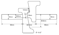
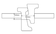
- FIGS. 12A to 12E are cross-sectional views showing the dimensions of each part in the first to fifth embodiments.
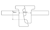
- the size of the gap g is 32.6 mm in Example 1, 33.0 mm in Example 2, 34.0 mm in Example 3, and 35.0 mm in Example 4.
- it is 36.0 mm.
- the nominal compressive stress ⁇ C due to the compressive force F that is, the compressive force F divided by the area of the end face 1E of the lower flange 1B of the beam 1
- the compressive strain ⁇ C of the gap g that is, the compressive force F
- the relationship with the reduction ratio of the gap g was calculated by FEA.
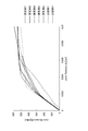
- FIG. 13 is a graph showing the relationship between the nominal compressive stress and the compressive strain calculated in the examples.
- FIG. 13 shows the relationship between the nominal compressive stress ⁇ C and the compressive strain ⁇ C calculated for each of Examples 1 to 5 above, and the nominal values calculated in Comparative Example 1 and Comparative Example 2 in the same manner. The relationship between the compressive stress ⁇ C and the compressive strain ⁇ C is shown.
- Comparative Example 1 is an example in which the member to be joined and the support member are continuous to form a complete rigid connection
- Comparative Example 2 is shown in FIG. 17 in the gap g between the member to be joined and the support member. This is an example in which a wedge-shaped joining member 91 is inserted.
- the rigidity with respect to the moment was calculated by FEA.
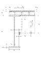
- the dimensions shown in FIG. 14 are applied to the joining structure including the joining member 10 described with reference to FIG. 1 and the same as the example shown in FIGS. 12A to 12E above.
- the rotation angle ⁇ j of the beam 1 with respect to the moment M j when the size of the gap g was changed was calculated by FEA.
- the compression rigidity indicated by the contact between the lower flange 1B of the beam 1 and the flange connecting plate 32, and the tensile rigidity indicated by the joint between the upper flange 1A of the beam 1 and the RC floor slab 5 are used.
- H p 900 mm
- H s 500 mm
- B pf 300 mm
- t pf 25 mm
- t pw 14 mm
- t sf 12 mm
- w rib 118 mm
- D S 150 mm
- d r1 25 mm
- d r2 45 mm
- h j 200 mm
- d g1 40 mm
- d g2 40 mm.
- FIG. 15 is a graph showing the relationship between the moment calculated in the example and the rotation angle. 15 shows the relationship between the moment M j calculated for each angle of rotation phi j of Examples 1 to 5, and, rotation moment M j calculated in the same manner in Comparative Example 1 and Comparative Example 2 The relationship with the angle ⁇ j is shown. From the results shown in FIG. 15, it can be seen that in each of Examples 1 to 5, the rotation angle ⁇ j behaves in a manner close to that of Comparative Example 1 in which the rotation angle ⁇ j is a rigid connection when the moment M j is small.
- FIG. 16 is a graph showing the examination results regarding the tilt angle ⁇ in the embodiment of the present invention.
- the compressive force F is Fsin ⁇ in the direction along the contact surface between the first member 11 and 11A and the second member 12 and 12A, and is perpendicular to the contact surface.
- a component force of Fcos ⁇ is generated in the direction.
- the component force Fsin ⁇ in the direction along the contact surface depends on the component force Fcos ⁇ in the direction perpendicular to the contact surface. It is sufficient that the maximum static frictional force that occurs, ⁇ F cos ⁇ , is not exceeded.
- ⁇ is a coefficient of static friction between the first members 11 and 11A and the second members 12 and 12A, and is determined by the material and surface condition of the first members 11 and 11A and the second members 12 and 12A. .. If the above condition is expressed by a mathematical expression, Fsin ⁇ ⁇ ⁇ F cos ⁇ , that is, tan ⁇ ⁇ ⁇ .
- the slip coefficient in this case, equal to the static friction coefficient ⁇
- the slip coefficient is 0.2.
- To 0.35 High-Strength Bolted Joint Design and Construction Guidebook, 2nd Edition, May 2016.
- “Maximum Bevel for Mill scale surface” shown in FIG. 16 indicates the maximum value (about 14 °) of the inclination angle ⁇ when the slip coefficient is 0.25.
- the slip coefficient is 0.4 to 0.7.
- “Maximum Bevel for Blast-cleaned surface” shown in FIG. 16 indicates the maximum value (about 24.2 °) of the inclination angle ⁇ when the slip coefficient is 0.45.
Landscapes
- Engineering & Computer Science (AREA)
- Architecture (AREA)
- Physics & Mathematics (AREA)
- Electromagnetism (AREA)
- Civil Engineering (AREA)
- Structural Engineering (AREA)
- Joining Of Building Structures In Genera (AREA)
Abstract
第1部材と第2部材とを含み、被接合部材と支持部材との間で圧縮力を伝達する接合部材が提供される。第1部材は、被接合部材の材軸方向の端面に当接される第1後端面と、第1後端面とは反対側に、第1後端面に対して傾斜をもって形成される接触面とを含み、第2部材は、被接合部材の端面に対向する支持部材の面に当接される第2後端面と、第2後端面とは反対側に、第2後端面に対して傾斜をもって形成され、かつ被接合部材の材軸方向を含む鉛直断面における寸法が第1部材の接触面とは異なる接触面とを含み、第1部材の接触面と第2部材の接触面とが互いに接触する。
Description
本発明は、接合部材および接合構造に関する。
例えば、RC柱、SRC柱、RC梁もしくはRC壁を支持部材とし鉄骨大梁を被接合部材とする場合、またはRC大梁もしくは鉄骨大梁を支持部材とし鉄骨小梁を被接合部材とする場合に、支持部材と被接合部材との間に形成される梁端接合部は、一般的に剛接合またはピン接合として設計される。鉄骨大梁と鉄骨小梁との例でいうと、剛接合の場合には鉄骨小梁のフランジを鉄骨大梁に溶接またはボルト接合し、さらに鉄骨小梁のウェブを鉄骨大梁にボルト接合する。ピン接合の場合、鉄骨大梁に取り付けたシアプレートに鉄骨小梁のウェブをボルト接合し、鉄骨小梁のフランジは鉄骨大梁に接合しない。
これに対して、非特許文献1には、水平力を負担しないグラビティフレームや、水平力が小さく逆対称曲げにならない場合のモーメントフレームなど、接合部のモーメントが逆転しない荷重条件下で適用可能なコンタクトプレートを用いた接合が記載されている。コンタクトプレートは、被接合部材である鉄骨梁の下フランジの小端面と支持部材との間の隙間に介挿され、鉄骨梁の圧縮側フランジの力を対向する支持部材に伝達する。
ところが、一般に、鉄骨梁の下フランジの小端面と支持部材との間の隙間は、建方精度のばらつきなどによってその寸法が変動する。コンタクトプレートの厚みが隙間の寸法に対応していなければ力は伝達されないため、コンタクトプレートの厚みを可変にする必要がある。具体的には、特許文献1および特許文献2では、コンタクトプレートに相当する部材をくさび状にすることによって隙間の寸法変動に対応する技術が記載されている。
EUROPEAN COMMITTEE FOR STANDARDIZATION、「Eurocode 4: Design of Composite Steel and Concrete Structures Part 1-8: Design of joints」、2005年5月
しかしながら、例えば図17に示すように接合部材91をくさび状にした場合、被接合部材または支持部材の少なくともいずれかとの間の接触領域が線状あるいはフランジ板厚に対して狭幅になる。この場合、フランジの断面積に対して接触領域が極端に小さい局所支圧状態になるため、圧縮力に対応する支圧部の応力が大きくなり塑性変形が生じる。従って、この場合、圧縮力Fに対する剛性および耐力を安定させることが困難である。
また、例えば図18Aおよび図18Bに示すように接合部材92A,92Bを対向する傾斜面を有する2ピースの部材にした場合、図17の例よりも接触領域は広くなるが、図示されているように隙間の寸法変動に対して接触領域の大きさ(断面における寸法d1,d2として示す)が変動してしまう。
そこで、本発明は、接合部材を寸法が変動する部材間の隙間に介挿することが可能であり、かつ部材間の寸法にかかわらず一定の大きさの接触領域を確保することが可能な、新規かつ改良された接合部材および接合構造を提供することを目的とする。
本発明のある観点によれば、第1部材と第2部材とを含み、被接合部材と支持部材との間で圧縮力を伝達する接合部材が提供される。第1部材は、被接合部材の材軸方向の端面に当接される第1後端面と、第1後端面とは反対側に、第1後端面に対して傾斜をもって形成される接触面とを含み、第2部材は、被接合部材の端面に対向する支持部材の面に当接される第2後端面と、第2後端面とは反対側に、第2後端面に対して傾斜をもって形成され、かつ被接合部材の材軸方向を含む鉛直断面における寸法が第1部材の接触面とは異なる接触面とを含み、第1部材の接触面と第2部材の接触面とが互いに接触する。
上記の接合部材において、第1部材は、第1後端面から被接合部材側に突出する突出部をさらに含んでもよい。また、上記の接合部材において、第2部材は、第2後端面から支持部材側に突出する突出部をさらに含んでもよい。
上記の接合部材において、第1後端面は、被接合部材の端面に面接触してもよい。また、第2後端面は、支持部材の面に面接触してもよい。
上記の接合部材において、第1部材の接触面内において傾斜に直交する方向の寸法と、第2部材の接触面内において傾斜に直交する方向の寸法とが互いに異なっていてもよい。また、被接合部材の材軸方向で見た場合に、第1部材の接触面の傾斜の方向は第2部材の接触面の傾斜の方向に対して角度を有していてもよい。
上記の接合部材において、第1部材の接触面は、第1接触面と、第1接触面に対して平行であり、かつ第1接触面に対して第1後端面側に後退して形成される第2接触面とを含み、第2部材の接触面は、鉛直断面における寸法が第1接触面よりも大きい第3接触面と、第3接触面に対して平行であり、第3接触面に対して第2後端面とは反対側に前進して形成され、かつ鉛直断面における寸法が第2接触面よりも小さい第4接触面とを含み、第1接触面と第3接触面とが互いに接触し、第2接触面と第4接触面とが互いに接触してもよい。
上記の接合部材において、第1部材は、鉛直断面において第1接触面の反対側で第2接触面に隣接して位置し、かつ第2接触面から突出する突出部をさらに含んでもよい。
上記の接合部材において、第1部材は、鉛直断面において第1接触面の反対側で第2接触面に隣接して位置し、第1接触面および第2接触面に対して平行であり、かつ第2接触面に対して第1後端面とは反対側に前進して形成される第5接触面をさらに含み、第2部材は、鉛直断面において第3接触面の反対側で第4接触面に隣接して位置し、第3接触面および第4接触面に対して平行であり、第4接触面に対して第2後端面側に後退して形成され、かつ鉛直断面における寸法が第5接触面よりも大きい第6接触面をさらに含み、第5接触面と第6接触面とが互いに接触してもよい。
上記の接合部材において、傾斜の角度θと、第1部材と第2部材との間の静止摩擦係数μとが、tanθ≦μの関係を満たしてもよい。
上記の接合部材において、第1部材は、第1部材の接触面および第1後端面の両方に直交する断面の形状が一様であってもよい。また、第2部材は、第2部材の接触面および第2後端面の両方に直交する断面の形状が一様であってもよい。
本発明の別の観点によれば、被接合部材と、支持部材と、被接合部材の端面と支持部材の面との間の隙間に介挿される上記の接合部材とを備える接合構造が提供される。材軸方向を含む水平断面において、被接合部材の端面と支持部材の面とは非平行であってもよい。
上記の接合構造は、コンクリート、およびコンクリートに埋設される鉄筋を含み、被接合部材および支持部材の上方に配置されるRC床スラブをさらに備え、被接合部材は、支持部材の両側にそれぞれ配置される第1のH形断面梁および第2のH形断面梁を含み、被接合部材の端面は、第1のH形断面梁の下フランジの材軸方向の端面と、第2のH形断面梁の下フランジの材軸方向の端面とを含み、接合部材は、第1のH形断面梁および第2のH形断面梁のそれぞれの下フランジの端面と支持部材の面との間の隙間にそれぞれ介挿される1対の接合部材を含み、RC床スラブは、第1のH形断面梁、第2のH形断面梁および支持部材の上方に配置され、第1のH形断面梁の上フランジ、および第2のH形断面梁の上フランジは、シアコネクタを用いてRC床スラブに接合されてもよい。
上記の接合構造において、被接合部材は第1のH形断面梁であり、被接合部材の端面は第1のH形断面梁の下フランジの材軸方向の端面であり、支持部材は第2のH形断面梁であり、支持部材の面は第2のH形断面梁の下フランジの幅方向の端面であり、第1のH形断面梁と第2のH形断面梁との断面高さが等しくてもよい。
上記の構成によれば、第1部材と第2部材とが、接触面の接触を維持したまま、鉛直方向に対して角度θだけ傾いた方向で、互いに対して摺動することができる。第1部材と第2部材との間の摺動距離をLとすると、第1部材の第1後端面と第2部材の第2後端面との間の距離はLsinθだけ変化する。従って、接合部材は、寸法が変動する部材間の隙間に介挿することができる。また、上記のような各接触面の寸法の大小関係によって、第1部材と第2部材とが互いに対して摺動しても、第1接触面と第3接触面との間の接触面積は第1接触面の寸法に依存して一定であり、第2接触面と第4接触面との間の接触面積も第4接触面の寸法に依存して一定である。従って、接合部材では、部材間の隙間の寸法にかかわらず、一定の大きさの接触領域を確保することができる。
以下に添付図面を参照しながら、本発明の好適な実施形態について詳細に説明する。なお、本明細書および図面において、実質的に同一の機能構成を有する構成要素については、同一の符号を付することにより重複説明を省略する。
(第1の実施形態)
図1は、本発明の第1の実施形態に係る接合構造を示す図である。図示された例において、接合構造は、被接合部材である小梁1と、大梁2に接合される支持部材であるシアプレート31およびフランジ連結板32と、RC床スラブ(または合成デッキスラブ)5と、接合部材10とを含む。より詳細には、小梁1は、上フランジ1Aと、下フランジ1Bと、ウェブ1Cとを含むH形断面梁である。大梁2は、小梁1の材軸方向に直交する方向に延び、上フランジ2Aと、下フランジ2Bと、ウェブ2Cとを含む支持側H形断面梁である。シアプレート31は、大梁2に直交する板状部材であり、ウェブ2Cの少なくとも片側に配置されて上フランジ2A、下フランジ2B、およびウェブ2Cに溶接される。フランジ連結板32は、大梁2の上フランジ2Aおよび下フランジ2Bに平行な板状部材であり、ウェブ2Cおよびシアプレート31に溶接される。フランジ連結板32の端面32Eは、小梁1の材軸方向における下フランジ1Bの端面1Eに対向する。RC床スラブ5は、コンクリート51と、コンクリート51に埋設される鉄筋52と、デッキプレート53と、シアコネクタ54とを含み、小梁1の上フランジ1Aおよび大梁2の上フランジ2Aはシアコネクタ54を介してRC床スラブ5に接合される。接合部材10は、小梁1の下フランジ1Bの材軸方向の端面1Eと、端面1Eに対向するフランジ連結板32の端面32Eとの間の隙間gに介挿され、小梁1とフランジ連結板32との間で圧縮力を伝達する。
図1は、本発明の第1の実施形態に係る接合構造を示す図である。図示された例において、接合構造は、被接合部材である小梁1と、大梁2に接合される支持部材であるシアプレート31およびフランジ連結板32と、RC床スラブ(または合成デッキスラブ)5と、接合部材10とを含む。より詳細には、小梁1は、上フランジ1Aと、下フランジ1Bと、ウェブ1Cとを含むH形断面梁である。大梁2は、小梁1の材軸方向に直交する方向に延び、上フランジ2Aと、下フランジ2Bと、ウェブ2Cとを含む支持側H形断面梁である。シアプレート31は、大梁2に直交する板状部材であり、ウェブ2Cの少なくとも片側に配置されて上フランジ2A、下フランジ2B、およびウェブ2Cに溶接される。フランジ連結板32は、大梁2の上フランジ2Aおよび下フランジ2Bに平行な板状部材であり、ウェブ2Cおよびシアプレート31に溶接される。フランジ連結板32の端面32Eは、小梁1の材軸方向における下フランジ1Bの端面1Eに対向する。RC床スラブ5は、コンクリート51と、コンクリート51に埋設される鉄筋52と、デッキプレート53と、シアコネクタ54とを含み、小梁1の上フランジ1Aおよび大梁2の上フランジ2Aはシアコネクタ54を介してRC床スラブ5に接合される。接合部材10は、小梁1の下フランジ1Bの材軸方向の端面1Eと、端面1Eに対向するフランジ連結板32の端面32Eとの間の隙間gに介挿され、小梁1とフランジ連結板32との間で圧縮力を伝達する。
図2は図1に示された接合部材10を拡大して示す斜視図であり、図3は図2のIII-III線断面図である。図示されるように、接合部材10は、第1部材11と第2部材12とを含み、上述したように小梁1の下フランジ1Bとフランジ連結板32との間で圧縮力Fを伝達する。図示された例において、圧縮力Fの伝達方向(図中のx方向)は、小梁1の材軸方向に一致する。第1部材11は、第1後端面111と、第1接触面112と、第2接触面113と、第1突出部114と、第2突出部115とを含む。第1接触面112、第2接触面113および第2突出部115は第1後端面111とは反対側に形成され、第1突出部114は第1後端面111と同じ側に形成される。第2部材12は、第2後端面121と、第3接触面122と、第4接触面123と、第3突出部124とを含む。第3接触面122および第4接触面123は第2後端面121とは反対側に形成され、第3突出部124は第2後端面121と同じ側に形成される。本実施形態において、第1部材11は、接触面(第1接触面112および第2接触面113)および第1後端面111の両方に直交する断面(図中のx-z断面)の形状が一様である。また、第2部材12も、接触面(第3接触面122および第4接触面)および第2後端面121の両方に直交する断面(図中のx-z断面)の形状が一様である。
上記で図1に示したような接合構造が組み立てられた状態において、接合部材10に含まれる第1部材11の第1後端面111は、小梁1の下フランジ1Bの端面1Eに当接される。端面1Eは、小梁1の材軸方向における端面である。図示された例では端面1Eが小梁1の材軸方向に対して垂直であるため、第1後端面111も小梁1の材軸方向に対して垂直に形成される。これによって、第1後端面111は、端面1Eに面接触する。一方、第1部材11の第1接触面112は、図3に示されるように第1後端面111に対して角度θ(0<θ<90°)の傾斜をもって形成される。なお、図3に示された平面P(y-z平面)は、第1後端面111に対して平行である。第2接触面113は、第1接触面112に対して平行であり、かつ第1接触面112に対して第1後端面111側に後退して形成される。つまり、図示されているように第1部材11と第2部材12とが互いに対向させられた状態では、第1接触面112よりも第2接触面113の方が第2部材12から離れている。
また、接合構造が組み立てられた状態において、第2部材12の第2後端面121は、フランジ連結板32の端面32Eに当接される。図示された例では、端面32Eも小梁1の材軸方向に対して垂直であるため、第2後端面121も小梁1の材軸方向に対して垂直に形成される。これによって、第2後端面121は、端面32Eに面接触する。一方、第2部材12の第3接触面122は、第1部材11の第1接触面112と同じく、図3に示されるように第2後端面121に対して角度θだけ傾斜して形成される。なお、図3に示された平面Pは、第2後端面121に対しても平行である。第4接触面123は、第3接触面122に対して平行であり、かつ第3接触面122に対して第2後端面121と反対側に前進して形成される。つまり、図示されているように第1部材11と第2部材12とが互いに対向させられた状態では、第3接触面122よりも第4接触面123の方が第1部材11に近づいている。
なお、図示された例において、第1部材11および第2部材12は、小梁1のウェブ1Cと下フランジ1Bの幅方向端部との間に収容可能な幅(図中のy方向の長さ)を有している。この例に限定されず、第1部材11および第2部材12の幅は、隙間gの大きさ、被接合部材(図示された例では小梁1)、および支持部材(図示された例では大梁2)の断面形状などに応じて、それぞれの場合において隙間g内に安定的に介挿された状態を維持できるように適宜決定される。
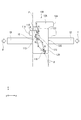
上記のような接合部材10では、第1部材11の第1接触面112と第2部材12の第3接触面122とが互いに接触し、第1部材11の第2接触面113と第2部材12の第4接触面123とが互いに接触する。ここで、図3に示されるように、小梁1の材軸方向を含む鉛直断面において、第3接触面122の寸法d3は第1接触面112の寸法d1よりも大きく、第4接触面123の寸法d4は第2接触面113の寸法d2よりも小さい。これによって、第1部材11と第2部材12とは、上記のような2組の接触面の接触を維持したまま、鉛直方向に対して角度θだけ傾いた方向で、互いに対して摺動することができる。図4に示すように、第1部材11と第2部材12との間に摺動距離Lが発生すると、第1部材11の第1後端面111と第2部材12の第2後端面121との間の距離はLsinθだけ変化する(図示された例では、第2後端面121が第1後端面111から遠ざかる)。従って、接合部材10は、寸法が変動する部材間の隙間、具体的には小梁1の下フランジ1Bの端面1Eとフランジ連結板32の端面32Eとの間の隙間g(図1参照)に介挿することができる。
ここで、上記のような各接触面の寸法の大小関係(具体的には、d3>d1、d4<d2)によって、第1部材11と第2部材12とが互いに対して摺動しても、第1接触面112と第3接触面122との間の接触面積は第1接触面112の寸法d1に依存して一定であり、第2接触面113と第4接触面123との間の接触面積も第4接触面123の寸法d4に依存して一定である。従って、接合部材10では、部材間の隙間の寸法、具体的には小梁1の下フランジ1Bの端面1Eとフランジ連結板32の端面32Eとの間の隙間gの寸法にかかわらず、一定の大きさの接触領域を確保することができる。これによって、小梁1とフランジ連結板32との間で、安定して圧縮力Fを伝達することができる。
加えて、本実施形態では、第1部材11に第1後端面111から小梁1側に突出する第1突出部114が形成され、第2部材12に第2後端面121からフランジ連結板32側に突出する第3突出部124が形成される。第1突出部114および第3突出部124は、例えば図示されているように接合構造が組み立てられた状態において第1後端面111および第2後端面121のそれぞれの上端にあたる位置から突出する。これによって、小梁1の材軸方向(図中のx方向)について、第1部材11および第2部材12のそれぞれの寸法が大きくなるため、第1部材11または第2部材12が隙間gから脱落することを防止でき、施工が容易になる。なお、こうした機能が必要ではない場合は、第1突出部114および第3突出部124は設けられなくてもよい。また、第1突出部114および第3突出部124のいずれか一方だけが設けられてもよい。
また、本実施形態では、第1部材11に、小梁1の材軸方向を含む鉛直断面(図中のx-z断面)において第1接触面112の反対側で第2接触面113に隣接して位置し、かつ第2接触面113から突出する第2突出部115が形成される。第2突出部115によって、第2部材12の第1部材11に対する摺動が、第4接触面123が第2接触面113の下端に達したところで規制される。従って、例えば隙間gが大きすぎた場合にも、第2部材12がフランジ連結板32の端面32Eと第1部材11との間から脱落することが防止される。なお、図示された例では第2部材12の第3突出部124によっても同様の機能が得られる。こうした機能が必要ではない場合は、第2突出部115は設けられなくてもよい。
以上で説明したように、本発明の第1の実施形態では、寸法が変動する部材間の隙間、具体的には小梁1の下フランジ1Bの端面1Eとフランジ連結板32の端面32Eとの間の隙間gに接合部材10を介挿することができ、また接合部材10によって隙間gの寸法にかかわらず一定の大きさの接触領域を確保することができる。加えて、上述したように第1部材11および第2部材12はいずれも断面の形状が一様であるため、例えば押出成形によって容易に製造することができる。この例に限定されず、第1部材11および第2部材12は、鋳造や鍛造、切削など他の方法で製造されてもよい。また、第1部材11および第2部材12は必ずしも断面方向、および長手方向について一体に形成されなくてもよく、第1部材11および第2部材12のいずれか、または両方が複数の部分をねじ止めや溶接などの各種の手法で接合することによって形成されてもよい。
図5は、本発明の第1の実施形態に係る接合構造の別の例を示す図である。図示された例において、接合構造は、被接合部材である小梁1(第1のH形断面梁)と、支持部材である大梁4(第2のH形断面梁)と、接合部材10とを含む。図1に示された例との違いとして、図5に示された例では、小梁1の断面高さ(梁せい)HSと大梁4の断面高さ(梁せい)HPとが等しい。これによって、接合部材10を、小梁1の下フランジ1Bの材軸方向の端面1Eと、端面1Eに対向する大梁4の下フランジ4Bの幅方向の側端面4Eとの間の隙間gに介挿することができる。なお、図示されているように、大梁4の下フランジ4Bの厚みtpfが、小梁1の下フランジ1Bの厚みtsfよりも大きくてもよい。
図6は、本発明の第1の実施形態に係る接合構造のさらに別の例を示す図である。図示された例では、被接合部材である2つの小梁1が、大梁2を幅方向の両側から挟んで対向するように配置され、支持部材であるシアプレート31およびフランジ連結板32、ならびに接合部材10も、大梁2の両側にそれぞれ配置される。つまり、図示された例では、接合構造に、2つの小梁1(第1のH形断面梁および第2のH形断面梁)のそれぞれの下フランジ1Bの端面1Eと支持部材の面との間の隙間gにそれぞれ介挿される1対の接合部材10が含まれる。図示された例において、RC床スラブ5は、2つの小梁1、大梁2、およびそれらの間のシアプレート31およびフランジ連結板32の上方に配置され、1つの小梁1のそれぞれの上フランジ1A、および大梁2の上フランジ2Aは、シアコネクタ54を用いてRC床スラブ5に接合される、
上記の例において、接合部材10は、大梁2の両側で小梁1の下フランジ1Bの端面1Eとフランジ連結板32の端面32Eとの間に形成される2ヶ所の隙間gにそれぞれ介挿され、フランジ連結板32および大梁2を介して、2つの小梁1の下フランジ1B同士の間で圧縮力を伝達する。ここで、2つの小梁1のそれぞれの下フランジ1Bの厚みtsf1,tsf2は互いに異なってもよいが、断面高さ(梁せい)は2つの小梁1で一致することが好ましい。また、図5の例と同様に大梁を支持部材とし、2つの小梁および大梁の断面高さを一致させて、それぞれの小梁の下フランジの端面と、大梁の下フランジの幅方向両側の側端面との間の隙間gに接合部材を介挿してもよい。この場合、大梁の下フランジの厚みは、それぞれの小梁の下フランジの厚みよりも大きくてもよい。
図7も、本発明の第1の実施形態に係る接合構造のさらに別の例を示す図である。図示された例は、小梁1、シアプレート31および接合部材10が大梁2の両側にそれぞれ配置され、両方の小梁1の上フランジ1Aおよび大梁2の上フランジ2Aがそれぞれシアコネクタ54を介してRC床スラブ5に接合される点では図6の例と同様である。その一方で、図7の例では、小梁1の下フランジ1Bおよびウェブ1Cが大梁2のウェブ2Cに対向する位置まで延び、小梁1の上フランジ1Aおよびウェブ1Cの一部は大梁2の上フランジ2Aと干渉する部分において切り欠かれている。これによって、小梁1の下フランジ1Bの端面1Eは大梁2のウェブ2Cの側面2Sに対向し、接合部材10は下フランジ1Bの端面1Eとウェブ2Cの側面2Sとの間に介挿される。この例では、フランジ連結板32は設けられない。さらに、小梁1のウェブ1Cの端部を大梁2のウェブ2Cに溶接して、シアプレート31を設けないことも可能である。
上記の例において、接合部材10は、大梁2の両側で小梁1の下フランジ1Bの端面1Eと大梁2のウェブ2Cの側面2Sとの間に形成される2ヶ所の隙間gにそれぞれ介挿され、小梁1の下フランジ1Bと大梁2との間で圧縮力を伝達する。図示された例におけるウェブ2Cの側面2Sのように、支持部材の面が接合部材10の鉛直寸法よりも大きい鉛直面であるような場合、支持部材の面に当接される第2後端面から支持部材側に突出する突出部(具体的には、図2に示される第2部材12の第2後端面121から突出する第3突出部124)は設けられない。これによって、大梁2の代わりに、例えばRC梁やRC柱、またはRC壁に小梁1を接合する場合にも、小梁1の下フランジ1Bの端面1Eと対向する支持部材の側面との間に形成される隙間gに接合部材10を介挿することができる。図6の例と同様に、2つの小梁1のそれぞれの下フランジ1Bの厚みtsf1,tsf2は互いに異なってもよいが、断面高さ(梁せい)は2つの小梁1で一致することが好ましい。
(第2の実施形態)
図8は本発明の第2の実施形態に係る接合部材の斜視図であり、図9は図8のIX-IX線断面図である。図示されるように、接合部材10Aは、第1部材11Aと第2部材12Aとを含み、被接合部材である小梁1の下フランジ1Bと、支持部材であるフランジ連結板32との間で圧縮力Fを伝達する。なお、以下で説明する接合部材10Aの第1部材11Aおよび第2部材12Aの構成を除いて、本実施形態は上記の第1の実施形態と同様に構成されるため、重複した説明は省略する。
図8は本発明の第2の実施形態に係る接合部材の斜視図であり、図9は図8のIX-IX線断面図である。図示されるように、接合部材10Aは、第1部材11Aと第2部材12Aとを含み、被接合部材である小梁1の下フランジ1Bと、支持部材であるフランジ連結板32との間で圧縮力Fを伝達する。なお、以下で説明する接合部材10Aの第1部材11Aおよび第2部材12Aの構成を除いて、本実施形態は上記の第1の実施形態と同様に構成されるため、重複した説明は省略する。
本実施形態において、第1部材11Aは、第1後端面111と、第1接触面112と、第2接触面113と、第1突出部114と、第5接触面116とを含む。本実施形態において第1部材11Aに追加される第5接触面116は、他の接触面と同様に第1後端面111とは反対側に形成される。また、第5接触面116は、圧縮力Fの伝達方向、すなわち小梁1の材軸方向を含む鉛直断面(図中のx-z断面)において第1接触面112の反対側で第2接触面113に隣接して位置し、第1接触面112および第2接触面113に対して平行であり、かつ第2接触面113に対して第1後端面111とは反対側に前進して形成される。つまり、図示されているように第1部材11Aと第2部材12Aとが互いに対向された状態では、第2接触面113よりも第5接触面116の方が第2部材12Aに近づいている。
一方、本実施形態において、第2部材12Aは、第2後端面121と、第3接触面122と、第4接触面123と、第3突出部124と、第6接触面126とを含む。本実施形態において第2部材12Aに追加される第6接触面126は、他の接触面と同様に第2後端面121とは反対側に形成される。また、第6接触面126は、圧縮力Fの伝達方向、すなわち小梁1の材軸方向を含む鉛直断面において第3接触面122の反対側で第4接触面123に隣接して位置し、第3接触面122および第4接触面123に対して平行であり、かつ第4接触面123に対して第2後端面121側に後退して形成される。つまり、図示されているように第1部材11Aと第2部材12Aとが互いに対向された状態では、第4接触面123よりも第6接触面126の方が第1部材11Aから離れている。
上記のような接合部材10Aでは、第1部材11Aの第1接触面112と第2部材12Aの第3接触面122とが互いに接触し、第1部材11Aの第2接触面113と第2部材12Aの第4接触面123とが互いに接触するのに加えて、第1部材11Aの第5接触面116と第2部材12Aの第6接触面126とが互いに接触する。ここで、図9に示されるように、小梁1の材軸方向を含む鉛直断面において、第5接触面116の寸法d5は第6接触面126の寸法d6よりも小さい。これによって、第1部材11Aと第2部材12Aとは、上記のような3組の接触面の接触を維持したまま、鉛直方向に対して角度θだけ傾いた方向で、互いに対して摺動することができる。
従って、本実施形態でも、上記の第1の実施形態と同様に、寸法が変動する部材間の隙間、具体的には小梁1の下フランジ1Bの端面1Eとフランジ連結板32の端面32Eとの間の隙間g(図1参照)に接合部材10Aを介挿することができ、また接合部材10Aによって隙間gの寸法にかかわらず一定の大きさの接触領域を確保することができる。第1部材11Aおよび第2部材12Aを例えば押出成形などによって容易に製造することができる点も第1の実施形態と同様である。
(第3の実施形態)
図10は、本発明の第3の実施形態に係る接合構造の斜視図であり、図11は図10のXI-XI線断面図である。図示されるように、接合部材10Bは、第1部材11Bと第2部材12Bとを含み、被接合部材である小梁1の下フランジ1Bと、支持部材であるフランジ連結板32との間で圧縮力を伝達する。なお、以下で説明する接合部材10Bの構成、および小梁1とフランジ連結板32との位置関係を除いて、本実施形態は上記の第1の実施形態と同様に構成されるため、重複した説明は省略する。
図10は、本発明の第3の実施形態に係る接合構造の斜視図であり、図11は図10のXI-XI線断面図である。図示されるように、接合部材10Bは、第1部材11Bと第2部材12Bとを含み、被接合部材である小梁1の下フランジ1Bと、支持部材であるフランジ連結板32との間で圧縮力を伝達する。なお、以下で説明する接合部材10Bの構成、および小梁1とフランジ連結板32との位置関係を除いて、本実施形態は上記の第1の実施形態と同様に構成されるため、重複した説明は省略する。
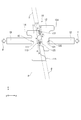
本実施形態において、第1部材11Bは、第1後端面111と、第1接触面112と、第2接触面113と、第1突出部114とを含む。第1部材11Bの各部は、第2突出部115を除いて、図1に示した第1部材11と同様に構成される。一方、第2部材12Bは、第2後端面121と、第3接触面122と、第4接触面123と、第3突出部124とを含む。第2部材12Bの各部は、図1に示した第2部材12と同様に構成される。図10に示されるように、本実施形態では、第1部材11Bの幅W1、すなわち接触面(第1接触面112および第2接触面113)内において傾斜に直交する方向の寸法と、第2部材12Bの幅W2、すなわち接触面(第3接触面122および第4接触面123)内において傾斜に直交する方向の寸法とが互いに異なる。具体的には、幅W1は幅W2よりも大きい。
また、図11に示されるように、本実施形態の例では、小梁1の直角度公差のために、小梁1が大梁2に対して直角に配置されておらず、小梁1の材軸方向を含む水平断面(図中のx-y平面)において、下フランジ1Bの端面1Eとフランジ連結板32の端面32Eとは非平行である。この場合、端面1Eと端面32Eとの間の隙間は、下フランジ1Bの幅方向両側で異なる(隙間g1および隙間g2として図示)。
そこで、本実施形態では、図10に示されるように、第1部材11Bの接触面(第1接触面112および第2接触面113)の傾斜の方向と第2部材12Bの接触面(第3接触面122および第4接触面123)の傾斜の方向とが非平行になる(角度ψを有する)ように、接合部材10Bを端面1Eと端面32Eとの間に介挿している。これによって、接触面同士の接触を維持しつつ、水平断面内で第1部材11Bの第1後端面111と第2部材12Bの第2後端面121を非平行にすることができ、第1後端面111および第2後端面121をそれぞれ端面1Eおよび端面32Eに面接触させることができる。つまり、本実施形態では、接合部材10Bを用いて小梁1の直角度公差を吸収することができる。
上述のように、本実施形態では、第1部材11Bの幅W1が第2部材12Bの幅W2よりも大きいため、それぞれの接触面の傾斜の方向を非平行にしても部材間の接触面積が一定に維持される。なお、図示された例では第1部材11Bの幅W1が第2部材12Bの幅W2よりも大きいが、逆に第1部材の幅が第2部材の幅よりも小さい場合にも同様に接触面積を一定に維持することができる。また、第1部材の幅と第2部材の幅とが同じである場合、それぞれの接触面の傾斜の方向を非平行にすると部材間の接触面積は減少するが、接触面の傾斜の方向を非平行にしたことによる接触面積の減少は全体に比べて小さいため、接触領域の大きさはほぼ一定である。
続いて、本発明の実施例について説明する。まず、上記で図2および図3を参照して接合部材10について、隙間gの寸法に応じて第1部材11と第2部材12とが互いに対して摺動して位置関係が変化した複数の場合において、FEA(Finite Element Analysis)を用いて公称圧縮応力と圧縮ひずみとの関係をシミュレートした。
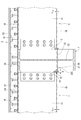
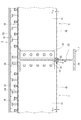
図12A~図12Eは、実施例1~実施例5における各部の寸法を示す断面図である。図12A~図12Eに示されるように、隙間gの寸法は、実施例1で32.6mm、実施例2で33.0mm、実施例3で34.0mm、実施例4で35.0mm、実施例5で36.0mmである。この条件下で、圧縮力Fによる公称圧縮応力σC、すなわち圧縮力Fを小梁1の下フランジ1Bの端面1Eの面積で割ったものと、隙間gの圧縮ひずみεC、すなわち圧縮力Fによる隙間gの縮小率との関係をFEAによって算出した。
図13は、実施例において算出された公称圧縮応力と圧縮ひずみとの関係を示すグラフである。図13には、上記の実施例1~実施例5のそれぞれについて算出された公称圧縮応力σCと圧縮ひずみεCとの関係、および、比較例1および比較例2において同様に算出された公称圧縮応力σCと圧縮ひずみεCとの関係が示されている。ここで、比較例1は被接合部材と支持部材とを連続させて完全な剛結合とした例であり、比較例2は被接合部材と支持部材との間の隙間gに図17に示したようなくさび状の接合部材91を介挿した例である。
上記の図13に示された結果から、実施例1~実施例5ではいずれも、公称圧縮応力σCが小さい段階では圧縮ひずみεCが剛結合である比較例1に近い挙動を示すことがわかる。つまり、本発明の実施例では、隙間gの寸法に応じて第1部材11と第2部材12とが互いに対して摺動して位置関係が変化しても、接合部材10によって示される剛性がほとんど変化しない。一方、隙間gにくさび状の接合部材91を介挿した比較例2では、公称圧縮応力σCが小さくても大きな圧縮ひずみεCが発生する。これは、接合部材91と被接合部材の端面との間の接触領域がフランジ板厚に対して狭幅であり、圧縮力Fがかかった場合に剛性が示されずに部材が変形するためである。
次に、上記の実施例1~実施例5について、モーメントに対する剛性をFEAによって算出した。具体的には、図1を参照して説明した接合部材10を含む接合構造に、図14に示されるような寸法を適用して、上記で図12A~図12Eに示された例と同様に隙間gの寸法が変化した場合のモーメントMjに対する小梁1の回転角度φjをFEAによって算出した。具体的な計算手法としては、小梁1の下フランジ1Bとフランジ連結板32との接触によって示される圧縮剛性、および小梁1の上フランジ1AとRC床スラブ5との接合によって示される引張剛性をそれぞればねとしてモデル化し、モーメントMjが加わったときにこれらのばねに作用する圧縮力および引張力とばねの剛性に応じて生じる変位から被接合部材(小梁1)の回転角度φjを算出した。なお、図14に示された各部の寸法は、以下の通りである。Hp=900mm、HS=500mm、Bpf=300mm、tpf=25mm、tpw=14mm、tsf=12mm、wrib=118mm、DS=150mm、dr1=25mm、dr2=45mm、dr,eq=33mm、hj=200mm、dg1=40mm、dg2=40mm。
図15は、実施例において算出されたモーメントと回転角度との関係を示すグラフである。図15には、実施例1~実施例5のそれぞれについて算出されたモーメントMjと回転角度φjとの関係、および、比較例1および比較例2において同様に算出されたモーメントMjと回転角度φjとの関係が示されている。図15に示された結果から、実施例1~実施例5ではいずれも、モーメントMjが小さい段階では回転角度φjが剛結合である比較例1に近い挙動を示すことがわかる。つまり、本発明の実施例では、隙間gの寸法に応じて第1部材11と第2部材12とが互いに対して摺動して位置関係が変化しても、接合部材10によって示される剛性がほとんど変化しないことによって、小梁1の下フランジ1B側における圧縮剛性が低下せず、従ってモーメントMjに対する小梁1の回転角度φjが抑制されている。一方、隙間gにくさび状の接合部材91を介挿した比較例2では、同じモーメントMjに対して実施例よりも大きな回転角度φjが発生している。これは、接合部材91と小梁の下フランジの端面との間の接触領域が線状であり、圧縮力Fがかかった場合に剛性が示されずに部材が変形するためである。
(傾斜角度に関する検討)
図16は、本発明の実施形態における傾斜角度θに関する検討結果を示すグラフである。上記の第1および第2の実施形態において、圧縮力Fは、第1部材11,11Aと第2部材12,12Aとの間の接触面に沿った方向にFsinθ、接触面に対して垂直な方向にFcosθの分力を生じる。第1部材11,11Aと第2部材12,12Aとの間で滑動が生じないためには、接触面に沿った方向の分力Fsinθが、接触面に対して垂直な方向の分力Fcosθによって生じる最大静止摩擦力μFcosθを超えなければよい。ここで、μは、第1部材11,11Aと第2部材12,12Aとの間の静止摩擦係数であり、第1部材11,11Aおよび第2部材12,12Aの材質、および表面状態によって定まる。上記の条件を数式で表すと、Fsinθ≦μFcosθ、すなわちtanθ≦μとなる。
図16は、本発明の実施形態における傾斜角度θに関する検討結果を示すグラフである。上記の第1および第2の実施形態において、圧縮力Fは、第1部材11,11Aと第2部材12,12Aとの間の接触面に沿った方向にFsinθ、接触面に対して垂直な方向にFcosθの分力を生じる。第1部材11,11Aと第2部材12,12Aとの間で滑動が生じないためには、接触面に沿った方向の分力Fsinθが、接触面に対して垂直な方向の分力Fcosθによって生じる最大静止摩擦力μFcosθを超えなければよい。ここで、μは、第1部材11,11Aと第2部材12,12Aとの間の静止摩擦係数であり、第1部材11,11Aおよび第2部材12,12Aの材質、および表面状態によって定まる。上記の条件を数式で表すと、Fsinθ≦μFcosθ、すなわちtanθ≦μとなる。
ここで、第1部材11,11Aおよび第2部材12,12Aの表面がいずれもミルスケールのまま(黒皮)の場合、すべり係数(この場合は、静止摩擦係数μに等しい)は0.2~0.35になる(日本建築学会「高力ボルト接合設計施工ガイドブック」第2版、2016年5月)。図16に示された「Maximum Bevel for Mill scale surface」は、すべり係数を0.25としたときの傾斜角度θの最大値(約14°)を示す。また、同文献によれば、第1部材11,11Aおよび第2部材12,12Aの表面がブラスト処理されている場合、すべり係数は0.4~0.7になる。図16に示された「Maximum Bevel for Blast-cleaned surface」は、すべり係数を0.45としたときの傾斜角度θの最大値(約24.2°)を示す。
以上、添付図面を参照しながら本発明の好適な実施形態について詳細に説明したが、本発明はかかる例に限定されない。本発明の属する技術の分野における通常の知識を有する者であれば、請求の範囲に記載された技術的思想の範疇内において、各種の変更例または修正例に想到し得ることは明らかであり、これらについても、当然に本発明の技術的範囲に属するものと了解される。
1…小梁、1E…端面、2,4…大梁、31…シアプレート、32…フランジ連結板、5…RC床スラブ、10,10A,10B…接合部材、11,11A,11B…第1部材、12,12A,12B…第2部材、111…第1後端面、112…第1接触面、113…第2接触面、114…第1突出部、115…第2突出部、121…第2後端面、122…第3接触面、123…第4接触面、124…第3突出部、116…第5接触面、126…第6接触面。
Claims (17)
- 第1部材と第2部材とを含み、被接合部材と支持部材との間で圧縮力を伝達する接合部材であって、
前記第1部材は、
前記被接合部材の材軸方向の端面に当接される第1後端面と、
前記第1後端面とは反対側に、前記第1後端面に対して傾斜をもって形成される接触面と
を含み、
前記第2部材は、
前記被接合部材の端面に対向する前記支持部材の面に当接される第2後端面と、
前記第2後端面とは反対側に、前記第2後端面に対して傾斜をもって形成され、かつ前記被接合部材の材軸方向を含む鉛直断面における寸法が前記第1部材の接触面とは異なる接触面と
を含み、
前記第1部材の接触面と前記第2部材の接触面とが互いに接触する、接合部材。 - 前記第1部材は、前記第1後端面から前記被接合部材側に突出する突出部をさらに含む、請求項1に記載の接合部材。
- 前記第2部材は、前記第2後端面から前記支持部材側に突出する突出部をさらに含む、請求項1または請求項2に記載の接合部材。
- 前記第1後端面は、前記被接合部材の端面に面接触する、請求項1から請求項3のいずれか1項に記載の接合部材。
- 前記第2後端面は、前記支持部材の面に面接触する、請求項1から請求項4のいずれか1項に記載の接合部材。
- 前記第1部材の接触面内において傾斜に直交する方向の寸法と、前記第2部材の接触面内において傾斜に直交する方向の寸法とが互いに異なる、請求項1から請求項5のいずれか1項に記載の接合部材。
- 前記第1部材の接触面の傾斜の方向と前記第2部材の接触面の傾斜の方向とは非平行である、請求項1から請求項6のいずれか1項に記載の接合部材。
- 前記第1部材の接触面は、
第1接触面と、
前記第1接触面に対して平行であり、かつ前記第1接触面に対して前記第1後端面側に後退して形成される第2接触面とを含み、
前記第2部材の接触面は、
前記鉛直断面における寸法が前記第1接触面よりも大きい第3接触面と、
前記第3接触面に対して平行であり、前記第3接触面に対して前記第2後端面とは反対側に前進して形成され、かつ前記鉛直断面における寸法が前記第2接触面よりも小さい第4接触面とを含み、
前記第1接触面と前記第3接触面とが互いに接触し、前記第2接触面と前記第4接触面とが互いに接触する、請求項1から請求項7のいずれか1項に記載の接合部材。 - 前記第1部材は、前記鉛直断面において前記第1接触面の反対側で前記第2接触面に隣接して位置し、かつ前記第2接触面から突出する突出部をさらに含む、請求項8に記載の接合部材。
- 前記第1部材は、前記鉛直断面において前記第1接触面の反対側で前記第2接触面に隣接して位置し、前記第1接触面および前記第2接触面に対して平行であり、かつ前記第2接触面に対して前記第1後端面とは反対側に前進して形成される第5接触面をさらに含み、
前記第2部材は、前記鉛直断面において前記第3接触面の反対側で前記第4接触面に隣接して位置し、前記第3接触面および前記第4接触面に対して平行であり、前記第4接触面に対して前記第2後端面側に後退して形成され、かつ前記鉛直断面における寸法が前記第5接触面よりも大きい第6接触面をさらに含み、
前記第5接触面と前記第6接触面とが互いに接触する、請求項8に記載の接合部材。 - 前記傾斜の角度θと、前記第1部材と前記第2部材との間の静止摩擦係数μとが、tanθ≦μの関係を満たす、請求項1から請求項10のいずれか1項に記載の接合部材。
- 前記第1部材は、前記第1部材の接触面および前記第1後端面の両方に直交する断面の形状が一様である、請求項1から請求項11のいずれか1項に記載の接合部材。
- 前記第2部材は、前記第2部材の接触面および前記第2後端面の両方に直交する断面の形状が一様である、請求項1から請求項12のいずれか1項に記載の接合部材。
- 前記被接合部材と、
前記支持部材と、
前記被接合部材の端面と前記支持部材の面との間の隙間に介挿される、請求項1から請求項13のいずれか1項に記載の接合部材と
を備える接合構造。 - 前記材軸方向を含む水平断面において、前記被接合部材の端面と前記支持部材の面とは非平行である、請求項14に記載の接合構造。
- コンクリート、および前記コンクリートに埋設される鉄筋を含み、前記被接合部材および前記支持部材の上方に配置されるRC床スラブをさらに備え、
前記被接合部材は、前記支持部材の両側にそれぞれ配置される第1のH形断面梁および第2のH形断面梁を含み、
前記被接合部材の端面は、前記第1のH形断面梁の下フランジの材軸方向の端面と、前記第2のH形断面梁の下フランジの材軸方向の端面とを含み、
前記接合部材は、前記第1のH形断面梁および前記第2のH形断面梁のそれぞれの下フランジの端面と前記支持部材の面との間の隙間にそれぞれ介挿される1対の接合部材を含み、
前記RC床スラブは、前記第1のH形断面梁、前記第2のH形断面梁および前記支持部材の上方に配置され、
前記第1のH形断面梁の上フランジ、および前記第2のH形断面梁の上フランジは、シアコネクタを用いて前記RC床スラブに接合される、請求項14または請求項15に記載の接合構造。 - 前記被接合部材は第1のH形断面梁であり、前記被接合部材の端面は前記第1のH形断面梁の下フランジの材軸方向の端面であり、
前記支持部材は第2のH形断面梁であり、前記支持部材の面は前記第2のH形断面梁の下フランジの幅方向の端面であり、
前記第1のH形断面梁と前記第2のH形断面梁との断面高さが等しい、請求項14または請求項15に記載の接合構造。
Applications Claiming Priority (2)
| Application Number | Priority Date | Filing Date | Title |
|---|---|---|---|
| JP2018211938A JP6635175B1 (ja) | 2018-11-12 | 2018-11-12 | 接合部材および接合構造 |
| JP2018-211938 | 2018-11-12 |
Publications (1)
| Publication Number | Publication Date |
|---|---|
| WO2020100388A1 true WO2020100388A1 (ja) | 2020-05-22 |
Family
ID=69166813
Family Applications (1)
| Application Number | Title | Priority Date | Filing Date |
|---|---|---|---|
| PCT/JP2019/035147 Ceased WO2020100388A1 (ja) | 2018-11-12 | 2019-09-06 | 接合部材および接合構造 |
Country Status (2)
| Country | Link |
|---|---|
| JP (1) | JP6635175B1 (ja) |
| WO (1) | WO2020100388A1 (ja) |
Families Citing this family (3)
| Publication number | Priority date | Publication date | Assignee | Title |
|---|---|---|---|---|
| JP7425950B2 (ja) * | 2020-03-30 | 2024-02-01 | 日本製鉄株式会社 | 梁接合構造 |
| JP2023142492A (ja) * | 2022-03-25 | 2023-10-05 | 日本製鉄株式会社 | 接合構造およびh形断面部材 |
| JP2023149372A (ja) * | 2022-03-31 | 2023-10-13 | Jfeスチール株式会社 | 大梁・小梁接合構造 |
Citations (1)
| Publication number | Priority date | Publication date | Assignee | Title |
|---|---|---|---|---|
| JPH10245898A (ja) * | 1997-03-03 | 1998-09-14 | Shintoku Kogyo Kk | 円環継手及びその締付治具 |
-
2018
- 2018-11-12 JP JP2018211938A patent/JP6635175B1/ja active Active
-
2019
- 2019-09-06 WO PCT/JP2019/035147 patent/WO2020100388A1/ja not_active Ceased
Patent Citations (1)
| Publication number | Priority date | Publication date | Assignee | Title |
|---|---|---|---|---|
| JPH10245898A (ja) * | 1997-03-03 | 1998-09-14 | Shintoku Kogyo Kk | 円環継手及びその締付治具 |
Also Published As
| Publication number | Publication date |
|---|---|
| JP6635175B1 (ja) | 2020-01-22 |
| JP2020079478A (ja) | 2020-05-28 |
Similar Documents
| Publication | Publication Date | Title |
|---|---|---|
| JP6631679B1 (ja) | 接合構造 | |
| WO2020100388A1 (ja) | 接合部材および接合構造 | |
| JP2021001520A (ja) | Clt耐力壁 | |
| JP4107259B2 (ja) | 鉄骨小梁の接合構造 | |
| JP7070890B2 (ja) | 仕口部構造 | |
| JP6769549B2 (ja) | 小梁接合方法、小梁接合構造、及び、支持部材 | |
| JP2022025804A (ja) | 梁接合構造、建築物 | |
| JP7709010B2 (ja) | 熱延鋼帯、床構造、床構造の設計方法、及び床構造の施工方法 | |
| JP6359288B2 (ja) | 座屈拘束ブレースの接合構造 | |
| JP7244268B2 (ja) | 鋼材どうしの接合構造 | |
| JP6105878B2 (ja) | 鉄骨梁および柱梁接合構造 | |
| JP2002004436A (ja) | 構造物の軸力材 | |
| JP2007162430A (ja) | せん断抵抗を高めたパネル | |
| JP6885362B2 (ja) | 鋼板耐震壁及びそれを備えた鋼板耐震壁構造 | |
| JP7425950B2 (ja) | 梁接合構造 | |
| JP7348527B2 (ja) | 接合部材 | |
| JP7230630B2 (ja) | 溶接継手 | |
| JP4949104B2 (ja) | 受圧構造物 | |
| JP7659815B2 (ja) | 柱梁接合構造 | |
| JP7425951B2 (ja) | 梁接合構造 | |
| JP6226838B2 (ja) | 鉄筋の継手構造、及びプレキャスト部材の継手構造 | |
| JP4657967B2 (ja) | H型鋼柱の柱・梁仕口部構造 | |
| JP6240420B2 (ja) | 耐震補強構造 | |
| JP7794154B2 (ja) | ダイアフラムの面外曲げ耐力の予測方法、鋼管接合部のダイアフラム板厚設計方法 | |
| JP2025033859A (ja) | 座屈拘束ブレース |
Legal Events
| Date | Code | Title | Description |
|---|---|---|---|
| 121 | Ep: the epo has been informed by wipo that ep was designated in this application |
Ref document number: 19884403 Country of ref document: EP Kind code of ref document: A1 |
|
| NENP | Non-entry into the national phase |
Ref country code: DE |
|
| 122 | Ep: pct application non-entry in european phase |
Ref document number: 19884403 Country of ref document: EP Kind code of ref document: A1 |
|
| NENP | Non-entry into the national phase |
Ref country code: JP |