WO2020090569A1 - 電動駆動装置及び電動パワーステアリング装置 - Google Patents
電動駆動装置及び電動パワーステアリング装置 Download PDFInfo
- Publication number
- WO2020090569A1 WO2020090569A1 PCT/JP2019/041458 JP2019041458W WO2020090569A1 WO 2020090569 A1 WO2020090569 A1 WO 2020090569A1 JP 2019041458 W JP2019041458 W JP 2019041458W WO 2020090569 A1 WO2020090569 A1 WO 2020090569A1
- Authority
- WO
- WIPO (PCT)
- Prior art keywords
- annular seal
- connector assembly
- surface portion
- motor housing
- power steering
- Prior art date
- Legal status (The legal status is an assumption and is not a legal conclusion. Google has not performed a legal analysis and makes no representation as to the accuracy of the status listed.)
- Ceased
Links
Images






Classifications
-
- H—ELECTRICITY
- H02—GENERATION; CONVERSION OR DISTRIBUTION OF ELECTRIC POWER
- H02K—DYNAMO-ELECTRIC MACHINES
- H02K5/00—Casings; Enclosures; Supports
- H02K5/04—Casings or enclosures characterised by the shape, form or construction thereof
- H02K5/22—Auxiliary parts of casings not covered by groups H02K5/06-H02K5/20, e.g. shaped to form connection boxes or terminal boxes
- H02K5/225—Terminal boxes or connection arrangements
-
- B—PERFORMING OPERATIONS; TRANSPORTING
- B62—LAND VEHICLES FOR TRAVELLING OTHERWISE THAN ON RAILS
- B62D—MOTOR VEHICLES; TRAILERS
- B62D5/00—Power-assisted or power-driven steering
- B62D5/04—Power-assisted or power-driven steering electrical, e.g. using an electric servo-motor connected to, or forming part of, the steering gear
- B62D5/0403—Power-assisted or power-driven steering electrical, e.g. using an electric servo-motor connected to, or forming part of, the steering gear characterised by constructional features, e.g. common housing for motor and gear box
- B62D5/0406—Power-assisted or power-driven steering electrical, e.g. using an electric servo-motor connected to, or forming part of, the steering gear characterised by constructional features, e.g. common housing for motor and gear box including housing for electronic control unit
-
- B—PERFORMING OPERATIONS; TRANSPORTING
- B62—LAND VEHICLES FOR TRAVELLING OTHERWISE THAN ON RAILS
- B62D—MOTOR VEHICLES; TRAILERS
- B62D5/00—Power-assisted or power-driven steering
- B62D5/04—Power-assisted or power-driven steering electrical, e.g. using an electric servo-motor connected to, or forming part of, the steering gear
- B62D5/0457—Power-assisted or power-driven steering electrical, e.g. using an electric servo-motor connected to, or forming part of, the steering gear characterised by control features of the drive means as such
- B62D5/046—Controlling the motor
-
- F—MECHANICAL ENGINEERING; LIGHTING; HEATING; WEAPONS; BLASTING
- F16—ENGINEERING ELEMENTS AND UNITS; GENERAL MEASURES FOR PRODUCING AND MAINTAINING EFFECTIVE FUNCTIONING OF MACHINES OR INSTALLATIONS; THERMAL INSULATION IN GENERAL
- F16J—PISTONS; CYLINDERS; SEALINGS
- F16J15/00—Sealings
- F16J15/02—Sealings between relatively-stationary surfaces
- F16J15/14—Sealings between relatively-stationary surfaces by means of granular or plastic material, or fluid
-
- H—ELECTRICITY
- H01—ELECTRIC ELEMENTS
- H01R—ELECTRICALLY-CONDUCTIVE CONNECTIONS; STRUCTURAL ASSOCIATIONS OF A PLURALITY OF MUTUALLY-INSULATED ELECTRICAL CONNECTING ELEMENTS; COUPLING DEVICES; CURRENT COLLECTORS
- H01R13/00—Details of coupling devices of the kinds covered by groups H01R12/70 or H01R24/00 - H01R33/00
- H01R13/46—Bases; Cases
- H01R13/52—Dustproof, splashproof, drip-proof, waterproof, or flameproof cases
- H01R13/5202—Sealing means between parts of housing or between housing part and a wall, e.g. sealing rings
-
- H—ELECTRICITY
- H02—GENERATION; CONVERSION OR DISTRIBUTION OF ELECTRIC POWER
- H02K—DYNAMO-ELECTRIC MACHINES
- H02K11/00—Structural association of dynamo-electric machines with electric components or with devices for shielding, monitoring or protection
- H02K11/30—Structural association with control circuits or drive circuits
- H02K11/33—Drive circuits, e.g. power electronics
-
- B—PERFORMING OPERATIONS; TRANSPORTING
- B62—LAND VEHICLES FOR TRAVELLING OTHERWISE THAN ON RAILS
- B62D—MOTOR VEHICLES; TRAILERS
- B62D5/00—Power-assisted or power-driven steering
- B62D5/04—Power-assisted or power-driven steering electrical, e.g. using an electric servo-motor connected to, or forming part of, the steering gear
- B62D5/0421—Electric motor acting on or near steering gear
-
- H—ELECTRICITY
- H01—ELECTRIC ELEMENTS
- H01R—ELECTRICALLY-CONDUCTIVE CONNECTIONS; STRUCTURAL ASSOCIATIONS OF A PLURALITY OF MUTUALLY-INSULATED ELECTRICAL CONNECTING ELEMENTS; COUPLING DEVICES; CURRENT COLLECTORS
- H01R13/00—Details of coupling devices of the kinds covered by groups H01R12/70 or H01R24/00 - H01R33/00
- H01R13/46—Bases; Cases
- H01R13/52—Dustproof, splashproof, drip-proof, waterproof, or flameproof cases
- H01R13/5213—Covers
Definitions
- the present invention relates to an electric drive device and an electric power steering device, and more particularly to an electric drive device and an electric power steering device having an electronic control device built therein.
- a mechanical system control element is driven by an electric motor, but recently, an electronic control unit including a semiconductor element for controlling the rotation speed and the rotation torque of the electric motor is electrically driven.
- a so-called electromechanical integrated electric drive device which is integrally incorporated into a motor, has begun to be adopted.
- an electronic control unit (ECU: Electronic Control Unit) is provided in the power steering device.
- Patent Document 1 describes an electric power steering device including an electric motor unit and an electronic control unit.
- the electric motor of the electric motor unit is housed in a motor housing having a tubular portion made of aluminum alloy or the like, and the control board on which the electronic components of the electronic control unit are mounted is connected to the output shaft in the axial direction of the motor housing. Is attached to the end wall of the motor housing that functions as a heat sink formed on the opposite side.
- the control board attached to the end wall includes a power supply circuit section, a power conversion circuit section having a power switching element such as a MOSFET or an IGBT for driving and controlling an electric motor, and a control circuit section controlling the power switching element.
- the output terminal of the power switching element and the input terminal of the electric motor are electrically connected via a bus bar.
- the electronic control unit attached to the end wall is supplied with power from a power supply through a connector assembly made of synthetic resin, and detection signals such as operating conditions are supplied from detection sensors.
- the external terminal forming portion of the connector assembly is exposed to the outside through an exposure hole formed in the metal cover, and is connected to a connector (not shown) and connected to a power supply (battery) and a detection sensor.
- the connector assembly is fixed by fixing bolts to a fixing portion that is erected from the end surface portion of the motor housing along the axial direction, and is usually fastened together so as to sandwich the mounting board of the control circuit portion. ..
- the metal cover is made of a bottomed tubular metal with one end open, the above-mentioned exposure hole is formed on the bottom side to expose the external terminal formation part, and the opening side is on the end wall of the motor housing. It is fixed with adhesive or bolts.
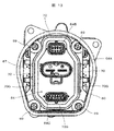
- FIG. 13 shows a state as seen from the connector assembly side with the metal cover removed
- FIG. 14 shows a state as seen obliquely from the upper side. Note that FIG. 13 shows a state before being filled with the liquid sealing agent.
- the electronic control unit is arranged on the end face portion 61 of the motor housing 60, and the power conversion circuit unit (not shown), the power supply circuit unit 62, the control circuit unit 63, and the connector assembly are sequentially arranged from the end face unit 61.
- the solid 64 is arranged.
- the mounting substrate 65 of the power supply circuit unit 62 is fixed to the stepped portion of the end face portion 61 with a fixing bolt 66.
- the mounting board 67 of the control circuit portion 63 and the connector assembly 64 are fixed together by a fixing bolt 69 to a fixing portion 68 that is erected from the end surface portion 61.
- An annular seal accommodating portion 70 is formed around the external terminal forming portion of the connector assembly 64, and a liquid sealing agent 71 is filled inside.
- the annular seal accommodating portion 70 is formed in a continuous groove-shaped concave portion 70G (see FIG. 13) in order to store the liquid sealing agent 71. As shown in FIG. 14, the liquid sealant 71 is filled and stored in the recess 70G.
- the external terminal forming portions 64A to 64C of the connector assembly 64 are exposed to the outside through the exposure holes formed in the bottom surface of the metal cover. That is, the bottom surface portion formed on one end side of the side peripheral surface portion of the metal cover is provided with an exposure hole for exposing the external terminal forming portions 64A to 64C of the connector assembly 64 to the outside.
- the exposed hole is formed by punching on the bottom surface portion by a punch, and the peripheral portion of the exposed hole is formed with an annular reinforcing protrusion bent inside the metal cover.
- the annular reinforcing protrusion formed on the peripheral portion of the exposed hole is formed in the same shape as the annular seal accommodating portion 70 so as to be accommodated in the annular seal accommodating portion 70. Therefore, the liquid tight function is ensured by the annular seal accommodating portion 70, the liquid sealing agent 71, and the annular reinforcing protrusion.
- An object of the present invention is to provide a novel electric drive device and electric power steering device equipped with an inexpensive locking mechanism.
- a motor housing in which an electric motor for driving the mechanical control elements is housed,
- An electronic control unit provided on an end surface portion of the motor housing opposite to the output portion of the rotating shaft of the electric motor,
- a connector assembly provided on the opposite side of the end surface portion of the motor housing of the electronic control unit;
- An annular seal accommodating portion formed around the external terminal forming portion of the connector assembly and filled with a liquid sealing agent;
- a fixing member for fixing the connector assembly to a fixing portion of an end surface portion of the motor housing, A liquid sealant guide passage formed in the annular seal containing part for flowing the liquid sealant filled in the annular seal containing part into the fixing member;
- An exposure hole that covers the electronic control portion from the outside and exposes the external terminal forming portion to the outside, and a bottom surface portion that has an annular reinforcing projection portion that is formed in a peripheral portion of the exposure hole and that is housed in the annular seal housing portion, And a side peripheral surface portion that is bent from the bottom surface portion and has an opening formed to be fixed
- the fixing member and the connector assembly are fixed to each other by the liquid sealing agent.
- the liquid sealing agent filled between the annular reinforcing outlet and the annular seal accommodating portion.
- FIG. 1 is an overall perspective view showing the overall shape of an electric power steering device according to an embodiment of the present invention.
- FIG. 3 is an exploded perspective view of the electric power steering device shown in FIG. 2. It is a perspective view of the motor housing shown in FIG.
- FIG. 5 is a cross-sectional view of the motor housing shown in FIG. 4 taken along the axial direction. It is a perspective view which shows the state which mounted and fixed the electric power conversion circuit part in the motor housing shown in FIG.
- FIG. 7 is a perspective view showing a state where a power supply circuit unit is placed and fixed on the motor housing shown in FIG. 6.
- FIG. 8 is a perspective view showing a state where a control circuit unit is placed and fixed on the motor housing shown in FIG. 7.
- FIG. 9 is a perspective view showing a state where the connector assembly is placed and fixed on the motor housing shown in FIG. 8.
- FIG. 3 is an enlarged cross-sectional view in which the vicinity of the electronic control unit in the state where the metal cover of the electric power steering device according to the embodiment of the present invention is attached is enlarged. It is the top view seen from the connector assembly side in the state which removed the metal cover of the electric power steering apparatus shown in FIG. It is the perspective view which looked at the electric power steering device shown in FIG. 11 from diagonally upward. It is the top view seen from the connector assembly side in the state where the metal cover of the conventional electric power steering device was removed. It is the perspective view which looked at the electric power steering apparatus shown in FIG. 13 from diagonally upward.
- the steering device 1 is configured as shown in FIG.
- a pinion (not shown) is provided at the lower end of the steering shaft 2 connected to a steering wheel (not shown), and this pinion meshes with a rack (not shown) that is long in the lateral direction of the vehicle body.
- Tie rods 3 for steering the front wheels to the left and right are connected to both ends of the rack, and the rack is covered with a rack housing 4.
- a rubber boot 5 is provided between the rack housing 4 and the tie rod 3.
- An electric power steering device 6 is provided to assist the torque when rotating the steering wheel. That is, the torque sensor 7 that detects the rotation direction and the rotation torque of the steering shaft 2 is provided, and the electric motor unit 8 that applies the steering assist force to the rack via the gear 10 based on the detection value of the torque sensor 7. And an electronic control unit (ECU) 9 for controlling the electric motor arranged in the electric motor unit 8.
- ECU electronice control unit
- the electric motor unit 8 of the electric power steering device 6 is connected to the gear 10 through three bolts (not shown) on the outer peripheral portion on the output shaft side, and the electronic control unit 9 is provided on the side opposite to the output shaft of the electric motor 8 unit. Is provided.
- the torque sensor 7 indicates the rotation direction and the rotation torque of the steering shaft 2.
- the control circuit section calculates the drive operation amount of the electric motor based on the detected value.
- the electric motor is driven by the power switching element of the power conversion circuit unit, and the output shaft of the electric motor is rotated so as to drive the steering shaft 2 in the same direction as the operation direction.
- the rotation of the output shaft is transmitted from a pinion (not shown) to a rack (not shown) via the gear 10 to steer the vehicle. Since their configurations and operations are already well known, further description will be omitted.
- the fixing bolt 69 for fixing the mounting board 67 of the connector assembly 64 and the control circuit section 63 to the fixing section 68 prevents loosening. To do so, it is necessary to use a fixing bolt with a locking function. However, since the fixing bolt having the lock function has a high unit price, the use of this fixing bolt inevitably increases the unit price of the product, which causes a problem that the competitiveness of the product is deteriorated.
- the present invention proposes an electric power steering device having the following configuration.
- the electronic control unit provided on the end surface portion of the motor housing on the side opposite to the output portion of the rotating shaft of the electric motor, and the connector provided on the side opposite to the end surface portion of the motor housing of the electronic control unit.
- the liquid sealant guide passage formed in the annular seal containing part for flowing the liquid sealant filled in the annular seal containing part to the fixing member and the electronic control part are covered from the outside to expose the external terminal forming part to the outside.
- An exposure hole a bottom surface portion having an annular reinforcing protrusion formed in a peripheral portion of the exposure hole and housed in the annular seal housing portion, and an end surface portion of the motor housing bent from the bottom surface portion. And configured to include a metal cover and a side peripheral surface portion forming an opening to be constant.
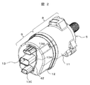
- FIG. 2 is a diagram showing the overall configuration of the electric power steering device according to the present embodiment
- FIG. 3 is a diagram showing the components of the electric power steering device shown in FIG. 4 to 9 are views showing a state in which the respective constituent parts are assembled according to the assembling order of the respective constituent parts.
- FIG. 10 is a drawing showing a cross section of an electronic control unit of the electric power steering apparatus
- FIG. 11 shows a cross section of a metal cover
- FIG. 12 shows a state in which the metal cover is viewed from diagonally above
- FIG. The section of the electronic control part of the electric power steering device with which the cover was attached is shown. Therefore, in the following description, the description will be given with appropriate reference to the drawings.
- the electric motor unit 8 constituting the electric power steering apparatus has a motor housing 11 having a cylindrical portion made of aluminum or an aluminum-based metal such as an aluminum alloy, and a housing (not shown) housed therein.
- the electronic control unit 9 is composed of an electric motor, and the electronic control unit 9 is made of an aluminum-based metal such as aluminum or an aluminum alloy, or an iron-based metal, which is disposed on the opposite side of the motor housing 11 from the output shaft in the axial direction. It is composed of a metal cover 12 and an electronic control assembly (not shown) housed in the metal cover 12.
- the motor housing 11 and the metal cover 12 are integrally fixed by "crimping and fixing” in the fixing region formed on the opposing end faces in the outer peripheral direction.
- the electronic control assembly housed inside the metal cover 12 has a power supply circuit unit that generates a necessary power supply, a MOSFET that drives and controls an electric motor of the electric motor unit 8, or a power switching device that includes an IGBT or the like. It is composed of a conversion circuit and a control circuit section for controlling this power switching element, and the output terminal of the power switching element and the coil input terminal of the electric motor are electrically connected via a bus bar.
- a part of the connector assembly 13 is exposed from an exposure hole 42 formed in the metal cover 12 on the end surface of the metal cover 12 on the side opposite to the motor housing 11.
- the connector assembly 13 is fixed to a fixing portion formed on the end surface of the motor housing 11 with a fixing bolt that is a fixing member.
- an external terminal forming portion 13A for power supply, an external terminal forming portion 13B for a detection sensor, and an external terminal forming portion 13C for sending a control state to send a control state to an external device are provided. I have it.
- the electronic control assembly housed in the metal cover 12 is supplied with electric power from the power supply through the external terminal forming portion 13A for supplying electric power, which is made of synthetic resin, and the detection sensors detect the operating state and the like.
- the signal is supplied through the external terminal forming portion 13B for the detection sensor, and the current control state signal of the electric power steering device is transmitted through the external terminal forming portion 13C for transmitting the control state.
- Fig. 3 shows the electric power steering device 6 disassembled and viewed from an angle.
- An annular iron side yoke (not shown) is fitted inside the motor housing 11, and an electric motor (not shown) is housed in the side yoke.
- the output unit 14 of the electric motor applies a steering assist force to the rack via a gear. Since the specific structure of the electric motor is well known, its explanation is omitted here.
- the motor housing 11 is made of an aluminum alloy, and functions as a heat sink member that releases the heat generated by the electric motor and the heat generated by the power supply circuit section and the power conversion circuit section described later to the outside atmosphere.
- the electric motor and the motor housing 11 constitute the electric motor unit 8.
- An electronic control unit EC is attached to the end surface portion 15 of the motor housing 11 on the side opposite to the output portion 14 of the electric motor portion 8.
- the electronic control unit EC includes a power conversion circuit unit 16, a power supply circuit unit 17, a control circuit unit 18, and a connector assembly 13.
- the end surface portion 15 of the motor housing 11 is formed integrally with the motor housing 11. However, in addition to this, only the end surface portion 15 may be separately formed and integrated with the motor housing 11 by bolts or welding. Is.
- the power conversion circuit unit 16, the power conversion circuit unit 17, and the control circuit unit 18 form a redundant system, and form a dual system of a main electronic control unit and a sub electronic control unit.
- the electric motor is usually controlled and driven by the main electronic control unit.
- the sub electronic control unit is switched to control and drive the electric motor. Therefore, as will be described later, when heat from the main electronic control unit is normally transferred to the motor housing 11 and an abnormality or failure occurs in the main electronic control unit, the main electronic control unit stops and the sub electronic control unit operates. The heat from the sub electronic control unit is transmitted to the motor housing 11.
- the main electronic control unit and the sub electronic control unit are combined to function as a regular electronic control unit, and when one electronic control unit is abnormal or malfunctions, the other electronic control unit is controlled. It is also possible to control and drive the electric motor with half the capacity. In this case, the capacity of the electric motor is halved, but the so-called "power steering function" is ensured. Therefore, in the normal case, the heat of the main electronic control unit and the heat of the sub electronic control unit are transferred to the motor housing 11.
- the electronic control unit EC includes a control circuit unit 18, a power supply circuit unit 17, a power conversion circuit unit 16, and a connector assembly 13, and the power conversion circuit unit 16 and the power supply circuit are arranged in a direction away from the end face portion 15 side.
- the portion 17, the control circuit portion 18, and the connector assembly 13 are arranged in this order.
- the control circuit unit 18 generates a control signal for driving the switching elements of the power conversion circuit unit 16, and is composed of a microcomputer, peripheral circuits, and the like.
- the power supply circuit unit 17 generates a power supply for driving the control circuit unit 18 and a power supply for the power conversion circuit unit 16, and is composed of a capacitor, a coil, a switching element, and the like.
- the power conversion circuit unit 16 adjusts the power flowing through the coil of the electric motor, and is composed of a switching element or the like that constitutes upper and lower arms of three phases.
- the heat generation amount in the electronic control unit EC is large mainly in the power conversion circuit unit 16 and the power supply circuit unit 17, and the heat of the power conversion circuit unit 16 and the power supply circuit unit 17 is radiated from the motor housing 11 made of aluminum alloy. Is done. This detailed configuration will be described later with reference to FIGS. 4 to 9.
- a connector assembly 13 made of synthetic resin is provided between the control circuit section 18 and the metal cover 12, and is connected to a vehicle battery (power source) or another external control device (not shown). Needless to say, the connector assembly 13 is connected to the power conversion circuit unit 16, the power supply circuit unit 17, and the control circuit unit 18.
- the metal cover 12 has a function of accommodating the power conversion circuit unit 16, the power supply circuit unit 17, and the control circuit unit 18, covering them from the outside and sealing them in a liquid-tight manner. Is fixed to the motor housing 11 by caulking and fixing.
- the metal cover 12 includes a side peripheral surface portion 43 and a bottom surface portion 44 formed by being bent from one end of the side peripheral surface portion 43.
- the bottom surface portion 44 includes the external terminal forming portion 13A of the connector assembly 13.
- An exposure hole 42 that exposes 13B and 13C to the outside is opened.
- An opening end 37 is formed on the opposite side of the bottom surface portion 44, and the opening end 37 is engaged with the end surface portion 15 of the motor housing 11.
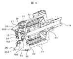
- FIG. 4 shows the appearance of the motor housing 11, and FIG. 5 shows its axial section.
- the motor housing 11 is formed in a tubular shape and closes the side peripheral surface portion 11A, the end surface portion 15 that closes one end of the side peripheral surface portion 11A, and the other end of the side peripheral surface portion 11A. It is composed of the end surface portion 19.
- the motor housing 11 has a bottomed cylindrical shape, and the side peripheral surface portion 11A and the end surface portion 15 are integrally formed. Further, the end surface portion 19 has a function of a lid and closes the other end of the side peripheral surface portion 11A after the electric motor is housed in the side peripheral surface portion 11A.
- annular step portion 35 having a diameter reduced inward in the radial direction is formed on the end surface peripheral surface of the end surface portion 15, and the open end 37 of the metal cover 12 shown in FIG. 9 engages with this step portion 35. It is a thing.
- the fixing form of the side wall of the end face portion 15 and the opening end 37 of the metal cover 12 is a so-called "crimp fixing".
- a stator 21 having a coil 20 wound around an iron core is fitted inside the side peripheral surface portion 11A of the motor housing 11, and a permanent magnet is embedded inside the stator 21.
- the rotor 22 is rotatably housed.
- a rotation shaft 23 is fixed to the rotor 22, one end of which serves as the output unit 14, and the other end of which serves as a rotation detection unit 24 for detecting the rotation phase and the rotation speed of the rotation shaft 23.
- the rotation detector 24 is provided with a permanent magnet, which penetrates the through hole 25 provided in the end face portion 15 and projects to the outside. Then, the rotational phase and the rotational speed of the rotary shaft 23 are detected by a magnetic sensing unit (not shown) such as a GMR element.
- the electric power of the power conversion circuit unit 16 (see FIG. 3) and the power supply circuit unit 17 (see FIG. 3) is provided on the surface of the end surface portion 15 located on the side opposite to the output portion 14 of the rotary shaft 23.
- a heat radiation area for conversion 15A and a heat radiation area for power supply 15B are formed.
- Substrate / connector fixing protrusions 26 are integrally planted at the four corners of the end face portion 15, and screw holes 26S are formed inside.
- the board / connector fixing convex portion 26 is provided for fixing the control circuit portion 18 described later and the connector assembly 13.
- a board receiving portion 27 is formed on the board fixing convex portion 26 erected from the power conversion heat radiation area 15A, which will be described later, and has the same height in the axial direction as the power supply heat radiation area 15B, which is also described later.
- the board receiving portion 27 is for mounting and fixing a glass epoxy board 31, which is a mounting board for the power supply circuit section 17, which will be described later.
- the plane area in the radial direction that is orthogonal to the rotation axis 23 and forms the end surface portion 15 is divided into two.
- One forms a power conversion heat dissipation area 15A to which a power conversion circuit section 16 composed of a switching element such as a MOSFET is attached, and the other forms a power supply heat dissipation area 15B to which a power supply circuit section 17 is attached.
- the power conversion heat dissipation area 15A is formed to have a larger area than the power supply heat dissipation area 15B. This is to secure the installation area of the power conversion circuit unit 16 because the dual system is adopted as described above.
- the power conversion heat dissipation area 15A and the power supply heat dissipation area 15B have steps having different heights in the axial direction (direction in which the rotary shaft 23 extends). That is, the heat radiation area 15B for power supply is formed with a step in the direction away from the heat radiation area 15A for power conversion when viewed in the direction of the rotating shaft 23 of the electric motor. This step is set to a length such that the power conversion circuit unit 16 and the power supply circuit unit 17 do not interfere with each other when the power supply circuit unit 17 is installed after the power conversion circuit unit 16 is installed.
- the projecting heat radiating section 28 is provided with a dual system power conversion circuit section 16 to be described later. Further, the projecting heat dissipation portion 28 extends so as to project in a direction away from the electric motor when viewed in the direction of the rotating shaft 23 of the electric motor.
- the heat radiation area 15B for power supply is flat and is provided with a power supply circuit section 17 described later. Therefore, the projecting heat dissipation portion 28 functions as a heat dissipation portion that transfers the heat generated in the power conversion circuit portion 16 to the end surface portion 15, and the power supply heat dissipation area 15B transmits the heat generated in the power supply circuit portion 17 to the end surface portion 15. It functions as a heat dissipation part that transfers heat.
- the projecting heat dissipation portion 28 can be omitted, and in this case, the power conversion heat dissipation area 15A functions as a heat dissipation portion that transfers the heat generated in the power conversion circuit portion 16 to the end surface portion 15.
- the metal substrate of the power conversion circuit unit 16 is welded to the projecting heat radiating unit 28 by friction stir welding to achieve reliable fixation.
- the heat sink member can be omitted and the axial length can be shortened. Further, since the motor housing 11 has a sufficient heat capacity, the heat of the power supply circuit section 17 and the power conversion circuit section 16 can be efficiently radiated to the outside.
- FIG. 6 shows a state in which the power conversion circuit unit 16 is installed in the projecting heat dissipation unit 28 (see FIG. 4).
- the power conversion circuit unit 16 of a dual system is installed above the projecting heat dissipation unit 28 (see FIG. 4) formed in the power conversion heat dissipation region 15A.
- the switching element forming the power conversion circuit unit 16 is mounted on a metal substrate (here, an aluminum-based metal is used), and is configured to easily dissipate heat.
- the metal substrate is welded to the projecting heat dissipation portion 28 by friction stir welding.
- the metal substrate is firmly fixed to the projecting heat dissipation portion 28 (see FIG. 4), and the heat generated in the switching element can be efficiently transferred to the projecting heat dissipation portion 28 (see FIG. 4).
- the heat transmitted to the projecting heat dissipation portion 28 (see FIG. 4) is diffused to the power conversion heat dissipation area 15A and further transferred to the side peripheral surface portion 11A of the motor housing 11 to be dissipated to the outside.
- the axial height of the power conversion circuit section 16 is lower than the height of the power radiation area 15B, it does not interfere with the power circuit section 17 described later.
- the power conversion circuit section 16 is installed above the projecting heat dissipation section 28 formed in the power conversion heat dissipation area 15A. Therefore, the heat generated in the switching element of the power conversion circuit section 16 can be efficiently transferred to the projecting heat dissipation section 28. Further, the heat transmitted to the projecting heat dissipation portion 28 is diffused into the power conversion heat dissipation area 15A, transferred to the side peripheral surface portion 11A of the motor housing 11, and dissipated to the outside.
- FIG. 7 shows a state in which the power supply circuit unit 17 is installed from above the power conversion circuit unit 16.
- the power supply circuit section 17 is installed above the power supply heat dissipation area 15B.
- the capacitor 29, the coil 30, and the like that form the power supply circuit unit 17 are mounted on the glass epoxy substrate 31.
- the power supply circuit unit 17 also employs a dual system, and as can be seen from the drawing, the power supply circuits each including the capacitor 29, the coil 30, etc. are symmetrically formed.
- electric elements such as capacitors other than the switching elements of the power conversion circuit unit 16 are mounted.
- the surface of the glass epoxy substrate 31 on the power radiation area 15B (see FIG. 6) side is fixed to the end face portion 15 so as to be in contact with the power radiation area 15B.
- a fixing bolt (not shown) is fixed to a screw hole 27S provided in the substrate receiving portion 27 of the substrate fixing convex portion 26. Further, it is also fixed to a screw hole provided in the power radiation area 15B (see FIG. 6) by a fixing bolt (not shown).
- the power supply circuit section 17 is formed of the glass epoxy board 31, double-sided mounting is possible. Then, on the surface of the glass epoxy substrate 31 on the side of the heat radiation area 15B for power supply (see FIG. 6), a rotation phase and rotation speed detection section including a GMR element and a detection circuit thereof (not shown) are mounted, and the rotation shaft 23 ( The rotation phase and the number of rotations of the rotation are detected in cooperation with the rotation detector 24 (see FIG. 5) (see FIG. 5).
- the heat generated in the power circuit section 17 can be efficiently used for the heat radiation area 15B for power supply (FIG. 6). See) can transfer heat.
- the heat transferred to the power radiation area 15B (see FIG. 6) is diffused to the side peripheral surface portion 11A of the motor housing 11 and transferred to the outside to be radiated.
- any one of an adhesive, a heat radiation grease, and a heat radiation sheet having a good heat transfer property is interposed to further improve the heat transfer performance. Can be improved.
- the power supply circuit section 17 is installed above the power supply heat dissipation area 15B.
- the surface of the glass epoxy substrate 31 on which the circuit elements of the power supply circuit section 17 are mounted on the side of the heat radiation area 15B for power supply is fixed to the end surface portion 15 so as to be in contact with the heat radiation area 15B for power supply. Therefore, the heat generated in the power supply circuit section 17 can be efficiently transferred to the power supply heat dissipation area 15B.
- the heat transferred to the power radiation area 15B is diffused and transferred to the side peripheral surface portion 11A of the motor housing 11 to be radiated to the outside.
- FIG. 8 shows a state in which the control circuit unit 18 is installed from above the power supply circuit unit 17.
- a control circuit unit 18 is installed above the power supply circuit unit 17.
- the microcomputer 32 and the peripheral circuit 33 that form the control circuit unit 18 are mounted on a glass epoxy substrate 34 that is a mounting substrate.
- the control circuit unit 18 also employs a dual system, and as can be seen from the drawing, control circuits each including a microcomputer 32 and a peripheral circuit 33 are symmetrically formed.
- the microcomputer 32 and the peripheral circuit 33 may be provided on the surface of the glass epoxy board 34 on the side of the power supply circuit section 17.
- the glass epoxy board 34 is fixed by a fixing bolt (not shown) in a form of being sandwiched by the connector assembly 13 in a screw hole provided at the top of the board fixing convex portion 26 (see FIG. 7).
- FIG. 9 shows a state in which the connector assembly 13 is installed from above the control circuit unit 18.
- the connector assembly 13 is installed above the control circuit unit 18.
- the connector assembly 13 is fixed by fixing bolts 36 so that the glass epoxy board 34 of the control circuit section 18 is sandwiched between the screw holes 26S provided at the top of the board fixing convex portion 26.
- the connector assembly 13 is electrically connected to the power conversion circuit unit 16, the power supply circuit unit 17, and the control circuit unit 18 as shown in FIG.
- annular seal accommodating portion 45 having a groove-shaped cross section in the axial direction is formed around the external terminal forming portions 13A, 13B, and 13C of the connector assembly 13.
- a liquid sealant is filled in the annular seal accommodating portion 45, and an annular reinforcing protrusion 46 formed in the exposure hole 42 of the metal cover 12, which will be described later, further enters and is accommodated. Therefore, liquid tightness is secured between the metal cover 12 and the connector assembly 13 by the annular seal accommodating portion 45, the liquid sealing agent, and the annular reinforcing protrusion 46.
- the open end 37 of the metal cover 12 is engaged with the step portion 35 of the motor housing 11, and is fixed by caulking and fixing in a fixing region provided in the outer peripheral direction.
- the annular step portion 35 on the motor housing side formed on the end peripheral surface of the end surface portion 15 and the opening end 37 of the metal cover 12 are in a form called “inlet engagement” or “inlet fitting”. Engaged.
- FIG. 10 shows an enlarged cross-sectional view of the vicinity of the electronic control unit of the electric power steering device according to the present embodiment.
- a power conversion circuit portion 16, a power supply circuit portion 17, and a control circuit portion 18, which form an electronic control portion, are provided in such a manner that they are sequentially stacked in a direction away from the end surface portion 15. ing. Further, the connector assembly 13 is disposed on the side of the control circuit unit 18 opposite to the power supply circuit unit 17. However, the power conversion circuit unit 16, the power supply circuit unit 17, and the control circuit unit 18 may be arranged in any order, and the point is that the electronic control unit should be arranged between the connector assembly 13 and the end face portion 15. It is a thing.
- a plurality of caulking fixing portions are formed on the side surface of the step portion 35 of the end surface portion 15 to which the opening end 37 of the metal cover 12 is fixed.
- the caulking fixing portion is a caulking groove or a caulking hole formed in a fixing wall axially extending from the annular step portion 35 formed in the end surface portion 15 of the motor housing 11 toward the connector assembly 13 side.
- the metal cover 12 is fixed by pushing the wall surface of the metal cover 12 into the caulking concave portion made of the like by a pushing tool, plastically deforming and caulking.
- the annular space G formed by the open end 37 of the metal cover 12 and the wall surface extending from the annular step portion 35 to the fixed wall is filled with a liquid sealing agent for liquid tightness without a gap. Therefore, a liquid-tight seal area is formed between the end surface portion 15 and the open end 37 of the metal cover 12, so that water or the like is prevented from entering the seal area. For this reason, since moisture or the like does not enter the caulking and fixing portion, it is possible to suppress corrosion of the caulking and fixing portion and improve mechanical reliability. Furthermore, since the intrusion of water and the like into the electronic control unit 9 is suppressed, it is possible to improve the electrical reliability as well.
- the caulking recesses having a predetermined length are formed so as to be scattered at necessary places (3 places), and the metal cover 12 is pushed by the caulking recesses so that the metal cover 12 is Movement of the motor housing 11 in the rotation direction and movement of the rotation shaft 23 in the axial direction are suppressed.
- annular seal accommodating portion 45 is formed in an annular groove shape on the surface of the facing surface 47 facing the bottom surface portion 44 in a state where the connector assembly 13 faces the bottom surface portion 44 of the metal cover 12. ..
- the groove has a rectangular cross section or a semicircular cross section. A shape such as an arc shape can be adopted.
- the groove-shaped annular seal accommodating portion 45 is an annular groove that is open on the side opposite to the end surface portion 15 of the motor housing 11 in the axial direction of the rotary shaft 23. Therefore, the annular groove is formed along the axis of the rotary shaft 23.
- the annular seal accommodating portion 45 is filled with a liquid sealant 48 for ensuring liquid tightness when the metal cover 12 is assembled. Further, the depth of the groove forming the annular seal accommodating portion 45 is determined by the length of the annular reinforcing protrusion 46 formed on the peripheral portion of the exposure hole 42 of the metal cover 12 described later.
- the metal cover 12 includes a side peripheral surface portion 43 and a bottom surface portion 44 formed by bending from one end of the side peripheral surface portion 43, and the bottom surface portion 44 has a connector assembly.
- An exposure hole 42 for exposing the external terminal forming portions 13A, 13B, 13C of the three-dimensional body 13 to the outside is opened.
- An opening end 37 is formed on the opposite side of the bottom surface portion 44, and the opening end 37 is engaged with the end surface portion 15 of the motor housing 11.
- An exposure hole 42 for exposing the external terminal forming portions 13A, 13B, 13C of the connector assembly 13 to the outside is formed in the vicinity of the center of the bottom surface portion 44, and a peripheral portion (in other words, a peripheral portion forming the exposure hole 42) is formed.
- the inner peripheral end surface for forming the exposed hole 42 of the bottom surface portion 44 is formed with an annular reinforcing protrusion 46 (see FIG. 10) that is bent toward the inside of the metal cover 12.
- the annular reinforcing protrusion 46 can be formed by drawing the metal cover 12.
- the annular reinforcing protrusion 46 has a shape along the axis of the rotary shaft 23 in a state where the metal cover 12 is incorporated in the end surface portion 15, and accordingly, is positioned along the groove of the annular seal accommodating portion 45. .. That is, the side wall forming the groove of the annular seal accommodating portion 45 and the annular reinforcing protrusion 46 are in a substantially parallel positional relationship.
- the axial length of the annular reinforcing protrusion 46 is determined so as not to be in close contact with the bottom surface of the groove forming the annular seal accommodating portion 45 described above. As a result, it is possible to allow a margin in the axial dimension management of the annular reinforcing protrusion 46 and the annular seal accommodating portion 45. Further, a liquid sealing agent can be interposed between the annular reinforcing protrusion 46 and the inner wall surface of the annular seal accommodating portion 45, so that the liquid tight function can be ensured.
- the liquid sealant 48 is filled in advance inside the annular seal accommodating portion 45 formed in the connector assembly 13.
- the liquid sealant 48 has fluidity before being hardened, and can flow relatively easily by gravity or its own weight. Then, when the metal cover 12 is assembled so as to cover the electronic control unit 9, the annular reinforcing protrusion 46 formed on the bottom surface portion 44 of the metal cover 12 is inserted into the annular seal accommodating portion 45 formed on the connector assembly 13. Will be stored.
- the wall surface of the metal cover 12 is plastically deformed by pressing the tool against the caulking concave portion of the metal cover 12, and the caulking fixing portion is caulked and fixed.
- an external force due to the caulking may act on the metal cover 12 and deform the vicinity of the exposed hole 42 of the metal cover 12, but in the present embodiment, the annular reinforcing protrusion 46 is formed.
- the mechanical strength in the vicinity of the exposure hole 42 can be increased, and the deformation in the vicinity of the exposure hole 42 and the metal cover 12 can be suppressed.
- the annular reinforcing protrusion 46 is accommodated in the annular seal accommodating portion 45 with a predetermined gap from the inner wall surface of the annular seal accommodating portion 45, the liquid sealing agent is accommodated in this gap. 48 is filled. Therefore, sufficient liquid tightness can be secured in this portion.
- the outer surface of the liquid sealant 48 located on the inner peripheral side of the annular reinforcing protrusion 46 exceeds the surface of the bottom surface portion 44 of the metal cover 12, and is additionally filled by a thickness (t).
- annular reinforcing protrusion 46 is formed on the peripheral edge of the exposure hole 42 formed on the bottom surface 44 of the metal cover 12, the mechanical strength around the exposure hole 42 can be increased. Accordingly, even when an external force is applied to the metal cover 12 in the assembling process of the metal cover or the actual use process, it is possible to suppress the deformation of the periphery of the exposure hole 42 and the deformation of the metal cover 12.
- the metal cover 12 is caulked and fixed to the end surface portion 15 of the motor housing 11, but the external force associated with the caulking operation at this time acts on the exposure hole 42 of the metal cover 12 and the exposure hole 42 is exposed.
- the event that the peripheral region is deformed occurred, the event that the peripheral region of the exposure hole 42 was deformed could be avoided by forming the above-described annular reinforcing protrusion 46.
- the annular seal accommodating portion 45 formed around the external terminal forming portions 13A, 13B and 13C of the connector assembly 13 is accommodated in the peripheral portion of the exposure hole 42 formed in the bottom surface portion 44 of the metal cover 12. Since the annular reinforcing protrusion 46 is formed, the mechanical strength of the peripheral region of the exposure hole 42 can be improved and the deformation of the metal cover 12 can be suppressed.
- annular reinforcing protrusion 46 is formed by drawing the metal cover 12 in the present embodiment, a separate reinforcing protrusion is fixed to the bottom surface 44 of the metal cover 12 by welding, forging, or the like. It can also be fixedly formed by means. Further, although the annular reinforcing protrusion 46 is also formed with the exposure hole 42, an annular reinforcing protrusion having a shape along the annular seal accommodating portion 45 may be formed on the outer peripheral side of the exposure hole 42.
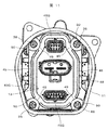
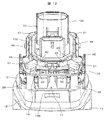
- FIGS. 11 and 12 show a state as viewed from the connector assembly side with the metal cover removed
- FIG. 12 shows a state as viewed obliquely from above. Note that FIG. 11 shows a state before the liquid sealant is filled.
- an electronic control unit is arranged on the end face portion 15 of the motor housing 11, and a power conversion circuit unit (not shown), a power supply circuit unit 17, a control circuit unit 18, and a connector assembly are arranged in order from the end face unit 15.
- the three-dimensional body 13 is arranged. Further, the glass epoxy board 31 of the power supply circuit section 17 is fixed to the step portion of the end surface section 15 with a fixing bolt. Further, the glass epoxy board 34 of the control circuit section 18 and the connector assembly 13 are fixed together by the fixing bolts 36 to the board fixing convex portion 26 erected from the end surface portion 15.
- An annular seal accommodating portion 45 is formed around the external terminal forming portion of the connector assembly 13, and a liquid sealant 48 is filled inside.
- the annular seal accommodating portion 45 is basically formed in a continuous groove-shaped annular recess 45G for storing the liquid sealing agent 48. For example, it is formed on the inside of an annular wall surface that rises from the surface around the screwing region 50 in which an insertion hole for inserting the fixing bolt 36 is formed.
- the external terminal forming portions 13A to 13C of the connector assembly 13 are exposed to the outside through the exposure holes 42 formed in the bottom surface portion 44 of the metal cover 12, as shown in FIG. That is, the bottom surface portion 44 formed on one end side of the side peripheral surface portion 43 of the metal cover 12 is formed with the exposure hole 42 for exposing the external terminal forming portions 13A to 13C of the connector assembly 13 to the outside.
- the exposure hole 42 is formed by punching the bottom surface portion 44 with a punch, and an annular reinforcing protrusion 46 is formed on the periphery of the exposure hole by being bent inward of the metal cover. Note that FIG. 13 shows a state before being filled with the liquid sealing agent.
- the annular reinforcing protrusion 46 formed on the peripheral portion of the exposure hole 42 is formed in the same shape as the annular seal accommodating portion 45 so as to be accommodated in the annular recess 45G of the annular seal accommodating portion 45. Therefore, the liquid tight function is ensured by the annular seal accommodating portion 45, the liquid sealant 48, and the annular reinforcing protrusion 46.
- the wall surface portion of the annular recess 45G forming the annular seal accommodating portion 45 adjacent to the fixing bolt 36 is cut out to form a liquid sealant guide passage 49.
- the liquid sealant guide passage 49 is provided corresponding to each fixing bolt 36. It is desirable that the liquid sealant guide passage 49 be provided in the wall surface portion of the annular recess 45G closest to the peripheral surface of the head of the fixing bolt 36.
- the liquid sealant guide passage 49 has a function of fluidly connecting the vicinity of the head of the fixing bolt 36 and the annular recess 45G forming the annular seal accommodating portion 45.
- the fixing bolt 36 is inserted into the through holes formed in the screwing regions 50 formed at the four corners of the facing surface 47 of the connector assembly 13 and screwed to the board fixing convex portion 26.
- the screwing region 50 is below the annular recess 45G of the annular seal accommodating portion 45, that is, the end surface of the motor housing 11 when viewed with the electronic control unit on the upper side. It is formed on the portion 15 side.
- the liquid sealant 48 filled in the annular recess 45G forming the annular seal accommodating portion 45 flows out of the liquid sealant guide passage 49 due to gravity and its own weight and reaches the screw fastening region 50.
- the liquid sealant 48 has fluidity before being hardened, and therefore covers the entire head of the fixing bolt 36 or a part thereof, and after that, It is hardened by a hardening treatment to form a locking portion 51 for fixing the surface of the screw fastening region 50 and the entire head of the fixing bolt 36 or a part thereof to each other.
- the hardened liquid sealant 48 has adhesiveness, so that even if the fixing bolt 36 rotates in the loosening direction due to vibration or the like, the screwing region 50 and the liquid sealant 48 prevent the fixing bolt 36 from rotating. It is effective in preventing loosening.
- the liquid sealant guide passage 49 is formed by cutting out the wall surface of the annular recess 45G forming the annular seal accommodating portion 45, but a through hole is formed in the wall surface of the annular recess 45G.
- the liquid sealant 48 for liquid tightness filled between the metal cover 12 and the connector assembly 13 is made of an adhesive synthetic resin. In this embodiment, it is room temperature cured or heat cured.
- a silicone rubber-based elastic adhesive is used. This silicone rubber-based elastic adhesive has a property of absorbing stress such as external vibration and impact and making it difficult for stress to concentrate on the bonding interface. For this reason, in a device such as an electric power steering device that is subject to vibration, impact, etc., the adhesive interface may be peeled off and the liquid-tight function may be lost. The risk of loss of dense function can be reduced.
- the liquid sealing agent 48 having adhesiveness is used for sealing, it is possible to omit the conventionally used O-ring for liquid tightness.
- the liquid sealant 48 may be a liquid gasket (FIPG: FORMED IN PLACE GASKET) having an adhesive function, and may be made of a material that is cured at room temperature or heat.
- the bolts are used as the fixing members in the embodiments, it goes without saying that the bolts are not limited to the bolts and may be rivets.
- the present invention provides a motor housing in which an electric motor for driving a mechanical system control element is housed, and an electronic control provided on the end surface portion of the motor housing opposite to the output portion of the rotary shaft of the electric motor.
- Section a connector assembly provided on the side opposite to the end surface of the motor housing of the electronic control section, and an annular seal accommodating section formed around the external terminal forming section of the connector assembly and filled with a liquid sealing agent.
- An exposure hole that covers the passage, the electronic control portion from the outside, and exposes the external terminal formation portion to the outside, and an annular reinforcing protrusion that is formed in the peripheral portion of the exposure hole and is accommodated in the annular seal accommodation portion.
- a bottom portion having a section, and a metal cover and a side peripheral surface portion forming an opening which is fixed to the end face of the motor housing is bent from the bottom portion, and characterized in that.
- the present invention is not limited to the above-described embodiments, but includes various modifications.
- the above-described embodiments have been described in detail in order to explain the present invention in an easy-to-understand manner, and are not necessarily limited to those having all the configurations described.
- a part of the configuration of a certain embodiment can be replaced with the configuration of another embodiment, and the configuration of another embodiment can be added to the configuration of a certain embodiment.
- other configurations can be added / deleted / replaced.
- Coil 31 ... Glass epoxy board, 32 ... Microcomputer , 33 ... Peripheral circuit, 34 ... Glass epoxy substrate, 35 ... Step part, 36 ... Fixing bolt, 37 ... Opening end, 38 ... Crimping fixing part, 39 ... Fixed wall, 40 ... Crimping concave part, 42 ... Exposed hole, Four ... side peripheral surface portion, 44 ... bottom surface portion, 45 ... annular seal housing portion, 46 ... Annular reinforcing protrusion, 48 ... Liquid sealant.
Landscapes
- Engineering & Computer Science (AREA)
- Power Engineering (AREA)
- Mechanical Engineering (AREA)
- Chemical & Material Sciences (AREA)
- Combustion & Propulsion (AREA)
- Transportation (AREA)
- Microelectronics & Electronic Packaging (AREA)
- General Engineering & Computer Science (AREA)
- Power Steering Mechanism (AREA)
- Motor Or Generator Frames (AREA)
Abstract
モータハウジング11の端面部15に設けられた電子制御部と、端面部15と反対側に設けられたコネクタ組立体13と、コネクタ組立体13の外部端子形成部の周囲に形成され、液状シール剤48が充填される環状シール収納部45と、コネクタ組立体13を端面部15の固定部に固定する固定ボルト36と、液状シール剤48を固定部材36に流すための環状シール収納部45に形成された液状シール剤誘導通路49とを備えた。固定ボルト36に向けて液状シール剤48を流すための誘導通路49を環状シール収納部45に形成したので、液状シール剤によって固定ボルトとコネクタ組立体とが相互に固着される。 これによって、単価の高いロック機能を有する固定ボルト等を使用しないで、固定部材の緩みを抑制でき、結果的に製品単価を下げることが可能となる。
Description
本発明は、電動駆動装置及び電動パワーステアリング装置に係り、特に電子制御装置を内蔵した電動駆動装置及び電動パワーステアリング装置に関するものである。
一般的な産業機械分野においては、電動モータによって機械系制御要素を駆動することが行われているが、最近では電動モータの回転速度や回転トルクを制御する半導体素子等からなる電子制御部を電動モータに一体的に組み込む、いわゆる機電一体型の電動駆動装置が採用され始めている。
機電一体型の電動駆動装置の例として、例えば自動車の電動パワーステアリング装置においては、運転者がステアリングホィールを操作することにより回動するステアリングシャフトの回動方向と回動トルクとを検出し、この検出値に基づいてステアリングシャフトの回動方向と同じ方向へ回動するように電動モータを駆動し、操舵アシストトルクを発生させるように構成されている。この電動モータを制御するため、電子制御部(ECU:Electronic Control Unit)がパワーステアリング装置に設けられている。
従来の電動パワーステアリング装置としては、例えば、特開2017-216838号公報(特許文献1)に記載のものが知られている。特許文献1には、電動モータ部と電子制御部とにより構成された電動パワーステアリング装置が記載されている。そして、電動モータ部の電動モータは、アルミ合金等から作られた筒部を有するモータハウジングに収納され、電子制御部の電子部品が実装された制御基板は、モータハウジングの軸方向の出力軸とは反対側に形成されたヒートシンクとして機能するモータハウジングの端面壁に取り付けられている。
端面壁に取り付けられる制御基板は、電源回路部、電動モータを駆動制御するMOSFET、或いはIGBT等のようなパワースイッチング素子を有する電力変換回路部、及びパワースイッチング素子を制御する制御回路部を備え、パワースイッチング素子の出力端子と電動モータの入力端子とはバスバーを介して電気的に接続されている。
そして、端面壁に取り付けられた電子制御部には、合成樹脂から作られたコネクタ組立体を介して電源から電力が供給され、また検出センサ類から運転状態等の検出信号が供給されている。コネクタ組立体の外部端子形成部は、金属製のカバーに形成された露出孔から外部に露出しており、図示しないコネクタと接続されて電源(バッテリ)や検出センサと接続されている。
また、コネクタ組立体はモータハウジングの端面部から軸方向に沿って植立された固定部に固定ボルトによって固定されており、通常は制御回路部の実装基板を挟み込むようにして共締めされている。
金属カバーは一端が開口された有底筒状の金属で作られており、底面部側には上述の露出孔が形成されて外部端子形成部が露出され、開口側はモータハウジングの端面壁に接着剤、或いはボルトで固定されている。
尚、この他に電子制御装置を一体化した電動駆動装置としては、電動ブレーキや各種油圧制御用の電動油圧制御器等が知られているが、以下の説明では代表して電動パワーステアリング装置について説明する。
ところで、出願人においては図13、図14に示しているような電動パワーステアリング装置を既に特許出願している。図13は金属カバーを取り外してコネクタ組立体側から見た状態を示し、図14は斜め上側から見た状態を示している。尚、図13では液状シール剤が充填される前の状態である。
図13、図14において、モータハウジング60の端面部61に電子制御部が配置され、端面部61から順番に電力変換回路部(図示せず)、電源回路部62、制御回路部63、コネクタ組立体64が配置されている。また、電源回路部62の実装基板65は、端面部61の段差部に固定ボルト66で固定されている。更に、制御回路部63の実装基板67とコネクタ組立体64は、端面部61から植立した固定部68に固定ボルト69で共締め固定されている。
コネクタ組立体64の外部端子形成部の周囲には環状シール収納部70が形成されており、内部に液状シール剤71が充填されている。環状シール収納部70は、液状シール剤71を貯留しておくために、連続した溝状の凹部70G(図13参照)に形成されている。この凹部70Gの内部には、図14にあるように液状シール剤71が充填、収納される。
また、コネクタ組立体64の外部端子形成部64A~64Cは、金属カバーの底面部に形成された露出孔から外部に露出されている。つまり、金属カバーの側周面部の一端側に形成された底面部には、コネクタ組立体64の外部端子形成部64A~64Cを外部に露出させる露出孔が形成されている。この露出孔は、パンチによって底面部に穿孔されて形成されており、露出孔の周縁部は金属カバーの内側に折り曲げられた環状補強突出部が形成されている。
そして、この露出孔の周縁部に形成された環状補強突出部は、環状シール収納部70に収納されるように、環状シール収納部70と同じ形状に形成されている。このため、環状シール収納部70、液状シール剤71、及び環状補強突出部によって液密機能が確保されるようになっている。
ところで、コネクタ組立体64や制御回路部63の実装基板67を固定部68に固定する固定ボルト69は、緩みを防止するためにロック機能を有する固定ボルトを使用することが必要である。
しかしながら、ロック機能を有する固定ボルトは単価が高いため、この固定ボルトを使用すると必然的に製品単価を押し上げることになり、製品競争力の低下を招くという課題がある。したがって、これらの課題を解決した電動駆動装置及び電動パワーステアリング装置が要請されている。
しかしながら、ロック機能を有する固定ボルトは単価が高いため、この固定ボルトを使用すると必然的に製品単価を押し上げることになり、製品競争力の低下を招くという課題がある。したがって、これらの課題を解決した電動駆動装置及び電動パワーステアリング装置が要請されている。
本発明の目的は、安価な構成の緩み止め機構を備えた新規な電動駆動装置及び電動パワーステアリング装置を提供することにある。
本発明の特徴は、
機械系制御要素を駆動する電動モータが収納されたモータハウジングと、
前記電動モータの回転軸の出力部とは反対側のモータハウジングの端面部に設けられた電子制御部と、
前記電子制御部のモータハウジングの端面部と反対側に設けられたコネクタ組立体と、
前記コネクタ組立体の外部端子形成部の周囲に形成され、液状シール剤が充填される環状シール収納部と、
前記コネクタ組立体を前記モータハウジングの端面部の固定部に固定する固定部材と、
前記環状シール収納部に充填された前記液状シール剤を前記固定部材に流すための前記環状シール収納部に形成された液状シール剤誘導通路と、
前記電子制御部を外側から覆い、外部端子形成部を外部に露出させる露出孔と、この露出孔の周縁部に形成され前記環状シール収納部に収納される環状補強突出部を有する底面部と、前記底面部から折り曲げられ前記モータハウジングの端面部に固定される開口を形成した側周面部とを備える金属カバーと、を備えたところにある。
本発明によれば、固定部材に向けて液状シール剤を流すための誘導通路を環状シール収納部に形成したので、液状シール剤によって固定部材とコネクタ組立体とが相互に固着される。これによって、単価の高いロック機能を有する固定ボルト等を使用しないで、固定部材の緩みを抑制でき、結果的に製品単価を下げることが可能となる。更に、環状補強出部と環状シール収納部の間に充填された液状シール剤によって液密を確実に確保できるようになる。
以下、本発明の実施形態について図面を用いて詳細に説明するが、本発明は以下の実施形態に限定されることなく、本発明の技術的な概念の中で種々の変形例や応用例をもその範囲に含むものである。
本発明の実施形態を説明する前に、本発明が適用される一例としての操舵装置の構成について、図1を用いて簡単に説明する。
まず、自動車の前輪を操舵するための操舵装置について説明する。操舵装置1は、図1に示すように構成されている。図示しないステアリングホイールに連結されたステアリングシャフト2の下端には図示しないピニオンが設けられ、このピニオンは車体左右方向へ長い図示しないラックと噛み合っている。このラックの両端には前輪を左右方向へ操舵するためのタイロッド3が連結されており、ラックはラックハウジング4に覆われている。そして、ラックハウジング4とタイロッド3との間にはゴムブーツ5が設けられている。
ステアリングホイールを回動操作する際のトルクを補助するため、電動パワーステアリング装置6が設けられている。即ち、ステアリングシャフト2の回動方向と回動トルクとを検出するトルクセンサ7が設けられ、トルクセンサ7の検出値に基づいてラックにギヤ10を介して操舵補助力を付与する電動モータ部8と、電動モータ部8に配置された電動モータを制御する電子制御部(ECU)9とが設けられている。
電動パワーステアリング装置6の電動モータ部8は、出力軸側の外周部の3箇所が図示しないボルトを介してギヤ10に接続され、電動モータ8部の出力軸とは反対側に電子制御部9が設けられている。
電動パワーステアリング装置6においては、ステアリングホイールが操作されることによりステアリングシャフト2がいずれかの方向へ回動操作されると、このステアリングシャフト2の回動方向と回動トルクとをトルクセンサ7が検出し、この検出値に基づいて制御回路部が電動モータの駆動操作量を演算する。
この演算された駆動操作量に基づいて電力変換回路部のパワースイッチング素子により電動モータが駆動され、電動モータの出力軸はステアリングシャフト2を操作方向と同じ方向へ駆動するように回動される。出力軸の回動は、図示しないピニオンからギヤ10を介して図示しないラックへ伝達され、自動車が操舵されるものである。これらの構成、作用は既によく知られているので、これ以上の説明は省略する。
上述したように、電動パワーステアリング装置においては、図13、図14にあるように、コネクタ組立体64や制御回路部63の実装基板67を固定部68に固定する固定ボルト69は、緩みを防止するためにロック機能を有する固定ボルトを使用することが必要である。しかしながら、ロック機能を有する固定ボルトは単価が高いため、この固定ボルトを使用すると必然的に製品単価を押し上げることになり、製品競争力の低下を招くという課題がある。
このような背景から、本発明では次のような構成の電動パワーステアリング装置を提案するものである。
本実施形態においては、電動モータの回転軸の出力部とは反対側のモータハウジングの端面部に設けられた電子制御部と、電子制御部のモータハウジングの端面部と反対側に設けられたコネクタ組立体と、コネクタ組立体の外部端子形成部の周囲に形成され、液状シール剤が充填される環状シール収納部と、コネクタ組立体をモータハウジングの端面部の固定部に固定する固定部材と、環状シール収納部に充填された液状シール剤を固定部材に流すための環状シール収納部に形成された液状シール剤誘導通路と、電子制御部を外側から覆い、外部端子形成部を外部に露出させる露出孔と、この露出孔の周縁部に形成され環状シール収納部に収納される環状補強突出部を有する底面部と、底面部から折り曲げられモータハウジングの端面部に固定される開口を形成した側周面部とを備える金属カバーとを備える構成とした。
これによれば、固定部材に向けて液状シール剤を流すための誘導通路を環状シール収納部に形成したので、液状シール剤によって固定部材とコネクタ組立体とが相互に固着される。これによって、単価の高いロック機能を有する固定ボルトを使用しないで、固定ボルトの緩みを抑制でき、結果的に製品単価を下げることが可能となる。更に、環状補強出部と環状シール収納部の間に充填された液状シール剤によって液密を確実に確保できるようになる。
以下、本発明の実施形態になる電動パワーステアリング装置の具体的な構成について、図2乃至図13を用いて詳細に説明する。
図2は本実施形態になる電動パワーステアリング装置の全体的な構成を示した図面であり、図3は図2に示す電動パワーステアリング装置の構成部品を分解して斜め方向から見た図面であり、図4~図9は各構成部品の組み立て順序にしたがって各構成部品を組み付けていった状態を示す図面である。
また、図10は電動パワーステアリング装置の電子制御部の断面を示す図面であり、図11は金属カバーの断面を示し、図12は金属カバーを斜め上方から見た状態を示し、図13は金属カバーを組み付けた電動パワーステアリング装置の電子制御部の断面を示している。したがって、以下の説明では、各図面を適宜引用しながら説明を行うものとする。
図2に示すように、電動パワーステアリング装置を構成する電動モータ部8は、アルミニウム、或いはアルミ合金等のアルミ系金属から作られた筒部を有するモータハウジング11、及びこれに収納された図示しない電動モータとから構成され、電子制御部9は、モータハウジング11の軸方向の出力軸とは反対側に配置された、アルミニウム、或いはアルミ合金等のアルミ系金属、或いは鉄系の金属で作られた金属カバー12、及びこれに収納された図示しない電子制御組立体から構成されている。
モータハウジング11と金属カバー12は、その対向端面に形成され外周方向の固定領域において、「加締め固定」によって一体的に固定される。金属カバー12の内部に収納された電子制御組立体は、必要な電源を生成する電源回路部や、電動モータ部8の電動モータを駆動制御するMOSFET、或いはIGBT等からなるパワースイッチング素子を有する電力変換回路や、このパワースイッチング素子を制御する制御回路部からなり、パワースイッチング素子の出力端子と電動モータのコイル入力端子とはバスバーを介して電気的に接続されている。
モータハウジング11とは反対側の金属カバー12の端面には、金属カバー12に形成した露出孔42から、コネクタ組立体13の一部が露出している。また、コネクタ組立体13は、モータハウジング11の端面に形成した固定部に、固定部材である固定ボルトによって固定されている。上述したコネクタ組立体13の一部として、電力供給用の外部端子形成部13A、検出センサ用の外部端子形成部13B、制御状態を外部機器に送出する制御状態送出用の外部端子形成部13Cを備えている。
そして、金属カバー12に収納された電子制御組立体は、合成樹脂から作られた電力供給用の外部端子形成部13Aを介して電源から電力が供給され、また検出センサ類から運転状態等の検出信号が検出センサ用の外部端子形成部13Bを介して供給され、現在の電動パワーステアリング装置の制御状態信号が制御状態送出用の外部端子形成部13Cを介して送出されている。
図3に電動パワーステアリング装置6を分解して斜めから見た状態を示している。モータハウジング11には、内部に円環状の鉄製のサイドヨーク(図示せず)が嵌合されており、このサイドヨーク内に電動モータ(図示せず)が収納されている。電動モータの出力部14はギヤを介してラックに操舵補助力を付与している。尚、電動モータの具体的な構造は良く知られているので、ここでは説明を省略する。
モータハウジング11はアルミ合金から作られており、電動モータで発生した熱や、後述する電源回路部や電力変換回路部で発生した熱を外部大気に放出するヒートシンク部材として機能している。電動モータとモータハウジング11で電動モータ部8を構成している。
電動モータ部8の出力部14の反対側のモータハウジング11の端面部15には、電子制御部ECが取り付けられている。電子制御部ECは、電力変換回路部16、電源回路部17、制御回路部18、コネクタ組立体13から構成されている。モータハウジング11の端面部15は、モータハウジング11と一体的に形成されているが、この他に端面部15だけを別体に形成し、ボルトや溶接によってモータハウジング11と一体化しても良いものである。
ここで、電力変換回路部16、電力変換回路部17、制御回路部18は冗長系を構成するものであり、主電子制御部と副電子制御部の二重系を構成している。そして、通常は主電子制御部によって電動モータが制御、駆動されているが、主電子制御部に異常や故障が生じると、副電子制御部に切り換えられて電動モータが制御、駆動される。したがって、後述するが、通常は主電子制御部からの熱がモータハウジング11に伝えられ、主電子制御部に異常や故障が生じると、主電子制御部が停止して副電子制御部が作動し、モータハウジング11には副電子制御部からの熱が伝えられる。
ただ、本実施形態とは別の方式として、主電子制御部と副電子制御部を合せて正規の電子制御部として機能させ、一方の電子制御部に異常、故障が生じると、他方の電子制御部で半分の能力によって電動モータを制御、駆動することも可能である。この場合、電動モータの能力は半分となるが、いわゆる「パワーステアリング機能」は確保されるようになっている。したがって、通常の場合は、主電子制御部と副電子制御部の熱がモータハウジング11に伝えられる。
電子制御部ECは制御回路部18、電源回路部17、電力変換回路部16、コネクタ組立体13から構成されており、端面部15側から離れる方向に向かって、電力変換回路部16、電源回路部17、制御回路部18、コネクタ組立体13の順序で配置されている。制御回路部18は電力変換回路部16のスイッチング素子を駆動する制御信号を生成するもので、マイクロコンピュータ、周辺回路等から構成されている。
電源回路部17は、制御回路部18を駆動する電源及び電力変換回路部16の電源を生成するもので、コンデンサ、コイル、スイッチング素子等から構成されている。電力変換回路部16は、電動モータのコイルに流れる電力を調整するもので、3相の上下アームを構成するスイッチング素子等から構成されている。
電子制御部ECで発熱量が多いのは、主に電力変換回路部16、電源回路部17であり 、電力変換回路部16、電源回路部17の熱は、アルミ合金からなるモータハウジング11から放熱されるものである。この詳細な構成については、図4乃至図9を用いて後述する。
制御回路部18と金属カバー12の間には、合成樹脂からなるコネクタ組立体13が設けられており、車両バッテリ(電源)や外部の図示しない他の制御装置と接続されている。もちろん、このコネクタ組立体13は、電力変換回路部16、電源回路部17、制御回路部18と接続されていることはいうまでもない。
金属カバー12は、電力変換回路部16、電源回路部17、制御回路部18を収納して、これらを外側から覆って液密的に封止する機能を備えているものであり、本実施形態では加締め固定によってモータハウジング11に固定されている。
金属カバー12は、側周面部43、及びこの側周面部43の一端から折り曲げられて形成された底面部44を備えており、底面部44には、コネクタ組立体13の外部端子形成部13A、13B、13Cを外部に露出する露出孔42が開口されている。また底面部44の反対側には、開口端37が形成されており、この開口端37は、モータハウジング11の端面部15に係合されている。
次に、図4から図9に基づき各構成部品の構成と組み立て方法について説明する。先ず 、図4はモータハウジング11の外観を示しており、図5はその軸方向断面を示している。
図4、図5において、モータハウジング11は、筒状の形態に形成されて側周面部11Aと、側周面部11Aの一端を閉塞する端面部15と、側周面部11Aの他端を閉塞する端面部19とから構成されている。本実施形態では、モータハウジング11は有底円筒状であり、側周面部11Aと端面部15は一体的に形成されている。また、端面部19は、蓋の機能を備えており、側周面部11Aに電動モータを収納した後に側周面部11Aの他端を閉塞している。
また、端面部15の端面周面には径方向内側に縮径した環状の段部35が形成されており、この段部35に、図9に示す金属カバー12の開口端37が係合するものである。端面部15の側面壁と金属カバー12の開口端37の固定形態は、いわゆる「加締め固定」と呼ばれる固定形態である。
図5にあるように、モータハウジング11の側周面部11Aの内部には、鉄心にコイル20が巻回されたステータ21が嵌合されており、このステータ21の内部に、永久磁石を埋設したロータ22が回転可能に収納されている。ロータ22には回転軸23が固定されており、一端は出力部14となり、他端は回転軸23の回転位相や回転数を検出するための回転検出部24となっている。
回転検出部24には永久磁石が設けてあり、端面部15に設けた貫通孔25を貫通して外部に突き出している。そして、図示しないGMR素子等からなる感磁部によって回転軸23の回転位相や回転数を検出するようになっている。
図4に戻って、回転軸23の出力部14とは反対側に位置する端面部15の面には、電力変換回路部16(図3参照)、電源回路部17(図3参照)の電力変換用放熱領域15A、電源用放熱領域15Bが形成されている。端面部15の四隅には、基板/コネクタ固定凸部26が一体的に植立されており、内部にねじ穴26Sが形成されている。基板/コネクタ固定凸部26は後述する制御回路部18の、及びコネクタ組立体13を固定するために設けられている。また、後述する電力変換用放熱領域15Aから植立した基板固定凸部26には、これも後述する電源用放熱領域15Bと軸方向で同じ高さの基板受け部27が形成されている。この基板受け部27は後述する電源回路部17の実装基板であるガラスエポキシ基板31を載置、固定するためのものである。
端面部15を形成する、回転軸23と直交する径方向の平面領域は2分割されている。1つはMOSFET等のスイッチング素子よりなる電力変換回路部16が取り付けられる電力変換用放熱領域15Aを形成し、もう1つは電源回路部17が取り付けられる電源用放熱領域15Bを形成している。本実施形態では、電力変換用放熱領域15Aの方が電源用放熱領域15Bより面積が大きく形成されている。これは、上述したように二重系を採用しているため、電力変換回路部16の設置面積を確保するためである。
そして、電力変換用放熱領域15Aと電源用放熱領域15Bは、軸方向(回転軸23が延びる方向)に向けて高さが異なる段差を有している。つまり、電源用放熱領域15Bは、電動モータの回転軸23の方向で見て、電力変換用放熱領域15Aに対して離れる方向に段差を有して形成されている。この段差は、電力変換回路部16を設置した後に電源回路部17を設置した場合に、電力変換回路部16と電源回路部17が夫々干渉しない長さに設定されている。
電力変換用放熱領域15Aには、3個の細長い矩形の突状放熱部28が形成されている。この突状放熱部28は後述する二重系の電力変換回路部16が設置されるものである。また、突状放熱部28は、電動モータの回転軸23の方向で見て電動モータから離れる方向に突出して延びている。
また、電源用放熱領域15Bは平面状であって、後述する電源回路部17が設置されるものである。したがって、突状放熱部28は電力変換回路部16で発生した熱を端面部15に伝熱する放熱部として機能し、電源用放熱領域15Bは電源回路部17で発生した熱を端面部15に伝熱する放熱部として機能する。
尚、突状放熱部28は省略することができ、この場合は電力変換用放熱領域15Aが電力変換回路部16で発生した熱を端面部15に伝熱する放熱部として機能する。ただ、本実施形態では、突状放熱部28に電力変換回路部16の金属基板を摩擦撹拌接合によって溶着して確実な固定を図っている。
このように、本実施形態になるモータハウジング11の端面部15においては、ヒートシンク部材を省略して軸方向の長さを短くできる。また、モータハウジング11は十分な熱容量を有しているので、電源回路部17や電力変換回路部16の熱を効率よく外部に放熱することができる。
次に、図6は電力変換回路部16を突状放熱部28(図4参照)に設置した状態を示している。図6にある通り、電力変換用放熱領域15Aに形成された突状放熱部28(図4参照)の上部には二重系よりなる電力変換回路部16が設置されている。電力変換回路部16を構成するスイッチング素子は金属基板(ここではアルミ系の金属を使用している)に載置され、放熱されやすく構成されている。そして、金属基板は突状放熱部28に摩擦撹拌接合によって溶着されている。
尚、金属基板以外に、ガラスエポキシ基板を用いることも可能である。この場合は、ガラスエポキシ基板の厚さをできる限り薄くすることによって、放熱性を向上することができる。
したがって、金属基板は突状放熱部28(図4参照)に強固に固定され、またスイッチング素子で発生した熱を効率良く突状放熱部28(図4参照)に伝熱させることができる。突状放熱部28(図4参照)に伝えられた熱は電力変換用放熱領域15Aに拡散され、更にモータハウジング11の側周面部11Aに伝熱されて外部に放熱される。ここで、上述した通り、電力変換回路部16の軸方向の高さは、電源用放熱領域15Bの高さより低くなっているので、後述する電源回路部17と干渉することはない。
このように、電力変換用放熱領域15Aに形成された突状放熱部28の上部に電力変換回路部16が設置されている。したがって、電力変換回路部16のスイッチング素子で発生した熱を効率良く突状放熱部28に伝熱させることができる。更に、突状放熱部28に伝えられた熱は電力変換用放熱領域15Aに拡散され、モータハウジング11の側周面部11Aに伝熱されて外部に放熱される。
次に、図7は電力変換回路部16の上から電源回路部17を設置した状態を示している。図7にある通り、電源用放熱領域15Bの上部には電源回路部17が設置されている。電源回路部17を構成するコンデンサ29やコイル30等はガラスエポキシ基板31に載置されている。電源回路部17も二重系が採用されており、図からわかるように、夫々対称にコンデンサ29やコイル30等からなる電源回路が形成されている。尚、ガラスエポキシ基板31には、電力変換回路部16のスイッチング素子以外のコンデンサ等の電気素子が載置されている。
このガラスエポキシ基板31の電源用放熱領域15B(図6参照)側の面は、電源用放熱領域15Bと接触するようにして端面部15に固定されている。固定方法は、図7にあるように、基板固定凸部26の基板受け部27に設けられたねじ穴27Sに図示しない固定ボルトによって固定されている。また、電源用放熱領域15B(図6参照)に設けられたねじ穴にも図示しない固定ボルトによって固定されている。
尚、電源回路部17がガラスエポキシ基板31で形成されているため、両面実装が可能となっている。そして、ガラスエポキシ基板31の電源用放熱領域15B(図6参照)側の面には、図示しないGMR素子やこれの検出回路等からなる回転位相、回転数検出部が実装され、回転軸23(図5参照)に設けた回転検出部24(図5参照)と協働して、回転の回転位相や回転数を検出するようになっている。
このように、ガラスエポキシ基板31は電源用放熱領域15B(図6参照)に接触するようにして固定されているので、電源回路部17で発生した熱を効率良く電源用放熱領域15B(図6参照)に伝熱させることができる。電源用放熱領域15B(図6参照)に伝えられた熱は、モータハウジング11の側周面部11Aに拡散して伝熱されて外部に放熱される。ここで、ガラスエポキシ基板31と電源用放熱領域15B(図6参照)の間は、熱伝達性の良い接着剤、放熱グリース、放熱シートのいずれか1つを介在させることで、更に熱伝達性能を向上させることができる。
このように、電源用放熱領域15Bの上部には電源回路部17が設置されている。電源回路部17の回路素子が載置されたガラスエポキシ基板31の電源用放熱領域15B側の面は、電源用放熱領域15Bと接触するようにして端面部15に固定されている。したがって、電源回路部17で発生した熱を効率良く電源用放熱領域15Bに伝熱させることができる。電源用放熱領域15Bに伝えられた熱は、モータハウジング11の側周面部11Aに拡散して伝熱されて外部に放熱される。
次に、図8は電源回路部17の上から制御回路部18を設置した状態を示している。図8にある通り、電源回路部17の上部には制御回路部18が設置されている。制御回路部18を構成するマイクロコンピュータ32や周辺回路33は、実装基板であるガラスエポキシ基板34に載置されている。制御回路部18も二重系が採用されており、図からわかるように、夫々対称にマイクロコンピュータ32や周辺回路33からなる制御回路が形成されている。尚、マイクロコンピュータ32や周辺回路33は、ガラスエポキシ基板34の電源回路部17側の面に設けられていても良い。
このガラスエポキシ基板34は、図8にあるように、基板固定凸部26(図7参照)の頂部に設けられたねじ穴にコネクタ組立体13によって挟まれる形態で図示しない固定ボルトによって固定されており、電源回路部17(図7参照)のガラスエポキシ基板31と制御回路部18のガラスエポキシ基板34の間は、図7に示す電源回路部17のコンデンサ29やコイル30等が配置される空間となっている。
次に、図9は制御回路部18の上からコネクタ組立体13を設置した状態を示している。図9にある通り、制御回路部18の上部にはコネクタ組立体13が設置されている。そして、コネクタ組立体13は基板固定凸部26の頂部に設けられたねじ穴26Sに制御回路部18のガラスエポキシ基板34を挟み込むようにして固定ボルト36によって固定されている。この状態で、図3に示すようにコネクタ組立体13が電力変換回路部16、電源回路部17、制御回路部18と電気的に接続されている。
コネクタ組立体13の外部端子形成部13A、13B、13Cの周囲には、軸方向の断面が溝状の環状シール収納部45が形成されている。この環状シール収納部45には液状シール剤が充填され、更に後述する金属カバー12の露出孔42に形成された環状補強突出部46が入り込んで収納される。したがって、環状シール収納部45、液状シール剤、環状補強突出部46によって、金属カバー12とコネクタ組立体13の間で液密が確保されている。
更に、金属カバー12の開口端37が、モータハウジング11の段部35に係合され、外周方向に設けられた固定領域において加締め固定によって固定されるものである。上述の通り、端面部15の端周面に形成されたモータハウジング側の環状の段部35と、金属カバー12の開口端37とは、「印籠係合」或いは「印籠嵌め」と呼ばれる形態で係合されている。
図10は、本実施形態になる電動パワーステアリング装置の電子制御部付近を拡大して断面した状態を示している。
モータハウジング11の端面部15には、電子制御部を構成する電力変換回路部16、電源回路部17、及び制御回路部18が、端面部15から遠ざかる方向に順番に積層される形態で設けられている。また、制御回路部18の電源回路部17とは反対側にはコネクタ組立体13が配置されている。ただ、電力変換回路部16、電源回路部17、及び制御回路部18の配置順序は任意であり、要は、コネクタ組立体13と端面部15の間に電子制御部が配置されていれば良いものである。
金属カバー12の開口端37が固定される端面部15の段部35の側面には、複数の加締め固定部(図示せず)が形成されている。この加締め固定部は、モータハウジング11の端面部15に形成した環状の段部35からコネクタ組立体13側に向けて軸方向に延びた固定壁に形成された加締め溝、或いは加締め孔等からなる加締め凹部に、金属カバー12の壁面が押し込み工具によって押し込まれて塑性変形して加締められることで、金属カバー12が固定されている。
また、金属カバー12の開口端37と環状の段部35から固定壁に至る壁面とで形成される環状空間Gには、液密用の液状シール剤が隙間なく充填されている。したがって、端面部15と金属カバー12の開口端37の間には液密用のシール領域が形成されるので、水分等はシール領域で浸入が阻止される。このため、加締め固定部には水分等が浸入しないので、加締め固定部が腐食するのが抑制されて、機械的な信頼性を向上することが可能となる。更には、電子制御部9への水分等の浸入が抑制されるので電気的な信頼性を併せて向上することが可能となる。
本実施形態では、所定長さを有する加締め凹部を必要個所(3ヶ所)に点在するように形成されており、この加締め凹部に押し込まれた金属カバー12の壁面によって、金属カバー12はモータハウジング11に対して、回転方向への移動と、回転軸23の軸方向への移動が抑制される。
コネクタ組立体13の外部端子形成部13A、13B、13Cを囲む周囲領域には、連続した環状の環状シール収納部45が形成されている。この環状シール収納部45は、コネクタ組立体13が金属カバー12の底面部44と対峙した状態で、底面部44に対向する対向面47の表面上に、環状溝状の形態で形成されている。溝の形態としては、断面が矩形状、半円形状。円弧状等の形態を採用することができる。
この溝状の環状シール収納部45は、回転軸23の軸方向で、モータハウジング11の端面部15とは反対側が開放された環状溝である。したがって、環状溝は回転軸23の軸線に沿って形成されることになる。
更に、この環状シール収納部45には、金属カバー12を組み付ける際に、液密を確保するための液状シール剤48が充填される。また、この環状シール収納部45を形成する溝の深さは、後述する金属カバー12の露出孔42の周縁部に形成された環状補強突出部46の長さによって決められている。
金属カバー12は、図9に示しているように、側周面部43、及びこの側周面部43の一端から折り曲げられて形成された底面部44を備えており、底面部44には、コネクタ組立体13の外部端子形成部13A、13B、13Cを外部に露出する露出孔42が開口されている。また底面部44の反対側には、開口端37が形成されており、この開口端37は、モータハウジング11の端面部15に係合される。
底面部44の中央付近には、コネクタ組立体13の外部端子形成部13A、13B、13Cを外部に露出させる露出孔42が形成されており、更に、露出孔42を形成する周縁部(言い換えれば、底面部44の露出孔42を形成するための内側周端面)は、金属カバー12の内側に向けて折り曲げられた、環状補強突出部46(図10参照)が形成されている。この環状補強突出部46は、金属カバー12を絞り加工によって形成することができる。
環状補強突出部46は、金属カバー12を端面部15に組み込んだ状態で、回転軸23の軸線に沿った形状とされ、これによって、環状シール収納部45の溝に沿って位置することになる。つまり、環状シール収納部45の溝を形成する側壁と環状補強突出部46とは略平行の位置関係とされている。
また、環状補強突出部46の軸方向の長さは、上述した環状シール収納部45を形成する溝の底面に密着しない長さに決められている。これによって、環状補強突出部46と環状シール収納部45の軸方向の寸法管理に余裕を持たすことができる。更には、環状補強突出部46と環状シール収納部45の内壁面の間に、液状シール剤を介在させることができ、液密機能を確実なものとすることができる。
金属カバー12をモータハウジング11の端面部15に加締め固定する前には、コネクタ組立体13に形成した環状シール収納部45の内部には、液状シール剤48が事前に充填されている。液状シール剤48は硬化する前は流動性を有しており、重力、或いは自重によって比較的容易に流動することができる。そして、金属カバー12が電子制御部9を覆うようにして組み付けられると、金属カバー12の底面部44に形成した環状補強突出部46は、コネクタ組立体13に形成した環状シール収納部45に差し込まれて収納される。
この状態で、金属カバー12の加締め用凹部に押し当て工具を押し当てることによって、金属カバー12の壁面が塑性変形して加締め固定部で加締め固定される。この時に、加締めに起因する外力が金属カバー12に作用して金属カバー12の露出孔42の付近を変形させる恐れがあるが、本実施形態では、環状補強突出部46が形成されているので、特に露出孔42の付近の機械的強度を高めることができ、露出孔42の付近や金属カバー12の変形を抑制することができる。
図10にあるように、環状補強突出部46は、環状シール収納部45の内壁面と所定の隙間を有して、環状シール収納部45に収納されているので、この隙間には液状シール剤48が充填される状態となる。したがって、この部分で充分な液密を確保することができる。尚、環状補強突出部46の内周側に位置する液状シール剤48は、その外表面が金属カバー12の底面部44の面を超えて、厚さ(t)だけ余分に充填されている。
これによって、環状シール収納部45の内部に収納されている環状補強突出部46の壁面と液状シール剤48の間に「窪み」が形成されないので、外部からの水分は底面部44の方に流れるようになり、環状補強突出部46の腐食を抑制することができる。特に、塩水等による被水があると、腐食が促進されるが、このような構成にすることによって腐食を抑制することができる。
また、金属カバー12の底面部44に形成した露出孔42の周縁部に環状補強突出部46が形成されるので、露出孔42の周囲の機械的強度を高めることができる。これによって、金属カバーの組込工程や、実際の使用過程で、金属カバー12に外力がかかっても、露出孔42の周縁部付近の変形や、金属カバー12の変形を抑制することができる。
例えば、上述したように、金属カバー12をモータハウジング11の端面部15に加締め固定するが、この時の加締め作業に伴う外力が金属カバー12の露出孔42に作用して露出孔42の周囲領域が変形する事象を生じたが、上述した環状補強突出部46を形成することによって、露出孔42の周囲領域が変形する事象を回避することができた。
このように、金属カバー12の底面部44に形成した露出孔42の周縁部に、コネクタ組立体13の外部端子形成部13A、13B、13Cの周囲に形成した環状シール収納部45に収納される環状補強突出部46を形成したので、露出孔42の周辺領域の機械的強度を向上でき、金属カバー12の変形を抑制することができる。
尚、本実施形態では、環状補強突出部46は、金属カバー12を絞り形成して作られているが、別体の補強突出部を金属カバー12の底面部44に、溶接、鍛造等の固定手段で固定して形成することもできる。更に、環状補強突出部46は露出孔42を併せて形成しているが、露出孔42の外周側に環状シール収納部45に沿った形状の環状補強突出部を形成することもできる。
次に、液状シール剤誘導通路の構成について、図11、及び図12を用いて説明する。図11は金属カバーを取り外した状態でコネクタ組立体側から見た状態を示し、図12は斜め上側から見た状態を示している。尚、図11では液状シール剤が充填される前の状態である。
図11、図12において、モータハウジング11の端面部15に電子制御部が配置され、端面部15から順番に電力変換回路部(図示せず)、電源回路部17、制御回路部18、コネクタ組立体13が配置されている。また、電源回路部17のガラスエポキシ基板31は、端面部15の段差部に固定ボルトで固定されている。更に、制御回路部18のガラスエポキシ基板34とコネクタ組立体13は、端面部15から植立した基板固定凸部26に固定ボルト36で共締め固定されている。
コネクタ組立体13の外部端子形成部の周囲には環状シール収納部45が形成されており、内部に液状シール剤48が充填されている。環状シール収納部45は、液状シール剤48を貯留しておくために、基本的には連続した溝状の環状凹部45Gに形成されている。例えば、固定ボルト36が挿通される挿通孔が形成されたねじ止め領域50の周囲の表面から立ち上がる環状の壁面の内側に形成されている。
また、コネクタ組立体13の外部端子形成部13A~13Cは、図9にあるように、金属カバー12の底面部44に形成された露出孔42から外部に露出されている。つまり、金属カバー12の側周面部43の一端側に形成された底面部44には、コネクタ組立体13の外部端子形成部13A~13Cを外部に露出させる露出孔42が形成されている。この露出孔42は、パンチによって底面部44に穿孔されて形成されており、露出孔の周縁部は金属カバーの内側に折り曲げられた環状補強突出部46が形成されている。尚、図13では液状シール剤が充填される前の状態である。
そして、この露出孔42の周縁部に形成された環状補強突出部46は、環状シール収納部45の環状凹部45Gに収納されるように、環状シール収納部45と同じ形状に形成されている。このため、環状シール収納部45、液状シール剤48、及び環状補強突出部46によって液密機能が確保されるようになっている。
環状シール収納部45を形成する環状凹部45Gの固定ボルト36と近接する壁面部は切り欠かれて、液状シール剤誘導通路49が形成されている。この液状シール剤誘導通路49は夫々の固定ボルト36に対応して設けられている。尚、固定ボルト36の頭部の周面に最も近接する環状凹部45Gの壁面部に液状シール剤誘導通路49が設けられるのが望ましい。
このように、液状シール剤誘導通路49は、固定ボルト36の頭部付近と環状シール収納部45を形成する環状凹部45Gとを流体的に接続する機能を有している。ここで、固定ボルト36は、コネクタ組立体13の対向面47の四隅に形成したねじ止め領域50に形成された挿通孔に挿通されて基板固定凸部26にねじ止めされる。
ここで、図10に示しているように、電子制御部を上側にした状態で見て、ねじ止め領域50は、環状シール収納部45の環状凹部45Gより下側、言い換えればモータハウジング11の端面部15側に形成されている。これによって、環状シール収納部45を形成する環状凹部45Gに充填された液状シール剤48は、重力、及び自重によって液状シール剤誘導通路49を流れ出てねじ止め領域50に至る。
そして、液状シール剤48は図10、及び図12にあるように、硬化処理する前は流動性を有しているので固定ボルト36の頭部の全体、或いはその一部を覆うと共に、その後の硬化処理によって硬化してねじ止め領域50の表面と固定ボルト36の頭部の全体、或いはその一部を相互に固定する緩み止め部51を形成する。
硬化処理された液状シール剤48は接着性を備えているので、振動等によって固定ボルト36が緩む方向に回転しても、ねじ止め領域50と液状シール剤48によって、固定ボルト36の回転が阻止され緩み止め効果を発揮する。
尚、上述の実施形態では、液状シール剤誘導通路49は環状シール収納部45を形成する環状凹部45Gの壁面部を切り欠いて形成されているが、環状凹部45Gの壁面部に貫通孔を形成し、この貫通孔を介して液状シール剤48を固定ボルト36の付近に流すようにすることも可能である。
ここで、金属カバー12とコネクタ組立体13の間に充填される液密用の液状シール剤48は、接着性を有する合成樹脂を使用しており、本実施形態では、常温硬化、或いは加熱硬化するシリコンゴム系の弾性接着剤を使用している。このシリコンゴム系の弾性接着剤は、外的な振動、衝撃等の応力を吸収し、接着界面に応力が集中しにくい性質を有している。このため、電動パワーステアリング装置のように振動、衝撃等が作用するものでは、接着界面が剥がれて液密機能が喪失する恐れがあるが、シリコンゴム系の弾性接着剤を使用することで、液密機能が喪失する恐れを少なくすることができる。
また、本実施形態では、接着性を有する液状シール剤48で封止を行うため、従来から使用されてきた液密用のOリングを省略することができる。この液状シール剤48は、接着機能を備える液状ガスケット(FIPG:FORMED IN PLACE GASKET)であっても良いものであり、常温硬化や加熱硬化する材料で作られているものを使用することができる。
これによって、金属カバー12の底面部44に形成された露出孔42の環状補強突出部46とコネクタ組立体13の環状シール収納部45の突き合せ付近から水分が内部に浸入するのを防ぐことが可能となる。
尚、実施例では固定部材としてもボルトを使用しているが、ボルトに限定されるものでなく、リベットであっても良いことはいうまでもない。
以上述べたように本発明は、機械系制御要素を駆動する電動モータが収納されたモータハウジングと、電動モータの回転軸の出力部とは反対側のモータハウジングの端面部に設けられた電子制御部と、電子制御部のモータハウジングの端面部と反対側に設けられたコネクタ組立体と、コネクタ組立体の外部端子形成部の周囲に形成され、液状シール剤が充填される環状シール収納部と、コネクタ組立体をモータハウジングの端面部の固定部に固定する固定部材と、環状シール収納部に充填された液状シール剤を固定部材に流すための環状シール収納部に形成された液状シール剤誘導通路と、電子制御部を外側から覆い、外部端子形成部を外部に露出させる露出孔と、この露出孔の周縁部に形成され環状シール収納部に収納される環状補強突出部を有する底面部と、底面部から折り曲げられモータハウジングの端面部に固定される開口を形成した側周面部とを備える金属カバーとを備えた、ことを特徴としている。
これによれば、固定部材に向けて液状シール剤を流すための誘導通路を環状シール収納部に形成したので、液状シール剤によって固定部材とコネクタ組立体とが相互に固着される。これによって、単価の高いロック機能を有する固定ボルトを使用しないで、固定部材の緩みを抑制でき、結果的に製品単価を下げることが可能となる。更に、環状補強出部と環状シール収納部の間に充填された液状シール剤によって液密を確実に確保できるようになる。
尚、本発明は上記した実施例に限定されるものではなく、様々な変形例が含まれる。例えば、上記した実施例は本発明を分かりやすく説明するために詳細に説明したものであり、必ずしも説明した全ての構成を備えるものに限定されるものではない。また、ある実施例の構成の一部を他の実施例の構成に置き換えることが可能であり、また、ある実施例の構成に他の実施例の構成を加えることも可能である。また、各実施例の構成の一部について、他の構成の追加・削除・置換をすることが可能である。
6…電動パワーステアリング装置、8…電動モータ部、9…電子制御部、11…モータハウジング、12…金属カバー、13…コネクタ組立体、14…出力部、15…端面部、15A…電力変換用放熱領域、15B…電源用放熱領域、16…電力変換回路部、17…電源回路部、18…制御回路部、19…端面部、20…コイル、21…ステータ、22…ロータ、23…回転軸、24…回転検出部、25…貫通孔、26…基板固定凸部、27…基板受け部、28…突状放熱部、29…コンデンサ、30…コイル、31…ガラスエポキシ基板、32…マイクコンピュータ、33…周辺回路、34…ガラスエポキシ基板、35…段部、36…固定ボルト、37…開口端、38…加締め固定部、39…固定壁、40…加締め凹部、42…露出孔、43…側周面部、44…底面部、45…環状シール収納部、
46…環状補強突出部、48…液状シール剤。
46…環状補強突出部、48…液状シール剤。
Claims (14)
- 機械系制御要素を駆動する電動モータが収納されたモータハウジングと、
前記電動モータの回転軸の出力部とは反対側の前記モータハウジングの端面部に設けられた電子制御部と、
前記電子制御部の前記モータハウジングの前記端面部と反対側に設けられたコネクタ組立体と、
前記コネクタ組立体の外部端子形成部の周囲に形成され、液状シール剤が充填される環状シール収納部と、
前記コネクタ組立体を前記モータハウジングの前記端面部の固定部に固定する固定部材と、
前記環状シール収納部に充填された前記液状シール剤を前記固定部材に流すための前記環状シール収納部に形成された液状シール剤誘導通路と、
前記電子制御部を外側から覆い、前記外部端子形成部を外部に露出させる露出孔と、前記露出孔の周縁部に形成され前記環状シール収納部に収納される環状補強突出部を有する底面部と、前記底面部から折り曲げられ前記モータハウジングの前記端面部に固定される開口を形成した側周面部とを有する金属カバーと、を備えたことを特徴とする電動駆動装置。 - 請求項1に記載の電動駆動装置において、
前記固定部材の頭部の周面に近接する前記環状シール収納部に液状シール剤誘導通路が設けられていることを特徴とする電動駆動装置。 - 請求項2に記載の電動駆動装置において、
前記環状シール収納部は、溝状に形成された環状凹部であることを特徴とする電動駆動装置。 - 請求項3に記載の電動駆動装置において、
前記液状シール剤誘導通路は、前記環状凹部の壁面を切り欠いて形成されていることを特徴とする電動駆動装置。 - 請求項3に記載の電動駆動装置において、
前記液状シール剤誘導通路は、前記環状凹部の壁面に形成した貫通孔で形成されていることを特徴とする電動駆動装置。 - 請求項1に記載の電動駆動装置において、
前記固定部材はボルトであり、前記コネクタ組立体は、前記ボルトが挿通されるねじ止め領域が形成されており、前記ねじ止め領域は前記環状シール収納部に比べて前記端面部の側に形成されていることを特徴とする電動駆動装置。 - 請求項1乃至請求項6のいずれか1項に記載の電動駆動装置において、
前記環状補強突出部の内周側に位置する前記液状シール剤は、その外表面が前記金属カバーの前記底面部の面を超えて充填されていることを特徴とする電動駆動装置。 - ステアリングシャフトの回動方向と回動トルクとを検出するトルクセンサからの出力に基づき前記ステアリングシャフトに操舵補助力を付与する電動モータと、
前記電動モータが収納されたモータハウジングと、
前記電動モータの回転軸の出力部とは反対側の前記モータハウジングの端面部に設けられた電子制御部と、
前記電子制御部の前記モータハウジングの前記端面部と反対側に設けられたコネクタ組立体と、
前記コネクタ組立体の外部端子形成部の周囲に形成され、液状シール剤が充填される環状シール収納部と、
前記コネクタ組立体を前記モータハウジングの前記端面部の固定部に固定する固定部材と、
前記環状シール収納部に充填された前記液状シール剤を前記固定部材に流すための前記環状シール収納部に形成された液状シール剤誘導通路と、
前記電子制御部を外側から覆い、前記外部端子形成部を外部に露出させる露出孔と、前記露出孔の周縁部に形成され前記環状シール収納部に収納される環状補強突出部を有する底面部と、前記底面部から折り曲げられ前記モータハウジングの前記端面部に固定される開口を形成した側周面部とを有する金属カバーとを備えたことを特徴とする電動パワーステアリング装置。 - 請求項8に記載の電動パワーステアリング装置において、
前記固定部材の頭部の周面に近接する前記環状シール収納部に液状シール剤誘導通路が設けられていることを特徴とする電動パワーステアリング装置。 - 請求項9に記載の電動パワーステアリング装置において、
前記環状シール収納部は、溝状に形成された環状凹部であることを特徴とする電動パワーステアリング装置。 - 請求項10に記載の電動パワーステアリング装置において、
前記液状シール剤誘導通路は、前記環状凹部の壁面を切り欠いて形成されていることを特徴とする電動パワーステアリング装置。 - 請求項10に記載の電動パワーステアリング装置において、
前記液状シール剤誘導通路は、前記環状凹部の壁面に形成した貫通孔で形成されていることを特徴とする電動パワーステアリング装置。 - 請求項8に記載の電動パワーステアリング装置において、
前記固定部材は、ボルトであり、前記コネクタ組立体は、前記ボルトが挿通されるねじ止め領域が形成されており、前記ねじ止め領域は前記環状シール収納部に比べて前記端面部の側に形成されていることを特徴とする電動パワーステアリング装置。 - 請求項8乃至請求項13のいずれか1項に記載の電動パワーステアリング装置において 、
前記環状補強突出部の内周側に位置する前記液状シール剤は、その外表面が前記金属カバーの前記底面部の面を超えて充填されていることを特徴とする電動パワーステアリング装置。
Priority Applications (3)
| Application Number | Priority Date | Filing Date | Title |
|---|---|---|---|
| DE112019005490.2T DE112019005490T5 (de) | 2018-11-02 | 2019-10-23 | Elektrisch betätigte Antriebsvorrichtung und elektrisch betätigte Servolenkungsvorrichtung |
| US17/290,485 US11863045B2 (en) | 2018-11-02 | 2019-10-23 | Electrically-operated drive device and electrically-operated power steering device |
| CN201980070932.4A CN112970177A (zh) | 2018-11-02 | 2019-10-23 | 电动驱动装置以及电动动力转向装置 |
Applications Claiming Priority (2)
| Application Number | Priority Date | Filing Date | Title |
|---|---|---|---|
| JP2018207051A JP7085458B2 (ja) | 2018-11-02 | 2018-11-02 | 電動駆動装置及び電動パワーステアリング装置 |
| JP2018-207051 | 2018-11-02 |
Publications (1)
| Publication Number | Publication Date |
|---|---|
| WO2020090569A1 true WO2020090569A1 (ja) | 2020-05-07 |
Family
ID=70463105
Family Applications (1)
| Application Number | Title | Priority Date | Filing Date |
|---|---|---|---|
| PCT/JP2019/041458 Ceased WO2020090569A1 (ja) | 2018-11-02 | 2019-10-23 | 電動駆動装置及び電動パワーステアリング装置 |
Country Status (5)
| Country | Link |
|---|---|
| US (1) | US11863045B2 (ja) |
| JP (1) | JP7085458B2 (ja) |
| CN (1) | CN112970177A (ja) |
| DE (1) | DE112019005490T5 (ja) |
| WO (1) | WO2020090569A1 (ja) |
Cited By (2)
| Publication number | Priority date | Publication date | Assignee | Title |
|---|---|---|---|---|
| WO2022030423A1 (ja) * | 2020-08-03 | 2022-02-10 | 株式会社デンソー | 複数モータ駆動システム |
| WO2022179673A1 (en) * | 2021-02-23 | 2022-09-01 | HELLA GmbH & Co. KGaA | Electronic control unit for a vehicle, electric power steering system and vehicle |
Families Citing this family (3)
| Publication number | Priority date | Publication date | Assignee | Title |
|---|---|---|---|---|
| JP7461517B2 (ja) * | 2021-01-29 | 2024-04-03 | 日立Astemo株式会社 | 装置の組立方法 |
| CN113942568B (zh) * | 2021-11-25 | 2025-05-13 | 北京经纬恒润科技股份有限公司 | Eps控制器和电机一体式动力组结构、组装方法及系统 |
| CN119340743A (zh) * | 2024-10-18 | 2025-01-21 | 昆山联滔电子有限公司 | 端子连接器和电驱动总成 |
Citations (3)
| Publication number | Priority date | Publication date | Assignee | Title |
|---|---|---|---|---|
| JP2008148394A (ja) * | 2006-12-06 | 2008-06-26 | Mitsuba Corp | 減速機構付き電動モータ |
| JP2009236252A (ja) * | 2008-03-28 | 2009-10-15 | Kubota Corp | 液体パッキンによるシール構造 |
| JP2018082514A (ja) * | 2016-11-14 | 2018-05-24 | 日立オートモティブシステムズ株式会社 | 電動駆動装置及び電動パワーステアリング装置 |
Family Cites Families (13)
| Publication number | Priority date | Publication date | Assignee | Title |
|---|---|---|---|---|
| EP1022210A4 (en) * | 1998-08-07 | 2005-11-16 | Mitsuba Corp | MOTOR AND POWER ASSISTED STEERING DEVICE |
| JP4456431B2 (ja) * | 2004-07-29 | 2010-04-28 | 株式会社東海理化電機製作所 | ステアリングロック装置 |
| JP4456430B2 (ja) * | 2004-07-29 | 2010-04-28 | 株式会社東海理化電機製作所 | ステアリングロック装置 |
| JP5561301B2 (ja) * | 2012-03-29 | 2014-07-30 | 株式会社デンソー | 駆動装置およびその製造方法 |
| CN105073555B (zh) * | 2013-04-05 | 2016-12-28 | 日本精工株式会社 | 马达控制装置及其制造方法 |
| JP2015089215A (ja) * | 2013-10-30 | 2015-05-07 | 株式会社デンソー | 回転電機 |
| JP6457256B2 (ja) * | 2013-12-19 | 2019-01-23 | 日本電産エレシス株式会社 | 電動パワーステアリング用のモータ駆動装置 |
| JP6343210B2 (ja) * | 2014-09-03 | 2018-06-13 | 日立オートモティブシステムズ株式会社 | 電動駆動装置及び電動パワーステアリング装置 |
| JP6514135B2 (ja) * | 2016-03-09 | 2019-05-15 | 日立オートモティブシステムズ株式会社 | 電動駆動装置及び電動パワーステアリング装置 |
| JP6522536B2 (ja) * | 2016-03-09 | 2019-05-29 | 日立オートモティブシステムズ株式会社 | 電動駆動装置及び電動パワーステアリング装置 |
| JP6505038B2 (ja) * | 2016-03-09 | 2019-04-24 | 日立オートモティブシステムズ株式会社 | 電動駆動装置及び電動パワーステアリング装置 |
| JP6524023B2 (ja) * | 2016-06-01 | 2019-06-05 | 日立オートモティブシステムズ株式会社 | 電動駆動装置及び電動パワーステアリング装置 |
| JP7291468B2 (ja) * | 2018-10-31 | 2023-06-15 | 日立Astemo株式会社 | 電動駆動装置及び電動パワーステアリング装置 |
-
2018
- 2018-11-02 JP JP2018207051A patent/JP7085458B2/ja active Active
-
2019
- 2019-10-23 DE DE112019005490.2T patent/DE112019005490T5/de active Pending
- 2019-10-23 CN CN201980070932.4A patent/CN112970177A/zh active Pending
- 2019-10-23 US US17/290,485 patent/US11863045B2/en active Active
- 2019-10-23 WO PCT/JP2019/041458 patent/WO2020090569A1/ja not_active Ceased
Patent Citations (3)
| Publication number | Priority date | Publication date | Assignee | Title |
|---|---|---|---|---|
| JP2008148394A (ja) * | 2006-12-06 | 2008-06-26 | Mitsuba Corp | 減速機構付き電動モータ |
| JP2009236252A (ja) * | 2008-03-28 | 2009-10-15 | Kubota Corp | 液体パッキンによるシール構造 |
| JP2018082514A (ja) * | 2016-11-14 | 2018-05-24 | 日立オートモティブシステムズ株式会社 | 電動駆動装置及び電動パワーステアリング装置 |
Cited By (2)
| Publication number | Priority date | Publication date | Assignee | Title |
|---|---|---|---|---|
| WO2022030423A1 (ja) * | 2020-08-03 | 2022-02-10 | 株式会社デンソー | 複数モータ駆動システム |
| WO2022179673A1 (en) * | 2021-02-23 | 2022-09-01 | HELLA GmbH & Co. KGaA | Electronic control unit for a vehicle, electric power steering system and vehicle |
Also Published As
| Publication number | Publication date |
|---|---|
| US20210376690A1 (en) | 2021-12-02 |
| DE112019005490T5 (de) | 2021-08-05 |
| CN112970177A (zh) | 2021-06-15 |
| JP7085458B2 (ja) | 2022-06-16 |
| US11863045B2 (en) | 2024-01-02 |
| JP2020072609A (ja) | 2020-05-07 |
Similar Documents
| Publication | Publication Date | Title |
|---|---|---|
| CN110800196B (zh) | 电动驱动装置及电动动力转向装置 | |
| JP7291468B2 (ja) | 電動駆動装置及び電動パワーステアリング装置 | |
| KR101837888B1 (ko) | 전동 구동 장치 및 전동 파워 스티어링 장치 | |
| JP2020072609A (ja) | 電動駆動装置及び電動パワーステアリング装置 | |
| US10965181B2 (en) | Electric drive device and electric power steering device | |
| KR20190061074A (ko) | 전동 구동 장치 및 전동 파워 스티어링 장치 | |
| JP6723201B2 (ja) | 電動駆動装置及び電動パワーステアリング装置 | |
| JP6894714B2 (ja) | 電動駆動装置及び電動パワーステアリング装置 | |
| KR20190032586A (ko) | 전동 구동 장치 및 전동 파워 스티어링 장치 | |
| JP7194574B2 (ja) | 電動駆動装置及び電動パワーステアリング装置 | |
| JP7041541B2 (ja) | 電動駆動装置及び電動パワーステアリング装置 | |
| JP2019134679A (ja) | 電動駆動装置 | |
| JP7470148B2 (ja) | 電動駆動装置 | |
| JP7085439B2 (ja) | 電動駆動装置、及び電動パワーステアリング装置 | |
| CN111727545A (zh) | 电子控制装置以及电动驱动装置 | |
| JP7296205B2 (ja) | 配線基板、及び電動駆動装置 | |
| JP2019151188A (ja) | 電動駆動装置、及び操舵装置 |
Legal Events
| Date | Code | Title | Description |
|---|---|---|---|
| 121 | Ep: the epo has been informed by wipo that ep was designated in this application |
Ref document number: 19878875 Country of ref document: EP Kind code of ref document: A1 |
|
| 122 | Ep: pct application non-entry in european phase |
Ref document number: 19878875 Country of ref document: EP Kind code of ref document: A1 |