WO2020079919A1 - X線位相イメージング装置 - Google Patents
X線位相イメージング装置 Download PDFInfo
- Publication number
- WO2020079919A1 WO2020079919A1 PCT/JP2019/030165 JP2019030165W WO2020079919A1 WO 2020079919 A1 WO2020079919 A1 WO 2020079919A1 JP 2019030165 W JP2019030165 W JP 2019030165W WO 2020079919 A1 WO2020079919 A1 WO 2020079919A1
- Authority
- WO
- WIPO (PCT)
- Prior art keywords
- grating
- ray source
- projected
- pattern
- ray
- Prior art date
- Legal status (The legal status is an assumption and is not a legal conclusion. Google has not performed a legal analysis and makes no representation as to the accuracy of the status listed.)
- Ceased
Links
Images





Classifications
-
- G—PHYSICS
- G01—MEASURING; TESTING
- G01N—INVESTIGATING OR ANALYSING MATERIALS BY DETERMINING THEIR CHEMICAL OR PHYSICAL PROPERTIES
- G01N23/00—Investigating or analysing materials by the use of wave or particle radiation, e.g. X-rays or neutrons, not covered by groups G01N3/00 – G01N17/00, G01N21/00 or G01N22/00
- G01N23/02—Investigating or analysing materials by the use of wave or particle radiation, e.g. X-rays or neutrons, not covered by groups G01N3/00 – G01N17/00, G01N21/00 or G01N22/00 by transmitting the radiation through the material
- G01N23/04—Investigating or analysing materials by the use of wave or particle radiation, e.g. X-rays or neutrons, not covered by groups G01N3/00 – G01N17/00, G01N21/00 or G01N22/00 by transmitting the radiation through the material and forming images of the material
- G01N23/041—Phase-contrast imaging, e.g. using grating interferometers
-
- H—ELECTRICITY
- H05—ELECTRIC TECHNIQUES NOT OTHERWISE PROVIDED FOR
- H05G—X-RAY TECHNIQUE
- H05G1/00—X-ray apparatus involving X-ray tubes; Circuits therefor
- H05G1/08—Electrical details
- H05G1/26—Measuring, controlling or protecting
- H05G1/30—Controlling
- H05G1/52—Target size or shape; Direction of electron beam, e.g. in tubes with one anode and more than one cathode
Definitions
- the present invention relates to an X-ray phase imaging apparatus, and to an X-ray phase imaging apparatus including a grating that enhances coherence of X-rays.
- an X-ray phase imaging device equipped with a grating that enhances the coherence of X-rays is known.
- Such an X-ray phase imaging apparatus is disclosed in, for example, Japanese Patent Laid-Open No. 2012-16370.
- the X-ray phase imaging apparatus disclosed in Japanese Unexamined Patent Publication No. 2012-16370 includes an X-ray source, a detector arranged in the irradiation direction of the X-ray source, and an X-ray detector between the X-ray source and the X-ray image detector.
- a plurality of grids including a multi-slit provided near the source and a grid arranged between the multi-slit and the detector are provided.
- the multi-slit is provided to enhance coherence of X-rays emitted from the X-ray source.
- 2012-16370 is configured to cause X-rays emitted from an X-ray source to interfere with each other while moving any one of a plurality of gratings in a grating pitch direction. , Acquiring an intensity-modulated signal that represents the intensity change of the X-ray detected by the detector.
- the X-ray imaging apparatus disclosed in Japanese Unexamined Patent Application Publication No. 2012-16370 is based on the phase difference between the intensity modulation signal when the subject is not placed between the plurality of gratings and the intensity modulation signal when the subject is placed. It is configured to generate a phase contrast image of the interior.
- the conventional X-ray imaging apparatus as described in Japanese Patent Laid-Open No. 2012-16370 uses the phase difference of the X-rays instead of the absorption amount of the X-rays to image the inside of the subject and It is possible to image light element objects and biological soft tissues that are difficult to absorb.
- the phase contrast image includes an absorption image, a phase differential image, and a dark field image.
- the absorption image is an image formed based on the attenuation of X-rays that occurs when the X-rays pass through the subject.
- the phase differential image is an image formed based on the phase shift of X-rays that occurs when the X-rays pass through the subject.
- the dark field image is a Visibility image obtained by a change in Visibility based on small-angle scattering of an object.
- the dark field image is also called a small-angle scattered image. "Visibility" is definition.
- the lattice pattern of the multi-slit is resolved and detected as a striped pattern on the image. Therefore, there is a problem that the image quality of the obtained image is deteriorated due to the striped pattern of the multi-slit lattice pattern.
- the present invention has been made to solve the above problems, and the image quality of an obtained image is deteriorated even when an image is captured with a high definition by reducing the focal point size of the X-ray source.
- An object of the present invention is to provide an X-ray phase imaging apparatus capable of suppressing
- an X-ray phase imaging apparatus is an X-ray source that irradiates a subject with X-rays, and a detector that detects X-rays emitted from the X-ray source. It includes a first grating arranged between the X-ray source and the detector to enhance coherence of X-rays emitted from the X-ray source, and a second grating emitted with X-rays from the first grating.
- the X-ray source is provided with a plurality of gratings and an image processing unit that generates a phase contrast image based on the signals detected by the detector, and the X-ray source is irradiated with X-rays due to the reduction of the focus size.
- the grid pattern of the magnified and projected first grid is prevented from being detected by the detector.
- Source location or X-ray source focus size It is adjusted.
- the X-ray source is enlarged and projected by being irradiated with X-rays due to the reduction of the focal spot size.
- the relative arrangement of the first grating and the X-ray source or the X-ray source so that the magnified and projected grating pattern of the first grating is not detected by the detector when the grating pattern of one grating is detected.
- the focus size of the source is adjusted. This makes it possible to prevent the detector from detecting the magnified and projected grating pattern of the first grating even when an image is captured with a high definition by reducing the focus size of the X-ray source. . As a result, it is possible to prevent the image quality of the obtained image from deteriorating even when the sharpness is increased and the image is picked up by reducing the focus size of the X-ray source.
- the X-ray source is resolved by a detector so that the stripe pattern of the magnified and projected grating pattern of the first grating is not detected.
- the relative placement of the first grating and the X-ray source or the focus size of the X-ray source is adjusted.
- the striped pattern of the magnified and projected grating pattern of the first grating is detected by adjusting the relative arrangement of the first grating and the X-ray source or the focus size of the X-ray source. It is possible to suppress resolution by the container.
- the X-ray source is arranged in a position where the magnified and projected grating pattern of the first grating is not detected by the detector in the optical axis direction of the X-ray. It is arranged apart from one grid. According to this structure, even if the lattice pattern of the first lattice that is enlarged and projected by irradiating the X-ray is detected due to the reduction of the focal point size, the enlarged and projected lattice pattern is detected. It is possible to reduce the enlargement ratio of the lattice pattern of the first lattice.
- the magnified and projected grating pattern of the first grating is no longer resolved, so it is possible to prevent the magnified and projected grating pattern of the first grating from being detected by the detector. It is possible to prevent the image quality of the image from deteriorating due to the detection of the lattice pattern of the enlarged and projected first lattice.
- the X-ray source has an enlargement ratio such that one period of the enlarged and projected grating pattern of the first grating is smaller than the pixel size of the detector. Will be placed in the position.
- the size of one period of the magnified and projected grating pattern of the first grating can be made smaller than the pixel size of the detector. It is possible to further suppress the detection of the grating pattern of one grating by the detector. As a result, it is possible to further suppress the deterioration of the image quality of the image due to the detection of the enlarged and projected lattice pattern of the first lattice.
- the X-ray source is arranged at a position that satisfies the following expression (4) when the following expressions (1) to (3) are defined.
- m is the enlargement ratio of the lattice pattern of the first lattice that is enlarged and projected.
- R is the distance between the X-ray source and the detector.
- r 0 is the distance between the X-ray source and the first grating.
- p 1 is the period of the lattice pattern of the first lattice which is enlarged and projected.
- p 0 is the lattice period of the first lattice.
- n is the number of pixels included in the lattice pattern of the first lattice that is enlarged and projected.
- p 2 is the pixel size of the detector. According to this structure, by arranging the X-ray source at a position that satisfies the above formula (4), the size of one period of the magnified and projected grating pattern of the first grating is determined by the pixel size of the detector. Can be made smaller than the above. As a result, it is possible to more easily suppress the deterioration of the image quality of the image due to the detection of the lattice pattern of the enlarged and projected first lattice.
- the blur amount of the magnified and projected grating pattern of the first grating which is caused by the size of the focal point size of the X-ray source, is magnified.
- the focus size of the X-ray source is set such that the projected grating pattern of the first grating has a blur amount that is not detected by the detector. According to this structure, even if the lattice pattern of the first lattice that is enlarged and projected by irradiating the X-ray is detected due to the reduction of the focal point size, the enlarged and projected lattice pattern is detected.
- the grid pattern of the first grid can be blurred.
- the image is enlarged and projected.
- the grating pattern of the first grating is not detected by the detector.
- the X-ray source is ,
- the focal point size of the X-ray source is set so that the blur amount is in a range of 3.0 times or more of one period of the magnified and projected grating pattern of the first grating.
- the magnified and projected grating pattern of the first grating can be easily blurred until it is no longer detected by the detector. As a result, it is possible to easily suppress the deterioration of the image quality of the image due to the enlarged and projected lattice pattern of the first lattice.
- the X-ray source is preferably magnified.
- the amount of blur defined by the following equation (5) is expressed by the following equation (6).
- the focus size of the X-ray source is set so as to satisfy
- b is the blur amount.
- s is the focal point size of the X-ray source.
- the magnified and projected first pattern It is possible to easily suppress the detection of the grating pattern of one grating by the detector.
- the focus size s of the X-ray source to a focus size that satisfies the above equation (6), the image quality of the image deteriorates due to the enlarged and projected lattice pattern of the first lattice. Can be easily suppressed.
- the X-ray phase imaging apparatus preferably further includes a third grating arranged between the second grating and the detector.
- a third grating arranged between the second grating and the detector.
- a phase imaging device can be provided.
- FIG. 3 is a schematic view of the X-ray phase imaging apparatus according to the first embodiment viewed from the X direction. 3 is a perspective view of a grating moving mechanism included in the X-ray phase imaging apparatus according to the first embodiment.
- FIG. It is a schematic diagram for demonstrating the magnified and projected 1st grating
- FIG. 6A is a schematic diagram of an absorption image acquired by the X-ray phase imaging apparatus according to the first comparative example
- FIG. 9B is a schematic diagram of a phase differential image
- FIG. 8C is a schematic diagram of a dark field image.
- FIG. 6A is a schematic diagram of an absorption image acquired by the X-ray phase imaging apparatus according to the first comparative example
- FIG. 9B is a schematic diagram of a phase differential image
- FIG. 8C is a schematic diagram of a dark field image.
- FIG. 9B is a schematic diagram of a
- FIG. 4 is a schematic diagram for explaining a magnified and projected grating pattern of the first grating detected by the detector according to the first embodiment.
- FIG. 3A is a schematic view of an absorption image acquired by the X-ray phase imaging apparatus according to the first embodiment
- FIG. 4B is a schematic view of a phase differential image
- FIG. 11 is a schematic diagram for explaining the blur amount of the magnified and projected grating pattern of the first grating detected by the detector according to the second embodiment. It is a schematic diagram for demonstrating the blurring amount of the grating pattern of the 1st grating
- the X-ray phase imaging apparatus 100 is an apparatus that images the inside of the subject Q using the Talbot effect.
- the X-ray phase imaging apparatus 100 is configured to image the subject Q while translating any one of the plurality of gratings in the periodic direction (Y direction) of the grating.
- an X-ray phase imaging apparatus 100 includes an X-ray source 1, a detector 2, a plurality of gratings including a first grating 3 and a second grating 4, an image processing unit 5, and a control unit.
- a unit 6, a storage unit 7, and a lattice moving mechanism 8 are provided.
- the direction from the X-ray source 1 to the first grating 3 is the Z2 direction, and the opposite direction is the Z1 direction.
- the left-right direction on the paper surface orthogonal to the Z direction is defined as the X direction
- the direction toward the back of the paper surface of FIG. 1 is the X2 direction
- the vertical direction in the plane orthogonal to the Z direction is the Y direction
- the upward direction is the Y1 direction
- the downward direction is the Y2 direction.
- the X-ray source 1 is configured to generate X-rays by applying a high voltage and irradiate the generated X-rays toward the subject Q.
- the sharpness of the obtained image is adjusted by adjusting the focus size s. When the focus size s is reduced, the sharpness of the obtained image can be increased.
- the first grating 3 has a plurality of slits 3a arranged at a predetermined period (pitch) p0 in the Y direction, and an X-ray absorbing portion 3b. Each of the slits 3a and the X-ray absorbing portion 3b is formed so as to linearly extend along the X direction. The slits 3a and the X-ray absorbing portion 3b are formed so as to extend parallel to each other.
- the first grating 3 is a so-called absorption grating.
- the first grating 3 is irradiated with X-rays from the X-ray source 1.
- lattice 3 is comprised so that the X-ray which passed each slit 3a may be used as a linear light source corresponding to the position of each slit 3a.
- the second grating 4 is arranged between the first grating 3 and the detector 2 and is irradiated with X-rays that have passed through the first grating 3.
- the second grating 4 is provided to form a self-image (not shown) of the second grating 4 by the Talbot effect.
- an image (self-image) of the grating is formed at a position separated from the grating by a predetermined distance (Talbot distance). This is called the Talbot effect.
- the second grating 4 has a plurality of slits 4a arranged in the Y direction at a predetermined period (pitch) p 3 and an X-ray phase changing portion 4b.
- Each of the slits 4a and the X-ray phase changing portion 4b is formed so as to extend linearly along the X direction.
- the slits 4a and the X-ray phase changing portion 4b are formed so as to extend in parallel with each other.
- the second grating 4 is a so-called phase grating.
- the first grating 3 and the second grating 4 have different roles, but the slit 3a and the slit 4a transmit X-rays.
- the X-ray absorbing section 3b plays a role of shielding X-rays
- the X-ray phase changing section 4b changes the phase of X-rays depending on the difference in refractive index with the slit 4a.
- the detector 2 is configured to detect X-rays, convert the detected X-rays into an electric signal, and read the converted electric signal as an image signal.
- the detector 2 is, for example, an FPD (Flat Panel Detector).
- the detector 2 is composed of a plurality of conversion elements (not shown) and pixel electrodes (not shown) arranged on the plurality of conversion elements.
- the plurality of conversion elements and the pixel electrodes are arranged in an array in the X direction and the Y direction at a predetermined cycle (pixel size p 2 ).
- the detector 2 is also configured to output the acquired image signal to the image processing unit 5.
- the image processing unit 5 is configured to generate the phase contrast image 15 (see FIG. 4) based on the image signal output from the detector 2.
- the image processing unit 5 generates, for example, the absorption image 15a (see FIG. 4), the phase differential image 15b (see FIG. 4), and the dark field image 15c (see FIG. 4) as the phase contrast image 15.
- the image processing unit 5 includes, for example, a processor such as GPU (Graphics Processing Unit) or FPGA (Field-Programmable Gate Array) configured for image processing.
- the control unit 6 is configured to control the lattice moving mechanism 8 to move the second lattice 4.
- the control unit 6 includes, for example, a CPU (Central Processing Unit), a ROM (Read Only Memory), a RAM (Random Access Memory), and the like.
- the storage unit 7 is configured to store the phase contrast image 15 and the like generated by the image processing unit 5.
- the storage unit 7 includes, for example, an HDD (Hard Disk Drive) and a non-volatile memory.
- the lattice moving mechanism 8 is configured to move the second lattice 4 under the control of the control unit 6. Further, the lattice moving mechanism 8 holds the second lattice 4.
- the lattice moving mechanism 8 includes a rotation direction Rz around the X-direction, Y-direction, Z-direction, and Z-axis, a rotation direction Rx around the X-axis, and a rotation around the Y-direction axis.
- the first grating 3 is configured to be movable in the rotation direction Ry.
- the grid moving mechanism 8 includes an X-direction direct-acting mechanism 80, a Y-direction direct-acting mechanism 81, a Z-direction direct-acting mechanism 82, a direct-acting mechanism connecting portion 83, and a stage supporting portion driving portion 84.
- the X direction translation mechanism 80 is configured to be movable in the X direction.
- the X-direction translation mechanism 80 includes, for example, a motor.
- the Y-direction translation mechanism 81 is configured to be movable in the Y-direction.
- the Y-direction translation mechanism 81 includes, for example, a motor.
- the Z direction translation mechanism 82 is configured to be movable in the Z direction.
- the Z-direction translation mechanism 82 includes, for example, a motor.
- the lattice moving mechanism 8 is configured to move the first lattice 3 in the X direction by the operation of the X-direction linear moving mechanism 80. Further, the lattice moving mechanism 8 is configured to move the first lattice 3 in the Y direction by the operation of the Y-direction linear moving mechanism 81. Further, the lattice moving mechanism 8 is configured to move the first lattice 3 in the Z direction by the operation of the Z-direction translation mechanism 82.
- the stage support section 85 supports the stage 87 from below (Y1 direction).
- the stage drive unit 86 is configured to reciprocate the stage 87 in the X direction.
- the stage 87 has a bottom portion formed in a convex curved surface shape toward the stage support portion 85, and is configured to rotate about the axis in the Z direction (Rz direction) by reciprocating in the X direction.
- the stage support driving unit 84 is configured to reciprocate the stage support 85 in the Z direction.
- the bottom of the stage support portion 85 is formed in a convex curved surface shape toward the linear motion mechanism connection portion 83, and is reciprocated in the Z direction to rotate around the axis line in the X direction (Rx direction). Is configured.
- the linear motion mechanism connecting portion 83 is provided on the X-direction linear motion mechanism 80 so as to be rotatable around the Y-axis (Ry direction). Therefore, the grid moving mechanism 8 can rotate the grid around the central axis in the Y direction.
- the obtained phase contrast image 15 may be unclear. Therefore, it is conceivable to increase the sharpness of the obtained phase contrast image 15.
- the sharpness of the obtained phase contrast image 15 can be increased.
- the focus size s of the X-ray source 1 is reduced, the first grating 3 is resolved, so that the grating pattern 9 (see FIG. 1) of the first grating 3 is enlarged and projected in the detector 2. To be done.
- the period p 1 see FIG.
- the detector 2 detects the magnified and projected grating pattern 9 of the first grating 3.
- the detector 2 detects the magnified and projected grating pattern 9 of the first grating 3.
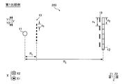
- FIG. 3 is a schematic diagram of an X-ray phase imaging apparatus 200 according to a comparative example when the magnified and projected grating pattern 9 of the first grating 3 is detected by the detector 2 as viewed from the X direction.
- the X-ray phase imaging apparatus 200 includes an X-ray source 11, a detector 12, a first grating 13, a control unit (not shown), a storage unit (not shown), And a grid moving mechanism (not shown).
- the X-ray source 11, the detector 12, and the first grating 13 shown in FIG. 3 respectively include the X-ray source 1, the detector 2, and the first grating 13 included in the X-ray phase imaging apparatus 100 shown in FIG.
- the configuration is the same as that of the one grid 3.
- the first grating 13 is arranged at a position where the distance between the X-ray source 1 and the first grating 13 is the distance R 1 .
- the detector 14 is arranged at a position where the distance between the X-ray source 11 and the detector 14 is the distance R 2 .
- the first grating 13 has an example in which the size of one period p 4 of the grating pattern 19 of the magnified and projected first grating 3 is larger than the size of the pixel size p 2 of the detector 12. Shows.
- the size of one period p 4 of the magnified and projected grating pattern 19 of the first grating 13 is larger than the pixel size p 2 of the detector 12, the magnified and projected grating of the first grating 3
- the lattice pattern 9 of the enlarged and projected first lattice 3 is detected as a striped pattern SP (see FIG. 4).
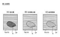
- FIG. 4A is a schematic diagram of an absorption image 15a obtained by the X-ray phase imaging apparatus 200 according to the first comparative example.
- FIG. 4B is a schematic diagram of the phase differential image 15b obtained by the X-ray phase imaging apparatus 200 according to the first comparative example.
- FIG. 4C is a schematic diagram of a dark field image 15c obtained by the X-ray phase imaging apparatus 200 according to the first comparative example.
- a striped pattern SP caused by the lattice pattern 9 of the enlarged and projected first lattice 3 is detected. Therefore, the image quality of the phase contrast image 15 is deteriorated.
- the X-ray source 1 detects the lattice pattern 9 of the first lattice 3 which is enlarged and projected by being irradiated with X-rays due to the reduction of the focus size s. If so, the relative arrangement of the first grating 3 and the X-ray source 1 is adjusted so that the magnified and projected grating pattern 9 of the first grating 3 is not detected by the detector 2. Specifically, the X-ray source 1 is resolved by the detector 2 so that the stripe pattern SP of the lattice pattern 9 of the magnified and projected first lattice 3 is not detected. And the relative arrangement of the X-ray source 1 are adjusted.
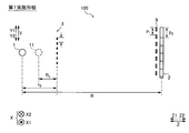
- the grating pattern 9 of the magnified and projected first grating 3 is detected by the detector 2 in the optical axis direction of the X-ray (Z direction). It is arranged apart from the first grating 3 at a position that is not detected. More care, X-rays source 1, one period p 1 of the grating pattern 9 of the first grating 3 that has been projected is enlarged, the enlargement ratio m that is smaller than the pixel size p 2 of the detector 2 Will be placed in the position. More specifically, the X-ray source 1 is arranged at a position that satisfies the following expression (4) when the following expressions (1) to (3) are defined. In FIG.
- the X-ray source 11 in the X-ray phase imaging apparatus 200 according to the first comparative example is shown by a broken line.
- m is the enlargement ratio of the lattice pattern 9 of the first lattice 3 which is enlarged and projected.
- R is the distance between the X-ray source 1 and the detector 2.
- r 0 is the distance between the X-ray source 1 and the first grating 3.
- p 1 is the period of the enlarged and projected first grating 3.
- p 0 is the period of the first grating 3.
- n is the number of pixels included in the lattice pattern 9 of the first lattice 3 which is enlarged and projected.
- p 2 is the pixel size of the detector 2.
- the above formula (4
- the X-ray source 1 and the first grating 3 are arranged at relative positions such that n in 1) approaches 1.
- the relative position is set to a position where n is 0.8 to 0.9.
- the X-ray source 1 and the first grating 3 may be arranged. That is, the X-ray source 1 and the first grating 3 may be arranged at relative positions such that the value of n satisfies the following expression (7).
- FIG. 6A is a schematic diagram of an absorption image 15a obtained by the X-ray phase imaging apparatus 100 according to the first embodiment.
- FIG. 6B is a schematic diagram of the phase differential image 15b obtained by the X-ray phase imaging apparatus 100 according to the first embodiment.
- FIG. 6C is a schematic diagram of the dark field image 15c obtained by the X-ray phase imaging apparatus 100 according to the first embodiment.
- the phase contrast images 15 shown in FIGS. 6 (A) to 6 (C) are different from the phase contrast images 15 shown in FIGS. 4 (A) to 4 (C) in the enlarged and projected first grating.
- the striped pattern SP resulting from the lattice pattern 9 of No. 3 is not detected. Therefore, by disposing the X-ray source 1 at a position that satisfies the above expression (4), it is possible to suppress deterioration of the image quality of the phase contrast image 15 even when the sharpness is increased.
- the X-ray phase imaging apparatus 100 includes the X-ray source 1 that irradiates the subject Q with X-rays, and the detector 2 that detects the X-rays emitted from the X-ray source 1.
- a first grating 3 which is disposed between the X-ray source 1 and the detector 2 and enhances coherence of X-rays emitted from the X-ray source 1, and X-rays emitted from the first lattice 3 are emitted.
- the X-ray source 1 includes a plurality of gratings including the second grating 4 and an image processing unit 5 that generates a phase contrast image 15 based on the signal detected by the detector 2, and the X-ray source 1 has a small focal point size s. Due to this, when the lattice pattern 9 of the first lattice 3 which is enlarged and projected by being irradiated with X-rays is detected, the lattice pattern 9 of the first lattice 3 which is enlarged and projected is detected. Of the first grating 3 and the X-ray source 1 so as not to be detected by the detector 2. Do arrangement is adjusted.
- the X-ray source 1 detects the striped pattern SP of the lattice pattern 9 of the first lattice 3 which is enlarged and projected by being resolved by the detector 2.
- the relative arrangement of the first grating 3 and the X-ray source 1 is adjusted so as not to occur. Accordingly, by adjusting the relative disposition of the first grating 3 and the X-ray source 1, the stripe pattern SP of the magnified and projected grating pattern 9 of the first grating 3 is resolved by the detector 2. Can be suppressed.
- the detector 2 it is possible to prevent the detector 2 from detecting the striped pattern SP of the lattice pattern 9 of the first lattice 3 that is enlarged and projected at a sharpness that cannot be recognized by the naked eye. It is possible to further suppress deterioration of the image quality of the phase contrast image 15 due to the magnified and projected grating pattern 9 of the first grating 3.
- the magnified and projected grating pattern 9 of the first grating 3 in the optical axis direction (Z direction) of the X-ray is detected by the detector 2. It is arranged apart from the first grating 3 at a position that is not detected. As a result, even when the grating pattern 9 of the first grating 3 which is enlarged and projected by irradiating X-rays is detected due to the reduction of the focus size s, the image is enlarged and projected. It is possible to reduce the enlargement ratio m of the lattice pattern 9 of the first lattice 3.
- the lattice pattern 9 of the magnified and projected first lattice 3 is not resolved, so that the lattice pattern 9 of the magnified and projected first lattice 3 is prevented from being detected by the detector 2. Therefore, it is possible to suppress the deterioration of the image quality of the image due to the detection of the lattice pattern 9 of the enlarged and projected first lattice 3.
- one period p 1 of the magnified and projected grating pattern 9 of the first grating 3 is larger than the pixel size p 2 of the detector 2. It is arranged at a position where the enlargement ratio m becomes smaller. This makes it possible to make the size of one period p 1 of the magnified and projected grating pattern 9 of the first grating 3 smaller than the pixel size p 2 of the detector 2. It is possible to further prevent the detected grating pattern 9 of the first grating 3 from being detected by the detector 2. As a result, it is possible to further suppress deterioration of the image quality of the phase contrast image 15 due to the detection of the magnified and projected grating pattern 9 of the first grating 3.
- the X-ray source 1 is arranged at a position that satisfies the above formula (4) when the above formulas (1) to (3) are defined. Accordingly, by disposing the X-ray source 1 at a position that satisfies the above equation (4), the size of one period p 1 of the magnified and projected grating pattern 9 of the first grating 3 is determined by the detector 2 It can be easily made smaller than the pixel size p 2 . As a result, it is possible to more easily suppress deterioration of the image quality of the phase contrast image 15 due to detection of the magnified and projected grating pattern 9 of the first grating 3.
- the configuration of the X-ray phase imaging apparatus 300 (see FIG. 1) according to the second embodiment will be described with reference to FIGS. 1 and 7 to 9.
- the X-ray source 1 is arranged so that the grating pattern 9 of the first grating 3 which is enlarged and projected by being irradiated with X-rays is not detected by the detector 2.
- the focus size s of is adjusted.
- the same components as those in the first embodiment are designated by the same reference numerals and the description thereof will be omitted.
- the X-ray phase imaging apparatus 300 includes an X-ray source 1, a detector 2, a first grating 3, a second grating 4, an image processing unit 5, a control unit 6, and a storage unit.
- the unit 7 and the lattice moving mechanism 8 are provided.
- the X-ray phase imaging apparatus 300 is the same as the X-ray phase imaging apparatus according to the first embodiment except that the distance r 0 between the X-ray source 1 and the first grating 3 and the focus size s of the X-ray source 1 are different.
- the configuration is the same as 100.
- the focus size s of the X-ray source 1 is adjusted so that the detector 2 does not detect the grating pattern 9 of the first grating 3 which is enlarged and projected by being irradiated with X-rays. It Specifically, the blur amount b of the magnified and projected grating pattern 9 of the first grating 3 caused by the size of the focus size s of the X-ray source 1 is the magnified and projected first The focus size s of the X-ray source 1 is set so that the grating pattern 9 of the grating 3 has a blur amount b that is not detected by the detector 2.
- the blur amount b will be described with reference to FIG. 7.
- the X-ray XR1 emitted from the Y1 direction side of the X-ray source 1 and the X-ray XR2 emitted from the Y2 direction side of the X-ray source 1 are located at the same location on the first grating 3. Even if the light is irradiated toward the detector 2, the position in the Y direction reached by the detector 2 is different. Since the positions reached by the detector 2 are different, the contour of the magnified and projected grating pattern 9 of the first grating 3 is blurred.
- the amount of blurring of the contour of the lattice pattern 9 of the first lattice 3 that is enlarged and projected is the amount of blurring b.
- the blur amount b is small, the contour of the striped pattern SP of the lattice pattern 9 of the enlarged and projected first lattice 3 becomes clear, and the striped pattern SP is clearly detected.
- the blur amount b is large, the contour of the enlarged and projected lattice pattern 9 of the first lattice 3 becomes unclear, and the striped pattern SP cannot be clearly detected. , Striped pattern SP is no longer detected.
- the blur amount b of the magnified and projected grating pattern 9 of the first grating 3 is obtained by the following equation (5).
- phase contrast image 15 When the phase contrast image 15 is acquired by imaging with high definition, it is conceivable to reduce the focus size s of the X-ray source 1.
- the blur amount b when the focal size of the X-ray source is reduced will be described below with reference to FIG.
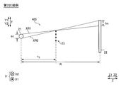
- the X-ray phase imaging apparatus 400 shown in FIG. 8 includes an X-ray source 21, a detector 22, and a first grating 33.
- the X-ray source 21 has the same configuration as the X-ray source 1 except that the focus size sc is smaller than the focus size s of the X-ray source 1 according to the first embodiment.
- the detector 22 and the first grating 33 have the same configurations as the detector 2 and the first grating 3 according to the first embodiment, respectively.
- the focus size sc of the X-ray source 21 is smaller than the focus size s of the X-ray source 1. Also in the configuration shown in FIG. 8, the relationship between the focus size sc of the X-ray source 21 and the blur amount bc is the same as that of the above equation (5). Therefore, when the focus size sc of the X-ray source 21 becomes small, the blur amount bc of the magnified and projected grating pattern 9 of the first grating 13 becomes small. When the blur amount bc of the enlarged and projected lattice pattern 9 of the first lattice 13 becomes small, the striped pattern SP (not shown) of the enlarged and projected lattice pattern 9 of the first lattice 13 becomes clear. In the phase contrast image 15, the striped pattern SP of the lattice pattern 9 of the first lattice 13 which is enlarged and projected is detected.
- the inventors of the present invention find that the blur amount b of the enlarged and projected grating pattern 9 of the first grating 3 is one period p 1 of the enlarged and projected grating pattern 9 of the first grating 3. It has been found that the grating pattern 9 of the magnified and projected first grating 3 is not detected by the detector 2 when the range is 3.0 times or more.
- the blur amount b is in a range of 3.0 times or more of one period p 1 of the lattice pattern 9 of the first lattice 3 that is enlarged and projected.
- the focus size s of the X-ray source 1 is set so that Specifically, when the X-ray source 1, one period p 1 of the grating pattern 9 of the first grating 3 that has been projected in an enlarged is larger than the pixel size p 2 of the detector 2, the formula ( The focal point size s of the X-ray source 1 is set so that the blur amount b defined by 5) satisfies the following equation (6).
- the X-ray source may be 3.0 times as long as the blur amount b is one period p 1 of the projected grating pattern 9 of the first grating 3. Even if the focus size s of 1 is adjusted, the grating pattern 9 of the first grating 3 may be detected. In such a case, the focus size s of the X-ray source 1 may be adjusted so that the blur amount b is such that the grating pattern 9 of the first grating 3 is not detected.
- the focus size of the X-ray source 1 is set so that the size of the blur amount b is 6.5 times the one period p 1 of the grating pattern 9 of the first grating 3 projected with the enlarged blur amount b. Adjust s. Further, the upper limit of the blur amount b is not particularly limited, but the lattice pattern 9 of the magnified and projected first lattice 3 is not detected in a range in which deterioration of the image quality of the obtained phase contrast image 15 is allowable. The focus size s of the X-ray source 1 may be adjusted.
- the grating pattern 9 of the magnified and projected first grating 3 is not detected by the detector 2. It was configured to do. However, for example, when the focus size s of the X-ray source 1 is set small in order to increase the sharpness, the X-ray source 1 and the first grating 3 are placed at a position that satisfies the above formula (4). 1 may not be placed in some cases. Even in that case, by setting the focus size s that satisfies the above equation (6), the phase contrast image 15 is increased in sharpness, and the phase is increased due to the lattice pattern 9 of the enlarged and projected first lattice 3. The deterioration of the image quality of the contrast image 15 can be suppressed.
- the X-ray source 1 shown in FIG. 7 is obtained from the focus size s (see FIG. 1) of the X-ray source 1 in the first embodiment and the focus size sc (see FIG. 8) of the X-ray source 21 in the second comparative example. Also shows a large focal size s. This is because the focus size s of the X-ray source 1 in the first embodiment and the focus size sc of the X-ray source 21 in the second comparative example are smaller in order to increase the sharpness. Because.
- the focal point size s of the X-ray source 1 in the second embodiment is set smaller than the focal point size of the X-ray source when performing general X-ray imaging.
- the focus size s of the X-ray source 1 in the second embodiment is set to be smaller than the focus size at the time of performing normal X-ray imaging in order to enhance the sharpness, and the blur amount b is set to the above expression ( In order to set the range to 6), it is set to be larger than the focus size s of the X-ray source 1 in the first embodiment.
- FIG. 9 shows an X-ray image 17 and an X-ray image 17 captured by changing the focus size s of the X-ray source 1 in order to obtain the range of the blur amount b of the lattice pattern 9 of the enlarged and projected first lattice 3.
- It is a Fourier transform image 18 obtained by performing a Fourier transform (FT) on the line image 17.
- the Fourier transform image 18 shows the 0th-order peak 30 and the 1st-order peak 31.
- the peak caused by the striped pattern SP of the lattice pattern 9 of the enlarged 1st grating 3 is the 1st-order peak 31.
- the presence or absence of the striped pattern SP of the lattice pattern 9 of the magnified and projected first lattice 3 in the X-ray image 17 is determined by whether or not the primary peak 31 in the Fourier transform image 18 is detected. It is judged by. That is, even when the stripe pattern SP of the lattice pattern 9 of the first lattice 3 which is enlarged and projected by the naked eye cannot be confirmed, when the primary peak 31 is set in the Fourier transform image 18, the X-ray image 17 It is considered that the striped pattern SP of the lattice pattern 9 of the first lattice 3 which is magnified and projected at is detected.
- the X-ray source 1 and the detector 2 were arranged at a position where the distance R between the X-ray source 1 and the detector 2 was 1120 mm, and an experiment was conducted.
- the X-ray source 1 and the first grating 3 are arranged at a position where the distance r 0 between the X-ray source 1 and the first grating 3 is 100 mm, and an experiment is conducted. It was Further, in the example shown in FIG. 9, an experiment was performed using the first grating 3 having a grating period p 0 of 9 ⁇ m. Further, in the example shown in FIG. 9, an experiment was conducted using the detector 2 having a pixel size p2 of 75 ⁇ m.
- the period p 1 of the magnified and projected grating pattern 9 of the first grating 3 is 100.8 ⁇ m, and n in the above formula (4) is 1.34.
- the experiment was conducted under the conditions.
- FIG. 9A is a schematic diagram of an X-ray image 17a captured with the focus size s of the X-ray source 1 set to 10 ⁇ m. Since the focal spot size s of the X-ray source 1 is set to 10 ⁇ m, the blur amount b of the magnified and projected grating pattern 9 of the first grating 3 is 102 ⁇ m. That is, in the X-ray image 17a, the blur amount b of the magnified and projected grid pattern 9 of the first grid 3 is 1. 1 of the period p 1 of the grid pattern 9 of the magnified and projected first grid 3. In this example, the focus size s of the X-ray source 1 is adjusted so as to be 01 times. In the X-ray image 17a, the striped pattern SP of the lattice pattern 9 of the first lattice 3 which was enlarged and projected was confirmed.
- the 0th-order peak 30 and the 1st-order peak 31 were confirmed. Therefore, when the focus size s of the X-ray source 1 is set to 10 ⁇ m, the striped pattern SP of the lattice pattern 9 of the first lattice 3 enlarged and projected can be confirmed in the X-ray image 17a. At the same time, in the Fourier transform image 18a, the primary peak 31 caused by the magnified and projected grating pattern 9 of the first grating 3 was confirmed.
- the blur amount b of the magnified and projected grating pattern 9 of the first grating 3 is 122 ⁇ m.
- the image 17b is a schematic diagram of the image 17b. That is, in the X-ray image 17b, the blur amount b of the magnified and projected grid pattern 9 of the first grid 3 is 1. of 1 period p 1 of the magnified and projected grid pattern 9 of the first grid 3. This is an example in which the focus size s of the X-ray source 1 is adjusted so as to be 21 times. Also in the X-ray image 17b, the striped pattern SP of the lattice pattern 9 of the first lattice 3 which was enlarged and projected was confirmed.
- the 0th-order peak 30 and the 1st-order peak 31 were confirmed. Therefore, when the focus size s of the X-ray source 1 is set to 12 ⁇ m, it is possible to confirm the striped pattern SP of the lattice pattern 9 of the first lattice 3 which is enlarged and projected in the X-ray image 17b. At the same time, in the Fourier transform image 18b, the primary peak 31 caused by the magnified and projected grating pattern 9 of the first grating 3 was confirmed.
- the blur amount b of the enlarged and projected grating pattern 9 of the first grating 3 is 143 ⁇ m.
- the image 17c it is a schematic diagram of the image 17c. That is, in the X-ray image 17c, the blur amount b of the magnified and projected grid pattern 9 of the first grid 3 is 1. 1 of the period p 1 of the grid pattern 9 of the magnified and projected first grid 3. This is an example in which the focus size s of the X-ray source 1 is adjusted so as to be 42 times. Also in the X-ray image 17c, the striped pattern SP of the lattice pattern 9 of the first lattice 3 which was enlarged and projected was confirmed.
- the 0th-order peak 30 and the 1st-order peak 31 were confirmed. Therefore, when the focus size s of the X-ray source 1 is set to 14 ⁇ m, the striped pattern SP of the lattice pattern 9 of the first lattice 3 that is enlarged and projected can be confirmed in the X-ray image 17c. At the same time, also in the Fourier transform image 18C, the primary peak 31 caused by the magnified and projected grating pattern 9 of the first grating 3 was confirmed.
- the blur amount b of the enlarged and projected grating pattern 9 of the first grating 3 is 163 ⁇ m.
- the image 17d is a schematic diagram of the image 17d. That is, in the X-ray image 17d, the blur amount b of the magnified and projected grid pattern 9 of the first grid 3 is 1. 1 of the period p 1 of the magnified and projected grid pattern 9 of the first grid 3. This is an example in which the focus size s of the X-ray source 1 is adjusted so as to be 62 times. In the X-ray image 17d, the striped pattern SP of the lattice pattern 9 of the first lattice 3 which was enlarged and projected could not be confirmed.
- the 0th order peak 30 and the 1st order peak 31 were confirmed.
- the focus size s of the X-ray source 1 was set to 16 ⁇ m, it was not possible to confirm the striped pattern SP of the lattice pattern 9 of the first lattice 3 which was enlarged and projected in the X-ray image 17d.
- the primary peak 31 resulting from the magnified and projected grating pattern 9 of the first grating 3 was confirmed.
- the blur amount b of the enlarged and projected grating pattern 9 of the first grating 3 is 306 ⁇ m.
- the blur amount b of the magnified and projected grid pattern 9 of the first grid 3 is 3.
- the 0th-order peak 30 was confirmed, but the 1st-order peak 31 was not confirmed.
- the focus size s of the X-ray source 1 is set to 30 ⁇ m, the stripe pattern SP of the lattice pattern 9 of the first lattice 3 which is enlarged and projected cannot be confirmed in the X-ray image 17e.
- the primary peak 31 due to the lattice pattern 9 of the enlarged and projected first lattice 3 could not be confirmed.
- the blur amount b of the magnified and projected grating pattern 9 of the first grating 3 increases, the striped pattern SP in the X-ray image 17 becomes unclear. became.
- the blur amount b becomes 1.6 times or more of one period p 1 of the lattice pattern 9 of the enlarged and projected first lattice 3, it cannot be visually confirmed.
- the intensity (signal intensity) of the primary peak 31 becomes smaller as the blur amount b of the lattice pattern 9 of the enlarged and projected first lattice 3 becomes larger.
- the primary peak 31 is no longer detected.
- the intensity (signal intensity) of the primary peak 31 is represented by the size of the primary peak 31 and the thickness of the illustrated line. From these results, an experimental result was obtained in which the lattice pattern 9 of the enlarged and projected first lattice 3 was not detected when the range of the blur amount b became the range shown in the above formula (6).
- the X-ray source 1 that irradiates the subject Q with X-rays
- the detector 2 that detects the X-rays emitted from the X-ray source 1, the X-ray source 1, and the detector.
- a plurality of first gratings 3 arranged between the first grating 3 and the second grating 4 for enhancing coherence of X-rays emitted from the X-ray source 1; X-ray source 1 and the image processing unit 5 that generates the phase contrast image 15 based on the signal detected by the detector 2.
- the grating pattern 9 of the first grating 3 which is enlarged and projected by irradiating the line is detected, the grating pattern 9 of the first grating 3 which is enlarged and projected is not detected by the detector 2.
- the focus size s of the X-ray source 1 is adjusted. Accordingly, similar to the X-ray phase imaging apparatus 100 according to the first embodiment, the image quality of the obtained phase contrast image 15 is increased even when the sharpness is increased by imaging by reducing the focus size s of the X-ray source 1. Can be suppressed.
- the blur amount b of the magnified and projected grating pattern 9 of the first grating 3 caused by the size of the focus size s of the X-ray source 1 is
- the focus size s of the X-ray source 1 is set such that the magnified and projected grating pattern 9 of the first grating 3 has a blur amount b that is not detected by the detector 2.
- the grid pattern 9 of the first grid 3 can be blurred.
- the blur amount b is not less than 3.0 times the one period p 1 of the lattice pattern 9 of the first lattice 3 that is enlarged and projected.
- the focus size s of the X-ray source 1 is set so as to fall within the range.
- the magnified and projected grating pattern 9 of the first grating 3 can be easily blurred until it is no longer detected by the detector 2.
- one period p 1 of the magnified and projected grating pattern 9 of the first grating 3 is larger than the pixel size p 2 of the detector 2.
- the focus size s of the X-ray source 1 is set so that the size of the blur amount b defined by the above equation (5) satisfies the above equation (6).
- the phase contrast image is caused by the lattice pattern 9 of the enlarged and projected first lattice 3. It is possible to easily suppress the deterioration of the image quality of 15.
- the example of the configuration including the first grating 3 and the second grating 4 is shown as the plurality of gratings, but the present invention is not limited to this.
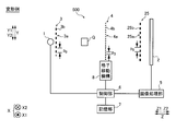
- the third grating 25 may be provided between the second grating 4 and the detector 2.
- Third grating 25 has a plurality of slits 25a and the X-ray absorbing portions 25b are arranged at a predetermined period (pitch) p 5 in the Y direction.
- Each of the slits 25a and the X-ray absorbing portion 25b is formed so as to extend linearly along the X direction.
- the slits 25a and the X-ray absorbing portion 25b are formed so as to extend parallel to each other.
- the third grating 25 is arranged between the second grating 4 and the detector 2 and is irradiated with the X-ray that has passed through the second grating 4. Further, the third lattice 25 is arranged at a position away from the second lattice 4 by the Talbot distance. The third grating 25 interferes with the self-image of the second grating 4 to form moire fringes (not shown) on the detection surface of the detector 2.
- phase contrast image 15 (absorption image 15a) is detected by detecting the moire fringes.
- a phase differential image 15b and a dark field image 15c) can be generated.
- the phase contrast image 15 (absorption image 15a, phase differential image 15b, and dark field image 15c) can be generated without depending on the pixel size p 2 of the detector 2, so that the detector 2 is selected.
- the degree of freedom of can be improved.
- the grating moving mechanism 8 may be configured to move the first grating 3 in the Y direction for imaging.
- the grating moving mechanism 8 may be configured to move the third grating 25 in the Y direction for imaging.
- the second grating 4 is the phase grating
- the present invention is not limited to this.
- the second grating 4 may be an absorption grating.
- the present invention is not limited to this.
- the present invention can be applied to a single moiré shooting method that uses moiré fringes generated by slightly rotating the second grating 4 around the X-ray optical axis direction.
Landscapes
- Health & Medical Sciences (AREA)
- General Health & Medical Sciences (AREA)
- Analytical Chemistry (AREA)
- Physics & Mathematics (AREA)
- Life Sciences & Earth Sciences (AREA)
- Chemical & Material Sciences (AREA)
- Radiology & Medical Imaging (AREA)
- Biochemistry (AREA)
- Nuclear Medicine, Radiotherapy & Molecular Imaging (AREA)
- General Physics & Mathematics (AREA)
- Immunology (AREA)
- Pathology (AREA)
- Toxicology (AREA)
- Analysing Materials By The Use Of Radiation (AREA)
- Apparatus For Radiation Diagnosis (AREA)
Abstract
このX線位相イメージング装置(100)は、X線源(1)と、検出器(2)と、第1格子(3)と第2格子(4)とを含む複数の格子と、位相コントラスト画像(15)を生成する画像処理部(5)と、を備える。そして、X線源は、拡大されて投影された第1格子の格子パターンが、検出器によって検出されないように、第1格子とX線源との相対的な配置またはX線源の焦点サイズが調整される。
Description
本発明は、X線位相イメージング装置に関し、X線の可干渉性を高める格子を備えるX線位相イメージング装置に関する。
従来、X線の可干渉性を高める格子を備えるX線位相イメージング装置が知られている。このようなX線位相イメージング装置は、たとえば、特開2012-16370号公報に開示されている。
特開2012-16370号公報のX線位相イメージング装置は、X線源と、X線源の照射方向に配置された検出器と、X線源とX線画像検出器との間において、X線源の近傍に設けられたマルチスリットと、マルチスリットと検出器との間に配置された格子とを含む複数の格子と、を備えている。マルチスリットは、X線源から照射されるX線の可干渉性を高めるために設けられている。特開2012-16370号公報のX線撮像装置は、複数の格子のいずれかを格子ピッチの方向に移動させながら、X線源から照射されたX線を複数の格子を用いて干渉させることにより、検出器において検出されるX線の強度変化を表す強度変調信号を取得する。
特開2012-16370号公報のX線撮像装置は、複数の格子の間に被写体を置かない場合の強度変調信号と、被写体を置いた場合の強度変調信号と、の位相差に基づいて、被写体内部を画像化した位相コントラスト画像を生成するように構成されている。特開2012-16370号公報に記載のような従来のX線撮像装置は、X線の吸収量ではなく、X線の位相差を利用して、被写体内を画像化することによって、X線を吸収しにくい軽元素物体や生体軟部組織を画像化することが可能である。なお、位相コントラスト画像とは、吸収像と、位相微分像と、暗視野像とを含んでいる。吸収像とは、X線が被写体を通過した際に生じるX線の減衰に基づいて画像化した像である。また、位相微分像とは、X線が被写体を通過した際に発生するX線の位相のずれをもとに画像化した像である。また、暗視野像とは、物体の小角散乱に基づくVisibilityの変化によって得られる、Visibility像のことである。また、暗視野像は、小角散乱像とも呼ばれる。「Visibility」とは、鮮明度のことである。
ここで、被写体の詳細な構造を確認するために、被写体を拡大して撮像することが望まれる場合がある。この場合、鮮明度を高めることなく被写体を拡大して撮像すると、得られる画像の画質が劣化するという不都合がある。そこで、鮮明度を高めて撮像することにより、拡大した画像を撮像する場合でも、画質の低下を抑制することができる。鮮明度を高めるためには、X線源の焦点サイズを小さくすることが考えられる。しかしながら、特開2012-16370号公報では、X線源の可干渉性を高めるために、X線源にマルチスリットが設けられている。X線源にマルチスリットが備えられた構成においてX線源の焦点サイズを小さくすると、マルチスリットの格子パターンが解像され、画像上に縞模様として検出される。そのため、マルチスリットの格子パターンの縞模様によって、得られる画像の画質が劣化するという問題点がある。
この発明は、上記のような課題を解決するためになされたものであり、X線源の焦点サイズを小さくすることにより鮮明度を高めて撮像する場合でも、得られる画像の画質が劣化することを抑制することが可能なX線位相イメージング装置を提供することである。
上記目的を達成するために、この発明の一の局面におけるX線位相イメージング装置は、被写体にX線を照射するX線源と、X線源から照射されたX線を検出する検出器と、X線源と検出器との間に配置され、X線源から照射されるX線の可干渉性を高める第1格子と、第1格子からのX線が照射される第2格子とを含む複数の格子と、検出器によって検出された信号に基づいて位相コントラスト画像を生成する画像処理部と、を備え、X線源は、焦点サイズを小さくすることに起因して、X線が照射されることにより拡大されて投影された第1格子の格子パターンが検出される場合に、拡大されて投影された第1格子の格子パターンが、検出器によって検出されないように、第1格子とX線源との相対的な配置またはX線源の焦点サイズが調整される。
この発明の一の局面におけるX線位相イメージング装置では、上記のように、X線源は、焦点サイズを小さくすることに起因して、X線が照射されることにより拡大されて投影された第1格子の格子パターンが検出される場合に、拡大されて投影された第1格子の格子パターンが、検出器によって検出されないように、第1格子とX線源との相対的な配置またはX線源の焦点サイズが調整される。これにより、X線源の焦点サイズを小さくすることにより鮮明度を高めて撮像した場合でも、拡大されて投影された第1格子の格子パターンが検出器によって検出されることを抑制することができる。その結果、X線源の焦点サイズを小さくすることにより鮮明度を高めて撮像する場合でも、得られる画像の画質が劣化することを抑制することができる。
上記一の局面におけるX線位相イメージング装置において、好ましくは、X線源は、検出器によって解像されることにより、拡大されて投影された第1格子の格子パターンの縞模様が検出されないように、第1格子とX線源との相対的な配置またはX線源の焦点サイズが調整される。このように構成すれば、第1格子とX線源との相対的な配置またはX線源の焦点サイズを調整することにより、拡大されて投影された第1格子の格子パターンの縞模様が検出器によって解像されることを抑制することができる。その結果、たとえば、肉眼で認識できない鮮明度において、拡大されて投影された第1格子の格子パターンの縞模様が検出器によって検出されることを抑制することが可能となるので、拡大されて投影された第1格子の格子パターンに起因して画像の画質が劣化することを、より抑制することができる。
上記一の局面におけるX線位相イメージング装置において、好ましくは、X線源は、X線の光軸方向において、拡大されて投影された第1格子の格子パターンが検出器によって検出されない位置に、第1格子から離間して配置される。このように構成すれば、焦点サイズを小さくすることに起因して、X線が照射されることにより拡大されて投影された第1格子の格子パターンが検出される場合でも、拡大されて投影された第1格子の格子パターンの拡大率を小さくすることができる。その結果、拡大されて投影された第1格子の格子パターンが解像されなくなるため、拡大されて投影された第1格子の格子パターンが検出器によって検出されることを抑制することが可能となり、拡大されて投影された第1格子の格子パターンが検出されることに起因して画像の画質が劣化することを抑制することができる。
上記一の局面におけるX線位相イメージング装置において、好ましくは、X線源は、拡大されて投影された第1格子の格子パターンの1周期が、検出器の画素サイズよりも小さくなるような拡大率となる位置に配置される。このように構成すれば、拡大されて投影された第1格子の格子パターンの1周期の大きさを、検出器の画素サイズよりも小さくすることが可能となるので、拡大されて投影された第1格子の格子パターンが検出器によって検出されることをより抑制することができる。その結果、拡大されて投影された第1格子の格子パターンが検出されることに起因して画像の画質が劣化することをより抑制することができる。
この場合、好ましくは、X線源は、以下の式(1)~(3)を定義した場合、以下の式(4)を満たすような位置に配置される。

ここで、mは、拡大されて投影された第1格子の格子パターンの拡大率である。また、Rは、X線源と検出器との間の距離である。また、r0は、X線源と第1格子との間の距離である。また、p1は、拡大されて投影された第1格子の格子パターンの周期である。また、p0は、第1格子の格子周期である。また、nは、拡大されて投影された第1格子の格子パターンに含まれる画素数である。また、p2は、検出器の画素サイズである。
このように構成すれば、上記式(4)を満たす位置にX線源を配置することにより、拡大されて投影された第1格子の格子パターンの1周期の大きさを、検出器の画素サイズよりも容易に小さくすることができる。その結果、拡大されて投影された第1格子の格子パターンが検出されることに起因して画像の画質が劣化することを、より容易に抑制することができる。
このように構成すれば、上記式(4)を満たす位置にX線源を配置することにより、拡大されて投影された第1格子の格子パターンの1周期の大きさを、検出器の画素サイズよりも容易に小さくすることができる。その結果、拡大されて投影された第1格子の格子パターンが検出されることに起因して画像の画質が劣化することを、より容易に抑制することができる。
上記一の局面におけるX線位相イメージング装置において、好ましくは、X線源の焦点サイズの大きさに起因して生じる、拡大されて投影された第1格子の格子パターンのぼけ量が、拡大されて投影された第1格子の格子パターンが検出器によって検出されなくなるぼけ量となるように、X線源の焦点サイズが設定される。このように構成すれば、焦点サイズを小さくすることに起因して、X線が照射されることにより拡大されて投影された第1格子の格子パターンが検出される場合でも、拡大されて投影された第1格子の格子パターンをぼけさせることができる。その結果、拡大されて投影された第1格子の格子パターンを検出器で検出できなくなるまでぼけさせることが可能となるので、拡大されて投影された第1格子の格子パターンに起因して、画像の画質が劣化することを抑制することができる。
ここで、本願発明者らが鋭意検討した結果、ぼけ量が、拡大されて投影された第1格子の格子パターンの1周期の3.0倍以上となった場合に、拡大されて投影された第1格子の格子パターンが検出器によって検出されないという知見を得た。この知見に基づいて、拡大されて投影された第1格子の格子パターンが検出器によって検出されなくなるぼけ量となるように、X線源の焦点サイズが設定される場合、好ましくは、X線源は、ぼけ量が、拡大されて投影された第1格子の格子パターンの1周期の3.0倍以上、の範囲となるように、X線源の焦点サイズが設定される。このように構成すれば、拡大されて投影された第1格子の格子パターンを、検出器によって検出されなくなるまで容易にぼけさせることができる。その結果、拡大されて投影された第1格子の格子パターンに起因して、画像の画質が劣化することを容易に抑制することができる。
上記拡大されて投影された第1格子の格子パターンが検出器によって検出されなくなるぼけ量となるように、X線源の焦点サイズが設定される構成において、好ましくは、X線源は、拡大されて投影された第1格子の格子パターンの1周期が、検出器の画素サイズよりも大きくなる場合に、以下の式(5)により定義されるぼけ量の大きさが、以下の式(6)を満たすように、X線源の焦点サイズが設定される。

ここで、bは、上記ぼけ量である。また、sは、X線源の焦点サイズである。
このように構成すれば、拡大されて投影された第1格子の格子パターンの1周期の大きさを、検出器の画素サイズよりも小さくすることが困難な場合でも、拡大されて投影された第1格子の格子パターンが検出器によって検出されることを容易に抑制することができる。その結果、X線源の焦点サイズsを、上記式(6)を満たす焦点サイズに調整することにより、拡大されて投影された第1格子の格子パターンに起因して画像の画質が劣化することを容易に抑制することができる。
このように構成すれば、拡大されて投影された第1格子の格子パターンの1周期の大きさを、検出器の画素サイズよりも小さくすることが困難な場合でも、拡大されて投影された第1格子の格子パターンが検出器によって検出されることを容易に抑制することができる。その結果、X線源の焦点サイズsを、上記式(6)を満たす焦点サイズに調整することにより、拡大されて投影された第1格子の格子パターンに起因して画像の画質が劣化することを容易に抑制することができる。
上記一の局面におけるX線位相イメージング装置において、好ましくは、第2格子と、検出器との間に配置された第3格子をさらに含む。このように構成すれば、検出器の画素サイズの大きさが、第2格子の自己像の1周期の大きさよりも大きい場合でも、モアレ縞を検出することにより、位相コントラスト画像を生成することができる。その結果、検出器の画素サイズに依存することなく位相コントラスト画像を生成することが可能となるので、検出器の選択の自由度を向上させることができる。
本発明によれば、上記のように、X線源の焦点サイズを小さくすることにより鮮明度を高めて撮像する場合でも、得られる画像の画質が劣化することを抑制することが可能なX線位相イメージング装置を提供することができる。
以下、本発明を具体化した実施形態を図面に基づいて説明する。
[第1実施形態]
図1~図6を参照して、第1実施形態によるX線位相イメージング装置100の構成について説明する。
図1~図6を参照して、第1実施形態によるX線位相イメージング装置100の構成について説明する。
(X線位相イメージング装置の構成)
まず、図1を参照して、本発明の本実施形態によるX線位相イメージング装置100の構成について説明する。
まず、図1を参照して、本発明の本実施形態によるX線位相イメージング装置100の構成について説明する。
図1に示すように、X線位相イメージング装置100は、タルボ(Talbot)効果を利用して、被写体Qの内部を画像化する装置である。X線位相イメージング装置100は、複数の格子のうち、いずれか1つを、格子の周期方向(Y方向)に並進移動させながら被写体Qを撮像するように構成されている。
図1に示すように、X線位相イメージング装置100は、X線源1と、検出器2と、第1格子3と第2格子4とを含む複数の格子と、画像処理部5と、制御部6と、記憶部7と、格子移動機構8と、を備えている。なお、本明細書において、X線源1から第1格子3に向かう方向をZ2方向、その逆向きの方向をZ1方向とする。また、Z方向と直交する紙面内の左右方向をX方向とし、図1の紙面の奥に向かう方向をX2方向、図1の紙面の手前側に向かう方向をX1方向とする。また、Z方向と直交する面内の上下方向をY方向とし、上方向をY1方向、下方向をY2方向とする。
X線源1は、高電圧が印加されることにより、X線を発生させるとともに、発生されたX線を被写体Qに向けて照射するように構成されている。なお、X線源1は、焦点サイズsが調整されることにより、得られる画像の鮮明度が調整される。焦点サイズsを小さくした場合、得られる画像の鮮明度を高めることができる。
第1格子3は、Y方向に所定の周期(ピッチ)p0で配列される複数のスリット3aおよび、X線吸収部3bを有している。各スリット3aおよびX線吸収部3bはそれぞれ、X方向に沿って直線状に延びるように形成されている。また、各スリット3aおよびX線吸収部3bはそれぞれ、互いに平行に延びるように形成されている。第1格子3は、いわゆる吸収格子である。第1格子3には、X線源1からX線が照射される。第1格子3は、各スリット3aを通過したX線を、各スリット3aの位置に対応する線光源とするように構成されている。
第2格子4は、第1格子3と、検出器2との間に配置されており、第1格子3を通過したX線が照射される。第2格子4は、タルボ効果により、第2格子4の自己像(図示せず)を形成するために設けられている。可干渉性を有するX線が、スリットが形成された格子を通過すると、格子から所定の距離(タルボ距離)離れた位置に、格子の像(自己像)が形成される。これをタルボ効果という。
第2格子4は、Y方向に所定の周期(ピッチ)p3で配列される複数のスリット4aおよび、X線位相変化部4bを有している。各スリット4aおよびX線位相変化部4bはそれぞれ、X方向に沿って直線状に延びるように形成されている。また、各スリット4aおよびX線位相変化部4bはそれぞれ、互いに平行に延びるように形成されている。第2格子4は、いわゆる位相格子である。第1格子3、第2格子4はそれぞれ異なる役割を持つ格子であるが、スリット3aおよびスリット4aはそれぞれX線を透過させる。また、X線吸収部3bはX線を遮蔽する役割を担っており、X線位相変化部4bはスリット4aとの屈折率の違いによってX線の位相を変化させる。
検出器2は、X線を検出するとともに、検出されたX線を電気信号に変換し、変換された電気信号を画像信号として読み取るように構成されている。検出器2は、たとえば、FPD(Flat Panel Detector)である。検出器2は、複数の変換素子(図示せず)と複数の変換素子上に配置された画素電極(図示せず)とにより構成されている。複数の変換素子および画素電極は、所定の周期(画素サイズp2)で、X方向およびY方向にアレイ状に配列されている。また、検出器2は、取得した画像信号を、画像処理部5に出力するように構成されている。
画像処理部5は、検出器2から出力された画像信号に基づいて、位相コントラスト画像15(図4参照)を生成するように構成されている。第1実施形態では、画像処理部5は、たとえば、位相コントラスト画像15として、吸収像15a(図4参照)、位相微分像15b(図4参照)および暗視野像15c(図4参照)を生成する。画像処理部5は、たとえば、GPU(Graphics Processing Unit)または画像処理用に構成されたFPGA(Field-Programmable Gate Array)などのプロセッサを含む。
制御部6は、格子移動機構8を制御して、第2格子4を移動させるように構成されている。制御部6は、たとえば、CPU(Central Processing Unit)、ROM(Read Only Memory)およびRAM(Random Access Memory)などを含む。
記憶部7は、画像処理部5が生成した位相コントラスト画像15などを保存するように構成されている。記憶部7は、たとえば、HDD(Hard Disk Drive)や不揮発性のメモリなどを含む。
格子移動機構8は、制御部6の制御の下、第2格子4を移動可能に構成されている。また、格子移動機構8は、第2格子4を保持している。
(格子移動機構)
図2に示すように、格子移動機構8は、X方向、Y方向、Z方向、Z方向の軸線周りの回転方向Rz、X方向の軸線周りの回転方向Rx、および、Y方向の軸線周りの回転方向Ryに第1格子3を移動可能に構成されている。具体的には、格子移動機構8は、X方向直動機構80と、Y方向直動機構81と、Z方向直動機構82と、直動機構接続部83と、ステージ支持部駆動部84と、ステージ支持部85と、ステージ駆動部86と、ステージ87とを含む。X方向直動機構80は、X方向に移動可能に構成されている。X方向直動機構80は、たとえば、モータなどを含む。Y方向直動機構81は、Y方向に移動可能に構成されている。Y方向直動機構81は、たとえば、モータなどを含む。Z方向直動機構82は、Z方向に移動可能に構成されている。Z方向直動機構82は、たとえば、モータなどを含む。
図2に示すように、格子移動機構8は、X方向、Y方向、Z方向、Z方向の軸線周りの回転方向Rz、X方向の軸線周りの回転方向Rx、および、Y方向の軸線周りの回転方向Ryに第1格子3を移動可能に構成されている。具体的には、格子移動機構8は、X方向直動機構80と、Y方向直動機構81と、Z方向直動機構82と、直動機構接続部83と、ステージ支持部駆動部84と、ステージ支持部85と、ステージ駆動部86と、ステージ87とを含む。X方向直動機構80は、X方向に移動可能に構成されている。X方向直動機構80は、たとえば、モータなどを含む。Y方向直動機構81は、Y方向に移動可能に構成されている。Y方向直動機構81は、たとえば、モータなどを含む。Z方向直動機構82は、Z方向に移動可能に構成されている。Z方向直動機構82は、たとえば、モータなどを含む。
格子移動機構8は、X方向直動機構80の動作により、第1格子3をX方向に移動させるように構成されている。また、格子移動機構8は、Y方向直動機構81の動作により、第1格子3をY方向に移動させるように構成されている。また、格子移動機構8は、Z方向直動機構82の動作により、第1格子3をZ方向に移動させるように構成されている。
ステージ支持部85は、ステージ87を下方(Y1方向)から支持している。ステージ駆動部86は、ステージ87をX方向に往復移動させるように構成されている。ステージ87は、底部がステージ支持部85に向けて凸曲面状に形成されており、X方向に往復移動されることにより、Z方向の軸線周り(Rz方向)に回動するように構成されている。また、ステージ支持部駆動部84は、ステージ支持部85をZ方向に往復移動させるように構成されている。また、ステージ支持部85は底部が直動機構接続部83に向けて凸曲面状に形成されており、Z方向に往復移動されることにより、X方向の軸線周り(Rx方向)に回動するように構成されている。また、直動機構接続部83は、Y方向の軸線周り(Ry方向)に回動可能にX方向直動機構80に設けられている。したがって、格子移動機構8は、格子をY方向の中心軸線周りに回動させることができる。
ここで、被写体Qを拡大して撮像する場合、鮮明度を高めることなく拡大して撮像すると、得られる位相コントラスト画像15が不鮮明となる場合がある。そこで、得られる位相コントラスト画像15の鮮明度を高めることが考えられる。X線源1の焦点サイズsを小さくすることにより、得られる位相コントラスト画像15の鮮明度を高めることができる。しかしながら、X線源1の焦点サイズsを小さくした場合、第1格子3が解像されることにより、検出器2において、第1格子3の格子パターン9(図1参照)が拡大されて投影される。拡大されて投影された第1格子3の格子パターン9の周期p1(図1参照)の大きさによっては、拡大されて投影された第1格子3の格子パターン9が検出器2によって検出される場合がある。以下、図3を参照して、拡大されて投影された第1格子3の格子パターン9が検出器2によって検出される場合について説明する。
(第1比較例)
図3は、拡大されて投影された第1格子3の格子パターン9が検出器2によって検出される場合の比較例によるX線位相イメージング装置200をX方向から見た模式図である。図3に示すように、X線位相イメージング装置200は、X線源11と、検出器12と、第1格子13と、制御部(図示せず)と、記憶部(図示せず)と、格子移動機構(図示せず)とを備える。なお、図3に示すX線源11と、検出器12と、第1格子13とは、それぞれ、図1に示すX線位相イメージング装置100が備えるX線源1と、検出器2と、第1格子3と、同様の構成である。
図3は、拡大されて投影された第1格子3の格子パターン9が検出器2によって検出される場合の比較例によるX線位相イメージング装置200をX方向から見た模式図である。図3に示すように、X線位相イメージング装置200は、X線源11と、検出器12と、第1格子13と、制御部(図示せず)と、記憶部(図示せず)と、格子移動機構(図示せず)とを備える。なお、図3に示すX線源11と、検出器12と、第1格子13とは、それぞれ、図1に示すX線位相イメージング装置100が備えるX線源1と、検出器2と、第1格子3と、同様の構成である。
図3に示す例は、X線源1と、第1格子13との間の距離が、距離R1となる位置に第1格子13を配置している。また、図3に示す例は、X線源11と検出器14との間の距離が、距離R2となる位置に検出器14を配置している。
図3では、第1格子13は、拡大されて投影された第1格子3の格子パターン19の1周期p4の大きさが、検出器12の画素サイズp2の大きさよりも大きくなる例を示している。拡大されて投影された第1格子13の格子パターン19の1周期p4の大きさが、検出器12の画素サイズp2よりも大きくなる場合、拡大されて投影された第1格子3の格子パターン19が解像され、生成される位相コントラスト画像15において、拡大されて投影された第1格子3の格子パターン9が縞模様SP(図4参照)として検出される。
図4(A)は、第1比較例によるX線位相イメージング装置200によって得られる吸収像15aの模式図である。図4(B)は、第1比較例によるX線位相イメージング装置200によって得られる位相微分像15bの模式図である。図4(C)は、第1比較例によるX線位相イメージング装置200によって得られる暗視野像15cの模式図である。図4(A)~図4(C)に示す各位相コントラスト画像15において、拡大されて投影された第1格子3の格子パターン9に起因する縞模様SPが検出される。そのため、位相コントラスト画像15の画質が劣化している。
そこで、第1実施形態では、X線源1は、焦点サイズsを小さくすることに起因して、X線が照射されることにより拡大されて投影された第1格子3の格子パターン9が検出される場合に、拡大されて投影された第1格子3の格子パターン9が、検出器2によって検出されないように、第1格子3とX線源1との相対的な配置が調整される。具体的には、X線源1は、検出器2によって解像されることにより、拡大されて投影された第1格子3の格子パターン9の縞模様SPが検出されないように、第1格子3とX線源1との相対的な配置が調整される。
図5に示すように、第1実施形態では、X線源1は、X線の光軸方向(Z方向)において、拡大されて投影された第1格子3の格子パターン9が検出器2によって検出されない位置に、第1格子3から離間して配置される。具体気には、X線源1は、拡大されて投影された第1格子3の格子パターン9の1周期p1が、検出器2の画素サイズp2よりも小さくなるような拡大率mとなる位置に配置される。より具体的には、X線源1は、以下の式(1)~(3)を定義した場合、以下の式(4)を満たすような位置に配置される。なお、図5には、比較のために、第1比較例によるX線位相イメージング装置200におけるX線源11を破線で図示している。

なお、mは、拡大されて投影された第1格子3の格子パターン9の拡大率である。また、Rは、X線源1と検出器2との間の距離である。また、r0は、X線源1と第1格子3との間の距離である。また、p1は、拡大されて投影された第1格子3の周期である。また、p0は、第1格子3の周期である。また、nは、拡大されて投影された第1格子3の格子パターン9に含まれる画素数である。また、p2は、検出器2の画素サイズである。
図5に示すように、上記式(4)を満たす位置にX線源1を配置した場合、拡大されて投影された第1格子3の格子パターン9の1周期p1が、検出器2の画素サイズp2よりも小さくなる。そのため、検出器2によって拡大されて投影された第1格子3の格子パターン9が検出されなくなる。なお、X線源1と第1格子3との間の距離r0を遠ざけると、検出器2に到達するX線の線量が低下する。そのため、X線の線量不足に起因する位相コントラスト画像15の画質の劣化を抑制するために、撮像時間を長くしなければならない。しかしながら、撮像時間を長くすると、被ばく量が増加するため、好ましくない。
そこで、第1実施形態では、拡大されて投影された第1格子3の格子パターン9に起因する位相コントラスト画像15の画質の劣化を抑制しつつ、被ばく量を増加させないために、上記式(4)におけるnが1に近づくような相対位置にX線源1と第1格子3とを配置する。好ましくは、n=1となる相対位置にX線源1と第1格子3とを配置する。また、拡大されて投影された第1格子3の格子パターン9に起因する位相コントラスト画像15の画質の劣化をより抑制したい場合には、nが0.8~0.9となる位置に相対位置にX線源1と第1格子3とを配置してもよい。すなわち、nの値が、以下の式(7)を満たすような相対位置に、相対位置にX線源1と第1格子3とを配置すればよい。

図6(A)は、第1実施形態によるX線位相イメージング装置100によって得られる吸収像15aの模式図である。図6(B)は、第1実施形態によるX線位相イメージング装置100によって得られる位相微分像15bの模式図である。図6(C)は、第1実施形態によるX線位相イメージング装置100によって得られる暗視野像15cの模式図である。図6(A)~図6(C)に示す各位相コントラスト画像15では、図4(A)~図4(C)に示す各位相コントラスト画像15と異なり、拡大されて投影された第1格子3の格子パターン9に起因する縞模様SPが検出されていない。したがって、上記式(4)を満たす位置にX線源1を配置することにより、鮮明度を高めた場合でも、位相コントラスト画像15の画質が劣化することを抑制することができる。
(第1実施形態の効果)
第1実施形態では、以下のような効果を得ることができる。
第1実施形態では、以下のような効果を得ることができる。
第1実施形態では、上記のように、X線位相イメージング装置100は、被写体QにX線を照射するX線源1と、X線源1から照射されたX線を検出する検出器2と、X線源1と検出器2との間に配置され、X線源1から照射されるX線の可干渉性を高める第1格子3と、第1格子3からのX線が照射される第2格子4とを含む複数の格子と、検出器2によって検出された信号に基づいて位相コントラスト画像15を生成する画像処理部5と、を備え、X線源1は、焦点サイズsを小さくすることに起因して、X線が照射されることにより拡大されて投影された第1格子3の格子パターン9が検出される場合に、拡大されて投影された第1格子3の格子パターン9が、検出器2によって検出されないように、第1格子3とX線源1との相対的な配置が調整される。これにより、X線源1の焦点サイズsを小さくすることにより鮮明度を高めて撮像した場合でも、拡大されて投影された第1格子3の格子パターン9が検出器2によって検出されることを抑制することができる。その結果、X線源1の焦点サイズsを小さくすることにより鮮明度を高めて撮像する場合でも、得られる位相コントラスト画像15の画質が劣化することを抑制することができる。
また、第1実施形態では、上記のように、X線源1は、検出器2によって解像されることにより、拡大されて投影された第1格子3の格子パターン9の縞模様SPが検出されないように、第1格子3とX線源1との相対的な配置が調整される。これにより、第1格子3とX線源1との相対的な配置を調整することにより、拡大されて投影された第1格子3の格子パターン9の縞模様SPが検出器2によって解像されることを抑制することができる。その結果、たとえば、肉眼で認識できない鮮明度において、拡大されて投影された第1格子3の格子パターン9の縞模様SPが検出器2によって検出されることを抑制することが可能となるので、拡大されて投影された第1格子3の格子パターン9に起因して位相コントラスト画像15の画質が劣化することを、より抑制することができる。
また、第1実施形態では、上記のように、X線源1は、X線の光軸方向(Z方向)において、拡大されて投影された第1格子3の格子パターン9が検出器2によって検出されない位置に、第1格子3から離間して配置される。これにより、焦点サイズsを小さくすることに起因して、X線が照射されることにより拡大されて投影された第1格子3の格子パターン9が検出される場合でも、拡大されて投影された第1格子3の格子パターン9の拡大率mを小さくすることができる。その結果、拡大されて投影された第1格子3の格子パターン9が解像されなくなるため、拡大されて投影された第1格子3の格子パターン9が検出器2によって検出されることを抑制することが可能となり、拡大されて投影された第1格子3の格子パターン9が検出されることに起因して画像の画質が劣化することを抑制することができる。
また、第1実施形態では、上記のように、X線源1は、拡大されて投影された第1格子3の格子パターン9の1周期p1が、検出器2の画素サイズp2よりも小さくなるような拡大率mとなる位置に配置される。これにより、拡大されて投影された第1格子3の格子パターン9の1周期p1の大きさを、検出器2の画素サイズp2よりも小さくすることが可能となるので、拡大されて投影された第1格子3の格子パターン9が検出器2によって検出されることをより抑制することができる。その結果、拡大されて投影された第1格子3の格子パターン9が検出されることに起因して位相コントラスト画像15の画質が劣化することをより抑制することができる。
また、第1実施形態では、上記のように、X線源1は、上記式(1)~(3)を定義した場合、上記式(4)を満たすような位置に配置される。これにより、上記式(4)を満たす位置にX線源1を配置することにより、拡大されて投影された第1格子3の格子パターン9の1周期p1の大きさを、検出器2の画素サイズp2よりも容易に小さくすることができる。その結果、拡大されて投影された第1格子3の格子パターン9が検出されることに起因して位相コントラスト画像15の画質が劣化することを、より容易に抑制することができる。
[第2実施形態]
次に、図1および図7~図9を参照して、第2実施形態によるX線位相イメージング装置300(図1参照)の構成について説明する。拡大されて投影された第1格子3の格子パターン9が検出器2において検出されなくなるようにX線源1と第1格子3との間の距離r0を調整する第1実施形態と異なり、第2実施形態によるX線位相イメージング装置300では、X線が照射されることにより拡大されて投影された第1格子3の格子パターン9が、検出器2によって検出されないように、X線源1の焦点サイズsが調整される。なお、上記第1実施形態と同様の構成については同様の符号を付し、説明を省略する。
次に、図1および図7~図9を参照して、第2実施形態によるX線位相イメージング装置300(図1参照)の構成について説明する。拡大されて投影された第1格子3の格子パターン9が検出器2において検出されなくなるようにX線源1と第1格子3との間の距離r0を調整する第1実施形態と異なり、第2実施形態によるX線位相イメージング装置300では、X線が照射されることにより拡大されて投影された第1格子3の格子パターン9が、検出器2によって検出されないように、X線源1の焦点サイズsが調整される。なお、上記第1実施形態と同様の構成については同様の符号を付し、説明を省略する。
図1に示すように、X線位相イメージング装置300は、X線源1と、検出器2と、第1格子3と、第2格子4と、画像処理部5と、制御部6と、記憶部7と、格子移動機構8とを備える。X線位相イメージング装置300は、X線源1と第1格子3との間の距離r0およびX線源1の焦点サイズsが異なる点を除いて、第1実施形態によるX線位相イメージング装置100と同様の構成である。
第2実施形態では、X線が照射されることにより拡大されて投影された第1格子3の格子パターン9が、検出器2によって検出されないように、X線源1の焦点サイズsが調整される。具体的には、X線源1の焦点サイズsの大きさに起因して生じる、拡大されて投影された第1格子3の格子パターン9のぼけ量bが、拡大されて投影された第1格子3の格子パターン9が検出器2によって検出されなくなるぼけ量bとなるように、X線源1の焦点サイズsが設定される。
ここで、図7を参照して、ぼけ量bについて説明する。図7に示すように、X線源1のY1方向側から照射されるX線XR1と、X線源1のY2方向側から照射されるX線XR2とでは、第1格子3の同一箇所に向けて照射された場合でも、検出器2において到達するY方向の位置が異なる。検出器2において到達する位置が異なるため、拡大されて投影された第1格子3の格子パターン9の輪郭がぼける。拡大されて投影された第1格子3の格子パターン9の輪郭がぼける量が、ぼけ量bである。ぼけ量bが小さい場合、拡大されて投影された第1格子3の格子パターン9の縞模様SPの輪郭が鮮明となり、縞模様SPが鮮明に検出される。一方、ぼけ量bが大きい場合、拡大されて投影された第1格子3の格子パターン9の輪郭が不鮮明となり、縞模様SPが鮮明に検出されなくなり、ぼけ量bが所定の大きさ以上になると、縞模様SPとして検出されなくなる。
拡大されて投影された第1格子3の格子パターン9のぼけ量bは、以下に示す式(5)により取得される。

鮮明度を高めて撮像することにより、位相コントラスト画像15を取得する場合、X線源1の焦点サイズsを小さくすることが考えらえる。以下、図8を参照して、X線源の焦点サイズを小さくした場合のぼけ量bについて説明する。
(第2比較例)
図8に示すX線位相イメージング装置400は、X線源21と、検出器22と、第1格子33と、を備えている。X線源21は、焦点サイズscが、上記第1実施形態によるX線源1の焦点サイズsよりも小さい点を除いて、X線源1と同様の構成である。また、検出器22、および第1格子33は、それぞれ、上記第1実施形態による検出器2および第1格子3と同様の構成である。
図8に示すX線位相イメージング装置400は、X線源21と、検出器22と、第1格子33と、を備えている。X線源21は、焦点サイズscが、上記第1実施形態によるX線源1の焦点サイズsよりも小さい点を除いて、X線源1と同様の構成である。また、検出器22、および第1格子33は、それぞれ、上記第1実施形態による検出器2および第1格子3と同様の構成である。
図8に示す例では、X線源21の焦点サイズscが、X線源1の焦点サイズsよりも小さい場合を示している。図8に示す構成においても、X線源21の焦点サイズscとぼけ量bcとの関係は、上記式(5)と同様である。したがって、X線源21の焦点サイズscが小さくなると、拡大されて投影された第1格子13の格子パターン9のぼけ量bcが小さくなる。拡大されて投影された第1格子13の格子パターン9のぼけ量bcが小さくなると、拡大されて投影された第1格子13の格子パターン9の縞模様SP(図示せず)が鮮明となるため、位相コントラスト画像15において、拡大されて投影された第1格子13の格子パターン9の縞模様SPが検出される。
ここで、本発明の発明者らは、拡大されて投影された第1格子3の格子パターン9のぼけ量bが、拡大されて投影された第1格子3の格子パターン9の1周期p1の3.0倍以上の範囲となる場合に、拡大されて投影された第1格子3の格子パターン9が検出器2によって検出されなくなるという知見を得た。
上記知見に基づいて、第2実施形態では、X線源1は、ぼけ量bが、拡大されて投影された第1格子3の格子パターン9の1周期p1の3.0倍以上の範囲となるように、X線源1の焦点サイズsが設定される。具体的には、X線源1は、拡大されて投影された第1格子3の格子パターン9の1周期p1が、検出器2の画素サイズp2よりも大きくなる場合に、上記式(5)により定義されるぼけ量bの大きさが、以下の式(6)を満たすように、X線源1の焦点サイズsが設定される。

なお、X線源1および複数の格子の配置によっては、ぼけ量bが拡大されて投影された第1格子3の格子パターン9の1周期p1の3.0倍となるようにX線源1の焦点サイズsを調整したとしても、第1格子3の格子パターン9が検出される場合がある。そのような場合は、第1格子3の格子パターン9が検出されないようなぼけ量bの大きさとなるように、X線源1の焦点サイズsを調整すればよい。たとえば、ぼけ量bの大きさが、ぼけ量bが拡大されて投影された第1格子3の格子パターン9の1周期p1の6.5倍となるように、X線源1の焦点サイズsを調整すればよい。また、ぼけ量bの上限については、特に制限はないが、得られる位相コントラスト画像15の画質の劣化が許容できる範囲において、拡大されて投影された第1格子3の格子パターン9が検出されないようにX線源1の焦点サイズsを調整すればよい。
第1実施形態では、X線源1と第1格子3との間の距離r0を大きくすることにより、拡大されて投影された第1格子3の格子パターン9を検出器2において検出されなくする構成であった。しかしながら、たとえば、鮮明度を高めるために、X線源1の焦点サイズsを小さく設定する際に、X線源1と第1格子3とを、上記式(4)を満たす位置にX線源1を配置できない場合がある。その場合でも、上記式(6)を満たす焦点サイズsに設定することにより、位相コントラスト画像15の鮮明度を高めつつ、拡大されて投影された第1格子3の格子パターン9に起因して位相コントラスト画像15の画質の劣化を抑制することができる。
なお、図7に示すX線源1は、第1実施形態におけるX線源1の焦点サイズs(図1参照)および第2比較例におけるX線源21の焦点サイズsc(図8参照)よりも焦点サイズsを大きく図示している。これは、第1実施形態におけるX線源1の焦点サイズsおよび第2比較例におけるX線源21の焦点サイズscが、鮮明度を高めるために焦点サイズsおよび焦点サイズscを小さくしているからである。なお、第2実施形態におけるX線源1の焦点サイズsは、一般的なX線撮像を行う際のX線源の焦点サイズよりも小さく設定される。すなわち、第2実施形態におけるX線源1の焦点サイズsは、鮮明度を高めるために、通常のX線撮影を行う際の焦点サイズよりも小さく設定され、かつ、ぼけ量bを上記式(6)の範囲とするために、上記第1実施形態におけるX線源1の焦点サイズsよりも大きく設定される。
(実験例)
次に、図9を参照して、上記知見を得た実験について説明する。
次に、図9を参照して、上記知見を得た実験について説明する。
図9は、拡大されて投影された第1格子3の格子パターン9のぼけ量bの範囲を取得するために、X線源1の焦点サイズsを変更して撮像したX線画像17およびX線画像17をフーリエ変換(FT)することにより得られたフーリエ変換画像18である。なお、フーリエ変換画像18には、0次ピーク30と、1次ピーク31とが写っている。フーリエ変換画像18における0次ピーク30と1次ピーク31とのうち、拡大されて投影された第1格子3の格子パターン9の縞模様SPに起因するピークが1次ピーク31である。
図9に示す実験例では、X線画像17における拡大されて投影された第1格子3の格子パターン9の縞模様SPの有無を、フーリエ変換画像18における1次ピーク31が検出されたか否かによって判定している。すなわち、肉眼において拡大されて投影された第1格子3の格子パターン9の縞模様SPが確認できない場合でも、フーリエ変換画像18において1次ピーク31が編出された場合には、X線画像17において拡大されて投影された第1格子3の格子パターン9の縞模様SPが検出されとみなす。
なお、図9に示す例では、X線源1と検出器2との間の距離Rが、1120mmとなる位置にX線源1および検出器2を配置して実験を行った。また、図9に示す例では、X線源1と、第1格子3との間の距離r0が、100mmとなる位置に、X線源1および第1格子3を配置して実験を行った。また、図9に示す例では、格子周期p0が、9μmである第1格子3を用いて実験を行った。また、図9に示す例では、画素サイズp2が75μmである検出器2を用いて実験を行った。以上の条件により、図9に示す例では、拡大されて投影された第1格子3の格子パターン9の周期p1が100.8μmとなり、上記式(4)におけるnが、1.34となる条件において実験を行った。
図9(A)に示す例は、X線源1の焦点サイズsを10μmに設定して撮像されたX線画像17aの模式図である。X線源1の焦点サイズsが10μmに設定されているため、拡大されて投影された第1格子3の格子パターン9のぼけ量bが、102μmとなった。すなわち、X線画像17aは、拡大されて投影された第1格子3の格子パターン9のぼけ量bが、拡大されて投影された第1格子3の格子パターン9の1周期p1の1.01倍となるように、X線源1の焦点サイズsを調整した例である。X線画像17aでは、拡大されて投影された第1格子3の格子パターン9の縞模様SPが確認できた。
X線画像17aをフーリエ変換して得られたフーリエ変換画像18aでは、0次ピーク30と、1次ピーク31とが確認できた。したがって、X線源1の焦点サイズsを10μmに設定した場合には、X線画像17aにおいて、拡大されて投影された第1格子3の格子パターン9の縞模様SPを確認することができたとともに、フーリエ変換画像18aにおいても、拡大されて投影された第1格子3の格子パターン9に起因する1次ピーク31が確認できた。
図9(B)に示す例は、X線源1の焦点サイズsを12μmに設定したため、拡大されて投影された第1格子3の格子パターン9のぼけ量bが、122μmとなったX線画像17bの模式図である。すなわち、X線画像17bは、拡大されて投影された第1格子3の格子パターン9のぼけ量bが、拡大されて投影された第1格子3の格子パターン9の1周期p1の1.21倍となるように、X線源1の焦点サイズsを調整した例である。X線画像17bにおいても、拡大されて投影された第1格子3の格子パターン9の縞模様SPが確認できた。
X線画像17bをフーリエ変換して得られたフーリエ変換画像18bでは、0次ピーク30と、1次ピーク31とが確認できた。したがって、X線源1の焦点サイズsを12μmに設定した場合には、X線画像17bにおいて、拡大されて投影された第1格子3の格子パターン9の縞模様SPを確認することができたとともに、フーリエ変換画像18bにおいても、拡大されて投影された第1格子3の格子パターン9に起因する1次ピーク31が確認できた。
図9(C)に示す例は、X線源1の焦点サイズsを14μmに設定したため、拡大されて投影された第1格子3の格子パターン9のぼけ量bが、143μmとなったX線画像17cの模式図である。すなわち、X線画像17cは、拡大されて投影された第1格子3の格子パターン9のぼけ量bが、拡大されて投影された第1格子3の格子パターン9の1周期p1の1.42倍となるように、X線源1の焦点サイズsを調整した場合の例である。X線画像17cにおいても、拡大されて投影された第1格子3の格子パターン9の縞模様SPが確認できた。
X線画像17cをフーリエ変換して得られたフーリエ変換画像18cでは、0次ピーク30と、1次ピーク31とが確認できた。したがって、X線源1の焦点サイズsを14μmに設定した場合には、X線画像17cにおいて、拡大されて投影された第1格子3の格子パターン9の縞模様SPを確認することができたとともに、フーリエ変換画像18Cにおいても、拡大されて投影された第1格子3の格子パターン9に起因する1次ピーク31が確認できた。
図9(D)に示す例は、X線源1の焦点サイズsを16μmに設定したため、拡大されて投影された第1格子3の格子パターン9のぼけ量bが、163μmとなったX線画像17dの模式図である。すなわち、X線画像17dは、拡大されて投影された第1格子3の格子パターン9のぼけ量bが、拡大されて投影された第1格子3の格子パターン9の1周期p1の1.62倍となるように、X線源1の焦点サイズsを調整した場合の例である。X線画像17dにおいては、拡大されて投影された第1格子3の格子パターン9の縞模様SPは確認できなかった。
X線画像17dをフーリエ変換して得られたフーリエ変換画像18dでは、0次ピーク30と、1次ピーク31とが確認できた。X線源1の焦点サイズsを16μmに設定した場合には、X線画像17dにおいて、拡大されて投影された第1格子3の格子パターン9の縞模様SPを確認することがでなかった。しかし、フーリエ変換画像18bにおいては、拡大されて投影された第1格子3の格子パターン9に起因する1次ピーク31が確認できた。
図9(E)に示す例は、X線源1の焦点サイズsが30μmに設定されているため、拡大されて投影された第1格子3の格子パターン9のぼけ量bが、306μmとなっているX線画像17e。したがって、X線画像17eは、拡大されて投影された第1格子3の格子パターン9のぼけ量bが、拡大されて投影された第1格子3の格子パターン9の1周期p1の3.04倍となるように、X線源1の焦点サイズsを調整した場合の例である。
X線画像17eをフーリエ変換して得られたフーリエ変換画像18eでは、0次ピーク30は確認できたが、1次ピーク31は確認できなかった。X線源1の焦点サイズsを30μmに設定した場合には、X線画像17eにおいて、拡大されて投影された第1格子3の格子パターン9の縞模様SPを確認することができなかったとともに、フーリエ変換画像18eにおいても、拡大されて投影された第1格子3の格子パターン9に起因する1次ピーク31が確認できなかった。
図9(A)~図9(E)に示すように、拡大されて投影された第1格子3の格子パターン9のぼけ量bが大きくなるにつれて、X線画像17における縞模様SPが不鮮明となった。ぼけ量bが、拡大されて投影された第1格子3の格子パターン9の1周期p1の1.6倍以上になった場合に、肉眼で確認することができなくなった。また、フーリエ変換画像18においては、拡大されて投影された第1格子3の格子パターン9のぼけ量bが大きくなるにつれて、1次ピーク31の強度(信号強度)が小さくなった。ぼけ量bが、拡大されて投影された第1格子3の格子パターン9の1周期p1の3倍以上になった場合に、1次ピーク31が検出されなくなった。なお、図9に示す例では、便宜上、1次ピーク31の強度(信号強度)を、1次ピーク31の大きさおよび図示する線の太さで表現している。これらにより、ぼけ量bの範囲が上記式(6)に示す範囲となる場合に、拡大されて投影された第1格子3の格子パターン9が検出されなくなるという実験結果を得た。
なお、第2実施形態のその他の構成は、上記第1実施形態と同様である。
(第2実施形態の効果)
第2実施形態では、以下のような効果を得ることができる。
第2実施形態では、以下のような効果を得ることができる。
第2実施形態では、上記のように、被写体QにX線を照射するX線源1と、X線源1から照射されたX線を検出する検出器2と、X線源1と検出器2との間に配置され、X線源1から照射されるX線の可干渉性を高める第1格子3と、第1格子3からのX線が照射される第2格子4とを含む複数の格子と、検出器2によって検出された信号に基づいて位相コントラスト画像15を生成する画像処理部5と、を備え、X線源1は、焦点サイズsを小さくすることに起因して、X線が照射されることにより拡大されて投影された第1格子3の格子パターン9が検出される場合に、拡大されて投影された第1格子3の格子パターン9が、検出器2によって検出されないように、X線源1の焦点サイズsが調整される。これにより、上記第1実施形態によるX線位相イメージング装置100と同様に、X線源1の焦点サイズsを小さくすることにより鮮明度を高めて撮像する場合でも、得られる位相コントラスト画像15の画質が劣化することを抑制することができる。
また、第2実施形態では、上記のように、X線源1の焦点サイズsの大きさに起因して生じる、拡大されて投影された第1格子3の格子パターン9のぼけ量bが、拡大されて投影された第1格子3の格子パターン9が検出器2によって検出されなくなるぼけ量bとなるように、X線源1の焦点サイズsが設定される。こにより、焦点サイズsを小さくすることに起因して、X線が照射されることにより拡大されて投影された第1格子3の格子パターン9が検出される場合でも、拡大されて投影された第1格子3の格子パターン9をぼけさせることができる。その結果、拡大されて投影された第1格子3の格子パターン9を検出器2で検出できなくなるまでぼけさせることが可能となるので、拡大されて投影された第1格子3の格子パターン9に起因して、位相コントラスト画像15の画質が劣化することを抑制することができる。
また、第2実施形態では、上記のように、X線源1は、ぼけ量bが、拡大されて投影された第1格子3の格子パターン9の1周期p1の3.0倍以上の範囲となるように、X線源1の焦点サイズsが設定される。これにより、拡大されて投影された第1格子3の格子パターン9を、検出器2によって検出されなくなるまで容易にぼけさせることができる。その結果、拡大されて投影された第1格子3の格子パターン9に起因して、位相コントラスト画像15の画質が劣化することを容易に抑制することができる。
また、第2実施形態では、上記のように、X線源1は、拡大されて投影された第1格子3の格子パターン9の1周期p1が、検出器2の画素サイズp2よりも大きくなる場合に、上記式(5)により定義されるぼけ量bの大きさが、上記式(6)を満たすように、X線源1の焦点サイズsが設定される。これにより、拡大されて投影された第1格子3の格子パターン9の1周期p1の大きさを、検出器2の画素サイズp2よりも小さくすることが困難な場合でも、拡大されて投影された第1格子3の格子パターン9が検出器2によって検出されることを容易に抑制することができる。その結果、X線源1の焦点サイズsを、上記式(6)を満たす焦点サイズsに調整することにより、拡大されて投影された第1格子3の格子パターン9に起因して位相コントラスト画像15の画質が劣化することを容易に抑制することができる。
(変形例)
なお、今回開示された実施形態および実験例は、すべての点で例示であって制限的なものではないと考えられるべきである。本発明の範囲は、上記した実施形態および実験例の説明ではなく、請求の範囲によって示され、さらに請求の範囲と均等の意味および範囲内でのすべての変更(変形例)が含まれる。
なお、今回開示された実施形態および実験例は、すべての点で例示であって制限的なものではないと考えられるべきである。本発明の範囲は、上記した実施形態および実験例の説明ではなく、請求の範囲によって示され、さらに請求の範囲と均等の意味および範囲内でのすべての変更(変形例)が含まれる。
たとえば、上記第1および第2実施形態では、複数の格子として、第1格子3および第2格子4を含む構成の例を示したが、本発明はこれに限られない。たとえば、図10に示すX線位相イメージング装置500のように、第2格子4と検出器2との間に、第3格子25を設ける構成でもよい。第3格子25は、Y方向に所定の周期(ピッチ)p5で配列される複数のスリット25aおよびX線吸収部25bを有している。各スリット25aおよびX線吸収部25bはそれぞれ、X方向に沿って直線状に延びるように形成されている。また、各スリット25aおよびX線吸収部25bはそれぞれ、互いに平行に延びるように形成されている。また、第3格子25は、第2格子4と検出器2との間に配置されており、第2格子4を通過したX線が照射される。また、第3格子25は、第2格子4からタルボ距離離れた位置に配置される。第3格子25は、第2格子4の自己像と干渉して、検出器2の検出表面上にモアレ縞(図示せず)を形成する。これにより、検出器2の画素サイズp2の大きさが、第2格子4の自己像の1周期の大きさよりも大きい場合でも、モアレ縞を検出することにより、位相コントラスト画像15(吸収像15a、位相微分像15bおよび暗視野像15c)を生成することができる。その結果、検出器2の画素サイズp2に依存することなく位相コントラスト画像15(吸収像15a、位相微分像15bおよび暗視野像15c)を生成することが可能となるので、検出器2の選択の自由度を向上させることができる。
また、上記第1および第2実施形態では、格子移動機構8が第2格子4を移動させる構成の例を示したが、本発明はこれに限られない。たとえば、格子移動機構8によって、第1格子3をY方向に移動させて撮像するように構成されていてもよい。また、複数の格子として、第3格子25(図10参照)を備える場合、格子移動機構8によって、第3格子25をY方向に移動させて撮像するように構成されていてもよい。
また、上記第1および第2実施形態では、第2格子4が位相格子である構成の例を示したが、本発明はこれに限られない。たとえば、第2格子4は、吸収格子であってもよい。
また、上記第1および第2実施形態では、格子移動機構8によって第2格子4を移動させながら撮像する構成の例を示したが、本発明はこれに限られない。たとえば、第2格子4をX線の光軸方向周りにわずかに回転させることにより生じるモアレ縞を利用したモアレ1枚撮り手法においても、本発明を適用することが可能である。
1 X線源
2 検出器
3 第1格子
4 第2格子
6 画像処理部
9 拡大されて投影された第1格子の格子パターン
15 位相コントラスト画像
25 第3格子
100、300、500 X線位相イメージング装置
b ぼけ量
m 第1格子の拡大率
n 拡大されて投影された第1格子の格子パターンに含まれる画素数
p0 第1格子の格子周期
p1 拡大されて投影された第1格子の格子パターンの格子周期
p2 検出器の画素サイズ
Q 被写体
R X線源と検出器との間の距離
r0 X線源と第1格子との間の距離
s X線源の焦点サイズ
SP 拡大されて投影された第1格子の格子パターンの縞模様
2 検出器
3 第1格子
4 第2格子
6 画像処理部
9 拡大されて投影された第1格子の格子パターン
15 位相コントラスト画像
25 第3格子
100、300、500 X線位相イメージング装置
b ぼけ量
m 第1格子の拡大率
n 拡大されて投影された第1格子の格子パターンに含まれる画素数
p0 第1格子の格子周期
p1 拡大されて投影された第1格子の格子パターンの格子周期
p2 検出器の画素サイズ
Q 被写体
R X線源と検出器との間の距離
r0 X線源と第1格子との間の距離
s X線源の焦点サイズ
SP 拡大されて投影された第1格子の格子パターンの縞模様
Claims (9)
- 被写体にX線を照射するX線源と、
前記X線源から照射されたX線を検出する検出器と、
前記X線源と前記検出器との間に配置され、前記X線源から照射されるX線の可干渉性を高める第1格子と、前記第1格子からのX線が照射される第2格子とを含む複数の格子と、
前記検出器によって検出された信号に基づいて位相コントラスト画像を生成する画像処理部と、を備え、
前記X線源は、焦点サイズを小さくすることに起因して、X線が照射されることにより拡大されて投影された前記第1格子の格子パターンが検出される場合に、拡大されて投影された前記第1格子の格子パターンが、前記検出器によって検出されないように、前記第1格子と前記X線源との相対的な配置または前記X線源の焦点サイズが調整される、X線位相イメージング装置。 - 前記X線源は、前記検出器によって解像されることにより、拡大されて投影された前記第1格子の格子パターンの縞模様が検出されないように、前記第1格子と前記X線源との相対的な配置または前記X線源の焦点サイズが調整される、請求項1に記載のX線位相イメージング装置。
- 前記X線源は、X線の光軸方向において、拡大されて投影された前記第1格子の格子パターンが前記検出器によって検出されない位置に、前記第1格子から離間して配置される、請求項1に記載のX線位相イメージング装置。
- 前記X線源は、拡大されて投影された前記第1格子の格子パターンの1周期が、前記検出器の画素サイズよりも小さくなるような拡大率となる位置に配置される、請求項1に記載のX線位相イメージング装置。
- 前記X線源は、以下の式(1)~(3)を定義した場合、以下の式(4)を満たすような位置に配置される、請求項4に記載のX線位相イメージング装置。

m:拡大されて投影された前記第1格子の格子パターンの拡大率;
R:前記X線源と前記検出器との間の距離;
r0:前記X線源と前記第1格子との間の距離;
p1:拡大されて投影された前記第1格子の格子パターンの周期;
p0:前記第1格子の格子周期;
n:拡大されて投影された前記第1格子の格子パターンに含まれる画素数;
p2:前記検出器の画素サイズ;
である。 - 前記X線源の焦点サイズの大きさに起因して生じる、拡大されて投影された前記第1格子の格子パターンのぼけ量が、拡大されて投影された前記第1格子の格子パターンが前記検出器によって検出されなくなる前記ぼけ量となるように、前記X線源の焦点サイズが設定される、請求項1に記載のX線位相イメージング装置。
- 前記X線源は、前記ぼけ量が、拡大されて投影された前記第1格子の格子パターンの1周期の3.0倍以上の範囲となるように、前記X線源の焦点サイズが設定される、請求項6に記載のX線位相イメージング装置。
- 前記X線源は、拡大されて投影された前記第1格子の格子パターンの1周期が、前記検出器の画素サイズよりも大きくなる場合に、以下の式(5)により定義される前記ぼけ量の大きさが、以下の式(6)を満たすように、前記X線源の焦点サイズが設定される、請求項7に記載のX線位相イメージング装置。

b:前記ぼけ量;
s:前記X線源の焦点サイズ;
である。 - 前記第2格子と、前記検出器との間に配置された第3格子をさらに含む、請求項1に記載のX線位相イメージング装置。
Priority Applications (1)
| Application Number | Priority Date | Filing Date | Title |
|---|---|---|---|
| JP2020552539A JP7131625B2 (ja) | 2018-10-16 | 2019-08-01 | X線位相イメージング装置 |
Applications Claiming Priority (2)
| Application Number | Priority Date | Filing Date | Title |
|---|---|---|---|
| JP2018194895 | 2018-10-16 | ||
| JP2018-194895 | 2018-10-16 |
Publications (1)
| Publication Number | Publication Date |
|---|---|
| WO2020079919A1 true WO2020079919A1 (ja) | 2020-04-23 |
Family
ID=70283853
Family Applications (1)
| Application Number | Title | Priority Date | Filing Date |
|---|---|---|---|
| PCT/JP2019/030165 Ceased WO2020079919A1 (ja) | 2018-10-16 | 2019-08-01 | X線位相イメージング装置 |
Country Status (2)
| Country | Link |
|---|---|
| JP (1) | JP7131625B2 (ja) |
| WO (1) | WO2020079919A1 (ja) |
Citations (4)
| Publication number | Priority date | Publication date | Assignee | Title |
|---|---|---|---|---|
| WO2007125833A1 (ja) * | 2006-04-24 | 2007-11-08 | The University Of Tokyo | X線撮像装置及びx線撮像方法 |
| JP2018029777A (ja) * | 2016-08-24 | 2018-03-01 | 株式会社島津製作所 | X線位相差撮像装置 |
| CN108469443A (zh) * | 2018-04-18 | 2018-08-31 | 北京航空航天大学 | 基于二维错位吸收光栅的x射线光栅差分相位衬度成像方法及装置 |
| JP2018155502A (ja) * | 2017-03-15 | 2018-10-04 | 株式会社島津製作所 | 放射線格子検出器およびx線検査装置 |
-
2019
- 2019-08-01 WO PCT/JP2019/030165 patent/WO2020079919A1/ja not_active Ceased
- 2019-08-01 JP JP2020552539A patent/JP7131625B2/ja active Active
Patent Citations (4)
| Publication number | Priority date | Publication date | Assignee | Title |
|---|---|---|---|---|
| WO2007125833A1 (ja) * | 2006-04-24 | 2007-11-08 | The University Of Tokyo | X線撮像装置及びx線撮像方法 |
| JP2018029777A (ja) * | 2016-08-24 | 2018-03-01 | 株式会社島津製作所 | X線位相差撮像装置 |
| JP2018155502A (ja) * | 2017-03-15 | 2018-10-04 | 株式会社島津製作所 | 放射線格子検出器およびx線検査装置 |
| CN108469443A (zh) * | 2018-04-18 | 2018-08-31 | 北京航空航天大学 | 基于二维错位吸收光栅的x射线光栅差分相位衬度成像方法及装置 |
Also Published As
| Publication number | Publication date |
|---|---|
| JP7131625B2 (ja) | 2022-09-06 |
| JPWO2020079919A1 (ja) | 2021-09-16 |
Similar Documents
| Publication | Publication Date | Title |
|---|---|---|
| CN111820927B (zh) | X射线相位成像装置以及x射线相位对比度图像生成方法 | |
| JP2012090945A (ja) | 放射線検出装置、放射線撮影装置、放射線撮影システム | |
| JP7040625B2 (ja) | X線位相撮像システム | |
| JP2012085995A5 (ja) | ||
| CN111465841B (zh) | X射线相位摄像系统 | |
| JP6838531B2 (ja) | 放射線位相差撮影装置 | |
| US9239304B2 (en) | X-ray imaging apparatus | |
| WO2019239624A1 (ja) | X線イメージング装置 | |
| CN109106387B (zh) | X射线相位差成像装置 | |
| JP6673188B2 (ja) | X線位相撮影装置 | |
| JP6881682B2 (ja) | X線イメージング装置 | |
| CN110913764B (zh) | X射线相位差摄影系统以及相位对比度图像修正方法 | |
| CN108720855B (zh) | X射线相位成像装置 | |
| JP2018029777A (ja) | X線位相差撮像装置 | |
| WO2020188856A1 (ja) | X線イメージング装置 | |
| JP7131625B2 (ja) | X線位相イメージング装置 | |
| JP6813107B2 (ja) | X線位相差撮像システム | |
| JP2014079518A (ja) | X線撮影装置及びモアレ画像生成方法 | |
| JP2021047148A (ja) | X線位相イメージング装置および位相コントラスト画像生成方法 | |
| JP7060090B2 (ja) | 光イメージング装置および画像処理方法 | |
| JP7074206B2 (ja) | X線位相イメージング装置 | |
| JP2017023469A (ja) | 放射線位相差撮影装置 | |
| JP2012228371A (ja) | 撮像装置 | |
| JP6673189B2 (ja) | X線位相コントラスト撮影装置 | |
| WO2020054159A1 (ja) | X線位相撮像システム |
Legal Events
| Date | Code | Title | Description |
|---|---|---|---|
| 121 | Ep: the epo has been informed by wipo that ep was designated in this application |
Ref document number: 19872734 Country of ref document: EP Kind code of ref document: A1 |
|
| ENP | Entry into the national phase |
Ref document number: 2020552539 Country of ref document: JP Kind code of ref document: A |
|
| NENP | Non-entry into the national phase |
Ref country code: DE |
|
| 122 | Ep: pct application non-entry in european phase |
Ref document number: 19872734 Country of ref document: EP Kind code of ref document: A1 |