WO2020075828A1 - 紫外線照射ユニット及び紫外線殺菌装置 - Google Patents
紫外線照射ユニット及び紫外線殺菌装置 Download PDFInfo
- Publication number
- WO2020075828A1 WO2020075828A1 PCT/JP2019/040134 JP2019040134W WO2020075828A1 WO 2020075828 A1 WO2020075828 A1 WO 2020075828A1 JP 2019040134 W JP2019040134 W JP 2019040134W WO 2020075828 A1 WO2020075828 A1 WO 2020075828A1
- Authority
- WO
- WIPO (PCT)
- Prior art keywords
- ultraviolet
- ultraviolet irradiation
- reflector
- irradiation unit
- modules
- Prior art date
- Legal status (The legal status is an assumption and is not a legal conclusion. Google has not performed a legal analysis and makes no representation as to the accuracy of the status listed.)
- Ceased
Links
Images









Classifications
-
- A—HUMAN NECESSITIES
- A61—MEDICAL OR VETERINARY SCIENCE; HYGIENE
- A61L—METHODS OR APPARATUS FOR STERILISING MATERIALS OR OBJECTS IN GENERAL; DISINFECTION, STERILISATION OR DEODORISATION OF AIR; CHEMICAL ASPECTS OF BANDAGES, DRESSINGS, ABSORBENT PADS OR SURGICAL ARTICLES; MATERIALS FOR BANDAGES, DRESSINGS, ABSORBENT PADS OR SURGICAL ARTICLES
- A61L2/00—Disinfection or sterilisation of materials or objects, in general; Accessories therefor
- A61L2/02—Disinfection or sterilisation of materials or objects, in general; Accessories therefor using physical processes
- A61L2/08—Radiation
- A61L2/10—Ultraviolet [UV] radiation
-
- B—PERFORMING OPERATIONS; TRANSPORTING
- B01—PHYSICAL OR CHEMICAL PROCESSES OR APPARATUS IN GENERAL
- B01D—SEPARATION
- B01D53/00—Separation of gases or vapours; Recovering vapours of volatile solvents from gases; Chemical or biological purification of waste gases, e.g. engine exhaust gases, smoke, fumes, flue gases, aerosols
- B01D53/007—Separation of gases or vapours; Recovering vapours of volatile solvents from gases; Chemical or biological purification of waste gases, e.g. engine exhaust gases, smoke, fumes, flue gases, aerosols by irradiation
-
- C—CHEMISTRY; METALLURGY
- C02—TREATMENT OF WATER, WASTE WATER, SEWAGE, OR SLUDGE
- C02F—TREATMENT OF WATER, WASTE WATER, SEWAGE, OR SLUDGE
- C02F1/00—Treatment of water, waste water, or sewage
- C02F1/30—Treatment of water, waste water, or sewage by irradiation
- C02F1/32—Treatment of water, waste water, or sewage by irradiation with ultraviolet light
- C02F1/325—Irradiation devices or lamp constructions
-
- A—HUMAN NECESSITIES
- A61—MEDICAL OR VETERINARY SCIENCE; HYGIENE
- A61L—METHODS OR APPARATUS FOR STERILISING MATERIALS OR OBJECTS IN GENERAL; DISINFECTION, STERILISATION OR DEODORISATION OF AIR; CHEMICAL ASPECTS OF BANDAGES, DRESSINGS, ABSORBENT PADS OR SURGICAL ARTICLES; MATERIALS FOR BANDAGES, DRESSINGS, ABSORBENT PADS OR SURGICAL ARTICLES
- A61L2202/00—Aspects relating to methods or apparatus for disinfecting or sterilising materials or objects
- A61L2202/10—Apparatus features
- A61L2202/11—Apparatus for generating biocidal substances, e.g. vaporisers, UV lamps
-
- B—PERFORMING OPERATIONS; TRANSPORTING
- B01—PHYSICAL OR CHEMICAL PROCESSES OR APPARATUS IN GENERAL
- B01D—SEPARATION
- B01D2257/00—Components to be removed
- B01D2257/91—Bacteria; Microorganisms
-
- B—PERFORMING OPERATIONS; TRANSPORTING
- B01—PHYSICAL OR CHEMICAL PROCESSES OR APPARATUS IN GENERAL
- B01D—SEPARATION
- B01D2258/00—Sources of waste gases
- B01D2258/06—Polluted air
-
- B—PERFORMING OPERATIONS; TRANSPORTING
- B01—PHYSICAL OR CHEMICAL PROCESSES OR APPARATUS IN GENERAL
- B01D—SEPARATION
- B01D2259/00—Type of treatment
- B01D2259/80—Employing electric, magnetic, electromagnetic or wave energy, or particle radiation
- B01D2259/804—UV light
-
- C—CHEMISTRY; METALLURGY
- C02—TREATMENT OF WATER, WASTE WATER, SEWAGE, OR SLUDGE
- C02F—TREATMENT OF WATER, WASTE WATER, SEWAGE, OR SLUDGE
- C02F2201/00—Apparatus for treatment of water, waste water or sewage
- C02F2201/32—Details relating to UV-irradiation devices
- C02F2201/322—Lamp arrangement
- C02F2201/3222—Units using UV-light emitting diodes [LED]
-
- C—CHEMISTRY; METALLURGY
- C02—TREATMENT OF WATER, WASTE WATER, SEWAGE, OR SLUDGE
- C02F—TREATMENT OF WATER, WASTE WATER, SEWAGE, OR SLUDGE
- C02F2201/00—Apparatus for treatment of water, waste water or sewage
- C02F2201/32—Details relating to UV-irradiation devices
- C02F2201/322—Lamp arrangement
- C02F2201/3226—Units using UV-light emitting lasers
-
- C—CHEMISTRY; METALLURGY
- C02—TREATMENT OF WATER, WASTE WATER, SEWAGE, OR SLUDGE
- C02F—TREATMENT OF WATER, WASTE WATER, SEWAGE, OR SLUDGE
- C02F2201/00—Apparatus for treatment of water, waste water or sewage
- C02F2201/32—Details relating to UV-irradiation devices
- C02F2201/322—Lamp arrangement
- C02F2201/3227—Units with two or more lamps
-
- C—CHEMISTRY; METALLURGY
- C02—TREATMENT OF WATER, WASTE WATER, SEWAGE, OR SLUDGE
- C02F—TREATMENT OF WATER, WASTE WATER, SEWAGE, OR SLUDGE
- C02F2201/00—Apparatus for treatment of water, waste water or sewage
- C02F2201/32—Details relating to UV-irradiation devices
- C02F2201/322—Lamp arrangement
- C02F2201/3228—Units having reflectors, e.g. coatings, baffles, plates, mirrors
-
- C—CHEMISTRY; METALLURGY
- C02—TREATMENT OF WATER, WASTE WATER, SEWAGE, OR SLUDGE
- C02F—TREATMENT OF WATER, WASTE WATER, SEWAGE, OR SLUDGE
- C02F2303/00—Specific treatment goals
- C02F2303/04—Disinfection
Definitions
- the present invention relates to an ultraviolet irradiation unit and an ultraviolet sterilizer.
- ultraviolet rays are uniformly dispersed to sterilize the fluid in the flow path pipe.
- the fluid flowing through the flow passage tube is generally fast in the center of the tube and slow on the tube wall side, and does not flow at a uniform speed. There was a risk that it could not be sterilized.
- an object of the present invention is to provide an ultraviolet irradiation unit capable of sufficiently sterilizing a fluid evenly and an ultraviolet sterilizer capable of sufficiently sterilizing a fluid flowing through a flow pipe.
- the ultraviolet irradiation unit is an ultraviolet irradiation unit that sterilizes the object by irradiating it with ultraviolet rays, and the ultraviolet rays irradiating units are arranged at intervals, and emit a plurality of ultraviolet rays. It has an ultraviolet irradiation module.
- Each ultraviolet irradiation module includes a light source that emits ultraviolet light and a reflector that is disposed on the ultraviolet light emission side of the light source and that reflects a part of the ultraviolet light emitted from the light source toward the object to be processed.
- Prepare The plurality of ultraviolet irradiation modules satisfy the following formula (1).
- P is a distance (mm) between one ultraviolet irradiation module and the other ultraviolet irradiation module closest to the one ultraviolet irradiation module
- L is the one and the other ultraviolet irradiation modules.
- ⁇ 1 is the half value (°) of the half-width of the directivity angle of the ultraviolet rays emitted from the one ultraviolet irradiation module
- ⁇ 2 is the other ultraviolet ray. It is a half value (°) of the full width at half maximum of the directivity angle of the ultraviolet light emitted from the irradiation module.
- the ultraviolet sterilization apparatus is an ultraviolet sterilization apparatus for sterilizing by irradiating the object to be processed flowing through the flow path tube with ultraviolet rays, and a flow path tube,
- the ultraviolet irradiation unit described above is provided.
- FIG. 1 is a sectional view of an ultraviolet irradiation unit according to an embodiment of the present invention.
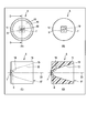
- 2A and 2B show an ultraviolet irradiation module according to an embodiment, where FIG. 2A is a plan view, FIG. 2B is a bottom view, FIG. 2C is a side view, and FIG. 2D is a cross section taken along line DD shown in FIG. It is a figure.
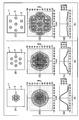
- 3A and 3B show an ultraviolet irradiation unit according to an embodiment, FIG. 3A is a plan view of an ultraviolet irradiation unit including a plurality of ultraviolet irradiation modules arranged in a square lattice, and FIG. 3B is arranged in a hexagonal lattice.
- FIG. 4 is a diagram comparing the distances between the ultraviolet irradiation modules with each other, and (A1) to (C1) are plan views of an ultraviolet irradiation unit including a plurality of ultraviolet irradiation modules arranged in a square lattice. (A2) to (C2) are distribution charts of the ultraviolet irradiation intensity of the ultraviolet irradiation unit at an irradiation distance of 300 mm, and (A3) to (C3) are graphs showing the ultraviolet irradiation intensity of the ultraviolet irradiation unit at an irradiation distance of 300 mm. FIG.
- FIG. 5 is a diagram comparing the distances between the ultraviolet irradiation modules with each other
- (A1) to (C1) are plan views of an ultraviolet irradiation unit including a plurality of ultraviolet irradiation modules arranged in a hexagonal lattice
- (A2) to (C2) are distribution charts of the ultraviolet irradiation intensity of the ultraviolet irradiation unit at an irradiation distance of 300 mm
- (A3) to (C3) are graphs showing the ultraviolet irradiation intensity of the ultraviolet irradiation unit at an irradiation distance of 300 mm.
- FIG. 6 is a view comparing the distances between the ultraviolet irradiation modules
- (A1) to (C1) are plan views of an ultraviolet irradiation unit including a plurality of ultraviolet irradiation modules arranged in a square lattice.
- (A2) to (C2) are distribution charts of the ultraviolet irradiation intensity of the ultraviolet irradiation unit at an irradiation distance of 300 mm
- (A3) to (C3) are graphs showing the ultraviolet irradiation intensity of the ultraviolet irradiation unit at an irradiation distance of 300 mm.
- FIG. 7 is a diagram comparing the distances between the ultraviolet irradiation modules with each other
- (A1) to (C1) are plan views of an ultraviolet irradiation unit including a plurality of ultraviolet irradiation modules arranged in a hexagonal lattice
- (A2) to (C2) are distribution charts of the ultraviolet irradiation intensity of the ultraviolet irradiation unit at an irradiation distance of 300 mm
- (A3) to (C3) are graphs showing the ultraviolet irradiation intensity of the ultraviolet irradiation unit at an irradiation distance of 300 mm.
- FIG. 8 is sectional drawing of the ultraviolet sterilizer of embodiment.
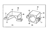
- 9A and 9B are diagrams showing a first example of a reflector used in the embodiment, FIG.
- FIG. 9A is a perspective view of a reflector split portion
- FIG. 9B is a perspective view of a reflector in which the reflector split portion is combined.
- FIG. 10 is a diagram showing how aluminum is deposited on the ultraviolet reflecting surface of the reflector
- FIG. 10A is a sectional view showing how aluminum is deposited on the ultraviolet reflecting surface of the reflector of the embodiment
- FIG. FIG. 5 is a cross-sectional view showing how aluminum is vapor-deposited on the ultraviolet reflecting surface of the reflector of the first example.
- 11A and 11B are views showing a second example of the reflector, where FIG. 11A is a perspective view of the reflector split portion, FIG. 11B is a plan view of a state before the two reflector split portions are assembled, and FIG.
- 11C is a reflector split portion. It is a perspective view of the reflector which combined the part.
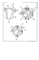
- 12A and 12B are views showing a third example of the reflector, where FIG. 12A is a perspective view of the reflector divided portion, FIG. 12B is a plan view before assembling four reflector divided portions, and FIG. It is a perspective view of the reflector which combined the part.
- 13A and 13B are views showing a fourth example of the reflector, where FIG. 13A is a perspective view of the reflector split portion, FIG. 13B is a plan view of a state before assembling the four reflector split portions, and FIG. It is a perspective view of the reflector which combined the part.
- FIG. 13A is a perspective view of the reflector split portion
- FIG. 13B is a plan view of a state before assembling the four reflector split portions
- FIG. It is a perspective view of the reflector which combined the part.
- FIG. 13A is a perspective view of the reflector split portion
- FIG. 14 is a figure which shows the 5th example of a reflector
- (A) is a perspective view of a reflector division part
- (B) is a perspective view of the reflector which combined the reflector division part.
- 15A and 15B are views showing a sixth example of the reflector, where FIG. 15A is a perspective view of the reflector split portion, FIG. 15B is a plan view of a state before assembling two reflector split portions, and FIG. 15C is a reflector split portion. It is a perspective view of the reflector which combined the part.
- the ultraviolet irradiation unit 1 includes a base 3 and a plurality of ultraviolet irradiation modules 5 arranged on one surface of the base 3 at intervals.
- the ultraviolet irradiation module 5 has a substrate 7 arranged on one surface of the base body 3, a light source 9, and a reflector 11.
- the light source 9 is arranged on one surface of the substrate 7.
- the light source 9 emits ultraviolet rays, and the center wavelength or peak wavelength of the ultraviolet rays emitted from the light source 9 is, for example, 200 nm or more and 350 nm or less.
- the center wavelength or peak wavelength of the ultraviolet light emitted from the light source 9 is preferably 260 nm or more and 290 nm or less from the viewpoint of high sterilization efficiency.
- the type of the light source 9 is not particularly limited as long as it can emit ultraviolet rays.
- the type of the light source 9 is, for example, a light emitting diode (LED), a mercury lamp, a metal halide lamp, a xenon lamp, or a laser diode (LD).
- LED light emitting diode
- LD laser diode
- the reflector 11 is arranged on one surface of the substrate 7 so as to surround the light source 9.
- the reflector 11 includes an ultraviolet reflection surface 13, an ultraviolet emission side surface 15, an ultraviolet emission side opening 17, and a substrate side opening 19.
- the reflector 11 reflects part of the ultraviolet rays emitted from the light source 9 (ultraviolet rays having a large emission angle) toward the object to be processed 21 arranged on the ultraviolet ray emission side.
- the reflector 11 is made of, for example, a polycarbonate resin, an acrylic resin, or a cyclic olefin copolymer (COC).
- At least the surface of the ultraviolet reflecting surface 13 of the reflector 111 is coated with aluminum in a mirror shape.
- the surface of the ultraviolet emitting side surface 15 may be coated to protect the resin from ultraviolet rays.
- the coating of the surfaces of the ultraviolet reflecting surface 13 and the ultraviolet emitting side surface 15 is, for example, aluminum coating by vapor deposition.
- the ultraviolet reflection surface 13 reflects the ultraviolet light emitted from the light source 9 and directly reaching the object 21 to be processed.
- the ultraviolet reflecting surface 13 is a rotation target surface with the central axis 23 as a rotation axis, is circularly symmetric in the present embodiment, and has a concave curved shape with respect to the central axis 23.
- the ultraviolet ray reflection surface 13 may be curved or linear and have a convex shape in the direction of the central axis 23, as long as the purpose of deflecting the ultraviolet rays emitted from the light source 9 toward the object 21 to be processed may be achieved. If the surface of the ultraviolet ray emitting side surface 15 is coated with the same coating as that of the ultraviolet ray reflecting surface 13, a part of the ultraviolet rays that reach the object to be processed 21 and are reflected are reflected toward the object to be processed 21. You can
- the ultraviolet emission side opening 17 is larger than the substrate side opening 19.
- the ultraviolet emission side opening 17 has, for example, a circular shape with a diameter of 15 mm.
- the board-side opening 19 has, for example, a circular shape with a diameter of 2.8 mm.
- the light source 9 is arranged in the center of the substrate-side opening 19.
- the object to be treated 21 is, for example, a gas such as air, a grain such as wheat flour or other powder, a fluid such as liquid such as tap water or agricultural water.
- the plurality of ultraviolet irradiation modules 5 having the light source 9 and the reflector 11 satisfy the following formula (1):
- P is a distance (mm) between one ultraviolet irradiation module 5 and the other ultraviolet irradiation module 5 closest to the one ultraviolet irradiation module 5.
- P is the distance (mm) between the light source 9 of the one ultraviolet irradiation module 5 and the light source 9 of the other ultraviolet irradiation module 5.
- P is, for example, 15 mm to 50 mm.
- L is the irradiation distance (mm) of the ultraviolet rays emitted from the one and the other ultraviolet ray irradiation modules 5. Specifically, L is the distance (mm) from the light source 9 to the irradiated surface 25 of the object 21 to be processed. L is, for example, 20 mm to 1000 mm.
- ⁇ 1 is a half value (°) of the half-width of the directivity angle of the ultraviolet rays emitted from one ultraviolet irradiation module 5.
- the directivity half-width of ultraviolet rays is the angle between the directions in which the intensity of ultraviolet rays is half the maximum value.
- the directivity angle half width of the ultraviolet light emitted from one ultraviolet irradiation module 5 is an angle ⁇ 3 between the shaft 27 and the shaft 29.
- ⁇ 1 is the angle between the central axis 23 and the axis 29, and is also half the value of ⁇ 3.
- ⁇ 1 is, for example, 0.1 ° to 30.0 °.
- ⁇ 2 is a half value (°) of the half-width of the directivity angle of the ultraviolet light emitted from the other ultraviolet irradiation module 5.
- the full width at half maximum of the directivity angle of the ultraviolet light emitted from the other ultraviolet irradiation module 5 is the angle ⁇ 4 between the shaft 31 and the shaft 33.
- ⁇ 2 is the angle between the central axis 23 and the axis 31, and is also half the value of ⁇ 4.
- ⁇ 2 is, for example, 0.1 ° to 30.0 °.
- the plurality of ultraviolet irradiation modules 5 satisfy the following formula (2).
- the ultraviolet irradiation module 5 satisfying the above formula (1) has a part of the ultraviolet light emitted from one ultraviolet irradiation module 5 and the other ultraviolet light on the irradiation surface 25 of the object to be processed 21.
- An ultraviolet ray overlapping portion 35 is generated in which a part of the ultraviolet rays emitted from the irradiation module 5 overlap.
- the ultraviolet ray overlapping portion 35 has a high ultraviolet ray irradiation intensity as compared with a portion where the ultraviolet rays do not overlap, and has an ultraviolet ray irradiation intensity capable of sufficiently sterilizing the object to be treated 21. Therefore, the ultraviolet irradiation module 5 satisfying the above formula (1) can sufficiently sterilize the object to be processed 21 by generating the ultraviolet overlapping portion 35.
- the ultraviolet irradiation module that does not satisfy the above formula (1) cannot generate the ultraviolet overlapping portion, or even if the ultraviolet overlapping portion is generated, the ultraviolet overlapping portion is very small. Further, the ultraviolet irradiation module that does not satisfy the above formula (1) easily causes a region where ultraviolet rays do not reach on the surface to be irradiated of the object to be processed, and thus unevenness of ultraviolet rays is easily generated. Therefore, the ultraviolet ray irradiation module 5 that does not satisfy the above formula (1) cannot emit ultraviolet rays having a high ultraviolet ray irradiation intensity and is likely to cause unevenness of the ultraviolet rays, and thus the object to be treated may not be sufficiently sterilized.
- the ultraviolet irradiation unit 1 may include a plurality of ultraviolet irradiation modules 5 arranged in a square lattice shape in a plan view, as shown in FIG. As shown in FIG. 3B, the ultraviolet irradiation unit 1 may include a plurality of ultraviolet irradiation modules 5 arranged in a hexagonal lattice shape in plan view.
- the ultraviolet irradiation unit 1 includes, for example, 7 to 16 ultraviolet irradiation modules 5. Further, the ultraviolet irradiation unit 1 may be arranged in an oblique lattice shape or a rectangular lattice shape in a plan view.
- the ultraviolet irradiation unit 1 as shown in FIGS. 3A and 3B can be generated in the vicinity of the center of the ultraviolet light that irradiates the ultraviolet overlapping portion having high ultraviolet irradiation intensity. For this reason, such an ultraviolet irradiation unit 1 is arranged to face a fluid flowing in the flow passage pipe, that is, a fluid having a laminar flow that is fast at the center of the pipe and slow at the pipe wall side from a position facing the fluid flow. It is possible to sterilize sufficiently by irradiating with ultraviolet rays having an ultraviolet ray overlapping portion having a high ultraviolet ray irradiation intensity in the vicinity of the center having a high speed.
- the ultraviolet irradiation intensity of the ultraviolet irradiation unit 1 including the plurality of ultraviolet irradiation modules 5 arranged in a square lattice shape or a hexagonal lattice shape in plan view will be described with reference to FIGS. 4 to 7.
- the ultraviolet irradiation unit 1 shown in (A1) to (C1) of FIG. 4 has the same configuration except that the distance between the ultraviolet irradiation modules 5 is different.
- ⁇ 3 is 2.8 ° and L is 300 mm in the above formula (2).
- the ultraviolet irradiation unit 1 satisfying the above formula (2), that is, (1) has an ultraviolet overlapping with high ultraviolet irradiation intensity near the center. It can be seen that ultraviolet rays having parts are generated.
- the ultraviolet irradiation unit 1 that does not satisfy the above formula (2), that is, (1) cannot irradiate ultraviolet rays with high ultraviolet irradiation intensity near the center.
- the ultraviolet irradiation unit 1 shown in (A1) to (C1) of FIG. 5 has the same configuration except that the distance between the ultraviolet irradiation modules 5 is different.
- Each of the ultraviolet irradiation units 1 shown in (A1) to (C1) of FIG. 5 has ⁇ 3 of 2.8 ° and L of 300 mm in the above formula (2).
- the ultraviolet irradiation unit 1 satisfying the above formula (2), that is, (1) has an ultraviolet overlapping with high ultraviolet irradiation intensity near the center. It can be seen that ultraviolet rays having parts are generated.
- the ultraviolet irradiation unit 1 that does not satisfy the above formula (2), that is, (1) cannot irradiate ultraviolet light with high ultraviolet irradiation intensity near the center.
- the ultraviolet irradiation unit 1 shown in (A1) to (C1) of FIG. 6 has the same configuration except that the distance between the ultraviolet irradiation modules 5 is different.
- Each of the ultraviolet irradiation units 1 shown in (A1) to (C1) of FIG. 6 has ⁇ 3 of 5.7 ° and L of 300 mm in the above formula (2).
- the ultraviolet irradiation unit 1 satisfying the above formula (2), that is, (1) has an ultraviolet overlapping with high ultraviolet irradiation intensity near the center. It can be seen that ultraviolet rays having parts are generated.
- the ultraviolet irradiation unit 1 which does not satisfy the above formula (2), that is, (1) cannot irradiate the ultraviolet light of high ultraviolet irradiation intensity near the center.
- the ultraviolet irradiation unit 1 shown in (A1) to (C1) of FIG. 7 has the same configuration except that the distance between the ultraviolet irradiation modules 5 is different.
- ⁇ 3 is 5.7 ° and L is 300 mm in the above formula (2).
- the ultraviolet irradiation unit 1 satisfying the above formula (2), that is, (1) has an ultraviolet overlapping with high ultraviolet irradiation intensity near the center. It can be seen that ultraviolet rays having parts are generated.
- the ultraviolet irradiation unit 1 that does not satisfy the above formula (2), that is, (1) cannot irradiate ultraviolet light with high ultraviolet irradiation intensity near the center.
- the ultraviolet sterilizer 41 has an ultraviolet irradiation unit 1 and a flow path pipe 43.
- the flow channel tube 43 has an inflow portion 45, a flow channel tube body 47, an outflow portion 49, and an ultraviolet ray incident window 51.
- the flow path pipe 43 is a pipe through which the fluid to be sterilized flows.
- the flow path tube 43 is formed of a material such as polypropylene (PP), polytetrafluoroethylene (PTFE), stainless steel, or aluminum that is not easily deformed or damaged by the pressure of the fluid.
- the inflow section 45 has an inflow channel 53 inside.
- the upstream end of the inflow portion 45 is an inflow port 55 for allowing the fluid to flow into the inflow passage 53.
- the downstream end of the inflow portion 45 is connected to the pipe wall at the upstream end of the flow path pipe body 47.
- the inflow portion 45 is connected to a fluid supply device or the like (not shown) via the inflow port 55, and guides the fluid from the fluid supply device to the flow path tube body 47.
- the inflow port 55 may have a shape into which a hose for guiding the fluid to the inflow passage 53 can be fitted.
- the inflow part 45 introduces a fluid that is sterilized by irradiation of ultraviolet rays into the flow path tube body 47.
- the flow path tube main body 47 has therein a processing flow path 57 that flows from one end side toward the other end side.
- the shape of the flow path tube body 47 is not particularly limited as long as the fluid can flow.
- the shape of the processing channel 57 may be linear or curved. In the present embodiment, the processing channel 57 has a linear shape.
- the cross-sectional shape of the processing channel 57 in the direction perpendicular to the direction in which the fluid flows is not particularly limited.
- the cross-sectional shape may be circular or polygonal. In the present embodiment, the cross-sectional shape of the processing channel 57 in the direction perpendicular to the direction in which the fluid flows is circular.
- the flow path tube body 47 may be of any size as long as it can sufficiently sterilize the fluid by irradiation of ultraviolet rays.
- the flow path tube body 47 can have a flow path length of 2 cm or more and 100 cm or less, for example.
- the outflow portion 49 has an outflow passage 59 inside.
- the upstream end of the outflow portion 49 is connected to the vicinity of the downstream end of the flow path pipe body 47.
- the downstream end of the outflow portion 49 is an outlet 61 for guiding to a liquid storage device or the like (not shown).
- the outlet 61 is connected to the liquid storage device and guides the fluid from the processing channel 57 to the liquid storage device or the like.
- the outlet 61 may have a shape into which a hose for guiding the fluid to the liquid storage device can be fitted.
- the outflow section 49 causes the sterilized fluid to flow out from the processing flow path 57.
- the ultraviolet incident window 51 is fitted into the downstream end opening of the flow path tube body 47.
- the ultraviolet ray incident window 51 allows the ultraviolet rays emitted from the ultraviolet ray irradiation unit 1 to pass through the flow channel tube 43 (flow channel tube body 47).
- the ultraviolet incident window 51 is formed of a material having a high transmittance for ultraviolet rays, such as quartz (SiO 2 ), sapphire (Al 2 O 3 ), and an amorphous fluorine resin.
- the fluid introduced from the inflow port 55 to the processing flow path 57 via the inflow flow path 53 is irradiated with the ultraviolet rays emitted from the ultraviolet irradiation unit 1 while flowing through the processing flow path 57, and is sterilized.
- the irradiation direction of the ultraviolet rays emitted from the ultraviolet irradiation unit 1 is preferably opposed to the fluid flow. Then, the sterilized fluid is discharged from the outflow port 61 via the outflow passage 59.
- the flow rate of the fluid may be a speed that is sufficiently sterilized by irradiation of ultraviolet rays while flowing through the processing flow path 57, and is, for example, 5 L / min to 100 L / min or less.
- an ultraviolet sterilizer 41 includes the ultraviolet irradiation unit 1 described above, it is effective for a fluid flowing through the flow path pipe, that is, for a laminar flow fluid that is fast at the center of the pipe and slow at the pipe wall side. Sufficient sterilization can be achieved by irradiating from the position facing the flow of the fluid with ultraviolet rays having an ultraviolet ray overlapping portion with high ultraviolet ray irradiation intensity in the vicinity of the center.
- the reflector 63 of the first example is composed of two reflector division parts 65.
- the reflector dividing portion 65 has an ultraviolet reflecting surface 67, an ultraviolet emitting side surface 69, a screw hole 71, and an engaging surface 73.
- the engagement surface 73 of the one reflector split portion 65 and the engagement surface 73 of the other reflector split portion 65 are aligned with each other, for example, a screw (not shown) is inserted into the screw hole 71, and the nut It is fixed by (not shown).
- the direction of the ultraviolet reflecting surface 67 can be arbitrarily set when the aluminum is coated by vapor deposition on the ultraviolet reflecting surface 67.
- the direction in which the aluminum vapor deposition material 74 faces and the ultraviolet rays are the direction in which the aluminum vapor deposition material 74 faces and the ultraviolet reflecting surface 13 when aluminum is coated on the ultraviolet reflecting surface 13 of the reflector 11 by vapor deposition.
- the angle can be made smaller than the angles ⁇ 5, ⁇ 6, and ⁇ 7 formed by the normal line. Therefore, it is easy to vapor-deposit aluminum to a desired thickness on the ultraviolet reflecting surface 67 of the reflector dividing portion 65. Therefore, according to the reflector dividing section 65, a desired reflectance can be given to the ultraviolet reflecting surface 67.
- the reflector 63a of the second example will be described with reference to FIG.
- the reflector 63a of the second example differs from the reflector 63 of the first example only in the configuration of the reflector dividing portion 65a. Therefore, in the configuration of the reflector 63a of the second example, the same components as those of the reflector 63 of the first example are designated by the same reference numerals, and the description thereof will be omitted.
- the reflector 63a of the second example has two reflector division parts 65a.
- the reflector dividing portion 65a has a positioning pin 75 and a positioning hole 77.
- the positioning pin 75 of the one reflector split portion 65a is inserted into the positioning hole 77 of the other reflector split portion 65a, and subsequently, the engagement surface 73 of the one reflector split portion 65a and the other reflector split portion.
- the engagement surface 73 of 65a is matched.
- Such a reflector 63a of the second example has the same effect as that of the reflector 63 of the first example, and the positioning pin 75 of the one reflector split portion 65a is inserted into the positioning hole 77 of the other reflector split portion 65a. Therefore, it is easily formed without shifting.
- the reflector 79 of the third example is composed of four reflector divisions 81.
- the reflector dividing section 81 has an ultraviolet reflecting surface 83, an ultraviolet emitting side surface 85, a screw hole 87, and an engaging surface 89.
- the engagement surface 89 of the one reflector divided portion 81 and the engagement surface 89 of the other reflector divided portion 81 are aligned with each other, and for example, a screw (not shown) is inserted into the screw hole 87 and a nut ( (Not shown).
- Such a reflector 79 of the third example has the same effect as the reflector 63 of the first example.
- the reflector 79a of the fourth example will be described with reference to FIG.
- the reflector 79a of the fourth example differs from the reflector 79 of the third example only in the configuration of the reflector dividing portion 81a. Therefore, in the configurations of the reflector 79a and the reflector dividing portion 81a of the fourth example, the same configurations as those of the reflector 79 of the third example are denoted by the same reference numerals, and the description thereof will be omitted.
- the reflector 79a of the fourth example has four reflector divisions 81a.
- the reflector dividing portion 81a has a positioning pin 91 and a positioning hole 93.
- the positioning pin 91 of the one reflector split portion 81a is inserted into the positioning hole 93 of the other reflector split portion 81a, and subsequently, the engagement surface 89 of the one reflector split portion 81a and the other reflector split portion.
- the engagement surface 89 of 81a is matched.
- Such a reflector 79a of the fourth example has the same effect as that of the reflector 79 of the third example, and the positioning pin 91 of one reflector divided portion 81a is inserted into the positioning hole 93 of the other reflector divided portion 81a. Therefore, it is easily formed without shifting.
- the reflector 95 of the fifth example is one in which three reflector portions are integrally formed, and is composed of two reflector divided portions 97.
- the reflector dividing portion 97 has an ultraviolet reflecting surface 99, an ultraviolet emitting side surface 101, a screw hole 103, and an engaging surface 105.
- the engagement surface 105 of the one reflector divided portion 97 and the engagement surface 105 of the other reflector divided portion 97 are aligned with each other, and for example, a screw (not shown) is inserted into the screw hole 103 and a nut ( (Not shown).
- Such a reflector 95 of the fifth example has the same effect as the reflector 63 of the first example, and can simultaneously form three reflector portions.
- the reflector 95a of the sixth example will be described with reference to FIG.
- the reflector 95a of the sixth example differs from the reflector 95 of the fifth example only in the configuration of the reflector dividing portion 97a. Therefore, in the configuration of the reflector 95a and the reflector dividing portion 97a of the sixth example, the same components as those of the reflector 95 of the fifth example are denoted by the same reference numerals, and the description thereof will be omitted.
- the reflector 95a of the sixth example has two reflector divisions 97a.
- the reflector dividing portion 97a has a positioning pin 107 and a positioning hole 109.
- the positioning pin 107 of the one reflector divided portion 97a is inserted into the positioning hole 109 of the other reflector divided portion 97a, and subsequently, the engagement surface 105 of the one reflector divided portion 97a and the other reflector divided portion.
- the engagement surface 105 of 97a is matched.
- Such a reflector 95a of the sixth example has the same effect as that of the reflector 95 of the fifth example, and the positioning pin 107 of one reflector split portion 97a is inserted into the positioning hole 109 of the other reflector split portion 97a. Therefore, it is easily formed without shifting.
Landscapes
- Health & Medical Sciences (AREA)
- Chemical & Material Sciences (AREA)
- Toxicology (AREA)
- Engineering & Computer Science (AREA)
- Life Sciences & Earth Sciences (AREA)
- General Chemical & Material Sciences (AREA)
- Chemical Kinetics & Catalysis (AREA)
- Environmental & Geological Engineering (AREA)
- Organic Chemistry (AREA)
- Analytical Chemistry (AREA)
- Hydrology & Water Resources (AREA)
- Oil, Petroleum & Natural Gas (AREA)
- Water Supply & Treatment (AREA)
- Epidemiology (AREA)
- Animal Behavior & Ethology (AREA)
- General Health & Medical Sciences (AREA)
- Public Health (AREA)
- Veterinary Medicine (AREA)
- Apparatus For Disinfection Or Sterilisation (AREA)
- Physical Water Treatments (AREA)
Abstract
本発明の紫外線照射ユニットは、互いに間隔をあけて配置された複数の紫外線照射モジュールを有する。各紫外線照射モジュールは、紫外線を出射する光源と、光源の紫外線出射側に配置され、光源から出射された紫外線のうち、一部の紫外線を被処理体に向けて反射するリフレクターとを備える。複数の紫外線照射モジュールは、下記式(1)を満たす。 P/L(tanθ1+tanθ2)≦1 (1) 式(1)中、Pは、一方及び他方の紫外線照射モジュールの間の距離(mm)、Lは、一方及び他方の紫外線照射モジュールから出射された紫外線の照射距離(mm)、θ1、θ2は、それぞれ一方又は他方の紫外線照射モジュールから出射された紫外線の指向角半値幅の半分の値(°)である。
Description
本発明は、紫外線照射ユニット及び紫外線殺菌装置に関する。
紫外線を用いて流路管内の流体を殺菌処理することが広く知られている。例えば、特表2016-531746号公報には、紫外線を均一に分散させて流路管内の流体を殺菌処理している。
しかし、流路管を流れる流体は、一般に層流では管の中央では速く、管壁側では遅く、均一な速度で流れていないため、従来の紫外線殺菌装置では殺菌にむらが生じ、流体を十分に殺菌できないおそれがあった。
そこで本発明は、流体をむら無く十分に殺菌できる紫外線照射ユニット及び流路管を流れる流体を十分に殺菌できる紫外線殺菌装置の提供を目的とする。
上記の課題を解決するための、本発明に関する紫外線照射ユニットは、被処理体に紫外線を照射して殺菌処理する紫外線照射ユニットであって、互いに間隔をあけて配置された、紫外線を出射する複数の紫外線照射モジュールを有する。各紫外線照射モジュールは、紫外線を出射する光源と、前記光源の紫外線出射側に配置され、前記光源から出射された紫外線のうち、一部の紫外線を前記被処理体に向けて反射するリフレクターとを備える。前記複数の紫外線照射モジュールは、下記式(1)を満たす。
P/L(tanθ1+tanθ2)≦1 (1)
式(1)中、Pは、一方の紫外線照射モジュールと、前記一方の紫外線照射モジュールに最も近い他方の紫外線照射モジュールとの距離(mm)であり、Lは、前記一方及び他方の紫外線照射モジュールから出射された紫外線の照射距離(mm)であり、θ1は、前記一方の紫外線照射モジュールから出射された紫外線の指向角半値幅の半分の値(°)であり、θ2は、前記他方の紫外線照射モジュールから出射された紫外線の指向角半値幅の半分の値(°)である。
式(1)中、Pは、一方の紫外線照射モジュールと、前記一方の紫外線照射モジュールに最も近い他方の紫外線照射モジュールとの距離(mm)であり、Lは、前記一方及び他方の紫外線照射モジュールから出射された紫外線の照射距離(mm)であり、θ1は、前記一方の紫外線照射モジュールから出射された紫外線の指向角半値幅の半分の値(°)であり、θ2は、前記他方の紫外線照射モジュールから出射された紫外線の指向角半値幅の半分の値(°)である。
また、上記の課題を解決するための、本発明に関する紫外線殺菌装置は、流路管を流れる被処理体に対して紫外線を照射して殺菌処理する紫外線殺菌装置であって、流路管と、上述した紫外線照射ユニットとを備える。
以下、本発明の実施の形態について、図面を参照して詳細に説明する。
[実施の形態]
図1及び図2に示すように、紫外線照射ユニット1は、基体3と、基体3の一方の面に互いに間隔をあけて配置された、複数の紫外線照射モジュール5とを有する。紫外線照射モジュール5は、基体3の一方の面に配置された基板7と、光源9と、リフレクター11とを有する。
図1及び図2に示すように、紫外線照射ユニット1は、基体3と、基体3の一方の面に互いに間隔をあけて配置された、複数の紫外線照射モジュール5とを有する。紫外線照射モジュール5は、基体3の一方の面に配置された基板7と、光源9と、リフレクター11とを有する。
光源9は、基板7の一方の面に配置されている。光源9は、紫外線を出射し、光源9から出射される紫外線の中心波長又はピーク波長は、例えば、200nm以上350nm以下である。光源9から出射される紫外線の中心波長又はピーク波長は、殺菌効率が高い観点から、260nm以上290nm以下であることが好ましい。光源9の種類は、紫外線を出射できれば特に限定されない。光源9の種類は、例えば、発光ダイオード(LED)、水銀ランプ、メタルハライドランプ、キセノンランプ、レーザーダイオード(LD)である。
リフレクター11は、基板7の一方の面に、光源9の周囲を囲むように配置されている。リフレクター11は、紫外線反射面13と、紫外線出射側面15と、紫外線出射側開口部17と、基板側開口部19とを備えている。リフレクター11は、光源9から出射された紫外線のうち、一部の紫外線(出射角度が大きな紫外線)を紫外線出射側に配置された被処理体21に向けて反射する。リフレクター11は、例えば、ポリカーボネート樹脂、アクリル樹脂、環状オレフィンコポリマー(COC)から形成されている。リフレクター111は、少なくとも紫外線反射面13の表面はアルミニウムでミラー状にコーティングされている。紫外線出射側面15の表面は、紫外線から樹脂を保護するためにコーティングされていてもよい。紫外線反射面13と紫外線出射側面15の表面のコーティングは、例えば、蒸着によるアルミニウムコーティングが挙げられる。
紫外線反射面13は、光源9から出射され、直接到達した紫外線を被処理体21に向けて反射する。紫外線反射面13は、中心軸23を回転軸とした回転対象面であり、本実施の形態では円対称であり、中心軸23に対して凹の曲線状である。紫外線反射面13は、中心軸23の方向に凸の曲線状や直線状であってもよく、光源9から出射された紫外線を被処理体21に向けて偏向する目的が達成されればよい。紫外線出射側面15は、その表面に紫外線反射面13と同一のコーティングが施されていれば、被処理体21に到達して反射した一部の紫外線を、被処理体21に向けて反射することができる。
紫外線出射側開口部17は、基板側開口部19と比較して大きく開口している。紫外線出射側開口部17は、例えば、直径15mmの円形状である。基板側開口部19は、例えば、直径2.8mmの円形状である。基板側開口部19の中央には、光源9が配置されている。
被処理体21は、例えば、空気等の気体、小麦粉のような穀物やその他の粉体、上水や農業用水のような液体等の流体である。
このような光源9とリフレクター11とを有する、複数の紫外線照射モジュール5は、下記式(1):を満たす。
P/L(tanθ1+tanθ2)≦1 (1)
図1に示すように、上記式(1)において、Pは、一方の紫外線照射モジュール5と、一方の紫外線照射モジュール5に最も近い他方の紫外線照射モジュール5との距離(mm)である。具体的には、Pは、一方の紫外線照射モジュール5の光源9と、他方の紫外線照射モジュール5の光源9との距離(mm)である。Pは、例えば、15mm~50mmである。
図1に示すように、上記式(1)において、Pは、一方の紫外線照射モジュール5と、一方の紫外線照射モジュール5に最も近い他方の紫外線照射モジュール5との距離(mm)である。具体的には、Pは、一方の紫外線照射モジュール5の光源9と、他方の紫外線照射モジュール5の光源9との距離(mm)である。Pは、例えば、15mm~50mmである。
上記式(1)において、Lは、一方及び他方の紫外線照射モジュール5から出射された紫外線の照射距離(mm)である。具体的には、Lは、光源9から被処理体21の被照射面25までの距離(mm)である。Lは、例えば、20mm~1000mmである。
上記式(1)において、θ1は、一方の紫外線照射モジュール5から出射された紫外線の指向角半値幅の半分の値(°)である。紫外線の指向角半値幅は、紫外線の強度が最大値の半分となる方向間の角度である。具体的には、一方の紫外線照射モジュール5から出射された紫外線の指向角半値幅は、軸27と軸29との間の角度θ3である。θ1は中心軸23と軸29との間の角度であり、θ3の半分の値でもある。θ1は、例えば、0.1°~30.0°である。
上記式(1)において、θ2は、他方の紫外線照射モジュール5から出射された紫外線の指向角半値幅の半分の値(°)である。具体的には、他方の紫外線照射モジュール5から出射された紫外線の指向角半値幅は、軸31と軸33との間の角度θ4である。θ2は中心軸23と軸31との間の角度であり、θ4の半分の値でもある。θ2は、例えば、0.1°~30.0°である。
上記式(1)においてθ1及びθ2が同一である場合、複数の紫外線照射モジュール5は、下記式(2)を満たす。
P/Ltanθ3≦2 (2)
上記式(2)において、P及びLは、式(1)で定義した通りであり、θ3は、式(1)で定義したθ1又はθ2と同じ定義を有する。θ3は、例えば、θ1及びθ2と同様に0.1°~30.0°である。
上記式(2)において、P及びLは、式(1)で定義した通りであり、θ3は、式(1)で定義したθ1又はθ2と同じ定義を有する。θ3は、例えば、θ1及びθ2と同様に0.1°~30.0°である。
図1に示すように、上記式(1)を満たす紫外線照射モジュール5は、被処理体21の被照射面25において、一方の紫外線照射モジュール5から出射された紫外線の一部と、他方の紫外線照射モジュール5から出射された紫外線の一部とが重なる、紫外線重複部35を発生させる。紫外線重複部35は、紫外線が重複していないところと比較して紫外線照射強度が高く、被処理体21を十分に殺菌できる紫外線照射強度を有する。このため、上記式(1)を満たす紫外線照射モジュール5は、紫外線重複部35を発生させることにより、被処理体21を十分に殺菌できる。
一方、上記式(1)を満たさない紫外線照射モジュールは、紫外線重複部を発生させることができないか、紫外線重複部を発生させてもその紫外線重複部は非常に小さい。また、上記式(1)を満たさない紫外線照射モジュールは、被処理体の被照射面において紫外線が到達しない領域を発生させ、紫外線のむらを発生させやすい。このため、上記式(1)を満たさない紫外線照射モジュール5は、高い紫外線照射強度の紫外線を照射できず、紫外線のむらを発生させやすいため被処理体を十分に殺菌できないおそれがある。
紫外線照射ユニット1は、図3の(A)に示すように、平面視において正方格子状に配置された複数の紫外線照射モジュール5を備えてもよい。図3の(B)に示すように、紫外線照射ユニット1は、平面視において六方格子状に配置された複数の紫外線照射モジュール5を備えてもよい。紫外線照射ユニット1は、例えば、7~16個の紫外線照射モジュール5を備える。また、紫外線照射ユニット1は、平面視において、斜方格子状、又は長方格子状に配置されてもよい。
図3の(A)及び(B)に示すような紫外線照射ユニット1は、紫外線照射強度の高い紫外線重複部を照射する紫外線の中心付近に発生させることができる。このため、このような紫外線照射ユニット1は、流路管を流れる流体に対して、すなわち管の中央では速く、管壁側では遅い層流の流体に対して、流体の流れに対向する位置から、速度の速い中心付近に紫外線照射強度の高い紫外線重複部を有する紫外線を照射することによって十分に殺菌することができる。
以下、平面視において正方格子状又は六方格子状に配置された複数の紫外線照射モジュール5を備える紫外線照射ユニット1の紫外線照射強度について、図4~図7を参照して説明する。
図4の(A1)~(C1)に示す紫外線照射ユニット1は、紫外線照射モジュール5間の距離が異なること以外は同じ構成を有する。図4の(A1)~(C1)に示す各紫外線照射ユニット1は、上記式(2)においてθ3が2.8°、Lが300mmである。
図4の(A1)に示す各紫外線照射モジュール5間の距離であるPは、15.0mmである。したがって、図4の(A1)に示す紫外線照射ユニット1は、
P/Ltanθ3=1.02<2
である。
P/Ltanθ3=1.02<2
である。
図4の(B1)に示す各紫外線照射モジュール5間の距離であるPは、22.5mmである。したがって、図4の(B1)に示す紫外線照射ユニット1は、
P/Ltanθ3=1.53<2
である。
P/Ltanθ3=1.53<2
である。
図4の(C1)に示す各紫外線照射モジュール5間の距離であるPは、30.0mmである。したがって、図4の(C1)に示す紫外線照射ユニット1は、
P/Ltanθ3=2.04>2
である。
P/Ltanθ3=2.04>2
である。
図4の(A2)、(A3)、(B2)、(B3)に示すように、上記式(2)すなわち(1)を満たす紫外線照射ユニット1は、中心付近に紫外線照射強度の高い紫外線重複部を有する紫外線を発生させていることがわかる。
一方、図4の(C2)、(C3)に示すように、上記式(2)すなわち(1)を満たさない紫外線照射ユニット1は、中心付近に高い紫外線照射強度の紫外線を照射できない。
図5の(A1)~(C1)に示す紫外線照射ユニット1は、紫外線照射モジュール5間の距離が異なること以外は同じ構成を有する。図5の(A1)~(C1)に示す各紫外線照射ユニット1は、上記式(2)においてθ3が2.8°、Lが300mmである。
図5の(A1)に示す各紫外線照射モジュール5間の距離であるPは、15.0mmである。したがって、図5の(A1)に示す紫外線照射ユニット1は、
P/Ltanθ3=1.02<2
である。
P/Ltanθ3=1.02<2
である。
図5の(B1)に示す各紫外線照射モジュール5間の距離であるPは、22.5mmである。したがって、図5の(B1)に示す紫外線照射ユニット1は、
P/Ltanθ3=1.53<2
である。
P/Ltanθ3=1.53<2
である。
図5の(C1)に示す各紫外線照射モジュール5間の距離であるPは、30.0mmである。したがって、図5の(C1)に示す紫外線照射ユニット1は、
P/Ltanθ3=2.04>2
である。
P/Ltanθ3=2.04>2
である。
図5の(A2)、(A3)、(B2)、(B3)に示すように、上記式(2)すなわち(1)を満たす紫外線照射ユニット1は、中心付近に紫外線照射強度の高い紫外線重複部を有する紫外線を発生させていることがわかる。
一方、図5の(C2)、(C3)に示すように、上記式(2)すなわち(1)を満たさない紫外線照射ユニット1は、中心付近に高い紫外線照射強度の紫外線を照射できない。
図6の(A1)~(C1)に示す紫外線照射ユニット1は、紫外線照射モジュール5間の距離が異なること以外は同じ構成を有する。図6の(A1)~(C1)に示す各紫外線照射ユニット1は、上記式(2)においてθ3が5.7°、Lが300mmである。
図6の(A1)に示す各紫外線照射モジュール5間の距離であるPは、15.0mmである。したがって、図6の(A1)に示す紫外線照射ユニット1は、
P/Ltanθ3=0.50<2
である。
P/Ltanθ3=0.50<2
である。
図6の(B1)に示す各紫外線照射モジュール5間の距離であるPは、37.5mmである。したがって、図6の(B1)に示す紫外線照射ユニット1は、
P/Ltanθ3=1.25<2
である。
P/Ltanθ3=1.25<2
である。
図6の(C1)に示す各紫外線照射モジュール5間の距離であるPは、60.0mmである。したがって、図6の(C1)に示す紫外線照射ユニット1は、
P/Ltanθ3=2.01>2
である。
P/Ltanθ3=2.01>2
である。
図6の(A2)、(A3)、(B2)、(B3)に示すように、上記式(2)すなわち(1)を満たす紫外線照射ユニット1は、中心付近に紫外線照射強度の高い紫外線重複部を有する紫外線を発生させていることがわかる。
一方、図6の(C2)、(C3)に示すように、上記式(2)すなわち(1)を満たさない紫外線照射ユニット1は、中心付近に高い紫外線照射強度の紫外線を照射できない。
図7の(A1)~(C1)に示す紫外線照射ユニット1は、紫外線照射モジュール5間の距離が異なること以外は同じ構成を有する。図7の(A1)~(C1)に示す各紫外線照射ユニット1は、上記式(2)においてθ3が5.7°、Lが300mmである。
図7の(A1)に示す各紫外線照射モジュール5間の距離であるPは、15.0mmである。したがって、図7の(A1)に示す紫外線照射ユニット1は、
P/Ltanθ3=0.50<2
である。
P/Ltanθ3=0.50<2
である。
図7の(B1)に示す各紫外線照射モジュール5間の距離であるPは、37.5mmである。したがって、図7の(B1)に示す紫外線照射ユニット1は、
P/Ltanθ3=1.25<2
である。
P/Ltanθ3=1.25<2
である。
図7の(C1)に示す各紫外線照射モジュール5間の距離であるPは、60.0mmである。したがって、図7の(C1)に示す紫外線照射ユニット1は、
P/Ltanθ3=2.01>2
である。
P/Ltanθ3=2.01>2
である。
図7の(A2)、(A3)、(B2)、(B3)に示すように、上記式(2)すなわち(1)を満たす紫外線照射ユニット1は、中心付近に紫外線照射強度の高い紫外線重複部を有する紫外線を発生させていることがわかる。
一方、図7の(C2)、(C3)に示すように、上記式(2)すなわち(1)を満たさない紫外線照射ユニット1は、中心付近に高い紫外線照射強度の紫外線を照射できない。
図8に示すように、紫外線殺菌装置41は、紫外線照射ユニット1と、流路管43とを有する。
流路管43は、流入部45と、流路管本体47と、流出部49と、紫外線入射窓51とを有する。流路管43は、殺菌処理される流体が流れる管である。流路管43は、例えば、ポリプロピレン(PP)、ポリテトラフルオロエチレン(PTFE)、ステンレス鋼、アルミニウムのような、流体の圧力によって変形又は破損しにくい材料から形成される。
流入部45は、内部に流入流路53を有する。流入部45の上流側端部は、流体を流入流路53に流入させるための流入口55である。流入部45の下流側端部は、流路管本体47の上流側端部の管壁に接続している。流入部45は、流入口55を介して流体供給装置など(図示せず)に接続され、流体供給装置からの流体を流路管本体47に導く。流入口55は、流体を流入流路53に導くためのホースを嵌め込み可能な形状を有してもよい。流入部45は、紫外線の照射により殺菌処理される流体を流路管本体47に導入する。
流路管本体47は、一方の端部側から他方の端部側に向けて流れる処理流路57を内部に有する。流路管本体47の形状は、流体が流れることができれば特に限定されない。処理流路57の形状は、直線状でもよいし、曲線状でもよい。本実施の形態では、処理流路57の形状は、直線状である。また、処理流路57の流体が流れる方向に垂直な方向の断面形状も特に限定されない。当該断面形状は、円形でもよいし、多角形でもよい。本実施の形態では、処理流路57の流体が流れる方向に垂直な方向の断面形状は、円形である。流路管本体47は、紫外線の照射により流体を十分に殺菌処理できる大きさであればよい。流路管本体47は、例えば、流路長を2cm以上100cm以下にできる。
流出部49は、内部に流出流路59を有する。流出部49の上流側端部は、流路管本体47の下流側端部近傍に接続している。流出部49の下流側端部は、液体貯蔵装置など(図示せず)に導くための流出口61である。流出口61は、液体貯蔵装置に接続され、処理流路57からの流体を液体貯蔵装置などに導く。流出口61は、流体を液体貯蔵装置に導くためのホースを嵌め込み可能な形状を有してもよい。流出部49は、殺菌処理された流体を処理流路57から流出させる。
紫外線入射窓51は、流路管本体47の下流側の端部開口に嵌め込まれている。紫外線入射窓51は、紫外線照射ユニット1から出射された紫外線を流路管43(流路管本体47)内に透過させる。紫外線入射窓51は、例えば、石英(SiO2)、サファイア(Al2O3)、非晶質のフッ素系樹脂のような紫外線に対する透過率が高い材料から形成される。
流入口55から流入流路53を経由して処理流路57に導入された流体は、処理流路57を流れている間に、紫外線照射ユニット1から出射された紫外線を照射され、殺菌処理される。ここで、紫外線照射ユニット1から出射された紫外線の照射方向は、流体の流れに対して対向することが好ましい。その後、殺菌処理された流体は、流出流路59を経由して流出口61から排出される。
流体の流速は、処理流路57を流れる間の紫外線の照射によって十分に殺菌される速さであればよく、例えば、5L/min~100L/min以下である。
このような紫外線殺菌装置41は、上述した紫外線照射ユニット1を備えているため、流路管を流れる流体に対して、すなわち管の中央では速く、管壁側では遅い層流の流体に対して、流体の流れに対向する位置から、中心付近に紫外線照射強度の高い紫外線重複部を有する紫外線を照射することによって十分に殺菌することができる。
図9に示すように、第1例のリフレクター63は、2つのリフレクター分割部65で構成されている。リフレクター分割部65は、紫外線反射面67と、紫外線出射側面69と、ネジ穴71と、係合面73とを有する。リフレクター63は、一方のリフレクター分割部65の係合面73と、他方のリフレクター分割部65の係合面73とを合わせて、例えば、ネジ穴71にネジ(図示せず)を挿通し、ナット(図示せず)で固定される。
第1例のリフレクター63のように分割して構成することによって、紫外線反射面67に対して、蒸着によりアルミニウムコーティングするときに紫外線反射面67の向きを任意に設定できる。
即ち、図10の(A)及び(B)に示すように、第1例のリフレクター分割部65の紫外線反射面67への蒸着によるアルミニウムコーティング時の、アルミニウム蒸着物質74が向かってくる方向と紫外線反射面13の法線のなす角度θ8、θ9、θ10は、実施の形態のリフレクター11の紫外線反射面13への蒸着によるアルミニウムコーティング時の、アルミニウム蒸着物質74が向かってくる方向と紫外線反射面13の法線のなす角度θ5、θ6、θ7と比較して小さくできる。このため、リフレクター分割部65の紫外線反射面67に、アルミニウムを所望の厚さに蒸着させやすい。したがってリフレクター分割部65によれば、紫外線反射面67に所望の反射率を付与することができる。
図11を参照して、第2例のリフレクター63aについて説明する。第2例のリフレクター63aは、リフレクター分割部65aの構成のみが第1例のリフレクター63と異なる。そこで、第2例のリフレクター63aの構成において、第1例のリフレクター63と同様の構成については、同じ符号を付してその説明を省略する。
第2例のリフレクター63aは、2つのリフレクター分割部65aを有する。リフレクター分割部65aは、位置決めピン75と、位置決め穴77とを有する。リフレクター63aは、一方のリフレクター分割部65aの位置決めピン75を、他方のリフレクター分割部65aの位置決め穴77に挿入し、続いて一方のリフレクター分割部65aの係合面73と、他方のリフレクター分割部65aの係合面73とを合わせる。
このような、第2例のリフレクター63aは、第1例のリフレクター63と同様の効果を有するとともに、一方のリフレクター分割部65aの位置決めピン75を、他方のリフレクター分割部65aの位置決め穴77に挿入するため、ずれることなく且つ容易に形成される。
図12に示すように、第3例のリフレクター79は、4つのリフレクター分割部81で構成されている。リフレクター分割部81は、紫外線反射面83と、紫外線出射側面85と、ネジ穴87と、係合面89とを有する。リフレクター79は、一方のリフレクター分割部81の係合面89と、他方のリフレクター分割部81の係合面89とを合わせて、例えば、ネジ穴87にネジ(図示せず)を挿通しナット(図示せず)で固定される。
このような、第3例のリフレクター79は、第1例のリフレクター63と同様の効果を有する。
図13を参照して、第4例のリフレクター79aについて説明する。第4例のリフレクター79aは、リフレクター分割部81aの構成のみが第3例のリフレクター79と異なる。そこで、第4例のリフレクター79a及びリフレクター分割部81aの構成において、第3例のリフレクター79と同様の構成については、同じ符号を付してその説明を省略する。
第4例のリフレクター79aは、4つのリフレクター分割部81aを有する。リフレクター分割部81aは、位置決めピン91と、位置決め穴93とを有する。リフレクター79aは、一方のリフレクター分割部81aの位置決めピン91を、他方のリフレクター分割部81aの位置決め穴93に挿入し、続いて一方のリフレクター分割部81aの係合面89と、他方のリフレクター分割部81aの係合面89とを合わせる。
このような、第4例のリフレクター79aは、第3例のリフレクター79と同様の効果を有するとともに、一方のリフレクター分割部81aの位置決めピン91を、他方のリフレクター分割部81aの位置決め穴93に挿入するため、ずれることなく且つ容易に形成される。
図14に示すように、第5例のリフレクター95は、3つのリフレクター部分を一体に形成したものであり、2つのリフレクター分割部97で構成されている。リフレクター分割部97は、紫外線反射面99と、紫外線出射側面101と、ネジ穴103と、係合面105とを有する。リフレクター95は、一方のリフレクター分割部97の係合面105と、他方のリフレクター分割部97の係合面105とを合わせて、例えば、ネジ穴103にネジ(図示せず)を挿通しナット(図示せず)で固定される。
このような、第5例のリフレクター95は、第1例のリフレクター63と同様の効果を有するとともに、3つのリフレクター部分を同時に形成できる。
図15を参照して、第6例のリフレクター95aについて説明する。第6例のリフレクター95aは、リフレクター分割部97aの構成のみが第5例のリフレクター95と異なる。そこで、第6例のリフレクター95a及びリフレクター分割部97aの構成において、第5例のリフレクター95と同様の構成については、同じ符号を付してその説明を省略する。
第6例のリフレクター95aは、2つのリフレクター分割部97aを有する。リフレクター分割部97aは、位置決めピン107と、位置決め穴109とを有する。リフレクター95aは、一方のリフレクター分割部97aの位置決めピン107を、他方のリフレクター分割部97aの位置決め穴109に挿入し、続いて一方のリフレクター分割部97aの係合面105と、他方のリフレクター分割部97aの係合面105とを合わせる。
このような、第6例のリフレクター95aは、第5例のリフレクター95と同様の効果を有するとともに、一方のリフレクター分割部97aの位置決めピン107を、他方のリフレクター分割部97aの位置決め穴109に挿入するため、ずれることなく且つ容易に形成される。
Claims (5)
- 被処理体に紫外線を照射して殺菌処理する紫外線照射ユニットであって、
互いに間隔をあけて配置された、紫外線を出射する複数の紫外線照射モジュールを有し、
各紫外線照射モジュールは、紫外線を出射する光源と、
前記光源の紫外線出射側に配置され、前記光源から出射された紫外線のうち、一部の紫外線を前記被処理体に向けて反射するリフレクターとを備え、
前記複数の紫外線照射モジュールは、下記式(1)を満たす紫外線照射ユニット。
P/L(tanθ1+tanθ2)≦1 (1)
式(1)中、Pは、一方の紫外線照射モジュールと、前記一方の紫外線照射モジュールに最も近い他方の紫外線照射モジュールとの距離(mm)であり、Lは、前記一方及び他方の紫外線照射モジュールから出射された紫外線の照射距離(mm)であり、θ1は、前記一方の紫外線照射モジュールから出射された紫外線の指向角半値幅の半分の値(°)であり、θ2は、前記他方の紫外線照射モジュールから出射された紫外線の指向角半値幅の半分の値(°)である。 - 前記複数の紫外線照射モジュールは、平面視において正方格子状又は六方格子状に配置されている請求項1に記載の紫外線照射ユニット。
- 前記リフレクターは、複数のリフレクター分割部を組み合わせたものである請求項1又は2に記載の紫外線照射ユニット。
- 流路管を流れる流体に対して紫外線を照射して殺菌処理する紫外線殺菌装置であって、
流路管と、請求項1~3のいずれか1項に記載の紫外線照射ユニットとを備える紫外線殺菌装置。 - 前記紫外線照射ユニットは、紫外線の照射方向が前記流体の流れに対して対向するように前記流路管に配置されている請求項4に記載の紫外線殺菌装置。
Priority Applications (2)
| Application Number | Priority Date | Filing Date | Title |
|---|---|---|---|
| CN201980067107.9A CN112955189A (zh) | 2018-10-12 | 2019-10-10 | 紫外线照射单元以及紫外线杀菌装置 |
| US17/226,934 US20210220499A1 (en) | 2018-10-12 | 2021-04-09 | Ultraviolet irradiation unit and ultraviolet sterilizer |
Applications Claiming Priority (2)
| Application Number | Priority Date | Filing Date | Title |
|---|---|---|---|
| JP2018193673A JP2020058713A (ja) | 2018-10-12 | 2018-10-12 | 紫外線照射ユニット及び紫外線殺菌装置 |
| JP2018-193673 | 2018-10-12 |
Related Child Applications (1)
| Application Number | Title | Priority Date | Filing Date |
|---|---|---|---|
| US17/226,934 Continuation US20210220499A1 (en) | 2018-10-12 | 2021-04-09 | Ultraviolet irradiation unit and ultraviolet sterilizer |
Publications (1)
| Publication Number | Publication Date |
|---|---|
| WO2020075828A1 true WO2020075828A1 (ja) | 2020-04-16 |
Family
ID=70165069
Family Applications (1)
| Application Number | Title | Priority Date | Filing Date |
|---|---|---|---|
| PCT/JP2019/040134 Ceased WO2020075828A1 (ja) | 2018-10-12 | 2019-10-10 | 紫外線照射ユニット及び紫外線殺菌装置 |
Country Status (4)
| Country | Link |
|---|---|
| US (1) | US20210220499A1 (ja) |
| JP (1) | JP2020058713A (ja) |
| CN (1) | CN112955189A (ja) |
| WO (1) | WO2020075828A1 (ja) |
Families Citing this family (2)
| Publication number | Priority date | Publication date | Assignee | Title |
|---|---|---|---|---|
| JP7182447B2 (ja) * | 2018-12-12 | 2022-12-02 | スタンレー電気株式会社 | 流体殺菌装置及び駆動方法 |
| CN120919373B (zh) * | 2025-10-10 | 2025-12-23 | 扬州市海诚生物技术有限公司 | 一种消毒灭菌装置 |
Citations (4)
| Publication number | Priority date | Publication date | Assignee | Title |
|---|---|---|---|---|
| JP2006294804A (ja) * | 2005-04-08 | 2006-10-26 | Sharp Corp | 発光ダイオード |
| WO2016199804A1 (ja) * | 2015-06-08 | 2016-12-15 | 株式会社Steq | Led光源装置およびプロジェクター |
| WO2018043292A1 (ja) * | 2016-08-30 | 2018-03-08 | 日機装株式会社 | 紫外光殺菌装置 |
| JP2018525063A (ja) * | 2015-06-26 | 2018-09-06 | ソウル バイオシス カンパニー リミテッドSeoul Viosys Co.,Ltd. | 殺菌装置 |
-
2018
- 2018-10-12 JP JP2018193673A patent/JP2020058713A/ja active Pending
-
2019
- 2019-10-10 CN CN201980067107.9A patent/CN112955189A/zh active Pending
- 2019-10-10 WO PCT/JP2019/040134 patent/WO2020075828A1/ja not_active Ceased
-
2021
- 2021-04-09 US US17/226,934 patent/US20210220499A1/en not_active Abandoned
Patent Citations (4)
| Publication number | Priority date | Publication date | Assignee | Title |
|---|---|---|---|---|
| JP2006294804A (ja) * | 2005-04-08 | 2006-10-26 | Sharp Corp | 発光ダイオード |
| WO2016199804A1 (ja) * | 2015-06-08 | 2016-12-15 | 株式会社Steq | Led光源装置およびプロジェクター |
| JP2018525063A (ja) * | 2015-06-26 | 2018-09-06 | ソウル バイオシス カンパニー リミテッドSeoul Viosys Co.,Ltd. | 殺菌装置 |
| WO2018043292A1 (ja) * | 2016-08-30 | 2018-03-08 | 日機装株式会社 | 紫外光殺菌装置 |
Also Published As
| Publication number | Publication date |
|---|---|
| US20210220499A1 (en) | 2021-07-22 |
| CN112955189A (zh) | 2021-06-11 |
| JP2020058713A (ja) | 2020-04-16 |
Similar Documents
| Publication | Publication Date | Title |
|---|---|---|
| US10472260B2 (en) | Fluid sterilization device | |
| US11547769B2 (en) | Light source module device and fluid sterilizing device | |
| US20180228928A1 (en) | Fluid sterilization device and fluid sterilization method | |
| CN111320229B (zh) | 流体杀菌装置 | |
| US12576383B2 (en) | Multi-reflector photoreactor for controlled irradiation of fluid | |
| US11396458B2 (en) | Fluid sterilization apparatus | |
| KR20170028472A (ko) | Uv led를 이용한 유체 살균 장치 | |
| WO2019151364A1 (ja) | 紫外線殺菌管および紫外線殺菌装置 | |
| WO2020075828A1 (ja) | 紫外線照射ユニット及び紫外線殺菌装置 | |
| JP6963956B2 (ja) | 紫外線殺菌装置および紫外線照射装置 | |
| WO2021015247A1 (ja) | 紫外線殺菌装置 | |
| JP7251973B2 (ja) | 紫外光照射装置、及びその紫外光照射装置を備える流体吐出装置 | |
| JP7071144B2 (ja) | 紫外線殺菌装置および紫外線照射装置 | |
| US11744913B2 (en) | Fluid conduit disinfector | |
| JP2020000285A (ja) | 流体殺菌装置 | |
| JP2016175025A (ja) | 殺菌モジュール用セル及び殺菌モジュール | |
| US20220202971A1 (en) | Sterilization device | |
| TW201724228A (zh) | 用於將暴露於uv照射的液體介質施予在基板上的裝置 | |
| TW201725446A (zh) | 用於將暴露於uv照射的液體介質施予在基板上的裝置 | |
| JP7275671B2 (ja) | 流体殺菌装置 | |
| JP2020014647A (ja) | 紫外線殺菌装置および紫外線照射装置 | |
| WO2021070350A1 (ja) | 紫外線殺菌装置および紫外線照射装置 |
Legal Events
| Date | Code | Title | Description |
|---|---|---|---|
| 121 | Ep: the epo has been informed by wipo that ep was designated in this application |
Ref document number: 19871200 Country of ref document: EP Kind code of ref document: A1 |
|
| NENP | Non-entry into the national phase |
Ref country code: DE |
|
| 122 | Ep: pct application non-entry in european phase |
Ref document number: 19871200 Country of ref document: EP Kind code of ref document: A1 |