WO2020075422A1 - レドーム - Google Patents
レドーム Download PDFInfo
- Publication number
- WO2020075422A1 WO2020075422A1 PCT/JP2019/034660 JP2019034660W WO2020075422A1 WO 2020075422 A1 WO2020075422 A1 WO 2020075422A1 JP 2019034660 W JP2019034660 W JP 2019034660W WO 2020075422 A1 WO2020075422 A1 WO 2020075422A1
- Authority
- WO
- WIPO (PCT)
- Prior art keywords
- radome
- film
- resin film
- region
- dielectric constant
- Prior art date
- Legal status (The legal status is an assumption and is not a legal conclusion. Google has not performed a legal analysis and makes no representation as to the accuracy of the status listed.)
- Ceased
Links
Images




Classifications
-
- G—PHYSICS
- G01—MEASURING; TESTING
- G01S—RADIO DIRECTION-FINDING; RADIO NAVIGATION; DETERMINING DISTANCE OR VELOCITY BY USE OF RADIO WAVES; LOCATING OR PRESENCE-DETECTING BY USE OF THE REFLECTION OR RERADIATION OF RADIO WAVES; ANALOGOUS ARRANGEMENTS USING OTHER WAVES
- G01S13/00—Systems using the reflection or reradiation of radio waves, e.g. radar systems; Analogous systems using reflection or reradiation of waves whose nature or wavelength is irrelevant or unspecified
- G01S13/88—Radar or analogous systems specially adapted for specific applications
- G01S13/93—Radar or analogous systems specially adapted for specific applications for anti-collision purposes
- G01S13/931—Radar or analogous systems specially adapted for specific applications for anti-collision purposes of land vehicles
-
- G—PHYSICS
- G01—MEASURING; TESTING
- G01S—RADIO DIRECTION-FINDING; RADIO NAVIGATION; DETERMINING DISTANCE OR VELOCITY BY USE OF RADIO WAVES; LOCATING OR PRESENCE-DETECTING BY USE OF THE REFLECTION OR RERADIATION OF RADIO WAVES; ANALOGOUS ARRANGEMENTS USING OTHER WAVES
- G01S7/00—Details of systems according to groups G01S13/00, G01S15/00, G01S17/00
- G01S7/02—Details of systems according to groups G01S13/00, G01S15/00, G01S17/00 of systems according to group G01S13/00
- G01S7/03—Details of HF subsystems specially adapted therefor, e.g. common to transmitter and receiver
-
- H—ELECTRICITY
- H01—ELECTRIC ELEMENTS
- H01Q—ANTENNAS, i.e. RADIO AERIALS
- H01Q1/00—Details of, or arrangements associated with, antennas
- H01Q1/42—Housings not intimately mechanically associated with radiating elements, e.g. radome
- H01Q1/422—Housings not intimately mechanically associated with radiating elements, e.g. radome comprising two or more layers of dielectric material
-
- G—PHYSICS
- G01—MEASURING; TESTING
- G01S—RADIO DIRECTION-FINDING; RADIO NAVIGATION; DETERMINING DISTANCE OR VELOCITY BY USE OF RADIO WAVES; LOCATING OR PRESENCE-DETECTING BY USE OF THE REFLECTION OR RERADIATION OF RADIO WAVES; ANALOGOUS ARRANGEMENTS USING OTHER WAVES
- G01S13/00—Systems using the reflection or reradiation of radio waves, e.g. radar systems; Analogous systems using reflection or reradiation of waves whose nature or wavelength is irrelevant or unspecified
- G01S13/88—Radar or analogous systems specially adapted for specific applications
- G01S13/93—Radar or analogous systems specially adapted for specific applications for anti-collision purposes
- G01S13/931—Radar or analogous systems specially adapted for specific applications for anti-collision purposes of land vehicles
- G01S2013/9327—Sensor installation details
- G01S2013/93275—Sensor installation details in the bumper area
Definitions
- the present invention relates to a radome, and more particularly to a radome that covers a millimeter wave radar mounted on an automobile or the like.
- Doppler sensors or radar sensors that use radio waves are known as peripheral detection sensors for safe operation or safe operation.
- an automobile will be mainly described below as an example of a vehicle.
- a radar for a front of a car and for a long distance has a maximum detection distance of 200 m so that the car can be safely stopped even when traveling on an autobahn or the like without a speed limit at a speed of 200 km / h.
- a high-gain characteristic of the antenna can be obtained by applying a narrow-angle beam with a horizontal azimuth detection range of ⁇ 8 deg or more and a vertical azimuth half-value width of ⁇ 2 deg or less. ing.
- the thickness of the radome which is a resin film covering the radar, to be an integral multiple of ⁇ / 2, and using standing waves, it is possible to use air with different dielectric constants. Even at the interface with the resin film, it is possible to minimize deterioration of the radio wave transmission characteristics.
- the radome thickness in the transmission direction is required.
- a millimeter-wave radar having an antenna array composed of multiple antennas requires curved radomes that have the same distance from multiple radiation sources. It is very difficult to suppress the variation of.
- a design in which a curved radome is locally applied only to a portion of the bumper through which radio waves pass is not desired from the viewpoint of vehicle design. .
- Patent Document 1 discloses a technique that uses a physical law.
- a bumper made of a resin film is installed in the emission direction of a radio wave of a millimeter wave radar, the incident angle of the radio wave on the resin film is referred to as Brewster's angle.
- a matched bumper structure is disclosed.
- Patent Document 2 discloses a technique in which a radar is directly mounted on a bumper made of a resin film.
- the bumper and the millimeter wave radar are connected using a horn-shaped bracket, and the bumper and the millimeter-wave radar are connected according to the opening diameter of the horn antenna.
- a structure in which a hole is provided in a bumper is disclosed.
- Patent Document 3 discloses a technique for suppressing reflection by processing a part of a bumper made of a resin film as a mountain having an uneven shape.
- Patent Document 1 can minimize the reflection intensity by matching only a part of the wide-angle radiation range of the antenna with the Brewster angle. However, most of the wide-angle detection angles have a problem that reflection cannot be suppressed.
- the bumper disclosed in Patent Document 2 can reduce unnecessary reflection in the propagation path of radio waves by making a hole in the bumper.
- the wave front of the radio wave is flattened inside the tapered horn, the antenna gain in the wide-angle azimuth is low and it is not suitable for wide-angle detection.
- foreign matter such as dust or dirt may be mixed in while the vehicle is traveling, or water droplets may be mixed in during rain, and these problems deteriorate the antenna characteristics.
- a plurality of pyramid-shaped uneven portions are provided in an array on the surface of the bumper on the radar side, and the height of the base up to the uneven portion is an odd number of 1/4 of the wavelength. Doubled.
- the radio waves emitted from the radar device pass through the uneven portion and reach the inside of the bumper.
- the radio wave is specularly reflected at the critical angle caused by the difference between the dielectric constant of the bumper and the dielectric constant of air. If the range of angle detection of the radar device is within the range of the critical angle, the reflection intensity is small, but for example, in the case of a resin film having a dielectric constant of about 4 (refractive index of about 2), the critical angle becomes 45 degrees or more. In the angle azimuth direction, the transmitted power decreases, so the sensitivity of the radar device decreases.
- the bumper surface is provided with pyramid-shaped irregularities, mud, water, dirt, etc. will adhere to the bumper surface in an environment where automobiles are normally used, so that good millimeter wave transmission characteristics are maintained. Difficult to do. Furthermore, if the bumper surface is coated with the bumps and dips on the bumper surface being exposed, the paint is embedded in the bumps and depressions, so that the pyramid-shaped function cannot be maintained. Providing the uneven portion on the surface of the bumper is not practical in terms of the design of the vehicle.
- the present inventors considered reducing the dielectric constant of the resin film from the viewpoint of suppressing the reflection intensity on the bumper surface.
- vehicles such as automobiles, railroads, airplanes, and ships have been increasingly electrified and have reduced fuel consumption.
- improvements have been made to reduce the weight of the vehicle body as part of the reduction in fuel consumption, and in order to reduce the weight, foaming of a resin film which is a material for a bumper is being studied. Further, by promoting foaming of the resin film, lowering of the dielectric constant of the resin film is also promoted.
- the surface side of the bumper is required to have hardness and smoothness, so there are few bubbles in the foamed resin film. Then, many bubbles of the foamed resin film are contained inside the bumper. That is, the dielectric constant of the foamed resin film forming the bumper is large on the surface of the bumper and small inside the bumper. Further, since the bumper using the foamed resin film also pays attention to the mechanical strength, the foamed resin film has a foaming rate of about 50% and the foamed resin film has a dielectric constant of about 2.4. Such a value is not sufficiently small to suppress reflection on the bumper surface.
- the millimeter-wave radar antenna is easily affected by the environment outside the antenna, so the antenna is mechanically and environmentally protected by a resin film radome or bumper that easily transmits radio waves. Then, even if the antenna used for the millimeter-wave radar for automobiles is a radar antenna for a long distance, wide-angle detection performance with a half value width in the horizontal direction of ⁇ 30 deg to ⁇ 60 deg is required. There is.
- the antenna has a wide-angle radiation range
- the transmitted power is attenuated by reflection on the surface of the radome that protects the antenna
- the wide-angle radiation characteristic of the antenna is sacrificed, and the sensitivity of the antenna decreases,
- the reflected power is re-input into the antenna as a multipath.
- interference noise occurs in radar detection.
- the radome is required to have a structure that achieves both low dielectric constant of the material forming the radome and mechanical strength capable of withstanding the usage environment. That is, it is required to improve the performance of a covering member such as a radome that covers a radar or the like.
- the radome which is one embodiment has a resin film having a front surface and a back surface, a first film formed on the front surface side of the resin film, and a second film formed on the back surface side of the resin film.
- the dielectric constant of the substance existing between the first film and the resin film and the dielectric constant of the substance existing between the second film and the resin film are lower than the dielectric constant of the resin film, respectively.
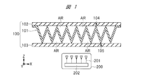
- FIG. 3 is a cross-sectional view showing the radome of the first embodiment, and is a schematic view showing the relationship between the radome and the radar.
- FIG. 3 is a perspective view showing a resin film according to the first embodiment.
- FIG. 3 is a perspective view showing a resin film according to the first embodiment.
- FIG. 3 is a perspective view showing a resin film according to the first embodiment.
- FIG. 6 is a plan view showing a resin film according to a second embodiment. It is sectional drawing which shows the radome of Embodiment 2, and is a schematic diagram which shows the relationship between a radome and a radar. It is sectional drawing which shows the radome of the modification 1, and is a schematic diagram which shows the relationship between a radome and a radar.
- FIG. 1 is a cross-sectional view showing a radome 100 according to this embodiment, and is a schematic view showing a relationship between the radome 100 and a radar 200.
- the radome 100 constitutes the whole or a part of a bumper attached to the front of the automobile, and the radar 200 mounted inside the automobile is covered by the radome 100.
- the Z direction shown in the figure is the thickness direction of the radome 100, and the direction from the back film 103 to the front film 102 is the front direction of the automobile.
- the X direction is the side direction of the automobile and the Y direction is the height direction of the automobile. These X direction, Y direction and Z direction are orthogonal to each other.
- the radome 100 includes a resin film 101 having a front surface and a back surface, a surface film 102 formed on the front surface side of the resin film 101, and a back film 103 formed on the back surface side of the resin film 101.
- a resin film 101 having a front surface and a back surface
- a surface film 102 formed on the front surface side of the resin film 101
- a back film 103 formed on the back surface side of the resin film 101.
- the front surface side of the resin film 101 is the outside of the automobile
- the back surface side of the resin film 101 is the inside of the automobile.
- a radar 200 is mounted inside the vehicle.
- the radar 200 is a millimeter wave radar and has a plurality of antennas 201 and an RF circuit (high frequency circuit) 202 electrically connected to the plurality of antennas 201.
- the plurality of antennas 201 are provided in an array and include transmitting and receiving antennas.
- the RF circuit 202 generates a millimeter wave signal inside, and the millimeter wave signal is radiated from the antenna 201 for transmission to the outside of the automobile via the radome 100.
- the radiated millimeter wave signal reaches the target, and the millimeter wave signal reflected (scattered) by the target is received by the receiving antenna 201 via the radome 100.
- the wavelength is, for example, 3 mm
- the frequency is, for example, 77 GHz band or 79 GHz band.
- the resin film 101 is made of synthetic resin, for example, polypropylene or polystyrene, and has a thickness of, for example, 30 to 50 ⁇ m.
- the dielectric constant of the resin film 101 is 3.0, for example.
- the resin film 101 of the present embodiment has a corrugated board structure and has an uneven shape. That is, the resin film 101 has a shape in which a concave portion projecting to the back surface side of the resin film 101 and a convex portion projecting to the front surface side of the resin film 101 are alternately repeated. Further, the resin film 101 is formed such that its surface is inclined with respect to the traveling direction of the radio wave transmitted through the inside of the radome 100.
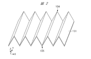
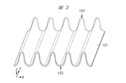
- FIGS 2 to 4 are perspective views each showing an example of the shape of the resin film 101.
- the resin film 101 has a structure forming a one-dimensional triangular waveform, and includes a triangle formed by the resin film 101 and the front surface film 102 and a triangle formed by the resin film 101 and the back surface film 103.
- it is a so-called truss structure, which is a structure that is continuously connected. That is, in cross-sectional view, the shape of the resin film 101 between the apex 105 of the concave portion and the apex 104 of the convex portion is linear.
- the resin film 101 has a structure that forms a one-dimensional sine waveform. That is, in cross-sectional view, the shape of the resin film 101 between the apex 105 of the concave portion and the apex 104 of the convex portion is curved.
- the structure of FIG. 2 has high strength against pressure from a direction perpendicular to the surface of the radome 100 (the front surface of the automobile).
- the structure of FIG. 3 has high strength against pressure from a direction perpendicular to the surface of the radome 100, and is higher than the structure of FIG. 2 against pressure from a direction oblique to the surface of the radome 100. Have strength.
- the resin film 101 between the apex 105 of the concave portion and the apex 104 of the convex portion has a curved shape in a cross-sectional view, but the resin film 101 has a two-dimensional shape. It has a structure that forms the waveform of a typical trigonometric function.
- Such a structure of FIG. 4 has higher strength than the structures of FIGS. 2 and 3 against pressure from directions perpendicular to the surface of the radome 100 and oblique directions.
- the resin film 101 having the concave portion and the convex portion preferably has the shape shown in FIGS. 2 to 4. It only has to have an oblique shape.
- the shapes of the concave portion and the convex portion may be pyramidal, conical, hemispherical, or semielliptic, respectively. Further, these shapes may be applied to all or a part of the plurality of concave portions and the plurality of convex portions.
- the period of the wave composed of the triangular waveform or the sine waveform is set to be less than the wavelength of the millimeter wave transmitted through the radome 100. That is, the cycle in which the pair of concave and convex portions is formed is less than the wavelength of the millimeter wave transmitted through the radome 100.
- the resin film 101 is bonded to the front surface film 102 and the back surface film 103. Specifically, the resin film 101 is adhered to the front surface film 102 at the apex 104 of the convex portion and adhered to the back surface film 103 at the apex 105 of the concave portion. Therefore, a desired substance can be present between the resin film 101 and the front surface film 102 and between the resin film 101 and the back surface film 103. In the present embodiment, air AIR is exemplified as such a substance.
- a resin film is preferably used for each of the front surface film 102 and the rear surface film 103 as a material having solvent resistance to a water-based or oil-based coating material and environment resistance.
- each of the front surface film 102 and the back surface film 103 is made of a plate-shaped synthetic resin, for example, polyphenylene sulfide (PPS).
- Each of the front surface film 102 and the rear surface film 103 is formed of a resin material having a higher dielectric constant and higher hardness than the resin film 101 in order to improve mechanical strength.
- each of the front surface film 102 and the back surface film 103 is sufficiently smaller than the wavelength used in the radar 200 and is a thickness that allows millimeter waves to pass therethrough, for example, 50 to 100 ⁇ m. Therefore, it is possible to ensure the transparency of the millimeter wave that passes through the radome 100.
- the thickness of the region where the uneven resin film 101 and the air AIR are present, that is, the distance between the front surface film 102 and the back surface film 103 is, for example, 3 to 5 mm.
- air AIR having a lower dielectric constant than resin film 101 exists between resin film 101 and front surface film 102 and between resin film 101 and rear surface film 103. There is. Air AIR has a dielectric constant of 1.0.
- the resin film 101 is also formed inside the radome 100, since the resin film 101 is thin and is made of a material having a low dielectric constant, the equivalent dielectric constant in the entire radome 100 can be kept low. In other words, since the dielectric constant averaged by the air AIR and the resin film 101 can be regarded as an equivalent dielectric constant, in the radome 100 of the present embodiment, the radome 100 is composed of the resin film 101. Also, the dielectric constant can be lowered.
- the permittivity inside the radome 100 can be made closer to the permittivity outside the radome 100 (permittivity of air). Further, the thickness of each of the front surface film 102 and the back surface film 103 is such that millimeter waves can be transmitted. Therefore, when the millimeter wave reflected from the target outside the vehicle passes through the inside of the radome 100, the millimeter wave is received by the radar 200 without being substantially attenuated.
- the resin film 101 is formed in an uneven shape inside the radome 100, and the surface of the resin film 101 is inclined with respect to the traveling direction of the radio wave that passes through the inside of the radome 100. Further, in the concavo-convex shape, the cycle in which the pair of concave and convex portions is formed is less than the wavelength of the millimeter wave transmitted through the radome 100.
- the millimeter wave passes through the resin film 101 and the air AIR inside the radome 100.
- the dielectric constant inside the radome 100 is gently changed by the resin film 101 and the air AIR, so that reflection and refraction of millimeter waves can be suppressed. That is, inside the radome 100, it is difficult for mirror reflection of millimeter waves to occur.
- the characteristic impedance of the radome 100 can be changed stepwise from the surface film 102 side to the inside of the radome 100, so that the characteristics of the inside of the radome 100 and the air AIR outside the radome 100. The impedance ratio is minimized.
- the uneven resin film 101 may be formed of a foamed resin film.
- the dielectric constant of the resin film 101 itself can be further reduced, the equivalent dielectric constant inside the radome 100 can be further reduced.
- the radome 100 of the present embodiment is provided so as to sufficiently cover the radiation range of the antenna 201, it becomes possible to suppress the reflection intensity of millimeter waves. As a result, multipath due to irregular reflection is reduced, erroneous detection of the radar 200 is suppressed, and the detection accuracy of the radar 200 can be improved.
- the uneven resin film 101 formed between the front surface film 102 and the rear surface film 103 serves as a pillar. Therefore, the mechanical strength of the radome 100 itself can be improved. That is, the radome 100 of the present embodiment can improve the mechanical strength of the radome 100 to such an extent that the radome 100 can withstand a use environment such as an automobile without lowering the detection accuracy of the radar 200.
- the performance of the radome 100 that covers the radar 200 can be improved.
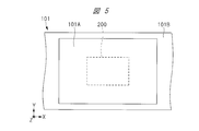
- FIG. 5 is a plan view of the resin film 101 according to the second embodiment, which is a plan view parallel to the XY plane. In the following description, differences from the first embodiment will be mainly described.
- the entire resin film 101 has an uneven shape inside the radome 100, but in the second embodiment, a part of the resin film 101 has an uneven shape.
- the resin film 101 of the second embodiment includes a transparent region 101A and a fixed region 101B integrated with the transparent region 101A.
- the resin film 101 in the transmissive region 101A has an uneven shape as in the first embodiment.
- the resin film 101 in the fixed area 101B is formed thicker than the resin film 101 in the transmissive area 101A so as to fill the space between the front surface film 102 and the back surface film 103.
- Such a resin film 101 can be manufactured by changing the shape of the mold.
- the front surface film 102 adheres to the front surface of each resin film 101 in the transmissive area 101A and the fixed area 101B, and the back surface film 103 adheres to the rear surface of each resin film 101 in the transmissive area 101A and the fixed area 101B.
- the front surface film 102 and the back surface film 103 are formed so as to sandwich the resin film 101 in each of the transmissive region 101A and the fixed region 101B.
- the transmission region 101A is provided only in the region where the millimeter wave is desired to be transmitted, according to the range of the angle detection of the radar 200.
- the radar 200 is arranged so as to overlap the transmission area 101A and to be included in the transmission area 101A in a plan view (front view of the vehicle).
- the detection accuracy of the radar 200 can be improved.
- the mechanical strength of the radome 100 as a whole can be further improved by increasing the thickness of the resin film 101.
- the front surface film 102 and the rear surface film 103 are formed only in the transmissive area 101A and not in the fixed area 101B. That is, the front surface and the back surface of the resin film 101 in the fixed region 101B are exposed from the front film 102 and the back film 103, respectively.
- the radome 100 does not constitute the entire bumper of the automobile, but is a member attached to the base material 106 which is the bumper, and constitutes a part of the bumper. There is.
- the radome 100 can be mounted on the base material 106 by providing, for example, an adhesive in the gap between the radome 100 and the base material 106.
- the radar 200 is The radome 100 can be selectively attached to the place where it is arranged. Therefore, the degree of freedom in designing the bumper can be increased. Further, since the radome 100 of the modified example 2 is a structure having a size corresponding to the above-mentioned transmission area 101A, the detection accuracy of the radar 200 does not deteriorate as compared with the other embodiments.
- the radome 100 and the base material 106 can be manufactured separately. Therefore, for example, the bumper, which is the base material 106, is manufactured on a manufacturing line of a predetermined factory, the radome 100 is manufactured on another manufacturing line or another factory, and they are finally combined to complete the bumper. You can also
- Modification 2 as in Modification 1, only the portion corresponding to the transmissive region 101A is partially heated to bond the front surface film 102 and the back surface film 103 to the radome 100, thus improving the bonding accuracy. Therefore, it is possible to suppress the manufacturing cost associated with the film itself and the film adhesion.
- a coating film 107 made of a material different from that of the surface film 102 is formed on the surface of the surface film 102 having solvent resistance.
- a liquid obtained by diluting a base coat, which is a mixture of an aqueous or oily coating material and a curing agent, with thinner is used, and the coating film 107 is obtained by drying the liquid.
- the coating film 107 may be formed by a printing technique. Further, even when a material such as a paint contains a metal such as indium, the thickness of the coating film 107 is set to 1/10 or less of the skin effect thickness (the conductor resistivity is 1 ⁇ or more). To do.
- the thickness of the coating film 107 is sufficiently thinner than the wavelength used in the radar 200 and is a thickness that allows millimeter waves to pass through, and is, for example, 50 ⁇ m.
- the total thickness of the coating film 107 and the surface film 102 is also a thickness that allows millimeter waves to pass therethrough.
- the foamed resin film FP1 is filled between the resin film 101 and the surface film 102.
- the foamed resin film FP1 has a higher foaming rate than the resin film 101 and has a foaming rate of about 50 to 800%.
- the dielectric constant of the foamed resin film FP1 is lower than the dielectric constant of the resin film 101, and is, for example, 1.05 to 2.4. That is, the dielectric constant of the foamed resin film FP1 is about 2.4 when the foaming rate is 50%, and about 1.05 when the foaming rate is 800%.
- the substance existing between the resin film 101 and the surface film 102 is air AIR having a dielectric constant of 1.0.
- the foamed resin film FP1 is used instead of the air AIR. Has been applied. Therefore, the equivalent dielectric constant inside the radome 100 of the fourth embodiment is slightly higher than that of the first embodiment.
- the mechanical strength of the radome 100 can be improved by applying the foamed resin film FP1 having a hardness higher than that of the air AIR and adhering the foamed resin film FP1 to the surface film 102. .
- the surface film 102 may bend, the shape formed by the resin film 101 and the surface film 102 may change, and the equivalent dielectric constant may change.
- a strong pressure is applied to the surface film 102 due to the wind pressure received by the automobile while the automobile is running.
- the characteristic impedance inside the radome 100 may change, and the wavelength received by the radar 200 may shift. Therefore, by filling the space between the resin film 101 and the surface film 102 with a substance having higher mechanical strength than the air AIR, such as the foamed resin film FP1, the possibility that the surface film 102 will bend is reduced, and Such a fear can be suppressed.
- a substance having higher mechanical strength than the air AIR such as the foamed resin film FP1
- a hole 108 penetrating the back film 103 is formed in a part of the back film 103, and a hole 109 penetrating the resin film 101 is formed in a part of the resin film 101. Are formed.
- the air AIR exists inside the radome 100 according to the fifth embodiment, but the air AIR inside the radome 100 expands or contracts when the temperature changes due to, for example, changes in the weather. For example, when the temperature decreases, the air contracts and the pressure inside the radome 100 decreases. Further, when the temperature rises, the air expands and the pressure inside the radome 100 increases. Then, inside the radome 100, a deviation may occur with respect to the thickness of the air AIR, the equivalent dielectric constant may change, and the characteristic impedance may change.
- the pressure outside the radome 100 and the pressure inside the radome 100 can be made substantially the same. Therefore, the above fear can be suppressed.
- each of the holes 108 and 109 may be such that air can enter, and is larger than, for example, nitrogen molecules (N 2 ) and oxygen molecules (O 2 ). Further, it is desirable that these sizes are such that a liquid cannot penetrate, and it is desirable that they are smaller than water molecules (H 2 O), for example.
- the case where one hole 108 and one hole 109 are provided is illustrated, but a plurality of holes 108 may be provided in the back film 103 and a plurality of holes 109 may be provided in the resin film 101. Further, in the region where the millimeter wave is transmitted, it is desirable that the equivalence of the millimeter wave is as uniform as possible at each place. Therefore, it is preferable that the holes 108 and 109 are provided at the places where the millimeter wave is not transmitted. .
- the foamed resin film FP1 described in the fourth embodiment is filled between the resin film 101 and the front surface film 102, and the back surface film 103 is formed in the fifth embodiment.
- the holes 108 described are provided. Therefore, in Modification 3, the foamed resin film FP1 can be applied to improve the mechanical strength of the radome 100. Further, by applying the holes 108, the pressure outside the radome 100 and the radome 100 can be improved. The pressure inside 100 can be about the same.
- the resin film 101 having an uneven shape was formed inside the radome 100, but in Embodiment 6, between the front surface film 102 and the back surface film 103, It is filled with the foamed resin film FP2.
- the foamed resin film FP2 is a resin film similar to the foamed resin film FP1, has a higher foaming rate than the resin film 101, and has a foaming rate of about 50 to 800%. Further, the dielectric constant of the foamed resin film FP1 is lower than the dielectric constant of the resin film 101, and is, for example, 1.05 to 2.4.
- the foaming rate of the foamed resin film FP2 is not uniform and varies in the thickness direction (Z direction), and the foamed resin film FP2 goes from the front film 102 and the back film 103 toward the center of the foamed resin film FP2. And then gradually (continuously) lower. That is, the dielectric constant of the foamed resin film FP2 gradually (continuously) decreases from the center of the foamed resin film FP2 toward the front surface film 102 and the back surface film 103, respectively.
- the foamed resin film FP2 in the thickness direction (Z direction) of the foamed resin film FP2, the foamed resin film FP2 has a first region closer to the center of the foamed resin film FP2, a second region closer to the surface film 102 than the first region, and , And has a third region closer to the back film 103 than the first region. Then, the foaming rate of the foamed resin film FP2 in the second area and the third area is higher than the foaming rate of the foamed resin film FP2 in the first area, and the dielectric constant of the foamed resin film FP2 in the second area and the third area is , Lower than the dielectric constant of the foamed resin film FP2 in the first region.
- the front surface film 102 and the back surface film 103 are partially bonded to the foamed resin film FP2 at locations other than bubbles in the foamed resin film FP2. Therefore, an adhesive for bonding the front surface film 102 and the rear surface film 103 to the foamed resin film FP2 is not necessary, and an increase in the dielectric constant inside the radome 100 can be suppressed.
- the foamed resin film FP2 Since the resin film forming the foamed resin film FP2 has a high foaming rate, the foamed resin film FP2 has many gaps, is mechanically fragile, and has a drawback of adsorbing or absorbing various gases. Have. However, as in the sixth embodiment, the front surface film 102 and the rear surface film 103 having solvent resistance to a water-based or oil-based coating material and high environmental resistance are formed on the front surface and the back surface of the foamed resin film FP2. By doing so, such a defect can be compensated.
- the equivalent dielectric constant inside the radome 100 is higher than that in the first embodiment.
- the mechanical strength of the radome 100 can be improved as compared with the first embodiment.
- the coating film 107 described in the third embodiment can be formed on the surface film 102 of the sixth embodiment.
- the entire radome 100 is curved. Specifically, the radome 100 is curved so as to warp in the direction from the back film 103 to the front film 102.
- the radome 100 of FIG. 1 is prepared, and then the radome 100 is appropriately softened until the resin film 101, the front surface film 102, and the back surface film 103 are softened. This can be achieved by heating 100 and then subjecting the radome 100 to curved processing by press molding.
- the resin film 101 is formed into a concavo-convex shape so that the entire resin film 101 has a curved shape, and then to bond the front surface film 102 and the back surface film 103 to the resin film 101, it is actually difficult. Is. As in the seventh embodiment, after the front surface film 102 and the back surface film 103 are bonded to the uneven resin film 101, the entire radome 100 is curved using press molding, so that the radome 100 with high processing accuracy is obtained. Can be formed.
- the curved radome 100 can meet various vehicle design requirements.
- the radome 100 is a bumper attached to the front of the automobile has been described, but the radome 100 may be applied to a bumper attached to the rear or side of the automobile.
- the radome 100 covering the radar 200 is mainly used for an automobile.
- a radome 100 is used for another vehicle such as a railroad, an aircraft or a ship. You can also
Landscapes
- Engineering & Computer Science (AREA)
- Radar, Positioning & Navigation (AREA)
- Remote Sensing (AREA)
- Physics & Mathematics (AREA)
- Computer Networks & Wireless Communication (AREA)
- General Physics & Mathematics (AREA)
- Electromagnetism (AREA)
- Details Of Aerials (AREA)
- Variable-Direction Aerials And Aerial Arrays (AREA)
- Radar Systems Or Details Thereof (AREA)
Abstract
レーダなどを覆うレドームの性能を向上させる。レーダ200を覆うレドーム100は、表面および裏面を有する樹脂膜101と、樹脂膜101の表面側に形成された表面フィルム102と、樹脂膜101の裏面側に形成された裏面フィルム103と、を有する。ここで、樹脂膜101は、例えば凹凸形状を成している。また、表面フィルム102と樹脂膜101との間に存在する物質の誘電率、および、裏面フィルム103と樹脂膜101との間に存在する物質の誘電率は、それぞれ樹脂膜101の誘電率よりも低くなっている。これらの物質は、例えば空気AIRである。
Description
本発明は、レドームに関し、特に、自動車などに搭載されたミリ波レーダを覆うレドームに関する。
自動車、鉄道、航空機または船舶などの乗り物において、安全運行または安全動作のための周辺検知センサとして、電波を用いたドップラーセンサまたはレーダセンサなどが知られている。以下では説明の簡略化のため、乗り物の例として、主に自動車について説明する。
自動車用のレーダには、安全運転の支援および自動運転などの実現に向けて、自動車の全周囲を検知するため、検知距離および検知角度の範囲が異なる複数のレーダが用いられている。特に、自動車の前方用であり、且つ、遠距離向けのレーダでは、時速制限の無いアウトバーンなどを時速200km/hで走行した場合においても、自動車が安全に停止できるように、最大検知距離が200m以上であることが望まれている。そのようなレーダのアンテナでは、水平方位の検知範囲を±8deg以上とし、且つ、垂直方位のアンテナ半値幅を±2deg以下とした狭角ビームを適用することで、アンテナの高利得特性が得られている。
また、自動車が稼働する時間の大部分は、市街地における走行に費やされる。そのため、高利得のアンテナが採用される遠距離向けのレーダにおいても、交差点での右折時若しくは左折時、または、横断歩道での通過時に、道路状況に応じた車両周囲の障害物の検知が望まれている。そのような要求として、例えば±30deg以上の広角検知が望まれている。
±8deg程度の範囲の角度検知であれば、レーダを覆う樹脂膜であるレドームの厚さをλ/2の整数倍に設計し、定在波を利用することで、互いに誘電率の異なる空気と樹脂膜との境界面においても、電波透過特性の劣化を最小限に抑えることが可能である。
しかしながら、ミリ波帯の電波を扱うミリ波レーダにおいて、±30deg以上の範囲の角度検知を実現するためには、透過方向におけるレドームの厚さをλ/2の整数倍に設計する必要があるので、アンテナの放射源を中心とした曲面状のレドームが必要となる。また、複数のアンテナから構成されるアンテナアレイを有するミリ波レーダでは、複数の放射源からの距離が、互いに同じになるような曲面状のレドームが必要になるが、そのようなレドームの厚さのばらつきを抑えることは非常に困難である。
更に、レーダをバンパなどの裏面側に配置した場合、バンパのうち電波が透過する部分にのみ、局所的に曲面状のレドームを適用したデザインは、車両の意匠性の観点からあまり望まれていない。
例えば、以下の各特許文献に示されるように、互いに誘電率の異なる空気と樹脂膜との境界における反射作用を抑制するため、様々な技術が検討されている。
特許文献1には、物理的法則を用いる技術が開示されており、ミリ波レーダの電波の放射方向に樹脂膜からなるバンパを設置する際、樹脂膜への電波の入射角度をブルースター角と一致させたバンパ構造が開示されている。
特許文献2には、樹脂膜からなるバンパにレーダを直接搭載させる技術が開示されており、バンパとミリ波レーダとを、ホーン形状のブラケットを用いて接続し、ホーンアンテナの開口径に応じた穴をバンパに設けた構造が開示されている。
特許文献3には、樹脂膜からなるバンパの一部を、凹凸形状の山として加工することで、反射を抑圧する技術が開示されている。
特許文献1に開示されたバンパは、アンテナの広角度の放射範囲の一部のみをブルースター角度に一致させることで、反射強度を最小に抑制することが可能である。しかしながら、広角の検知角度の大部分は反射を抑制することができないという問題がある。
特許文献2に開示されたバンパは、バンパに穴を開けることで、電波の伝播経路において、不要な反射を低減することができる。しかしながら、テーパー状のホーン内部では電波の波面が平面化されるため、広角度方位へのアンテナ利得は低く、広角度の検知には不向きである。また、バンパに穴が存在するため、車両走行時におけるゴミ若しくは埃などの異物の混入、または、降雨時における水滴の混入が発生する恐れがあり、これらの問題によってアンテナ特性が劣化する。
特許文献3に開示されたバンパでは、レーダ側のバンパの表面に、ピラミッド形状の複数の凹凸部(被覆部品)をアレイ状に設け、凹凸部まで土台の高さを波長の1/4の奇数倍としている。ピラミッド形状を採用することによって、レーダ装置から放射された電波は、凹凸部を透過し、バンパの内部まで達する。しかしながら、その電波は、バンパの誘電率と空気の誘電率との差によって生じる臨界角において、鏡面反射する。レーダ装置の角度検知の範囲が臨界角の範囲内であれば、反射強度は小さいが、例えば、誘電率が4程度の樹脂膜(屈折率2程度)では、臨界角は45度となり、それ以上の角度方位では透過電力が減少するため、レーダ装置の感度が低下する。
また、ピラミッド形状の凹凸部をバンパの表面に設けた場合、自動車が通常に使用される環境では、バンパの表面に泥、水および汚れなどが付着するため、良好なミリ波の透過特性を保つことが難しい。更に、バンパの表面の凹凸部がむき出しである状態で、バンパの表面に塗装を施した場合、凹凸部の凹部に塗料が埋め込まれるため、ピラミッド形状の機能を保つことができない。また、バンパの表面に凹凸部を設けることは、車両の意匠性の観点においても実用性に乏しい。
本願発明者らは、バンパの表面における反射強度の抑制という観点から、樹脂膜の誘電率の低減を考察した。近年、自動車、鉄道、航空機または船舶などの乗り物において、電動化および低燃費化が進行している。例えば、自動車では、低燃費化の一環として車体の軽量化が取り組まれ、軽量化のために、バンパの材料となる樹脂膜の発泡化が検討されている。そして、樹脂膜の発泡化を進めることで、樹脂膜の低誘電率化も促進されている。
また、塗装の観点から、バンパの表面側では、硬さおよび滑らかさが求められるため、発泡樹脂膜の気泡が少なくなっている。そして、バンパの内部では、発泡樹脂膜の気泡が多く含まれている。すなわち、バンパを構成する発泡樹脂膜の誘電率は、バンパの表面において大きく、バンパの内部において小さい。また、発泡樹脂膜を用いたバンパは、機械的強度にも着目しているため、発泡樹脂膜の発泡率は50%程度であり、発泡樹脂膜の誘電率は2.4程度である。このような値は、バンパの表面における反射を抑制するために、十分に小さい値ではない。
上述のように、ミリ波レーダのアンテナは、アンテナ外の環境による影響を受けやすいため、アンテナは、電波を透過しやすい樹脂膜のレドームまたはバンパによって、機械的および環境的に保護されている。そして、自動車用のミリ波レーダに用いるアンテナには、それが遠距離向けのレーダ用のアンテナであったとしても、水平方位の半値幅を±30deg~±60degとした広角検知性能が求められている。
また、アンテナが広角度の放射範囲を有していても、アンテナを保護するレドームの表面における反射によって透過電力が減衰すると、アンテナの広角度の放射特性が犠牲となり、アンテナの感度が低下し、反射電力がマルチパスとしてアンテナに再入力される。その結果、レーダ検知における妨害雑音が発生する。
従って、レーダを覆うレドームなどには、反射強度が抑制されるように、レドームと、レドームの外部の空気との接触面における誘電率の差を低下させる必要がある。そのため、レドームには、レドームを構成する材料の低誘電化、および、利用環境に耐えることができる機械強度を両立する構造が求められている。すなわち、レーダなどを覆うレドームのような被覆部材の性能の向上が求められている。
その他の課題と新規な特徴は、本明細書の記述および添付図面から明らかになるであろう。
本願において開示される実施の形態のうち、代表的なものの概要を簡単に説明すれば、次のとおりである。
一実施の形態であるレドームは、表面および裏面を有する樹脂膜と、樹脂膜の表面側に形成された第1フィルムと、樹脂膜の裏面側に形成された第2フィルムとを有する。ここで、第1フィルムと樹脂膜との間に存在する物質の誘電率、および、第2フィルムと樹脂膜との間に存在する物質の誘電率は、それぞれ樹脂膜の誘電率よりも低い。
本願において開示される実施の形態によれば、レーダなどを覆うレドームの性能を向上させることができる。
以下、本発明の実施の形態を図面に基づいて詳細に説明する。なお、実施の形態を説明するための全図において、同一の機能を有する部材には同一の符号を付し、その繰り返しの説明は省略する。また、以下の実施の形態では、特に必要なときを除き、同一または同様な部分の説明を原則として繰り返さない。
(実施の形態1)
本実施の形態では、乗り物である自動車に搭載されたレーダ200と、レーダ200を覆う被覆部材であるレドーム100とについて説明する。図1は、本実施の形態のレドーム100を示す断面図であり、レドーム100とレーダ200との関係を示す概略図である。本実施の形態では、レドーム100が、自動車の前方に取り付けられるバンパの全体または一部を構成し、自動車の内部に搭載されたレーダ200が、レドーム100に覆われている場合を例示する。
本実施の形態では、乗り物である自動車に搭載されたレーダ200と、レーダ200を覆う被覆部材であるレドーム100とについて説明する。図1は、本実施の形態のレドーム100を示す断面図であり、レドーム100とレーダ200との関係を示す概略図である。本実施の形態では、レドーム100が、自動車の前方に取り付けられるバンパの全体または一部を構成し、自動車の内部に搭載されたレーダ200が、レドーム100に覆われている場合を例示する。
なお、図中に示されるZ方向は、レドーム100の厚さ方向であり、裏面フィルム103から表面フィルム102へ向かう方向が、自動車の前方向である。また、X方向は自動車の側方向であり、Y方向は自動車の高さ方向である。これらのX方向、Y方向およびZ方向は、互いに直交している。
図1に示されるように、レドーム100は、表面および裏面を有する樹脂膜101と、 樹脂膜101の表面側に形成された表面フィルム102と、樹脂膜101の裏面側に形成された裏面フィルム103とを有する。樹脂膜101の表面側は自動車の外部側であり、樹脂膜101の裏面側は自動車の内部側である。自動車の内部にはレーダ200が搭載されている。
レーダ200は、ミリ波レーダであり、複数のアンテナ201、および、複数のアンテナ201に電気的に接続されたRF回路(高周波回路)202を有する。複数のアンテナ201は、アレイ状に設けられ、送信用および受信用のアンテナを含む。
RF回路202は、その内部でミリ波信号を生成し、ミリ波信号は、レドーム100を介して、送信用のアンテナ201から自動車の外部へ放射される。放射されたミリ波信号は、ターゲットに到達し、ターゲットで反射(散乱)したミリ波信号は、レドーム100を介して、受信用のアンテナ201で受信される。なお、本実施の形態のレーダ200で扱うミリ波信号において、波長は、例えば3mmであり、周波数は、例えば77GHz帯または79GHz帯である。
以下に、本実施の形態のレドーム100の構造について、詳細に説明する。
樹脂膜101は、合成樹脂からなり、例えばポリプロピレンまたはポリスチレンからなり、例えば30~50μmの厚さを有する。樹脂膜101の誘電率は、例えば3.0である。また、本実施の形態の樹脂膜101は、段ボール構造であり、凹凸形状を成している。すなわち、樹脂膜101は、樹脂膜101の裏面側に突出する凹部、および、樹脂膜101の表面側に突出する凸部が交互に繰り返される形状を成している。また、樹脂膜101は、レドーム100の内部を透過する電波の進行方向に対して、その表面が斜めになるように形成されている。
図2~図4は、それぞれ樹脂膜101の形状例を示す斜視図である。
図2では、樹脂膜101は、一次元的な三角波形を成す構造となっており、樹脂膜101および表面フィルム102で構成される三角形と、樹脂膜101および裏面フィルム103で構成される三角形とが、連続的に繋がった構造となっており、所謂トラス構造となっている。すなわち、断面視において、凹部の頂点105と凸部の頂点104との間の樹脂膜101の形状は、直線状となっている。
図3では、樹脂膜101は、一次元的なサイン波形を成す構造となっている。すなわち、断面視において、凹部の頂点105と凸部の頂点104との間の樹脂膜101の形状は、曲線状となっている。図2の構造は、レドーム100の表面(自動車の前面)に垂直な方向からの圧力に対して、高い強度を有する。図3の構造は、レドーム100の表面に垂直な方向からの圧力に対して、高い強度を有し、更に、レドーム100の表面に斜めな方向からの圧力に対して、図2の構造より高い強度を有する。
図4では、図3と同様に、断面視において、凹部の頂点105と凸部の頂点104との間の樹脂膜101の形状は、曲線状となっているが、樹脂膜101は、二次元的な三角関数の波形を成す構造となっている。このような図4の構造は、レドーム100の表面に垂直および斜めな方向からの圧力に対して、図2および図3の構造よりも、高い強度を有する。
このように、凹部および凸部を有する樹脂膜101は、図2~図4の形状を成していることが好ましいが、レドーム100の内部を透過する電波の進行方向に対して、その表面が斜めになるような形状を成していればよい。例えば、凹部および凸部の形状を、それぞれピラミッド形状、円錐状、半球状または半楕円球状などとすることも可能である。また、これらの形状を、複数の凹部および複数の凸部のうち、全部に適用してもよいし、一部のみに適用してもよい。
また、上記の凹凸形状において、三角波形またはサイン波形からなる波の周期は、レドーム100を透過するミリ波の波長未満に設定されている。すなわち、一組の凹部および凸部が形成される周期は、レドーム100を透過するミリ波の波長未満である。
樹脂膜101は、表面フィルム102および裏面フィルム103に接着している。具体的には、樹脂膜101は、凸部の頂点104において表面フィルム102に接着し、凹部の頂点105において裏面フィルム103に接着している。このため、樹脂膜101と表面フィルム102との間、および、樹脂膜101と裏面フィルム103との間に、所望の物質を存在させることができる。本実施の形態では、そのような物質として、空気AIRを例示している。
表面フィルム102および裏面フィルム103の各々には、水性または油性の塗料に対する耐溶剤性を有し、且つ、耐環境性を有する材料として、樹脂膜を使用することが好ましい。本実施の形態では、表面フィルム102および裏面フィルム103の各々は、板状の合成樹脂からなり、例えばポリフェニレンサルファイド(PPS)からなる。
表面フィルム102および裏面フィルム103の各々は、機械的強度を向上させるため、樹脂膜101よりも高い誘電率を有し、且つ、高い硬度を有する樹脂材料によって形成されている。
また、表面フィルム102および裏面フィルム103の各々の厚さは、レーダ200で使用される波長よりも十分に薄く、ミリ波が透過できる厚さであり、例えば50~100μmである。このため、レドーム100内を通過するミリ波の透過性を確保することができる。また、凹凸形状の樹脂膜101と空気AIRとが存在している領域の厚さ、すなわち、表面フィルム102と裏面フィルム103との間の距離は、例えば3~5mmである。
<本実施の形態の主な特徴>
以下に、本実施の形態のレドーム100の主な特徴を記す。
以下に、本実施の形態のレドーム100の主な特徴を記す。
本実施の形態のレドーム100では、樹脂膜101と表面フィルム102との間、および、樹脂膜101と裏面フィルム103との間に、樹脂膜101よりも低い誘電率を有する空気AIRが存在している。空気AIRの誘電率は1.0である。レドーム100の内部には樹脂膜101も形成されているが、樹脂膜101は薄く、低誘電率の材料から構成されているので、レドーム100の内部全体における等価誘電率を低く保つことができる。言い換えれば、空気AIRおよび樹脂膜101によって平均化された誘電率を等価誘電率として見做すことができるので、本実施の形態のレドーム100では、レドーム100を全て樹脂膜101で構成した場合よりも、誘電率を低下させることができる。
すなわち、レドーム100の内部の誘電率を、レドーム100の外部の誘電率(空気の誘電率)に近づけることができる。また、表面フィルム102および裏面フィルム103の各々の厚さは、ミリ波が透過できる厚さである。このため、自動車の外部のターゲットから反射したミリ波が、レドーム100の内部を透過する際、ミリ波は、ほぼ減衰することなくレーダ200にて受信される。
また、レドーム100の内部において、樹脂膜101が凹凸形状で形成されており、レドーム100の内部を透過する電波の進行方向に対して、樹脂膜101の表面は斜めになっている。また、凹凸形状において、一組の凹部および凸部が形成される周期は、レドーム100を透過するミリ波の波長未満である。
このため、ミリ波は、レドーム100の内部において、樹脂膜101および空気AIRを透過する。ミリ波の進行方向において、レドーム100の内部では、樹脂膜101および空気AIRによって誘電率が緩やかに変化しているため、ミリ波の反射および屈折を抑制することができる。すなわち、レドーム100の内部において、ミリ波の鏡面反射が発生し難くなっている。結果として、レドーム100の特性インピーダンスを、表面フィルム102側からレドーム100の内部へかけて、段階的に変化させることができるので、レドーム100の内部と、レドーム100の外部である空気AIRとの特性インピーダンス比は最小化される。
なお、凹凸形状の樹脂膜101は、発泡樹脂膜によって形成されていてもよい。この場合、樹脂膜101自体の誘電率を更に低下させることができるので、レドーム100の内部の等価誘電率を、更に低下させることができる。
アンテナ201の放射範囲を十分にカバーするように、本実施の形態のレドーム100を設ければ、ミリ波の反射強度を抑制することが可能となる。その結果、乱反射によるマルチパスが低減され、レーダ200の誤検知が抑制され、レーダ200の検知精度を向上させることができる。
更に、本実施の形態のレドーム100では、表面フィルム102と裏面フィルム103との間に形成されている凹凸形状の樹脂膜101が、支柱の役割を果たす。従って、レドーム100自体の機械的強度を向上させることができる。すなわち、本実施の形態のレドーム100によって、レーダ200の検知精度を低下させることなく、自動車などにおける利用環境に耐えられる程度に、レドーム100の機械的強度を向上させることができる。
また、仮に、表面フィルム102を設けず、樹脂膜101をむき出しにした場合、樹脂膜101の凹部に、泥、水および汚れなどの異物が堆積する恐れがある。このような異物がレドーム100に付着すると、レドーム100の表面付近において、ミリ波が反射するまたは減衰するなどの不具合が発生し易くなる。本実施の形態では、凹凸形状の樹脂膜101の表面側に、平坦な表面を有する表面を有し、且つ、ミリ波が透過できる厚さを有するフィルム102が形成されているので、そのような不具合を解消することができる。
以上のように、本実施の形態によれば、レーダ200を覆うレドーム100の性能を向上させることができる。
(実施の形態2)
以下に、実施の形態2のレドーム100を、図5および図6を用いて説明する。図5は、実施の形態2の樹脂膜101の平面図であり、X-Y面に平行な平面図である。なお、以下の説明では、実施の形態1との相違点を主に説明する。
以下に、実施の形態2のレドーム100を、図5および図6を用いて説明する。図5は、実施の形態2の樹脂膜101の平面図であり、X-Y面に平行な平面図である。なお、以下の説明では、実施の形態1との相違点を主に説明する。
実施の形態1では、レドーム100の内部において、樹脂膜101全体が凹凸形状であったが、実施の形態2では、樹脂膜101の一部が凹凸形状である。
図5および図6に示されるように、実施の形態2の樹脂膜101は、透過領域101A、および、透過領域101Aと一体化している固定領域101Bを含む。透過領域101Aの樹脂膜101は、実施の形態1と同様に、凹凸形状を成している。固定領域101Bの樹脂膜101は、表面フィルム102と裏面フィルム103との間を充填するように、透過領域101Aの樹脂膜101の厚さよりも厚く形成されている。このような樹脂膜101は、鋳型の形状を変更することで製造できる。
表面フィルム102は、透過領域101Aおよび固定領域101Bにおいて、各々の樹脂膜101の表面に接着し、裏面フィルム103は、透過領域101Aおよび固定領域101Bにおいて、各々の樹脂膜101の裏面に接着している。言い換えれば、表面フィルム102および裏面フィルム103は、透過領域101Aおよび固定領域101Bの各々の樹脂膜101を挟み込むように形成されている。
実施の形態2では、レドーム100の内部において、レーダ200の角度検知の範囲に合わせて、ミリ波を透過させたい領域のみに透過領域101Aを設けている。言い換えれば、平面視(自動車の前面視)において、レーダ200は、透過領域101Aに重なるように配置され、透過領域101Aに内包されるように配置されている。この場合も実施の形態1と同様に、レーダ200の検知精度を向上させることができる。また、ミリ波を透過させない固定領域101Bでは、樹脂膜101の厚さを厚くしたことで、レドーム100全体としての機械的強度を更に向上させることができる。
(変形例1)
以下に、実施の形態2の変形例1のレドーム100を、図7を用いて説明する。なお、以下の説明では、実施の形態2との相違点を主に説明する。
以下に、実施の形態2の変形例1のレドーム100を、図7を用いて説明する。なお、以下の説明では、実施の形態2との相違点を主に説明する。
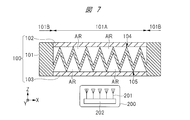
図7に示されるように、変形例1では、表面フィルム102および裏面フィルム103が、透過領域101Aのみに形成され、固定領域101Bには形成されていない。すなわち、固定領域101Bの樹脂膜101の表面および裏面は、それぞれ表面フィルム102および裏面フィルム103から露出している。
このように、変形例1では、表面フィルム102および裏面フィルム103を凹凸形状である透過領域101Aのみに選択的に形成しているので、実施の形態2と比較して、製造コストを抑制することができる。また、レドーム100がバンパ全体として使用される場合、バンパ全体に表面フィルム102および裏面フィルム103を精度良く接着させることは難しく、局所的に接着力の弱い箇所が存在し易くなる問題がある。これに対して、変形例2では、透過領域101Aのみを部分的に加熱して、レドーム100に表面フィルム102および裏面フィルム103を接着させるため、接着精度を向上させることができ、加熱時間の短縮を図ることができる。
(変形例2)
以下に、実施の形態2の変形例2のレドーム100を、図8を用いて説明する。なお、以下の説明では、実施の形態2との相違点を主に説明する。
以下に、実施の形態2の変形例2のレドーム100を、図8を用いて説明する。なお、以下の説明では、実施の形態2との相違点を主に説明する。
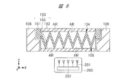
図8に示されるように、変形例2では、レドーム100は、自動車のバンパ全体を構成しておらず、バンパである母材106に取り付けられた部材であり、バンパの一部を構成している。なお、レドーム100と母材106との間の隙間に、例えば接着剤を設けることで、母材106にレドーム100を搭載することができる。
例えば、車両メーカの要求によって、バンパ全体の製造コスト、機械的強度または外観などを考慮し、バンパの主要部が、レドーム100と異なる構造物である母材106によって構成される場合、レーダ200が配置される箇所に、選択的にレドーム100を取り付けることができる。このため、バンパの設計の自由度を高めることができる。また、変形例2のレドーム100は、上述の透過領域101Aに相当する大きさの構造物であるので、他の実施の形態と比較して、レーダ200の検知精度が低下することはない。
また、レドーム100と母材106とをそれぞれ個別に製造することができる。従って、例えば、母材106であるバンパを所定の工場の製造ラインで製造し、レドーム100を他の製造ラインまたは他の工場で製造し、最終的にそれらを組み合わせることで、バンパを完成させることもできる。
また、変形例2では、変形例1と同様に、透過領域101Aに該当する箇所のみを部分的に加熱して、レドーム100に表面フィルム102および裏面フィルム103を接着させるため、接着精度を向上させることができ、フィルム自体およびフィルムの接着に関する製造コストを抑制することができる。
(実施の形態3)
以下に、実施の形態3のレドーム100を、図9を用いて説明する。なお、以下の説明では、実施の形態1との相違点を主に説明する。
以下に、実施の形態3のレドーム100を、図9を用いて説明する。なお、以下の説明では、実施の形態1との相違点を主に説明する。
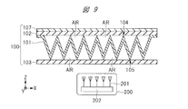
図9に示されるように、実施の形態3では、耐溶剤性を有する表面フィルム102の表面上に、表面フィルム102と異なる材料からなる塗膜107が形成されている。塗膜107の形成には、水性または油性の塗料と、硬化剤とを混合したベースコートをシンナーで希釈した液体が使用され、これを乾燥させることで塗膜107が得られる。また、塗膜107は、印刷技術によって形成されていてもよい。また、塗料などの材料に、例えばインジウムのような金属が含まれる場合においても、塗膜107の厚さが、表皮効果厚さの1/10以下(導体抵抗率が1Ω以上)となるようにする。
塗膜107の厚さは、レーダ200で使用される波長よりも十分に薄く、ミリ波が透過できる厚さであり、例えば50μmである。また、塗膜107の厚さと表面フィルム102の厚さの合計の厚さも、ミリ波が透過できる厚さである。
このような塗膜107を形成することで、レドーム100の外部環境(泥および雨水など)からレドーム100を保護することができ、外観の意匠性を向上させることができる。
なお、実施の形態3で開示した技術を、実施の形態2のレドーム100に適用することもできる。
(実施の形態4)
以下に、実施の形態4のレドーム100を、図10を用いて説明する。なお、以下の説明では、実施の形態1との相違点を主に説明する。
以下に、実施の形態4のレドーム100を、図10を用いて説明する。なお、以下の説明では、実施の形態1との相違点を主に説明する。
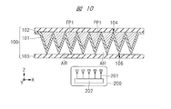
図10に示されるように、実施の形態4では、樹脂膜101と表面フィルム102との間に、発泡樹脂膜FP1が充填されている。発泡樹脂膜FP1は、樹脂膜101よりも高い発泡率を有し、50~800%程度の発泡率を有する。また、発泡樹脂膜FP1の誘電率は、樹脂膜101の誘電率よりも低く、例えば1.05~2.4である。すなわち、発泡樹脂膜FP1の誘電率は、発泡率が50%の場合に2.4程度であり、発泡率が800%の場合に1.05程度である。
実施の形態1では、樹脂膜101と表面フィルム102との間に存在する物質は、誘電率1.0の空気AIRであったが、実施の形態4では、空気AIRに代えて発泡樹脂膜FP1を適用している。このため、実施の形態4のレドーム100内部における等価誘電率は、実施の形態1と比較して若干高くなっている。
しかしながら、実施の形態4では、空気AIRよりも高い硬度を有する発泡樹脂膜FP1を適用し、発泡樹脂膜FP1を表面フィルム102に接着させることで、レドーム100の機械的強度を向上させることができる。
すなわち、レドーム100の外部から圧力が加わると、表面フィルム102がたわみ、樹脂膜101と表面フィルム102とで構成される形状が変化し、等価誘電率が変化する恐れがある。特に、レドーム100を自動車のバンパに適用した場合には、自動車の走行中に自動車が受ける風圧により、表面フィルム102には強い圧力が加えられる。
そのため、レドーム100の内部の特性インピーダンスが変化し、レーダ200で受信する波長がずれる恐れがある。そこで、樹脂膜101と表面フィルム102との間を、発泡樹脂膜FP1のような空気AIRよりも機械的強度が高い物質によって充填させることで、表面フィルム102がたわむ可能性を低減し、上記のような恐れを抑制することができる。
なお、実施の形態4で開示した技術を、実施の形態2および実施の形態3のレドーム100に適用することもできる。
(実施の形態5)
以下に、実施の形態5のレドーム100を、図11を用いて説明する。なお、以下の説明では、実施の形態1との相違点を主に説明する。
以下に、実施の形態5のレドーム100を、図11を用いて説明する。なお、以下の説明では、実施の形態1との相違点を主に説明する。
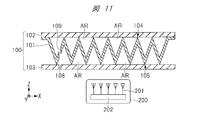
図11に示されるように、実施の形態5では、裏面フィルム103の一部に、裏面フィルム103を貫通する孔108が形成され、樹脂膜101の一部に、樹脂膜101を貫通する孔109が形成されている。
実施の形態5のレドーム100の内部には空気AIRが存在しているが、例えば、天候の変化などにより温度が変化した場合、レドーム100の内部の空気AIRが膨張または伸縮する。例えば、温度が低下すると空気が収縮し、レドーム100の内部の圧力が低くなる。また、温度が上昇すると空気が膨張し、レドーム100の内部の圧力が高くなる。そうすると、レドーム100の内部において、空気AIRの厚さに対して偏差が発生し、等価誘電率が変化し、特性インピーダンスが変化する恐れがある。
従って、レドーム100に孔108および孔109を設けることで、レドーム100の外部の圧力と、レドーム100の内部の圧力とをほぼ同じにすることができる。そのため、上記の恐れを抑制することができる。
このような孔108および孔109の各々のサイズ(口径)は、空気が侵入できる程度の大きさであればよく、例えば窒素分子(N2)および酸素分子(O2)よりも大きい。また、これらのサイズは、液体が侵入できない程度の大きさであることが望ましく、例えば水分子(H2O)よりも小さいことが望ましい。
また、実施の形態5では、孔108および孔109をそれぞれ一個ずつ設けた場合を例示したが、裏面フィルム103に複数の孔108を設け、樹脂膜101に複数の孔109を設けてもよい。また、ミリ波が透過する領域では、各箇所においてミリ波の等価性は出来るだけ均一であることが望ましいため、孔108および孔109は、ミリ波が透過しない箇所に設けられていることが望ましい。
なお、実施の形態5で開示した技術を、実施の形態2~4のレドーム100に適用することもできる。
(変形例3)
以下に、実施の形態4および実施の形態5の変形例3のレドーム100を、図12を用いて説明する。なお、以下の説明では、実施の形態4および実施の形態5との相違点を主に説明する。
以下に、実施の形態4および実施の形態5の変形例3のレドーム100を、図12を用いて説明する。なお、以下の説明では、実施の形態4および実施の形態5との相違点を主に説明する。
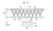
図12に示されるように、変形例3では、樹脂膜101と表面フィルム102との間に、実施の形態4で説明した発泡樹脂膜FP1が充填され、裏面フィルム103に、実施の形態5で説明した孔108が設けられている。このため、変形例3では、発泡樹脂膜FP1を適用することで、レドーム100の機械的強度を向上させることができ、更に、孔108を適用することで、レドーム100の外部の圧力と、レドーム100の内部の圧力とをほぼ同じにすることができる。
(実施の形態6)
以下に、実施の形態6のレドーム100を、図13を用いて説明する。なお、以下の説明では、実施の形態1との相違点を主に説明する。
以下に、実施の形態6のレドーム100を、図13を用いて説明する。なお、以下の説明では、実施の形態1との相違点を主に説明する。
図13に示されるように、実施の形態1では、レドーム100の内部に凹凸形状の樹脂膜101が形成されていたが、実施の形態6では、表面フィルム102と裏面フィルム103との間は、発泡樹脂膜FP2によって充填されている。
発泡樹脂膜FP2は、発泡樹脂膜FP1と同様な樹脂膜であり、樹脂膜101よりも高い発泡率を有し、50~800%程度の発泡率を有する。また、発泡樹脂膜FP1の誘電率は、樹脂膜101の誘電率よりも低く、例えば1.05~2.4である。
実施の形態6において、発泡樹脂膜FP2の発泡率は、一律でなく、厚さ方向(Z方向)で変化しており、表面フィルム102および裏面フィルム103の各々から発泡樹脂膜FP2の中央に向かって、段階的(連続的)に低くなる。すなわち、発泡樹脂膜FP2の誘電率は、発泡樹脂膜FP2の中央から表面フィルム102および裏面フィルム103の各々に向かって、段階的(連続的)に低くなる。
言い換えれば、発泡樹脂膜FP2の厚さ方向(Z方向)において、発泡樹脂膜FP2は、発泡樹脂膜FP2の中央に近い第1領域、第1領域よりも表面フィルム102に近い第2領域、および、第1領域よりも裏面フィルム103に近い第3領域を有する。そして、第2領域および第3領域における発泡樹脂膜FP2の発泡率は、第1領域における発泡樹脂膜FP2の発泡率よりも高く、第2領域および第3領域における発泡樹脂膜FP2の誘電率は、第1領域における発泡樹脂膜FP2の誘電率よりも低い。
表面フィルム102および裏面フィルム103は、発泡樹脂膜FP2中の気泡以外の箇所において、発泡樹脂膜FP2と部分的に接着されている。このため、表面フィルム102および裏面フィルム103の各々と、発泡樹脂膜FP2とを接着させるための接着剤が不要であり、レドーム100の内部における誘電率の増加を抑制することができる。
発泡樹脂膜FP2を構成する樹脂膜は、高い発泡率を有しているので、発泡樹脂膜FP2は、多くの隙間を有し、機械的に脆く、様々なガスを吸着または吸水するという欠点を有する。しかしながら、実施の形態6のように、発泡樹脂膜FP2の表面および裏面に、水性または油性の塗料に対し耐溶剤性を有し、且つ、高い環境耐性を有する表面フィルム102および裏面フィルム103を形成することで、このような欠点を補うことができる。
このように、表面フィルム102と裏面フィルム103との間が、発泡樹脂膜FP2によって充填されていることによって、実施の形態6では、実施の形態1よりもレドーム100の内部における等価誘電率が上昇するが、実施の形態1よりもレドーム100の機械的強度を向上させることができる。
なお、実施の形態6の表面フィルム102上に、実施の形態3で説明した塗膜107を形成することもできる。
(実施の形態7)
以下に、実施の形態7のレドーム100を、図14を用いて説明する。なお、以下の説明では、実施の形態1との相違点を主に説明する。
以下に、実施の形態7のレドーム100を、図14を用いて説明する。なお、以下の説明では、実施の形態1との相違点を主に説明する。
図14に示されるように、実施の形態7では、レドーム100全体に曲面加工が施されている。具体的には、裏面フィルム103から表面フィルム102へ向かう方向に反るように、レドーム100が湾曲されている。このような実施の形態7のレドーム100を形成するためには、まず、図1のレドーム100を準備し、次に、樹脂膜101、表面フィルム102および裏面フィルム103が適度に柔らかくなるまで、レドーム100を加熱し、その後、プレス成型によってレドーム100に曲面加工を施すことで、達成できる。
樹脂膜101全体が曲面形状となるように樹脂膜101を凹凸形状とし、その後、樹脂膜101に表面フィルム102および裏面フィルム103を接着することは、技術的に可能であるが、実際には困難である。実施の形態7のように、凹凸形状の樹脂膜101に表面フィルム102および裏面フィルム103を接着した後に、プレス成型を用いてレドーム100全体に曲面加工を施すことで、加工精度の良いレドーム100を形成することができる。
このように、曲面加工が施されたレドーム100は、様々な自動車のデザインの要求に応じることができる。
なお、実施の形態7で開示した技術を、実施の形態2~6のレドーム100に適用することもできる。
以上、本願発明者らによってなされた発明を実施の形態に基づき具体的に説明したが、本発明は上記実施の形態に限定されるものではなく、その要旨を逸脱しない範囲で種々変更可能である。
例えば、上記実施の形態では、レドーム100が、自動車の前方に取り付けられるバンパである場合を説明したが、レドーム100は、自動車の後方または側方に取り付けられるバンパに適用されてもよい。
また、上記実施の形態では、主に、レーダ200を覆うレドーム100を自動車に使用する場合を説明したが、このようなレドーム100を、鉄道、航空機または船舶などのような他の乗り物に使用することもできる。
100 レドーム
101 樹脂膜
101A 透過領域
101B 固定領域
102 表面フィルム
103 裏面フィルム
104 凸部の頂点
105 凹部の頂点
106 母材
107 塗膜
108、109 孔
200 レーダ
201 アンテナ
202 RF回路
AIR 空気
FP1、FP2 発泡樹脂膜
101 樹脂膜
101A 透過領域
101B 固定領域
102 表面フィルム
103 裏面フィルム
104 凸部の頂点
105 凹部の頂点
106 母材
107 塗膜
108、109 孔
200 レーダ
201 アンテナ
202 RF回路
AIR 空気
FP1、FP2 発泡樹脂膜
Claims (15)
- 表面および裏面を有する樹脂膜と、
前記樹脂膜の前記表面側に形成された第1フィルムと、
前記樹脂膜の前記裏面側に形成された第2フィルムと、
を有し、
前記第1フィルムと前記樹脂膜との間に存在する物質の誘電率、および、前記第2フィルムと前記樹脂膜との間に存在する物質の誘電率は、それぞれ前記樹脂膜の誘電率よりも低い、レドーム。 - 請求項1に記載のレドームにおいて、
前記樹脂膜は、前記裏面側に突出する凹部および前記表面側に突出する凸部が交互に繰り返される形状を成す、レドーム。 - 請求項2に記載のレドームにおいて、
断面視において、前記凹部の頂点と前記凸部の頂点との間の前記樹脂膜の形状は、直線状である、レドーム。 - 請求項2に記載のレドームにおいて、
断面視において、前記凹部の頂点と前記凸部の頂点との間の前記樹脂膜の形状は、曲線状である、レドーム。 - 請求項2に記載のレドームにおいて、
前記樹脂膜は、前記凹部および前記凸部が交互に繰り返される第1領域と、前記第1領域の前記樹脂膜の厚さよりも厚い厚さを有する第2領域とを含む、レドーム。 - 請求項5に記載のレドームにおいて、
前記第1フィルムおよび前記第2フィルムは、前記第1領域の前記樹脂膜を挟み込むように形成され、
前記第2領域の前記樹脂膜の前記表面および前記裏面は、前記第1フィルムおよび前記第2フィルムから露出している、レドーム。 - 請求項2に記載のレドームにおいて、
前記レドームは、前記レドームと異なる構造物に取り付けられた部材である、レドーム。 - 請求項2に記載のレドームにおいて、
前記第1フィルムと前記樹脂膜との間には、空気が存在している、レドーム。 - 請求項8に記載のレドームにおいて、
前記第2フィルムと前記樹脂膜との間には、空気が存在し、
前記第2フィルムの一部には、前記第2フィルムを貫通する第1孔が形成され、
前記樹脂膜の一部には、前記樹脂膜を貫通する第2孔が形成されている、レドーム。 - 請求項2に記載のレドームにおいて、
前記第1フィルムと前記樹脂膜との間には、前記樹脂膜よりも低い誘電率を有する発泡樹脂膜が形成されている、レドーム。 - 請求項10に記載のレドームにおいて、
前記第2フィルムと前記樹脂膜との間には、空気が存在し、
前記第2フィルムの一部には、前記第2フィルムを貫通する第1孔が形成されている、レドーム。 - 請求項1に記載のレドームにおいて、
前記レドームには曲面加工が施されている、レドーム。 - 請求項1に記載のレドームであって、
ミリ波レーダが、前記第2フィルムを介して前記樹脂膜の前記裏面側に設けられるように、前記ミリ波レーダを覆うために用いられる、レドーム。 - 請求項13に記載のレドームにおいて、
前記第1フィルム上に、前記第1フィルムと異なる材料からなる塗膜が形成され、
前記塗膜の厚さおよび前記第1フィルムの厚さの合計の厚さは、前記ミリ波レーダで使用される波長よりも薄い、レドーム。 - 表面および裏面を有する樹脂膜と、
前記樹脂膜の前記表面側に形成された第1フィルムと、
前記樹脂膜の前記裏面側に形成された第2フィルムと、
を有し、
前記樹脂膜は、発泡樹脂膜であり、
前記発泡樹脂膜の厚さ方向において、前記発泡樹脂膜は、前記発泡樹脂膜の中央に近い第1領域、前記第1領域よりも前記第1フィルムに近い第2領域、および、前記第1領域よりも前記第2フィルムに近い第3領域を有し、
前記第2領域および前記第3領域における前記発泡樹脂膜の誘電率は、前記第1領域における前記発泡樹脂膜の誘電率よりも低い、レドーム。
Priority Applications (1)
| Application Number | Priority Date | Filing Date | Title |
|---|---|---|---|
| DE112019004404.4T DE112019004404T5 (de) | 2018-10-12 | 2019-09-03 | Radom |
Applications Claiming Priority (2)
| Application Number | Priority Date | Filing Date | Title |
|---|---|---|---|
| JP2018193271A JP2020060506A (ja) | 2018-10-12 | 2018-10-12 | レドーム |
| JP2018-193271 | 2018-10-12 |
Publications (1)
| Publication Number | Publication Date |
|---|---|
| WO2020075422A1 true WO2020075422A1 (ja) | 2020-04-16 |
Family
ID=70164533
Family Applications (1)
| Application Number | Title | Priority Date | Filing Date |
|---|---|---|---|
| PCT/JP2019/034660 Ceased WO2020075422A1 (ja) | 2018-10-12 | 2019-09-03 | レドーム |
Country Status (3)
| Country | Link |
|---|---|
| JP (1) | JP2020060506A (ja) |
| DE (1) | DE112019004404T5 (ja) |
| WO (1) | WO2020075422A1 (ja) |
Cited By (2)
| Publication number | Priority date | Publication date | Assignee | Title |
|---|---|---|---|---|
| CN115911820A (zh) * | 2021-09-22 | 2023-04-04 | 安弗施无线射频系统(上海)有限公司 | 天线和基站 |
| US20250337158A1 (en) * | 2024-04-25 | 2025-10-30 | Denso Corporation | Radio wave transmissive cover |
Families Citing this family (3)
| Publication number | Priority date | Publication date | Assignee | Title |
|---|---|---|---|---|
| US12553989B2 (en) | 2020-12-25 | 2026-02-17 | Nitto Denko Corporation | Radio wave scattering body, and member for attenuating radio waves comprising radio wave scattering body |
| KR20240035572A (ko) * | 2021-07-21 | 2024-03-15 | 닛토덴코 가부시키가이샤 | 전자파 실드 및 레이더용 커버 |
| JP2024152324A (ja) * | 2023-04-14 | 2024-10-25 | 東芝テック株式会社 | 収納ケース |
Citations (4)
| Publication number | Priority date | Publication date | Assignee | Title |
|---|---|---|---|---|
| JP2003229712A (ja) * | 2002-01-31 | 2003-08-15 | Kanazawa Inst Of Technology | 多層レードーム板およびその製造方法 |
| JP2008249678A (ja) * | 2007-03-02 | 2008-10-16 | Toyota Central R&D Labs Inc | レーダ装置の被覆部品及び貼着部品 |
| US20130321236A1 (en) * | 2012-05-29 | 2013-12-05 | Fredric Paul Ziolkowski | Lightweight, multiband, high angle sandwich radome structure for millimeter wave frequencies |
| WO2017026209A1 (ja) * | 2015-08-07 | 2017-02-16 | 株式会社東海理化電機製作所 | 電波透過部品 |
-
2018
- 2018-10-12 JP JP2018193271A patent/JP2020060506A/ja active Pending
-
2019
- 2019-09-03 WO PCT/JP2019/034660 patent/WO2020075422A1/ja not_active Ceased
- 2019-09-03 DE DE112019004404.4T patent/DE112019004404T5/de not_active Withdrawn
Patent Citations (4)
| Publication number | Priority date | Publication date | Assignee | Title |
|---|---|---|---|---|
| JP2003229712A (ja) * | 2002-01-31 | 2003-08-15 | Kanazawa Inst Of Technology | 多層レードーム板およびその製造方法 |
| JP2008249678A (ja) * | 2007-03-02 | 2008-10-16 | Toyota Central R&D Labs Inc | レーダ装置の被覆部品及び貼着部品 |
| US20130321236A1 (en) * | 2012-05-29 | 2013-12-05 | Fredric Paul Ziolkowski | Lightweight, multiband, high angle sandwich radome structure for millimeter wave frequencies |
| WO2017026209A1 (ja) * | 2015-08-07 | 2017-02-16 | 株式会社東海理化電機製作所 | 電波透過部品 |
Cited By (2)
| Publication number | Priority date | Publication date | Assignee | Title |
|---|---|---|---|---|
| CN115911820A (zh) * | 2021-09-22 | 2023-04-04 | 安弗施无线射频系统(上海)有限公司 | 天线和基站 |
| US20250337158A1 (en) * | 2024-04-25 | 2025-10-30 | Denso Corporation | Radio wave transmissive cover |
Also Published As
| Publication number | Publication date |
|---|---|
| DE112019004404T5 (de) | 2021-05-27 |
| JP2020060506A (ja) | 2020-04-16 |
Similar Documents
| Publication | Publication Date | Title |
|---|---|---|
| JP2020060506A (ja) | レドーム | |
| US10048369B2 (en) | Radar assembly | |
| US6489927B2 (en) | System and technique for mounting a radar system on a vehicle | |
| US20220283264A1 (en) | Corrugated Radomes | |
| JP6440123B2 (ja) | アンテナ装置、無線通信装置、及びレーダ装置 | |
| CN201282193Y (zh) | 毫米波准光集成介质透镜天线及其阵列 | |
| CN101662076B (zh) | 毫米波准光集成介质透镜天线及其阵列 | |
| JP6552326B2 (ja) | 電波透過部品 | |
| JP2008249678A (ja) | レーダ装置の被覆部品及び貼着部品 | |
| WO2005055366A1 (ja) | 車載用レーダ | |
| JP6693682B2 (ja) | レーダ装置 | |
| US20110285604A1 (en) | Radome for broadband parabolic antenna | |
| KR20220012213A (ko) | 적어도 하나의 지향성 안테나를 포함하는 차량 바디 부분 | |
| JP7108930B2 (ja) | アンテナ装置、及び車載ライト装置 | |
| JP2021521577A (ja) | 勾配誘電率フィルム | |
| CN114628895A (zh) | 支持超宽雷达视场的盖板 | |
| US10935655B2 (en) | Surface penetrating radar and battery systems | |
| JP2022519562A (ja) | 電磁伝送減衰制御のための方法および装置 | |
| US20240369677A1 (en) | Radar system for a motor vehicle | |
| JP2022136378A (ja) | 外界センサを有する車体構造 | |
| JP2010091301A (ja) | レーダ装置 | |
| JP2003243920A (ja) | レドーム | |
| EP3994478B1 (en) | Slanted radomes | |
| CN213181997U (zh) | 一种用于车载雷达测试的雷达散射截面增强表面结构 | |
| Hoare et al. | System requirements for automotive radar antennas |
Legal Events
| Date | Code | Title | Description |
|---|---|---|---|
| 121 | Ep: the epo has been informed by wipo that ep was designated in this application |
Ref document number: 19870740 Country of ref document: EP Kind code of ref document: A1 |
|
| 122 | Ep: pct application non-entry in european phase |
Ref document number: 19870740 Country of ref document: EP Kind code of ref document: A1 |