WO2020071210A1 - 摩耗度合い算出装置、摩耗度合い算出方法、摩耗度合い算出プログラムおよび記録媒体 - Google Patents
摩耗度合い算出装置、摩耗度合い算出方法、摩耗度合い算出プログラムおよび記録媒体Info
- Publication number
- WO2020071210A1 WO2020071210A1 PCT/JP2019/037601 JP2019037601W WO2020071210A1 WO 2020071210 A1 WO2020071210 A1 WO 2020071210A1 JP 2019037601 W JP2019037601 W JP 2019037601W WO 2020071210 A1 WO2020071210 A1 WO 2020071210A1
- Authority
- WO
- WIPO (PCT)
- Prior art keywords
- wear
- unit
- degree
- measurement
- measurement target
- Prior art date
- Legal status (The legal status is an assumption and is not a legal conclusion. Google has not performed a legal analysis and makes no representation as to the accuracy of the status listed.)
- Ceased
Links
Images




Classifications
-
- G—PHYSICS
- G01—MEASURING; TESTING
- G01B—MEASURING LENGTH, THICKNESS OR SIMILAR LINEAR DIMENSIONS; MEASURING ANGLES; MEASURING AREAS; MEASURING IRREGULARITIES OF SURFACES OR CONTOURS
- G01B11/00—Measuring arrangements characterised by the use of optical techniques
- G01B11/02—Measuring arrangements characterised by the use of optical techniques for measuring length, width or thickness
- G01B11/06—Measuring arrangements characterised by the use of optical techniques for measuring length, width or thickness for measuring thickness ; e.g. of sheet material
-
- G—PHYSICS
- G01—MEASURING; TESTING
- G01B—MEASURING LENGTH, THICKNESS OR SIMILAR LINEAR DIMENSIONS; MEASURING ANGLES; MEASURING AREAS; MEASURING IRREGULARITIES OF SURFACES OR CONTOURS
- G01B11/00—Measuring arrangements characterised by the use of optical techniques
- G01B11/30—Measuring arrangements characterised by the use of optical techniques for measuring roughness or irregularity of surfaces
-
- G—PHYSICS
- G01—MEASURING; TESTING
- G01B—MEASURING LENGTH, THICKNESS OR SIMILAR LINEAR DIMENSIONS; MEASURING ANGLES; MEASURING AREAS; MEASURING IRREGULARITIES OF SURFACES OR CONTOURS
- G01B21/00—Measuring arrangements or details thereof, where the measuring technique is not covered by the other groups of this subclass, unspecified or not relevant
-
- G—PHYSICS
- G01—MEASURING; TESTING
- G01N—INVESTIGATING OR ANALYSING MATERIALS BY DETERMINING THEIR CHEMICAL OR PHYSICAL PROPERTIES
- G01N21/00—Investigating or analysing materials by the use of optical means, i.e. using sub-millimetre waves, infrared, visible or ultraviolet light
- G01N21/84—Systems specially adapted for particular applications
- G01N21/88—Investigating the presence of flaws or contamination
-
- G—PHYSICS
- G01—MEASURING; TESTING
- G01N—INVESTIGATING OR ANALYSING MATERIALS BY DETERMINING THEIR CHEMICAL OR PHYSICAL PROPERTIES
- G01N21/00—Investigating or analysing materials by the use of optical means, i.e. using sub-millimetre waves, infrared, visible or ultraviolet light
- G01N21/84—Systems specially adapted for particular applications
- G01N21/88—Investigating the presence of flaws or contamination
- G01N21/95—Investigating the presence of flaws or contamination characterised by the material or shape of the object to be examined
Definitions
- the present invention relates to a wear degree calculation device, a wear degree calculation method, a wear degree calculation program, and a recording medium for calculating a wear degree of a measurement target.
- the manhole cover is provided with irregularities such as patterns to prevent automobiles and pedestrians from causing slip accidents. If the irregularities wear due to aging, the height of the irregularities decreases, and the possibility of causing a slip accident increases. In order to prevent such an accident, there is a method of calculating the degree of unevenness of the surface of the measurement target.
- Japanese Patent Application Laid-Open Publication No. 2003-216400 describes that for each of the patch images, the patch image corresponds to the patch image based on the image features of the patch image and the parameters of the wear degree estimator for estimating the wear degree of the unevenness learned in advance.
- a method for estimating the degree of wear of the surface of a measurement object having a concavo-convex pattern is disclosed.
- a main object is to provide a calculation method, a wear degree calculation program, and a recording medium.
- the wear degree calculation device is based on three-dimensional information of a measurement target including a reference surface and a structure provided on the reference surface.
- a measuring unit that measures the height of the structure from the reference plane, and the wear of the measurement target based on a ratio of the height of the structure from the reference plane measured by the measuring unit being within a specific range.
- a calculation unit for calculating the degree of is based on three-dimensional information of a measurement target including a reference surface and a structure provided on the reference surface.
- the wear degree calculation device includes a reference surface and a structure provided on the reference surface. Measuring the height from the reference surface, and the wear degree calculation device calculates the degree of wear of the measurement target based on a ratio of the measured height of the structural portion from the reference surface within a specific range. And calculating.
- the degree of wear of the measurement target can be suitably calculated even when the measurement situation fluctuates.
- FIG. 2 is a functional block diagram illustrating a configuration of the display device according to the first embodiment of the present invention.
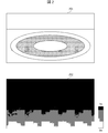
- FIG. 4 is a diagram for explaining distance information corresponding to a reference image according to the first embodiment of the present invention.
- FIG. 4 is a diagram for explaining a measurement target area according to the first embodiment of the present invention. It is a figure for explaining measurement of a height of a measurement point in Embodiment 1 of the present invention.
- FIG. 4 is a diagram illustrating an example of measurement points set by edge detection according to the first embodiment of the present invention.
- 5 is a flowchart illustrating an example of a flow of a control process of the display device according to the first embodiment of the present invention.
- FIG. 4 is a diagram for explaining distance information corresponding to a reference image according to the first embodiment of the present invention.
- FIG. 4 is a diagram for explaining a measurement target area according to the first embodiment of the present invention. It is a figure for explaining measurement of a height of a measurement point in Embod
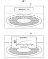
- FIG. 5 is a diagram for describing an example of a method of displaying a degree of wear by a display unit according to the first embodiment of the present invention.
- FIG. 6 is a functional block diagram illustrating a configuration of a display device according to a second embodiment of the present invention. It is a figure in Embodiment 2 of this invention for demonstrating an example of the display method of the degree of abrasion after a predetermined period passes by a display part.
- 9 is a flowchart illustrating an example of a flow of a control process of the display device according to the second embodiment of the present invention.
- One embodiment of the present invention provides a wear degree calculation device that calculates the degree of wear of a measurement target.
- the measurement target of the wear degree calculating device includes a measurement target including a reference surface and a structural portion provided on the reference surface.
- the wear degree calculating device calculates how much the structural part to be measured is worn.
- a case where a manhole cover is measured as a measurement target will be described as an example.
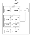
- FIG. 1 is a functional block diagram illustrating a configuration of a display device (wear degree calculating device) 102 according to the first embodiment of the present invention.
- the display device 102 includes a calculation device 101, a stereo imaging unit (distance measurement unit) 103, a distance information acquisition unit (distance measurement unit) 104, a display unit 105, and a storage unit 106.
- the calculation device 101 may be regarded as a wear degree calculation device.
- the stereo imaging unit 103 includes a first imaging unit 107 and a second imaging unit 108.
- the stereo imaging unit 103 outputs the first image generated by the first imaging unit 107 and the second image generated by the second imaging unit 108 to the distance information acquisition unit 104.
- the first imaging unit 107 is installed at a first viewpoint, and generates a first image including a measurement target by imaging a subject.
- the second imaging unit 108 is installed at the second viewpoint, and generates a second image including the measurement target by imaging the subject.
- Examples of the first imaging unit 107 and the second imaging unit 108 include those including an imaging element such as a complementary metal oxide semiconductor (CMOS) and a charge coupled device (CCD) and optical components such as a lens. .
- CMOS complementary metal oxide semiconductor
- CCD charge coupled device
- the distance information acquisition unit 104 acquires three-dimensional information of a measurement target. Specifically, the distance information acquisition unit 104 obtains a three-dimensional measurement target based on distance information indicating a distance between the measurement target and the stereo imaging unit 103 and imaging conditions of the stereo imaging unit 103 such as a focal length or a base line length. Get information. Here, the distance information acquisition unit 104 calculates the parallax from the first image and the second image, and converts the parallax into a distance, so that the position (measurement position) of the stereo imaging unit 103 can be calculated from each position on the measurement target. Obtain distance information indicating the distance to.
- FIG. 2 is a diagram for explaining distance information 202 corresponding to the reference image 201 according to the first embodiment of the present invention.
- the reference image 201 is one of the first image and the second image.
- a distance is stored so as to correspond to each pixel of the reference image 201, and the distance is longer as the subject is farther from the stereo imaging unit 103.
- the distance information acquisition unit 104 outputs the reference image 201 and the three-dimensional information to the calculation device 101.
- the display unit 105 displays the degree of wear of the measurement target output from the calculation device 101, an image recorded in the storage unit 106, and the like.
- FIG. 7 is a diagram for describing an example of a method of displaying the degree of wear of the measurement target on the display unit 105 according to the first embodiment of the present invention.
- the display unit 105 displays the degree of wear of the measurement target by using a text 701, a graph 702, or the like.
- the display unit 105 includes, for example, an LCD (Liquid Crystal Display) and an organic EL display (OELD: Organic ElectroLuminessence Display).
- LCD Liquid Crystal Display
- OELD Organic ElectroLuminessence Display
- the storage unit 106 stores the first image and the second image captured by the stereo imaging unit 103, the three-dimensional information acquired by the distance information acquisition unit 104, the calculation result output from the calculation device 101, and the like in a recording medium.
- the storage unit 106 reads the first image, the second image, the three-dimensional information, the calculation result, and the like recorded on the recording medium, and outputs them to the calculation device 101.
- a general-purpose storage unit can be used as long as it has the above-described functions.
- the calculation device 101 calculates the degree of wear of the measurement target and outputs the calculated degree to the display unit 105 or the storage unit 106. Specifically, as shown in FIG. 2, an uneven structure (structure) for preventing slippage is formed on the surface of the manhole cover, and the calculation device 101 calculates the degree of wear of the structure. I do.
- the calculation device 101 includes a measurement unit 109 and a calculation unit 110.
- the calculation device 101 includes, for example, a CPU (Central Processing Unit) or a GPU (Graphic Processing Unit: image processing device).
- the measurement unit 109 calculates the height of the measurement target structure from the reference plane based on the three-dimensional information of the measurement target acquired from the distance information acquisition unit 104.
- the height of the measurement target structure from the reference plane refers to, for example, the height of an edge that is the distance from the reference plane on which the structure is provided to the edge of the structure. In the structure of the manhole cover, the height of the edge may be referred to as a pattern height.
- the measurement unit 109 calculates a height of the structure from the reference plane by setting a measurement point at an edge of the structure and calculating the height of the measurement point.
- the measurement unit 109 can obtain a distribution of the structure from the reference plane by setting a plurality of measurement points and calculating a height for each measurement point. This will be described in detail below.
- the measuring unit 109 extracts, from the measurement target, a measurement target region that is a region where measurement is performed.
- the measurement target area is an area including the reference plane and the structure. For example, when the measurement target is a manhole cover, the measurement unit 109 sets the center of the manhole cover as the origin, and an elliptical area having the size of the upper, lower, left, and right ends. Is extracted as a measurement target area.
- FIG. 3 is a diagram for explaining a measurement target area according to the first embodiment of the present invention. More specifically, FIG. 3 illustrates a case where the measurement target area 301 is superimposed on the distance information 202.
- the measurement target area 301 is an elliptical area having the center 302 of the manhole cover as the origin, a line connecting the upper end 303 and the lower end 304 as a short axis, and a line connecting the left end 305 and the right end 306 as a long axis.
- the center 302 of the manhole cover and the positions of the upper, lower, left, and right ends may be input by a user using an input device (not shown), or may be automatically detected using image processing.
- the measuring unit 109 measures the distance between the reference plane to be measured and the edge as the height of the edge.
- the measurement unit 109 can use the bottom surface or the surface of the surface on which the design of the manhole cover is provided as a reference surface.
- FIG. 4 is a diagram for describing measurement of the height of the measurement point according to the first embodiment of the present invention. More specifically, FIG. 4A shows a reference image 401 indicating the position of the measurement point, and FIG. 4B shows the depth and height of the distance information from the origin 402 on the z-axis, respectively. Shown by 403 and the y-axis 404.
- the measurement point 405 in FIG. 4 is a measurement point in which the distance information includes a point 407 where the pattern and the bottom surface (reference surface 406) of the manhole cover are in contact.
- the measurement point 408 is a measurement point where a point where the pattern and the reference surface 406 of the manhole cover are in contact is a shielding area 409 where the pattern is shielded.
- the measurement unit 109 calculates the distance between the measurement points 405 and 408 with respect to the reference surface 406 of the manhole cover on which the pattern (structure) is provided, thereby obtaining the height 410 and the measurement point 408 of the measurement point 405. Can be measured respectively.
- the shielding area is generated when the measurement point is measured based on the reference image obtained by obliquely capturing the manhole cover.
- the manhole cover is often installed on a roadway, and it is necessary to measure the measurement point based on a reference image of the manhole cover obliquely taken from a sidewalk or the like in order to safely measure the measurement point. Therefore, a shielding area occurs.
- the measurement unit 109 measures the measurement point based on the reference image of the manhole cover obliquely captured from a sidewalk or the like by setting the distance between the measurement point and the reference plane as the height of the measurement point. Also in this case, it is possible to prevent the number of measurement points from decreasing due to the shielding area.
- the shielding area also occurs at a place where the patterns of the manhole cover are dense, such as when the patterns are adjacent to each other, such as at the measurement point 412, or when the patterns are overlapped.
- the distance between the measurement point and the reference surface 406 of the manhole cover, which is the surface on which the structure is provided, is measured, and the height of the measurement point is used. It is also possible to measure the height of a measurement point whose surface is a shielding area. Thus, a point where the reference plane is a shielding area can be included as a measurement point, so that the number of measurement points can be increased.
- the least square plane of the region is calculated based on the three-dimensional information of each pixel.
- the pixels used for calculation only pixels having a large feature amount such as an edge may be used, or it is not necessary to calculate from all pixels. It is estimated that most of the pixels included in the measurement target area 301 are the bottom surface of the manhole cover or the pattern. Therefore, the calculated plane is located between the bottom surface of the manhole cover and the pattern, and when the calculated plane is viewed from the yz plane, it becomes a line 413 in FIG. 4B. That is, the upper side of the calculated plane is a pattern, and the lower side is a point group belonging to the reference plane.
- the measuring unit 109 can calculate the reference plane from the point group belonging to the reference plane.
- the method of extracting the point group belonging to the reference plane is not limited to the above method.
- a plane corresponding to the road surface on which the manhole cover exists is calculated based on the pixels near the boundary of the set measurement target area 301, and a point group included in a range lower by a certain amount from the plane is set as a reference plane. It can be extracted as a belonging point cloud.
- a point group included in a certain range below a plane indicating a preset threshold value can be extracted as a point group belonging to the reference plane.
- the measurement unit 109 calculates the plane equation of the reference plane 406 of the manhole cover as follows. First, the measuring unit 109 converts the distance information into a three-dimensional point (x, y, z) using Expressions (1) and (2).
- f is the focal length of the stereo imaging unit 103
- u is the position (pixel) in the x-axis direction on the reference image
- v is the position (pixel) in the y-axis direction on the reference image
- w is the x-axis of the reference image.
- the number h of pixels in the direction represents the number of pixels in the y-axis direction of the reference image.
- the measurement unit 109 generates a three-dimensional point group by applying Expressions (1) and (2) to the pixels having the extracted distance information.
- the measuring unit 109 performs principal component analysis on the generated three-dimensional point group.
- the measuring unit 109 uses the third principal component vector obtained by the principal component analysis as a normal vector, and calculates a plane passing through the center of gravity of the three-dimensional point group.
- the normal vector is Expression (3)
- the center of gravity of the three-dimensional point group is (x 0 , y 0 , z 0 )
- the plane equation of the reference surface 406 of the manhole cover is Expression (4).
- the measuring unit 109 measures the height of the measurement point in the manhole cover pattern based on the plane equation of the reference surface 406 of the manhole cover calculated as Expression (4).
- the measurement unit 109 performs edge detection on the measurement target area 301 in the reference image to set a measurement point. Edge detection can be performed using a general edge detector such as a Sobel filter and a Canny method.
- FIG. 5 is a diagram illustrating an example of measurement points set by edge detection according to the first embodiment of the present invention.
- the measurement unit 109 performs edge detection on the measurement target region 301 in the reference image 401, and outputs three-dimensional information of pixels included in the measurement target region 301 and a least square plane used to extract a point group belonging to the reference plane.
- the measurement point is set based on That is, a point group above the least square plane is set as a measurement point.
- the method of extracting the point group belonging to the measurement point may be another method.
- a plane corresponding to the road surface on which the manhole cover exists is calculated based on the pixels near the boundary of the set measurement target area 301, and a point group included in a range lower than the plane by a certain amount is set as a measurement point. It may be extracted as a belonging point group.
- a point group included in a certain range above a plane indicating a preset threshold is extracted as a point group belonging to a measurement point. be able to.
- the extracted point group becomes like a black line edge shown in the reference image 501 in FIG. 5, and the measuring unit 109 sets a pixel forming the black line edge as a measurement point.
- the measurement unit 109 calculates the distance between the measurement point (x, y, z) at the edge and the plane equation of the reference plane 406 of the manhole cover as a reference from Expression (5), and calculates the calculated distance at the measurement point at the edge.
- the height is calculated as
- the measurement unit 109 outputs to the calculation unit 110 the height of the measurement point at the edge of the manhole cover calculated using the plane equation of the reference surface 406 of the manhole cover as a reference.
- the measuring unit 109 may measure a height other than the edge, such as pebbles and sand, as the edge. Therefore, the measurement unit 109 may perform noise removal using the height of the structural unit in the local region from the reference plane in order to reduce the influence of pebbles, sand, and the like.
- the measurement unit 109 sets a local area of a predetermined size such as 10 ⁇ 10 pixels, and calculates a value calculated from the height of the structural unit measured from the reference plane in the local area in the local area.
- the height may be the height of the structure from the reference plane.
- the measuring unit 109 calculates the median of the height from the reference plane of the structure in the local region (one value at the center or the center of the median when the height of the structure from the reference plane is rearranged). (Average of two values), and the height of the structure from the reference plane may be output as the height of the structure from the reference plane.
- the number of measurement points is larger in the manhole cover pattern than in pebble and sand, so even if pebbles and sand are included in the local area, the height of the measurement point at the edge of the manhole cover is the median.
- Is output as For example, when the height of the pebble and sand is about 2 mm and the height of the measuring point is about 5 mm, by outputting about 5 mm serving as a median as the height of the measuring point, the height of the pebble and sand is obtained. There is no need to output about 2 mm as the height of the worn measurement point. Thereby, it is possible to reduce the influence on the degree of wear, such as the wear rate of the measurement point, caused by the entry of pebbles and sand into the manhole cover.
- the calculating unit 110 calculates the ratio of the height of the structural part measured by the measuring unit 109 from the reference plane within a specific range (in the distribution of the height of the structural part measured by the measuring unit 109 from the reference plane, the specific range). Is calculated based on the ratio of the height of the object to be measured). In one aspect, the calculation unit 110 calculates the number of measurement points whose height is equal to or less than ⁇ mm in the distribution of the height of the measurement points measured by the measurement unit 109, and uses the number of all the measurement points as a parameter. By calculating the ratio, the degree of wear of the measurement target is calculated.
- the calculation unit 110 calculates the wear rate at the measurement point as 0.25, that is, 25%.
- the wear rate of the measurement point is almost equal to the area occupied by the area of the pattern where the height of the measurement point is equal to or less than ⁇ mm with respect to the area of the manhole cover. That is, the wear rate at the measurement point indicates how much area the worn area occupies in the entire manhole cover.
- the wear rate of the measurement point can be stably calculated regardless of the measurement target area and the number of the measurement points.
- the wear rate of the measurement points is calculated as a high value
- the wear rate of the measurement points is calculated as a small value.
- the number of measurement points is biased between the near side and the back side of the manhole cover. This is due to the resolution of the pixels, and the measurement points on the near side of the manhole cover, which are close to the stereo imaging unit 103 (photographing distance), are dense, and the measurement points on the far side of the manhole cover, which is far from the photographing distance, are sparse. become.
- the calculation unit 110 may calculate the degree of wear of the measurement target based on information on the distance from the measurement position to the structure to the measurement target. Specifically, the calculation unit 110 calculates the degree of wear of the measurement target by weighting the measurement points according to the position of the structure. Thereby, it is possible to suppress the deviation of the measurement points due to the shooting distance. For example, the weight of a measurement point with a short shooting distance is low, and the weight of a measurement point with a long shooting distance is high, such as 5 points for a measurement point with a short shooting distance and 10 points for a measurement point with a long shooting distance. By doing so, the degree (ratio) of wear can be suitably calculated regardless of the shooting distance.
- the calculation unit 110 determines the measurement points within a specific range among the heights of the measurement points randomly set so that the number of measurement points is equal in each area obtained by equally dividing the measurement target area.
- the height ratio may be calculated. Accordingly, even when the pattern such as a design manhole is asymmetric or the pattern (edge) is unevenly arranged, the ratio of the height of the measurement points in a specific range can be suitably determined regardless of the uneven pattern. Can be calculated.
- the degree of wear of the measurement target based on the ratio of the height of the structure part measured from the reference plane measured by the measurement unit 109 to a specific range, only a part of the measurement target is worn. The user can easily recognize whether the wear has occurred or the wear has occurred.
- the degree of wear of the measurement target to be notified to the user is represented by numerically indicating the degree of wear that is equal to or greater than a predetermined amount of wear (distance between the reference plane and the measurement point).
- the degree of wear of the measurement target to be notified to the user may be notified in a language such as “large wear” and “small wear” based on the calculated degree (rate) of wear of the measurement target. it can. Further, the degree of wear of the measurement target to be notified to the user may be notified by voice or by the color and size of the marker.
- the calculation unit 110 sets in advance the degree of wear (ratio) serving as a determination criterion, and determines that the wear state needs to be replaced based on the degree of wear serving as the determination criterion. It is also possible to notify the user via the display unit 105 or the like. Similarly, the calculation unit 110 can notify the user of the maximum wear amount exceeding the reference wear degree via the display unit 105 or the like.
- FIG. 6 is a flowchart illustrating an example of a flow of a control process of the display device 102 according to the first embodiment of the present invention.
- Step S601 The measurement unit 109 acquires the three-dimensional information of the measurement target acquired by the distance information acquisition unit 104, and a reference image corresponding to the three-dimensional information and in which the measurement target is imaged.
- the reference image acquired by the measurement unit 109 is a first image when the distance information acquisition unit 104 has acquired three-dimensional information based on the first image.
- Step S602 The measurement unit 109 sets a measurement target area in the reference image.
- the measurement unit 109 sets an elliptical region including the center position of the manhole cover and the positions of the upper, lower, left, and right ends as the measurement target region.
- the measurement unit 109 extracts a point group belonging to the bottom surface of the manhole cover in the measurement target area as a point group belonging to the reference plane, and calculates a plane equation of the reference plane of the manhole cover based on the extracted point group.
- Step S603 The measurement unit 109 measures the height of the structure from the reference plane based on the three-dimensional information of the measurement target.
- the measurement unit 109 performs edge detection on the measurement target region in the reference image, and calculates the distance between the measurement point at the detected edge and the reference plane of the measurement target region as the height of the measurement point.
- the measurement unit 109 outputs the distance between the measurement point and the reference surface, which is the surface of the manhole cover on which the structure including the edge is provided, to the calculation unit 110 as the height of the measurement point.
- Step S604 The calculating unit 110 calculates the degree of wear of the measurement target based on the ratio of the height of the structural part measured by the measuring unit 109 from the reference plane within a specific range.
- Step S605 The display unit 105 displays the degree of wear of the measurement target calculated by the calculation unit 110.
- the degree of wear can be accurately calculated.
- the calculation unit 110 calculates the wear rate of the measurement point where the height of the measurement point is equal to or less than ⁇ mm. As described above, in the above-described example, the calculation unit 110 determines that the measurement point having a height equal to or less than the specific height is worn by setting the threshold value of the measurement point at the edge.
- the calculation unit 110 is not limited to this as long as it can calculate the wear rate of the measurement point having a specific range of height.
- the calculation unit 110 sets both the upper limit value and the lower limit value of the measurement point, such as calculating the wear rate of the measurement point where the height of the measurement point is equal to or greater than ⁇ mm and equal to or less than ⁇ mm.
- the degree may be calculated. Thereby, for example, it is possible to calculate the wear rate of the measurement point worn in a specific range of height, such as the height of the measurement point being 0 mm or more and 1 mm or less, or 1 mm or more and 2 mm or less. .
- the influence of noise due to the pebbles and the sand can be eliminated by calculating the wear rate of the measurement point having a height of 3 mm or more and 5 mm or less. .
- the calculation unit 110 may cause the display unit 105 to display information other than the degree of wear of the measurement target.
- the calculation unit 110 causes the display unit 105 to display information on the height from the reference plane of the structure having a height outside a specific range among the measured heights of the structure from the reference plane. Is also good.
- the calculation unit 110 regards a measurement point having a height outside a specific range as a worn measurement point, and informs the user via the display unit 105 that there is a worn measurement point. It may be. Specifically, when there is a measurement point whose height of the measurement point is equal to or less than ⁇ mm, the calculation unit 110 may notify the user by displaying on the display unit 105 that there is a measurement point whose height is equal to or less than ⁇ mm. . For example, it is assumed that the manhole cover needs to be replaced if there is at least one place where the height of the measurement point is equal to or less than ⁇ mm in the measurement target area of the manhole cover.
- the calculation unit 110 may cause the display unit 105 to display an indication that "there is a place where the height of the measurement point is equal to or less than ⁇ mm". In addition, the calculation unit 110 may cause the display unit 105 to highlight the location where the height of the measurement point is equal to or less than ⁇ mm. This can prompt the user to replace the manhole cover.
- the display unit 105 displays the degree of wear, for example, the wear rate of the measurement point.
- the height of the structure from the reference plane may be further displayed.
- the display unit 105 may highlight a reference surface such as a reference surface of a manhole cover as a reference for measuring the height of the structure unit from the reference surface by coloring or the like.
- the display unit 105 may display a value output in the process of calculating the degree of wear. Accordingly, for example, a portion where the measurement point is worn on a measurement target such as a manhole cover, and a reference plane that is a reference for measuring the height of the measurement point can be displayed in an easily understandable manner.
- the measurement unit 109 measures the height of the structure unit from the reference surface using the surface of the manhole cover on which the pattern (structure) is provided as the reference surface.
- the measurement unit 109 may measure the height from the second reference plane different from the reference plane as the height of the structure unit from the reference plane.
- the storage unit 106 stores the second reference plane of the measurement target so as to be switchable with the first reference plane
- the measurement unit 109 stores the second reference plane when the first reference plane and the second reference plane are switched.
- the height from the reference plane may be measured as the height of the structure from the reference plane.
- the storage unit 106 can switch a previously calculated plane equation of the reference plane (first reference plane) of the manhole cover to a newly calculated plane equation of the reference plane (second reference plane) of the manhole cover. You may memorize it. It is also assumed that the newly calculated plane equation of the reference plane of the manhole cover and the previously calculated plane equation of the reference plane of the manhole cover have been switched. In this case, the measuring unit 109 may measure the distance between the reference plane equation of the manhole cover calculated in the past and the measurement point at the edge as the height of the measurement point at the edge. This makes it possible to measure the height of the structural part from the reference plane even when it is difficult to calculate the measurement target reference plane such as the plane equation of the reference plane of the manhole cover due to the influence of noise or the like.
- the measuring unit 109 measures the height of the measurement point using the plane as the reference plane (the reference plane and the second reference plane). Good.
- the measurement unit 109 sets the equation of the reference plane to the equation of the spherical surface, sets a measurement point on the edge of the uneven pattern height provided on the spherical surface, and measures the distance between the spherical surface and the measurement point.
- the present invention can be applied to measurement of the height of a measurement point of a spherical measurement target having an uneven pattern or the like.
- the measurement unit 109 sets the elliptical area as the measurement target area, but may set an arbitrary shaped area such as a circle, a square, and a polygon as the measurement target area.
- an area of an arbitrary shape as the measurement target area, the degree (ratio) of wear can be calculated for a measurement target other than the manhole cover in which the measurement target area becomes an elliptical area when imaged obliquely.
- a visible light camera is used as the stereo imaging unit 103, but an invisible light camera such as an infrared camera may be used. Also in this case, by obtaining the first image and the second image from the stereo imaging unit 103 using the invisible light camera and inputting them to the distance information obtaining unit 104, the same effect as in the case using the visible light camera is obtained. be able to.
- the distance information is acquired by the stereo imaging unit 103, but the distance information acquisition unit 104 may acquire the distance information.
- the distance information acquisition unit 104 may include, for example, a LIDAR (Light Detection and Ranging) or an infrared TOF (Time of Flight) sensor.
- the configuration may not include the imaging unit.
- the measuring unit 109 can detect an edge based on only the distance information.
- the display unit 105 displays the degree of wear on the manhole cover.
- the measurement target may be a tile on an outer wall or a block on a breakwater.
- the display unit 105 displays the reference plane of the structure having an ⁇ mm or more. May be displayed. Thereby, it is possible to display the rattling of the tiles on the outer wall or the blocks of the breakwater.
- the degree of wear is calculated.
- the degree of wear after a predetermined period has elapsed may be further predicted.
- a display device 802 and a method of controlling the display device 802 (a method of controlling the calculation device 801) according to the second embodiment of the present invention will be described below with reference to FIGS.
- the same members as those in the first embodiment are denoted by the same reference numerals, and the detailed description is omitted.
- FIG. 8 is a functional block diagram illustrating a configuration of the display device 802 according to the second embodiment of the present invention. As illustrated in FIG. 8, the display device 802 includes a calculation device 801 instead of the calculation device 101 of the display device 102 according to the first embodiment. Except for this point, the display device 802 has the same configuration as the display device 102 according to the first embodiment.
- the calculation device 801 further includes a holding unit 803 and a prediction unit 804 in addition to the components included in the calculation device 101 according to the first embodiment. Except for this point, the calculation device 801 according to the second embodiment has the same configuration as the calculation device 101 according to the first embodiment.
- the holding unit 803 holds the degree of abrasion calculated by the calculation unit 110 and outputs it to the prediction unit 804.
- the holding unit 803 holds the wear rates of the measurement points at the edge of the same manhole cover measured at different dates and times in chronological order for each manhole cover. Then, the holding unit 803 specifies the same manhole cover measured at different dates and times by using the number assigned to the manhole cover, the position (latitude and longitude) of the manhole cover, and the like. The number and the position may be input by the user to the holding unit 803 via an input unit (not shown), or may be automatically obtained from the value of the position information sensor by providing the holding unit 803 with a position information sensor. May be.
- the prediction unit 804 predicts the degree of wear after a predetermined period has elapsed based on the degree of wear held in the holding unit 803. In one aspect, the prediction unit 804 may further refer to the degree of wear calculated by the calculation unit 110. Then, the prediction unit 804 outputs a predicted value indicating a degree of wear after a predetermined period has elapsed, for example, to the display unit 105 or the storage unit 106 in the future.
- the user can estimate the replacement time of the manhole cover and the like, and can plan the replacement of the manhole cover in advance.
- the prediction unit 804 may predict the degree of wear after a predetermined period has elapsed by extrapolation (linear extrapolation) using a linear function. For example, if the wear rate of the current measurement point is 20% and the wear rate of the measurement point six months ago is 15%, the wear rate of the measurement point increases by 5% in six months. Assuming that the increase in the wear rate at the measurement point continues to occur, the change in the wear rate at the measurement point six months later is 5%, and the wear rate at the measurement point six months later can be predicted to be 25%.
- the prediction unit 804 sets the predicted value indicated by the wear rate of the measurement point after the lapse of the predetermined period to 100%, and sets the predicted value to 100%. Output to 106.
- the display unit 105 that has obtained the predicted value of the degree of wear after the elapse of the predetermined period output from the prediction unit 804 may display the predicted value, for example, as illustrated in FIG.
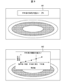
- FIG. 9 is a diagram for explaining an example of a method of displaying the degree of wear after a predetermined period has elapsed by the display unit 105 according to the second embodiment of the present invention.
- FIG. 9 is a diagram for explaining a method of displaying the wear rate of the measurement point after a predetermined period has elapsed by the display unit 105.
- the display unit 105 displays a predicted value indicated by the wear rate of the measurement point after a predetermined period has elapsed by using a text 901 or a graph 902.
- the prediction unit 804 may output an error signal along with the predicted value to the display unit 105 or the like. This allows the user to be notified that an abnormality has occurred in the manhole cover or the internal processing of the prediction unit 804.
- FIG. 10 is a flowchart illustrating an example of the flow of a control process of the display device 802 according to the second embodiment of the present invention.
- Steps S1001 to S1004 are the same as Steps S601 to S604 of the control processing of the display device 102 according to the first embodiment, and thus description thereof will be omitted.
- Step S1005 The holding unit 803 holds the degree of wear calculated by the calculation unit 110. Subsequently, the holding unit 803 outputs the held degree of wear to the prediction unit 804.
- Step S1006 The prediction unit 804 predicts the degree of wear after a predetermined period has elapsed based on the held degree of wear.
- the prediction unit 804 outputs the predicted degree of wear after a predetermined period has elapsed to the display unit 105.
- Step S1007 The display unit 105 displays a predicted value indicating the degree of wear after the predicted predetermined period has elapsed.
- the degree of wear (rate) after a predetermined period of time can be predicted based on the calculated degree of wear and the degree of wear held.
- a predicted value indicating the degree (ratio) of the wear can be displayed.
- the prediction unit 804 predicts the degree of wear after a predetermined period has elapsed by extrapolation (linear extrapolation) based on a linear function.
- the present embodiment is not limited to this.
- the prediction unit 804 may predict the degree of wear after a predetermined period has elapsed, for example, by extrapolation based on a quadratic function. This makes it possible to accurately predict the degree of wear of not only the measurement target that linearly wears but also the measurement target having other characteristics. Further, the prediction unit 804 may use a value obtained by performing weighted averaging on the time-series data and smoothing the value as a change in the degree of wear after a predetermined period has elapsed. Then, the prediction unit 804 may predict the degree of wear after a predetermined period has elapsed based on the change in the degree of wear. This makes it possible to appropriately calculate the degree of wear (rate) after a predetermined period has elapsed, with emphasis on the degree of wear calculated near the present time.
- the prediction unit 804 be capable of switching the above-described prediction method. This allows the user to arbitrarily select a prediction method via the input unit (not shown).
- the prediction unit 804 may integrate and output a predicted value indicated by the degree of height in a specific range after a predetermined period predicted by a plurality of prediction methods. In this case, for example, the prediction unit 804 averages and outputs a plurality of predicted values. This makes it possible to output a stable predicted value.
- control blocks of the calculation device 101 and the calculation device 801 are realized by a logic circuit (hardware) formed in an integrated circuit (IC chip) or the like. Or may be realized by software.
- the calculation device 101 and the calculation device 801 each include a computer that executes instructions of a calculation program that is software for realizing each function.
- the computer includes, for example, at least one processor (control device) and at least one computer-readable recording medium storing the calculation program.
- the computer also includes an OS (Operating System) and hardware such as peripheral devices. Then, in the computer, the object of the present invention is achieved by the processor reading and executing the calculation program from the recording medium.
- CPU Central Processing Unit
- the recording medium include “temporary tangible media”, for example, portable media such as ROM (Read Only Memory) and CD-ROM, disks such as tapes, flexible disks and magneto-optical disks, cards, semiconductor memories, A programmable logic circuit, a hard disk incorporated in a computer system, or the like can be used.
- the computer-readable recording medium include a network such as the Internet, and a communication line for transmitting the calculation program via a communication line such as a telephone line. One that holds the calculation program, and one that holds the calculation program for a certain period of time, such as a volatile memory inside a computer system serving as a server and a client.
- the calculation device 101 and the calculation device 801 may further include a RAM (Random Access Memory) for expanding the calculation program. Further, the program may be supplied to the computer via an arbitrary transmission medium (such as a communication network and a broadcast wave) capable of transmitting the calculation program. Note that one embodiment of the present invention can also be realized in the form of a data signal embedded in a carrier wave, in which the calculation program is embodied by electronic transmission.
- a RAM Random Access Memory
- part or all of the calculation device 101 and the calculation device 801 may be realized as an LSI that is typically an integrated circuit.
- the control blocks of the calculation device 101 and the calculation device 801 may be individually formed into chips, or a part or all of them may be integrated and formed into a chip.
- the method of circuit integration is not limited to LSI, but may be realized by a dedicated circuit or a general-purpose processor. Further, in the case where a technology for forming an integrated circuit that replaces the LSI appears due to the advance of the semiconductor technology, an integrated circuit based on the technology can be used.
- control lines and the information lines indicate what is considered necessary for the description, and not all the control lines and the information lines are necessarily shown on the product. May be connected to each other.
- the abrasion degree calculating device is configured such that, based on three-dimensional information of a measurement target including a reference surface and a structure provided on the reference surface, a height of the structure from the reference surface is measured.
- a measuring unit that measures the height, based on the ratio of the height of the structural unit measured by the measuring unit from the reference plane is a specific range, a calculating unit that calculates the degree of wear of the measurement target, It has.
- the calculation unit calculates the degree of wear of the measurement target based on distance information from a measurement position to the measurement target to the structure. May be.
- the wear degree calculating device in the above aspect 1 or 2, wherein the holding unit that holds the degree of wear of the measurement target calculated by the calculation unit, and the holding unit that is held by the holding unit
- the apparatus may further include a prediction unit that predicts the degree of wear of the measurement target in the future based on the degree of wear of the measurement target.
- the measurement target may be a manhole cover, an outer wall tile, or a breakwater block.
- the wear degree calculating device in any one of the first to fourth aspects, further includes a distance measuring unit that generates the three-dimensional information and a display unit that displays the degree of wear of the measurement target calculated by the calculation unit. And may be further provided.
- the wear degree calculating device may include a reference surface and a structural portion provided on the reference surface, based on three-dimensional information of a measurement target including the structural portion. Measuring the height from the reference surface, and the wear degree calculation device calculates the degree of wear of the measurement target based on a ratio of the measured height of the structural portion from the reference surface within a specific range. And calculating.
- the calculation device may be realized by a computer.
- the calculation device is realized by a computer by operating the computer as each unit (software element) included in the calculation device.
- the calculation program of the calculation device and a computer-readable recording medium storing the calculation program are also included in the scope of the present invention.
Landscapes
- Physics & Mathematics (AREA)
- General Physics & Mathematics (AREA)
- Health & Medical Sciences (AREA)
- Life Sciences & Earth Sciences (AREA)
- Chemical & Material Sciences (AREA)
- Analytical Chemistry (AREA)
- Biochemistry (AREA)
- General Health & Medical Sciences (AREA)
- Immunology (AREA)
- Pathology (AREA)
- Length Measuring Devices By Optical Means (AREA)
- Investigating Materials By The Use Of Optical Means Adapted For Particular Applications (AREA)
Abstract
計測状況が変動する場合であっても、計測対象物の摩耗の度合いを好適に算出することができる摩耗度合い算出装置等を提供する。算出装置は、計測対象に対する計測位置の三次元情報に基づいて、構造部の高さを計測する計測部と、計測部が計測した構造部の基準面からの高さが特定の範囲である割合に基づいて、計測対象の摩耗の度合いを算出する算出部と、を備えている。
Description
本発明は、計測対象の摩耗度合いを算出する摩耗度合い算出装置、摩耗度合い算出方法、摩耗度合い算出プログラムおよび記録媒体に関する。
本願は、2018年10月2日に、日本に出願された特願2018-187617に優先権を主張し、その内容をここに援用する。
本願は、2018年10月2日に、日本に出願された特願2018-187617に優先権を主張し、その内容をここに援用する。
マンホール蓋は、自動車および歩行者などがスリップ事故を引き起こすことを防ぐために模様などの凸凹を備えている。当該凹凸が経年劣化によって摩耗すると、凹凸の高さが低下し、スリップ事故を引き起こす可能性が高くなる。このような事故を防ぐために、計測対象の表面の凸凹の摩耗の度合いを算出する方法がある。
例えば、下記特許文献1には、パッチ画像の各々について、パッチ画像の画像特徴と、予め学習された凹凸の摩耗度を推定するための摩耗度推定器のパラメータと、に基づいてパッチ画像に対応する、凸凹模様を持つ計測対象の表面の摩耗度を推定する方法が開示されている。
しかしながら、特許文献1に記載された方法では、マンホール蓋全体の凹凸の摩耗度を算出する際に、パッチ画像の各々の凹凸の摩耗度の平均値を用いるため、全体的に摩耗している場合と、一部分だけ強く摩耗している場合とを区別することが困難である。また、マンホール蓋は屋外に設置されていることが多く、小石や砂などによるノイズにより、計測ごとに計測状況が変動することが考慮されていない。
本発明の一態様は上記課題を鑑みてなされたものであり、計測状況が変動する場合であっても、計測対象物の摩耗の度合いを好適に算出することができる摩耗度合い算出装置、摩耗度合い算出方法、摩耗度合い算出プログラムおよび記録媒体を提供することを主たる目的とする。
上記の課題を解決するために、本発明の一態様に係る摩耗度合い算出装置は、基準面と、該基準面上に設けられた構造部とを備える計測対象の三次元情報に基づいて、当該構造部の前記基準面からの高さを計測する計測部と、前記計測部が計測した前記構造部の前記基準面からの高さが特定の範囲である割合に基づいて、前記計測対象の摩耗の度合いを算出する算出部と、を備えている。
本発明の一態様に係る摩耗度合い算出方法は、摩耗度合い算出装置が、基準面と、該基準面上に設けられた構造部とを備える計測対象の三次元情報に基づいて、当該構造部の前記基準面からの高さを計測することと、摩耗度合い算出装置が、計測した前記構造部の前記基準面からの高さが特定の範囲である割合に基づいて、前記計測対象の摩耗の度合いを算出することとを、を含む。
本発明の一態様によれば、計測状況が変動する場合であっても、計測対象物の摩耗の度合いを好適に算出することができる。
本発明の一態様は、計測対象の摩耗の度合いを算出する摩耗度合い算出装置を提供する。摩耗度合い算出装置の計測対象としては、基準面と、該基準面上に設けられた構造部とを備える計測対象が挙げられる。摩耗度合い算出装置は、計測対象の構造部がどの程度摩耗しているかを算出する。以下では、一例として、計測対象としてマンホールの蓋を計測する場合について説明する。
<実施形態1>
図1は、本発明の実施形態1に係る表示装置(摩耗度合い算出装置)102の構成を示す機能ブロック図である。図1に示すように、表示装置102は、算出装置101、ステレオ撮像部(測距部)103、距離情報取得部(測距部)104、表示部105、および記憶部106を備えている。なお、他の観点において、算出装置101が摩耗度合い算出装置であるとみなしてもよい。
図1は、本発明の実施形態1に係る表示装置(摩耗度合い算出装置)102の構成を示す機能ブロック図である。図1に示すように、表示装置102は、算出装置101、ステレオ撮像部(測距部)103、距離情報取得部(測距部)104、表示部105、および記憶部106を備えている。なお、他の観点において、算出装置101が摩耗度合い算出装置であるとみなしてもよい。
[ステレオ撮像部103]
ステレオ撮像部103は、第一撮像部107と第二撮像部108とから構成される。ステレオ撮像部103は、第一撮像部107によって生成された第一画像および第二撮像部108によって生成された第二画像を距離情報取得部104に出力する。
ステレオ撮像部103は、第一撮像部107と第二撮像部108とから構成される。ステレオ撮像部103は、第一撮像部107によって生成された第一画像および第二撮像部108によって生成された第二画像を距離情報取得部104に出力する。
(第一撮像部107、第二撮像部108)
第一撮像部107は、第一視点に設置されており、被写体を撮像することによって計測対象を含む第一画像を生成する。第二撮像部108は、第二視点に設置されており、被写体を撮像することによって計測対象を含む第二画像を生成する。第一撮像部107および第二撮像部108としては、CMOS(Complementary Metal Oxide Semiconductor)およびCCD(Charge Couple Device)などの撮像素子と、レンズなどの光学部品とを備えているものを挙げることができる。
第一撮像部107は、第一視点に設置されており、被写体を撮像することによって計測対象を含む第一画像を生成する。第二撮像部108は、第二視点に設置されており、被写体を撮像することによって計測対象を含む第二画像を生成する。第一撮像部107および第二撮像部108としては、CMOS(Complementary Metal Oxide Semiconductor)およびCCD(Charge Couple Device)などの撮像素子と、レンズなどの光学部品とを備えているものを挙げることができる。
[距離情報取得部104]
距離情報取得部104は、計測対象の三次元情報を取得する。具体的には、距離情報取得部104は、計測対象とステレオ撮像部103との距離を示す距離情報と、焦点距離または基線長などのステレオ撮像部103の撮像条件とから、計測対象の三次元情報を取得する。ここで、距離情報取得部104は、第一画像と第二画像とから視差を算出し、視差を距離に変換することで、ステレオ撮像部103の位置(計測位置)から計測対象上の各位置までの距離を示す距離情報を取得する。
距離情報取得部104は、計測対象の三次元情報を取得する。具体的には、距離情報取得部104は、計測対象とステレオ撮像部103との距離を示す距離情報と、焦点距離または基線長などのステレオ撮像部103の撮像条件とから、計測対象の三次元情報を取得する。ここで、距離情報取得部104は、第一画像と第二画像とから視差を算出し、視差を距離に変換することで、ステレオ撮像部103の位置(計測位置)から計測対象上の各位置までの距離を示す距離情報を取得する。
以下に、距離情報取得部104が取得した距離情報について図2を用いて説明する。図2は、本発明の実施形態1における基準画像201に対応する距離情報202を説明するための図である。基準画像201は、第一画像および第二画像のうちの一方の画像である。距離情報202は、基準画像201の各画素に対応するように距離が格納されており、ステレオ撮像部103から遠い被写体ほど距離は長くなる。
図2では、距離が短いほど明るい画素によって表され、距離が長いほど暗い画素で表されている。距離情報取得部104は、基準画像201と、三次元情報とを算出装置101に出力する。
[表示部105]
表示部105は、算出装置101から出力される計測対象の摩耗度合いおよび記憶部106に記録された画像などを表示する。
表示部105は、算出装置101から出力される計測対象の摩耗度合いおよび記憶部106に記録された画像などを表示する。
以下に図7を用いて表示部105による計測対象の摩耗度合いの表示方法の一例について説明する。図7は、本発明の実施形態1における、表示部105による計測対象の摩耗度合いの表示方法の一例について説明するための図である。図7に示すように、表示部105は、計測対象の摩耗度合いをテキスト701またはグラフ702などによって表示する。
表示部105は、例えば、LCD(Liquid Crystal Display)および有機ELディスプレイ(OELD:Organic ElectroLuminessence Display)などによって構成される。
[記憶部106]
記憶部106は、ステレオ撮像部103によって撮像された第一画像および第二画像、距離情報取得部104によって取得された三次元情報、ならびに、算出装置101から出力される算出結果などを記録媒体に記憶する。また、記憶部106は、記録媒体に記録される第一画像、第二画像、三次元情報および算出結果などを読み込んで、算出装置101に出力する。記憶部106としては、上述の機能を有するものであれば、汎用のものを用いることができる。
記憶部106は、ステレオ撮像部103によって撮像された第一画像および第二画像、距離情報取得部104によって取得された三次元情報、ならびに、算出装置101から出力される算出結果などを記録媒体に記憶する。また、記憶部106は、記録媒体に記録される第一画像、第二画像、三次元情報および算出結果などを読み込んで、算出装置101に出力する。記憶部106としては、上述の機能を有するものであれば、汎用のものを用いることができる。
[算出装置101]
算出装置101は、計測対象の摩耗の度合いを算出し、表示部105または記憶部106に出力する。詳細には、図2に示すように、マンホールの蓋の表面には、滑り止めのための凹凸構造(構造部)が形成されており、算出装置101は、当該構造部の摩耗の度合いを算出する。
算出装置101は、計測対象の摩耗の度合いを算出し、表示部105または記憶部106に出力する。詳細には、図2に示すように、マンホールの蓋の表面には、滑り止めのための凹凸構造(構造部)が形成されており、算出装置101は、当該構造部の摩耗の度合いを算出する。
算出装置101は、計測部109と算出部110とを備えている。算出装置101は、例えばCPU(Central Processing Unit:中央処理装置)またはGPU(Graphic Processing Unit:画像処理用処理装置)などから構成される。
(計測部109)
計測部109は、距離情報取得部104から取得した計測対象の三次元情報に基づいて、計測対象の構造部の基準面からの高さを算出する。計測対象の構造部の基準面からの高さとは、例えば、構造部が設けられた基準面から構造部のエッジ部分までの距離であるエッジの高さのことを指す。また、マンホールの蓋の構造部においては、当該エッジの高さは、模様高さとも称されることがある。
計測部109は、距離情報取得部104から取得した計測対象の三次元情報に基づいて、計測対象の構造部の基準面からの高さを算出する。計測対象の構造部の基準面からの高さとは、例えば、構造部が設けられた基準面から構造部のエッジ部分までの距離であるエッジの高さのことを指す。また、マンホールの蓋の構造部においては、当該エッジの高さは、模様高さとも称されることがある。
一態様において、計測部109は、構造部のエッジに計測点を設定し、当該計測点の高さを算出することにより、構造部の基準面からの高さを算出する。また、計測部109は、複数の計測点を設定し、計測点ごとの高さを算出することにより、構造部の基準面からの分布を取得することができる。以下詳細に説明する。
まず、計測部109は、計測対象から、計測を行う領域となる計測対象領域を抽出する。計測対象領域は、基準面および構造部を含む領域であり、例えば、計測対象がマンホール蓋である場合、計測部109は、マンホール蓋の中心を原点とし、上下左右端の大きさとなる楕円の領域を、計測対象領域として抽出する。
図3を用いて計測対象領域についてより具体的に説明する。図3は、本発明の実施形態1における計測対象領域を説明するための図である。より具体的には、図3は、距離情報202に計測対象領域301を重畳したものを示している。計測対象領域301は、マンホール蓋の中心302を原点とし、上端303と下端304とを結ぶ線分を短軸、左端305と右端306とを結ぶ線分を長軸とした楕円の領域である。マンホール蓋の中心302および上下左右端の位置は、入力装置(不図示)にてユーザが入力してもよいし、画像処理を用いて自動で検出するようにしてもよい。
計測部109は、計測対象の基準面とエッジとの距離をエッジの高さとして計測する。例えば、被写体である計測対象がマンホール蓋の場合、計測部109は、マンホール蓋の模様がある面の底面または表面を基準面とすることができる。
以下に、図4を用いてエッジにおける計測点の高さの計測について説明する。図4は、本発明の実施形態1における計測点の高さの計測について説明するための図である。より具体的には、図4の(a)は、計測点の位置を示す基準画像401を示し、図4の(b)は、原点402からの距離情報の奥行および高さを、それぞれz軸403およびy軸404によって表したものを示す。
図4の計測点405は、模様とマンホール蓋の底面(基準面406)とが接する点407が距離情報に含まれている計測点である。計測点408は、模様とマンホール蓋の基準面406とが接する点が模様によって遮蔽されている遮蔽領域409となっている計測点である。
計測部109は、模様(構造部)が設けられている面であるマンホール蓋の基準面406に対する計測点405および408の距離をそれぞれ算出することで、計測点405の高さ410および計測点408の高さ411をそれぞれ計測することができる。
遮蔽領域は、マンホール蓋が斜めに撮像された基準画像に基づいて計測点を計測した場合に発生する。マンホール蓋は車道上に設置されていることが多く、安全に計測点の計測を行うためには歩道などから斜めに撮像されたマンホール蓋の基準画像に基づいて計測点を計測する必要がある。そのため、遮蔽領域が発生する。
これに対し、計測部109は、計測点と基準面との距離を計測点の高さとすることで、歩道などから斜めに撮像されたマンホール蓋の基準画像に基づいて計測点の計測を行った場合にも、遮蔽領域による計測点の減少を防ぐことができる。
また、遮蔽領域は、例えば、計測点412のように模様が隣り合っていたり、模様が重なり合っていたりするなど、マンホール蓋の模様が密集している箇所においても発生する。
そのような場合でも、上述の例のように、計測点と、構造部が設けられている面であるマンホール蓋の基準面406との距離を計測して計測点の高さとすることで、基準面が遮蔽領域となっている計測点の高さも計測できる。これにより、基準面が遮蔽領域となっている点も計測点として含めることができるため、計測点の数を増やすことができる。
次に、計測部109によるマンホール蓋の基準面406の平面方程式を算出する方法を説明する。まず、設定された計測対象領域301に含まれる画素から、各画素の三次元情報に基づいて当該領域の最小二乗平面を算出する。算出に使用する画素は、エッジなどの特徴量が大きい画素のみを使用してもよく、全画素から算出しなくてもよい。計測対象領域301に含まれる画素は、多くがマンホール蓋の底面、または、模様であることが推定される。そのため、算出された平面は、マンホール蓋の底面と模様との間に位置し、算出された平面をyz平面から見ると図4の(b)の線413のようになる。すなわち、算出された平面より上側が模様、下側が基準面に属す点群となる。計測部109は、当該基準面に属す点群から基準面を算出することができる。
ここで、基準面に属す点群を抽出する方法は上述の方法に限定されない。例えば、設定された計測対象領域301の境界付近の画素に基づいてマンホール蓋が存在する道路面に相当する平面を算出し、当該平面から一定量下側の範囲に含まれる点群を基準面に属する点群として抽出することができる。また、撮影する角度および距離が固定である場合には、予め設定された閾値を示す平面の下側の一定範囲に含まれる点群を、基準面に属する点群として抽出することができる。
より具体的には、計測部109は、以下のようにマンホール蓋の基準面406の平面方程式を算出する。まず、計測部109は、式(1)および(2)を用いて当該距離情報を三次元点(x、y、z)に変換する。


ここで、fはステレオ撮像部103の焦点距離、uは基準画像上のx軸方向の位置(画素)、vは基準画像上のy軸方向の位置(画素)、wは基準画像のx軸方向の画素数、hは基準画像のy軸方向の画素数を表す。
計測部109は、抽出した距離情報を有する画素に式(1)および(2)を適用して三次元点群を生成する。計測部109は、生成された三次元点群に対し、主成分分析を施す。計測部109は、主成分分析によって得られた第三主成分ベクトルを法線ベクトルとし、かつ、三次元点群の重心を通る平面を算出する。ここで、法線ベクトルを式(3)、三次元点群の重心を(x0、y0、z0)とすると、マンホール蓋の基準面406の平面方程式は式(4)となる。


計測部109は、式(4)として算出されたマンホール蓋の基準面406の平面方程式を基準とし、マンホール蓋の模様における計測点の高さを計測する。計測部109は、計測点を設定するために、基準画像中の計測対象領域301に対してエッジ検出を行う。エッジ検出は一般的なエッジ検出器であるソーベルフィルタおよびキャニー法などを用いることで行うことができる。
以下に、エッジ検出によって設定された計測点の具体例について図5を用いて説明する。図5は、本発明の実施形態1におけるエッジ検出によって設定された計測点の一例を示す図である。計測部109は、基準画像401における計測対象領域301にエッジ検出を行い、計測対象領域301に含まれる画素の三次元情報と、基準面に属する点群を抽出するのに使用した最小二乗平面、とに基づいて計測点を設定する。すなわち、最小二乗平面より上側の点群を計測点として設定する。
ここで、計測点に属す点群を抽出する方法は他の方法でもよい。例えば、設定された計測対象領域301の境界付近の画素に基づいてマンホール蓋が存在する道路面に相当する平面を算出し、当該平面から一定量下側の範囲に含まれる点群を計測点に属する点群として抽出してもよい。また、ステレオ撮像部103にから撮影する角度および距離が固定である場合には、予め設定された閾値を示す平面の上側の一定範囲に含まれる点群を、計測点に属する点群として抽出することができる。
抽出された点群は図5の基準画像501に示す黒線のエッジのようになり、計測部109は、当該黒線のエッジを形成する画素を計測点として設定する。計測部109は、エッジにおける計測点(x、y、z)と、基準となるマンホール蓋の基準面406の平面方程式との距離を式(5)から算出し、算出した距離をエッジにおける計測点の高さとして算出する。計測部109は、基準となるマンホール蓋の基準面406の平面方程式を用いて算出したマンホール蓋のエッジにおける計測点の高さを算出部110に出力する。

ここで、マンホール蓋は屋外に設置されているため、計測部109が、小石および砂など、エッジ以外の高さをエッジとして計測してしまう可能性がある。そのため、計測部109は、小石および砂などの影響を低減するために、局所領域における構造部の基準面からの高さを用いてノイズ除去を行ってもよい。
例えば、計測部109は、10×10画素など、予め定められたサイズの局所領域を設定し、局所領域において計測された構造部の基準面からの高さから算出される値を当該局所領域における構造部の基準面からの高さとしてもよい。より具体的には、計測部109は、局所領域における構造部の基準面からの高さのメディアン(構造部の基準面からの高さの順に並べ替えた場合の中央の一つの値または中央の二つの値の平均)を算出し、当該構造部の基準面からの高さを構造部の基準面からの高さとして出力してもよい。
一般的に、小石および砂よりもマンホール蓋の模様の方が、計測点の数が多いため、局所領域に小石および砂が含まれていても、マンホール蓋のエッジにおける計測点の高さがメディアンとして出力される。例えば、小石および砂の高さが約2mmであり、計測点の高さが約5mmである場合、メディアンとなる約5mmを計測点の高さとして出力することで、小石および砂の高さである約2mmを摩耗した計測点の高さとして出力せずに済む。これにより、マンホール蓋に小石および砂などが入り込むことによる、計測点の摩耗割合など、摩耗の度合いに与える影響を低減できる。
(算出部110)
算出部110は、計測部109が計測した構造部の基準面からの高さが特定の範囲である割合(計測部109が計測した構造部の基準面からの高さの分布において、特定の範囲の高さが占める割合)に基づいて、計測対象の摩耗の度合いを算出する。一態様において、算出部110は、計測部109が測定した計測点の高さの分布において、高さがαmm以下の計測点の数の数を算出し、全計測点の数を母数とした割合を算出することにより、計測対象の摩耗の度合いを算出する。
算出部110は、計測部109が計測した構造部の基準面からの高さが特定の範囲である割合(計測部109が計測した構造部の基準面からの高さの分布において、特定の範囲の高さが占める割合)に基づいて、計測対象の摩耗の度合いを算出する。一態様において、算出部110は、計測部109が測定した計測点の高さの分布において、高さがαmm以下の計測点の数の数を算出し、全計測点の数を母数とした割合を算出することにより、計測対象の摩耗の度合いを算出する。
例えば、計測点の高さが2mm以下であるときに、計測点が摩耗していると設定している場合、計測点の数が1000点であり、高さが2mm以下の計測点が250点であると、算出部110は、計測点の摩耗割合は0.25、すなわち25%として算出する。当該計測点の摩耗割合は、マンホール蓋の面積に対し、計測点の高さがαmm以下となる模様の面積が占める割合とほぼ等しくなる。すなわち、計測点の摩耗割合は、マンホール蓋全体において、摩耗している領域がどの程度の面積を占めるのかを示している。
上述の例のように、摩耗の度合いを算出することで、計測点の数によらず、構造部の基準面からの高さのうち、特定の範囲の高さの割合を正確に算出することができる。また、計測点の摩耗割合を算出するための母数を計測点の数とすることで、計測対象領域、および、計測点の数によらず安定して計測点の摩耗割合を算出できる。
例えば、マンホール蓋の面積を母数とすると、計測点の数が多い場合は計測点の摩耗割合が高い値として算出され、計測点の数が少ない場合は計測点の摩耗割合が小さい値として算出されてしまう。これに対し、計測点の数を母数として計測点の摩耗割合を算出することで、計測点の数が変動したとしても、計測点の摩耗割合の変動を防ぐことができる。
また、マンホール蓋を斜めから撮像された基準画像に基づいてエッジ(エッジにおける計測点)を計測した場合、マンホール蓋の手前側と奥側とで計測点の数に偏りが生じる。これは画素の分解能によるものであり、ステレオ撮像部103との距離(撮影距離)が近いマンホール蓋の手前側の計測点は密になり、撮影距離が遠いマンホール蓋の奥側の計測点は疎になる。
そのため、算出部110は、計測対象に対する計測位置から構造部までの距離情報に基づいて、計測対象の摩耗の度合いを算出してもよい。具体的には、算出部110は、構造部の位置に応じて計測点に重み付けをして計測対象の摩耗の度合いを算出する。これにより、撮影距離による計測点の偏りを抑制することができる。例えば、撮影距離が近い計測点の重みを5点、撮影距離が遠い計測点の重みを10点とするなど、撮影距離が近い計測点の重みを低く、撮影距離が遠い計測点の重みを高くすることで、摩耗の度合い(割合)を撮影距離によらず好適に算出できる。
さらに、算出部110は、計測対象領域を均等に分割された各領域内で計測点の数が等しくなるように、ランダムに設定された計測点の高さのうち、特定の範囲の計測点の高さの割合を算出してもよい。これにより、デザインマンホールなど模様が非対称であったり、模様(エッジ)が偏って配置されていたりしている場合にも、模様の偏りによらず好適に特定の範囲の計測点の高さの割合を算出できる。
このように、計測部109が計測した構造部の基準面からの高さが特定の範囲である割合に基づいて、計測対象の摩耗の度合いを算出することで、計測対象の一部分だけが摩耗しているのか、全体的に摩耗しているのかをユーザに分かりやすく認識させることができる。
ここで、ユーザに通知する計測対象の摩耗の度合いは、図7に示すように、予め定められた摩耗量(基準面と計測点との距離)以上の摩耗の度合いを数値によって表示することに限定されない。本実施形態では、ユーザに通知する計測対象の摩耗の度合いは、算出された計測対象の摩耗の度合い(割合)に基づいて、「摩耗大」および「摩耗小」などの言語によって通知することができる。また、ユーザに通知する計測対象の摩耗の度合いは、音声によって通知したり、マーカーの色および大きさなどによって通知したりしてもよい。また、算出部110は、予め判定基準となる摩耗の度合い(割合)を設定しておき、当該判定基準となる摩耗の度合いに基づいて、摩耗の状態が計測対象を交換する必要があることを表示部105などを介してユーザに通知することも可能である。同様に、算出部110は、基準の摩耗の度合いを超える最大摩耗量を表示部105などを介してユーザに通知したりすることも可能である。
〔表示装置102の制御処理〕
続いて、実施形態1に係る表示装置102の制御処理(摩耗度合い算出方法)について、図6を用いて説明する。図6は、本発明の実施形態1に係る表示装置102の制御処理の流れの一例を示すフローチャートである。
続いて、実施形態1に係る表示装置102の制御処理(摩耗度合い算出方法)について、図6を用いて説明する。図6は、本発明の実施形態1に係る表示装置102の制御処理の流れの一例を示すフローチャートである。
ステップS601:計測部109は、距離情報取得部104が取得した計測対象の三次元情報と、当該三次元情報に対応し、計測対象が撮像された基準画像とを取得する。計測部109が取得する基準画像は、距離情報取得部104が第一画像を基準に三次元情報を取得している場合、第一画像となる。
ステップS602:計測部109は、基準画像における計測対象領域を設定する。例えば、基準画像における計測対象がマンホール蓋である場合、計測部109は、マンホール蓋の中心位置および上下左右端の位置から構成される楕円の領域を計測対象領域として設定する。計測部109は、当該計測対象領域におけるマンホール蓋の底面に属す点群を基準面に属す点群として抽出し、抽出された点群に基づいてマンホール蓋の基準面の平面方程式を算出する。
ステップS603:計測部109は、計測対象の三次元情報と、に基づいて、構造部の基準面からの高さを計測する。一例として、計測部109は、基準画像における計測対象領域に対してエッジ検出を行い、検出されたエッジにおける計測点と、計測対象領域の基準面との距離を計測点の高さとして算出する。計測部109は、計測点と、マンホール蓋において、エッジが含まれる構造部が設けられた面である基準面との距離を計測点の高さとして算出部110に出力する。
ステップS604:算出部110は、計測部109が計測した構造部の基準面からの高さが特定の範囲である割合に基づいて、計測対象の摩耗の度合いを算出する。
ステップS605:表示部105は、算出部110が算出した計測対象の摩耗の度合いを表示する。
以上の処理を実施することにより、摩耗の度合いを正確に算出することができる。
〔変形例1〕
上述の例では、算出部110は、計測点の高さがαmm以下である計測点の摩耗割合を算出している。このように、上述の例では、算出部110は、エッジにおける計測点の閾値を設定することで、特定の高さ以下の高さを有する計測点が摩耗していると判定している。
上述の例では、算出部110は、計測点の高さがαmm以下である計測点の摩耗割合を算出している。このように、上述の例では、算出部110は、エッジにおける計測点の閾値を設定することで、特定の高さ以下の高さを有する計測点が摩耗していると判定している。
ただし、本実施形態では、算出部110は、特定の範囲の高さを有する計測点の摩耗割合を算出できればこれに限定されない。算出部110は、例えば、計測点の高さがβmm以上γmm以下となる計測点の摩耗割合を算出するなど、計測点の上限値および下限値の両方を設定することで、計測対象の摩耗の度合いを算出してもよい。これにより、例えば、計測点の高さが0mm以上1mm以下、または、1mm以上2mm以下など、より詳細に特定の範囲の高さとなって摩耗している計測点の摩耗割合を算出することができる。また、例えば、小石および砂の高さが3mm未満である場合、3mm以上5mm以下の高さの計測点の摩耗割合を算出することで、当該小石および砂などによるノイズの影響をなくすことができる。
また、算出部110は、計測対象の摩耗の度合い以外の情報を表示部105に表示させてもよい。例えば、算出部110は、計測された構造部の基準面からの高さのうち、特定の範囲外の高さを有する構造部の基準面からの高さに関する表示を表示部105に行わせてもよい。
一例として、算出部110は、特定の範囲外の高さの計測点を摩耗している計測点とみなし、当該摩耗している計測点がある旨を、表示部105を介してユーザに伝えるようになっていてもよい。具体的には、算出部110は、計測点の高さがαmm以下である計測点がある場合に、αmm以下の計測点がある旨を表示部105に表示させることによってユーザに伝えてもよい。例えば、マンホール蓋の計測対象領域に計測点の高さがαmm以下の箇所が1箇所でもあれば、マンホール蓋を交換する必要があるとする。この場合、算出部110は、「計測点の高さがαmm以下の箇所があります」という表示を表示部105にさせてもよい。また、算出部110は、計測点の高さがαmm以下の箇所を表示部105に強調表示させたりしてもよい。これにより、マンホール蓋の交換をユーザに促すことができる。
〔変形例2〕
上述の例では、表示部105は摩耗の度合い、例えば計測点の摩耗割合を表示しているが、構造部の基準面からの高さをさらに表示してもよい。また、表示部105は、構造部の基準面からの高さを計測する基準となるマンホール蓋の基準面などの基準面を色付けなどによって強調表示してもよい。
上述の例では、表示部105は摩耗の度合い、例えば計測点の摩耗割合を表示しているが、構造部の基準面からの高さをさらに表示してもよい。また、表示部105は、構造部の基準面からの高さを計測する基準となるマンホール蓋の基準面などの基準面を色付けなどによって強調表示してもよい。
このように、表示部105は、摩耗の度合いを算出する途中の処理において出力される値を表示してもよい。これにより、例えば、マンホール蓋などの計測対象において計測点が摩耗している箇所、および、計測点の高さを計測する基準となる基準面を分かりやすく表示できる。
〔変形例3〕
上述の例では、計測部109はマンホール蓋において模様(構造部)が設けられた面を基準面として構造部の基準面からの高さを計測している。ただし、計測部109は、当該基準面とは異なる第二基準面からの高さを構造部の基準面からの高さとして計測してもよい。
上述の例では、計測部109はマンホール蓋において模様(構造部)が設けられた面を基準面として構造部の基準面からの高さを計測している。ただし、計測部109は、当該基準面とは異なる第二基準面からの高さを構造部の基準面からの高さとして計測してもよい。
この場合、記憶部106は、計測対象の第二基準面を第一基準面と切り替え可能に記憶し、計測部109は、第一基準面と第二基準面とが切り替えられた場合、第二基準面からの高さを構造部の基準面からの高さとして計測してもよい。
例えば、記憶部106は、過去に算出されたマンホール蓋の基準面(第一基準面)の平面方程式を新たに算出されたマンホール蓋の基準面(第二基準面)の平面方程式と切り替え可能に記憶しておいてもよい。また、新たに算出されたマンホール蓋の基準面の平面方程式と過去に算出されたマンホール蓋の基準面の平面方程式とが切り替えられたとする。この場合、計測部109は、過去に算出されたマンホール蓋の基準面方程式と、エッジにおける計測点との距離をエッジにおける計測点の高さとして計測してもよい。これにより、ノイズの影響などにより、マンホール蓋の基準面の平面方程式などの計測対象の基準面の算出が困難な場合にも構造部の基準面からの高さを計測できる。
〔変形例4〕
上述の例では、計測部109は平面を基準面(基準面および第二基準面)として計測点の高さを計測しているが、曲面を基準面として計測点の高さを計測してもよい。この場合、計測部109は、基準面の方程式を球面の方程式とし、球面上に設けられた凹凸の模様高さのエッジに計測点を設定し、球面と計測点の距離を計測する。このように、曲面を基準面とすることで、凸凹の模様などが付いた球状の計測対象の計測点の高さの計測にも適用できる。
上述の例では、計測部109は平面を基準面(基準面および第二基準面)として計測点の高さを計測しているが、曲面を基準面として計測点の高さを計測してもよい。この場合、計測部109は、基準面の方程式を球面の方程式とし、球面上に設けられた凹凸の模様高さのエッジに計測点を設定し、球面と計測点の距離を計測する。このように、曲面を基準面とすることで、凸凹の模様などが付いた球状の計測対象の計測点の高さの計測にも適用できる。
〔変形例5〕
上述の例では、計測部109は、楕円の領域を計測対象領域に設定しているが、円、四角および多角形などの任意の形の領域を計測対象領域に設定してもよい。任意の形の領域を計測対象領域に設定することにより、斜めから撮像した場合に計測対象領域が楕円の領域となるマンホール蓋以外の計測対象における、摩耗の度合い(割合)を算出できる。
上述の例では、計測部109は、楕円の領域を計測対象領域に設定しているが、円、四角および多角形などの任意の形の領域を計測対象領域に設定してもよい。任意の形の領域を計測対象領域に設定することにより、斜めから撮像した場合に計測対象領域が楕円の領域となるマンホール蓋以外の計測対象における、摩耗の度合い(割合)を算出できる。
〔変形例6〕
上述の例では、ステレオ撮像部103として可視光カメラを用いているが、赤外線カメラなどの不可視光カメラを用いてもよい。この場合も、不可視光カメラを用いたステレオ撮像部103から第一画像および第二画像を取得し、距離情報取得部104に入力することで、可視光カメラを用いた場合と同様の効果を得ることができる。
上述の例では、ステレオ撮像部103として可視光カメラを用いているが、赤外線カメラなどの不可視光カメラを用いてもよい。この場合も、不可視光カメラを用いたステレオ撮像部103から第一画像および第二画像を取得し、距離情報取得部104に入力することで、可視光カメラを用いた場合と同様の効果を得ることができる。
〔変形例7〕
上述の例では、ステレオ撮像部103によって距離情報を取得しているが、距離情報取得部104が距離情報を取得してもよい。この場合、距離情報取得部104は、例えば、LIDAR(Light Detection and Ranging)または赤外線TOF(Time of Flight)センサなどを備えていてもよい。撮像部から少なくとも基準画像を取得し、距離情報取得部104から距離情報を取得し、当該基準画像および距離情報を算出装置101に入力することで、ステレオ撮像部103を用いた場合と同様の効果を得ることができる。
上述の例では、ステレオ撮像部103によって距離情報を取得しているが、距離情報取得部104が距離情報を取得してもよい。この場合、距離情報取得部104は、例えば、LIDAR(Light Detection and Ranging)または赤外線TOF(Time of Flight)センサなどを備えていてもよい。撮像部から少なくとも基準画像を取得し、距離情報取得部104から距離情報を取得し、当該基準画像および距離情報を算出装置101に入力することで、ステレオ撮像部103を用いた場合と同様の効果を得ることができる。
また、距離情報取得部104が距離情報を取得する構成であれば、撮像部を備えない構成であってもよい。計測部109は、距離情報のみに基づいて、エッジを検出することができる。
〔変形例8〕
上述の例では、表示部105はマンホール蓋における摩耗の度合いを表示しているが、本実施形態ではこれに限定されない。本実施形態では、例えば、計測対象は外壁のタイルまたは防波堤のブロックであってもよい。このように、建物の外壁のタイルまたは防波堤のブロックなど、構造部の基準面からの高さが小さい方が好ましい被写体を計測対象とする場合、表示部105は、αmm以上の構造部の基準面からの高さの分布を表示してもよい。これにより、外壁のタイルまたは防波堤のブロックなどのがたつきを表示することができる。
上述の例では、表示部105はマンホール蓋における摩耗の度合いを表示しているが、本実施形態ではこれに限定されない。本実施形態では、例えば、計測対象は外壁のタイルまたは防波堤のブロックであってもよい。このように、建物の外壁のタイルまたは防波堤のブロックなど、構造部の基準面からの高さが小さい方が好ましい被写体を計測対象とする場合、表示部105は、αmm以上の構造部の基準面からの高さの分布を表示してもよい。これにより、外壁のタイルまたは防波堤のブロックなどのがたつきを表示することができる。
<実施形態2>
実施形態1に係る表示装置102では、摩耗の度合いを算出している。ただし、実施形態2に係る表示装置802のように、所定の期間経過後における、摩耗の度合いをさらに予測してもよい。
実施形態1に係る表示装置102では、摩耗の度合いを算出している。ただし、実施形態2に係る表示装置802のように、所定の期間経過後における、摩耗の度合いをさらに予測してもよい。
以下、本発明の実施形態2に係る表示装置802および表示装置802の制御方法(算出装置801の制御方法)について、図8~10を参照して以下に説明する。上述した実施形態1と共通する各部材には同じ符号を付し、詳細な説明を省略する。
〔表示装置802〕
図8は、本発明の実施形態2に係る表示装置802の構成を示す機能ブロック図である。図8に示すように、表示装置802は、実施形態1に係る表示装置102の算出装置101の代わりに算出装置801を備えている。この点以外は、表示装置802は、実施形態1に係る表示装置102と同様の構成である。
図8は、本発明の実施形態2に係る表示装置802の構成を示す機能ブロック図である。図8に示すように、表示装置802は、実施形態1に係る表示装置102の算出装置101の代わりに算出装置801を備えている。この点以外は、表示装置802は、実施形態1に係る表示装置102と同様の構成である。
[算出装置801]
図8に示すように、算出装置801は、実施形態1に係る算出装置101が備える各部材に加えて、保持部803および予測部804をさらに備えている。この点以外は、実施形態2に係る算出装置801は、実施形態1に係る算出装置101と同様の構成である。
図8に示すように、算出装置801は、実施形態1に係る算出装置101が備える各部材に加えて、保持部803および予測部804をさらに備えている。この点以外は、実施形態2に係る算出装置801は、実施形態1に係る算出装置101と同様の構成である。
(保持部803)
保持部803は、算出部110によって算出された、摩耗の度合いを保持し、予測部804へ出力する。
保持部803は、算出部110によって算出された、摩耗の度合いを保持し、予測部804へ出力する。
一例として、保持部803は、異なる日時に計測された同じマンホール蓋のエッジにおける計測点の摩耗割合をマンホール蓋ごとに時系列順に保持しておく。そして、保持部803は、マンホール蓋に割り振られた番号、マンホール蓋の位置(緯度よび経度)などを用いることで、異なる日時に計測された同じマンホール蓋を特定する。当該番号および位置は、入力部(不図示)を介して保持部803にユーザが入力してもよいし、保持部803が位置情報センサを備えることで、当該位置情報センサの値から自動で取得してもよい。
(予測部804)
予測部804は、保持部803に保持されている摩耗の度合いに基づき、所定の期間経過後における、摩耗の度合いを予測する。一態様において、予測部804は、算出部110によって算出された摩耗の度合いをさらに参照してもよい。そして、予測部804は、将来、例えば、所定の期間経過後における摩耗の度合いを示す予測値を表示部105または記憶部106に出力する。
予測部804は、保持部803に保持されている摩耗の度合いに基づき、所定の期間経過後における、摩耗の度合いを予測する。一態様において、予測部804は、算出部110によって算出された摩耗の度合いをさらに参照してもよい。そして、予測部804は、将来、例えば、所定の期間経過後における摩耗の度合いを示す予測値を表示部105または記憶部106に出力する。
このように、所定の期間経過後における摩耗の度合いを予測することで、例えば、計測対象がマンホール蓋である場合、ユーザは、マンホール蓋の交換時期などを見積もり、マンホール蓋の交換を予め計画できる。
予測部804は、一次関数による外挿(線形外挿)により、所定の期間経過後における摩耗の度合いを予測してもよい。例えば、現在の計測点の摩耗割合が20%、半年前の計測点の摩耗割合が15%である場合、半年間で計測点の摩耗割合が5%増加している。当該計測点の摩耗割合の増加が引き続き発生すると仮定すると、半年後の計測点の摩耗割合の変化は5%であり、半年後の計測点の摩耗割合は25%であると予測できる。予測部804は、所定の期間経過後における計測点の摩耗割合が100%を超えると予測した場合、所定期間経過後における計測点の摩耗割合が示す予測値を100%として表示部105または記憶部106に出力する。
予測部804から出力された所定の期間経過後における摩耗の度合いの予測値を取得した表示部105は、例えば、図9に示すように、当該予測値を表示してもよい。図9は、本発明の実施形態2における、表示部105による所定の期間経過後における摩耗の度合いの表示方法の一例について説明するための図である。具体的には、図9は、表示部105による所定の期間経過後における、計測点の摩耗割合の表示方法を説明するための図である。図9に示すように、表示部105は、所定期間経過後における計測点の摩耗割合が示す予測値をテキスト901またはグラフ902などによって表示する。
ここで、マンホール蓋の模様(エッジにおける計測点)の高さは経年劣化により低くなり続けることから、当該計測点の摩耗割合の変化は一方向の変位となり、計測点の摩耗割合は増加し続ける。そのため、計測点の摩耗割合が減少している場合、例えば、マンホールマンホール蓋が交換されたり、異なるマンホール蓋が計測対象となっていたりするなど、何かしらの要因によるエラーが生じていると想定される。そのため、所定の期間経過後における計測点の摩耗割合が示す予測値が減少している場合、予測部804は、当該予測値とともにエラー信号も表示部105などに出力してもよい。これにより、マンホール蓋、または予測部804の内部処理に異常が生じていることをユーザに知らせることができる。
〔表示装置802の制御処理〕
続いて、実施形態2に係る表示装置802の制御処理(算出装置801の制御方法)について図10を用いて説明する。図10は、本発明の実施形態2に係る表示装置802の制御処理の流れの一例を示すフローチャートである。
続いて、実施形態2に係る表示装置802の制御処理(算出装置801の制御方法)について図10を用いて説明する。図10は、本発明の実施形態2に係る表示装置802の制御処理の流れの一例を示すフローチャートである。
ここで、ステップS1001~S1004は、実施形態1に係る表示装置102の制御処理のステップS601~S604と同様であるため、説明を省略する。
ステップS1005:保持部803は、算出部110によって算出された摩耗の度合いを保持する。続いて、保持部803は、保持されている摩耗の度合いを予測部804に出力する。
ステップS1006:予測部804は、保持されている摩耗の度合いに基づき、所定の期間経過後における摩耗の度合いを予測する。予測部804は、予測された、所定の期間経過後における、摩耗の度合いを表示部105に出力する。
ステップS1007:表示部105は、予測された所定の期間経過後における、摩耗の度合いを示す予測値を表示する。
以上の処理を実施することにより、算出された、摩耗の度合いと、保持されている摩耗の度合いとに基づき、所定の期間経過後における、摩耗の度合い(割合)を予測することができる。また、当該摩耗の度合い(割合)を示す予測値を表示することができる。
〔変形例〕
上述の例では、予測部804は一次関数に基づく外挿(線形外挿)により、所定の期間経過後における、摩耗の度合いを予測しているが、本実施形態ではこれに限定されない。
上述の例では、予測部804は一次関数に基づく外挿(線形外挿)により、所定の期間経過後における、摩耗の度合いを予測しているが、本実施形態ではこれに限定されない。
本実施形態では、予測部804は、例えば、二次関数に基づく外挿により、所定の期間経過後における、摩耗の度合いを予測してもよい。これにより、線形的に摩耗する計測対象だけでなく、他の特性を持つ計測対象の摩耗の度合いも精度良く予測することが可能となる。また、予測部804は、時系列データに重み付け平均を行って平滑化した値を、所定の期間経過後における、摩耗の度合いの変化としてもよい。そして、予測部804は、当該摩耗の度合いの変化に基づき、所定の期間経過後における、摩耗の度合いを予測してもよい。これにより、現在に近い時点において算出された摩耗の度合いを重視して所定の期間経過後における、摩耗の度合い(割合)を好適に算出することができる。
また、予測部804は、上述の予測方法を切り替えられるようにしておくことが好ましい。これにより、入力部(不図示)を介してユーザが予測方法を任意に選択できる。また、予測部804は、複数の予測方法によって予測された所定の期間経過後における、特定の範囲の高さの度合いが示す予測値を統合して出力してもよい。この場合、例えば、予測部804は、複数の予測値を平均化して出力する。これにより、安定した予測値を出力することが可能となる。
〔ソフトウェアによる実現例〕
算出装置101および算出装置801の制御ブロック(特に計測部109、算出部110、保持部803および予測部804)は、集積回路(ICチップ)などに形成された論理回路(ハードウェア)によって実現してもよいし、ソフトウェアによって実現してもよい。
算出装置101および算出装置801の制御ブロック(特に計測部109、算出部110、保持部803および予測部804)は、集積回路(ICチップ)などに形成された論理回路(ハードウェア)によって実現してもよいし、ソフトウェアによって実現してもよい。
後者の場合、算出装置101および算出装置801は、各機能を実現するソフトウェアである算出プログラムの命令を実行するコンピュータを備えている。このコンピュータは、例えば少なくとも1つのプロセッサ(制御装置)を備えていると共に、上記算出プログラムを記憶したコンピュータ読み取り可能な少なくとも1つの記録媒体を備えている。また、このコンピュータは、OS(Operating System)および周辺機器などのハードウェアも備えている。そして、上記コンピュータにおいて、上記プロセッサが上記算出プログラムを上記記録媒体から読み取って実行することにより、本発明の目的が達成される。
上記プロセッサとしては、例えばCPU(Central Processing Unit)を用いることができる。上記記録媒体としては、「一時的でない有形の媒体」、例えば、ROM(Read Only Memory)およびCD-ROMなどの可搬媒体、テープ、フレキシブルディスクおよび光磁気ディスクなどのディスク、カード、半導体メモリ、プログラマブルな論理回路、ならびに、コンピュータシステムに内蔵されるハードディスクなどを用いることができる。上記コンピュータ読み取り可能な記録媒体としては、インターネットなどのネットワーク、および、電話回線などの通信回線を介して算出プログラムを送信する場合の通信線のように、短時間の間、動的に算出プログラムを保持するもの、ならびに、サーバおよびクライアントとなるコンピュータシステム内部の揮発性メモリのように、一定時間算出プログラムを保持しているものが挙げられる。
また、算出装置101および算出装置801は、上記算出プログラムを展開するRAM(Random Access Memory)などをさらに備えていてもよい。また、上記プログラムは、当該算出プログラムを伝送可能な任意の伝送媒体(通信ネットワークおよび放送波など)を介して上記コンピュータに供給されてもよい。なお、本発明の一態様は、上記算出プログラムが電子的な伝送によって具現化された、搬送波に埋め込まれたデータ信号の形態でも実現され得る。
また、算出装置101および算出装置801の一部、または全部を典型的には集積回路であるLSIとして実現してもよい。この場合、算出装置101および算出装置801の制御ブロックを個別にチップ化してもよいし、一部、または全部を集積してチップ化してもよい。また、集積回路化の手法はLSIに限らず、専用回路、または汎用プロセッサで実現してもよい。また、半導体技術の進歩によりLSIに代替する集積回路化の技術が出現した場合、当該技術による集積回路を用いることも可能である。
また、上述の実施形態において、制御線および情報線は、説明上必要と考えられるものを示しており、製品上、必ずしも全ての制御線および情報線を示しているとは限らず、全ての構成が相互に接続されていてもよい。
〔まとめ〕
本発明の態様1に係る摩耗度合い算出装置は、基準面と、該基準面上に設けられた構造部とを備える計測対象の三次元情報に基づいて、当該構造部の前記基準面からの高さを計測する計測部と、前記計測部が計測した前記構造部の前記基準面からの高さが特定の範囲である割合に基づいて、前記計測対象の摩耗の度合いを算出する算出部と、を備えている。
本発明の態様1に係る摩耗度合い算出装置は、基準面と、該基準面上に設けられた構造部とを備える計測対象の三次元情報に基づいて、当該構造部の前記基準面からの高さを計測する計測部と、前記計測部が計測した前記構造部の前記基準面からの高さが特定の範囲である割合に基づいて、前記計測対象の摩耗の度合いを算出する算出部と、を備えている。
本発明の態様2に係る摩耗度合い算出装置は、上記態様1において、前記算出部は、前記計測対象に対する計測位置から前記構造部までの距離情報に基づいて、前記計測対象の摩耗の度合いを算出してもよい。
本発明の態様3に係る摩耗度合い算出装置は、上記態様1または2において、前記算出部によって算出された前記計測対象の摩耗の度合いを保持する保持部と、前記保持部に保持されている前記計測対象の摩耗の度合いに基づいて、将来における計測対象の摩耗の度合いと予測する予測部と、をさらに備えていてもよい。
本発明の態様4に係る摩耗度合い算出装置は、上記態様1~3において、前記計測対象は、マンホール蓋、外壁のタイルまたは防波堤のブロックであってもよい。
本発明の態様5に係る摩耗度合い算出装置は、上記態様1~4において、前記三次元情報を生成する測距部と、前記算出部が算出した前記計測対象の摩耗の度合いを表示する表示部と、をさらに備えていてもよい。
本発明の態様6に係る摩耗度合い算出方法は、摩耗度合い算出装置が、基準面と、該基準面上に設けられた構造部とを備える計測対象の三次元情報に基づいて、当該構造部の前記基準面からの高さを計測することと、摩耗度合い算出装置が、計測した前記構造部の前記基準面からの高さが特定の範囲である割合に基づいて、前記計測対象の摩耗の度合いを算出することとを、を含む。
本発明の各態様に係る算出装置は、コンピュータによって実現してもよく、この場合には、コンピュータを上記算出装置が備える各部(ソフトウェア要素)として動作させることにより上記算出装置をコンピュータにて実現させる算出装置の算出プログラム、およびそれを記録したコンピュータ読み取り可能な記録媒体も、本発明の範疇に入る。
本発明は上述した各実施形態に限定されるものではなく、請求項に示した範囲で種々の変更が可能であり、異なる実施形態にそれぞれ開示された技術的手段を適宜組み合わせて得られる実施形態についても本発明の技術的範囲に含まれる。さらに、各実施形態にそれぞれ開示された技術的手段を組み合わせることにより、新しい技術的特徴を形成することができる。
Claims (8)
- 基準面と、該基準面上に設けられた構造部とを備える計測対象の三次元情報に基づいて、当該構造部の前記基準面からの高さを計測する計測部と、
前記計測部が計測した前記構造部の前記基準面からの高さが特定の範囲である割合に基づいて、前記計測対象の摩耗の度合いを算出する算出部と、を備えていることを特徴とする摩耗度合い算出装置。 - 前記算出部は、前記計測対象に対する計測位置から前記構造部までの距離情報に基づいて、前記計測対象の摩耗の度合いを算出することを特徴とする請求項1に記載の摩耗度合い算出装置。
- 前記算出部によって算出された前記計測対象の摩耗の度合いを保持する保持部と、
前記保持部に保持されている前記計測対象の摩耗の度合いに基づいて、将来における計測対象の摩耗の度合いと予測する予測部と、をさらに備えることを特徴とする請求項1または2に記載の摩耗度合い算出装置。 - 前記計測対象は、マンホール蓋、外壁のタイルまたは防波堤のブロックであることを特徴とする請求項1~3のいずれか1項に記載の摩耗度合い算出装置。
- 前記三次元情報を生成する測距部と、
前記算出部が算出した前記計測対象の摩耗の度合いを表示する表示部と、をさらに備えていることを特徴とする請求項1~4のいずれか1項に記載の摩耗度合い算出装置。 - 摩耗度合い算出装置が、基準面と、該基準面上に設けられた構造部とを備える計測対象の三次元情報に基づいて、当該構造部の前記基準面からの高さを計測することと、
摩耗度合い算出装置が、計測した前記構造部の前記基準面からの高さが特定の範囲である割合に基づいて、前記計測対象の摩耗の度合いを算出することとを、を含むことを特徴とする摩耗度合い算出方法。 - 請求項1~5のいずれか1項に記載の摩耗度合い算出装置としてコンピュータを機能させるための算出プログラムであって、前記計測部および前記算出部として前記コンピュータを機能させるための摩耗度合い算出プログラム。
- 請求項7に記載の摩耗度合い算出プログラムを記録したコンピュータ読み取り可能な記録媒体。
Applications Claiming Priority (2)
| Application Number | Priority Date | Filing Date | Title |
|---|---|---|---|
| JP2018-187617 | 2018-10-02 | ||
| JP2018187617A JP2022001825A (ja) | 2018-10-02 | 2018-10-02 | 摩耗度合い算出装置、摩耗度合い算出方法、摩耗度合い算出プログラムおよび記録媒体 |
Publications (1)
| Publication Number | Publication Date |
|---|---|
| WO2020071210A1 true WO2020071210A1 (ja) | 2020-04-09 |
Family
ID=70054531
Family Applications (1)
| Application Number | Title | Priority Date | Filing Date |
|---|---|---|---|
| PCT/JP2019/037601 Ceased WO2020071210A1 (ja) | 2018-10-02 | 2019-09-25 | 摩耗度合い算出装置、摩耗度合い算出方法、摩耗度合い算出プログラムおよび記録媒体 |
Country Status (2)
| Country | Link |
|---|---|
| JP (1) | JP2022001825A (ja) |
| WO (1) | WO2020071210A1 (ja) |
Cited By (2)
| Publication number | Priority date | Publication date | Assignee | Title |
|---|---|---|---|---|
| JP2022156334A (ja) * | 2021-03-31 | 2022-10-14 | 株式会社パスコ | マンホール蓋情報管理システム及びマンホール蓋情報管理方法 |
| JP7652609B2 (ja) | 2021-03-31 | 2025-03-27 | 株式会社パスコ | マンホール蓋計測システム、マンホール蓋計測方法、マンホール蓋情報解析装置、マンホール蓋解析制御方法及びプログラム |
Families Citing this family (1)
| Publication number | Priority date | Publication date | Assignee | Title |
|---|---|---|---|---|
| KR20250095904A (ko) * | 2023-12-20 | 2025-06-27 | 주식회사 엘지에너지솔루션 | 초음파 용접기의 상태 검사 장치 및 방법 |
Citations (3)
| Publication number | Priority date | Publication date | Assignee | Title |
|---|---|---|---|---|
| JP2015017921A (ja) * | 2013-07-12 | 2015-01-29 | 株式会社明電舎 | 摺り板形状計測装置 |
| JP2016113794A (ja) * | 2014-12-12 | 2016-06-23 | 日本電信電話株式会社 | マンホール鉄蓋の模様高さ評価システム、及びマンホール鉄蓋の模様高さ評価方法 |
| JP2016191648A (ja) * | 2015-03-31 | 2016-11-10 | シャープ株式会社 | 計測装置および計測方法 |
-
2018
- 2018-10-02 JP JP2018187617A patent/JP2022001825A/ja active Pending
-
2019
- 2019-09-25 WO PCT/JP2019/037601 patent/WO2020071210A1/ja not_active Ceased
Patent Citations (3)
| Publication number | Priority date | Publication date | Assignee | Title |
|---|---|---|---|---|
| JP2015017921A (ja) * | 2013-07-12 | 2015-01-29 | 株式会社明電舎 | 摺り板形状計測装置 |
| JP2016113794A (ja) * | 2014-12-12 | 2016-06-23 | 日本電信電話株式会社 | マンホール鉄蓋の模様高さ評価システム、及びマンホール鉄蓋の模様高さ評価方法 |
| JP2016191648A (ja) * | 2015-03-31 | 2016-11-10 | シャープ株式会社 | 計測装置および計測方法 |
Cited By (2)
| Publication number | Priority date | Publication date | Assignee | Title |
|---|---|---|---|---|
| JP2022156334A (ja) * | 2021-03-31 | 2022-10-14 | 株式会社パスコ | マンホール蓋情報管理システム及びマンホール蓋情報管理方法 |
| JP7652609B2 (ja) | 2021-03-31 | 2025-03-27 | 株式会社パスコ | マンホール蓋計測システム、マンホール蓋計測方法、マンホール蓋情報解析装置、マンホール蓋解析制御方法及びプログラム |
Also Published As
| Publication number | Publication date |
|---|---|
| JP2022001825A (ja) | 2022-01-06 |
Similar Documents
| Publication | Publication Date | Title |
|---|---|---|
| US8988317B1 (en) | Depth determination for light field images | |
| US9799118B2 (en) | Image processing apparatus, imaging apparatus and distance correction method | |
| CN104103030B (zh) | 图像分析方法、照相机装置、控制装置及控制方法 | |
| CN101556142B (zh) | 架空线路覆冰厚度的视觉检测方法 | |
| US20200250806A1 (en) | Information processing apparatus, information processing method, and storage medium | |
| RU2621480C1 (ru) | Устройство оценки положения движущегося тела и способ оценки положения движущегося тела | |
| JP6138861B2 (ja) | 距離算出装置 | |
| US20120236184A1 (en) | System and method for video-quality enhancement | |
| US20150146006A1 (en) | Display control apparatus and display control method | |
| EP2327055A1 (en) | Method of and arrangement for blurring an image | |
| JP6622156B2 (ja) | 情報処理装置、情報処理方法およびプログラム | |
| CN113344906B (zh) | 车路协同中相机评估方法、装置、路侧设备和云控平台 | |
| CN110443783B (zh) | 一种图像质量评估方法及装置 | |
| WO2020071210A1 (ja) | 摩耗度合い算出装置、摩耗度合い算出方法、摩耗度合い算出プログラムおよび記録媒体 | |
| JP2013186042A (ja) | 距離算出装置及び距離算出方法 | |
| EP3324359A1 (en) | Image processing device and image processing method | |
| JP2011179897A (ja) | 画像処理装置、及び画像処理プログラム | |
| JP2015059768A (ja) | 段差計測装置、段差計測方法及びプログラム | |
| KR101834512B1 (ko) | 연속영상 기반의 초해상도 영상복원 장치 및 방법 | |
| JP7200893B2 (ja) | 付着物検出装置および付着物検出方法 | |
| JP5177030B2 (ja) | 目標追尾装置 | |
| CN116363598A (zh) | 人群拥挤预警方法、装置、电子设备及可读存储介质 | |
| JP2009182624A (ja) | 目標追尾装置 | |
| Seo | Edge modeling by two blur parameters in varying contrasts | |
| JP2017103756A5 (ja) |
Legal Events
| Date | Code | Title | Description |
|---|---|---|---|
| 121 | Ep: the epo has been informed by wipo that ep was designated in this application |
Ref document number: 19869322 Country of ref document: EP Kind code of ref document: A1 |
|
| NENP | Non-entry into the national phase |
Ref country code: DE |
|
| 122 | Ep: pct application non-entry in european phase |
Ref document number: 19869322 Country of ref document: EP Kind code of ref document: A1 |
|
| NENP | Non-entry into the national phase |
Ref country code: JP |