WO2020071082A1 - 高圧燃料ポンプ - Google Patents
高圧燃料ポンプInfo
- Publication number
- WO2020071082A1 WO2020071082A1 PCT/JP2019/035829 JP2019035829W WO2020071082A1 WO 2020071082 A1 WO2020071082 A1 WO 2020071082A1 JP 2019035829 W JP2019035829 W JP 2019035829W WO 2020071082 A1 WO2020071082 A1 WO 2020071082A1
- Authority
- WO
- WIPO (PCT)
- Prior art keywords
- damper
- pressure fuel
- fuel pump
- cover
- holding member
- Prior art date
- Legal status (The legal status is an assumption and is not a legal conclusion. Google has not performed a legal analysis and makes no representation as to the accuracy of the status listed.)
- Ceased
Links
Images
Classifications
-
- F—MECHANICAL ENGINEERING; LIGHTING; HEATING; WEAPONS; BLASTING
- F02—COMBUSTION ENGINES; HOT-GAS OR COMBUSTION-PRODUCT ENGINE PLANTS
- F02M—SUPPLYING COMBUSTION ENGINES IN GENERAL WITH COMBUSTIBLE MIXTURES OR CONSTITUENTS THEREOF
- F02M55/00—Fuel-injection apparatus characterised by their fuel conduits or their venting means; Arrangements of conduits between fuel tank and pump F02M37/00
- F02M55/04—Means for damping vibrations or pressure fluctuations in injection pump inlets or outlets
-
- F—MECHANICAL ENGINEERING; LIGHTING; HEATING; WEAPONS; BLASTING
- F02—COMBUSTION ENGINES; HOT-GAS OR COMBUSTION-PRODUCT ENGINE PLANTS
- F02M—SUPPLYING COMBUSTION ENGINES IN GENERAL WITH COMBUSTIBLE MIXTURES OR CONSTITUENTS THEREOF
- F02M59/00—Pumps specially adapted for fuel-injection and not provided for in groups F02M39/00 -F02M57/00, e.g. rotary cylinder-block type of pumps
- F02M59/44—Details, components parts, or accessories not provided for in, or of interest apart from, the apparatus of groups F02M59/02 - F02M59/42; Pumps having transducers, e.g. to measure displacement of pump rack or piston
-
- F—MECHANICAL ENGINEERING; LIGHTING; HEATING; WEAPONS; BLASTING
- F04—POSITIVE - DISPLACEMENT MACHINES FOR LIQUIDS; PUMPS FOR LIQUIDS OR ELASTIC FLUIDS
- F04B—POSITIVE-DISPLACEMENT MACHINES FOR LIQUIDS; PUMPS
- F04B11/00—Equalisation of pulses, e.g. by use of air vessels; Counteracting cavitation
- F04B11/0008—Equalisation of pulses, e.g. by use of air vessels; Counteracting cavitation using accumulators
-
- F—MECHANICAL ENGINEERING; LIGHTING; HEATING; WEAPONS; BLASTING
- F02—COMBUSTION ENGINES; HOT-GAS OR COMBUSTION-PRODUCT ENGINE PLANTS
- F02M—SUPPLYING COMBUSTION ENGINES IN GENERAL WITH COMBUSTIBLE MIXTURES OR CONSTITUENTS THEREOF
- F02M2200/00—Details of fuel-injection apparatus, not otherwise provided for
- F02M2200/31—Fuel-injection apparatus having hydraulic pressure fluctuations damping elements
- F02M2200/315—Fuel-injection apparatus having hydraulic pressure fluctuations damping elements for damping fuel pressure fluctuations
-
- F—MECHANICAL ENGINEERING; LIGHTING; HEATING; WEAPONS; BLASTING
- F02—COMBUSTION ENGINES; HOT-GAS OR COMBUSTION-PRODUCT ENGINE PLANTS
- F02M—SUPPLYING COMBUSTION ENGINES IN GENERAL WITH COMBUSTIBLE MIXTURES OR CONSTITUENTS THEREOF
- F02M59/00—Pumps specially adapted for fuel-injection and not provided for in groups F02M39/00 -F02M57/00, e.g. rotary cylinder-block type of pumps
- F02M59/20—Varying fuel delivery in quantity or timing
- F02M59/36—Varying fuel delivery in quantity or timing by variably-timed valves controlling fuel passages to pumping elements or overflow passages
Definitions
- the present invention relates to a high-pressure fuel pump for an internal combustion engine.
- Some high-pressure fuel pumps have a pressure pulsation reduction mechanism that reduces pressure pulsation generated in the pump housed in a damper chamber formed in a low-pressure fuel passage.
- a pressure pulsation reduction mechanism that reduces pressure pulsation generated in the pump housed in a damper chamber formed in a low-pressure fuel passage.
- the number of parts during the work of incorporating a metal diaphragm damper (metal damper) as a pressure pulsation reduction mechanism into the low-pressure fuel passage is reduced, and parts shortage and incorrect assembly are prevented.
- Such a configuration is known (for example, see Patent Document 1).
- the high-pressure fuel pump described in Patent Literature 1 includes a metal damper in which two disk-shaped metal diaphragms are joined over the entire circumference and a sealed space is formed inside the joint, and a gas is provided in the sealed space of the damper. Is enclosed. Further, a pair of pressing members for applying a pressing force to both outer surfaces of the metal damper at a position radially inward of the joint is provided. The pair of pressing members are combined into a unit while sandwiching the metal damper.
- the present invention has been made to solve the above-described problems, and an object of the present invention is to provide a high-pressure fuel pump capable of suppressing deformation of a body-side damper holding member in a radial direction during assembly. It is to be.
- the present application includes a plurality of means for solving the above-mentioned problems.
- a damper cover disposed upstream of a pressurizing chamber and attached to a body to form a damper chamber;
- a body-side holding member that holds the damper mechanism from the side of the body, wherein the body-side holding member is configured to contact the body with a bottom surface and the damper cover from the body.
- a bending portion formed along the biasing direction by being biased downward.
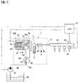
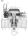
- FIG. 1 is a configuration diagram illustrating a fuel supply system for an internal combustion engine including a high-pressure fuel pump according to a first embodiment of the present invention. It is a longitudinal section showing the high pressure fuel pump concerning a 1st embodiment of the present invention.
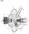
- FIG. 3 is a cross-sectional view of the high-pressure fuel pump according to the first embodiment of the present invention shown in FIG. 2 as seen from the direction of arrows III-III.
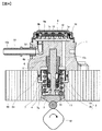
- FIG. 2 is a vertical cross-sectional view showing the high-pressure fuel pump according to the first embodiment of the present invention cut in a plane (a plane different from FIG. 1) including both axes of the plunger and the suction joint.
- FIG. 1 is a configuration diagram illustrating a fuel supply system for an internal combustion engine including a high-pressure fuel pump according to a first embodiment of the present invention. It is a longitudinal section showing the high pressure fuel pump concerning a 1st embodiment of the present invention.
- FIG. 3 is a cross-sectional view of the high-pressure fuel pump according
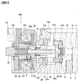
- FIG. 2 is a longitudinal sectional view showing an enlarged state of an electromagnetic suction valve mechanism that constitutes a part of the high-pressure fuel pump according to the first embodiment of the present invention.
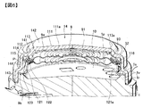
- FIG. 2 is an enlarged perspective view showing a cut-away state of a metal damper and a holding structure that constitute a part of the high-pressure fuel pump according to the first embodiment of the present invention.
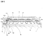
- FIG. 7 is a cross-sectional view illustrating a state after compression (after pressing) of a body-side holding member that forms a part of the high-pressure fuel pump according to the first embodiment of the present invention illustrated in FIG. 6.
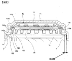
- FIG. 7 is a cross-sectional view illustrating a state before compression (before pressing) of a body-side holding member that forms a part of the high-pressure fuel pump according to the first embodiment of the present invention illustrated in FIG. 6.
- FIG. 1 is a configuration diagram showing a fuel supply system of an internal combustion engine including a high-pressure fuel pump (high-pressure fuel supply pump) of the present embodiment.
- a portion surrounded by a broken line indicates a body 1 (pump body) that is a main body of the high-pressure fuel pump.
- the mechanisms and components shown in the broken lines indicate that they are incorporated in the body 1.
- a fuel supply system includes a fuel tank 20 that stores fuel, a feed pump 21 that pumps up and sends out the fuel in the fuel tank 20, and a pressurized and discharged low-pressure fuel sent from the feed pump 21. It includes a high-pressure fuel pump and a plurality of injectors 24 for injecting high-pressure fuel pumped from the high-pressure fuel pump.
- the high-pressure fuel pump is connected to the feed pump 21 via a suction pipe 28.
- the high-pressure fuel pump pumps fuel to the injector 24 via the common rail 23.
- the injectors 24 are mounted on the common rail 23 according to the number of cylinders of the engine.
- a pressure sensor 26 is mounted on the common rail 23 and detects the pressure of the fuel discharged from the high-pressure fuel pump.
- the high-pressure fuel pump is applied to a so-called direct injection engine system in which the injector 24 directly injects fuel into the cylinder of the engine as an internal combustion engine.
- the high-pressure fuel pump includes a pressurizing chamber 11 for pressurizing the fuel, an electromagnetic suction valve mechanism 300 as a variable capacity mechanism for adjusting the amount of fuel sucked into the pressurizing chamber 11, and reciprocating fuel in the pressurizing chamber 11.
- the plunger 2 includes a plunger 2 that pressurizes by movement, and a discharge valve mechanism 8 that discharges fuel pressurized by the plunger.
- a damper mechanism 9 (metal damper) is provided as a pressure pulsation reduction mechanism for reducing the pressure pulsation generated in the high-pressure fuel pump from spreading to the suction pipe 28.
- the feed pump 21, the electromagnetic suction valve mechanism 300, and the injector 24 are controlled by a control signal output from an engine control unit (hereinafter, referred to as an ECU) 27.
- a detection signal of the pressure sensor 26 is input to the ECU 27.
- the fuel in the fuel tank 20 is pressurized to an appropriate feed pressure by a feed pump 21 driven based on a control signal of an ECU 27, and sent to a low-pressure fuel inlet 10a of a high-pressure fuel pump through a suction pipe 28.
- the fuel that has passed through the low-pressure fuel suction port 10a reaches the suction port 31b of the electromagnetic suction valve mechanism 300 via the damper mechanism 9 and the suction passage 10d.
- the fuel that has passed through the suction valve 30 is sucked into the pressurizing chamber 11 during the downward stroke of the plunger 2 and is pressurized in the pressurizing chamber 11 during the upward stroke of the plunger 2.
- the pressurized fuel is pressure-fed to the common rail 23 via the discharge valve mechanism 8.
- the high-pressure fuel in the common rail 23 is injected into the cylinder of the engine by an injector 24 driven based on a control signal from the ECU 27.
- the high-pressure fuel pump shown in FIG. 1 includes a pressure pulsation propagation prevention mechanism 100 upstream of the damper mechanism 9 (pressure pulsation reduction mechanism).
- the pressure pulsation propagation prevention mechanism 100 includes a valve seat (not shown), a valve 102 that comes into contact with and separates from the valve seat, a spring 103 that urges the valve 102 toward the valve seat, and a spring stopper that limits the stroke of the valve 102. (Not shown). It should be noted that the pressure pulsation propagation preventing mechanism 100 is not shown in drawings other than FIG.
- FIG. 2 is a longitudinal sectional view showing the high-pressure fuel pump according to the present embodiment.
- FIG. 3 is a cross-sectional view of the high-pressure fuel pump shown in FIG.
- FIG. 4 is a longitudinal sectional view showing a state in which the high-pressure fuel pump is cut along a plane including the axes of the plunger and the suction joint (a plane different from FIG. 1).
- FIG. 5 is an enlarged longitudinal sectional view showing an electromagnetic suction valve mechanism constituting a part of the high-pressure fuel pump in an enlarged state. In FIG. 5, a part of the connector is omitted, and the electromagnetic suction valve mechanism is shown in an open state.
- a high-pressure fuel pump includes a body 1 having a pressurizing chamber 11 therein, a plunger 2 attached to the body 1, an electromagnetic suction valve mechanism 300, a discharge valve mechanism 8 (see FIG. 3), and a relief valve mechanism 200. And a damper mechanism 9 as a pressure pulsation reducing mechanism.
- the high-pressure fuel pump is in close contact with the pump mounting portion 80 of the engine using a mounting flange 1e (see FIG. 3) provided at one end of the body 1, and is fixed with a plurality of bolts (not shown). .
- An O-ring 61 is fitted on the outer peripheral surface of the body 1 that fits with the pump mounting portion 80. The O-ring 61 seals between the pump mounting portion 80 and the body 1 to prevent engine oil and the like from leaking out of the engine.
- the body 1 is provided with a stepped first accommodation hole 1 a having a bottom.
- a cylinder 6 for guiding the reciprocating motion of the plunger 2 is press-fitted into the middle diameter portion of the first accommodation hole 1a on the outer peripheral side thereof, and forms a part of the pressure chamber 11 together with the body 1.
- the cylinder 6 is pressed toward the pressurizing chamber 11 by a fixing portion 1f in which a part of the body 1 is deformed to the inner peripheral side, and the end face 6b on the pressurizing chamber 11 side (the upper side in FIGS.
- the pressure of the fuel pressurized in the pressurizing chamber 11 is prevented from leaking to the low-pressure side by being pressed against the wall surface of the first accommodation hole 1a.
- the plunger 2 has a large-diameter portion 2a that slides on the cylinder 6, and a small-diameter portion 2b that extends from the large-diameter portion 2a to the side opposite to the pressurizing chamber 11.
- a tappet 3 is provided on the distal end side (the lower end side in FIGS. 2 and 4) of the small diameter portion 2 b of the plunger 2.
- the tappet 3 converts the rotational motion of a cam 81 (cam mechanism) attached to a camshaft (not shown) of the engine into a linear reciprocating motion and transmits it to the plunger 2.
- the plunger 2 is pressed against the tappet 3 by the urging force of the spring 4 via the retainer 15.
- a seal holder 7 is press-fitted and fixed to the large diameter portion of the first housing hole 1a of the body 1. Inside the seal holder 7, there is formed a sub-chamber 7a for storing fuel leaking from the pressurizing chamber 11 via a sliding portion between the plunger 2 and the cylinder 6.
- a plunger seal 13 is provided on the small diameter portion 2b of the plunger 2.
- the plunger seal 13 is held at the inner peripheral end on the cam 81 side of the seal holder 7 so as to be able to slide on the outer peripheral surface of the small diameter portion 2b.
- the plunger seal 13 seals the fuel in the sub-chamber 7a and prevents the fuel from flowing into the engine when the plunger 2 reciprocates. At the same time, lubricating oil (including engine oil) in the engine is prevented from flowing into the body 1 from the engine side.
- a suction joint 51 is attached to the side surface of the body 1.
- the suction pipe 28 (see FIG. 1) is connected to the suction joint 51, and the fuel from the fuel tank 20 is supplied to the inside of the high-pressure fuel pump through the low-pressure fuel suction port 10 a of the suction joint 51.
- a suction filter 52 is attached downstream of the low-pressure fuel suction port 10a.
- the body 1 is provided with an electromagnetic suction valve mechanism 300 for supplying fuel to the pressurizing chamber 11, as shown in FIGS.
- the electromagnetic suction valve mechanism 300 includes a suction valve section mainly configured by the suction valve 30, a solenoid mechanism section mainly configured by the rod 35 and the anchor section 36, and a solenoid coil 43 mainly. And a coil portion configured as follows.
- the suction valve portion includes a suction valve 30, a suction valve housing 31, a suction valve stopper 32, and a suction valve urging spring 33.
- the suction valve housing 31 includes, for example, a cylindrical valve housing portion 31h that houses the suction valve 30 on one side (the right side in FIG. 5), and an annular suction valve seat portion that protrudes on the inner peripheral side of the valve housing portion 31h. 31a.
- the suction valve housing 31 is formed integrally with a rod guide 37 described later.
- the suction valve housing 31 is provided with a plurality of suction ports 31b radially communicating with a suction passage (low-pressure fuel flow path) 10d.
- a suction valve stopper 32 is press-fitted and fixed to the valve housing portion 31h.
- the suction valve 30 closes by contacting the suction valve seat portion 31a, and contacts the suction valve stopper 32 when the valve is open.
- the suction valve biasing spring 33 is disposed between the suction valve 30 and the suction valve stopper 32, and biases the suction valve 30 in the valve closing direction.
- the solenoid mechanism includes a rod 35 and an anchor 36, which are movable parts, a rod guide 37, an outer core 38, and a fixed core 39, which are fixed parts, a rod urging spring 40, and an anchor part urging spring 41. It is composed of
- the rod 35 is slidably held in the axial direction on the inner peripheral side of the rod guide 37.
- the rod 35 has a distal end on one side (the right side in FIG. 5) that can be brought into contact with and separated from the suction valve 30, and has a rod flange 35a at an end on the other side (the left side in FIG. 5).
- the inner peripheral side of the anchor portion 36 slidably holds the rod 35.
- the anchor portion 36 has a through hole 36a penetrating in the axial direction.
- the rod guide 37 has a cylindrical central bearing portion 37b, and guides the reciprocating operation of the rod 35.
- the rod guide 37 is provided with a through hole 37a penetrating in the axial direction.
- a rod guide 37 is press-fitted on the inner peripheral side on one axial side (the right side in FIG. 5) of the outer core 38.
- An anchor portion 36 is slidably disposed on the inner peripheral side on the other axial side (the left side in FIG. 5).
- the fixed core 39 is disposed such that an end surface on one side (the right side in FIG. 5) faces an end surface of the anchor portion 36 on the rod flange 35a side.
- the one end surface of the fixed core 39 and the end surface of the anchor portion 36 facing the one end surface constitute a magnetic attraction surface S on which a magnetic attraction force acts.
- the rod urging spring 40 between the fixed core 39 and the rod flange 35a applies an urging force in the valve opening direction of the suction valve 30, and keeps the suction valve 30 open when the electromagnetic coil 43 is not energized. I do.
- One end of the anchor portion urging spring 41 is inserted into the central bearing portion 37b of the rod guide 37, and applies an urging force to the anchor portion 36 toward the rod flange 35a.
- the coil portion is composed of a first yoke 42, an electromagnetic coil 43, a second yoke 44, a bobbin 45, and a connector 47 having terminals 46 (see FIG. 2).
- the electromagnetic coil 43 is formed by winding a copper wire around the outer periphery of the bobbin 45, and is attached to the outer periphery of the fixed core 39 and the outer core 38 in a state surrounded by the first yoke 42 and the second yoke 44.
- the first yoke 42 has a hole fixed to the outer peripheral side of the outer core 38.
- the second yoke 44 has a configuration in which the outer peripheral side is fixed to the inner peripheral side of the first yoke 42 and the inner peripheral side is close to the outer periphery of the fixed core 39 with a clearance.
- the discharge valve mechanism 8 on the outlet side of the pressurizing chamber 11 of the body 1 discharges the discharge valve seat 8a, the discharge valve 8b which comes into contact with and separates from the discharge valve seat 8a, and the discharge valve 8b toward the discharge valve seat 8a. It comprises a discharge valve spring 8c to be urged, and a discharge valve stopper 8d for determining the stroke (moving distance) of the discharge valve 8b.
- the discharge valve stopper 8d is held by the plug 8e.
- Plug 8e is joined to body 1 by welding at contact portion 8f.
- a discharge valve chamber 12a is formed on the secondary side of the discharge valve 8b.
- the discharge valve 8b Only when the fuel pressure in the pressurizing chamber 11 becomes higher than the fuel pressure in the discharge valve chamber 12a, the discharge valve 8b opens against the urging force of the discharge valve spring 8c. When the discharge valve 8b is opened, the high-pressure fuel in the pressurizing chamber 11 is discharged to the common rail 23 (see FIG. 1) through the discharge valve chamber 12a, the fuel discharge passage 12b, and the fuel discharge port 12. With the above configuration, the discharge valve mechanism 8 functions as a check valve that restricts the direction of fuel flow.
- the pressurizing chamber 11 includes the body 1, the cylinder 6, the plunger 2, the electromagnetic suction valve mechanism 300, and the discharge valve mechanism 8.
- the discharge joint 60 is attached to the body 1 at a position opposite to the electromagnetic suction valve mechanism 300.
- the discharge joint 60 is formed with a fuel discharge port 12, and the fuel discharge port 12 communicates with the discharge valve chamber 12a via a fuel discharge passage 12b.
- the discharge joint 60 is configured to house the relief valve mechanism 200 therein.
- the relief valve mechanism 200 includes a relief body 201, a relief valve seat 202, a relief valve 203, a relief valve holder 204, and a relief spring 205. After the relief spring 205, the relief valve holder 204, and the relief valve 203 are inserted in this order in the relief body 201, the relief valve seat 202 is press-fitted and fixed.
- the relief spring 205 has one end in contact with the relief body 201 and the other end in contact with the relief valve holder 204.
- the relief valve 203 shuts off the fuel by the urging force of the relief spring 204 acting via the relief valve holder 204 and being pressed by the relief valve seat 202.
- the valve opening pressure of the relief valve 203 is determined by the urging force of the relief spring 205.
- the relief valve mechanism 200 communicates with the pressurizing chamber 11 via a relief passage 210.
- a concave portion 1 p is provided at the tip end side (the upper end side in FIGS. 2 and 4) of the body 1, and has a bottomed cylindrical shape (cup shape).
- the damper cover 14 is fixed to the body 1 by welding so as to cover the recess 1p.
- the recess 1p of the body 1 and the damper cover 14 form a damper chamber 10 (low-pressure fuel chamber).
- the damper chamber 10 communicates with the low-pressure fuel suction port 10a and also communicates with the suction port 31b of the electromagnetic suction valve mechanism 300 via the suction passage 10d. That is, the damper chamber 10 is formed on the upstream side of the pressurizing chamber 11.
- the damper chamber 10 communicates with the sub chamber 7a via a fuel passage 10e.
- a damper mechanism 9 is disposed in the damper chamber 10. That is, the body 1 and the damper cover 14 form a damper chamber 10 in which the damper mechanism 9 is arranged.
- the damper mechanism 9 includes a cover-side holding member 9 a (first holding member) that holds the damper mechanism 9 from the side (upper side) of the damper cover 14 and a body-side holding that holds the damper mechanism 9 from the side (lower side) of the body 1. It is held inside the damper chamber 10 while being sandwiched by the member 9b (second holding member).
- the cover-side holding member 9a is disposed between the damper cover 14 and the damper mechanism 9 in the damper chamber 10, and presses and holds the damper mechanism 9 from one side (the upper side in FIGS. 2 and 4).
- the body-side holding member 9b is arranged in the damper chamber 10 on the opposite side of the cover-side holding member 9a with the damper mechanism 9 interposed therebetween. That is, the body-side holding member 9b is disposed between the body 1 and the damper mechanism 9, and presses and holds the damper mechanism 9 from the other side (the lower side in FIGS. 2 and 4).
- FIG. 6 is an enlarged perspective view showing the damper mechanism and its holding structure in a cut state.
- FIG. 7 is a cross-sectional view illustrating the body-side holding member 9b of the present embodiment after compression (after pressing).
- FIG. 8 is a sectional view showing a state before compression (before pressing) of the body-side holding member 9b constituting a part of the high-pressure fuel pump shown in FIG.
- a damper mechanism 9 is configured such that two corrugated disk-shaped metal diaphragms are welded all around their peripheral edges and adhered to each other, and argon gas is introduced into an internal space formed between the two adhered diaphragms. It is formed by filling an inert gas such as
- the damper mechanism 9 includes a main body 91 having a substantially circular shape in a plan view having an internal space filled with an inert gas, a welded portion 92 formed at a peripheral portion, and extending between the main body 91 and the welded portion 92. And a flat plate portion 93 having an annular shape and a flat shape.
- the flat plate portion 93 is a portion where the planar portions of the two metal diaphragms overlap, and is located radially inward of the welded portion 92.
- the damper mechanism 9 reduces pressure pulsation by increasing or decreasing the volume of the internal space of the main body 91 due to pressure acting on both surfaces.
- the concave portion 1p of the body 1 is formed in a truncated cone shape whose diameter on the opening side is enlarged.
- the outer peripheral surface 1r is formed in a cylindrical shape, and the end surface 1s is formed in an annular shape.
- an annular protrusion 1v is formed at the end of the body 1 on the side of the concave portion 1p.
- the end of the body 1 on the side of the recess 1p and the recess 1p have a rotationally symmetric shape.
- the damper cover 14 is, for example, formed in a stepped cylindrical shape (cup shape) with one side closed and is formed in a rotationally symmetric shape, and includes a cover-side holding member 9a, a damper mechanism 9, and a body-side holding member 9b.
- the components are configured to be accommodated.
- the damper cover 14 includes a cylindrical small-diameter cylindrical portion 141, a circular closing portion 142 that closes one side of the small-diameter cylindrical portion 141, a cylindrical large-diameter cylindrical portion 143 on the opening side, It is composed of a cylindrical medium-diameter tube 144 located between the small-diameter tube 141 and the large-diameter tube 143.
- the damper cover 14 is formed by, for example, pressing a steel plate.
- the large-diameter cylindrical portion 143 of the damper cover 14 is press-fitted into the outer peripheral surface 1r of the end of the body 1 on the concave portion 1p side and fixed by welding.
- the damper cover 14 is arranged on the upstream side of the pressurizing chamber 11 and forms a damper chamber by being attached to the body 1.
- the distal end portion small-diameter cylindrical portion 141 can be made smaller than the portion attached to the body 1 (large-diameter cylindrical portion 143), and the high-pressure fuel can be reduced. This is advantageous when the installation space of the pump is narrow.
- the cover-side holding member 9a is an elastic body having a bottomed cylindrical shape (cup shape) and a rotationally symmetric shape, for example, as shown in FIG.
- the cover-side holding member 9a includes a contact portion 111 that contacts the damper cover 14, an annular pressing portion 112 that presses the flat plate portion 93 of the damper mechanism 9 over the entire circumference, and a contact portion 111.
- the pressing portion 112 are connected to each other, and the cylindrical first side wall surface portion 113 whose diameter increases from the contact portion 111 toward the pressing portion 112, and projects radially outward from the entire circumference of the pressing portion 112 to weld the damper mechanism 9.
- the cover-side holding member 9a is formed, for example, by pressing a steel plate.
- the contact portion 111 is formed in a circular and planar shape.
- a first communication hole 111a is provided at the center of the contact portion 111. In the present invention, a configuration without the first communication hole 111a may be used.
- a plurality of second communication holes 113a are provided in the first side wall 113 at intervals in the circumferential direction.
- the second communication hole 113a is formed in a space (a space surrounded by the cover-side holding member 9a and the damper mechanism 9) formed radially inside the cylindrical first side wall surface portion 113 and a radial direction of the first side wall surface portion 113.
- This is a communication path that communicates with a space formed outside (a space surrounded by the cover-side holding member 9a and the damper cover 14), and fuel inside the damper chamber 10 is supplied to both surfaces of the main body 91 of the damper mechanism 9 on both sides. It functions as a flow path that allows circulation.
- the enclosure 115 is set so that the inner diameter thereof has a gap (first gap) within a predetermined range from the outer diameter of the damper mechanism 9, and the first part restricts the radial movement of the damper mechanism 9. Functions as a regulation unit.
- the first gap between the inner peripheral surface of the enclosure 115 and the peripheral edge of the damper mechanism 9 holds the cover side even if the damper mechanism 9 is displaced in the radial direction with respect to the cover side holding member 9a by the first gap.
- the pressing portion 112 of the member 9a is set in a range where the pressing portion 112 does not contact the welding portion 92 of the damper mechanism 9.
- a plurality of projections 116 projecting outward in the radial direction are provided at the opening end of the enclosure 115 at intervals in the circumferential direction.
- the plurality of protrusions 116 are configured to face the inner peripheral surface of the middle-diameter cylindrical portion 144 of the damper cover 14 with a gap (second gap) within a predetermined range. It functions as a second restricting portion that restricts radial movement of the cover-side holding member 9a.
- the plurality of protrusions 116 have a function of centering the cover-side holding member 9 a in the damper cover 14. In order to sufficiently exhibit the centering function, it is desirable to provide six or more protrusions 116.
- the second gap between the tip of each protrusion 116 and the inner peripheral surface of the middle diameter cylindrical portion 144 of the damper cover 14 is displaced by the cover-side holding member 9a in the radial direction with respect to the damper cover 14 by the second gap. Even so, the pressing portion 112 of the cover-side holding member 9 a is set in a range that does not contact the welded portion 92 of the damper mechanism 9.
- Each protrusion 116 is formed by, for example, cutting and raising, and a space P extending in the circumferential direction is formed between adjacent protrusions 116.
- the space P constitutes a communication path that connects a space on one side (upper side in FIG. 6) of the damper mechanism 9 with a space on the other side (lower side in FIG. 6). It functions as a flow path that allows the fuel to flow on both surfaces of the main body 91 of the damper mechanism 9.
- the length of each protrusion 116 can be set as short as possible in a range where cutting and raising is possible.
- the space P as a flow path can be always secured between the adjacent protrusions 116, so that the cover-side holding member 9a has a size in the radial direction. Miniaturization is possible.
- the body-side holding member 9b is a tubular, rotationally symmetric elastic body as shown in, for example, FIG. 6 (see also FIGS. 7 and 8 described later).
- the body-side holding member 9b includes a cylindrical second side wall surface portion 121 whose one side expands in diameter, and an annular pressing portion bent radially inward from an opening end of the second side wall surface portion 121 on the small diameter side. 122 and an annular flange 123 projecting radially outward from the large-diameter opening end of the second side wall surface 121.
- the body-side holding member 9b is formed, for example, by pressing a steel plate.
- a plurality of third communication holes 121a are provided in the second side wall surface portion 121 at intervals in the circumferential direction.
- the third communication hole 121a is formed in a space (a space surrounded by the body-side holding member 9b, the damper mechanism 9, and the concave portion 1p of the body 1) formed inside the cylindrical second side wall surface portion 121 in the radial direction.
- This is a communication path that communicates with a space (a space surrounded by the body-side holding member 9b and the damper cover 14) formed radially outside the side wall surface portion 121, and the fuel in the damper chamber 10 is supplied to the main body of the damper mechanism 9. It functions as a flow path that allows circulation on both sides of the 91.
- the pressing portion 122 is configured to press the flat plate portion 93 of the damper mechanism 9 over the entire circumference, and is formed to have substantially the same diameter as the pressing portion 122 of the cover-side holding member 9a. That is, the pressing portion 122 of the body-side holding member 9b and the pressing portion 112 of the cover-side holding member 9a are configured to similarly hold both surfaces of the flat plate portion 93 of the damper mechanism 9 respectively.
- the flange portion 123 is configured to abut on the end surface 1s of the body 1 on the side of the concave portion 1p.
- the flange portion 123 is configured to face the inner peripheral surface of the large-diameter cylindrical portion 143 of the damper cover 14 with a gap (third gap) within a predetermined range. It functions as a third regulating portion that regulates the radial movement of the side holding member 9b.
- the flange portion 123 has a function of centering the body-side holding member 9b inside the damper cover 14.
- the third gap between the outer peripheral edge of the flange portion 123 and the inner peripheral surface of the large-diameter cylindrical portion 143 of the damper cover 14 is such that the body-side holding member 9b is radially displaced from the damper cover 14 by the third gap. Even if it does, the pressing portion 122 of the body side holding member 9b is set in a range that does not contact the welded portion 92 of the damper mechanism 9.
- the body-side holding member 9b urges the bottom surface (flange portion 123) contacting the body 1 and the downward direction from the damper cover 14 toward the body 1. And a bending portion 124 formed along the biasing direction.
- the body-side holding member 9b is located on the side of the body 1 with respect to the bottom surface 123 in contact with the body end surface 1s, and on the inner diameter side with respect to the bottom surface 123, and at the contact portion s between the body end surface 1s and the bottom surface 123. It has a bent portion 124 (bent portion) formed by bending. Accordingly, when the cover-side holding member 9a is urged by the damper cover 14, the deformation in the radial direction when the body-side holding member 9b is urged can be reduced, and the member can be bent in the axial direction. Therefore, it is possible to prevent the pressing portion 122 of the body-side holding member 9b from being largely deformed in the radial direction and coming into contact with the welding portion 92 of the damper mechanism 9.
- the body-side holding member 9b has a body-side holding side surface portion 121 that is connected to the bent portion 124 and that faces the damper mechanism 9 with respect to the contact portion s between the body 1 and the bottom surface 123.
- the radial length (the contact width between the body and the body-side holding member 9b in FIG. 8) of the contact portion s in contact with the body-side holding member 9b of the body 1 is configured to be 1.2 mm to 1.6 mm. Is desirable.
- a communication passage communicating the left and right sides of the body-side holding member side surface 121 is formed in the body-side holding member side surface 121 of the body-side holding member 9b.
- the body 1 preferably has a recess 1p on the opposite side of the damper mechanism 9 from the contact portion s that contacts the body-side holding member 9b.
- the contact angle 112 between the contact surface 112a between the cover-side holding member 9a and the damper mechanism 9 and the cover-side holding side surface 113 from the contact surface 112a toward the damper cover 14 is set to 40 ° to 50 °. Is desirable.
- the cover-side holding member 9a is configured to hold the damper mechanism by being pressed toward the damper mechanism 9 by the damper cover 14.
- the damper mechanism 9 is configured by joining two metal diaphragms 91 at the outer peripheral joint portion 92, and the cover-side holding member 9 a is a cover-side holding contact portion that contacts the damper mechanism on the inner diameter side of the outer peripheral joint portion 92. 112a, and a cover-side holding regulating portion 116 whose radial movement is regulated by contacting the cover side surface 144a of the damper cover 14 on the outer diameter side from the outer peripheral joint portion 92. It is desirable that the acute intersection angle ⁇ b between the contact surface 112a and the body-side holding side surface portion 121 is larger than the acute angle intersection angle ⁇ a between the contact surface 112a and the cover-side holding side surface portion 113. With this configuration, deformation in the outer diameter direction can be intentionally stopped.
- the upper end 122 of the body-side holding side surface portion 121 of the body-side holding member 9b be in contact with the damper mechanism 9 on the inner diameter side with respect to the outer peripheral joint portion 92.
- the body-side holding member 9b contacts the cover side surface 143a of the damper cover 14 on the outer diameter side of the outer peripheral joint portion 92, thereby restricting the movement in the outer diameter direction.
- the cover-side holding restricting portion 116 of the cover-side holding member 9a is formed by a projecting portion 116a that protrudes toward the outer diameter side.
- the gap formed by the cover-side holding restricting portion 116 and the projecting portion 116a can be used as a fuel passage communicating vertically.
- the present invention is not necessarily limited to this positional relationship.
- the bending portion 124 of the body-side holding member 9b may be formed by a thin portion that is thinner than other portions of the body-side holding member 124.
- it is desirable that the bending portion 124 of the body-side holding member 9b is formed on the inner diameter side from the bottom surface 1s and below the bottom surface 1s.
- the body-side holding member 9b is easily deformed in the axial direction, and the deformation in the radial direction can be suppressed. It is effective even if the amount of compression in the axial direction changes, and it is possible to allow a margin for defining the amount of deflection at the time of assembly. Therefore, the dimensions of the components in the axial direction can be reduced, and the manufacturing cost of those components can be reduced. It is possible to reduce the manufacturing cost of components for holding the damper mechanism 9 and to suppress deformation of the damper holding members (9a, 9b) in the radial direction during assembly.
- the plunger 2 After the end of the suction stroke, the plunger 2 starts to move upward and moves to the compression stroke.
- the electromagnetic coil 43 is kept in a non-energized state, and no magnetic biasing force is generated.
- the urging force of the rod urging spring 40 keeps the suction valve 30 open.
- the volume of the pressurizing chamber 11 decreases with the compression movement of the plunger 2
- the suction valve 30 when the suction valve 30 is opened, the fuel once drawn into the pressurizing chamber 11 again passes through the opening 30e of the suction valve 30 through the suction passage 30e. Since the pressure is returned to 10d, the pressure in the pressurizing chamber 11 does not increase. This process is called a return process.
- the fuel pressure in the pressurizing chamber 11 rises in accordance with the rising motion of the plunger 2, and when the pressure becomes equal to or higher than the pressure of the fuel discharge port 12, the discharge valve 8b of the discharge valve mechanism 8 shown in FIG. Opens. Accordingly, the high-pressure fuel in the pressurizing chamber 11 is discharged from the fuel discharge port 12 through the discharge valve chamber 12a and the fuel discharge passage 12b, and is supplied to the common rail 23 (see FIG. 1). This process is called a discharge process.
- the compression stroke of the plunger 2 shown in FIG. 2 (the rising stroke between the lower starting point and the upper starting point) includes a return stroke and a discharge stroke. Further, by controlling the timing of energizing the electromagnetic coil 43 of the electromagnetic suction valve mechanism 300, the flow rate of the discharged high-pressure fuel can be controlled.
- the volume of the sub-chamber 7a increases or decreases due to the reciprocating motion of the plunger 2 having the large-diameter portion 2a and the small-diameter portion 2b.
- the volume of the sub-chamber 7a decreases, and fuel flows from the sub-chamber 7a to the damper chamber 10 via the fuel passage 10e.
- the volume of the sub-chamber 7a increases, and fuel flows from the damper chamber 10 to the sub-chamber 7a via the fuel passage 10e.
- the present invention is not limited to the above-described embodiment, but includes various modifications.
- the above embodiments have been described in detail for easy understanding of the present invention, and are not necessarily limited to those having all the described configurations. It is also possible to add, delete, or replace another configuration with respect to a part of the configuration of the embodiment.
- Pressurizing chamber, 92 welding portion, 111: contact portion, 111a: first communication hole (communication hole), 112: holding portion, 113: first side wall surface portion (side wall surface portion), 113a: second communication hole (communication) Hole: 115, Enclosure (first regulating part), 116: Projection (second regulating part), 117: Collar (second regulating part), 117a: Fourth communication hole (flow path), 123: Flange Part (third regulating part), P ... space (flow path)
Landscapes
- Engineering & Computer Science (AREA)
- Mechanical Engineering (AREA)
- General Engineering & Computer Science (AREA)
- Chemical & Material Sciences (AREA)
- Combustion & Propulsion (AREA)
- Fuel-Injection Apparatus (AREA)
Abstract
ボディ側保持部材がダンパ機構9の接合部92へ接触する虞を抑制できる。そのため、本発明の高圧燃料ポンプは、加圧室の上流側に配置され、ボディに取り付けられることでダンパ室を形成するダンパカバーと、前記ダンパ室に配置されるダンパ機構と、前記ダンパ機構を前記ボディの側から保持するボディ側保持部材と、を備え、前記ボディ側保持部材は、前記ボディに接触する底面と、前記ダンパカバーから前記ボディに向かう下方向に付勢されることで付勢方向に沿って形成される撓み部と、を有する。
Description
本発明は、内燃機関用の高圧燃料ポンプに関する。
高圧燃料ポンプでは、ポンプ内で発生した圧力脈動を低減させる圧力脈動低減機構を低圧燃料通路内に形成されたダンパ室に収納したものがある。圧力脈動低減機構を備えた高圧燃料ポンプのなかには、圧力脈動低減機構としての金属ダイアフラムダンパ(金属ダンパ)を低圧燃料通路に組み込む作業の際の部品点数を低減し、部品欠品や誤組立を防ぐようにしたものが知られている(例えば、特許文献1参照)。
特許文献1に記載の高圧燃料ポンプでは、2枚の円盤状金属ダイアフラムを全周にわたって接合して、接合部の内側に密閉空間が形成された金属ダンパを備えており、ダンパの密閉空間にガスが封入されている。さらに、接合部よりも径方向内側の位置で金属ダンパの両外表面にそれぞれ押付け力を付与する一対の押付け部材を有している。これら一対の押付け部材が金属ダンパを挟持した状態で結合されてユニット化されている。
特許文献1に記載の高圧燃料ポンプでは、金属ダンパを挟持した一対の押付け部材(ダンパユニット)を位置決めするために、ポンプ本体の一部を加工する必要があるが、その分、製造コストがかかる。この製造コストを下げるために保持部材側の形状を簡略化し、上下側のダンパ保持部材を設け、これらをダンパカバーとボディで挟み込む構造とすると、ボディ側のダンパ保持部材が変形しダンパに接触する虞がある。ボディ側のダンパ保持部材が金属ダンパに接触すると、金属ダンパに大きな荷重を与える虞がある。
本発明は、上記の問題点を解消するためになされたものであり、その目的は、組み立て時の特にボディ側ダンパ保持部材の径方向への変形を抑制することが可能な高圧燃料ポンプを提供することである。
本願は上記課題を解決する手段を複数含んでいるが、その一例を挙げるならば、加圧室の上流側に配置され、ボディに取り付けられることでダンパ室を形成するダンパカバーと、前記ダンパ室に配置されるダンパ機構と、前記ダンパ機構を前記ボディの側から保持するボディ側保持部材と、を備え、前記ボディ側保持部材は、前記ボディに接触する底面と、前記ダンパカバーから前記ボディに向かう下方向に付勢されることで付勢方向に沿って形成される撓み部と、を有することを特徴とする。
本発明によれば、組み立て時の特にボディ側ダンパ保持部材の径方向への変形を抑制することが可能な高圧燃料ポンプを提供することが可能である。 上記以外の課題、構成及び効果は、以下の実施形態の説明により明らかにされる。
以下、図面を用いて、本発明の高圧燃料ポンプの実施の形態について説明する。なお、各図において、同一符号は同一部分を示す。
(燃料供給システム)
図1は本実施形態の高圧燃料ポンプ(高圧燃料供給ポンプ)を含む内燃機関の燃料供給システムを示す構成図である。図1中、破線で囲まれた部分は、高圧燃料ポンプの本体であるボディ1(ポンプボディ)を示している。この破線の中に示されている機構及び部品は、ボディ1に組み込まれたものであることを示している。
(燃料供給システム)
図1は本実施形態の高圧燃料ポンプ(高圧燃料供給ポンプ)を含む内燃機関の燃料供給システムを示す構成図である。図1中、破線で囲まれた部分は、高圧燃料ポンプの本体であるボディ1(ポンプボディ)を示している。この破線の中に示されている機構及び部品は、ボディ1に組み込まれたものであることを示している。
図1において、燃料供給システムは、燃料を貯留する燃料タンク20と、燃料タンク20内の燃料を汲み上げて送出するフィードポンプ21と、フィードポンプ21から送出された低圧の燃料を加圧して吐出する高圧燃料ポンプと、高圧燃料ポンプから圧送された高圧の燃料を噴射する複数のインジェクタ24とを備えている。高圧燃料ポンプは、吸入配管28を介してフィードポンプ21に接続されている。高圧燃料ポンプは、コモンレール23を介してインジェクタ24に燃料を圧送する。インジェクタ24は、エンジンの気筒数に応じてコモンレール23に装着されている。コモンレール23には、圧力センサ26が装着され、高圧燃料ポンプから吐出された燃料の圧力を検出する。
この高圧燃料ポンプは、インジェクタ24が内燃機関としてエンジンのシリンダ筒内に燃料を直接噴射する、いわゆる直噴エンジンシステムに適用される。高圧燃料ポンプは、燃料を加圧するための加圧室11と、加圧室11に吸入する燃料量を調節する容量可変機構としての電磁吸入弁機構300と、加圧室11内の燃料を往復運動により加圧するプランジャ2と、プランジャにより加圧された燃料を吐出する吐出弁機構8とを備えている。電磁吸入弁機構300の上流側には、高圧燃料ポンプ内で発生した圧力脈動が吸入配管28へ波及することを低減させる圧力脈動低減機構としてのダンパ機構9(金属ダンパ)が設けられている。
フィードポンプ21、電磁吸入弁機構300、インジェクタ24は、エンジンコントロールユニット(以下、ECUという)27の出力する制御信号により制御される。ECU27には、圧力センサ26の検出信号が入力される。
燃料タンク20内の燃料は、ECU27の制御信号に基づき駆動されたフィードポンプ21によって適切なフィード圧力に加圧されて吸入配管28を通して高圧燃料ポンプの低圧燃料吸入口10aに送られる。低圧燃料吸入口10aを通過した燃料は、ダンパ機構9、吸入通路10dを介して電磁吸入弁機構300の吸入ポート31bに至る。吸入弁30を通過した燃料は、プランジャ2の下降行程で加圧室11へ吸入され、プランジャ2の上昇行程で加圧室11内において加圧される。加圧された燃料は、吐出弁機構8を介してコモンレール23へ圧送される。コモンレール23内の高圧の燃料は、ECU27の制御信号に基づき駆動するインジェクタ24によってエンジンのシリンダ筒内へ噴射される。 図1に示す高圧燃料ポンプでは、ダンパ機構9(圧力脈動低減機構)に加え、その上流側に圧力脈動伝播防止機構100を備えている。圧力脈動伝播防止機構100は、弁シート(不図示)と、弁シートに接離する弁102と、弁102を弁シートに向かって付勢するばね103と、弁102のストロークを制限するばねストッパ(不図示)とから構成されている。なお、図1以外の図面には、圧力脈動伝播防止機構100を表示していない。
(高圧燃料ポンプ)
次に高圧燃料ポンプの各部の構成を図2~図5を用いて説明する。
次に高圧燃料ポンプの各部の構成を図2~図5を用いて説明する。
図2は本実施形態に係る高圧燃料ポンプを示す縦断面図である。図3は図2に示す高圧燃料ポンプをIII-III矢視から見た横断面図である。図4は高圧燃料ポンプをプランジャ及び吸入ジョイントの両軸心を含む平面(図1とは異なる平面)で切断した状態で示す縦断面図である。図5は高圧燃料ポンプの一部を構成する電磁吸入弁機構を拡大した状態で示す縦断面図である。なお、図5は、コネクタの一部を省略して示しており、電磁吸入弁機構を開弁状態で図示している。
図2において、高圧燃料ポンプは、内部に加圧室11を有するボディ1と、ボディ1に組み付けられたプランジャ2、電磁吸入弁機構300、吐出弁機構8(図3参照)、リリーフ弁機構200と、圧力脈動低減機構としてのダンパ機構9とを備えている。高圧燃料ポンプは、ボディ1の一方側の端部に設けられた取付フランジ1e(図3参照)を用いてエンジンのポンプ取付部80に密着し、複数のボルト(図示せず)で固定される。ボディ1のポンプ取付部80と嵌合する外周面には、Oリング61が嵌め込まれている。Oリング61は、ポンプ取付部80とボディ1との間をシールし、エンジンオイル等がエンジンの外部に漏れることを防止する。
ボディ1には、図2及び図4に示すように、有底で段付きの第1収容穴部1aが設けられている。第1収容穴部1aの中径部には、プランジャ2の往復運動をガイドするシリンダ6がその外周側において圧入され、ボディ1と共に加圧室11の一部を形成している。シリンダ6を、ボディ1の一部を内周側に変形させた固定部1fにより加圧室11側へ押圧し、加圧室11側(図2及び図4中、上側)の端面6bをボディ1の第1収容穴部1aの壁面に圧着することで、加圧室11内で加圧された燃料が低圧側に漏れないようシールしている。
プランジャ2は、シリンダ6に滑合する大径部2aと、大径部2aから加圧室11とは反対側に延在する小径部2bとを有している。プランジャ2の小径部2bの先端側(図2及び図4中、下端側)には、タペット3が設けられている。タペット3は、エンジンのカムシャフト(図示せず)に取り付けたカム81(カム機構)の回転運動を直線的な往復運動に変換してプランジャ2に伝達するものである。プランジャ2は、リテーナ15を介してばね4の付勢力によりタペット3に圧着されている。
ボディ1の第1収容穴部1aの大径部には、シールホルダ7が圧入固定されている。シールホルダ7の内部には、プランジャ2とシリンダ6の摺動部を介して加圧室11から漏れ出る燃料を貯めておく副室7aが形成されている。
プランジャ2の小径部2bには、プランジャシール13が設置されている。プランジャシール13は、小径部2bの外周面に摺接可能な状態でシールホルダ7のカム81側の内周端部に保持されている。プランジャシール13は、プランジャ2の往復運動時に、副室7a内の燃料をシールしエンジン内部へ流入するのを防止する。同時に、エンジン内の潤滑油(エンジンオイルを含む)がエンジン側からボディ1の内部へ流入するのを防止する。
また、図3及び図4に示すように、ボディ1の側面部には、吸入ジョイント51が取り付けられている。吸入ジョイント51には吸入配管28(図1参照)が接続され、燃料タンク20からの燃料が吸入ジョイント51の低圧燃料吸入口10aを介して高圧燃料ポンプの内部へ供給される。低圧燃料吸入口10aの下流側には、吸入フィルタ52が取り付けられている。
ボディ1には、図2及び図3に示すように、燃料を加圧室11に供給するための電磁吸入弁機構300が設置されている。電磁吸入弁機構300は、図5に示すように、吸入弁30を主体に構成された吸入弁部と、ロッド35とアンカー部36を主体に構成されたソレノイド機構部と、電磁コイル43を主体に構成されたコイル部とに大別される。
吸入弁部は、吸入弁30、吸入弁ハウジング31、吸入弁ストッパ32、吸入弁付勢ばね33とからなる。吸入弁ハウジング31は、例えば、一方側(図5中、右側)に吸入弁30を収容する筒状の弁収容部31hと、弁収容部31hの内周側に張り出した環状の吸入弁シート部31aとを有している。吸入弁ハウジング31は、後述のロッドガイド37と一体に成形されている。吸入弁ハウジング31には、吸入通路(低圧燃料流路)10dに連通する吸入ポート31bが放射状に複数設けられている。弁収容部31hには、吸入弁ストッパ32が圧入固定されている。吸入弁30は、吸入弁シート部31aと当接することにより閉弁し、開弁時には吸入弁ストッパ32と当接する。吸入弁付勢ばね33は、吸入弁30と吸入弁ストッパ32との間に配置され、吸入弁30を閉弁方向に付勢している。
ソレノイド機構部は、可動部であるロッド35及びアンカー部36と、固定部であるロッドガイド37、アウターコア38、及び固定コア39と、さらに、ロッド付勢ばね40と、アンカー部付勢ばね41とで構成されている。
ロッド35は、ロッドガイド37の内周側で軸方向に摺動自在に保持されている。ロッド35は、一方側(図5中、右側)の先端部が吸入弁30に接離可能で、他方側(図5中、左側)の端部にロッドつば部35aを有している。アンカー部36は、その内周側がロッド35を摺動自在に保持している。アンカー部36は、軸方向に貫通する貫通穴36aを有する。
ロッドガイド37は、円筒形状の中央軸受部37bを有しており、ロッド35の往復動作をガイドする。ロッドガイド37には、軸方向に貫通する貫通穴37aが設けられている。アウターコア38の軸方向一方側(図5中、右側)の内周側には、ロッドガイド37が圧入嵌合されている。軸方向他方側(図5中、左側)の内周側には、アンカー部36が摺動可能に配置されている。固定コア39は、一方側(図5中、右側)の端面がアンカー部36のロッドつば部35a側の端面と対向するように配置されている。固定コア39の一方側端面とそれに対向するアンカー部36の端面は、相互間に磁気吸引力が作用する磁気吸引面Sを構成する。吸入弁30が開弁状態のときには、相互間に磁気空隙を介して対面している。
固定コア39とロッドつば部35aとの間のロッド付勢ばね40は、吸入弁30の開弁方向に付勢力を与えるものであり、電磁コイル43が無通電状態において吸入弁30を開弁維持する。アンカー部付勢ばね41は、一方側の端部がロッドガイド37の中央軸受部37bに挿入され、アンカー部36にロッドつば部35a側への付勢力を与える。
コイル部は、第1ヨーク42、電磁コイル43、第2ヨーク44、ボビン45、端子46(図2参照)を有するコネクタ47から構成されている。電磁コイル43は、ボビン45の外周に銅線を巻いたものであり、第1ヨーク42と第2ヨーク44により取り囲まれた状態で、固定コア39及びアウターコア38の外周側に組み付けられている。第1ヨーク42は、その孔部がアウターコア38の外周側に固定されている。第2ヨーク44は、外周側が第1ヨーク42の内周側に固定され、内周側が固定コア39の外周とクリアランスを以って近接する構成である。
アウターコア38、第1ヨーク42、第2ヨーク44、固定コア39、アンカー部36により形成される磁気回路では、電磁コイル43に電流を与えると、固定コア39とアンカー部36と間に磁気吸引力が発生する。
また、ボディ1の加圧室11出口側の吐出弁機構8は(図3)、吐出弁シート8a、吐出弁シート8aと接離する吐出弁8b、吐出弁8bを吐出弁シート8aに向かって付勢する吐出弁ばね8c、吐出弁8bのストローク(移動距離)を決める吐出弁ストッパ8dから構成される。吐出弁ストッパ8dは、プラグ8eに保持されている。プラグ8eをボディ1に当接部8fで溶接により接合される。吐出弁8bの二次側には、吐出弁室12aが形成されている。
加圧室11の燃料圧力が吐出弁室12aの燃料圧力よりも大きくなった時に初めて、吐出弁8bは吐出弁ばね8cの付勢力に逆らって開弁する。吐出弁8bが開弁すると、加圧室11内の高圧の燃料は吐出弁室12a、燃料吐出通路12b、燃料吐出口12を経てコモンレール23(図1参照)へ吐出される。以上のような構成により、吐出弁機構8は、燃料の流通方向を制限する逆止弁として機能する。
なお、加圧室11は、ボディ1、シリンダ6、プランジャ2、電磁吸入弁機構300、吐出弁機構8にて構成されている。
また、図2及び図3に示すように、ボディ1における電磁吸入弁機構300とは反対側の位置に、吐出ジョイント60が取り付けられている。吐出ジョイント60には燃料吐出口12が形成されており、燃料吐出口12は燃料吐出通路12bを介して吐出弁室12aと連通している。吐出ジョイント60は、その内部にリリーフ弁機構200を収容するように構成されている。
リリーフ弁機構200は、リリーフボディ201、リリーフ弁シート202、リリーフ弁203、リリーフ弁ホルダ204、リリーフばね205からなる。リリーフボディ201内には、リリーフばね205、リリーフ弁ホルダ204、リリーフ弁203の順に挿入された後、リリーフ弁シート202が圧入固定されている。リリーフばね205は、一端側がリリーフボディ201に当接し、他端側がリリーフ弁ホルダ204に当接している。リリーフ弁203は、リリーフばね204の付勢力がリリーフ弁ホルダ204を介して作用してリリーフ弁シート202に押圧されることで燃料を遮断する。リリーフ弁203の開弁圧力は、リリーフばね205の付勢力によって決定される。リリーフ弁機構200は、リリーフ通路210を介して加圧室11に連通している。
また、図2及び図4に示すように、ボディ1の先端部側(図2及び図4中、上端部側)には、凹部1pが設けられており、有底筒状(カップ状)のダンパカバー14が凹部1pを覆うようにボディ1に溶接により固定されている。ボディ1の凹部1pとダンパカバー14とにより、ダンパ室10(低圧燃料室)が形成されている。ダンパ室10は、低圧燃料吸入口10aに連通すると共に、吸入通路10dを介して電磁吸入弁機構300の吸入ポート31bに連通している。すなわち、ダンパ室10は、加圧室11の上流側に形成されている。また、ダンパ室10は、燃料通路10eを介して副室7aに連通している。
ダンパ室10には、ダンパ機構9が配置されている。すなわち、ボディ1とダンパカバー14とにより、ダンパ機構9が配置されるダンパ室10が形成されている。ダンパ機構9は、ダンパ機構9をダンパカバー14の側(上側)から保持するカバー側保持部材9a(第1保持部材)とダンパ機構9をボディ1の側(下側)から保持するボディ側保持部材9b(第2保持部材)とにより挟持された状態でダンパ室10の内部に保持されている。カバー側保持部材9aは、ダンパ室10におけるダンパカバー14とダンパ機構9との間に配置され、ダンパ機構9を一方側(図2及び図4中、上側)から押圧して保持している。ボディ側保持部材9bは、ダンパ室10においてダンパ機構9を挟んでカバー側保持部材9aの反対側にボディ配置される。つまり、ボディ側保持部材9bは、ボディ1とダンパ機構9との間に配置され、ダンパ機構9を他方側(図2及び図4中、下側)から押圧して保持している。
(ダンパ機構及びダンパ機構の保持構造の詳細) 次に、ダンパ機構9及びダンパ機構9を保持するための部品の構成・構造の詳細を図6及び図7を用いて説明する。図6はダンパ機構及びその保持構造を切断した状態で示す拡大斜視図である。図7は本実施形態のボディ側保持部材9bの圧縮後(押圧後)を示す断面図である。図8は図6に示す高圧燃料ポンプの一部を構成するボディ側保持部材9bの圧縮前(押圧前)を示す断面図である。
図6において、ダンパ機構9は、例えば、2枚の波板状の円盤型金属ダイアフラムをその周縁部で全周溶接して張り合わせ、張り合わせた2枚のダイアフラムの間に形成された内部空間にアルゴン等の不活性ガスを封入することで形成されている。ダンパ機構9は、不活性ガスが封入された内部空間を有する平面視略円形状の本体部91と、周縁部に形成された溶接部92と、本体部91と溶接部92との間に延在する環状且つ平面状の平板部93とで構成されている。平板部93は、2枚の金属ダイアフラムの平面状の部分が重なり合っている部分であり、溶接部92よりも径方向内側に位置している。ダンパ機構9は、両面に作用する圧力によって本体部91の内部空間の容積が増減することで、圧力脈動を低減する。
ボディ1の凹部1pは、開口側が拡径する円錐台状に形成されている。ボディ1の凹部1p側の端部は、外周面1rが円柱面状に形成され、端面1sが円環状に形成されている。換言すると、ボディ1の凹部1p側の端部には、環状突部1vが形成されている。ボディ1の凹部1p側の端部及び凹部1pは、回転対称な形状である。
ダンパカバー14は、例えば、一方側が閉塞された段付きの筒状(カップ状)で回転対称な形状に形成されており、カバー側保持部材9a、ダンパ機構9、ボディ側保持部材9bの3つの部品を収容可能に構成されている。具体的には、ダンパカバー14は、円筒状の小径筒部141と、小径筒部141の一方側を閉塞する円形状の閉塞部142と、開口側の円筒状の大径筒部143と、小径筒部141と大径筒部143の間に位置する円筒状の中径筒部144とで構成されている。
ダンパカバー14は、例えば、鋼板をプレス加工することで成形したものである。ダンパカバー14の大径筒部143は、ボディ1の凹部1p側の端部の外周面1rに圧入され溶接により固定される。ダンパカバー14は加圧室11の上流側に配置され、ボディ1に取り付けられることでダンパ室を形成する。ダンパカバー14は、筒状部分に複数の段を設けることで、ボディ1に取り付ける部分(大径筒部143)に対して先端部分(小径筒部141)を小型化することができ、高圧燃料ポンプの設置空間が狭隘な場合に有利である。
カバー側保持部材9aは、例えば図6に示すように、有底筒状(カップ状)で回転対称な形状の弾性体である。具体的には、カバー側保持部材9aは、ダンパカバー14に当接する当接部111と、ダンパ機構9の平板部93を全周に亘って押圧する環状の押え部112と、当接部111と押え部112とを繋ぎ、当接部111から押え部112へ向かって拡径する筒状の第1側壁面部113と、押え部112の全周から径方向外側に突出し、ダンパ機構9の溶接部92の一部を受け容れ可能に湾曲する環状の湾曲部114と、湾曲部114から軸方向に延在し、ダンパ機構9の周縁部を取り囲む円筒状の囲い部115とを有している。カバー側保持部材9aは、例えば、鋼板をプレス加工することで成形したものである。
当接部111は、円形状且つ平面状に形成されている。当接部111の中央部には、第1連通孔111aが設けられている。本発明は、第1連通孔111aを設けない構成でも構わない。
第1側壁面部113には、第2連通孔113aが周方向に間隔をあけて複数設けられている。第2連通孔113aは、筒状の第1側壁面部113の径方向内側に形成された空間(カバー側保持部材9aとダンパ機構9とで囲まれた空間)と第1側壁面部113の径方向外側に形成された空間(カバー側保持部材9aとダンパカバー14とで囲まれた空間)とを連通する連通路であり、ダンパ室10の内部の燃料がダンパ機構9の本体部91の両面に流通することを可能とする流路として機能する。
囲い部115は、その内径がダンパ機構9の外径よりも所定の範囲内の間隙(第1間隙)をもつように設定されており、ダンパ機構9の径方向への移動を規制する第1規制部として機能する。囲い部115の内周面とダンパ機構9の周縁との間の第1間隙は、ダンパ機構9がカバー側保持部材9aに対して径方向に当該第1間隙分ずれたとしても、カバー側保持部材9aの押え部112がダンパ機構9の溶接部92に接触しない範囲に設定されている。
囲い部115の開口側端部には、径方向外側に突出する突起部116が周方向に間隔をあけて複数設けられている。複数の突起部116は、ダンパカバー14の中径筒部144の内周面に対して所定の範囲内の間隙(第2間隙)をもって対向するように構成されており、ダンパ室10内でのカバー側保持部材9aの径方向の移動を規制する第2規制部として機能する。換言すると、複数の突起部116は、ダンパカバー14内でのカバー側保持部材9aの芯出し機能を有している。当該芯出し機能を十分に発揮するためには、6つ以上の突起部116を設けることが望ましい。各突起部116の先端とダンパカバー14の中径筒部144の内周面との間の第2間隙は、カバー側保持部材9aがダンパカバー14に対して径方向に当該第2間隙分ずれたとしても、カバー側保持部材9aの押え部112がダンパ機構9の溶接部92に接触しない範囲に設定されている。
各突起部116は例えば切り起こしによって成形されており、隣接する突起部116の間には、周方向に延在する空間Pが形成されている。この空間Pは、ダンパ機構9の一方側(図6中、上側)の空間と他方側(図6中、下側)の空間を連通させる連通路を構成しており、ダンパ室10の内部の燃料がダンパ機構9の本体部91の両面に流通することを可能とする流路として機能する。各突起部116の長さは、切り起こしが可能な範囲で短く設定することが可能である。突起部116の長さを極力短くした場合でも、隣接する突起部116の間に流路としての空間Pを必ず確保することができるので、カバー側保持部材9aは、その径方向の大きさの小型化が可能である。
ボディ側保持部材9bは、例えば図6(後述の図7、8も参照)に示すように、筒状で回転対称な形状の弾性体である。具体的には、ボディ側保持部材9bは、一方側が拡径する筒状の第2側壁面部121と、第2側壁面部121の小径側の開口端部から径方向内側に屈曲する環状の押え部122と、第2側壁面部121の大径側の開口端部から径方向外側に突出する環状のフランジ部123とで構成されている。ボディ側保持部材9bは、例えば、鋼板をプレス加工することで成形したものである。
第2側壁面部121には、第3連通孔121aが周方向に間隔をあけて複数設けられている。第3連通孔121aは、筒状の第2側壁面部121の径方向内側に形成された空間(ボディ側保持部材9bとダンパ機構9とボディ1の凹部1pとで囲まれた空間)と第2側壁面部121の径方向外側に形成された空間(ボディ側保持部材9bとダンパカバー14とで囲まれた空間)とを連通する連通路であり、ダンパ室10の燃料がダンパ機構9の本体部91の両面に流通することを可能とする流路として機能する。
押え部122は、ダンパ機構9の平板部93を全周に亘って押圧するように構成されており、カバー側保持部材9aの押え部122と略同じ径に形成されている。すなわち、ボディ側保持部材9bの押え部122及びカバー側保持部材9aの押え部112は、ダンパ機構9の平板部93の両面をそれぞれ同じように挟持するように構成されている。
フランジ部123は、ボディ1の凹部1p側の端面1sに当接するように構成されている。また、フランジ部123は、ダンパカバー14の大径筒部143の内周面に対して所定の範囲内の間隙(第3間隙)をもって対向するように構成されており、ダンパ室10でのボディ側保持部材9bの径方向の移動を規制する第3規制部として機能する。換言すると、フランジ部123は、ダンパカバー14内でのボディ側保持部材9bの芯出し機能を有している。フランジ部123の外周縁とダンパカバー14の大径筒部143の内周面との間の第3間隙は、ボディ側保持部材9bがダンパカバー14に対して径方向に当該第3間隙分ずれたとしても、ボディ側保持部材9bの押え部122がダンパ機構9の溶接部92に接触しない範囲に設定されている。
ただし、ボディ側保持部材9bの押え部122がダンパ機構9の溶接部92に接触しない範囲に寸法を設定した場合でも、組み立て途中でボディ側保持部材9bが径方向に変形しダンパ機構9に接触する可能性がある。これを回避するために本実施形態では、図7に示すようにボディ側保持部材9bは、ボディ1に接触する底面(フランジ部123)と、ダンパカバー14からボディ1に向かう下方向に付勢されることで付勢方向に沿って形成される撓み部124と、を有する。
より具体的にはボディ側保持部材9bはボディ端面1sに接触する底面123と、底面123に対し内径側に位置するとともにボディ端面1sと底面123との接触部sに対し、ボディ1の側に曲がって形成される曲がり部124(撓み部)を有する。これによりダンパカバー14によりカバー側保持部材9aが付勢されることでボディ側保持部材9bが付勢される際に径方向への変形を少なくし軸方向に撓むようにすることができる。よってボディ側保持部材9bの押え部122が径方向に大きく変形し、ダンパ機構9の溶接部92への接触することを回避できる。
この場合、ボディ側保持部材9bは、曲がり部124と繋がるとともにボディ1と底面123との接触部sに対し、ダンパ機構9の側に向かうボディ側保持側面部121を有している。また、ボディ1のボディ側保持部材9bと接触する接触部sの径方向長さ(図8のボディとボディ側保持部材9bの接触幅)が1.2mm~1.6mmとなるように構成されることが望ましい。この場合、ボディ側保持部材9bのボディ側保持部材側面部121にボディ側保持部材側面部121の左右を連通する連通路を形成されることが望ましい。これによりダンパ機構の下面に燃料を充満させることができ、圧力脈動低減効果を得るようにすることができる。またボディ1はボディ側保持部材9bと接触する接触部sからダンパ機構9と反対側に凹み部1pを有することが望ましい。
またカバー側保持部材9aとダンパ機構9との接触面112aと、接触面112aからダンパカバー14に向かうカバー側保持側面113との鋭角の交差角度θaが40°~50°となるように構成されることが望ましい。
この時、カバー側保持部材9aはダンパカバー14によりダンパ機構9に向かって押し付けられることによりダンパ機構を保持するように構成される。
またダンパ機構9は、2枚の金属ダイアフラム91が外周接合部92において接合されることで構成され、カバー側保持部材9aは外周接合部92より内径側においてダンパ機構と接触するカバー側保持接触部112aと、外周接合部92より外径側においてダンパカバー14のカバー側面144aと接触することで径方向の動きが規制されるカバー側保持規制部116を有する。なお、接触面112aとボディ側保持側面部121との鋭角の交差角度θbが接触面112aとカバー側保持側面部113との鋭角の交差角度θaよりも大きく構成されることが望ましい。このように構成することで外径方向への変形を意図的に止めることができる。
この時、ボディ側保持部材9bのボディ側保持側面部121の上端部122が外周接合部92に対し内径側においてダンパ機構9と接触する構成とすることが望ましい。ボディ側保持部材9bは、外周接合部92より外径側においてダンパカバー14のカバー側面143aと接触することで外径方向の動きが規制される。
また、カバー側保持部材9aのカバー側保持規制部116は外径側に突出する突出部116aにより形成されることが望ましい。カバー側保持規制部116と突出部116aにより形成される隙間を上下を連通する燃料通路として利用することができる。
カバー側保持部材9aの突出部116aにカバー側保持部材9bの上下を連通する複数の貫通孔が形成しても流路を形成することができるため同様の効果が得られる。
以上では、撓み部124(曲がり部)が底面1s、又は接触部sに対して下側に位置する構成について説明したが、本発明は必ずしもこの位置関係には限定されない。たとえばボディ側保持部材9bの撓み部124は、ボディ側保持部材124の他の部位の厚さよりも薄い薄肉部により形成されても良い。但し、ボディ側保持部材9bの撓み部124は、底面1sよりも内径側で、かつ、底面1sよりも下方向において形成されることが望ましい。
以上の通り、本実施例によれば、ボディ側保持部材9bが軸方向に変形しやすくなり、径方向の変形を抑制できる。それは軸方向の圧縮量が変わっても効果があり組立時のたわみ量規定に余裕を持たせることができる。したがって軸方向の部品寸法緩和が可能となり、それら部品の製造コストを低減することが可能である。ダンパ機構9を保持するための部品の製造コストを低減し、組み立て時のダンパ保持部材(9a,9b)の径方向への変形を抑制することが可能となる。
(高圧燃料ポンプの動作)
図2に示すカム81の回転によりプランジャ2がカム81側に移動して吸入行程の状態にある時は、加圧室11の容積が増加し、加圧室11内の燃料圧力が低下する。この行程で加圧室11内の燃料圧力が吸入ポート31bの圧力よりも低くなると、吸入弁30が開口状態になる。このため、燃料は、図5に示すように、吸入弁30の開口部30eを通り加圧室11に流入する。
図2に示すカム81の回転によりプランジャ2がカム81側に移動して吸入行程の状態にある時は、加圧室11の容積が増加し、加圧室11内の燃料圧力が低下する。この行程で加圧室11内の燃料圧力が吸入ポート31bの圧力よりも低くなると、吸入弁30が開口状態になる。このため、燃料は、図5に示すように、吸入弁30の開口部30eを通り加圧室11に流入する。
プランジャ2は、吸入行程の終了後、上昇運動に転じ圧縮行程に移る。ここで、電磁コイル43は無通電状態が維持されたままであり、磁気付勢力は生じていない。この場合、ロッド付勢ばね40の付勢力により、吸入弁30が開弁状態で維持されている。加圧室11の容積はプランジャ2の圧縮運動に伴い減少するが、吸入弁30が開弁した状態では、加圧室11に一度吸入された燃料が再び吸入弁30の開口部30eを通して吸入通路10dへと戻されるので、加圧室11の圧力が上昇することは無い。この行程を戻し行程と称する。
この状態で、ECU27(図1参照)の制御信号を電磁吸入弁機構300に印加すると、電磁コイル43には端子46(図2参照)を介して電流が流れる。すると、固定コア39とアンカー部36との間に磁気吸引力が作用し、これにより磁気付勢力がロッド付勢ばね40の付勢力に打ち勝ってロッド35が吸入弁30から離れる方向に移動する。このため、吸入弁付勢ばね33の付勢力及び燃料の吸入通路10dへの流れ込みによる流体力によって吸入弁30が閉弁する。吸入弁30の閉弁により、加圧室11の燃料圧力は、プランジャ2の上昇運動に応じて上昇し、燃料吐出口12の圧力以上になると、図3に示す吐出弁機構8の吐出弁8bが開弁する。これにより、加圧室11の高圧の燃料は、吐出弁室12a、燃料吐出通路12bを通って燃料吐出口12から吐出され、コモンレール23(図1参照)へ供給される。この行程を吐出行程と称する。
すなわち、図2に示すプランジャ2の圧縮行程(下始点から上始点までの間の上昇行程)は、戻し行程と吐出行程からなる。また、電磁吸入弁機構300の電磁コイル43への通電タイミングを制御することで、吐出される高圧燃料の流量を制御することができる。
戻し行程において加圧室11に一度流入した燃料が開弁状態の吸入弁30を通して再び吸入通路10dへ戻される場合、加圧室11から吸入通路10dへの燃料の逆流によって、ダンパ室10に圧力脈動が発生する。圧力脈動は、図6に示すダンパ室10に配置されたダンパ機構9のボディ1側(図6中、下側)の面に伝達されると共に、ボディ側保持部材9bの第3連通孔121a、カバー側保持部材9aの隣接する突起部116間の空間P、カバー側保持部材9aの第2連通孔113aを順に介して、ダンパ機構9のダンパカバー14側(図6中、上側)の面に伝達される。この圧力脈動は、ダンパ機構9の本体部91が膨張及び収縮することによって吸収低減される。
また、図4に示すように、大径部2aと小径部2bとを有するプランジャ2の往復運動によって、副室7aの体積が増減する。プランジャ2の下降時は、副室7aの体積が減少し、副室7aから燃料通路10eを介してダンパ室10への燃料の流れが発生する。一方上昇時は、副室7aの体積が増加し、ダンパ室10から燃料通路10eを介して副室7aへの燃料の流れが発生する。これにより、ポンプの吸入行程又は戻し行程におけるポンプ内外への燃料流量を低減することができ、ポンプ内部で発生する圧力脈動を低減することができる。
なお、本発明は上述した実施の形態に限られるものではなく、様々な変形例が含まれる。上記した実施形態は本発明をわかり易く説明するために詳細に説明したものであり、必ずしも説明した全ての構成を備えるものに限定されるものではない。実施形態の構成の一部について、他の構成の追加、削除、置換をすることも可能である。
1…ボディ、14、14A、14B…ダンパカバー、9…ダンパ機構(金属ダンパ)、 9a、9c…カバー側保持部材、 9b…ボディ側保持部材、10…低圧燃料室(ダンパ室)、11…加圧室、92…溶接部、111…当接部、111a…第1連通孔(連通孔)、112…押え部、113…第1側壁面部(側壁面部)、113a…第2連通孔(連通孔)、115…囲い部(第1規制部)、116…突起部(第2規制部)、117…つば部(第2規制部)、117a…第4連通孔(流路)、123…フランジ部(第3規制部)、P…空間(流路)
Claims (15)
- 加圧室の上流側に配置され、ボディに取り付けられることでダンパ室を形成するダンパカバーと、
前記ダンパ室に配置されるダンパ機構と、
前記ダンパ機構を前記ボディの側から保持するボディ側保持部材と、を備え、
前記ボディ側保持部材は、前記ボディに接触する底面と、前記ダンパカバーから前記ボディに向かう下方向に付勢されることで付勢方向に沿って形成される撓み部と、を有する高圧燃料ポンプ。 - 加圧室の上流側に配置され、ボディに取り付けられることでダンパ室を形成するダンパカバーと、
前記ダンパ室に配置されるダンパ機構と、
前記ダンパ機構を前記ボディの側から保持するボディ側保持部材と、を備え、
前記ボディ側保持部材は、前記ボディに接触する底面と、前記底面に対し内径側に位置するとともに前記ボディと前記底面との接触部に対し、前記ボディの側に曲がって形成される曲がり部と、を有する高圧燃料ポンプ。 - 加圧室の上流側に配置され、ボディに取り付けられることでダンパ室を形成するダンパカバーと、
前記ダンパ室に配置されるダンパ機構と、
前記ダンパ機構を前記ダンパカバーの側から保持するカバー側保持部材と、を備え、
前記カバー側保持部材と前記ダンパ機構との接触面と、前記接触面から前記ダンパカバーに向かうカバー側保持側面との交差角度が40°~50°となるように構成された高圧燃料ポンプ。 - 請求項3に記載の高圧燃料ポンプにおいて、
前記カバー側保持部材は前記ダンパカバーにより前記ダンパ機構に向かって押し付けられることにより前記ダンパ機構を保持するように構成された高圧燃料ポンプ。 - 請求項3に記載の高圧燃料ポンプにおいて、
前記ダンパ機構は、2枚の金属ダイアフラムが外周接合部において接合されることで構成され、
前記カバー側保持部材は、前記外周接合部より内径側において前記ダンパ機構と接触するカバー側保持接触部と、前記外周接合部より外径側において前記ダンパカバーのカバー側面と接触することで径方向の動きが規制されるカバー側保持規制部と、を有する高圧燃料ポンプ。 - 請求項5に記載の高圧燃料ポンプにおいて、
前記カバー側保持部材の前記カバー側保持規制部は外径側に突出する突出部により形成される高圧燃料ポンプ。 - 請求項6に記載の高圧燃料ポンプにおいて、
前記カバー側保持部材の前記突出部同士に前記カバー側保持部材の上下を連通する複数の貫通孔が形成される高圧燃料ポンプ。 - 請求項2に記載の高圧燃料ポンプにおいて、
前記ボディ側保持部材は、前記曲がり部と繋がるとともに前記ボディと前記底面との接触部に対し、前記ダンパ機構の側に向かうボディ側保持側面部を有する高圧燃料ポンプ。 - 請求項2に記載の高圧燃料ポンプにおいて、
前記ボディの前記ボディ側保持部材と接触する前記接触部の径方向長さ(※座面幅)が1.2mm~1.6mmとなるように構成された高圧燃料ポンプ。 - 請求項9に記載の高圧燃料ポンプにおいて、
前記ボディは前記ボディ側保持部材と接触する前記接触部から前記ダンパ機構と反対側に凹む凹み部を有する高圧燃料ポンプ。 - 請求項8に記載の高圧燃料ポンプにおいて、
前記ダンパ機構は、2枚の金属ダイアフラムが外周接合部において接合されることで構成され、
前記ボディ側保持部材の前記ボディ側保持側面部の上端部が前記外周接合部に対し内径側において前記ダンパ機構と接触する高圧燃料ポンプ。 - 請求項11に記載の高圧燃料ポンプにおいて、
前記ボディ側保持部材は、前記外周接合部より外径側において前記ダンパカバーのカバー側面と接触することで径方向の動きが規制されるボディ側保持規制部と、を有する高圧燃料ポンプ。 - 請求項8に記載の高圧燃料ポンプにおいて、
前記ボディ側保持部材の前記ボディ側保持側面部に前記ボディ側保持側面部の左右を連通する連通路が形成される高圧燃料ポンプ。 - 請求項1に記載の高圧燃料ポンプにおいて、
前記ボディ側保持部材の前記撓み部は、前記ボディ側保持部材の他の部位の厚さよりも薄い薄肉部により形成される高圧燃料ポンプ。 - 請求項1に記載の高圧燃料ポンプにおいて、
前記ボディ側保持部材の前記撓み部は、前記底面よりも内径側で、かつ、前記底面よりも前記下方向において形成される高圧燃料ポンプ。
Priority Applications (4)
| Application Number | Priority Date | Filing Date | Title |
|---|---|---|---|
| JP2020550248A JP7096900B2 (ja) | 2018-10-01 | 2019-09-12 | 高圧燃料ポンプ |
| DE112019004421.4T DE112019004421T5 (de) | 2018-10-01 | 2019-09-12 | Hochdruck-kraftstoffpumpe |
| CN201980063919.6A CN112867861B (zh) | 2018-10-01 | 2019-09-12 | 高压燃料泵 |
| US17/281,640 US11408386B2 (en) | 2018-10-01 | 2019-09-12 | High-pressure fuel pump |
Applications Claiming Priority (2)
| Application Number | Priority Date | Filing Date | Title |
|---|---|---|---|
| JP2018-186334 | 2018-10-01 | ||
| JP2018186334 | 2018-10-01 |
Publications (1)
| Publication Number | Publication Date |
|---|---|
| WO2020071082A1 true WO2020071082A1 (ja) | 2020-04-09 |
Family
ID=70055212
Family Applications (1)
| Application Number | Title | Priority Date | Filing Date |
|---|---|---|---|
| PCT/JP2019/035829 Ceased WO2020071082A1 (ja) | 2018-10-01 | 2019-09-12 | 高圧燃料ポンプ |
Country Status (5)
| Country | Link |
|---|---|
| US (1) | US11408386B2 (ja) |
| JP (1) | JP7096900B2 (ja) |
| CN (1) | CN112867861B (ja) |
| DE (1) | DE112019004421T5 (ja) |
| WO (1) | WO2020071082A1 (ja) |
Families Citing this family (1)
| Publication number | Priority date | Publication date | Assignee | Title |
|---|---|---|---|---|
| KR102417695B1 (ko) * | 2020-11-10 | 2022-07-07 | 주식회사 현대케피코 | 고압 연료펌프의 방사소음 저감을 위한 댐퍼스프링 구조 |
Citations (5)
| Publication number | Priority date | Publication date | Assignee | Title |
|---|---|---|---|---|
| JP2008286144A (ja) * | 2007-05-21 | 2008-11-27 | Hitachi Ltd | 液体脈動ダンパ機構、および液体脈動ダンパ機構を備えた高圧燃料供給ポンプ |
| DE102014212548A1 (de) * | 2014-06-30 | 2015-12-31 | Robert Bosch Gmbh | Kraftstoff-Hochdruckpumpe, insbesondere für ein Kraftstoffsystem für eine Brennkraftmaschine |
| JP2016079895A (ja) * | 2014-10-17 | 2016-05-16 | 日立オートモティブシステムズ株式会社 | 高圧燃料供給ポンプ |
| DE102015214812A1 (de) * | 2015-08-04 | 2017-02-09 | Continental Automotive Gmbh | Kraftstoffhochdruckpumpe |
| WO2017148661A1 (de) * | 2016-02-29 | 2017-09-08 | Continental Automotive Gmbh | Dämpferkapsel, druckpulsationsdämpfer und kraftstoffhochdruckpumpe |
Family Cites Families (13)
| Publication number | Priority date | Publication date | Assignee | Title |
|---|---|---|---|---|
| JP5002523B2 (ja) | 2008-04-25 | 2012-08-15 | 日立オートモティブシステムズ株式会社 | 燃料の圧力脈動低減機構、及びそれを備えた内燃機関の高圧燃料供給ポンプ |
| JP4726262B2 (ja) * | 2009-02-13 | 2011-07-20 | 株式会社デンソー | ダンパ装置及びそれを用いた高圧ポンプ |
| WO2010106645A1 (ja) * | 2009-03-17 | 2010-09-23 | トヨタ自動車 株式会社 | パルセーションダンパ |
| JP5445441B2 (ja) * | 2010-12-23 | 2014-03-19 | 株式会社デンソー | 高圧ポンプ |
| US9109593B2 (en) * | 2011-08-23 | 2015-08-18 | Denso Corporation | High pressure pump |
| JP5569573B2 (ja) * | 2012-03-05 | 2014-08-13 | 株式会社デンソー | 高圧ポンプ |
| JP5979092B2 (ja) * | 2013-07-23 | 2016-08-24 | トヨタ自動車株式会社 | パルセーションダンパおよび高圧燃料ポンプ |
| JP5907145B2 (ja) * | 2013-11-12 | 2016-04-20 | 株式会社デンソー | 高圧ポンプ |
| KR20160121010A (ko) * | 2015-04-09 | 2016-10-19 | 주식회사 현대케피코 | 연료의 맥동을 저감시키는 고압 연료펌프의 댐퍼구조체 |
| WO2017022605A1 (ja) * | 2015-07-31 | 2017-02-09 | イーグル工業株式会社 | ダイアフラムダンパ装置用のコイルドウェーブスプリング及びダンパシステム |
| US10378524B2 (en) * | 2015-09-29 | 2019-08-13 | Hitachi Automotive Systems, Ltd. | High-pressure fuel pump |
| DE102015219537A1 (de) * | 2015-10-08 | 2017-04-27 | Robert Bosch Gmbh | Membrandose zum Dämpfen von Druckpulsationen in einem Niederdruckbereich einer Kolbenpumpe |
| DE102017202848A1 (de) * | 2017-02-22 | 2018-08-23 | Robert Bosch Gmbh | Kraftstoffhochdruckpumpe |
-
2019
- 2019-09-12 WO PCT/JP2019/035829 patent/WO2020071082A1/ja not_active Ceased
- 2019-09-12 DE DE112019004421.4T patent/DE112019004421T5/de active Pending
- 2019-09-12 JP JP2020550248A patent/JP7096900B2/ja active Active
- 2019-09-12 US US17/281,640 patent/US11408386B2/en active Active
- 2019-09-12 CN CN201980063919.6A patent/CN112867861B/zh active Active
Patent Citations (5)
| Publication number | Priority date | Publication date | Assignee | Title |
|---|---|---|---|---|
| JP2008286144A (ja) * | 2007-05-21 | 2008-11-27 | Hitachi Ltd | 液体脈動ダンパ機構、および液体脈動ダンパ機構を備えた高圧燃料供給ポンプ |
| DE102014212548A1 (de) * | 2014-06-30 | 2015-12-31 | Robert Bosch Gmbh | Kraftstoff-Hochdruckpumpe, insbesondere für ein Kraftstoffsystem für eine Brennkraftmaschine |
| JP2016079895A (ja) * | 2014-10-17 | 2016-05-16 | 日立オートモティブシステムズ株式会社 | 高圧燃料供給ポンプ |
| DE102015214812A1 (de) * | 2015-08-04 | 2017-02-09 | Continental Automotive Gmbh | Kraftstoffhochdruckpumpe |
| WO2017148661A1 (de) * | 2016-02-29 | 2017-09-08 | Continental Automotive Gmbh | Dämpferkapsel, druckpulsationsdämpfer und kraftstoffhochdruckpumpe |
Also Published As
| Publication number | Publication date |
|---|---|
| JPWO2020071082A1 (ja) | 2021-09-09 |
| DE112019004421T5 (de) | 2021-06-24 |
| US20210372353A1 (en) | 2021-12-02 |
| US11408386B2 (en) | 2022-08-09 |
| CN112867861B (zh) | 2022-11-29 |
| JP7096900B2 (ja) | 2022-07-06 |
| CN112867861A (zh) | 2021-05-28 |
Similar Documents
| Publication | Publication Date | Title |
|---|---|---|
| JP6513818B2 (ja) | 高圧燃料ポンプ | |
| JP6633195B2 (ja) | 高圧燃料供給ポンプ | |
| JP2018071443A (ja) | 燃料供給ポンプ | |
| JPWO2018186219A1 (ja) | 高圧燃料ポンプ | |
| WO2021095556A1 (ja) | 燃料供給ポンプ | |
| JP2018087548A (ja) | 高圧燃料供給ポンプ | |
| JP6310026B2 (ja) | 燃料の圧力脈動低減機構、及びそれを備えた内燃機関の高圧燃料供給ポンプ | |
| WO2021054006A1 (ja) | 電磁吸入弁及び高圧燃料供給ポンプ | |
| WO2018092538A1 (ja) | 高圧燃料供給ポンプ | |
| JP6934519B2 (ja) | 高圧燃料ポンプ | |
| JPWO2020175048A1 (ja) | 燃料ポンプ | |
| JP7096900B2 (ja) | 高圧燃料ポンプ | |
| JP7139265B2 (ja) | 高圧燃料供給ポンプ及びリリーフ弁機構 | |
| JP6986092B2 (ja) | 高圧燃料供給ポンプ | |
| JP2015083841A (ja) | 燃料の圧力脈動低減機構、及びそれを備えた内燃機関の高圧燃料供給ポンプ | |
| JP2014145364A (ja) | 燃料の圧力脈動低減機構、及びそれを備えた内燃機関の高圧燃料供給ポンプ | |
| JP6920543B2 (ja) | 高圧燃料供給ポンプ | |
| JP2019196745A (ja) | 高圧燃料供給ポンプ及びその組立方法 | |
| JP2020041478A (ja) | 高圧燃料供給ポンプ | |
| JP7385750B2 (ja) | 燃料ポンプ | |
| JP6596542B2 (ja) | バルブ機構及びこれを備えた高圧燃料供給ポンプ | |
| JP2018087578A (ja) | 燃料の圧力脈動低減機構、及びそれを備えた内燃機関の高圧燃料供給ポンプ | |
| JP6385840B2 (ja) | バルブ機構及びこれを備えた高圧燃料供給ポンプ | |
| WO2023062684A1 (ja) | 電磁吸入弁及び燃料供給ポンプ | |
| JP2020084896A (ja) | 高圧燃料ポンプ |
Legal Events
| Date | Code | Title | Description |
|---|---|---|---|
| 121 | Ep: the epo has been informed by wipo that ep was designated in this application |
Ref document number: 19869102 Country of ref document: EP Kind code of ref document: A1 |
|
| ENP | Entry into the national phase |
Ref document number: 2020550248 Country of ref document: JP Kind code of ref document: A |
|
| 122 | Ep: pct application non-entry in european phase |
Ref document number: 19869102 Country of ref document: EP Kind code of ref document: A1 |