WO2020071023A1 - 光照射医療装置 - Google Patents
光照射医療装置Info
- Publication number
- WO2020071023A1 WO2020071023A1 PCT/JP2019/034155 JP2019034155W WO2020071023A1 WO 2020071023 A1 WO2020071023 A1 WO 2020071023A1 JP 2019034155 W JP2019034155 W JP 2019034155W WO 2020071023 A1 WO2020071023 A1 WO 2020071023A1
- Authority
- WO
- WIPO (PCT)
- Prior art keywords
- radiopaque marker
- catheter shaft
- medical device
- distal
- balloon
- Prior art date
- Legal status (The legal status is an assumption and is not a legal conclusion. Google has not performed a legal analysis and makes no representation as to the accuracy of the status listed.)
- Ceased
Links
Images





Classifications
-
- A—HUMAN NECESSITIES
- A61—MEDICAL OR VETERINARY SCIENCE; HYGIENE
- A61B—DIAGNOSIS; SURGERY; IDENTIFICATION
- A61B90/00—Instruments, implements or accessories specially adapted for surgery or diagnosis and not covered by any of the groups A61B1/00 - A61B50/00, e.g. for luxation treatment or for protecting wound edges
- A61B90/39—Markers, e.g. radio-opaque or breast lesions markers
-
- A—HUMAN NECESSITIES
- A61—MEDICAL OR VETERINARY SCIENCE; HYGIENE
- A61B—DIAGNOSIS; SURGERY; IDENTIFICATION
- A61B18/00—Surgical instruments, devices or methods for transferring non-mechanical forms of energy to or from the body
- A61B18/18—Surgical instruments, devices or methods for transferring non-mechanical forms of energy to or from the body by applying electromagnetic radiation, e.g. microwaves
- A61B18/20—Surgical instruments, devices or methods for transferring non-mechanical forms of energy to or from the body by applying electromagnetic radiation, e.g. microwaves using laser
- A61B18/22—Surgical instruments, devices or methods for transferring non-mechanical forms of energy to or from the body by applying electromagnetic radiation, e.g. microwaves using laser the beam being directed along or through a flexible conduit, e.g. an optical fibre; Couplings or hand-pieces therefor
- A61B18/24—Surgical instruments, devices or methods for transferring non-mechanical forms of energy to or from the body by applying electromagnetic radiation, e.g. microwaves using laser the beam being directed along or through a flexible conduit, e.g. an optical fibre; Couplings or hand-pieces therefor with a catheter
-
- A—HUMAN NECESSITIES
- A61—MEDICAL OR VETERINARY SCIENCE; HYGIENE
- A61M—DEVICES FOR INTRODUCING MEDIA INTO, OR ONTO, THE BODY; DEVICES FOR TRANSDUCING BODY MEDIA OR FOR TAKING MEDIA FROM THE BODY; DEVICES FOR PRODUCING OR ENDING SLEEP OR STUPOR
- A61M25/00—Catheters; Hollow probes
- A61M25/10—Balloon catheters
-
- A—HUMAN NECESSITIES
- A61—MEDICAL OR VETERINARY SCIENCE; HYGIENE
- A61N—ELECTROTHERAPY; MAGNETOTHERAPY; RADIATION THERAPY; ULTRASOUND THERAPY
- A61N5/00—Radiation therapy
- A61N5/06—Radiation therapy using light
- A61N5/0601—Apparatus for use inside the body
-
- A—HUMAN NECESSITIES
- A61—MEDICAL OR VETERINARY SCIENCE; HYGIENE
- A61N—ELECTROTHERAPY; MAGNETOTHERAPY; RADIATION THERAPY; ULTRASOUND THERAPY
- A61N5/00—Radiation therapy
- A61N5/06—Radiation therapy using light
- A61N5/0601—Apparatus for use inside the body
- A61N5/0603—Apparatus for use inside the body for treatment of body cavities
-
- A—HUMAN NECESSITIES
- A61—MEDICAL OR VETERINARY SCIENCE; HYGIENE
- A61N—ELECTROTHERAPY; MAGNETOTHERAPY; RADIATION THERAPY; ULTRASOUND THERAPY
- A61N5/00—Radiation therapy
- A61N5/06—Radiation therapy using light
- A61N5/0613—Apparatus adapted for a specific treatment
- A61N5/062—Photodynamic therapy, i.e. excitation of an agent
-
- A—HUMAN NECESSITIES
- A61—MEDICAL OR VETERINARY SCIENCE; HYGIENE
- A61B—DIAGNOSIS; SURGERY; IDENTIFICATION
- A61B18/00—Surgical instruments, devices or methods for transferring non-mechanical forms of energy to or from the body
- A61B2018/00053—Mechanical features of the instrument of device
- A61B2018/00166—Multiple lumina
-
- A—HUMAN NECESSITIES
- A61—MEDICAL OR VETERINARY SCIENCE; HYGIENE
- A61B—DIAGNOSIS; SURGERY; IDENTIFICATION
- A61B18/00—Surgical instruments, devices or methods for transferring non-mechanical forms of energy to or from the body
- A61B2018/00053—Mechanical features of the instrument of device
- A61B2018/00184—Moving parts
- A61B2018/00196—Moving parts reciprocating lengthwise
-
- A—HUMAN NECESSITIES
- A61—MEDICAL OR VETERINARY SCIENCE; HYGIENE
- A61B—DIAGNOSIS; SURGERY; IDENTIFICATION
- A61B18/00—Surgical instruments, devices or methods for transferring non-mechanical forms of energy to or from the body
- A61B2018/00053—Mechanical features of the instrument of device
- A61B2018/00214—Expandable means emitting energy, e.g. by elements carried thereon
- A61B2018/0022—Balloons
-
- A—HUMAN NECESSITIES
- A61—MEDICAL OR VETERINARY SCIENCE; HYGIENE
- A61B—DIAGNOSIS; SURGERY; IDENTIFICATION
- A61B18/00—Surgical instruments, devices or methods for transferring non-mechanical forms of energy to or from the body
- A61B2018/00053—Mechanical features of the instrument of device
- A61B2018/00273—Anchoring means for temporary attachment of a device to tissue
- A61B2018/00279—Anchoring means for temporary attachment of a device to tissue deployable
- A61B2018/00285—Balloons
-
- A—HUMAN NECESSITIES
- A61—MEDICAL OR VETERINARY SCIENCE; HYGIENE
- A61B—DIAGNOSIS; SURGERY; IDENTIFICATION
- A61B18/00—Surgical instruments, devices or methods for transferring non-mechanical forms of energy to or from the body
- A61B2018/00315—Surgical instruments, devices or methods for transferring non-mechanical forms of energy to or from the body for treatment of particular body parts
- A61B2018/00345—Vascular system
- A61B2018/00404—Blood vessels other than those in or around the heart
-
- A—HUMAN NECESSITIES
- A61—MEDICAL OR VETERINARY SCIENCE; HYGIENE
- A61B—DIAGNOSIS; SURGERY; IDENTIFICATION
- A61B18/00—Surgical instruments, devices or methods for transferring non-mechanical forms of energy to or from the body
- A61B2018/00315—Surgical instruments, devices or methods for transferring non-mechanical forms of energy to or from the body for treatment of particular body parts
- A61B2018/00482—Digestive system
-
- A—HUMAN NECESSITIES
- A61—MEDICAL OR VETERINARY SCIENCE; HYGIENE
- A61B—DIAGNOSIS; SURGERY; IDENTIFICATION
- A61B18/00—Surgical instruments, devices or methods for transferring non-mechanical forms of energy to or from the body
- A61B2018/00571—Surgical instruments, devices or methods for transferring non-mechanical forms of energy to or from the body for achieving a particular surgical effect
- A61B2018/00577—Ablation
-
- A—HUMAN NECESSITIES
- A61—MEDICAL OR VETERINARY SCIENCE; HYGIENE
- A61B—DIAGNOSIS; SURGERY; IDENTIFICATION
- A61B18/00—Surgical instruments, devices or methods for transferring non-mechanical forms of energy to or from the body
- A61B2018/00982—Surgical instruments, devices or methods for transferring non-mechanical forms of energy to or from the body combined with or comprising means for visual or photographic inspections inside the body, e.g. endoscopes
-
- A—HUMAN NECESSITIES
- A61—MEDICAL OR VETERINARY SCIENCE; HYGIENE
- A61B—DIAGNOSIS; SURGERY; IDENTIFICATION
- A61B18/00—Surgical instruments, devices or methods for transferring non-mechanical forms of energy to or from the body
- A61B18/18—Surgical instruments, devices or methods for transferring non-mechanical forms of energy to or from the body by applying electromagnetic radiation, e.g. microwaves
- A61B18/20—Surgical instruments, devices or methods for transferring non-mechanical forms of energy to or from the body by applying electromagnetic radiation, e.g. microwaves using laser
- A61B18/22—Surgical instruments, devices or methods for transferring non-mechanical forms of energy to or from the body by applying electromagnetic radiation, e.g. microwaves using laser the beam being directed along or through a flexible conduit, e.g. an optical fibre; Couplings or hand-pieces therefor
- A61B2018/2255—Optical elements at the distal end of probe tips
- A61B2018/2261—Optical elements at the distal end of probe tips with scattering, diffusion or dispersion of light
-
- A—HUMAN NECESSITIES
- A61—MEDICAL OR VETERINARY SCIENCE; HYGIENE
- A61B—DIAGNOSIS; SURGERY; IDENTIFICATION
- A61B18/00—Surgical instruments, devices or methods for transferring non-mechanical forms of energy to or from the body
- A61B18/18—Surgical instruments, devices or methods for transferring non-mechanical forms of energy to or from the body by applying electromagnetic radiation, e.g. microwaves
- A61B18/20—Surgical instruments, devices or methods for transferring non-mechanical forms of energy to or from the body by applying electromagnetic radiation, e.g. microwaves using laser
- A61B18/22—Surgical instruments, devices or methods for transferring non-mechanical forms of energy to or from the body by applying electromagnetic radiation, e.g. microwaves using laser the beam being directed along or through a flexible conduit, e.g. an optical fibre; Couplings or hand-pieces therefor
- A61B2018/2255—Optical elements at the distal end of probe tips
- A61B2018/2272—Optical elements at the distal end of probe tips with reflective or refractive surfaces for deflecting the beam
-
- A—HUMAN NECESSITIES
- A61—MEDICAL OR VETERINARY SCIENCE; HYGIENE
- A61B—DIAGNOSIS; SURGERY; IDENTIFICATION
- A61B90/00—Instruments, implements or accessories specially adapted for surgery or diagnosis and not covered by any of the groups A61B1/00 - A61B50/00, e.g. for luxation treatment or for protecting wound edges
- A61B90/39—Markers, e.g. radio-opaque or breast lesions markers
- A61B2090/3966—Radiopaque markers visible in an X-ray image
-
- A—HUMAN NECESSITIES
- A61—MEDICAL OR VETERINARY SCIENCE; HYGIENE
- A61N—ELECTROTHERAPY; MAGNETOTHERAPY; RADIATION THERAPY; ULTRASOUND THERAPY
- A61N5/00—Radiation therapy
- A61N5/06—Radiation therapy using light
- A61N5/0601—Apparatus for use inside the body
- A61N2005/0602—Apparatus for use inside the body for treatment of blood vessels
-
- A—HUMAN NECESSITIES
- A61—MEDICAL OR VETERINARY SCIENCE; HYGIENE
- A61N—ELECTROTHERAPY; MAGNETOTHERAPY; RADIATION THERAPY; ULTRASOUND THERAPY
- A61N5/00—Radiation therapy
- A61N5/06—Radiation therapy using light
- A61N5/0601—Apparatus for use inside the body
- A61N5/0603—Apparatus for use inside the body for treatment of body cavities
- A61N2005/0609—Stomach and/or esophagus
-
- A—HUMAN NECESSITIES
- A61—MEDICAL OR VETERINARY SCIENCE; HYGIENE
- A61N—ELECTROTHERAPY; MAGNETOTHERAPY; RADIATION THERAPY; ULTRASOUND THERAPY
- A61N5/00—Radiation therapy
- A61N5/06—Radiation therapy using light
- A61N2005/063—Radiation therapy using light comprising light transmitting means, e.g. optical fibres
Definitions
- the present invention relates to a light irradiation medical device for irradiating a tissue such as a cancer cell with light in a body lumen such as a blood vessel or a digestive tract.
- a photosensitizer is administered intravenously or intraperitoneally to the body, and the photosensitizer accumulates in target tissues such as cancer cells.
- target tissues such as cancer cells.
- energy conversion occurs when the excited photosensitizer returns to the ground state, generating reactive oxygen species.
- the target tissue can be removed by the reactive oxygen species attacking the target tissue.
- ablation tissue ablation
- a target tissue is irradiated with laser light to perform ablation.
- an optical fiber is arranged in a catheter tube to irradiate light to a target tissue.
- Patent Document 1 discloses that an optical fiber for transmitting laser energy from a proximal end of a catheter tube to a remote end is disposed in a first hole in the catheter tube.
- a catheter balloon surrounds the distal end area of the catheter tube, and radiopaque markers are attached around the distal end of the catheter tube. After positioning inside the body using the guide wire, the guide wire is pulled out of the catheter tube and the optical fiber is inserted.
- Patent Document 2 discloses a laser fiber guiding catheter capable of inserting a laser fiber inside a shaft.
- a stopper for determining the position of the laser fiber in the near and far directions is formed inside the shaft.
- the inside of the shaft is divided into a laser fiber lumen and a guide wire lumen by a stopper.
- Patent Document 3 discloses that a light emitting fiber is positioned in a balloon catheter, and that the fiber carries a radiopaque marker.
- JP-A-2-88051 JP 2001-129094 A Japanese Patent Application Laid-Open No. 10-10827
- an object of the present invention is to provide a light irradiation medical device that can easily specify the position of a light emitting area while protecting an optical fiber.
- One embodiment of the light irradiation medical device of the present invention that can solve the above-mentioned problems includes a catheter shaft extending in a near-far direction, a balloon disposed at a distal portion of the catheter shaft, and a catheter.
- a light guiding medical device disposed in a lumen of the shaft and movable in a near / far direction, wherein the light guiding device covers an optical fiber extending in a near / far direction, and covers the optical fiber;
- An optical fiber having a core and a cladding that covers the outside of the core, and having a part where the cladding is absent in a part of a distal portion of the core.
- a first radiopaque marker disposed at a distal portion of the catheter shaft; and a second radiopaque marker disposed on the tubular member further from the distal end of the core. Marker and Characterized in that it is.
- the light irradiation medical device configured as described above can identify the position of the catheter shaft under fluoroscopy with the first radiopaque marker, the position of the balloon disposed on the catheter shaft is irradiated to the irradiation target. Can be adjusted to the position of the organization.
- the catheter shaft can be fixed in the body by inflating the balloon and bringing the balloon into contact with the tissue to be irradiated.
- the second radiopaque marker is located more distally than the distal end of the core, the core is not affected by stress generated when the second radiopaque marker is attached to the tubular member.
- the cladding-free portion which is the light emitting area of the optical fiber, under fluoroscopy. For this reason, by confirming the positional relationship between the first radiopaque marker and the second radiopaque marker, the light emitting area can be easily aligned with the tissue to be irradiated, and the operation burden on the operator can be reduced. .
- the second radiopaque marker is annular and is attached to the outside of the tubular member.
- the outer diameter of the tubular member at the portion where the second radiopaque marker is attached is the second diameter of the tubular member. It is preferable that the outer diameter is smaller than the outer diameter of the portion where the radiopaque marker is not attached.
- the second radiopaque marker is disposed in the lumen of the tubular member on the distal side of the distal end of the core. Thereby, the diameter of the light guide device can be reduced on the distal side of the distal end of the core.
- the first radiopaque marker is annular and is attached to the outside of the catheter shaft, and the length of the second radiopaque marker in the perspective direction is longer than the length of the first radiopaque marker in the perspective direction. Is preferred. Even if the two markers overlap, the second radiopaque marker is not completely hidden by the first radiopaque marker, so that the position of the light emitting area of the optical fiber can be easily specified.
- the second radiopaque marker preferably has a coil shape.
- the second radiopaque marker is preferably in the shape of a rod. Thereby, the step of forming the second radiopaque marker can be simplified.
- radiopaque markers are arranged on both sides of the cladding-free portion that becomes the light emitting area in the far and near directions of the cylindrical member, so that the position of the light emitting area can be more easily specified under fluoroscopy.
- the balloon has, in order from the distal side, a distal fixed portion fixed to the catheter shaft, an inflated portion not fixed to the catheter shaft, and a proximal fixed portion fixed to the catheter shaft.
- the first radiopaque marker is located closer to the distal side than the distal fixing portion.
- the inflated portion of the balloon has a straight tube portion, and tapered portions formed on the distal side and the proximal side of the straight tube portion, respectively. It is preferable that the length is longer than the length of the straight pipe portion of the balloon. Since the light emitting area can be enlarged by forming the non-existing portion of the clad long in the near and far directions, a wide area can be irradiated at a time.
- the catheter shaft preferably has a first lumen communicating with the inside of the balloon and a second lumen through which the light guide device is inserted. This allows the first lumen to function as a flow path for a pressure fluid that expands and contracts the balloon, and the second lumen to function as an insertion path for the light guide device.
- the position of the distal end of the non-existing portion of the clad coincides with the position of the distal end of the core. This eliminates the need for a difficult process of forming the non-existing portion of the clad while leaving the clad at the portion including the distal end of the optical fiber, thereby facilitating the process of forming the light emitting area of the optical fiber.
- the position of the catheter shaft can be specified under X-ray fluoroscopy by the first radiopaque marker, the position of the balloon disposed on the catheter shaft can be adjusted to the position of the tissue to be irradiated.
- the catheter shaft can be fixed in the body by inflating the balloon and bringing the balloon into contact with the tissue to be irradiated.
- the second radiopaque marker is located more distally than the distal end of the core, the core is not affected by stress generated when the second radiopaque marker is attached to the tubular member.
- the cladding-free portion which is the light emitting area of the optical fiber, under fluoroscopy. For this reason, by confirming the positional relationship between the first radiopaque marker and the second radiopaque marker, the light emitting area can be easily aligned with the tissue to be irradiated, and the operation burden on the operator can be reduced. .
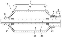
- FIG. 2 shows a cross-sectional view (partially plan view) of a distal portion of the light irradiation medical device according to the embodiment of the present invention.
- FIG. 2 illustrates a cross-sectional view of a distal portion including a balloon of the light irradiation medical device illustrated in FIG. 1.
- FIG. 3 shows a cross-sectional view of a catheter shaft of the light irradiation medical device shown in FIG. 2.
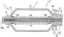
- FIG. 4 illustrates a modification of the cross-sectional view of the light irradiation medical device illustrated in FIG. 2.
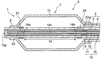
- FIG. 9 illustrates a modification of the cross-sectional view (partially plan view) of the light irradiation medical device illustrated in FIG. 4.
- FIG. 1 shows a cross-sectional view (partially plan view) of a distal portion of the light irradiation medical device according to the embodiment of the present invention.
- FIG. 2 illustrates a cross-sectional view of a distal portion including a
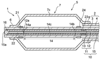
- FIG. 9 shows another modification of the cross-sectional view (partial plan view) of the light irradiation medical device shown in FIG. 4.
- FIG. 13 shows another modification of the cross-sectional view (partially plan view) of the light irradiation medical device shown in FIG. 4.
- FIG. 2 is a schematic diagram illustrating a positional relationship between a first radiopaque marker and a second radiopaque marker in a perspective direction.
- FIG. 2 is a schematic diagram illustrating a positional relationship between a first radiopaque marker and a second radiopaque marker in a perspective direction.
- FIG. 1 shows a cross-sectional view (partial plan view) of a distal portion of the light irradiation medical device according to the embodiment of the present invention
- FIG. 2 shows a distal portion including a balloon of the light irradiation medical device shown in FIG.
- FIG. 3 is a cross-sectional view of a portion
- FIG. 3 is a cross-sectional view of a catheter shaft of the light irradiation medical device shown in FIG.
- the light irradiation medical device is used for irradiating light of a specific wavelength to a treatment portion which is a target tissue such as a cancer cell in a body lumen such as a blood vessel or a digestive tract in PDT or photoablation.
- a treatment portion which is a target tissue such as a cancer cell in a body lumen such as a blood vessel or a digestive tract in PDT or photoablation.
- the light irradiation medical device may be independently delivered to the treatment site, or may be used together with a delivery catheter or endoscope.
- the medical instrument In the treatment using an endoscope, the medical instrument is placed in the body from the distal side of the forceps port of the endoscope through the forceps port of the endoscope, and is delivered to the treatment section.
- the light irradiation medical device 1 includes a catheter shaft 2, a balloon 5, a light guide device 10, a first radiopaque marker 21, and a second radiopaque marker 22.
- the proximal side of the light irradiation medical device 1 refers to the user, that is, the operator's hand side with respect to the extending direction of the catheter shaft 2, and the distal side is the direction opposite to the proximal side, That is, it indicates the treatment target side.
- a direction from the proximal side to the distal side of the catheter shaft 2 or a direction from the distal side to the proximal side is referred to as a near-far direction.
- the inside of the light irradiation medical device 1 refers to a direction toward the center of the long axis of the catheter shaft 2 in the radial direction of the catheter shaft 2, and the outside refers to a radiation direction opposite to the inside.
- the materials of the catheter shaft 2, the balloon 5, the light guide device 10, the first radiopaque marker 21 and the second radiopaque marker 22 constituting the light irradiation medical device 1 have biocompatibility.
- the catheter shaft 2 extends in the near-far direction, and a balloon 5 is disposed at a distal portion of the catheter shaft 2.
- the catheter shaft 2 has a tubular structure for disposing the light guide device 10 in its lumen. Further, since the catheter shaft 2 is to be inserted into the body, it preferably has flexibility.
- a hub may be provided on the proximal side of the catheter shaft 2.
- the balloon 5 is configured such that a pressure fluid is supplied from the hub to the inside of the balloon 5 through the catheter shaft 2, and the pressure fluid is supplied to the inside of the balloon 5 so that the balloon 5 can be expanded. On the other hand, by extracting the pressure fluid from the inside of the balloon 5, the balloon 5 can be contracted. When the balloon 5 is expanded, the outer surface of the balloon 5 comes into contact with the inner wall of a blood vessel, a digestive tract, or the like, so that the catheter shaft 2 can be fixed in the body.
- the catheter shaft 2 may have a first lumen communicating with the inside of the balloon 5 and a second lumen through which the light guide device 10 is inserted. This allows the first lumen to function as a flow path for the pressure fluid that expands and contracts the balloon 5, and the second lumen to function as an insertion path for the light guide device 10.
- the catheter shaft 2 is composed of an inner tube 3 and an outer tube 4, a space between the inner tube 3 and the outer tube 4 is a first lumen 2a, and a lumen of the inner tube 3 is a first lumen 2a. It may be 2 lumens 2b.
- the catheter shaft 2 is made of, for example, a polyolefin resin (for example, polyethylene or polypropylene), a polyamide resin (for example, nylon), a polyester resin (for example, PET), an aromatic polyetherketone resin (for example, PEEK), a polyether polyamide resin, It can be made of a synthetic resin such as a polyurethane resin, a polyimide resin, or a fluororesin (for example, PTFE, PFA, or ETFE), or a metal such as stainless steel, carbon steel, or a nickel titanium alloy. These may be used alone or in combination of two or more.
- a polyolefin resin for example, polyethylene or polypropylene
- a polyamide resin for example, nylon
- a polyester resin for example, PET
- an aromatic polyetherketone resin for example, PEEK
- a polyether polyamide resin It can be made of a synthetic resin such as a polyurethane resin, a polyimide resin, or a fluororesin (
- the balloon 5 includes, in order from the distal side, a distal fixing portion 6 fixed to the catheter shaft 2, an inflating portion 7 not fixed to the catheter shaft 2, and a proximal side fixed to the catheter shaft 2. It may have a fixing portion 8.
- the catheter shaft 2 is composed of an inner tube 3 and an outer tube 4. On the distal side of the catheter shaft 2, the inner tube 3 extends from the distal end of the outer tube 4 and penetrates the balloon 5 in the perspective direction. Is preferred.
- the inflatable portion 7 of the balloon 5 may have a straight tube portion 7a and tapered portions 7b formed on the distal and proximal sides of the straight tube portion 7a, respectively.
- the balloon 5 is preferably made of resin.
- the resin constituting the balloon 5 include a polyamide resin, a polyester resin, a polyurethane resin, a polyolefin resin, a vinyl chloride resin, a silicone resin, and a natural rubber. These may be used alone or in combination of two or more. Among them, polyamide resins, polyester resins, and polyurethane resins are preferably used. As these resins, an elastomer resin can be used from the viewpoint of thinning and flexibility of the balloon 5.
- the catheter shaft 2 and the balloon 5 include a light transmitting material. More preferably, both the portion of the catheter shaft 2 covered by the balloon 5 and the balloon 5 are made of a light-transmitting material. Accordingly, when the non-existing portion 14 of the clad is located inside the balloon 5, the target tissue can be efficiently irradiated with light at a position corresponding to the balloon 5.
- the light-transmitting material include (meth) acrylic resin (for example, polymethyl methacrylate (PMMA)), polycarbonate resin (for example, polydiethylene glycol bisallyl carbonate (PC)), and polystyrene-based resin (for example, methyl methacrylate / styrene). Examples thereof include synthetic resins such as a polymer resin (MS), an acrylonitrile styrene resin (SAN)), a polyamide resin (for example, nylon), and a polyolefin resin.
- MS polymer resin
- SAN acrylonitrile styrene resin
- the catheter shaft 2 and the balloon 5 preferably contain a light-diffusing material, and both the portion of the catheter shaft 2 covered by the balloon 5 and the balloon 5 are made of a light-diffusing material. Is more preferable.
- the target tissue can be irradiated with light evenly.
- the light diffusing material include inorganic particles such as titanium oxide, barium sulfate, and calcium carbonate, and organic particles such as cross-linked acrylic particles and cross-linked styrene particles.
- the light guide device 10 is arranged in the lumen of the catheter shaft 2 and is movable in the near and far directions.
- the light guide device 10 includes an optical fiber 11 extending in the near and far directions, and a tubular member 15 that covers the optical fiber 11 and has optical transparency. In order to irradiate light uniformly, the cylindrical member 15 may further have a light diffusing property.
- the optical fiber 11 has a core 12 and a clad 13 covering the outside of the core 12, and has a non-existent portion 14 of the clad at a part of a distal portion of the core 12.
- the light guide device 10 Since the light guide device 10 is movable in the near and far directions with respect to the catheter shaft 2, the light guide device 10 is used to deliver the catheter shaft 2 to a target tissue before the light guide device 10 is inserted into the lumen of the catheter shaft 2. Guide wire can be inserted.
- the light irradiation medical device 1 may include a guide wire extending in the near-far direction.
- the second lumen 2b can function as a guide wire insertion passage.
- the catheter shaft 2 may have a third lumen through which a guide wire is inserted.
- the optical fiber 11 is a transmission path for transmitting an optical signal to a target tissue.
- a light source such as a semiconductor laser is connected to the proximal side of the optical fiber 11.
- the material constituting the core 12 and the clad 13 is not particularly limited, and glass such as plastic, quartz glass, and fluoride glass can be used.
- the tubular member 15 is a tubular member extending in the near-far direction.
- the tubular member 15 preferably covers the entire optical fiber 11 in the perspective direction.
- the cylindrical member 15 covers the entire optical fiber 11 in the circumferential direction.
- the distal end of the tubular member 15 is disposed more distally than the distal end of the optical fiber 11. Thereby, deformation and damage at the distal end of the optical fiber 11 can be prevented.
- the tubular member 15 may have any light transmitting property, but is preferably made of resin.
- the resin forming the tubular member 15 include polyamide resin, polyester resin, polyurethane resin, polyolefin resin, fluorine resin, vinyl chloride resin, silicone resin, and natural rubber. These may be used alone or in combination of two or more. Among them, polyamide-based resins, polyester-based resins, polyurethane-based resins, polyolefin-based resins, and fluorine-based resins are preferably used.
- the resin constituting the tubular member 15 may be added with a light diffusing material such as inorganic particles such as titanium oxide, barium sulfate, and calcium carbonate, and organic particles such as cross-linked acrylic particles and cross-linked styrene particles. it can.
- a light diffusing material such as inorganic particles such as titanium oxide, barium sulfate, and calcium carbonate, and organic particles such as cross-linked acrylic particles and cross-linked styrene particles. it can.
- the non-cladding portion 14 refers to a portion where the cladding 13 does not exist in at least a part of the core 12 in the circumferential direction, and is a light emitting area of the optical fiber 11.
- a side irradiation type light irradiation medical device can be configured.
- the target tissue can be irradiated with light while keeping a constant distance in the radial direction.
- the cladding 13 does not exist in the entire circumferential direction of the core 12. Accordingly, a side-illuminated light irradiation medical device that emits light from the core 12 to the entire circumferential direction can be configured.
- the position where the non-existing portion 14 of the clad is provided in the near and far directions is not particularly limited as long as it is a part of the distal portion of the core 12, but is preferably provided at a portion including the distal end 12 a of the core 12. This makes it easier to form the non-existing portion 14 of the clad, and also increases the flexibility at the distal end of the light guide device 10.
- the position of the distal end 14a of the non-existent portion 14 of the clad coincides with the position of the distal end 12a of the core 12. This eliminates the need for a difficult process of forming the non-existent portion 14 of the optical fiber 11 while leaving the clad 13 at the portion including the distal end of the optical fiber 11, thereby facilitating the process of forming the light emitting area of the optical fiber 11. it can.
- the distal end 14 a of the non-cladding portion 14 is located closer to the distal side than the distal fixing portion 6 of the balloon 5. It is preferable that the proximal end 14b of the non-existent portion 14 of the clad is disposed more distally than the proximal fixing portion 8 of the balloon 5. In addition, the distal end 14a of the non-existent portion 14 of the clad is disposed more distally than the center of the balloon 5 in the perspective direction, and the proximal end 14b of the non-existent portion 14 of the clad is positioned in the perspective direction. More preferably, it is located closer to the center of 5 than it is. By providing the non-cladding portion 14 at such a position, a position corresponding to the balloon 5 can be set as a light emitting area.
- the inflation portion 7 of the balloon 5 has a straight tube portion 7a and tapered portions 7b formed on the distal side and the proximal side of the straight tube portion 7a, respectively.
- the length in the direction is preferably longer than the length of the straight pipe portion 7a of the balloon 5. Since the light emitting area can be enlarged by forming the non-existent portion 14 of the clad to be long in the near and far directions, it is possible to irradiate a wide range at a time.
- the length of the non-existent portion 14 of the clad in the distance direction may be equal to or less than the length of the straight tube portion 7a of the balloon 5, but may be smaller than the length of the tapered portion 7b of the balloon 5 so that irradiation can be performed over a wide range at a time. Is also preferably long.
- the non-existent portion 14 of the clad can be formed by peeling the clad 13 by, for example, etching or polishing. Further, it is more preferable to roughen the outer surface of the non-existing portion 14 of the clad by a method such as sanding. Thereby, light diffusivity can be improved.
- the non-existing portion 14 of the clad is covered by the tubular member 15, and it is more preferable that the non-existing portion 14 of the cladding be covered by the tubular member 15 over the entire distance. Accordingly, the portion of the core 12 corresponding to the non-existing portion 14 of the clad is protected, so that the core 12 at the position corresponding to the non-existing portion 14 of the clad can be prevented from being damaged, deformed, or broken.
- the optical fiber 11 is covered by the tubular member 15 over the entire distance. Since the entire optical fiber 11 is protected by covering with the tubular member 15, damage, deformation, and breakage of the core 12 can be suppressed.
- the light irradiation medical device 1 is further disposed on the tubular member 15 on the distal side of the distal end 12a of the core 12 with the first radiopaque marker 21 disposed on the distal portion of the catheter shaft 2.
- a second radiopaque marker 22 Since the position of the catheter shaft 2 can be specified under X-ray fluoroscopy by the first radiopaque marker 21, the position of the balloon 5 disposed on the catheter shaft 2 can be adjusted to the position of the tissue to be irradiated. .
- the second radiopaque marker 22 is disposed more distally than the distal end 12a of the core 12, the second radiopaque marker 22 is generated when the second radiopaque marker 22 is attached to the tubular member.
- the first radiopaque marker 21 and the second radiopaque marker 22 may be collectively referred to as a “radiopaque marker”.
- the shape of the radiopaque marker is not particularly limited, but may be, for example, a ring or a rod. Further, the radiopaque marker may have a coil shape, or may have a C-shaped cross section in which a ring has a slit. When the radiopaque marker is annular or coil-shaped, it is easy to attach the marker to the outside of the catheter shaft 2 or the tubular member 15. When the radiopaque marker has a rod shape or a coil shape, it is easy to arrange the marker in the lumen of the catheter shaft 2 or the tubular member 15.
- the first radiopaque marker 21 is preferably annular and attached to the outside of the catheter shaft 2.
- the second radiopaque marker 22 is preferably annular and attached to the outside of the tubular member 15. This makes it possible to easily attach the radiopaque marker.
- the length of the radiopaque marker in the perspective direction is shorter than the length of the tapered portion 7b of the balloon 5 in the perspective direction.
- the first radiopaque marker 21 and the second radiopaque marker 22 are preferably made of a material containing a metal material such as platinum, gold, silver, tungsten, tantalum, iridium, palladium, and alloys thereof.
- the radiopaque marker may be a metal marker made of the above-mentioned metal material, or may be a resin marker made of the above-mentioned metal material.
- the first radiopaque marker 21 is preferably attached outside the catheter shaft 2. Accordingly, the light guide device 10 can be easily inserted into the lumen of the catheter shaft 2 while preventing the inner diameter of the catheter shaft 2 from being reduced.
- the first radiopaque marker 21 is annular and attached to the outside of the catheter shaft 2.
- the outer diameter of the catheter shaft 2 at the portion where the first radiopaque marker 21 is attached is the first radiopaque marker 21. It is preferable that the outer diameter is smaller than the outer diameter of the portion where the transmission marker 21 is not attached. Accordingly, the first radiopaque marker 21 can be attached so as to bite into the outer surface of the catheter shaft 2, so that the outer diameter of the portion of the catheter shaft 2 to which the first radiopaque marker 21 is attached increases. Can be suppressed.
- the balloon 5 includes, in order from the distal side, a distal fixing portion 6 fixed to the catheter shaft 2, an inflating portion 7 not fixed to the catheter shaft 2, and a proximal side fixed to the catheter shaft 2. It is preferable that the first radiopaque marker 21 be disposed closer to the distal side than the distal-side fixed portion 6. By arranging the first radiopaque marker 21 in this manner, an increase in the outer diameter of the catheter shaft 2 at a position corresponding to the distal fixing portion 6 of the balloon 5 can be suppressed.
- the first radiopaque marker 21 is preferably disposed at a position corresponding to the inflatable portion 7 of the balloon 5, and is disposed at a position corresponding to the straight pipe portion 7a or the tapered portion 7b of the inflatable portion 7. More preferably, it is performed. Further, the first radiopaque marker 21 may be arranged at a position corresponding to a portion including a boundary between the straight pipe portion 7a and the tapered portion 7b. Furthermore, the first radiopaque marker 21 may be arranged at a position corresponding to at least one of the distal end and the proximal end of the straight pipe portion 7a. By arranging the first radiopaque marker 21 in this manner, the position of the catheter shaft 2 can be more easily confirmed under fluoroscopy.
- the proximal end of the first radiopaque marker 21 is It is preferable to be disposed more distally than the distal end 14a of the.
- the proximal end of the second radiopaque marker 22 is preferably located more distally than the distal end 14a of the cladding non-existent portion 14, and from the distal end 14a of the cladding non-existent portion 14. It is more preferable that the first radiopaque marker 21 is disposed on the distal side at least by the length in the perspective direction. By arranging the second radiopaque marker 22 away from the light emitting area in this way, it is possible to prevent the second radiopaque marker 22 from generating heat due to light energy. In addition, the first radiopaque marker 21 and the second radiopaque marker 22 can be easily distinguished even under X-ray fluoroscopy.
- the distal end of the second radiopaque marker 22 is ,
- the proximal end of the second radiopaque marker 22 is located closer to the distal end than the distal end of the distal fixing portion 6 of the balloon 5, and is located closer to the distal side than the center of the balloon 5 in the perspective direction.
- the length of the second radiopaque marker 22 in the perspective direction is preferably longer than the length of the first radiopaque marker 21 in the perspective direction. Even if two markers overlap, the second radiopaque marker 22 is not completely hidden by the first radiopaque marker 21, so that the position of the marker can be easily recognized and the position of the optical fiber 11 can be easily specified. .
- the second radiopaque marker 22 is annular and is attached to the outside of the tubular member 15.
- the outer diameter of the tubular member 15 at the portion where the second radiopaque marker 22 is attached is cylindrical. It is preferable that the outer diameter of the portion of the member 15 to which the second radiopaque marker 22 is not attached be smaller. Accordingly, the second radiopaque marker 22 can be attached so as to bite into the outer surface of the tubular member 15, and thus the outer diameter of the portion of the tubular member 15 to which the second radiopaque marker 22 is attached. Increase can be suppressed. In addition, it is possible to treat deep tissue and luminal tissue having a small inner diameter that could not be reached until now.
- the second radiopaque marker 22 may be swaged at a desired position on the tubular member 15.
- the second radiopaque marker 22 is preferably a metal marker.
- the thickness of the second radiopaque marker 22 may be smaller than the thickness of the cylindrical member 15. preferable.
- the inner diameter of the cylindrical member 15 preferably has a certain size in the near and far directions.
- the outer diameter of the cylindrical member 15 is set so that the light guide device 10 can easily move in the distance direction in the lumen of the catheter shaft 2.
- the outer diameter of the tubular member 15 may decrease toward the distal end, and may have a constant size in the near-far direction.
- the first radiopaque marker 21 has an annular shape and is attached to the outside of the catheter shaft 2.
- the length of the second radiopaque marker 22 in the perspective direction is the distance in the perspective direction of the first radiopaque marker 21. It is preferably longer than the length. Since the second radiopaque marker 22 is not completely hidden by the first radiopaque marker 21 even when the two markers overlap, the position of the light emitting area of the optical fiber 11 can be easily specified.
- FIG. 4 shows a modification of the cross-sectional view of the light irradiation medical device 1 shown in FIG.
- the opening at the distal end of the tubular member 15 may be sealed. This makes it difficult for the optical fiber 11 disposed in the lumen of the tubular member 15 to drop off from the distal end face side of the light guide device 10.
- a heat generating device such as a heater or a soldering iron is brought into close proximity to the distal end of the tubular member 15 to close the distal end of the tubular member 15.
- the opening at the distal end of the tubular member 15 is sealed so that the distal end of the lumen of the tubular member 15 is closer to the distal end 15 a of the tubular member 15.
- the proximal end of the second radiopaque marker 22 is located more distally than the distal end of the lumen of the tubular member 15. This can prevent the optical fiber 11 from being deformed or damaged when the second radiopaque marker 22 is attached to the tubular member 15.
- FIGS. 5 to 7 show modified examples of the cross-sectional views (partial plan views) of the light irradiation medical device 1 shown in FIG.
- the second radiopaque marker 22 is preferably disposed in the lumen of the tubular member 15 at a position more distal than the distal end 12 a of the core 12.
- the outer diameter of the second radiopaque marker 22 is smaller than the inner diameter of the tubular member 15.
- the distal end 15a of the tubular member 15 is located more distally than the distal end 12a of the core 12. In that case, it is more preferable that the distal end of the lumen of the tubular member 15 is disposed more distally than the distal end 12a of the core 12. Thereby, the inner cavity of the tubular member 15 (specifically, a portion from the distal end of the inner cavity of the tubular member 15 to the distal end 12a of the core 12 in the inner cavity of the tubular member 15) is formed.
- the radiopaque marker 22 can be arranged.
- the second radiopaque marker 22 may have a coil shape.
- the distal side of the second radiopaque marker 22 has a coil shape, and it is more preferable that the second radiopaque marker 22 has a coil shape over the entire distance direction.
- the second radiopaque marker 22 may be rod-shaped. Thereby, the step of forming the second radiopaque marker 22 can be simplified.
- the second radiopaque marker 22 may be a solid rod or a hollow rod.
- the cross-sectional shape of the second radiopaque marker 22 perpendicular to the perspective direction can be circular, elliptical, polygonal, or a combination thereof, but is circular in order to protect the inner wall of the tubular member 15. Alternatively, the shape is preferably elliptical.
- the outer diameter of the second radiopaque marker 22 is smaller than the outer diameter of the core 12 in the cladding-free portion 14. Is preferred. By setting the outer diameter of the marker in this way, the flexibility at the distal portion of the light guide device 10 can be increased.
- the second radiopaque marker 22 is annular or coil-shaped and the second radiopaque marker 22 is arranged in the lumen of the tubular member 15, the outer diameter of the core 12 in the cladding-free portion 14 is reduced.
- the inner diameter of the second radiopaque marker 22 is larger than the inner diameter of the second radiopaque marker 22. This can prevent the non-existing portion 14 of the clad from being inserted into the second radiopaque marker 22.
- the center 7c of the inflated portion 7 of the balloon 5 and the center 14c of the non-cladding portion 14 in the far and near directions are arranged so as to be aligned, as shown in FIGS.
- the proximal end is disposed more distally than the distal end of the distal fixing portion 6 of the balloon 5, and the proximal end of the second radiopaque marker 22 is located closer to the center of the balloon 5 in the perspective direction. Preferably, it is located distally.
- the length of the light emitting area and the length of the marker can be secured.
- a spacer is disposed between the second radiopaque marker 22 and the non-existent portion 14 of the clad. Is also good.
- the spacer includes a covering member that covers the distal end surface of the non-existent portion 14 of the clad.
- the spacer may include a light-reflective material.
- Light reflective materials include, for example, aluminum, gold, silver, copper, tin, titanium dioxide, tantalum pentoxide, aluminum oxide, silicon dioxide, magnesium fluoride, or combinations thereof.
- a resin tip 16 may be provided at the distal end of the tubular member 15 as shown in FIG. This makes it difficult for the second radiopaque marker 22 arranged in the lumen of the tubular member 15 to fall off the distal end face side of the light guide device 10.
- the resin chip 16 can be formed in, for example, a hemispherical shape, a semi-elliptical spherical shape, a columnar shape, and a polygonal columnar shape. It is preferable that a part of the resin chip 16 is disposed in the inner cavity of the tubular member 15. Further, it is preferable that the resin chip 16 has a plug shape inserted into the lumen of the tubular member 15.
- a material forming the resin chip 16 a material similar to a material forming the tubular member 15 can be adopted.
- the first radiopaque marker 21 The second radiopaque marker 22 and the second radiopaque marker 22 only need to be arranged so as to recognize that they are at corresponding positions, and their relative positions are not particularly limited. For example, as shown in FIG. 1 to FIG. 2 and FIG.
- the second The proximal end of the radiopaque marker 22 may be located more distal than the distal end of the first radiopaque marker 21. Further, although not shown, the distal end of the second radiopaque marker 22 may be disposed closer to the proximal end than the proximal end of the first radiopaque marker 21. Thereby, since the position of the marker can be shifted in the distance direction, it is possible to suppress a local increase in rigidity at the distal end of the light irradiation medical device 1. Under fluoroscopy, the two markers are observed spaced apart.
- the second radiopaque marker 22 Is disposed more distally than the distal end of the first radiopaque marker 21, and the proximal end of the second radiopaque marker 22 is the proximal end of the first radiopaque marker 21. It may be located more proximally than that. Since the marker is observed in a cross shape under X-ray fluoroscopy, the position of the marker can be easily recognized.
- FIGS. 8 and 9 are schematic diagrams illustrating the positional relationship between the first radiopaque marker 21 and the second radiopaque marker 22 in the perspective direction. 8 and 9, the left side of the drawing indicates the distal side, and the right side indicates the proximal side. As shown in FIG. 8, when the position is adjusted so that the center 7 c of the inflatable portion 7 of the balloon 5 and the center 14 c of the non-cladding portion 14 in the near and far directions are aligned, the proximal position of the second radiopaque marker 22 is adjusted. The end is located more proximally than the distal end of the first radiopaque marker 21 and more distally than the proximal end of the first radiopaque marker 21.
- the distal end may be located more distally than the distal end of the first radiopaque marker 21.
- the second radiopaque marker 22 The distal end is located proximal to the distal end of the first radiopaque marker 21 and distal to the proximal end of the first radiopaque marker 21, and the second radiopaque marker The proximal end of 22 may be located closer to the proximal end of the first radiopaque marker 21. Under X-ray fluoroscopy, the marker is observed in a T-shape, making it easier to visually recognize the position of the marker.
- a radiopaque marker may be further provided to make it easier to confirm the positions of the cylindrical member 15 and the catheter shaft 2.
- the light irradiation medical device 1 is a radiopaque marker disposed on a tubular member 15, which is closer to a proximal end 14 b of a cladding-free portion 14. It is preferable to further include a third radiopaque marker 23 located on the proximal side.
- the light irradiation medical device 1 is a radiopaque marker disposed on the catheter shaft 2 and located closer to the fourth radiopaque marker 21 than the first radiopaque marker 21. It is preferable to further include a radiopaque marker 24. This makes it easier to identify the position of the catheter shaft 2 in the perspective direction under X-ray fluoroscopy.
- the shapes of the third radiopaque marker 23 and the fourth radiopaque marker 24 are not particularly limited, but may be annular or coiled.
- the third radiopaque marker 23 is preferably annular, and is preferably mounted outside the tubular member 15.
- the outer diameter of the third radiopaque marker 23 is smaller than the inner diameter of the catheter shaft 2 (the diameter of the second lumen 2b in FIG. 3) so that the light guide device 10 is disposed in the lumen of the catheter shaft 2.
- the cylinder in the portion where the second radiopaque marker 22 is mounted The outer diameter of the tubular member 15 is preferably smaller than the outer diameter of the tubular member 15 at the portion where the third radiopaque marker 23 is attached.
- an increase in the outer diameter can be suppressed, so that flexibility is easily ensured and the shape of the body lumen can be easily followed.
- the portion of the tubular member 15 where the third radiopaque marker 23 is attached it is possible to prevent the optical fiber 11 from being excessively tightened, and to suppress damage, deformation and breakage of the optical fiber 11.
- the fourth radiopaque marker 24 is preferably annular, and is preferably mounted outside the catheter shaft 2.
- the fourth radiopaque marker 24 can be arranged on the catheter shaft 2 similarly to the first radiopaque marker 21.
- the length of the third radiopaque marker 23 in the perspective direction is longer than the length of the fourth radiopaque marker 24 in the perspective direction.
- the third radiopaque marker 23 and The position of the fourth radiopaque marker 24 may be any position as long as it can be recognized as being at the corresponding position, and the relative position is not particularly limited.
- the relative position is not particularly limited. For example, as shown in FIGS. 1 and 2 and FIGS. 4 to 7, when the position is adjusted so that the center 7c of the inflated portion 7 of the balloon 5 and the center 14c of the non-existent portion 14 of the cladding are aligned in the distance direction.
- the proximal end of the fourth radiopaque marker 24 may be located more distally than the distal end of the third radiopaque marker 23. Further, although not shown, the distal end of the fourth radiopaque marker 24 may be disposed closer to the proximal end than the proximal end of the third radiopaque marker 23. This makes it possible to shift the position of the marker in the perspective direction, so that it is possible to suppress a local increase in rigidity. Under fluoroscopy, the two markers are observed spaced apart.
- the distal end of the fourth radiopaque marker 24 is adjusted when the position is adjusted so that the center 7c of the inflated portion 7 of the balloon 5 and the center 14c of the non-cladding portion 14 are aligned in the distance direction.
- the proximal end of the fourth radiopaque marker 24 is formed.
- the distal end may be located more distally than the distal end of the third radiopaque marker 23.
- the proximal end of the fourth radiopaque marker 24 is , Disposed closer to the proximal end of the third radiopaque marker 23, and the distal end of the fourth radiopaque marker 24 is closer to the distal end of the third radiopaque marker 23.
- the third radiopaque marker 23 may be located on the distal side from the proximal side of the third radiopaque marker 23. Under X-ray fluoroscopy, the marker is observed in a T-shape, making it easier to visually recognize the position of the marker.
- the length of the third radiopaque marker 23 in the perspective direction is longer than the length of the fourth radiopaque marker 24 in the perspective direction.
- At least the third radiopaque marker 23 and the fourth radiopaque marker 24 Preferably, either one of the distal ends is located more proximally than the proximal end of the non-cladding portion 14. Thereby, it becomes easy to specify the position of the proximal end of the non-existing portion 14 of the clad, which becomes the light emitting area.
- the lengths and positional relationships of the first to fourth radiopaque markers in the distance direction can be appropriately combined with the above-described embodiments.
Landscapes
- Health & Medical Sciences (AREA)
- Life Sciences & Earth Sciences (AREA)
- Engineering & Computer Science (AREA)
- Biomedical Technology (AREA)
- Surgery (AREA)
- Public Health (AREA)
- Veterinary Medicine (AREA)
- Animal Behavior & Ethology (AREA)
- General Health & Medical Sciences (AREA)
- Nuclear Medicine, Radiotherapy & Molecular Imaging (AREA)
- Heart & Thoracic Surgery (AREA)
- Pathology (AREA)
- Physics & Mathematics (AREA)
- Molecular Biology (AREA)
- Medical Informatics (AREA)
- Radiology & Medical Imaging (AREA)
- Otolaryngology (AREA)
- Electromagnetism (AREA)
- Optics & Photonics (AREA)
- Oral & Maxillofacial Surgery (AREA)
- Biophysics (AREA)
- Child & Adolescent Psychology (AREA)
- Pulmonology (AREA)
- Anesthesiology (AREA)
- Hematology (AREA)
- Media Introduction/Drainage Providing Device (AREA)
- Laser Surgery Devices (AREA)
- Radiation-Therapy Devices (AREA)
Abstract
遠近方向に延在しているカテーテルシャフト2と、カテーテルシャフト2の遠位部に配置されているバルーン5と、カテーテルシャフト2の内腔に配置されており遠近方向に移動可能な導光装置10とを有する光照射医療装置1であって、導光装置10は、光ファイバー11と、光ファイバー11を覆いかつ光透過性を有する筒状部材15とを有し、光ファイバー11は、コア12と、コア12の外方を被覆するクラッド13とを有し、コア12の遠位部の一部にクラッドの非存在部14を有し、更に、カテーテルシャフト2の遠位部に配置されている第1放射線不透過マーカー21と、コア12の遠位端12aよりも遠位側において筒状部材15に配置されている第2放射線不透過マーカー22と、を有している。
Description
本発明は、血管や消化管等の体内管腔において、がん細胞等の組織に光を照射するための光照射医療装置に関する。
光線力学的療法(Photodynamic Therapy:PDT)では、光増感剤を静脈注射や腹腔内投与で体内に投与し、がん細胞等の対象組織に光増感剤を集積させ、特定の波長の光を照射することにより光増感剤を励起させる。励起された光増感剤が基底状態に戻るときにエネルギー転換が生じ、活性酸素種を発生させる。活性酸素種が対象組織を攻撃することにより、対象組織を除去することができる。また、レーザー光を用いたアブレーション(組織焼灼)では、対象組織にレーザー光を照射し、焼灼することが行われる。
PDTや光アブレーションで使用する光照射医療装置では、対象組織に光を照射するためにカテーテル管内に光ファイバーが配置される。例えば、特許文献1には、カテーテル管内の第1の孔内に、カテーテル管の基端部からのレーザーエネルギーを遠隔端部に伝達する光学的ファイバーが配置されていることが開示されている。カテーテル気球(バルーン)がカテーテル管の遠隔端部範囲を取り巻いており、カテーテル管の遠位端部の廻りには放射線不透過の目印が取り付けられている。ガイドワイヤーを用いて体内で位置決めした後、カテーテル管からガイドワイヤーを引き出して光学的ファイバーを挿通させる。
特許文献2には、シャフトの内部にレーザーファイバーを挿入可能なレーザーファイバーの誘導カテーテルが開示されている。シャフトの内部にはレーザーファイバーの遠近方向の位置を決めるためのストッパーが形成されている。シャフトの内部はストッパーによりレーザーファイバーのルーメンとガイドワイヤーのルーメンに区画されている。
特許文献3には、光放射ファイバーがバルーン付カテーテル内に位置決めされており、このファイバーが放射線不透過マーカーを担持していることが開示されている。
しかし、特許文献1に記載のカテーテルでは、光ファイバーにはマーカーが取り付けられていないため、X線透視下で光ファイバー自体の位置を確認することはできない。特許文献2に記載のカテーテルも光ファイバーにマーカーが取り付けられていないため、ストッパーに突き当たるまで光ファイバーの位置を特定することはできない。特許文献3には、光ファイバーへのマーカーの取り付けの具体的態様については記載されていないが、取り付け位置や方法によっては光ファイバーの変形や損傷を招くおそれがある。このようにカテーテルの遠近方向において光ファイバーの発光エリアの位置を特定する方法には改善の余地があった。そこで、本発明は、光ファイバーを保護しつつ発光エリアの位置を特定しやすい光照射医療装置を提供することを目的とする。
前記課題を解決することができた本発明の光照射医療装置の一実施態様は、遠近方向に延在しているカテーテルシャフトと、該カテーテルシャフトの遠位部に配置されているバルーンと、カテーテルシャフトの内腔に配置されており遠近方向に移動可能である導光装置とを有する光照射医療装置であって、導光装置は、遠近方向に延在している光ファイバーと、光ファイバーを覆いかつ光透過性を有する筒状部材とを有し、光ファイバーは、コアと、コアの外方を被覆するクラッドとを有し、かつ、コアの遠位部の一部にクラッドの非存在部を有しており、更に、カテーテルシャフトの遠位部に配置されている第1放射線不透過マーカーと、コアの遠位端よりも遠位側において、筒状部材に配置されている第2放射線不透過マーカーと、を有していることに特徴を有する。
上記のように構成された光照射医療装置は、第1放射線不透過マーカーによってX線透視下でカテーテルシャフトの位置を特定することができるため、カテーテルシャフトに配置されているバルーンの位置を照射対象の組織の位置に合わせることができる。また、カテーテルシャフトにバルーンが設けられているため、バルーンを膨張させて照射対象の組織と接触させることにより、カテーテルシャフトを体内に固定することができる。さらに、第2放射線不透過マーカーがコアの遠位端よりも遠位側に配置されているため、筒状部材への第2放射線不透過マーカーの取り付けの際に発生してしまう応力によるコアの変形や損傷を防ぎつつ、X線透視下で光ファイバーの発光エリアとなるクラッドの非存在部の位置を特定しやすくなる。このため、第1放射線不透過マーカーと第2放射線不透過マーカーの位置関係を確認することにより、発光エリアを照射対象の組織に位置合わせしやすくなり、術者の操作負担を軽減することもできる。
第2放射線不透過マーカーは環状であって筒状部材の外方に取り付けられており、第2放射線不透過マーカーが取り付けられている部分における筒状部材の外径は、筒状部材の第2放射線不透過マーカーが取り付けられていない部分の外径よりも小さいことが好ましい。これにより、第2放射線不透過マーカーを筒状部材の外側表面に食い込むように取り付けることができるため、筒状部材のうち第2放射線不透過マーカーを設けた部分の外径の増加を抑制することができる。また、これまで到達できなかった深部組織や内径の狭い管腔組織の治療が可能になる。
第2放射線不透過マーカーは、コアの遠位端よりも遠位側であって筒状部材の内腔に配置されていることが好ましい。これにより、コアの遠位端よりも遠位側で導光装置を細径化することができる。
第1放射線不透過マーカーは環状であってカテーテルシャフトの外方に取り付けられており、第2放射線不透過マーカーの遠近方向の長さは、第1放射線不透過マーカーの遠近方向の長さよりも長いことが好ましい。2つのマーカーが重なっていても第2放射線不透過マーカーが第1放射線不透過マーカーに完全に隠れることがないため、光ファイバーの発光エリアの位置を特定しやすくなる。
第2放射線不透過マーカーは、コイル形状を有していることが好ましい。このように第2放射線不透過マーカーをコイル形状にすることで、コアの遠位端よりも遠位側で導光装置が変形しやすくなり、体内管腔の形状に追随しやすくなる。
第2放射線不透過マーカーは、棒状であることが好ましい。これにより、第2放射線不透過マーカーの形成工程を簡素化することができる。
筒状部材に配置されている放射線不透過マーカーであってクラッドの非存在部の近位端よりも近位側に存在している第3放射線不透過マーカーを更に有していることが好ましい。これにより、筒状部材の遠近方向において発光エリアとなるクラッドの非存在部の両側に放射線不透過マーカーが配置されるため、X線透視下で発光エリアの位置をより特定しやすくなる。
カテーテルシャフトに配置されている放射線不透過マーカーであって第1放射線不透過マーカーよりも近位側に存在している第4放射線不透過マーカーを更に有していることが好ましい。これにより、X線透視下で遠近方向におけるカテーテルシャフトの位置をより一層特定しやすくなる。
バルーンは、遠位側から順に、カテーテルシャフトに固定されている遠位側固定部と、カテーテルシャフトに固定されていない膨張部と、カテーテルシャフトに固定されている近位側固定部とを有しており、第1放射線不透過マーカーは、遠位側固定部よりも近位側に配置されていることが好ましい。これにより、バルーンの遠位側固定部に対応する位置でのカテーテルシャフトの外径の増加を抑制することができる。
バルーンの膨張部は、直管部と、該直管部の遠位側および近位側に各々形成されているテーパー部とを有しており、クラッドの非存在部の遠近方向の長さは、バルーンの直管部の長さよりも長いことが好ましい。このようにクラッドの非存在部を遠近方向に長く形成することで発光エリアを大きくすることができるため、一度に広範囲を照射することができる。
カテーテルシャフトは、バルーン内に連通している第1ルーメンと、導光装置が挿通される第2ルーメンとを有していることが好ましい。これにより、第1ルーメンをバルーンを拡張および収縮させる圧力流体の流路として、第2ルーメンを導光装置の挿通路として機能させることができる。
クラッドの非存在部の遠位端の位置は、コアの遠位端の位置と一致していることが好ましい。これにより、光ファイバーの遠位端を含む部分のクラッドを残しながらクラッドの非存在部を形成するという難しい工程が不要になるため、光ファイバーの発光エリアの形成工程を容易にすることができる。
第1放射線不透過マーカーによってX線透視下でカテーテルシャフトの位置を特定することができるため、カテーテルシャフトに配置されているバルーンの位置を照射対象の組織の位置に合わせることができる。また、カテーテルシャフトにバルーンが設けられているため、バルーンを膨張させて照射対象の組織と接触させることにより、カテーテルシャフトを体内に固定することができる。さらに、第2放射線不透過マーカーがコアの遠位端よりも遠位側に配置されているため、筒状部材への第2放射線不透過マーカーの取り付けの際に発生してしまう応力によるコアの変形や損傷を防ぎつつ、X線透視下で光ファイバーの発光エリアとなるクラッドの非存在部の位置を特定しやすくなる。このため、第1放射線不透過マーカーと第2放射線不透過マーカーの位置関係を確認することにより、発光エリアを照射対象の組織に位置合わせしやすくなり、術者の操作負担を軽減することもできる。
以下、下記実施の形態に基づき本発明をより具体的に説明するが、本発明はもとより下記実施の形態によって制限を受けるものではなく、前・後記の趣旨に適合し得る範囲で適当に変更を加えて実施することも勿論可能であり、それらはいずれも本発明の技術的範囲に包含される。なお、各図面において、便宜上、ハッチングや部材符号等を省略する場合もあるが、かかる場合、明細書や他の図面を参照するものとする。また、図面における種々部材の寸法は、本発明の特徴の理解に資することを優先しているため、実際の寸法とは異なる場合がある。
図1~図3を参照して、光照射医療装置の基本構成について説明する。図1は、本発明の実施の形態に係る光照射医療装置の遠位部分の断面図(一部平面図)を表し、図2は図1に示した光照射医療装置のバルーンを含む遠位部分の断面図を表し、図3は、図2に示した光照射医療装置のカテーテルシャフトの断面図を表す。
本発明に係る光照射医療装置は、PDTや光アブレーションにおいて血管や消化管等の体内管腔でがん細胞等の対象組織である処置部に対して特定の波長の光を照射するために用いられる。光照射医療装置は、単独で処置部まで送達されるものであってもよく、送達用のカテーテルや内視鏡と共に用いられてもよい。内視鏡を用いた治療では、内視鏡の鉗子口を通じて、内視鏡の鉗子口の遠位側から体内に配置され、処置部まで送達される。光照射医療装置1は、カテーテルシャフト2と、バルーン5と、導光装置10と、第1放射線不透過マーカー21と、第2放射線不透過マーカー22とを有している。
本発明において、光照射医療装置1の近位側とは、カテーテルシャフト2の延在方向に対して使用者、つまり術者の手元側を指し、遠位側とは近位側の反対方向、すなわち処置対象側を指す。また、カテーテルシャフト2の近位側から遠位側への方向または、遠位側から近位側への方向を遠近方向と称する。光照射医療装置1の内方とは、カテーテルシャフト2の径方向においてカテーテルシャフト2の長軸中心に向かう方向を指し、外方とは、内方とは反対方向の放射方向を指す。
光照射医療装置1を構成するカテーテルシャフト2、バルーン5、導光装置10、第1放射線不透過マーカー21および第2放射線不透過マーカー22の材料は生体適合性を有することが望ましい。
カテーテルシャフト2は、遠近方向に延在しており、カテーテルシャフト2の遠位部にはバルーン5が配置されている。カテーテルシャフト2は、その内腔に導光装置10を配置するために管状構造を有している。また、カテーテルシャフト2は体内に挿入されるものであるため、好ましくは可撓性を有している。図示していないが、カテーテルシャフト2の近位側にはハブが設けられてもよい。バルーン5は、ハブからカテーテルシャフト2を通じてバルーン5の内部に圧力流体が供給されるように構成され、バルーン5の内部に圧力流体が供給されることにより、バルーン5が拡張可能となっている。一方、バルーン5の内部から圧力流体を引き抜くことにより、バルーン5を収縮することができる。バルーン5を拡張させるとバルーン5の外側表面が血管や消化管等の内壁と接触するため、カテーテルシャフト2を体内に固定することができる。
カテーテルシャフト2は、バルーン5内に連通している第1ルーメンと、導光装置10が挿通される第2ルーメンとを有していてもよい。これにより、第1ルーメンをバルーン5を拡張および収縮させる圧力流体の流路として、第2ルーメンを導光装置10の挿通路として機能させることができる。例えば、図3に示すようにカテーテルシャフト2は内管3と外管4から構成され、内管3と外管4の間の空間が第1ルーメン2aであり、内管3の内腔が第2ルーメン2bであってもよい。
カテーテルシャフト2は、例えば、ポリオレフィン樹脂(例えば、ポリエチレンやポリプロピレン)、ポリアミド樹脂(例えば、ナイロン)、ポリエステル樹脂(例えば、PET)、芳香族ポリエーテルケトン樹脂(例えば、PEEK)、ポリエーテルポリアミド樹脂、ポリウレタン樹脂、ポリイミド樹脂、フッ素樹脂(例えば、PTFE、PFA、ETFE)等の合成樹脂や、ステンレス鋼、炭素鋼、ニッケルチタン合金等の金属から構成することができる。これらは一種のみを単独で用いてもよく、二種以上を組み合わせて用いてもよい。
バルーン5は、遠位側から順に、カテーテルシャフト2に固定されている遠位側固定部6と、カテーテルシャフト2に固定されていない膨張部7と、カテーテルシャフト2に固定されている近位側固定部8とを有していてもよい。その場合、カテーテルシャフト2は内管3と外管4から構成され、カテーテルシャフト2の遠位側では、内管3が外管4の遠位端から延出してバルーン5を遠近方向に貫通していることが好ましい。このようにカテーテルシャフト2とバルーン5を構成することにより、カテーテルシャフト2にバルーン5を接合することができる。
バルーン5の膨張部7は、直管部7aと、直管部7aの遠位側および近位側に各々形成されているテーパー部7bとを有していてもよい。バルーン5の直管部7aの外側表面を血管や消化管等の内壁に接触させることで、カテーテルシャフト2を体内に固定することができる。
バルーン5は樹脂から構成されていることが好ましい。バルーン5を構成する樹脂としては、ポリアミド系樹脂、ポリエステル系樹脂、ポリウレタン系樹脂、ポリオレフィン系樹脂、塩化ビニル系樹脂、シリコーン系樹脂、天然ゴム等が挙げられる。これらは1種のみを用いてもよく、2種以上を併用してもよい。なかでも、ポリアミド系樹脂、ポリエステル系樹脂、ポリウレタン系樹脂が好適に用いられる。これらの樹脂は、バルーン5の薄膜化や柔軟性の点からエラストマー樹脂を用いることができる。
カテーテルシャフト2とバルーン5は、光透過性の材料を含んでいることが好ましい。カテーテルシャフト2のうちバルーン5に覆われている部分とバルーン5の両方が光透過性の材料から構成されていることがより好ましい。これにより、バルーン5の内部にクラッドの非存在部14が位置したときに、バルーン5に対応する位置で対象組織に対して効率よく光を照射することができる。光透過性の材料としては、(メタ)アクリル樹脂(例えば、ポリメチルメタクリレート(PMMA))、ポリカーボネート樹脂(例えば、ポリジエチレングリコールビスアリルカーボネート(PC))、ポリスチレン系樹脂(例えば、メチルメタクリレート・スチレン共重合樹脂(MS)、アクリロニトリルスチレン樹脂(SAN))、ポリアミド樹脂(例えば、ナイロン)、ポリオレフィン樹脂等の合成樹脂を挙げることができる。
カテーテルシャフト2とバルーン5は、光拡散性の材料を含んでいることが好ましく、カテーテルシャフト2のうちバルーン5に覆われている部分とバルーン5の両方が光拡散性の材料から構成されていることがより好ましい。これらの部材に光拡散性を付与することにより、対象組織に対して光をムラなく照射することができる。光拡散性の材料としては、酸化チタン、硫酸バリウム、炭酸カルシウム等の無機系粒子、架橋アクリル系粒子、架橋スチレン系粒子等の有機系粒子が挙げられる。
導光装置10は、カテーテルシャフト2の内腔に配置されており遠近方向に移動可能なものである。導光装置10は、遠近方向に延在している光ファイバー11と、光ファイバー11を覆いかつ光透過性を有する筒状部材15とを有している。光をムラなく照射するためには、筒状部材15は光拡散性をさらに有していてもよい。光ファイバー11は、コア12と、コア12の外方を被覆するクラッド13とを有し、かつ、コア12の遠位部の一部にクラッドの非存在部14を有している。
導光装置10はカテーテルシャフト2に対して遠近方向に移動可能であるため、カテーテルシャフト2の内腔には導光装置10を挿通する前に、カテーテルシャフト2を対象組織まで送達するために用いられるガイドワイヤーを挿通することができる。
図示していないが、光照射医療装置1は、遠近方向に延在しているガイドワイヤーを含んでいてもよい。その場合、第2ルーメン2bをガイドワイヤーの挿通路として機能させることができる。あるいは、カテーテルシャフト2は、ガイドワイヤーが挿通される第3ルーメンを有していてもよい。
光ファイバー11は対象組織まで光信号を送信する伝送路である。光ファイバー11の近位側には半導体レーザー等の光源が接続される。コア12およびクラッド13を構成する材料は特に限定されず、プラスチック、石英ガラス、ふっ化物ガラス等のガラスを用いることができる。
筒状部材15は、遠近方向に延在している筒状の部材である。光ファイバー11を保護するために、筒状部材15は光ファイバー11の遠近方向全体を覆っていることが好ましい。同様の理由から、筒状部材15は光ファイバー11の周方向全体を覆っていることが好ましい。さらに筒状部材15の遠位端は、光ファイバー11の遠位端よりも遠位側に配置されていることが好ましい。これにより、光ファイバー11の遠位端部での変形や損傷を防ぐことができる。
筒状部材15は光透過性を有していればよいが、樹脂から構成されていることが好ましい。筒状部材15を構成する樹脂としては、ポリアミド系樹脂、ポリエステル系樹脂、ポリウレタン系樹脂、ポリオレフィン系樹脂、フッ素系樹脂、塩化ビニル系樹脂、シリコーン系樹脂、天然ゴム等が挙げられる。これらは1種のみを用いてもよく、2種以上を併用してもよい。中でも、ポリアミド系樹脂、ポリエステル系樹脂、ポリウレタン系樹脂、ポリオレフィン系樹脂、フッ素系樹脂が好適に用いられる。
筒状部材15を構成する樹脂には、酸化チタン、硫酸バリウム、炭酸カルシウム等の無機系粒子、架橋アクリル系粒子、架橋スチレン系粒子等の有機系粒子の光拡散性の材料を添加することができる。
クラッドの非存在部14は、コア12の周方向の少なくとも一部でクラッド13が存在していない部分を指し、光ファイバー11の発光エリアとなる。このようなクラッドの非存在部14を設けることによって、側面照射型の光照射医療装置を構成することができる。また、バルーン5を拡張させた状態で発光させることによって、半径方向に一定距離を保ちながら対象組織に光を照射することができる。
クラッドの非存在部14では、コア12の周方向全体でクラッド13が存在していないことが好ましい。これにより、コア12から周方向全体に光を照射する側面照射型の光照射医療装置を構成することができる。
遠近方向においてクラッドの非存在部14が設けられる位置はコア12の遠位部の一部であれば特に制限されないが、コア12の遠位端12aを含む部分に設けられていることが好ましい。これによりクラッドの非存在部14を形成しやすくなり、導光装置10の遠位端部での柔軟性も高めることができる。
図2に示すように、クラッドの非存在部14の遠位端14aの位置は、コア12の遠位端12aの位置と一致していることが好ましい。これにより、光ファイバー11の遠位端を含む部分のクラッド13を残しながらクラッドの非存在部14を形成するという難しい工程が不要になるため、光ファイバー11の発光エリアの形成工程を容易にすることができる。
導光装置10をカテーテルシャフト2の内腔に挿通し、光照射を行う際には、クラッドの非存在部14の遠位端14aは、バルーン5の遠位側固定部6よりも近位側に配置されており、クラッドの非存在部14の近位端14bは、バルーン5の近位側固定部8よりも遠位側に配置されていることが好ましい。また、クラッドの非存在部14の遠位端14aが、遠近方向におけるバルーン5の中央よりも遠位側に配置されており、クラッドの非存在部14の近位端14bが、遠近方向におけるバルーン5の中央よりも近位側に配置されていることがより好ましい。このような位置にクラッドの非存在部14を設けることにより、バルーン5に相当する位置を発光エリアにすることができる。
バルーン5の膨張部7は、直管部7aと、直管部7aの遠位側および近位側に各々形成されているテーパー部7bとを有しており、クラッドの非存在部14の遠近方向の長さは、バルーン5の直管部7aの長さよりも長いことが好ましい。このようにクラッドの非存在部14を遠近方向に長く形成することで発光エリアを大きくすることができるため、一度に広範囲を照射することができる。
クラッドの非存在部14の遠近方向の長さは、バルーン5の直管部7aの長さ以下であってもよいが、一度に広範囲に照射できるように、バルーン5のテーパー部7bの長さよりも長いことが好ましい。
クラッドの非存在部14は、例えばエッチングや研磨によってクラッド13を剥離することで形成することができる。さらに、やすり掛けなどの方法によりクラッドの非存在部14の外側表面を荒らすことがより好ましい。これにより、光拡散性を向上させることができる。
クラッドの非存在部14は、筒状部材15に覆われていることが好ましく、クラッドの非存在部14は遠近方向の全体にわたって筒状部材15に覆われていることがより好ましい。これにより、コア12のうちクラッドの非存在部14に相当する部分が保護されるため、クラッドの非存在部14に相当する位置にあるコア12の損傷、変形、折れを抑制することができる。
光ファイバー11は遠近方向の全体にわたって筒状部材15に覆われていることが好ましい。筒状部材15で覆うことによって、光ファイバー11全体が保護されるため、コア12の損傷、変形、折れを抑制することができる。
光照射医療装置1は、更にカテーテルシャフト2の遠位部に配置されている第1放射線不透過マーカー21と、コア12の遠位端12aよりも遠位側において、筒状部材15に配置されている第2放射線不透過マーカー22と、を有している。第1放射線不透過マーカー21によってX線透視下でカテーテルシャフト2の位置を特定することができるため、カテーテルシャフト2に配置されているバルーン5の位置を照射対象の組織の位置に合わせることができる。また、第2放射線不透過マーカー22がコア12の遠位端12aよりも遠位側に配置されているため、筒状部材への第2放射線不透過マーカー22の取り付けの際に発生してしまう応力によるコア12の変形や損傷を防ぎつつ、X線透視下で光ファイバー11の発光エリアとなるクラッドの非存在部14の位置を特定しやすくなる。このため、第1放射線不透過マーカー21と第2放射線不透過マーカー22の位置関係を確認することにより、発光エリアを照射対象の組織に位置合わせしやすくなり、術者の操作負担を軽減することもできる。以下では、第1放射線不透過マーカー21と第2放射線不透過マーカー22をまとめて「放射線不透過マーカー」と称することがある。
放射線不透過マーカーの形状は特に制限されないが、例えば、環状や棒状であってもよい。また、放射線不透過マーカーは、コイル形状を有していてもよく、リングにスリットが入った断面C字の形状であってもよい。放射線不透過マーカーが環状またはコイル状の場合、カテーテルシャフト2または筒状部材15の外方にマーカーを取り付けやすくなる。放射線不透過マーカーが棒状やコイル形状である場合、カテーテルシャフト2または筒状部材15の内腔にマーカーを配置しやすくなる。
第1放射線不透過マーカー21は環状であってカテーテルシャフト2の外方に取り付けられていることが好ましい。同様に、第2放射線不透過マーカー22は環状であって筒状部材15の外方に取り付けられていることが好ましい。これにより、放射線不透過マーカーの取り付けを簡便に行うことができる。
放射線不透過マーカーの遠近方向の長さは、バルーン5のテーパー部7bの遠近方向の長さよりも短いことが好ましい。このように放射線不透過マーカーの長さを設定することにより、発光エリアの長さを確保しつつ、X線透視下でマーカーを視認しやすくなる。
第1放射線不透過マーカー21および第2放射線不透過マーカー22は、例えば、白金、金、銀、タングステン、タンタル、イリジウム、パラジウムおよびそれらの合金等の金属材料を含む材料から好ましく構成される。放射線不透過マーカーは、上記金属材料から構成されている金属製のマーカーであってもよく、上記金属材料を含んで構成されている樹脂マーカーであってもよい。
第1放射線不透過マーカー21は、カテーテルシャフト2の外方に取り付けられていることが好ましい。これにより、カテーテルシャフト2の内径が狭まることを防ぎつつ、カテーテルシャフト2の内腔に導光装置10を挿通させやすくなる。
第1放射線不透過マーカー21は環状であってカテーテルシャフト2の外方に取り付けられており、第1放射線不透過マーカー21が取り付けられている部分におけるカテーテルシャフト2の外径は、第1放射線不透過マーカー21が取り付けられていない部分の外径よりも小さいことが好ましい。これにより、第1放射線不透過マーカー21をカテーテルシャフト2の外側表面に食い込むように取り付けることができるため、カテーテルシャフト2のうち第1放射線不透過マーカー21が取り付けられている部分の外径の増加を抑制することができる。
バルーン5は、遠位側から順に、カテーテルシャフト2に固定されている遠位側固定部6と、カテーテルシャフト2に固定されていない膨張部7と、カテーテルシャフト2に固定されている近位側固定部8とを有しており、第1放射線不透過マーカー21は、遠位側固定部6よりも近位側に配置されていることが好ましい。このように第1放射線不透過マーカー21を配置することにより、バルーン5の遠位側固定部6に対応する位置でのカテーテルシャフト2の外径の増加を抑制することができる。
遠近方向において、第1放射線不透過マーカー21は、バルーン5の膨張部7に対応する位置に配置されていることが好ましく、膨張部7の直管部7aまたはテーパー部7bに対応する位置に配置されていることがより好ましい。また、第1放射線不透過マーカー21は、直管部7aとテーパー部7bの境界を含む部分に対応する位置に配置されていてもよい。またさらに、第1放射線不透過マーカー21は、直管部7aの遠位端部と近位端部の少なくともいずれか一方に対応する位置に配置されていてもよい。このように第1放射線不透過マーカー21を配置することにより、X線透視下でカテーテルシャフト2の位置をより一層確認しやすくなる。
遠近方向におけるバルーン5の膨張部7の中央7cとクラッドの非存在部14の中央14cを揃えるように配置した場合において、第1放射線不透過マーカー21の近位端は、クラッドの非存在部14の遠位端14aよりも遠位側に配置されていることが好ましい。このように第1放射線不透過マーカー21を発光エリア(クラッドの非存在部14)から離して配置することにより、光照射時に光エネルギーによる第1放射線不透過マーカー21の発熱を防ぐことができる。
第2放射線不透過マーカー22の近位端は、クラッドの非存在部14の遠位端14aよりも遠位側に配置されていることが好ましく、クラッドの非存在部14の遠位端14aから少なくとも第1放射線不透過マーカー21の遠近方向における長さ分だけ遠位側に離れて配置されていることがより好ましい。このように第2放射線不透過マーカー22を発光エリアから離して配置することにより、光エネルギーによる第2放射線不透過マーカー22の発熱を防ぐことができる。また、X線透視下であっても第1放射線不透過マーカー21と第2放射線不透過マーカー22の区別がしやすくなる。
遠近方向におけるバルーン5の膨張部7の中央7cとクラッドの非存在部14の中央14cを揃えるように配置した場合において、図2に示すように、第2放射線不透過マーカー22の遠位端は、バルーン5の遠位側固定部6の遠位端よりも近位側に配置されており、第2放射線不透過マーカー22の近位端は、遠近方向におけるバルーン5の中央よりも遠位側に配置されていることが好ましい。これにより、発光エリアの長さを確保しつつ、マーカーを視認しやすくなる。
第2放射線不透過マーカー22の遠近方向の長さは、第1放射線不透過マーカー21の遠近方向の長さよりも長いことが好ましい。2つのマーカーが重なっていても第2放射線不透過マーカー22が第1放射線不透過マーカー21に完全に隠れることがないため、マーカーの位置を視認しやすくなり、光ファイバー11の位置を特定しやすくなる。
第2放射線不透過マーカー22は環状であって筒状部材15の外方に取り付けられており、第2放射線不透過マーカー22が取り付けられている部分における筒状部材15の外径は、筒状部材15の第2放射線不透過マーカー22が取り付けられていない部分の外径よりも小さいことが好ましい。これにより、第2放射線不透過マーカー22を筒状部材15の外側表面に食い込むように取り付けることができるため、筒状部材15のうち第2放射線不透過マーカー22が取り付けられている部分の外径の増加を抑制することができる。また、これまで到達できなかった深部組織や内径の狭い管腔組織の治療が可能になる。このようにマーカーを取り付ける方法としては、第2放射線不透過マーカー22を筒状部材15の所望の位置でかしめることが挙げられる。放射線不透過マーカーをカテーテルシャフト2や筒状部材15の外方にかしめて取り付けるためには、第2放射線不透過マーカー22は金属マーカーであることが好ましい。
第2放射線不透過マーカー22が環状であって筒状部材15の外方に取り付けられている場合、第2放射線不透過マーカー22の肉厚は、筒状部材15の肉厚よりも薄いことが好ましい。このように第2放射線不透過マーカー22と筒状部材15の肉厚を設定することにより、筒状部材15のうち第2放射線不透過マーカー22を設けた部分の柔軟性を確保することができる。
筒状部材15の内腔に光ファイバー11を挿入しやすいように、筒状部材15の内径は遠近方向において一定の大きさを有していることが好ましい。
筒状部材15の外径は、カテーテルシャフト2の内腔で導光装置10が遠近方向に移動しやすいように設定されていることが好ましい。例えば、筒状部材15の外径は、遠位端に向かって外径が小さくなっていてもよく、遠近方向において一定の大きさを有していてもよい。
第1放射線不透過マーカー21は環状であってカテーテルシャフト2の外方に取り付けられており、第2放射線不透過マーカー22の遠近方向の長さは、第1放射線不透過マーカー21の遠近方向の長さよりも長いことが好ましい。2つのマーカーが重なっていても第2放射線不透過マーカー22が第1放射線不透過マーカー21に完全に隠れることがないため、光ファイバー11の発光エリアの位置を特定しやすくなる。
図4は、図2に示した光照射医療装置1の断面図の変形例を表している。図4に示すように筒状部材15の遠位端部の開口が封止されていてもよい。これにより、筒状部材15の内腔に配置された光ファイバー11が、導光装置10の遠位端面側から脱落しにくくなる。筒状部材15の遠位端部の開口を封止する方法としては、ヒーターや半田ごて等の熱発生装置を筒状部材15の遠位端部に近接させて筒状部材15の遠位端部を溶着する、接着用の樹脂を筒状部材15の遠位端部から封入する方法が挙げられる。
図4に示すように、筒状部材15の遠位端部の開口が封止されることによって筒状部材15の内腔の遠位端が筒状部材15の遠位端15aよりも近位側に配置されている場合、第2放射線不透過マーカー22の近位端が筒状部材15の内腔の遠位端よりも遠位側に配置されていることが好ましい。これにより、筒状部材15への第2放射線不透過マーカー22の取り付けの際に光ファイバー11の変形や損傷を防ぐことができる。
図1~図4を用いて、第2放射線不透過マーカー22が筒状部材15の外方に取り付けられている例を説明した。次に、図5~図7を用いて第2放射線不透過マーカー22が筒状部材15の内腔に配置されている例について説明する。図5~図7は、図4に示した光照射医療装置1の断面図(一部平面図)の変形例を表す。図5~図7に示すように、第2放射線不透過マーカー22は、コア12の遠位端12aよりも遠位側であって筒状部材15の内腔に配置されていることが好ましい。その場合、第2放射線不透過マーカー22の外径は、筒状部材15の内径よりも小さいものとなる。これにより、筒状部材15内に第2放射線不透過マーカー22を設けたとしても、コア12の遠位端12aよりも遠位側で導光装置10を細径化することができる。
筒状部材15の遠位端15aは、コア12の遠位端12aよりも遠位側に位置していることが好ましい。その場合、筒状部材15の内腔の遠位端が、コア12の遠位端12aよりも遠位側に配置されていることがより好ましい。これにより、筒状部材15の内腔(詳細には、筒状部材15の内腔のうち、筒状部材15の内腔の遠位端からコア12の遠位端12aまでの部分)に第2放射線不透過マーカー22を配置することができるようになる。
図5に示すように、第2放射線不透過マーカー22は、コイル形状を有していてもよい。中でも、第2放射線不透過マーカー22の少なくとも遠位側がコイル形状であることが好ましく、第2放射線不透過マーカー22は遠近方向全体にわたってコイル形状であることがより好ましい。このように第2放射線不透過マーカー22をコイル形状にすることで、コア12の遠位端12aよりも遠位側で導光装置10が変形しやすくなり、体内管腔の形状に追随しやすくなる。
図6に示すように、第2放射線不透過マーカー22は、棒状であってもよい。これにより、第2放射線不透過マーカー22の形成工程を簡素化することができる。第2放射線不透過マーカー22は中実の棒状であっても中空の棒状であってもよい。また、第2放射線不透過マーカー22の遠近方向と垂直な断面形状は、円形、楕円形、多角形、またはこれらの組み合わせにすることができるが、筒状部材15の内壁を保護するために円形または楕円形であることが好ましい。
第2放射線不透過マーカー22が筒状部材15の内腔に配置されている場合、第2放射線不透過マーカー22の外径は、クラッドの非存在部14におけるコア12の外径よりも小さいことが好ましい。このようにマーカーの外径を設定することで、導光装置10の遠位部での柔軟性を高めることができる。
第2放射線不透過マーカー22が環状またはコイル状であり、第2放射線不透過マーカー22が筒状部材15の内腔に配置されている場合、クラッドの非存在部14におけるコア12の外径が、第2放射線不透過マーカー22の内径よりも大きいことが好ましい。これにより、第2放射線不透過マーカー22内にクラッドの非存在部14が挿入してしまうことを防ぐことができる。
遠近方向におけるバルーン5の膨張部7の中央7cとクラッドの非存在部14の中央14cを揃えるように配置した場合において、図5~図7に示すように、第2放射線不透過マーカー22の遠位端は、バルーン5の遠位側固定部6の遠位端よりも遠位側に配置されており、第2放射線不透過マーカー22の近位端は、遠近方向におけるバルーン5の中央よりも遠位側に配置されていることが好ましい。これにより、発光エリアとマーカーの長さを確保することができる。
第2放射線不透過マーカー22が筒状部材15の内腔に配置されている場合、図示していないが第2放射線不透過マーカー22とクラッドの非存在部14の間にスペーサーが配置されていてもよい。スペーサーを設けることにより、クラッドの非存在部14が第2放射線不透過マーカー22に直接接触しないため、コア12の損傷を防ぐことができる。スペーサーとしては、クラッドの非存在部14の遠位端面を覆う被覆部材が挙げられる。また、スペーサーは光反射性の材料を含んでいてもよい。これにより、コア12の遠位端12aから照射される光を反射させることで、クラッドの非存在部14から照射される光の光量を増加させることができる。光反射性の材料としては、例えば、アルミニウム、金、銀、銅、スズ、二酸化チタン、五酸化タンタル、酸化アルミニウム、二酸化ケイ素、フッ化マグネシウムまたはこれらの組み合わせが挙げられる。
図7に示すように筒状部材15の遠位端部に樹脂チップ16が設けられていてもよい。これにより筒状部材15の内腔に配置された第2放射線不透過マーカー22が、導光装置10の遠位端面側から脱落しにくくなる。樹脂チップ16は、例えば、半球状、半楕円球状、円柱状、多角柱状に形成することができる。樹脂チップ16の一部が、筒状部材15の内腔に配置されていることが好ましい。また、樹脂チップ16は筒状部材15の内腔に差し込まれている栓形状であることが好ましい。樹脂チップ16を構成する材料としては、筒状部材15を構成する材料と同様のものを採用することができる。
遠近方向においてバルーン5の膨張部7の中央7cとクラッドの非存在部14の中央14cが揃うようにカテーテルシャフト2と導光装置10の相対位置を調整したときに、第1放射線不透過マーカー21と第2放射線不透過マーカー22は、対応する位置にあることを認識できる配置であればよく、その相対位置は特に限定されない。例えば、図1~図2、図4に示すように、遠近方向においてバルーン5の膨張部7の中央7cとクラッドの非存在部14の中央14cが揃うように位置を調整したときに、第2放射線不透過マーカー22の近位端が、第1放射線不透過マーカー21の遠位端よりも遠位側に配置されていてもよい。また、図示していないが、第2放射線不透過マーカー22の遠位端が、第1放射線不透過マーカー21の近位端よりも近位側に配置されていてもよい。これにより、遠近方向においてマーカーの位置をずらすことができるため、光照射医療装置1の遠位端部で局所的に剛性が高まることを抑制できる。X線透視下では2つのマーカーが離間して観察される。
図5~図7に示すように、遠近方向においてバルーン5の膨張部7の中央7cとクラッドの非存在部14の中央14cが揃うように位置を調整したときに、第2放射線不透過マーカー22の遠位端が第1放射線不透過マーカー21の遠位端よりも遠位側に配置されており、第2放射線不透過マーカー22の近位端が第1放射線不透過マーカー21の近位端よりも近位側に配置されていてもよい。X線透視下では十字状にマーカーが観察されるため、マーカーの位置を視認しやすくなる。
図8~図9は、第1放射線不透過マーカー21と第2放射線不透過マーカー22の遠近方向の位置関係を説明する模式図を表している。図8および図9では、図面の左側が遠位側、右側が近位側を示している。図8に示すように、遠近方向においてバルーン5の膨張部7の中央7cとクラッドの非存在部14の中央14cが揃うように位置を調整したときに、第2放射線不透過マーカー22の近位端が、第1放射線不透過マーカー21の遠位端よりも近位側かつ第1放射線不透過マーカー21の近位端よりも遠位側に配置されており、第2放射線不透過マーカー22の遠位端が、第1放射線不透過マーカー21の遠位端よりも遠位側に配置されていてもよい。また、図9に示すように、遠近方向においてバルーン5の膨張部7の中央7cとクラッドの非存在部14の中央14cが揃うように位置を調整したときに、第2放射線不透過マーカー22の遠位端が、第1放射線不透過マーカー21の遠位端よりも近位側かつ第1放射線不透過マーカー21の近位端よりも遠位側に配置されており、第2放射線不透過マーカー22の近位端が、第1放射線不透過マーカー21の近位端よりも近位側に配置されていてもよい。X線透視下ではT字状にマーカーが観察されるため、マーカーの位置を視認しやすくなる。
筒状部材15やカテーテルシャフト2の位置を確認しやすくするために、さらに放射線不透過マーカーが設けられていてもよい。図1~図2、図4~図7に示すように光照射医療装置1は、筒状部材15に配置されている放射線不透過マーカーであってクラッドの非存在部14の近位端14bよりも近位側に存在している第3放射線不透過マーカー23を更に有していることが好ましい。これにより、筒状部材15の遠近方向において発光エリアとなるクラッドの非存在部14の両側に放射線不透過マーカーが配置されるため、X線透視下で発光エリアの位置をより特定しやすくなる。
図1~図7に示すように光照射医療装置1は、カテーテルシャフト2に配置されている放射線不透過マーカーであって第1放射線不透過マーカー21よりも近位側に存在している第4放射線不透過マーカー24を更に有していることが好ましい。これにより、X線透視下で遠近方向におけるカテーテルシャフト2の位置をより一層特定しやすくなる。
第3放射線不透過マーカー23や第4放射線不透過マーカー24の形状は特に限定されないが、環状またはコイル状にすることができる。
第3放射線不透過マーカー23は、環状であることが好ましく、筒状部材15の外方に取り付けられていることが好ましい。
導光装置10がカテーテルシャフト2の内腔に配置されるように、第3放射線不透過マーカー23の外径は、カテーテルシャフト2の内径(図3では第2ルーメン2bの径)よりも小さいものとなる。
第2放射線不透過マーカー22と第3放射線不透過マーカー23がそれぞれ環状であって筒状部材15の外方に取り付けられている場合、第2放射線不透過マーカー22が取り付けられている部分における筒状部材15の外径は、第3放射線不透過マーカー23が取り付けられている部分における筒状部材15の外径よりも小さいことが好ましい。筒状部材15のうち第2放射線不透過マーカー22が取り付けられている部分では、外径の増加を抑えることができるため、柔軟性が確保されやすくなり体内管腔の形状に追随しやすくなる。また、筒状部材15のうち第3放射線不透過マーカー23が取り付けられている部分では光ファイバー11を締付けすぎることを防ぎつつ、光ファイバー11の損傷、変形や折れを抑制することができる。
第4放射線不透過マーカー24は、環状であることが好ましく、カテーテルシャフト2の外方に取り付けられていることが好ましい。第4放射線不透過マーカー24は、第1放射線不透過マーカー21と同様にカテーテルシャフト2に配置することができる。
第3放射線不透過マーカー23の遠近方向の長さは、第4放射線不透過マーカー24の遠近方向の長さよりも長いことが好ましい。このようにマーカーの遠近方向の長さを設定することにより、2つのマーカーが重なっても第3放射線不透過マーカー23が第4放射線不透過マーカー24に完全に隠れることがないため、マーカーの位置を視認しやすくなり、光ファイバー11の発光エリアの位置を特定しやすくなる。
遠近方向においてバルーン5の膨張部7の中央7cとクラッドの非存在部14の中央14cが揃うようにカテーテルシャフト2と導光装置10の相対位置を調整したとき、第3放射線不透過マーカー23と第4放射線不透過マーカー24は、対応する位置にあることを認識できる配置であればよく、その相対位置は特に限定されない。例えば、図1~図2、図4~図7に示すように、遠近方向においてバルーン5の膨張部7の中央7cとクラッドの非存在部14の中央14cが揃うように位置を調整したときに、第4放射線不透過マーカー24の近位端が、第3放射線不透過マーカー23の遠位端よりも遠位側に配置されていてもよい。また、図示していないが、第4放射線不透過マーカー24の遠位端が、第3放射線不透過マーカー23の近位端よりも近位側に配置されていてもよい。これにより、遠近方向においてマーカーの位置をずらすことができるため、局所的に剛性が高まることを抑制できる。X線透視下では2つのマーカーが離間して観察される。
図示していないが、遠近方向においてバルーン5の膨張部7の中央7cとクラッドの非存在部14の中央14cが揃うように位置を調整したときに、第4放射線不透過マーカー24の遠位端が第3放射線不透過マーカー23の遠位端よりも遠位側に配置されており、第4放射線不透過マーカー24の近位端が第3放射線不透過マーカー23の近位端よりも近位側に配置されていてもよい。X線透視下では十字状にマーカーが観察されるため、マーカーの位置を視認しやすくなる。
図示していないが、遠近方向においてバルーン5の膨張部7の中央7cとクラッドの非存在部14の中央14cが揃うように位置を調整したときに、第4放射線不透過マーカー24の近位端が、第3放射線不透過マーカー23の遠位端よりも近位側かつ第3放射線不透過マーカー23の近位端よりも近位側に配置されており、第4放射線不透過マーカー24の遠位端が、第3放射線不透過マーカー23の遠位端よりも遠位側に配置されていてもよい。別の態様として、遠近方向においてバルーン5の膨張部7の中央7cとクラッドの非存在部14の中央14cが揃うように位置を調整したときに、第4放射線不透過マーカー24の近位端が、第3放射線不透過マーカー23の近位端よりも近位側に配置されており、第4放射線不透過マーカー24の遠位端が、第3放射線不透過マーカー23の遠位端よりも近位側かつ第3放射線不透過マーカー23の近位端よりも遠位側に配置されていてもよい。X線透視下ではT字状にマーカーが観察されるため、マーカーの位置を視認しやすくなる。
第3放射線不透過マーカー23の遠近方向の長さは、第4放射線不透過マーカー24の遠近方向の長さよりも長いことが好ましい。このようにマーカーの遠近方向の長さを設定することにより、2つのマーカーが重なっても第3放射線不透過マーカー23が第4放射線不透過マーカー24に完全に隠れることがないため、マーカーの位置を視認しやすくなり、光ファイバー11の発光エリアの位置を特定しやすくなる。
遠近方向においてバルーン5の膨張部7の中央7cとクラッドの非存在部14の中央14cが揃うように位置を調整したときに、第3放射線不透過マーカー23と第4放射線不透過マーカー24の少なくともいずれか一方の遠位端が、クラッドの非存在部14の近位端よりも近位側に配置されていることが好ましい。これにより、発光エリアとなるクラッドの非存在部14の近位端の位置を特定しやすくなる。
なお、第1~第4放射線不透過マーカーの遠近方向の長さ、位置関係については、上述した態様を適宜組み合わせることができる。
本願は、2018年10月1日に出願された日本国特許出願第2018-186895号に基づく優先権の利益を主張するものである。2018年10月1日に出願された日本国特許出願第2018-186895号の明細書の全内容が、本願に参考のため援用される。
1:光照射医療装置
2:カテーテルシャフト
2a:第1ルーメン
2b:第2ルーメン
3:内管
4:外管
5:バルーン
6:遠位側固定部
7:膨張部
7a:直管部
7b:テーパー部
7c:遠近方向における膨張部の中央
8:近位側固定部
10:導光装置
11:光ファイバー
12:コア
12a:コアの遠位端
13:クラッド
14:クラッドの非存在部
14a:クラッドの非存在部の遠位端
14b:クラッドの非存在部の近位端
14c:遠近方向におけるクラッドの非存在部の中央
15:筒状部材
15a:筒状部材の遠位端
16:樹脂チップ
21:第1放射線不透過マーカー
22:第2放射線不透過マーカー
23:第3放射線不透過マーカー
24:第4放射線不透過マーカー
2:カテーテルシャフト
2a:第1ルーメン
2b:第2ルーメン
3:内管
4:外管
5:バルーン
6:遠位側固定部
7:膨張部
7a:直管部
7b:テーパー部
7c:遠近方向における膨張部の中央
8:近位側固定部
10:導光装置
11:光ファイバー
12:コア
12a:コアの遠位端
13:クラッド
14:クラッドの非存在部
14a:クラッドの非存在部の遠位端
14b:クラッドの非存在部の近位端
14c:遠近方向におけるクラッドの非存在部の中央
15:筒状部材
15a:筒状部材の遠位端
16:樹脂チップ
21:第1放射線不透過マーカー
22:第2放射線不透過マーカー
23:第3放射線不透過マーカー
24:第4放射線不透過マーカー
Claims (12)
- 遠近方向に延在しているカテーテルシャフトと、該カテーテルシャフトの遠位部に配置されているバルーンと、前記カテーテルシャフトの内腔に配置されており遠近方向に移動可能である導光装置とを有する光照射医療装置であって、
前記導光装置は、遠近方向に延在している光ファイバーと、該光ファイバーを覆いかつ光透過性を有する筒状部材とを有し、
前記光ファイバーは、コアと、該コアの外方を被覆するクラッドとを有し、かつ、該コアの遠位部の一部にクラッドの非存在部を有しており、
更に、前記カテーテルシャフトの遠位部に配置されている第1放射線不透過マーカーと、
前記コアの遠位端よりも遠位側において、前記筒状部材に配置されている第2放射線不透過マーカーと、を有していることを特徴とする光照射医療装置。 - 前記第2放射線不透過マーカーは環状であって前記筒状部材の外方に取り付けられており、前記第2放射線不透過マーカーが取り付けられている部分における前記筒状部材の外径は、前記筒状部材の前記第2放射線不透過マーカーが取り付けられていない部分の外径よりも小さい請求項1に記載の光照射医療装置。
- 前記第2放射線不透過マーカーは、前記コアの遠位端よりも遠位側であって前記筒状部材の内腔に配置されている請求項1に記載の光照射医療装置。
- 前記第1放射線不透過マーカーは環状であって前記カテーテルシャフトの外方に取り付けられており、前記第2放射線不透過マーカーの遠近方向の長さは、前記第1放射線不透過マーカーの遠近方向の長さよりも長い請求項1~3のいずれか一項に記載の光照射医療装置。
- 前記第2放射線不透過マーカーは、コイル形状を有している請求項1~4のいずれか一項に記載の光照射医療装置。
- 前記第2放射線不透過マーカーは、棒状である請求項3に記載の光照射医療装置。
- 前記筒状部材に配置されている放射線不透過マーカーであって前記クラッドの非存在部の近位端よりも近位側に存在している第3放射線不透過マーカーを更に有している請求項1~6のいずれか一項に記載の光照射医療装置。
- 前記カテーテルシャフトに配置されている放射線不透過マーカーであって前記第1放射線不透過マーカーよりも近位側に存在している第4放射線不透過マーカーを更に有している請求項1~7のいずれか一項に記載の光照射医療装置。
- 前記バルーンは、遠位側から順に、前記カテーテルシャフトに固定されている遠位側固定部と、前記カテーテルシャフトに固定されていない膨張部と、前記カテーテルシャフトに固定されている近位側固定部とを有しており、前記第1放射線不透過マーカーは、前記遠位側固定部よりも近位側に配置されている請求項1~8のいずれか一項に記載の光照射医療装置。
- 前記バルーンの前記膨張部は、直管部と、該直管部の遠位側および近位側に各々形成されているテーパー部とを有しており、前記クラッドの非存在部の遠近方向の長さは、前記バルーンの前記直管部の長さよりも長い請求項9に記載の光照射医療装置。
- 前記カテーテルシャフトは、前記バルーン内に連通している第1ルーメンと、前記導光装置が挿通される第2ルーメンとを有している請求項1~10のいずれか一項に記載の光照射医療装置。
- 前記クラッドの非存在部の遠位端の位置は、前記コアの遠位端の位置と一致している請求項1~11のいずれか一項に記載の光照射医療装置。
Priority Applications (2)
| Application Number | Priority Date | Filing Date | Title |
|---|---|---|---|
| JP2020550204A JP7384814B2 (ja) | 2018-10-01 | 2019-08-30 | 光照射医療装置 |
| US17/276,036 US11963719B2 (en) | 2018-10-01 | 2019-08-30 | Light irradiating medical device |
Applications Claiming Priority (2)
| Application Number | Priority Date | Filing Date | Title |
|---|---|---|---|
| JP2018186895 | 2018-10-01 | ||
| JP2018-186895 | 2018-10-01 |
Publications (1)
| Publication Number | Publication Date |
|---|---|
| WO2020071023A1 true WO2020071023A1 (ja) | 2020-04-09 |
Family
ID=70055795
Family Applications (1)
| Application Number | Title | Priority Date | Filing Date |
|---|---|---|---|
| PCT/JP2019/034155 Ceased WO2020071023A1 (ja) | 2018-10-01 | 2019-08-30 | 光照射医療装置 |
Country Status (3)
| Country | Link |
|---|---|
| US (1) | US11963719B2 (ja) |
| JP (1) | JP7384814B2 (ja) |
| WO (1) | WO2020071023A1 (ja) |
Cited By (10)
| Publication number | Priority date | Publication date | Assignee | Title |
|---|---|---|---|---|
| JPWO2021033465A1 (ja) * | 2019-08-20 | 2021-02-25 | ||
| CN115212435A (zh) * | 2021-04-19 | 2022-10-21 | 苏州中荟医疗科技有限公司 | 用于形成人体组织支架的导管系统和使用方法 |
| JP2023048292A (ja) * | 2021-09-28 | 2023-04-07 | 朝日インテック株式会社 | 光照射システム |
| CN116568359A (zh) * | 2020-12-09 | 2023-08-08 | 株式会社钟化 | 光照射医疗装置 |
| JP2024002762A (ja) * | 2022-06-24 | 2024-01-11 | 株式会社カネカ | 光照射医療装置 |
| JP2024002761A (ja) * | 2022-06-24 | 2024-01-11 | 株式会社カネカ | 光照射医療装置 |
| JP7444519B1 (ja) * | 2023-03-03 | 2024-03-06 | イルミメディカル株式会社 | 光照射デバイスおよび光照射システム |
| WO2024185174A1 (ja) * | 2023-03-03 | 2024-09-12 | イルミメディカル株式会社 | 光照射デバイスおよび光照射システム |
| WO2026038517A1 (ja) * | 2024-08-13 | 2026-02-19 | テルモ株式会社 | カテーテルシステム |
| WO2026053864A1 (ja) * | 2024-09-06 | 2026-03-12 | 古河電気工業株式会社 | 光照射医療装置 |
Citations (8)
| Publication number | Priority date | Publication date | Assignee | Title |
|---|---|---|---|---|
| JPH10502267A (ja) * | 1994-06-24 | 1998-03-03 | フォーカル,インコーポレイテッド | 内腔用光重合体ゲル注入器具およびその方法 |
| JPH11169463A (ja) * | 1997-12-10 | 1999-06-29 | Buaayu:Kk | バルーンカテーテル |
| JP2001129094A (ja) * | 1999-11-08 | 2001-05-15 | Kawasumi Lab Inc | レーザーファイバーの誘導カテーテル |
| US20050065504A1 (en) * | 1999-07-14 | 2005-03-24 | Gerald Melsky | Guided cardiac ablation catheters |
| WO2007007560A1 (ja) * | 2005-07-08 | 2007-01-18 | Goodman Co., Ltd. | カテーテル |
| JP2012507342A (ja) * | 2008-10-31 | 2012-03-29 | イルミンオス・メディカル・インコーポレイテッド | 内部骨固定のためのシステムおよび方法 |
| WO2012133115A1 (ja) * | 2011-03-29 | 2012-10-04 | テルモ株式会社 | 耳鼻咽喉用治療装置 |
| JP2015518752A (ja) * | 2012-05-31 | 2015-07-06 | ベイリス メディカル カンパニー インコーポレイテッドBaylis Medical Company Inc. | 無線周波数穿孔装置 |
Family Cites Families (5)
| Publication number | Priority date | Publication date | Assignee | Title |
|---|---|---|---|---|
| US5989243A (en) * | 1984-12-07 | 1999-11-23 | Advanced Interventional Systems, Inc. | Excimer laser angioplasty system |
| JPH0288051A (ja) | 1988-09-20 | 1990-03-28 | Gv Medical Inc | 内腔通過血管形成カテーテルの中心合せ気球構造 |
| US5879306A (en) | 1996-06-13 | 1999-03-09 | Stryker Corporation | Infrared system for visualizing body members |
| US7532920B1 (en) * | 2001-05-31 | 2009-05-12 | Advanced Cardiovascular Systems, Inc. | Guidewire with optical fiber |
| US10463259B2 (en) * | 2011-10-28 | 2019-11-05 | Three Rivers Cardiovascular Systems Inc. | System and apparatus comprising a multi-sensor catheter for right heart and pulmonary artery catheterization |
-
2019
- 2019-08-30 US US17/276,036 patent/US11963719B2/en active Active
- 2019-08-30 JP JP2020550204A patent/JP7384814B2/ja active Active
- 2019-08-30 WO PCT/JP2019/034155 patent/WO2020071023A1/ja not_active Ceased
Patent Citations (8)
| Publication number | Priority date | Publication date | Assignee | Title |
|---|---|---|---|---|
| JPH10502267A (ja) * | 1994-06-24 | 1998-03-03 | フォーカル,インコーポレイテッド | 内腔用光重合体ゲル注入器具およびその方法 |
| JPH11169463A (ja) * | 1997-12-10 | 1999-06-29 | Buaayu:Kk | バルーンカテーテル |
| US20050065504A1 (en) * | 1999-07-14 | 2005-03-24 | Gerald Melsky | Guided cardiac ablation catheters |
| JP2001129094A (ja) * | 1999-11-08 | 2001-05-15 | Kawasumi Lab Inc | レーザーファイバーの誘導カテーテル |
| WO2007007560A1 (ja) * | 2005-07-08 | 2007-01-18 | Goodman Co., Ltd. | カテーテル |
| JP2012507342A (ja) * | 2008-10-31 | 2012-03-29 | イルミンオス・メディカル・インコーポレイテッド | 内部骨固定のためのシステムおよび方法 |
| WO2012133115A1 (ja) * | 2011-03-29 | 2012-10-04 | テルモ株式会社 | 耳鼻咽喉用治療装置 |
| JP2015518752A (ja) * | 2012-05-31 | 2015-07-06 | ベイリス メディカル カンパニー インコーポレイテッドBaylis Medical Company Inc. | 無線周波数穿孔装置 |
Cited By (17)
| Publication number | Priority date | Publication date | Assignee | Title |
|---|---|---|---|---|
| JP7408670B2 (ja) | 2019-08-20 | 2024-01-05 | 株式会社カネカ | 光照射医療装置 |
| JPWO2021033465A1 (ja) * | 2019-08-20 | 2021-02-25 | ||
| CN116568359A (zh) * | 2020-12-09 | 2023-08-08 | 株式会社钟化 | 光照射医疗装置 |
| CN115212435A (zh) * | 2021-04-19 | 2022-10-21 | 苏州中荟医疗科技有限公司 | 用于形成人体组织支架的导管系统和使用方法 |
| JP2023048292A (ja) * | 2021-09-28 | 2023-04-07 | 朝日インテック株式会社 | 光照射システム |
| JP7807329B2 (ja) | 2022-06-24 | 2026-01-27 | 株式会社カネカ | 光照射医療装置 |
| JP2024002762A (ja) * | 2022-06-24 | 2024-01-11 | 株式会社カネカ | 光照射医療装置 |
| JP2024002761A (ja) * | 2022-06-24 | 2024-01-11 | 株式会社カネカ | 光照射医療装置 |
| JP7807328B2 (ja) | 2022-06-24 | 2026-01-27 | 株式会社カネカ | 光照射医療装置 |
| WO2024185174A1 (ja) * | 2023-03-03 | 2024-09-12 | イルミメディカル株式会社 | 光照射デバイスおよび光照射システム |
| CN119300887A (zh) * | 2023-03-03 | 2025-01-10 | 益明医疗株式会社 | 光照射设备和光照射系统 |
| CN119300887B (zh) * | 2023-03-03 | 2026-01-16 | 益明医疗株式会社 | 光照射设备和光照射系统 |
| US12533525B2 (en) | 2023-03-03 | 2026-01-27 | Illumi Medical Inc. | Light irradiation device and light irradiation system |
| WO2024184946A1 (ja) * | 2023-03-03 | 2024-09-12 | イルミメディカル株式会社 | 光照射デバイスおよび光照射システム |
| JP7444519B1 (ja) * | 2023-03-03 | 2024-03-06 | イルミメディカル株式会社 | 光照射デバイスおよび光照射システム |
| WO2026038517A1 (ja) * | 2024-08-13 | 2026-02-19 | テルモ株式会社 | カテーテルシステム |
| WO2026053864A1 (ja) * | 2024-09-06 | 2026-03-12 | 古河電気工業株式会社 | 光照射医療装置 |
Also Published As
| Publication number | Publication date |
|---|---|
| US20220047331A1 (en) | 2022-02-17 |
| JP7384814B2 (ja) | 2023-11-21 |
| US11963719B2 (en) | 2024-04-23 |
| JPWO2020071023A1 (ja) | 2021-09-02 |
Similar Documents
| Publication | Publication Date | Title |
|---|---|---|
| JP7384814B2 (ja) | 光照射医療装置 | |
| JP7408670B2 (ja) | 光照射医療装置 | |
| US12257447B2 (en) | Light irradiation device and light irradiation system | |
| US12343555B2 (en) | Light irradiation system, catheter, and light irradiation device | |
| US20220161046A1 (en) | Catheter and light irradiation system | |
| WO2021019981A1 (ja) | カテーテル、及び、光照射システム | |
| WO2022118559A1 (ja) | 光照射医療装置 | |
| JP2022075134A (ja) | 光照射デバイス、及び、光照射システム | |
| US12434071B2 (en) | Light irradiation medical device | |
| CN116157181A (zh) | 光照射设备以及光照射系统 | |
| JP2024051066A (ja) | バルーンカテーテル | |
| JP7741622B2 (ja) | 光照射デバイス、及び、光照射システム | |
| WO2023047711A1 (ja) | 光照射医療装置 | |
| JP7807328B2 (ja) | 光照射医療装置 | |
| JP7807329B2 (ja) | 光照射医療装置 | |
| JP7718934B2 (ja) | 光照射医療装置 | |
| JPH11188099A (ja) | バルーンカテーテル | |
| JP7605822B2 (ja) | バルーンカテーテル | |
| JP7312605B2 (ja) | 光照射システム、カテーテル、及び、光照射デバイス | |
| WO2022158075A1 (ja) | 光照射医療装置 | |
| JP7433013B2 (ja) | カテーテル、及び、光照射デバイス | |
| WO2025070413A1 (ja) | 光照射デバイス | |
| WO2023047710A1 (ja) | 光照射医療装置および光照射医療装置の製造方法 | |
| WO2023281918A1 (ja) | 光照射医療装置 | |
| JP2024136906A (ja) | 光照射医療装置 |
Legal Events
| Date | Code | Title | Description |
|---|---|---|---|
| 121 | Ep: the epo has been informed by wipo that ep was designated in this application |
Ref document number: 19869536 Country of ref document: EP Kind code of ref document: A1 |
|
| ENP | Entry into the national phase |
Ref document number: 2020550204 Country of ref document: JP Kind code of ref document: A |
|
| NENP | Non-entry into the national phase |
Ref country code: DE |
|
| 122 | Ep: pct application non-entry in european phase |
Ref document number: 19869536 Country of ref document: EP Kind code of ref document: A1 |